

Page 1

H3C MSR 900 Series Routers
Quick Start
Hangzhou H3C Technologies Co., Ltd.
Manual Version: 5P100-20090722
Page 2

Copyright © 2009, Hangzhou H3C Technologies Co., Ltd. and its
licensors
H3C Technologies Co., Ltd., a subsidiary of 3Com Corporation.
All Rights Reserved
No part of this manual may be reproduced or transmitted in any form
or by any means without prior written consent of Hangzhou H3C
Technologies Co., Ltd.
Trademarks
H3C, , Aolynk, , H3Care,
, TOP G, ,
IRF, NetPilot, Neocean, NeoVTL, SecPro, SecPoint, SecEngine,
SecPath, Comware, Secware, Storware, NQA, VVG, V
2
G, VnG,
PSPT, XGbus, N-Bus, TiGem, InnoVision and HUASAN are
trademarks of Hangzhou H3C Technologies Co., Ltd.
All other trademarks that may be mentioned in this manual are the
property of their respective owners.
Notice
The information in this document is subject to change without notice.
Every effort has been made in the preparation of this document to
ensure accuracy of the contents, but all statements, information, and
recommendations in this document do not constitute the warranty of
any kind, express or implied.
Page 3
About This Manual
Organization
H3C MSR 900 Series Routers Quick Start is organized as follows:
Chapter Contents
1 Router Overview
Introduces the features and specifications
of the MSR 900 series routers.
2 Cable Connection Introduces how to connect the cables.
3 Service
Configuration
Introduces how to configure basic functi ons
of the MSR 900.
4 System
Management
Introduces how to back up the configuration
file and upgrade the software of the MSR
900.
5 Troubleshooting
Describes some problems that may occur
during operation and how to solve them.
Conventions
The manual uses the following conventions:
Symbols
Convention Description
Means reader be extremely careful. Improper
operation may cause bodily injury.
Means reader be careful. Improper operation
may cause data loss or damage to equipment.
Means a complementary description.
Page 4

Related Documentation
In addition to this manual, each H3C MSR Series Routers
documentation set includes the following:
Manual Description
H3C MSR Series
Routers Web
Configuration Manual
Describes the features of the H3C MSR
series routers that can be configured
through web pages and introduces how
to configure these features.
H3C MSR Series
Routers User Manual
It is a guide for the user to perform the
operations correctly. It is organized into
the parts of access, IP services, IP
routing, IP multicast, MPLS, VPN, QoS,
security, system, IPX, and voice.
It also gives the user a detailed
description of the operating commands.
It is organized into the parts of access,
IP services, IP routing, IP multicast,
MPLS, VPN, QoS, security, system,
multicast, and voice, as well as a
command index.
Obtaining Documentation and Technical Support
To obtain up-to-date documentation and technical support, go to
http://www.h3c.com and select your country or region. Depending
on your selection, you will be redirected to either of the following
websites:
Page 5

At http://www.h3c.com
Documentation
Go to the following columns for different categories of product You
can access the most up-to-date H3C product documentation on the
World Wide Web at this URL: http://www.h3c.com.
The following are the columns from which you can obtain different
categories of product documentation:
[Products & Solutions]: Provides information about products and
technologies.
[Technical Support & Document > Technical Documents]: Provides
several categories of product documentation, such as installation,
configuration, and maintenance.
[Technical Support & Document > Software Download]: Provides the
documentation released with the software version.
Technical Support
customer_service@h3c.com
http://www.h3c.com
At http://www.h3cnetworks.com
Documentation
1) Select Drivers & Downloads in the Support area.
2) Select Documentation for Type of File and select Product
Category.
Technical Support
Register Your Product
Warranty and other service benefits start from the date of purchase,
so it is important to register your product quickly to ensure you get full
use of the warranty and other service benefits available to you.
Warranty and other service benefits are enabled through product
registration. Register your product at http://www.h3cnetworks.com,
go to Support, Product Registration. Support services are based
on accounts that you create or have authorization to access. First
time users must apply for a user name and password that provides
access to a number of eSupport features including Product
Registration, Repair Services, and Service Request. If you have
Page 6

trouble registering your product, please contact 3Com Global
Services for assistance.
Purchase Value-Added Services
To enhance response times or extend warranty benefits, contact
3Com or your authorized reseller. Value-added services like
Express
SM
and GuardianSM can include 24x7 telephone technical
support, software upgrades, onsite assistance or adva nce hardware
replacement. Experienced engineers are available to manage your
installation with minimal disruption to your network. Expert
assessment and implementation services are offered to fill resource
gaps and ensure the success of your networking projects. More
information on 3Com maintenance and Professional Services is
available at http://www.h3cnetworks.com.
Contact your authorized reseller or 3Com for a complete list of the
value-added services available in your area.
Troubleshoot Online
You will find support tools posted on the web site at
http://www.h3cnetworks.com/ under Support, Knowledgebase.
The Knowledgebase helps you troubleshoot H3C products. This
query-based interactive tool contains thousands of technical
solutions.
Access Software Downloads
Software Updates are the bug fix / maintenance releases for the
version of software initially purchased with the product. In order to
access these Software Updates you must first register your product
on the web site at http://www.h3cnetworks.com, go to Support,
Product Registration.
First time users will need to apply for a user name and password. A
link to software downloads can be found at
http://www.h3cnetworks.com, under Support, Drivers and
downloads.
Software Upgrades are the software releases that follow the
software version included with your original product. In order to
access upgrades and related documentation you must first purchase
a service contract from 3Com or your reseller.
Telephone Technical Support and Repair
To enable telephone support and other service benefits, you must
first register your product at http://www.h3cnetworks.com/
Page 7

Warranty and other service benefits start from the date of purchase,
so it is important to register your product quickly to ensure you get full
use of the warranty and other service benefits available to you.
When you contact 3Com for assistance, please have the following
information ready:
z Product model name, part number, and serial number
z Proof of purchase, if you have not pre-registered your product
z A list of system hardware and software, including revision level
z Diagnostic error messages
z Details about recent configuration changes, if applicable
To send a product directly to 3Com for repair, you must first obtain a
return authorization number (RMA). Products sent to 3Com, without
authorization numbers clearly marked on the outside of the package,
will be returned to the sender unopened, at the sender’s expense. If
your product is registered and under warranty, you can obtain an
RMA number online at http://www.h3cnetworks.com under
support, Repair & Replacement Request. First time users will need
to apply for a user name and password.
Contact Us
3Com offers telephone, e-mail and internet access to technical
support and repair services. To access these services for your region,
use the appropriate telephone number, URL or e-mail add ress.
Find a current directory of contact information posted on the web site
at http://www.h3cnetworks.com under Support, Technical
Support Contact.
Documentation Feedback
You can e-mail your comments about product documentation to
info@h3c.com.
We appreciate your comments.
Environmental Protection
This product has been designed to comply with the requirements on
environmental protection. For the proper storage, use and disposal of
this product, national laws and regulations must be observed.
Page 8

i
Table of Contents
1 Router Overview ...................................................................................1-1
Introduction.........................................................................................1-1
Technical Specifications.....................................................................1-1
Front Panel.........................................................................................1-2
Rear Panel .........................................................................................1-4
2 Cable Connection .................................................................................2-1
3 Service Configuration ..........................................................................3-1
Logging In to the Web Interface.........................................................3-1
Network Access..................................................................................3-2
Configuring Internet Access Through the Wizard.......................3-2
Configuring Broadband Internet Access Manually.....................3-5
Creating WLAN Connections.............................................................3-8
Access Control.................................................................................3-16
Content Filtering...............................................................................3-18
Modifying User Password ................................................................3-20
4 System Management............................................................................4-1
Saving the Configuration....................................................................4-1
Initialization.........................................................................................4-1
Configuration File Backup..................................................................4-2
Configuration Restoration ..................................................................4-3
Backup & Restoration Through USB Interface ..................................4-3
Reboot................................................................................................4-5
SNMP.................................................................................................4-6
Configuring SNMP v1 and SNMP v2..........................................4-6
Configuring SNMP v3.................................................................4-8
5 Troubleshooting....................................................................................5-1
Page 9

1-1
1 Router Overview
Introduction
The MSR 900 series routers (hereinaf ter referred to as the MSR 900)
are the access devices developed by H3C for use on medium- and
small-sized enterprise networks. With advanced software
architecture and hardware platform, the MSR 900 is designed to
provide a unified solution requiring a minimum investment, fully
meeting the challenges of future service expansion and confo rming to
both the status quo and tendency of enterprise IT construction.
The MSR 900 series routers comprise wireless models (MSR 900W
and MSR 920W) and wired models (MSR 900 and MSR 920).
Technical Specifications
Table 1-1 Hardware specifications of the MSR 900 series routers
Item MSR 900/900W MSR 920/920W
Console 1 1
USB 1 1
FE 2 2
Fixed
interfaces
LAN FE 4 8
Dimensions (H × W ×
D) (excluding feet and
mounting brackets)
44.2 × 230 × 160
mm (1.74 × 9.06 ×
6.30 in.)
44.2 × 230 × 160
mm (1.74 × 9.06 ×
6.30 in.)
Weight 1.8 kg (3.97 lb) 1.8 kg (3.97 lb)
Page 10

1-2
Item MSR 900/900W MSR 920/920W
AC input voltage
Rated voltage
range: 100 VAC to
240 VAC, 50 Hz or
60 Hz
Rated voltage
range: 100 VAC to
240 VAC, 50 Hz or
60 Hz
DC input voltage 12 V 12 V
Max power
consumption
12 W 12 W
Operating
temperature
0°C to 40°C (32°F
to 104°F)
0°C to 40°C (32°F to
104°F)
Operating humidity
(non-condensing)
5% to 90% 5% to 90%
Front Panel
Figure 1-1 Front panel of the MSR 900/MSR 900W
Page 11
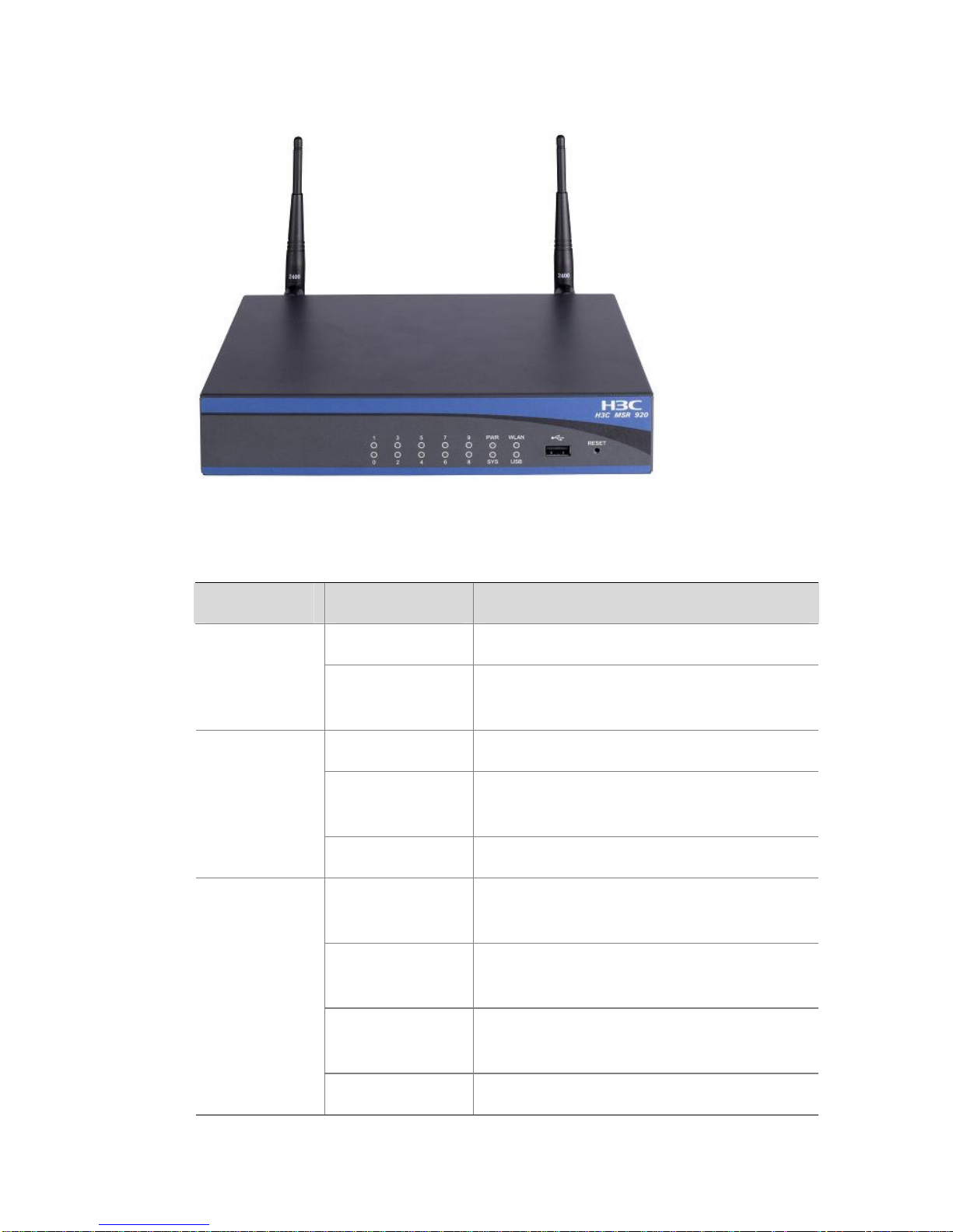
1-3
Figure 1-2 Front panel of the MSR 920/MSR 920W
Table 1-2 Description of the LEDs, USB interface, and RESET button
Item Status Description
Off No power supply is present.
Power
supply LED
(PWR)
On
The power supply operates
normally.
Slow blinking The system operates normally.
Fast blinking
The system is working in situations
with large traffic flow.
WLAN LED
(WLAN)
Off The system operates abnormally.
Fast blinking
(green)
The system is starting up.
Slow blinking
(green)
The system operates normally.
Fast blinking
(yellow)
The system is faulty.
System
LED (SYS)
Off The system operates abnormally.
Page 12

1-4
Item Status Description
On A link is present.
Blinking
Data is being transmitted or
received.
Ethernet
interface
LEDs (0 to
9)
Off No link is present.
USB
interface
— Connecting to a USB device
RESET
button
—
Pressing the RESET button for over
three seconds to restore the factory
default settings
Generally, the WLAN LED on a wired MSR device (MSR 900 and
MSR 920) stays off.
Rear Panel
Figure 1-3 Rear panel of the MSR 900/MSR 900W
Page 13

1-5
Figure 1-4 Rear panel of the MSR 920/MSR 920W
Table 1-3 Description of the interfaces and antennas
Item Description
Console port
(CONSOLE)
Connecting to a PC through a console
cable for system configuration
Fixed Ethernet
interfaces (ETH 0 and
ETH 1)
Uplink Layer 3 Ethernet interfaces for
WAN connections
Fixed Ethernet
interfaces (ETH 2 to
ETH 9)
Downlink Layer 2 Ethernet interfaces for
connections to user terminals or swit ches
Antenna Transmitting radio frequency signals
DC power input Connecting to the supplied power adapter
z Only the MSR 900W and MSR 920W require antenna installation.
z The MSR 900W requires one antenna while the MSR 920W
requires two antennas.
Page 14
2-1
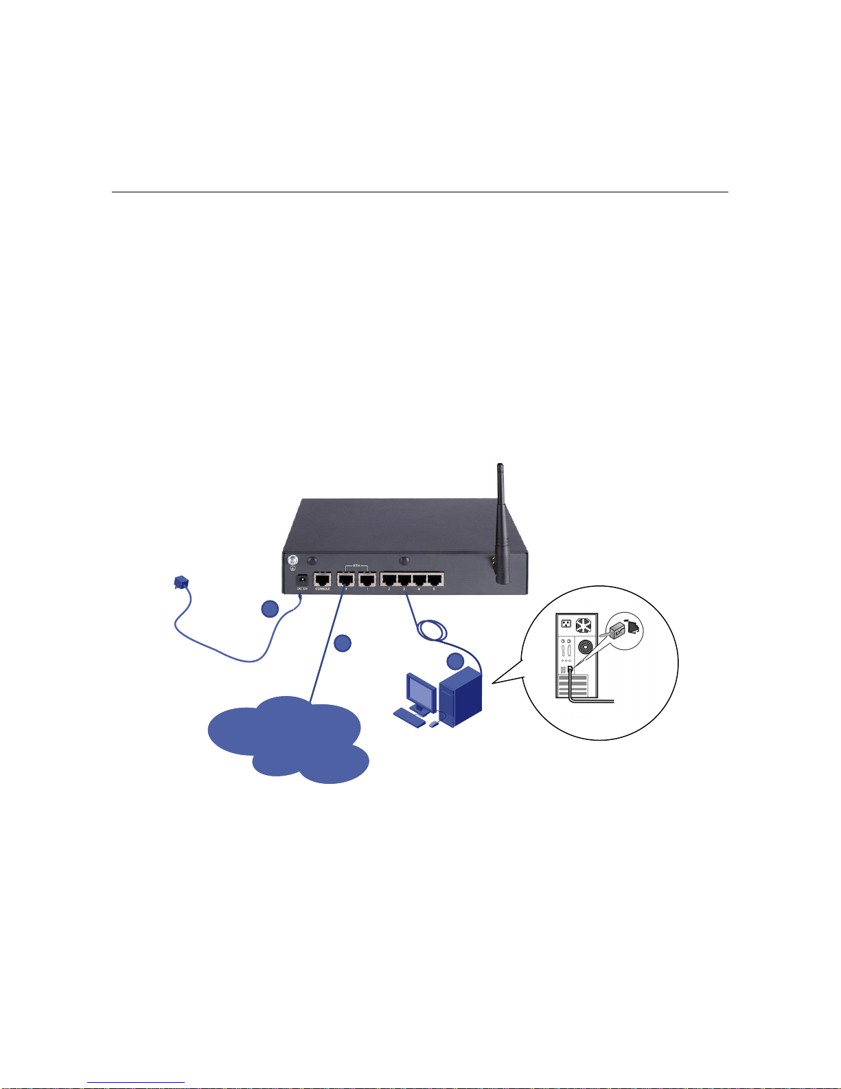
2 Cable Connection
Follow these steps to connect cables for the MSR 900:
Step1 Use a network cable to connect the uplink Ethernet interface (ETH 0
or ETH 1) to a WLAN access point.
Step2 Use network cables to connect the do wnlink Ethernet interfaces to the
Ethernet interfaces on user terminals.
Step3 Connect the power adapter to the power input.
Figure 2-1 Cable connection
192.168.1.1/24
WAN
1
2
3
User host
Page 15

3-1
3 Service Configuration
This configuration example uses a user terminal runni ng Windows XP
and Internet Explorer 6.0.
Logging In to the Web Interface
Follow these steps to log in to the Web interface for the first time:
Step1 T ype the default IP address http://192.168.1.1 in the address bar and
press Enter to enter the page shown in
Figure 3-1.
Figure 3-1 Web login interface
Step2 Type the username, password (admin/admin by default) and verify
code and then click Login. After a successful verification, you can
enter the web configuration page sho wn in
Figure 3-2.
Page 16

3-2
Figure 3-2 Web configuration page
Network Access
Configuring Internet Access Through the Wizard
The wizard allows you to set the parameters for Internet access
quickly as following the system prompts.
Step1 Select Wizard > Basic Configuration Wizard from the navigation
tree in the configuration page to enter the welcome page shown in
Figure 3-3.
Figure 3-3 Basic configuration wizard
Page 17

3-3
Step2 Click Next>> to enter the page displaying LAN interface parameters,
as shown in
Figure 3-4.
Figure 3-4 LAN interface configuration page
z By default, all Ethernet interfaces belong to VLAN 1. Therefore,
you need to specify the IP address and mask of the device as the
IP address and subnet mask of VLAN 1.
z You can also configure the device to act as a DHCP server to
dynamically assign IP addresses for the terminals. To do this,
select the radio button before Enable in the page shown above
and type the address range of the DHCP address pool in the
Start IP Address and End IP Address fields.
The IP address of the device cannot be included in the DHCP
address pool.
Page 18

3-4
z Type the IP address of the device in the Gateway IP Address
field to specify the device as a gateway. The gateway is
responsible for data forwarding when DHCP clients access
servers or hosts outside the current network segment. With the
gateway address specified for the address pool, the device acts
as the DHCP server and sends the gateway address together
with the IP addresses to the clients.
z To enable DHCP clients to access a host on the Internet via the
domain name, the DHCP server also sends IP addresses of two
DNS servers to the clients, with DNS server 1 in preference of
DNS server 2.
Step3 After configuring the parameters for the LAN interfaces, click Next>>
to enter the page for configuring the parameters for the WAN
interfaces, as shown in
Figure 3-5.
Figure 3-5 WAN interface configuration page
z Set the WAN interface to Ethernet0/0 so that Ethernet 0/0
serves as the uplink interface for network access. Set the
Connect Mode to PPPoE.
z Enter the username and password for network access.
Page 19

3-5
Step4 Click Next>> after the configurations to enter the p age displ aying the
configuration information, as shown in
Figure 3-6.
Figure 3-6 Basic configuration confirmation page
Step5 Click Finish if the configuration information is correct. The system
thus saves the configurations automatically. Click Close on the page
shown below to finish the operation.
Figure 3-7 Current configuration displaying page
Configuring Broadband Internet Access Manually
Follow these steps to configure Internet access manually:
Page 20

3-6
Step1 Select Interface Setup > LAN Interface Setup from the navigation
tree and select the VLAN Interface Setup tab to enter the page
shown in
Figure 3-8.
Figure 3-8 VLAN interface configuration page
z By default, all Ethernet interfaces belong to VLAN 1. Therefore,
you need to specify the IP address and mask of the device as the
IP address and subnet mask of VLAN 1.
z You can also configure the device to act as a DHCP server to
dynamically assign IP addresses for the terminals. To do this,
select the radio button before Enable in the p age above and type
the address range of the DHCP address pool in the Start IP
Address and End IP Address fields.
The IP address of the device cannot be included in the DHCP
address pool.
Page 21

3-7
z Type the IP address of the device in the Gateway field to specify
the device as a gateway. The gateway is responsible for data
forwarding when DHCP clients access servers or hosts outside
the current network segment. With the gateway address
specified for the address pool, the device acts as the DHCP
server and sends the gateway address together with the IP
addresses to the clients.
z To enable DHCP clients to access a host on the Internet via the
domain name, the DHCP server also sends IP addresses of two
DNS servers to the clients, with DNS server 1 in preference of
DNS server 2.
Step2 Select Interface Setup > WAN Interface Setup from the navigation
tree and click the operation icon corresponding to Ethernet 0/0, as
shown in
Figure 3-9.
Figure 3-9 WAN interface configuration page
Step3 Set the Connect Mode to PPPoE to enter the page shown in
Figure
3-10.
Page 22

3-8
Figure 3-10 Configure PPPoE parameters
Step4 Type the username and password for network access and click
Confirm.
Creating WLAN Connections
Follow these steps to establish a wireless connection if a host is
willing to access the network through WLAN and it supports 802.1b/g:
Step1 Select Interface Setup > Wireless > Access Service from the
navigation tree. Then click New to enter the page for creating a
wireless connection as shown in
Figure 3-11.
Figure 3-11 Create a wireless connection
Page 23

3-9
Step2 Type the wireless service name, set the service type to crypto, and
click Apply to bring the configuration into effect
Figure 3-12 Wireless connection configuration page
Step3 Configure a password for accessing the created WLAN (SSID). After
creating a WLAN service, you can enter the page shown in
Figure
3-13.
Figure 3-13 Access service security configuration page
Page 24

3-10
Step4 Click the plus sign “+” before Security Setup, set Authentication
Type to OpenSystem, select the checkbox before Encryption, set
WEP to WEP40, specify Key ID and Key Length, and enter the key
in the WEP Key field.
You can configure multiple SSIDs and assign different key IDs for
them in case WEP encryption mode is selected. Click Apply to
complete the configuration.
Step5 Configure the WLAN client in the operating system of the user
terminal. Take Windows XP for example. Click Start > All Programs
> Control Panel.
Figure 3-14 Enter the control panel page
Step6 Click Network and Internet Connections under Pick a category to
enter the page shown in
Figure 3-16.
Page 25

3-11
Figure 3-15 Enter network and Internet connection page
Figure 3-16 Network connection displaying page
Step7 Double-click the Wireless icon to enter the WLAN connection
configuration page. Then click Refresh net work list in the navigation
bar to search for available WLAN networks. A page displaying the
current WLAN networks may appear as shown in
Figure 3-17.
Page 26

3-12
Figure 3-17 WLAN connection configuration page
Step8 Click Change advanced settings in the left navigation bar to enter
the page shown below.
Page 27

3-13
Figure 3-18 Enter advanced configuration page
Step9 Click the Wireless Networks tab to enter the page shown in
Figure
3-19, select the self-defined SSID displayed in the Preferred
networks field, and then click Properties.
Page 28

3-14
Figure 3-19 WLAN connection configuration page
Step10 Specify the Key index value as the key ID configured on the devi ce
and click OK.
Page 29

3-15
Figure 3-20 Configure the key index
Step11 After returning to the page shown in
Figure 3-18, select the WLAN
connection configured on the router and click Connect to enter the
page shown in
Figure 3-21. Then type the key and click Connect.
Page 30

3-16
Figure 3-21 Enter the key for WLAN a ccess
Step12 Appearance of the page shown in
Figure 3-22 indicates a
successful WLAN connecti on, that is, you can access the Internet via
the WLAN connection.
Figure 3-22 Successful WLAN connection
Access Control
The access control function allows you to control the user access to
the Internet. For example, you can prevent users from accessing
stock-related websites from 9:00 to 17:00, Monday through Friday.
Page 31

3-17
You can configure access control rules to define the time period, user
IP addresses, port range, and data packet types. The MSR 900
supports configuring up to five access control rules, in the order the
rules are configured.
Select Securi ty Setup > Access from the navigation tree to enter the
page shown in
Figure 3-23.
Figure 3-23 Access control configuration page
Table 3-1 Description of the configuration items
Item Description
Begin-End
Time
Specifies the time period in which the rule is active,
with the end time ahead of the start time.
Week
Specifies the days in a week on which the rule is
active.
Protocol
Specifies the protocol used for transmitting packets.
This function allows access control by protocol,
which can be TCP, UDP and IP. “IP” refers to all
protocols.
Source IP
Address
Specifies the IP address range of hosts on the LAN
to be controlled.
To control the access of a single IP address,
192.168.1.2 for example, enter 192.168.1.2 ~
192.168.1.2.
Page 32

3-18
Item Description
Destination
Port
Specifies the ports through which hosts on the LAN
access the Internet.
For example, for the telnet port (23), enter 23 ~ 23.
Operation
Specifies the status of the rule:
z Deny: Filters out packets matching the rule while
allowing other packets to pass.
z Permit: Filters out all packets except those
matching the rule.
z None: The rule is ineffective.
Table 3-2 Common services and corresponding port numbers
Service Protocol Port number
FTP service TCP 21
Telnet service TCP 23
TFTP service UDP 69
Web service TCP 80
Content Filtering
The content filtering function allows you to control the websites users
can access. You can perform such content filtering by the host names,
protocol types, or website addresses.
Follow these steps to configure content filtering rules:
Select Security Setup > URL Filter fro m the navigation tree to enter
the URL filtering configu ration page shown below.
Page 33

3-19
Figure 3-24 URL filtering configuration page
In this configuration page, you can configure the filtering rules as
needed and click Filter to finish the configuration process. Then the
filtering rules are displayed in the Select the filtering condition
value(s) field and these rules take effect instantly.
Table 3-3 describes the URL filtering con f iguration items.
Table 3-3 Description of the URL filtering configuration items
Item Description
URL
Specifies the URL
address, which can be
a regular expression
Keyword
Specifies the keyword
to be filtered, which can
be a regular expression
For the effect of the
configuration with
both the URL
address and
keyword specified,
see
Table 3-4.
Import
filter list
file
File
Name
Specifies that the filtering conditions are
imported from the URL filtering list file on the
host and specifies the path and file name of the
file.
Page 34

3-20
Table 3-4 Description of the configuration effect
URL address Keyword Description
www.abc.com —
Filters out all pages of the
specified website
www.abc.com /index.html
Filters out the /index.html
page of the specified website
www.abc.com /index.html?
Filters out the /index.html and
/index.htm pages of the
specified website
(news|tech)\.ab
c\.com
—
Filters out all pages of the
specified sub-websites, such
as news.abc.com and
tech.abc.com
(news|tech)\.ab
c\.com
/index.html
Filters out the /index.html
pages of the specified
sub-websites
(news|tech)\.ab
c\.com
/index.html?
Filters out the /index.html and
/index.htm pages of the
specified sub-websites
To remove a filtering rule, select the rule from the Select the filtering
condition value(s) field and click Delete.
Modifying User Password
You can modify the password for logging in to the configuration p age.
The initial username and password are both admin. Follow these
steps to modify the password:
Select System Management > Users from the navigation tree and
click the Modify User tab to enter the user management
configuration page.
Page 35

3-21
Figure 3-25 User management configuration page
Select the username from the user list, select the checkbox before
Password Modify, type the new password and confirm it, and click
Apply to finish the operation.
Page 36

4-1
4 System Management
Saving the Configuration
Select System Management > Configuration from the navigation
tree to enter the Save tab page, which is displayed by default, as
shown in
Figure 4-1.
Figure 4-1 Save the configuration
Click Sav e Current Settings to save the current configurations to the
configuration file.
z It takes some time for the system to save the configurations.
z The system does not support two or more users to save
configuration simultaneously. If such a case occurs, the system
will prompt the latter users to try again later.
Initialization
Select System Management > Configuration from the navigation
tree and click the Initialize tab to enter the page sho wn in
Figure 4-2.
Page 37

4-2
Figure 4-2 Initialization
Click Restore Factory-Default Settings to restore the initial settings.
Configuration File Backup
The configuration file backup module delivers the follo wing function s:
z View the configuration file for the next boot, including .cfg
and .xml files.
z Back up the configuration file for the next boot to the local user
host.
Select System Management > Configuration from the navigation
tree and click the Backup tab to enter the page sh own in
Figure 4-3.
Figure 4-3 Backup the configuration file
z Click Backup and you will see a dialog box, where you can open
the configuration file for the next boot or save it to the local
device.
z Click Backup and you will see a dialog box, where you can open
the configuration file for the next boot or save it to the local
device.
Page 38

4-3
Configuration Restoration
The configuration restoration function allows you to upload the
configuration file with the extension of .cfg to the device in use for the
next system boot.
Select System Management > Configuration from the navigation
tree and click the Restore tab to enter the page shown in
Figure 4-4.
Figure 4-4 Restore the configuration file
z Click Browse… and specify the configuration file with the
extension of .cfg to be uploaded from the pop-up dialog box.
Then click OK to start uploading the configuration file.
z Click Browse… and specify the configuration file with the
extension of .xml to be uploaded from the pop-up dialog box.
Then click OK to start uploading the configuration file.
Backup & Restoration Through USB Interface
The files needed in device running, such as application files and
configuration files, are stored in the storage medium of the device. To
facilitate management of the files on the device, the device provides
the fast backup and restoration functions.
z Fast backup: Backs up files on the device to the destination
device through the USB interface.
z Fast restoration: Uploads files to the local device through a USB
interface. You can specify the uploaded application file or
configuration file as the main application or configuration file.
Page 39

4-4
Select System Management > Configuration from the navigation
tree and click the Backup and Restore tab to enter the page shown
in
Figure 4-5.
Figure 4-5 Quick backup and restoration through the USB interface
z In the Device File(s) area, select the files to be backed up, and
click the Backup button to backup the selected files to the
destination device through the USB interface.
z In the USB File(s) area, select the files to be restored, and click
the Restore button to transfer the selected files to the device
through the USB interface.
Page 40

4-5
z At a time, you can restore multiple files, but only one application
file or configuration file can be included for restoration.
z Use the USB devices provided by H3C only for backing up and
restoring configuration files.
Reboot
Before rebooting the device, save the configurations; otherwise, any
configuration changes that have not been saved will get lost after the
system reboots. After the device reboots, you need to re-log in to the
Web interface.
Select System Management > Reboot from the navigation tree to
enter the page shown in
Figure 4-6. Click Apply to reboot the device.
Figure 4-6 Reboot the device
Page 41

4-6
You can choose to check whether the current configuration has been
saved to the configuration file to be used at the next startup.
z If you select the checkbox before “Check whether the current
configuration is saved in the next startup configuration file”,
the system will check the configuration before rebooting the
device. If the check succeeds, the system reboots the device; if
the check fails, the system pops up a prompt to inform that the
current configuration file and the saved configuration file are
inconsistent. As a result, the system will not reboot the device. In
this case, you need to save the current configuration manually
before you can reboot the device.
z If you do not select the checkbox, the system reboots the device
directly.
SNMP
Simple Network Management Protocol (SNMP) offers the
communication rules between a management device and the
managed devices on the network. SNMP enables network
administrators to search and modify information, locate and diagnose
network problems, plan for network growth, and generate reports on
network nodes.
Currently, there are three SNMP versions, SNMP v1, SNMP v2, and
SNMP v3.
Configuring SNMP v1 and SNMP v2
Select System Management > SNMP from the navigation tree to
enter the page shown in
Figure 4-7.
Page 42

4-7
Figure 4-7 SNMP v1 and SNMP v2 configuration page
z Select the radio button before Enable to enable SNMP.
z Select the radio button before SNMPv1&v2 to specify the SNMP
version.
z Configure Read Pass word and Read & Write Password , which
are used when the NMS performs read or read-write operations
on the device. Configure Trap Password, which is used for
authenticating the trap messages sent from the device to the
NMS.
z You can specify the IP address of the NMS trusted by the agent
in the Trusted Host field as needed. Thus only the specified
NMS can access the device. Any NMS can access the device if
this field is not specified.
z Specify the IP address of the host to which the SNMP trap
messages are sent in the Trap Target Host field.
z Click Apply to finish the configuration.
Page 43

4-8
Configuring SNMP v3
Select System Management > SNMP from the navigation tree to
enter the page shown in
Figure 4-8.
Figure 4-8 SNMP v3 configuration page
z Select the radio button before Enable to enable SNMP.
z Select the radio button before SNMPv3 to specify the SNMP
version.
z Enter the information of the manufacturer in the Contact
Information field to ensure that the information is available when
needed.
z Configure the system name in the Sysname field. The system
name will be displayed in the upper left of the navigation bar.
z Enter the location of the device in the Device Location field so
as to facilitate location of faulty devices during troubleshooting.
Page 44

4-9
z Configure the security username, authentication password, and
encryption password in the Security Username,
Authentication Password, and Privacy Password fields
respectively. SNMP v3 supports MD5 authentication and DES56
encryption.
Page 45

5-1
5 Troubleshooting
The power LED (PWR) is off
Observe the following points:
z A proper power adapter is used.
z The power cord is correctly connected.
z The power switch is turned on.
The Ethernet interface LED (ETH) is off
Observe the following points:
z The network cable is correctly connected.
z The network cable is firmly connected.
The LAN LED (LAN) is off
Observe the following points:
z A proper network cable is used to connect the device and the
computer.
z The network cable is correctly connected.
z The LED for the network card of the computer is on.
z The network card of the computer operates normally.
You can open the Device Manager in the Windows operating system
and check whether a question mark “?” or an exclamation mark “!”
exists on items under Network adaptors. If such a mark exists, you
can try to uninstall the device and inst all it again or inst all the network
card in another slot. If the problem remains, install a new network
card.
Page 46

5-2
Restores to the factory default settings
You can press the RESET button on the front panel and hold it for
over three seconds to restore the system to the factory default
settings.
Fails to connect to the Internet though the AP can be found
Check that the SSID of the wireless NIC of the computer and the key
are correctly configured.
Suffers weak or unstable radio signals
Observe the following points:
z Strong magnetic fields nearby or radio wave interference can be
a problem. Keep the MSR 900 series routers and the user
terminals away from strong magnetic fields and elect rical devices
with strong electric fields.
z Materials such as cement and boards may partially or totally
block radio signals. It is recommended to install the MSR 900 in
open spaces.
z The user terminal is far away from the MSR 900. Move the user
terminal closer and try again.
z Lightning strikes may also cause interference in WLAN
connections.
 Loading...