

H3C MSR830 Series, MSR830-6EI-GL, MSR830-10EI-GL, MSR830-6HI-GL, MSR830-10HI-GL Installation Manual
Page 1

New H3C Technologies Co., Ltd.
http://www.h3c.com
Document version: 6W100-20180818
H3C MSR830 Router Series
Installation Guide
Page 2

Copyright © 2018, New H3C Technologies Co., Ltd. and its licensors
All rights reserved
No part of this manual may be reproduced or transmitted in any form or by any means without prior written
consent of New H3C Technologies Co., Ltd.
Trademarks
H3C, , H3CS, H3CIE, H3CNE, Aoly nk, , H
3
Care, , IRF, NetPilot, Netflow, SecEngine,
SecPath, SecCenter, SecBlade, Comware, ITCMM and HUASAN are trademarks of New H3C Technologies
Co., Ltd.
All other trademarks that may be mentioned in this manual are the property of their respective owners.
Notice
The information in this document is subject to change without notice. All contents in this document, including
statements, information, and recommendations, are believed to be accurate, but they are presented without
warranty of any kind, express or implied. H3C shall not be liable for technical or editorial errors or omissions
contained herein.
Environmental protection
This product has been designed to comply with the environmental protection requirements. The storage, use,
and disposal of this product must meet the applicable national laws and regulations.
Page 3

Preface
The H3C MSR830 Router Series Installation Guide includes seven chapters, which describe the
preparing for installation, installing the router, replacement procedure, troubleshooting, chassis
views and technical specifications, LEDs, and slot arrangement.
This preface includes the following topics about the documentation:
• Audience.
• Conventions.
• Documentation feedback.
Audience
This documentation is intended for:
• Network planners.
• Field technical support and servicing engineers.
• Network administrators working with the MSR830 Router Series.
Conventions
The following information describes the conventions used in the documentation.
Command conventions
Convention Description
Boldface Bold
Italic
[ ] Square brackets enclose syntax choices (keywords or arguments) that are optional.
{ x | y | ... }
[ x | y | ... ]
{ x | y | ... } *
[ x | y | ... ] *
&<1-n>
# A line that starts with a pound (#) sign is comments.
GUI conventions
Convention Description
Boldface
text represents commands and keywords that you enter literally as shown.
Italic text represents arguments that you replace with actual values.
Braces enclose a set of required syntax choices separated by vertical bars, from which
you select one.
Square brackets enclose a set of optional syntax choices separated by vertical bars,
from which you select one or none.
Asterisk marked braces enclose a set of required syntax choices separated by vertical
bars, from which you select a minimum of one.
Asterisk marked square brackets enclose optional syntax choices separated by vertical
bars, from which you select one choice, multiple choices, or none.
The argument or keyword and argument combination before the ampersand (&) sign
can be entered 1 to n times.
Window names, button names, field names, and menu items are in Boldface. For
example, the
New User
window opens; click OK.
Page 4
Symbols
Convention Description
>
Multi-level menus are separated by angle brackets. For example,
Folder
.
Convention Description
WARNING!
An alert that calls attention to important information that if not understood or followed
can result in personal injury.
File
>
Create
>
CAUTION:
IMPORTANT:
NOTE:
TIP:
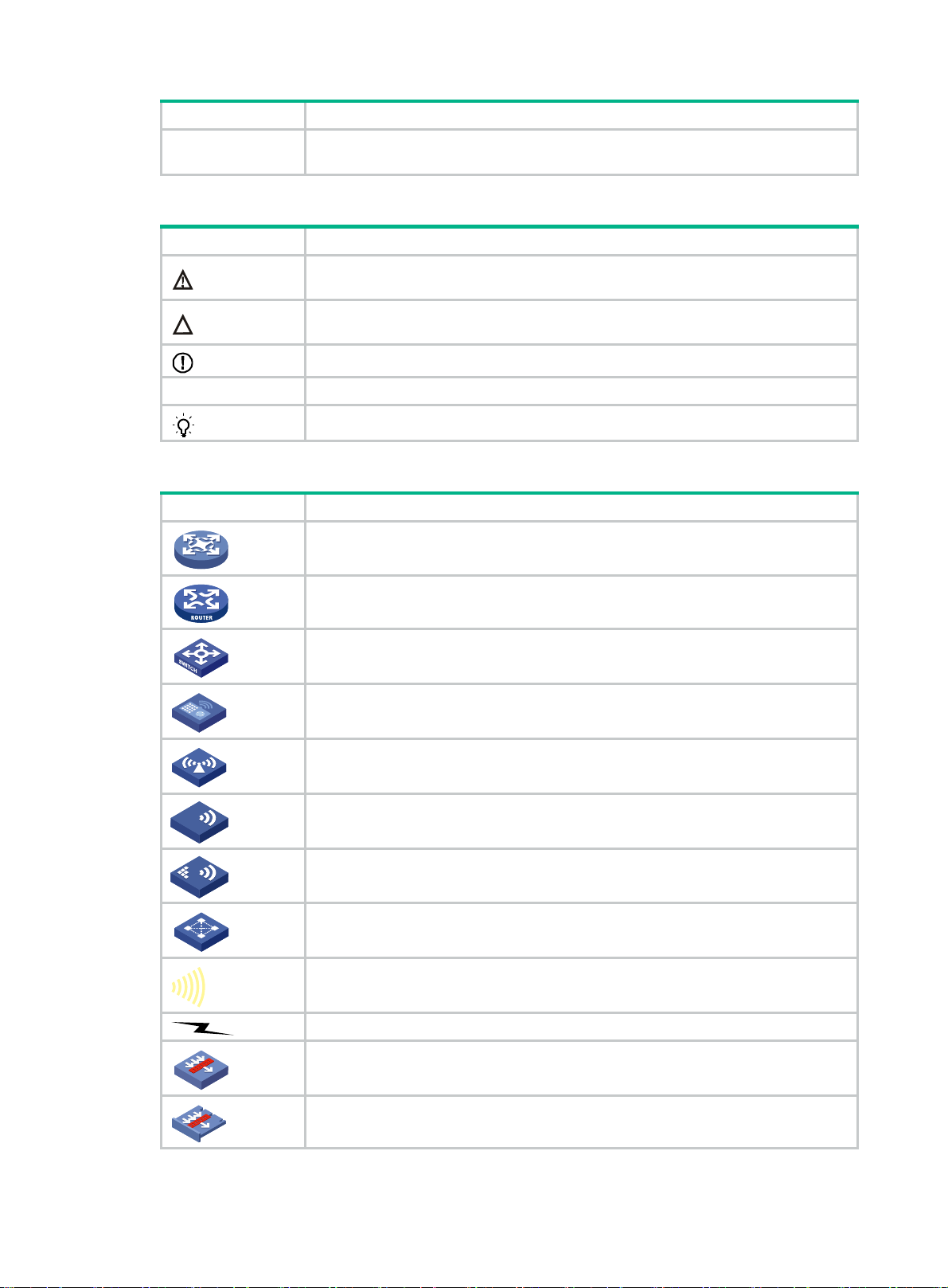
Network topology icons
Convention Description
An alert that calls attention to important information that if not understood or followed
can result in data loss, data corruption, or damage to hardware or software.
An alert that calls attention to essential information.
An alert that contains additional or supplementary information.
An alert that provides helpful information.
Represents a generic network device, such as a router, switch, or firewall.
Represents a routing-capable device, such as a router or Layer 3 switch.
Represents a generic switch, such as a Layer 2 or Layer 3 switch, or a router that
supports Layer 2 forwarding and other Layer 2 features.
Represents an access controller, a unified wired-WLAN module, or the access
controller engine on a unified wired-WLAN switch.
Represents an access point.
T
T
T
T
Represents a wireless terminator unit.
Represents a wireless terminator.
Represents a mesh access point.
Represents omnidirectional signals.
Represents directional signals.
Represents a security product, such as a firewall, UTM, multiservice security
gateway, or load balancing device.
Represents a security module, such as a firewall, load balancing, NetStream, SSL
VPN, IPS, or ACG module.
Page 5

Examples provided in this document
Examples in this document might use devices that differ from your device in hardware model,
configuration, or software version. It is normal that the port numbers, sample output, screenshots,
and other information in the examples differ from what you have on your device.
Documentation feedback
You can e-mail your comments about product documentation to info@h3c.com.
We appreciate your comments.
Page 6

Contents
Preparing for installation ···································································· 1
Safety recommendations ············································································································· 1
Safety symbols ··················································································································· 1
General safety recommendations ··························································································· 1
Electricity safety ·················································································································· 1
Examining the installation site ······································································································· 1
Temperature and humidity ····································································································· 2
Cleanliness ························································································································ 2
Cooling system ··················································································································· 2
ESD prevention ··················································································································· 3
EMI ·································································································································· 3
Lightning protection ············································································································· 3
Rack-mounting ··················································································································· 4
Installation tools ························································································································· 4
Installation accessories ··············································································································· 4
Pre-installation checklist ·············································································································· 5
Installing the router ··········································································· 6
Installation prerequisites ·············································································································· 6
Installation flow ·························································································································· 6
Installing the router ····················································································································· 8
Mounting the router on a workbench ························································································ 8
Installing the router in a rack ·································································································· 8
Grounding the router················································································································· 10
Attaching the ring terminal to the grounding cable ···································································· 10
Grounding the router with a grounding strip ············································································· 11
Grounding the router through the rack···················································································· 11
Installing a Micro SD card ·········································································································· 12
Connecting a USB drive ············································································································ 13
Connecting interface cables ······································································································· 13
Connecting an AC power cord ······························································································ 13
Connecting an Ethernet cable ······························································································ 14
Connecting an optical fiber ·································································································· 15
Connecting the console cable and setting terminal parameters ·························································· 16
Connecting the console cable ······························································································ 16
Setting terminal parameters ································································································· 16
Verifying the installation ············································································································· 17
Accessing the router for the first time ··························································································· 17
Replacement procedure ·································································· 19
Replacing a Micro SD card ········································································································· 19
Replacing a transceiver module ·································································································· 20
Troubleshooting ············································································· 21
Power supply system failure ······································································································· 21
Configuration terminal issues ······································································································ 21
No terminal display ············································································································ 21
Garbled terminal display ····································································································· 22
No response from the serial port ··························································································· 22
Restoring the factory settings ····································································································· 22
Scenario 1 ······················································································································· 22
Scenario 2 ······················································································································· 22
Scenario 3 ······················································································································· 23
Reset button usage guidelines ····························································································· 23
Appendix A Chassis views and technical specifications ·························· 24
Chassis views ························································································································· 24
i
Page 7

MSR830-6EI-GL ··············································································································· 24
MSR830-6HI-GL ··············································································································· 24
MSR830-10HI-GL ·············································································································· 25
MSR830-10EI-GL ·············································································································· 25
Technical specifications ············································································································· 26
Appendix B LEDs ··········································································· 27
Panel LEDs ···························································································································· 27
MSR830-6EI-GL ··············································································································· 27
MSR830-6HI-GL ··············································································································· 27
MSR830-10HI-GL ·············································································································· 28
MSR830-10EI-GL ·············································································································· 28
LED description ······················································································································· 28
Index ··························································································· 30
ii
Page 8
Preparing for installation
Figure 1 This document applies to the following device models:
Model Product code
MSR830-6EI-GL RT-MSR830-6EI-GL
MSR830-6HI-GL RT-MSR830-6HI-GL
MSR830-10HI-GL RT-MSR830-10HI-GL
MSR830-10EI-GL RT-MSR830-10EI-GL
Safety recommendations
Safety symbols
When reading this document, note the following symbols:
WARNING means an alert that calls attention to important information that if not understood or
followed can result in personal injury.
CAUTION means an alert that calls attention to important information that if not understood or
followed can result in data loss, data corruption, or damage to hardware or software.
General safety recommendations
• Keep the chassis and installation tools away from walk areas.
• Make sure the ground is dry and flat and anti-slip measures are in place.
• Unplug all the external cables (including power cords) before moving the chassis.
Electricity safety
• Locate the emergency power-off switch in the room before installation. Shut the power off at
once in case accident occurs. Disconnect the power cord of the router if necessary.
• Make sure the router is correctly grounded.
• Do not open or close the chassis cover when the router is powered on.
• Correctly connect the interface cables of the router.
• Use an uninterrupted power supply (UPS).
• Do not work alone when the router has power.
• Always make sure the power has been disconnected during the installation and replacement
procedures.
Examining the installation site
The router can only be used indoors. To make sure the router operates correctly and to prolong its
service lifetime, the installation site must meet the following requirements.
1
Page 9

Temperature and humidity
Maintain temperature and humidity in the equipment room at acceptable levels.
• Lasting high relative humidity tends to cause poor insulation, electricity leakage, mechanical
property change of materials, and corrosion of metal parts.
• Lasting low relative humidity is likely to result in loose screws due to washer contraction, and
even ESD, which causes the circuits to fail.
• A high temperature is the most undesirable condition, because it accelerates the aging of
insulation materials and significantly lowers reliability and service life of the router.
For the temperature and humidity requirements of the router, see Table 1.
Table 1
Temperature and humidity requirements
Temperature Humidity
0°C to 45°C (32°F to 113°F) 5% to 90% (noncondensing)
Cleanliness
Dust buildup on the chassis might result in electrostatic adsorption, which causes poor contact of
metal components and contact points, especially when indoor relative humidity is low. In the worst
case, electrostatic adsorption can cause communication failure.
Table 2 Dust concentration limit in the equipment room
Substance Concentration limit (particles/m
Dust particles
NOTE:
Dust particle diameter ≥ 5 µm
The equipment room must also meet limits on salts, acids, and sulfides to eliminate corrosion and
premature aging of components, as shown in Table 3.
Table 3
Harmful gas limits in the equipment room
≤ 3 x 10⁴
(No visible dust on desk in three days)
3
)
Gas Max. (mg/m
SO2 0.2
H2S 0.006
NH
3
Cl
2
NO2 0.04
Cl2 0.01
Cooling system
To ensure good ventilation, the following requirements must be met:
• The air inlet and outlet vents are not blocked, and leave at least 100 mm (3.94 in) of clearance.
• The installation site has a good cooling system.
0.05
0.01
3
)
2
Page 10

ESD prevention
CAUTION:
Check the resistance of the ESD wrist strap for safety. The resistance reading must be in the range
of 1 to 10 megohm (Mohm) between human body and the ground.
To prevent electrostatic discharge (ESD), follow these guidelines:
• Make sure the router and the floor are correctly grounded.
• Take dust-proof measures for the equipment room.
• Maintain the humidity and temperature at acceptable levels.
• Always wear an ESD wrist strap and ESD clothing when touching a circuit board or transceiver
module.
The router does not supply an ESD wrist strap. Prepare an ESD wrist strap yourself.
To attach an ESD wrist strap:
1. Wear the wrist strap on your wrist.
2. Lock the wrist strap tight around your wrist to keep good contact with the skin.
3. Secure the wrist strap lock and the alligator clip lock together.
4. Attach the alligator clip to the rack grounding terminal.
5. Make sure the rack is correctly grounded.
EMI
Electromagnetic interference (EMI) might be coupled from the source to the router through the
following coupling mechanisms:
• Capacitive coupling
• Inductive coupling
• Radiative coupling
• Common impedance coupling
• Conductive coupling
To prevent EMI, take the following actions:
• Take measures against interference from the power grid.
• Do not use the router together with the grounding equipment or lightning-prevention equipment
of power equipment, and keep the router far away from them.
• Keep the router far away from high-power radio launchers, radars, and equipment with high
frequency or high current.
• Use electromagnetic shielding when necessary.
Lightning protection
To better protect the router from lightning, do as follows:
• Make sure the grounding cable of the chassis is correctly grounded.
• Make sure the grounding terminal of the AC power receptacle is correctly grounded.
• Install a lightning arrester at the input end of the power supply to enhance the lightning
protection capability of the power supply.
3
Page 11
Rack-mounting
Before mounting the router in a standard 19-inch rack, adhere to the following requirements:
• The rack is equipped with a good ventilation system.
• The rack is sturdy enough to support the router and its accessories.
• For heat dissipation and device maintenance, make sure the front and rear of the rack are at
least 0.8 m (2.62 ft) away from walls or other devices, and the headroom in the equipment room
is no less than 3 m (9.84 ft).
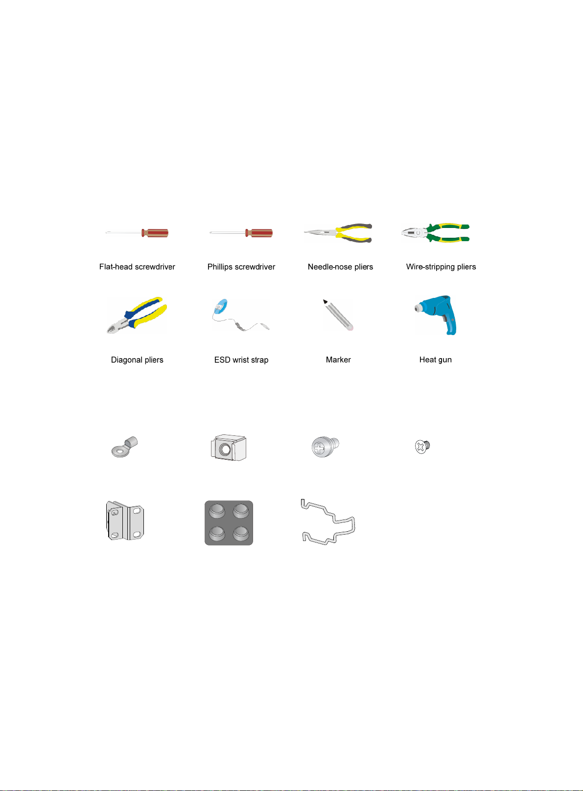
Installation tools
Installation accessories
Ring terminal
Mounting brackets
Cage nut (user-supplied) M6 rack screw
Rubber feet
Bail latch
M3 mounting bracket screw
4
Page 12

Pre-installation checklist
Table 4 Pre-installation checklist
Item Requirements Result
• There is a minimum clearance of 100 mm (3.94 in)
around the inlet and outlet vents for heat
Ventilation
dissipation of the router chassis.
• A good ventilation system is available at the
installation site.
Installation site
Safety
precautions
Tools
Reference
Temperature 0°C to 45°C (32°F to 113°F).
Humidity 5% RH to 90% RH (noncondensing).
Cleanliness
ESD prevention
EMI prevention
Lightning
protection
Electricity safety
Workbench
• The router is far away from any moist area and heat source.
• The emergency power switch in the equipment room is located.
• Installation accessories supplied with the router.
• User supplied tools.
• Documents shipped with the router.
• Online documents.
• Dust concentration ≤ 3 × 10⁴ particles/m3.
• No visible dust on desk within three days.
• The equipment and floor are correctly grounded.
• The equipment room is dust-proof.
• The humidity and temperature are at acceptable
levels, respectively.
• Wear an ESD wrist strap and uniform when
touching a circuit board.
• Take effective measures to protect the power
system from the power grid system.
• Separate the protection ground of the router from
the grounding device or lightning protection
grounding device as far as possible.
• Keep the router far away from radio stations, radar
and high-frequency devices working in high
current.
• Use electromagnetic shielding when necessary.
• The grounding cable of the chassis is correctly
grounded.
• The grounding terminal of the AC power
receptacle is correctly grounded.
• A port lightning arrester is installed. (Optional.)
• A power lightning arrester is installed. (Optional.)
• A signal lightning arrester is installed at the input
end of an external signal cable. (Optional.)
• Equip an UPS.
• The power-off switch in the equipment room is
identified and accessible so that the power can be
immediately shut off when an accident occurs.
• The workbench is stable enough.
• The workbench is correctly grounded.
5
Page 13

Installing the router
WARNING!
To avoid injury, do not touch bare wires, terminals, or parts with high-voltage hazard signs.
IMPORTANT:
• The barcode on the router chassis contains product information that must be provided to local
sales agent when you return a faulty router for service.
• Keep the tamper-proof seal on a mounting screw on the chassis cover intact, and if you want to
open the chassis, contact H3C for permission. Otherwise, H3C shall not be liable for any
consequence.
Installation prerequisites
• You have read "Preparing for installation" carefully.
• All requirements in "Preparing for installation" are me
t.
Installation flow
You can install the router on a workbench or in a rack. Select an installation method according to the
installation environment, and follow the installation flowchart shown in Figure 2.
6
Page 14

Figure 2 Installation flow
Start
Workbench-mounting
Mount the router on a
workbench
Determine the
installation position
Ground the router
Install a Micro SD card
Install a USB drive
Connect interface cables
Connect the router to a
configuration terminal
Rack-mounting
Mount the router in a rack
Connect the power cord
Verify the installation
Power on the router Troubleshoot the router
Power off the routerOperating correctly?
No
Yes
End
7
Page 15

Installing the router
Mounting the router on a workbench
IMPORTANT:
• Ensure good ventilation and 100 mm (3.94 in) of clearance around the chassis for heat
dissipation.
• Do not place heavy objects on the router.
To mount the router on a workbench:
1. Make sure the workbench is clean, stable, and correctly grounded.
2. Place the router upside down on the workbench and attach the rubber feet to the four round
holes in the chassis bottom.
Figure 3 Attaching the rubber feet
3. Place the router on the workbench with the upside up.
Figure 4 Mounting the router on a workbench
Installing the router in a rack
WARNING!
The mounting brackets can only support the weight of the router. To avoid damage to the router, do
not place any objects on the router.
8
Page 16

To install the router in a rack:
1. Use a mounting bracket to mark the positions of cage nuts on the front rack posts. Make sure
the cage nut installation holes on the front rack posts are on a horizontal line.
2. Install cage nuts, as shown in Figure 5.
a. Insert o
ne ear of a cage nut into the marked installation hole.
b. Use a flathead screwdriver to push the other ear into the same hole.
Figure 5 Installing cage nuts
3. Attach mounting brackets to both sides of the router, as shown in Figure 6.
Figure 6 Attaching the mounting bracket to the router
4. Use M6 screws to attach the mounting brackets on the router to the front rack posts, as shown
in Figure 7.
9
Page 17

Figure 7 Securing the router to the rack
Grounding the router
WARNING!
Correctly connecting the router grounding cable is crucial to lightning protection and EMI protection.
IMPORTANT:
The resistance reading must be smaller than 5 ohms between the chassis and the ground.
Attaching the ring terminal to the grounding cable
The router comes with a ring terminal. No grounding cable is provided with the router. Purchase a
grounding cable yourself. Before grounding the router, attach the provided ring terminal to the
grounding cable.
To attach the ring terminal to the grounding cable:
1. Cut the grounding cable to the desired length. Use the wire-stripping pliers to peel 5 mm (0.20 in)
of insulation sheath from one end of the grounding cable.
2. Add a heat-shrink tubing onto the cable, and insert the bare metal part of the grounding cable
into the ring terminal.
3. Use the needle-nose pliers to secure the metal part of the cable in the ring terminal.
4. Cover the joint with the heat-shrink tubing, and use a heat gun to shrink the tubing around the
cable.
10
Page 18

Figure 8 Attaching the ring terminal to the grounding cable
1
3
5
2
4
6
Grounding the router with a grounding strip
1. Remove the grounding screw from the grounding hole on the rear panel of the chassis.
2. Use the grounding screw to attach the ring terminal of the grounding cable to the grounding
hole.
3. Use a screwdriver to fasten the grounding screw.
4. Remove the hex nut from a grounding post on the grounding strip.
5. Use the removed hex nut to attach the other end of the grounding cable to the grounding post.
Figure 9 Connecting the router with a grounding strip
Grounding the router through the rack
IMPORTANT:
Make sure the rack is correctly grounded before grounding the router through the rack.
To connect the grounding cable through the rack:
1. Remove the grounding screw from the grounding hole on the rear panel of the chassis.
2. Use the grounding screw to attach the ring terminal of the grounding cable to the grounding
hole.
3. Use a screwdriver to fasten the grounding screw.
11
Page 19

4. Remove the nut from the grounding post of the grounding point on the rack.
5. Use the needle-nose pliers to bend a hook at the other end of the grounding cable, and use the
removed nut to attach the hook to the grounding post.
Figure 10 Grounding the router through the rack
Installing a Micro SD card
CAUTION:
To avoid damaging the Micro SD card slot, do not use excessive force when you install a Micro SD
card.
Only the MSR830-6HI-GL and MSR830-10HI-GL routers support Micro SD cards.
To install a Micro SD card:
1. Remove the screw on cover over the Micro SD card slot and remove the cover.
2. Insert the Micro SD card into the slot along the slide rails.
If you encounter any resistance, re-orient the card and try to insert it again.
3. Reinstall the cover and fasten the screw on the cover.
12
Page 20

Figure 11 Installing a Micro SD card
Connecting a USB drive
Connect a USB drive to the USB port of the router as shown in Figure 12.
Figure 12 Connecting a USB drive
Connecting interface cables
Connecting an AC power cord
1. Make sure the router is correctly grounded.
2. Attach the bail latch to the router.
3. Connect one end of the AC power cord to the AC receptacle on the router, and the other end to
the AC power source.
4. Use the bail latch to secure the power cord.
13
Page 21

Figure 13 Connecting an AC power cord
Connecting an Ethernet cable
1. Connect one end of the cable to an Ethernet port on the router and the other end to an Ethernet
port on the peer device.
2. Examine the port LED on the router. For more information about the LEDs, see "LED
description."
Figure 14 Connecting the Ethernet cable
14
Page 22

Connecting an optical fiber
WARNING!
Do not stare into any fiber port when you connect an optical fiber. The laser light emitted from the
optical fiber might hurt your eyes.
CAUTION:
• To connect a fiber port by using an optical fiber, first install a transceiver module in the port and
then connect the optical fiber to the transceiver module.
• Install a dust cap on any open optical fiber connector and insert a dust plug into any open fiber
port or transceiver module port to protect them from contamination and ESD damage.
• Never bend an optical fiber excessively. The bend radius of an optical fiber must be not less than
100 mm (3.94 in).
• Keep the fiber end clean.
• Make sure the Tx and Rx ports on a transceiver module are connected to the Rx and Tx ports on
the peer end, respectively.
Only the MSR830-6HI-GL and MSR830-10HI-GL routers support transceiver modules.
To connect an optical fiber:
1. Remove the dust plug from a fiber port of the router.
2. Remove the dust plug from the transceiver module, and plug the end without a pull latch into the
fiber port.
3. Remove the dust cap from the fiber connector.
4. Identify the Rx and Tx ports. Plug the LC connector at one end of one fiber cable into the Rx port
of the router and the LC connector at the other end into the Tx port of the peer device. Plug the
LC connector at one end of another fiber cable into the Tx port of the router and the LC
connector at the other end to the Rx port of the peer device.
5. Examine the fiber port LED. For more information, see "Appendix B LEDs."
Figure 15 Connecting an optical fiber
15
Page 23

Connecting the console cable and setting terminal parameters
To access the router at the first time, you can only use a console cable to connect the console port on
the router to a configuration terminal.
Connecting the console cable
IMPORTANT:
• When you connect a PC to a powered-on router, first connect the DB-9 connector of the console
cable to the PC, and then connect the RJ-45 connector to the router.
• If the PC does not have a DB-9 port, prepare a DB-9-to-RJ-45 adapter.
To connect the console cable:
1. Select a configuration terminal, which can be an ASCII terminal with an RS-232 serial port or a
PC. (A PC is more commonly used.)
2. Connect the DB-9 connector (female) of the console cable to the RS-232 serial port on the
configuration terminal and the RJ-45 connector to the console port of the router.
Figure 16 Connecting the console cable
Setting terminal parameters
To access the device through the console port, you must run a terminal emulator program
(HyperTerminal, PuTTY, or Tera Term) on the configuration terminal. For information about using a
terminal emulator program, see the program's user guide.
The following are the required terminal settings:
• Baud rate—9600.
• Data bits—8.
• Stop bits—1.
• Parity—none.
• Flow control—none.
16
Page 24

Verifying the installation
After you complete the installation, verify the following information:
• There is enough space for heat dissipation around the router, and the rack or workbench is
stable.
• The USB device, if any, is correctly installed.
• The router and the power source are correctly grounded.
• The correct power source is used.
• The router is connected correctly to the console terminal and other devices.
Accessing the router for the first time
WARNING!
Before powering on the router, locate the switch for the power source so that you can cut off power
promptly in case of an emergency.
For a router starting with empty configuration, you must press Ctrl+D to access the CLI.
To access the router for the first time:
1. Verify that the installation and configuration environment is as described in "Verifying the
installation."
2. Powe
3. During the booting process, verify the following items:
r on the router.
{ The system LED (SYS) on the front panel is flashing green at 1 Hz. For more information
about LEDs, see "Appendix B LEDs."
{ The configuration terminal displays information correctly.
The router first initializes its memory at startup and then runs BootWare.
System is starting...
Press Ctrl+D to access BASIC-BOOTWARE MENU
Booting Normal Extended BootWare
****************************************************************************
* *
* H3C MSR830 BootWare, Version 1.12 *
* *
****************************************************************************
Copyright (c) 2004-2017 New H3C Technologies Co., Ltd.
Compiled Date : Jun 20 2017
CPU ID : 0xc
CPU L1 Cache : 32KB
CPU L2 Cache : 1024KB
Memory Type : DDR3 SDRAM
Memory Size : 1024MB
Flash Size : 256MB
17
Page 25

PCB Version : 1.0
BootWare Validating...
Press Ctrl+B to access EXTENDED-BOOTWARE MENU...
Loading the main image files...
Loading file flash:/msr830hi-cmw710-system-e0707p02.bin.....................
.........................................Done.
Loading file flash:/msr830hi-cmw710-security-e0707p02.bin....Done.
Loading file flash:/msr830hi-cmw710-voice-e0707p02.bin....Done.
Loading file flash:/msr830hi-cmw710-data-e0707p02.bin......Done.
Loading file flash:/msr830hi-cmw710-boot-e0707p02.bin.........Done.
Image file flash:/msr830hi-cmw710-boot-e0707p02.bin is self-decompressing...
............................................................................
............................................................................
............................................................................
............................................................................
............................................................................
............................................................................
............................................................................
.................Done.
System image is starting...
Cryptographic algorithms tests passed.
Line con0 is available.
Press ENTER to get started.
4. Press Enter. The router is ready to configure when you see the following prompt:
<H3C>
5. Configure basic settings for the router. For more information, see the relevant documents.
18
Page 26

Replacement procedure
IMPORTANT:
• The barcode on the router chassis contains product information that must be provided to local
sales agent when you return a faulty router for service.
• Keep the tamper-proof seal on a mounting screw on the chassis cover intact, and if you want to
open the chassis, contact H3C for permission. Otherwise, H3C shall not be liable for any
consequence.
• Always wear an ESD wrist strap when you perform a replacement procedure.
Replacing a Micro SD card
CAUTION:
• The router supports hot swapping of Micro SD cards. Before hot-swapping a Micro SD card,
execute the umount command to avoid SD card damage and data loss.
• To avoid damaging the Micro SD card slot, do not use excessive force when you install a Micro
SD card.
To replace a Micro SD card:
1. Remove the screw on the cover over the Micro SD card slot and then remove the cover.
2. Push the Micro SD card horizontally to release it. The SD card will spring out from the slot.
3. Remove the Micro SD card from the slot.
Keep the removed Micro SD card for future use.
4. Install a new Micro SD card or install the slot cover if no new card is to be installed. For the
installation procedure, see "Installing a Micro SD card."
Figure 17 Removing a Micro SD card
1 2 3
19
Page 27

Replacing a transceiver module
1. Gently open the clasp on the transceiver module. If the clasp is obstructed and you cannot use
your finger to open it, use a pair of flat-head tweezers to open it.
2. Hold the clasp and pull the transceiver module slowly out of the fiber port.
3. Insert a dust plug into the transceiver module port and keep the removed transceiver module
secure.
4. Install a new transceiver module or insert a dust plug into the fiber port if you are not to install a
new transceiver module.
Figure 18 Removing a transceiver module
20
Page 28

Troubleshooting
IMPORTANT:
• The barcode on the router chassis contains product information that must be provided to local
sales agent when you return a faulty router for service.
• Keep the tamper-proof seal on a mounting screw on the chassis cover intact, and if you want to
open the chassis, contact H3C for permission. Otherwise, H3C shall not be liable for any
consequence.
Power supply system failure
Symptom
The router cannot be powered on. The system LED is off.
Solution
To resolve the issue:
1. Verify that the power cord of the router is correctly connected to the router and the power
source.
2. Verify that the power source is operating correctly.
3. Verify that the power cord is in good condition.
4. If the issue persists, contact H3C Support.
Configuration terminal issues
If the configuration environment setup is correct, the configuration terminal displays boot information
when the router is powered on. If the setup is incorrect, the configuration terminal displays nothing or
garbled text.
No terminal display
Symptom
The configuration terminal displays nothing when the router is powered on.
Solution
To resolve the issue:
1. Verify that the power supply system is operating correctly.
2. Verify that the console cable is correctly connected.
3. Verify that the console cable is connected to the serial port that is configured for the
configuration terminal.
4. Verify that the configuration terminal parameters are configured as follows:
{ Baud rate—9600
{ Data bits—8
{ Parity—none
{ Stop bits—1
{ Flow control—none
21
Page 29

{ Terminal emulation—VT100
5. Verify that the console cable is in good condition.
6. If the issue persists, contact H3C Support.
Garbled terminal display
Symptom
The configuration terminal displays garbled characters when the router is powered on.
Solution
Verify that the Data bits field is set to 8 for the configuration terminal. If the Data bits field is set to 5
or 6, the configuration terminal displays garbled characters.
No response from the serial port
Symptom
No boot information is displayed on the configuration terminal when the router starts up or restarts
up.
Solution
Verify that the serial cable is in good condition and the serial port settings are correct.
Restoring the factory settings
Scenario 1
Symptom
When you replace the router, the router password is lost. As a result, you cannot log in to the router
and do not know the router configuration.
Solution
Because the router is replaced, you do not need to save the configuration of the router. In this case,
you can press the RESET button for more than 4 seconds to reboot the router and restore the factory
settings. Then, you can use the username and password shipped with the router to log in to the
router.
When the router configuration must be saved and you have a console cable, you can log in to the
router through the BootWare menu.
Scenario 2
Symptom
Solution
After the configuration is modified, the network connectivity is lost. When you check the configuration,
the configuration is very complicated and it is hard to locate the errors. In this case, you must
configure the router again.
If you have not saved any configuration, you can reboot the router by pressing the RESET button for
a short time or power off the router.
22
Page 30

If you have saved some configurations, you can use the CLI to delete the configuration file or press
the RESET button for more than 4 seconds to restore the factory settings.
Scenario 3
Symptom
The router crashes.
Solution
Press the RESET button for a short time to reboot the router.
Reset button usage guidelines
You can use the button to reboot the system or restore the factory settings.
• Press the RESET button for a short time to reboot the router.
• Press the RESET button for more than 4 seconds to reboot the router and restore the factory
settings.
23
Page 31

Appendix A Chassis views and technical specifications
Chassis views
The following figures are for illustration only.
MSR830-6EI-GL
Figure 19 MSR830-6EI-GL front view
(1) Console port (2) Reset button
(3) Gigabit Ethernet LAN/WAN ports (GE2 to GE5) (4) Gigabit Ethernet WAN ports (GE0 and GE1)
Figure 20 MSR830-6EI-GL rear view
(1) Grounding terminal (2) AC-input power receptacle
MSR830-6HI-GL
Figure 21 MSR830-6HI-GL front view
(1) Gigabit Ethernet WAN port (GE1) (2) Console port
(3) USB port (4) Micro SD card slot
(5) Reset button (6) Gigabit Ethernet WAN ports (GE2 to GE5)
(7) Combo interface 0
24
Page 32

Figure 22 MSR830-6HI-GL rear view
(1) Grounding terminal (2) AC-input power receptacle
MSR830-10HI-GL
Figure 23 MSR830-10HI-GL front view
21
(1) Console port (2) USB port
(3) Micro SD card slot (4) Reset button
(5) Combo interface 3 (6) Gigabit Ethernet WAN ports (GE0 to GE2)
(7) Gigabit Ethernet LAN/WAN ports (GE4 to GE9)
Figure 24 MSR830-10HI-GL rear view
(1) Grounding terminal (2) AC-input power receptacle
MSR830-10EI-GL
Figure 25 MSR830-10EI-GL front view
4 3567
(1) Console port (2) USB port
(3) Reset button (4) Gigabit Ethernet LAN/WAN ports (GE4 to GE9)
(6) Gigabit Ethernet WAN ports (GE0 to GE3)
25
Page 33

Figure 26 MSR830-10EI-GL rear view
(1) Grounding terminal (2) AC-input power receptacle
Technical specifications
Table 5 Technical specifications (1)
Item MSR830-6EI-GL MSR830-10EI-GL MSR830-6HI-GL MSR830-10HI-GL
Console ports 1 1 1 1
USB ports N/A 1 1 1
GE copper
ports
SFP ports N/A N/A 1 1
Micro SD
slots
Reset button 1 1 1 1
Memory 1GB DDR3
Flash 256 MB 256 MB 256 MB 256 MB
Dimensions
(H × W × D)
(excluding
rubber feet
and mounting
brackets)
Input voltage
Operating
temperature
Humidity 5% RH to 95% RH (noncondensing)
6 10 6 10
N/A N/A 1 1
44 × 440 × 225
mm (1.73 × 17.32
× 8.86 in)
100 VAC to 240
VAC @ 50 Hz/60
Hz
0°C to 45°C (32°F to 113°F)
1GB DDR3
44 × 440 × 225 mm
(1.73 × 17.32 × 8.86
in)
100 VAC to 240
VAC @ 50 Hz/60 Hz
1GB DDR3
44 × 440 × 225 mm
(1.73 × 17.32 × 8.86
in)
100 VAC to 240 VAC
@ 50 Hz/60 Hz
1GB DDR3
44 × 440 × 225 mm
(1.73 × 17.32 × 8.86
in)
100 VAC to 240 VAC
@ 50 Hz/60 Hz
26
Page 34

Appendix B LEDs
Panel LEDs
MSR830-6EI-GL
Figure 27 MSR830-6EI-GL LEDs
(1) Gigabit Ethernet port yellow LED (2) Gigabit Ethernet port green LED
(3) System status LED (SYS) (4) VPN status LED
MSR830-6HI-GL
Figure 28 MSR830-6HI-GL LEDs
(1) Gigabit Ethernet port yellow LED (2) Gigabit Ethernet port green LED
(3) System status LED (SYS) (4) VPN status LED
(5) Micro SD card LED (6) Gigabit Ethernet port LED
(7) Combo interface LED
27
Page 35

MSR830-10HI-GL
Figure 29 MSR830-10HI-GL LEDs
(1) Gigabit Ethernet port yellow LED (2) Gigabit Ethernet port green LED
(3) System status LED (SYS) (4) VPN status LED
(5) Micro SD card LED (6) Combo interface LED
(7) Gigabit Ethernet port LED
MSR830-10EI-GL
Figure 30 MSR830-10EI-GL LEDs
(1) Gigabit Ethernet port yellow LED (2) Gigabit Ethernet port green LED
(3) System status LED (SYS) (4) VPN status LED
LED description
LEDs State Description
Steady green A 1000 Mbps link is present.
Gigabit
Ethernet port
LED
Flashing green Data is being received or transmitted at 1000 Mbps.
Steady yellow A 10/100 Mbps link is present.
Flashing yellow Data is being received or transmitted at 10/100 Mbps
Off No link is present.
28
Page 36

LEDs State Description
Steady green The SDRAM is performing self-test.
System status
LED (SYS)
VPN status
LED
Micro SD card
LED
Combo
interface LED
Flashing green (8 Hz)
Flashing green (1 Hz)
Flashing yellow (1 Hz) The SDRAM has failed the self-test.
Flashing yellow (8 Hz) The extended segment does not exist.
Steady yellow The boot image does not exist.
Off No power input, or exceptions have occurred.
Steady on A minimum of one IPsec VPN tunnel is present.
Off No IPsec VPN tunnel is present.
Steady green An inserted Micro SD card has passed the detection.
Off
Steady green A 1000 Mbps link is present.
Flashing green Data is being received or transmitted at 1000 Mbps.
Steady yellow A 10/100 Mbps link is present.
Flashing yellow Data is being received or transmitted at 10/100 Mbps.
Off No link is present.
The system software image is being copied and
decompressed.
Comware has started with the configuration file and the router
has booted up.
No Micro SD card is inserted or a Micro SD card is incorrectly
inserted.
29
Page 37

Index
A C E G I L M N R S T
A
Attaching the ring terminal to the grounding cable,10
C
Clea
nliness,2
C
onnecting an AC power cord,13
Con
necting an Ethernet cable,14
Con
necting an optical fiber,15
Con
necting the console cable,16
Cooli
ng system,2
E
Elec
tricity safety,1
EMI,3
ESD preventi
G
Garbl
ed terminal display,22
Gene
ral safety recommendations,1
Grou
nding the router through the rack,11
Grou
nding the router with a grounding strip,11
I
Installing the
L
Lightnin
on,3
router in a rack,8
g protection,3
Mounting the
MSR830-10E
MSR830-10E
MSR830-10HI-GL,25
MSR830-10HI-GL,28
MSR830-6EI-GL,27
MSR830-6EI-GL,24
MSR83
MSR83
N
No re
sponse from the serial port,22
No terminal dis
R
Ra
ck-mounting,4
Re
set button usage guidelines,23
S
Safety s
Scena
rio 1,22
Scena
rio 2,22
Scena
rio 3,23
Setting terminal paramete
T
T
emperature and humidity,2
router on a workbench,8
I-GL,25
I-GL,28
0-6HI-GL,24
0-6HI-GL,27
play,21
ymbols,1
rs,16
M
30
 Loading...