

H3C MSR 50-40, MSR 50-60 Installation Manual

H3C MSR 50 Routers
Installation Guide
Hangzhou H3C Technologies Co., Ltd.
http://www.h3c.com
Document version: T2-08047M-20101217-C-1.05

Copyright © 2006-2010, Hangzhou H3C Technologies Co., Ltd. and its licensors
All rights reserved
No part of this manual may be reproduced or transmitted in any form or by any means without prior
written consent of Hangzhou H3C Technologies Co., Ltd.
Trademarks
H3C,
, Aolynk, , H3Care,
, TOP G, , IRF, NetPilot, Neocean, NeoVTL,
SecPro, SecPoint, SecEngine, SecPath, Comware, Secware, Storware, NQA, VVG, V
2
G, VnG, PSPT,
XGbus, N-Bus, TiGem, InnoVision and HUASAN are trademarks of Hangzhou H3C Technologies Co.,
Ltd.
All other trademarks that may be mentioned in this manual are the property of their respective owners
Notice
The information in this document is subject to change without notice. Every effort has been made in the
preparation of this document to ensure accuracy of the contents, but all statements, information, and
recommendations in this document do not constitute the warranty of any kind, express or implied.
Environmental protection
This product has been designed to comply with the environmental protection requirements. The storage,
use, and disposal of this product must meet the applicable national laws and regulations.
Preface
The H3C MSR 50 Routers Installation Guide describes how to install the H3C MSR 50 Routers, maintain
software and hardware of the router, and solve problems you may encounter during the installation
process.
This preface includes:
•
Audience
•
Conventions
•
About the H3C MSR documentation set
•
Obtaining documentation
•
Technical support
•
Documentation feedback
Audience
This documentation is intended for:
• Network planners
• Field technical support and servicing engineers
• Network administrators working with the MSR Series
Conventions
This section describes the conventions used in this documentation set.
Symbols
Convention Description
WARNING
An alert that calls attention to important information that if not understood or followed can
result in personal injury.
CAUTION
An alert that calls attention to important information that if not understood or followed can
result in data loss, data corruption, or damage to hardware or software.
IMPORTANT
An alert that calls attention to essential information.
NOTE
An alert that contains additional or supplementary information.
TIP
An alert that provides helpful information.
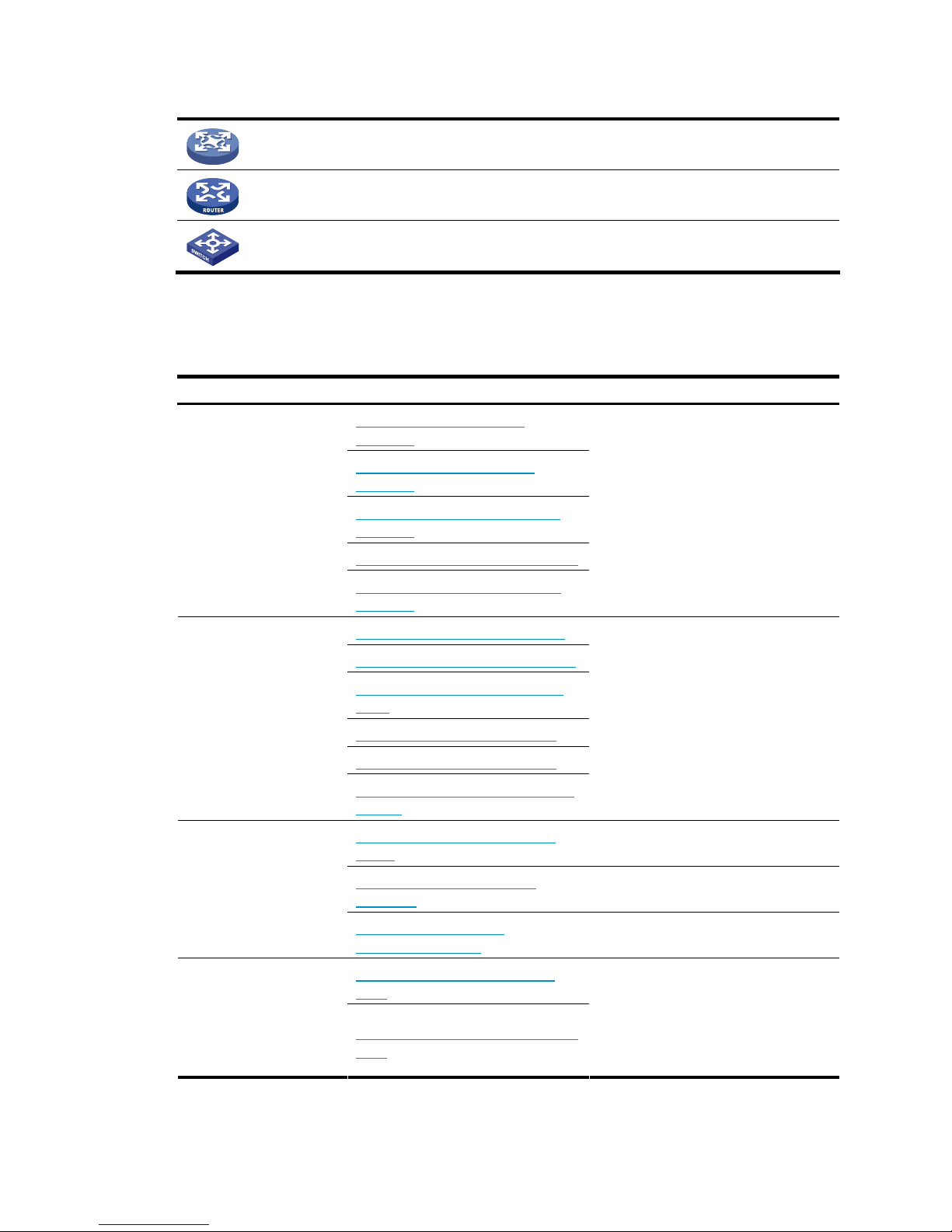
Network topology icons
Represents a generic network device, such as a router, switch, or firewall.
Represents a routing-capable device, such as a router or Layer 3 switch.
Represents a generic switch, such as a Layer 2 or Layer 3 switch, or a router that supports
Layer 2 forwarding and other Layer 2 features.
About the H3C MSR documentation set
The H3C MSR documentation set includes:
Category Documents Purposes
MSR 900 Routers Marketing
brochures
MSR 20-1X Routers Marketing
brochures
MSR 20-2X[40] Routers Marketing
brochures
MSR 30 Routers Marketing brochures
Product description and
specifications
MSR 50-40[60] Routers Marketing
brochures
Describe product specifications and
benefits.
MSR 900 Routers Installation guide
MSR 20-1X Routers Installation guide
MSR 20-2X[40] Routers Installation
guide
MSR 30 Routers Installation guide
MSR 50 Routers Installation guide
Hardware specifications
and installation
MSR Series Routers Interface Module
Manual
Provides a complete guide to hardware
installation and hardware
specifications.
MSR Series Routers Configuration
guides
Describe software features and
configuration procedures.
MSR Series Routers Command
references
Provide a quick reference to all
available commands.
Software configuration
MSR Series Routers Web
Configuration guides
Describe Web software features and
configuration procedures.
MSR Basic Series Routers Release
notes
Operations and
maintenance
MSR Standard Series Routers Release
notes
Provide information about the product
release, including the version history,
hardware and software compatibility
matrix, version upgrade information,
technical support information, and
software upgrading.

Obtaining documentation
You can access the most up-to-date H3C product documentation on the World Wide Web at
http://www.h3c.com.
Click the links on the top navigation bar to obtain different categories of product documentation:
[Technical Support & Documents > Technical Documents] – Provides hardware installation, software
upgrading, and software feature configuration and maintenance documentation.
[Products & Solutions] – Provides information about products and technologies, as well as solutions.
[Technical Support & Documents > Software Download] – Provides the documentation released with the
software version.
Technical support
customer_service@h3c.com
http://www.h3c.com
Documentation feedback
You can e-mail your comments about product documentation to info@h3c.com.
We appreciate your comments.

i
Contents
Overview ······································································································································································ 1
Introduction ········································································································································································1
Hardware Specifications ·········································································································································1
MSR 50-40/50-60 Routers ·····································································································································2
Generic Modules·······························································································································································4
MPUF/MPU-G2 ························································································································································4
MSCA/MSCB························································································································································ 12
PSU ·········································································································································································13
FAN Module ··························································································································································13
SIC/DSIC and FIC/DFIC Interface Cards··········································································································· 14
ESM Module ·························································································································································· 14
Voice Module ························································································································································ 15
Installation Preparations ············································································································································16
Requirements on Environment ······································································································································· 16
Requirements on Temperature/Humidity ············································································································ 16
Requirements on Cleanness·································································································································· 16
Requirements on Electrostatic Discharge Prevention·························································································· 17
Requirements on Electromagnetic Environments ································································································17
Requirements on Preventing Lightning················································································································· 17
Requirements on Workbench······························································································································· 18
Safety Precautions·························································································································································· 18
Installation Tools, Meters and Equipments ··················································································································18
Installation···································································································································································20
Installation Process ·························································································································································20
Installing the Cabinet ····················································································································································· 20
Installing the Router························································································································································ 20
Installing the Router on a Workbench················································································································· 21
Installing the Router in a Cabinet ························································································································ 21
Installing Generic Modules ··········································································································································· 22
Connecting the PGND··················································································································································· 22
Connecting the Power Cord·········································································································································· 23
Power Input and PGND········································································································································ 23
Connecting the AC Power Cord ·························································································································· 23
Connecting the DC Power Cord ·························································································································· 24
Connecting the Console Terminal ································································································································ 25
Fixed Interfaces ······························································································································································26
Ethernet Interface··················································································································································· 26
Connecting AUX to a Modem······························································································································ 29
Interface Card Module ·················································································································································· 30
Installing/Removing Slide Rail······································································································································ 30
MSR 50 Slide Rail ················································································································································· 30
Installing Slide Rail ················································································································································31
Removing Slide Rail ··············································································································································32
Verifying Installation ······················································································································································ 33
Startup and Configuration·········································································································································34
Startup ·············································································································································································34
Setting up Configuration Environment ················································································································ 34

ii
Powering on the Router········································································································································· 36
Startup Process······················································································································································· 37
Configuration Fundamentals ·········································································································································38
Basic Configuration Procedures··························································································································· 38
Command Line Interface······································································································································· 38
Arranging Slots and Numbering Interfaces········································································································ 39
Software Maintenance···············································································································································41
Introduction ·····································································································································································41
Files········································································································································································· 41
Software Maintenance Methods·························································································································· 43
Maintaining Application Program and Configuration Through Command Lines···················································· 44
Maintaining the Router Through TFTP Server ····································································································· 44
Maintaining the Router Through FTP Server ······································································································· 47
BootWare Menu····························································································································································· 50
Main BootWare Menu·········································································································································· 50
BootWare Submenus ············································································································································ 52
Upgrading an Application Program Through an Ethernet Interface········································································· 55
Configuring Ethernet Interface Parameters ········································································································· 55
Upgrading Procedure ···········································································································································56
Upgrading BootWare Through Ethernet Interface······································································································ 58
Upgrading BootWare Through Serial Interface·········································································································· 58
XModem Protocol Overview ································································································································ 58
Modifying Serial Interface Parameters················································································································ 59
Upgrading BootWare··········································································································································· 60
Upgrading an Application Program through a Serial Interface················································································ 62
Maintaining Application and Configuration Files ······································································································ 62
Dealing with Password Loss·········································································································································· 64
User Password Loss ··············································································································································· 64
BootWare Password Loss ····································································································································· 65
Super Password Loss············································································································································· 65
Backing Up and Restoring BootWare·························································································································· 66
Hardware Maintenance ············································································································································67
Preparing Tools ······························································································································································ 67
Internal Structure····························································································································································· 67
Removing/Installing PSUs ············································································································································· 68
Removing a PSU ····················································································································································68
Installing a PSU······················································································································································ 69
Removing/Installing the Fan Module ···························································································································69
Removing the Fan Module···································································································································· 69
Installing the Fan Module ····································································································································· 70
Removing/Installing the MPUF ····································································································································· 70
Removing the MPUF ·············································································································································· 70
Installing the MPUF················································································································································ 71
Removing/Installing MSCA··········································································································································· 71
Removing MSCA ···················································································································································71
Installing MSCA····················································································································································· 71
Installing/Removing CF Card ······································································································································· 72
CF Card Structure·················································································································································· 72
Installing CF Card ················································································································································· 72
Removing CF Card················································································································································ 72
Replacing Memory Bar·················································································································································· 73
Memory Bar Structure ··········································································································································· 74
Memory Bar Slot···················································································································································· 74

iii
Installing/Removing Memory Bar························································································································ 74
Replacing VPM······························································································································································· 75
VPM Structure ························································································································································ 75
VPM Slot································································································································································· 76
Installing/Removing VPM ····································································································································· 76
Installing/Removing ESM/VCPM Card ······················································································································· 76
Troubleshooting··························································································································································78
Troubleshooting the Power System······························································································································· 78
Troubleshooting the Configuration System·················································································································· 78
Troubleshooting Application Software Upgrade ········································································································ 79
Index ···········································································································································································81

1
Overview
Introduction
MSR 50 Routers were self-developed by our company for use on enterprise-level networks. Depending on
the network size, MSR 50 Routers can be either core routers on small and medium enterprise networks,
or access routers for network branches on some large-sized enterprise networks. Therefore, MSR 50
Routers are suitable for the application on the carrier-level networks, such as telecom management
networks and billing networks. MSR 50 Routers adopt modular design and support a wide range of
optional interface cards and service modules, including flexible interface card (FIC), smart interface card
(SIC), multi-service card A (MSCA), multi-service card B (MSCB), enhanced service module (ESM), voice
processing module (VPM) and voice co-processing module (VCPM).
The MSR 50-40 routers are 3U in height and the MSR 50-60 are 4U in height. Slot 0 provided on the
front panel of both the two models is for the main control board, which can be MPUF or MPU-G2
respectively. MSCA or MSCB can be installed in the MSC slot provided on the backplane to provide a
variety of security and voice services, where MSCA works in conjunction with MPUF while MSCB works
with MPU-G2.
Base on power supply mode, the MSR 50-40 and MSR 50-60 each have three models: AC, DC, and PoE
power supply. You can choose to use a DC or AC power supply unit (PSU) as the system power supply,
or install two AC or two DC PSUs to form 1+1 redundancy backup. You can also install a PoE power
module to work in conjunction with the AC or DC PSU to provide remote power supply for powered
devices (PDs).
The PSUs, fan trays, and FICs of MSR 50 routers are all hot swappable.
Currently, the MSR 50 include these models:
• MSR 50-40
• MSR 50-60
Hardware Specifications
Table 1 Hardware specifications for the MSR 50-40/50-60 routers
Item MSR 50-40 MSR 50-60
FIC module 4 6
MSC module 1 1
Processor PowerPC PowerPC
Boot ROM 4 MB 4 MB
Memory
DDR SDRAM:
Default: 512 MB
Max: 1 GB
DDR SDRAM:
Default: 1 GB
Max: 2 GB
CF card
Default: 256 MB
Max: 1 GB
Default: 256 MB
Max: 1 GB
2
Item MSR 50-40 MSR 50-60
Dimensions (H × W × D)
(excluding feet and rack-mounting ear)
130.7 × 436.2 × 424 mm (5.15
× 17.17 × 16.70 in.)
175.1 × 436.2 × 424 mm
(6.89 × 17.17 × 16.69 in.)
Weight 18 kg (39.68 lb.) 20 kg (44.09 lb.)
AC input Rated voltage: 100 VAC to 240 VAC; 50 Hz/60 Hz
DC input Rated voltage: –48 VDC to –60 VDC
PoE input
100 VAC to 240 VAC, 50 Hz or 60 Hz, or
–48 VDC to –60 VDC
Max power 500 W
Operating temperature 0°C to 40°C (32°F to 104°F)
Relative humidity (noncondensing) 5% to 90%
NOTE:
• Boot ROM stores the Bootstrap for booting the router.
• Communication data between the system and the CPU is stored in the memory when the system is
running.
• The CF card is used to store the software system and configuration file. The CF card LED blinks when the
system is reading/writing data from/to the CF card. In this case, do not remove the CF card; otherwise
hardware and software damage may occur.
MSR 50-40/50-60 Routers
Appearance
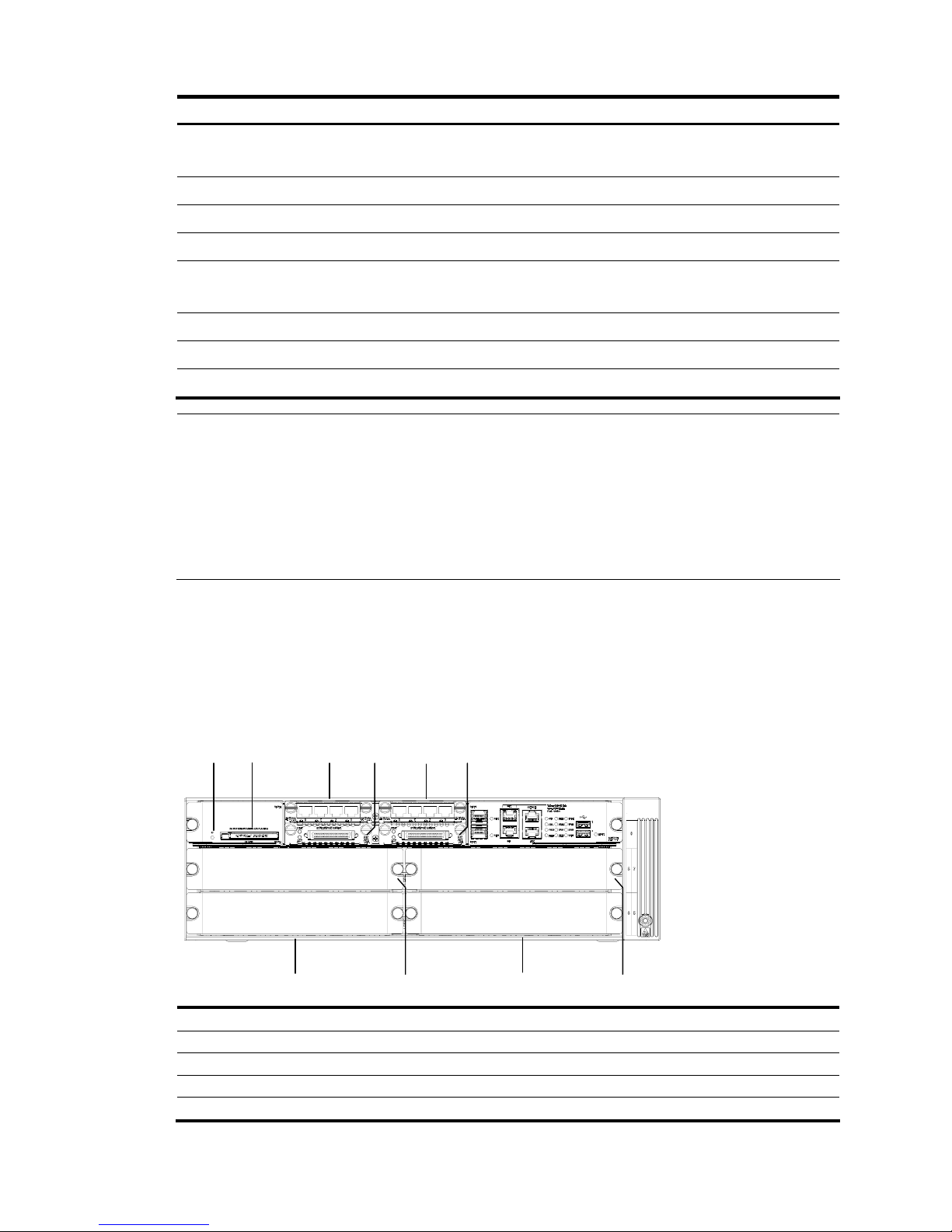
1. Front view of an MSR 50-40
Figure 1 Front panel of an MSR 50-40
(1) (2) (3)(4) (5)(6)
(7)
(8) (10) (9)
(1) CF card LED (2) CF card
(3) SIC slot 1 (4) SIC slot 2
(5) SIC slot 3 (6) SIC slot 4
(7) FIC slot 5 (8) FIC slot 6
(9) FIC slot 7 (10) FIC slot 8
3
2.
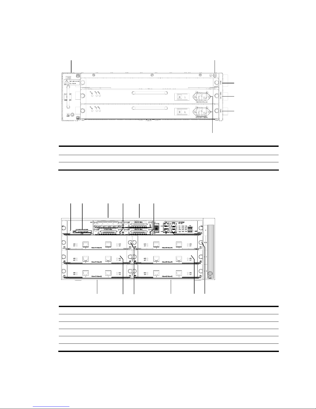
Rear view of an MSR 50-40
Figure 2 Rear view of an MSR 50-40
(1)
(3)
(2)
(5)(6)
(4)
(1) MSC slot (2) System power 1 slot
(3) System power 0 slot (4) System power socket
(5) Grounding terminal (6) Fan slot
3. Front view of an MSR 50-60
Figure 3 Front panel of an MSR 50-60
(1) (2) (3)(4) (5)(6)
(7)(8) (10)
(9) (11)
(12)
(1) CF card LED (2) CF card
(3) SIC slot 1 (4) SIC slot 2
(5) SIC slot 3 (6) SIC slot 4
(7) FIC slot 5 (8) FIC slot 6
(9) FIC slot 7 (10) FIC slot 8
(11) FIC slot 9 (12) FIC slot 10
4
4.
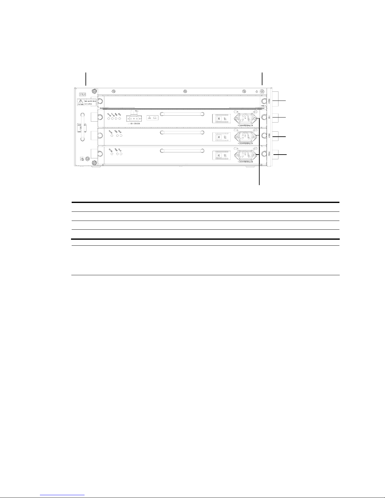
Rear view of an MSR 50-60
Figure 4 Rear view of an MSR 50-60
(1)
(3)
(2)
(6)(7)
(5)
(4)
(1) MSC slot (2) System power 2 slot (PoE)
(3) System power 1 slot (4) System power 0 slot
(5) System power socket (6) Grounding terminal
(7) Fan slot
NOTE:
The figures above illustrate the components of a router with MPUF installed. No SIC slots are provided if
an MPU-G2 is applied on the router.
Generic Modules
The MSR 50 is available with generic modules such as SIC and FIC interface cards. For detailed
information about interface cards, refer to MSR Series Routers Interface Module Manual.
For the types of interface modules that each model of the MSR 50 routers can accommodate, refer to
Appendix A Interface Card and Interface Module Purchase Guide in the MSR Series Routers Interface
Module Manual.
Currently, the MSR 50 routers primarily support the main boards MPUF and MPU-G2. See details as
follows.
MPUF/MPU-G2
Functions
As the core of the router, the MPUF/MPU-G2 functions to process protocols, forward low-speed packets,
govern interfaces, and detect faults. You can gather information about the operating state of FAN module,
PSU, and system by reading their corresponding LEDs on the main control board; alternatively, you can
monitor state using a network management system. In addition, the main control board provides a
hardware reset button: RESET. Each MPUF provides four SIC slots for extending the access capabilities.
An MPU-G2 delivers improved process capabilities without offering any SIC slots.
5
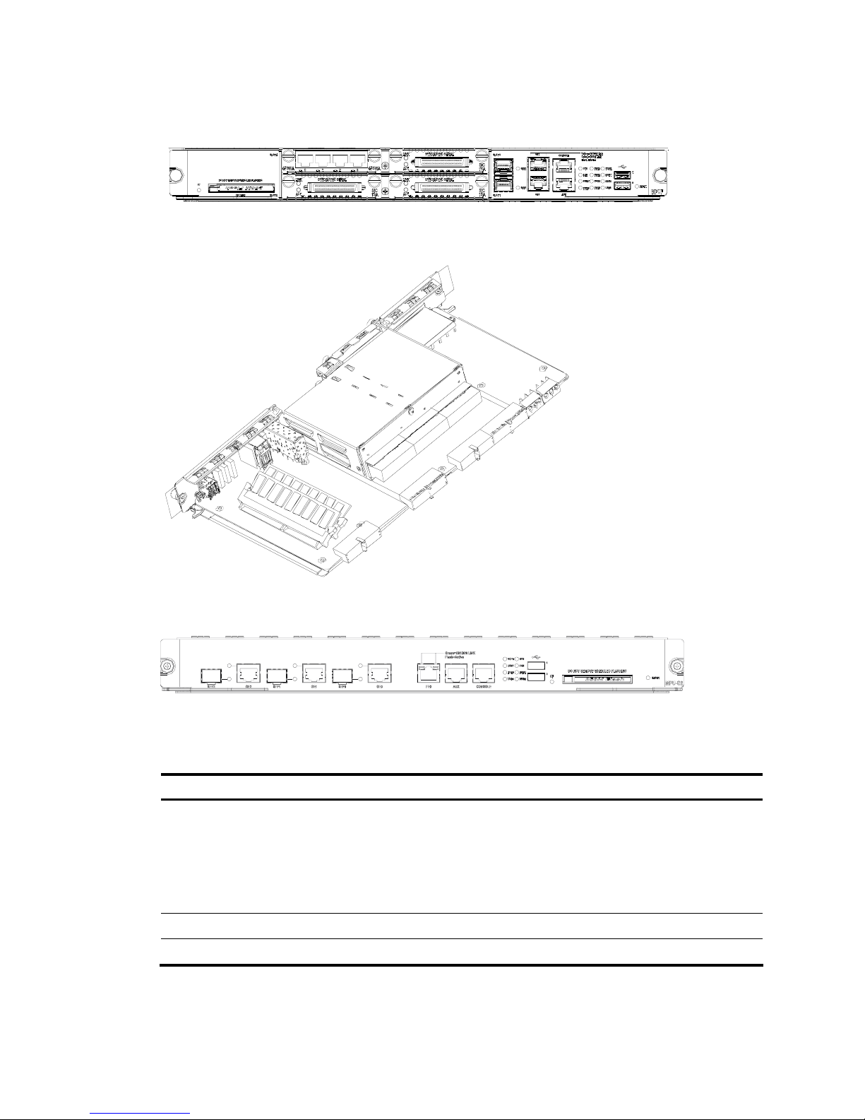
Appearance
Figure 5 MPUF front view
Figure 6 MPUF internal structure
Figure 7 MPU-G2 internal structure
Specifications
Table 2 Technical specifications for MPUF/MPU-G2
Item MPUF MPU-G2
Interfaces
2 GE Combo interfaces
1 AUX port
1 console port
2 USB interfaces
3 GE Combo interfaces
1 AUX port
1 console port
2 USB interfaces
1 management FE interface
Processor 833 MHz 1700 MHz
Flash 4 MB 4 MB

6
Item MPUF MPU-G2
Memory
DDR SDRAM
Default: 512 MB
Max: 1 GB
DDR II
Default: 1 GB
Max: 2 GB
CF Card
Default: 256 MB
Max: 1 GB
Default: 256 MB
Max: 1 GB
Slot 4 SIC slots —
NOTE:
• DDR SDRAM (synchronous dynamic random access memory) is the memory, which provides software
operation environment.
• CF card functions as the major file storage medium to store application program files, anomaly
information, and configuration files.
• Boot ROM stores the Bootstrap for booting the router.
• Do not unplug the USB device during USB data transmission; otherwise, data loss or even hardware
failures may occur.
• The USB interface does not support hot-swapping of USB modems from Sierra Wireless.
LED and interface
Figure 8 LEDs and interfaces on an MPUF
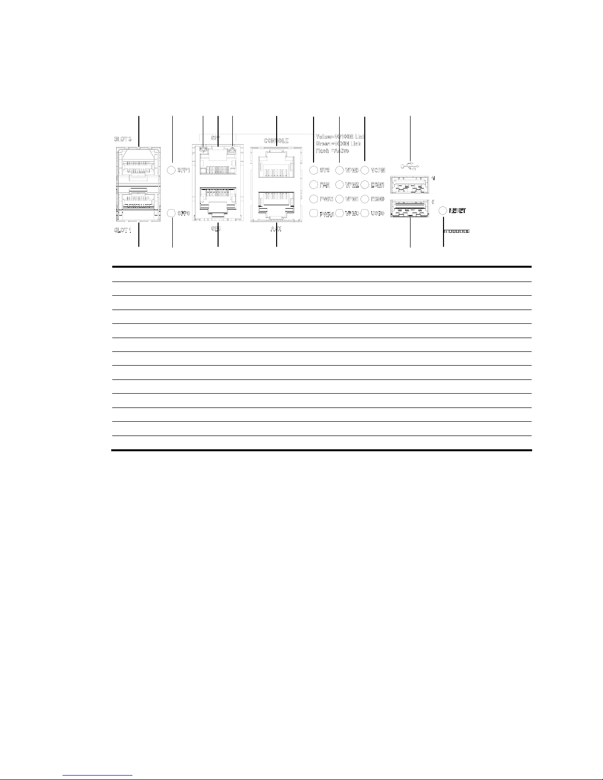
7
Figure 9 Big view of the LEDs and interfaces on an MPUF
(1)
(2)
(3)
(4)
(5)
(6)
(7)
(8)
( 9 )
(10)
(11)
(12)
(13)
(15)
(16)
(17)
(18)(14) (19)
(20)
(22)
(21)(23)
(24)
(25)
(1) System LED (SYS) (2) Fan LED (FAN)
(3) Power LED 1 (PWR1) (4) Power LED 0 (PWR0)
(5) VPM LED 3 (VPM3) (6) VPM LED 2 (VPM2)
(7) VPM LED 1 (VPM1) (8) VPM LED 0 (VPM0)
(9) VCPM LED (VCPM) (10) ESM LED 1 (ESM1)
(11) ESM LED 0 (ESM0) (12) USB Slave LED (USB0)
(13) Fixed gigabit electrical interface 0 LED (14) Fixed gigabit electrical interface 1 LED
(15) Fixed gigabit optical interface 0 LED (16) Fixed gigabit optical interface 1 LED
(17) USB interface 0 (18) USB interface 1
(19) Console port (CONSOLE) (20) Auxiliary port (AUX)
(21) Fixed gigabit electrical interface 0 (22) Fixed gigabit electrical interface 1
(23) Fixed gigabit optical interface 0 (24) Fixed gigabit optical interface 1
(25) RESET LED
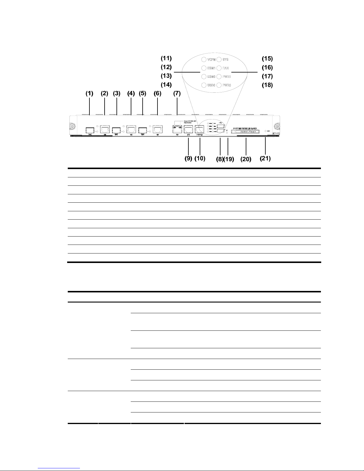
8
Figure 10 Big view of the LEDs and interfaces on an MPU-G2
(1) Fixed gigabit optical interface 2 (2) Fixed gigabit electrical interface 2
(3) Fixed gigabit optical interface 1 (4) Fixed gigabit electrical interface 1
(5) Fixed gigabit optical interface 0 (6) Fixed gigabit electrical interface 0
(7) Fixed 100 Mbps electrical interface 0 (8) USB interface
(9) Auxiliary port (AUX) (10) Console port (CONSOLE)
(11) VCPM LED (VCPM) (12) ESM LED 1 (ESM1)
(13) ESM LED 0 (ESM0) (14) USB Slave LED (USB0)
(15) System LED (SYS) (16) Fan LED (FAN)
(17) Power LED 1 (PWR1) (18) Power LED 0 (PWR0)
(19) CF card LED (20) CF card
(21) RESET LED
1. LED attributes
Table 3 LED attributes
LED Color Status Meaning
Off No power input, or the main control board has failed.
Green, blinking (0.5
Hz)
The interface card is running as configured.
Green, blinking (4
Hz)
The system is being booted.
SYS
Green &
yellow
Yellow The system has failed.
Off Power 1 is not present.
Steady green Power 1 is present and working normally.
PWR0
Green &
yellow
Yellow Power 1 has failed.
Off Power 2 is not present.
Steady green Power 2 is present and working normally.
PWR1
Green &
yellow
Yellow Power 2 has failed.

9
LED Color Status Meaning
Off The FAN module is not present.
Steady green The FAN module is working normally.
FAN
Green &
yellow
Yellow The FAN module has failed.
Off VPMx is not present.
Steady green VPMx is present,
VPM
0-3
Green &
yellow
Yellow VPMx has failed.
Off ESMx is not present.
Steady green ESMx is present.
Green, blinking ESMx is processing services.
ESM0-1
Green &
yellow
Yellow ESMx has failed.
Off VCPM is not present.
Steady green VCPM is present and operating normally.
VCPM
Green &
yellow
Yellow VCPM has failed.
Off No LINK.
Green SFP optical module gigabit LINK
Green, blinking SFP optical module is transmitting or receiving data.
SFP0-1
Green &
yellow
Yellow SFP has not passed the test.
Off No CF card.
Steady green CF card is present, and can be identified by the router.
Green, blinking
The system is accessing the CF card (In this case, the card
cannot be removed).
CF
Green &
Yellow
Yellow CF card cannot be identified by the router.
Off USB is not connected to HOST.
Steady green USB is connected to HOST, when it can be removed.
USB0 Green
Green, blinking USB is transmitting data, when it cannot be removed.
Off No connection is established.
Green 1000 Mbps connection is established.
Green, blinking Active. The GE interface is transmitting or receiving data.
Yellow 10/100 Mbps connection is established.
GE
Green &
yellow
Yellow, blinking Active. The GE interface is transmitting or receiving data.
Green, off No connection is established.
Steady green A connection is established.
Yellow, off No data is being transmitted or received.
FE
Green/yell
ow
Yellow, blinking Data is being transmitted or received.
RESET — — Reset button

10
2.
Console port
Table 4 Console port attributes
Attribute Description
Connector RJ-45
Interface standard RS232
Baud rate
9600 bps to 115200 bps
9600 bps (default)
Function
Connecting to the ASCII terminal
Connecting to the serial interface of the local PC and running terminal
emulation program on the PC.
Command line interface
3. AUX port
Table 5 AUX port attributes
Attribute Description
Connector RJ-45
Interface standard RS232
Baud rate 300 bps to 115200 bps
Function
Modem dialup
Backup
4. Ethernet interface
The MPUF provides 10/100/1000 Mbps Ethernet interfaces that each accommodates an RJ-45
connector and a small form-factor pluggable (SFP) module respectively for electrical and optical
connections. But you can use only one connection at a time.
Five types of 1000Base-FX SFP transceiver modules are available: multi-mode short-haul (850 nm),
single-mode medium-haul (1310 nm), single-mode long-haul (1310 nm), single mode long-haul (1550 nm),
and single-mode ultra-long haul (1550 nm). They all provide LC interfaces and are hot swappable.
The attributes are listed in the following table:
Table 6 1000 Mbps Ethernet electrical interface attributes
Attribute Description
Connector RJ-45
Interface MDI/MDIX auto-sensing
Frame format
Ethernet_II
Ethernet_SNAP
Operating mode
10/100/1000 Mbps auto-sensing
Full duplex/half duplex
(1000 Mbps and half duplex cannot be configured together.)

11
Table 7 1000 Mbps Ethernet optical interface attributes
Description
Attribute
Multi-mode
short-haul (850
nm)
Single-mode
medium-haul
(1310 nm)
Single-mode
long-haul
(1310 nm)
Single-mode
long-haul
(1550 nm)
Single-mode
ultra-long
haul (1550
nm)
Connector SFP/LC
Optical fiber
62.5/125 μm
multi-mode
9/125 μm
single-mode
9/125 μm
single-mode
9/125 μm
single-mode
9/125 μm
single-mode
Max. transmission
segment
0.55 km (0.34
mi)
10 km (6.21
mi)
40 km (24.86
mi)
40 km (24.86
mi)
70 km (43.50
mi)
Central
wavelength
850 nm 1310 nm 1310 nm 1550 nm 1550 nm
Min –9.5 dBm –9 dBm –2 dBm –4 dBm –4 dBm
Transmitt
er optical
power
Max 0 dBm –3 dBm 5 dBm 1 dBm 2 dBm
Receiver sensitivity –17 dBm –20 dBm –23 dBm –21 dBm –22 dBm
Operating mode
1000 Mbps
Full duplex
Frame format
Ethernet_II
Ethernet_SNAP
NOTE:
The fiber-optic and electrical connections that a 10/100/1000 Mbps Ethernet interface provides canno
t
be used at the same time. If both connections are present, you can configure which connection takes effec
t
through commands. By default, the electrical connection works.
5. Compact Flash (CF) slot
The MPUF provides one CF (PCMCIA) slot for a hot swappable CF card.
A CF card can store application programs, configuration files, and log information. With it, you can
conveniently perform such operations as online upgrade and log management.
CAUTION:
Do not remove a CF card during its read or write operation; otherwise, data loss and even hardware
damage will occur.
6. USB interface
MPUF provides two USB 1.1 interfaces: USB1 for Host and USB0 for Host and Slave that can be
configured. USB LED is valid only when USB0 is set to Slave.
12
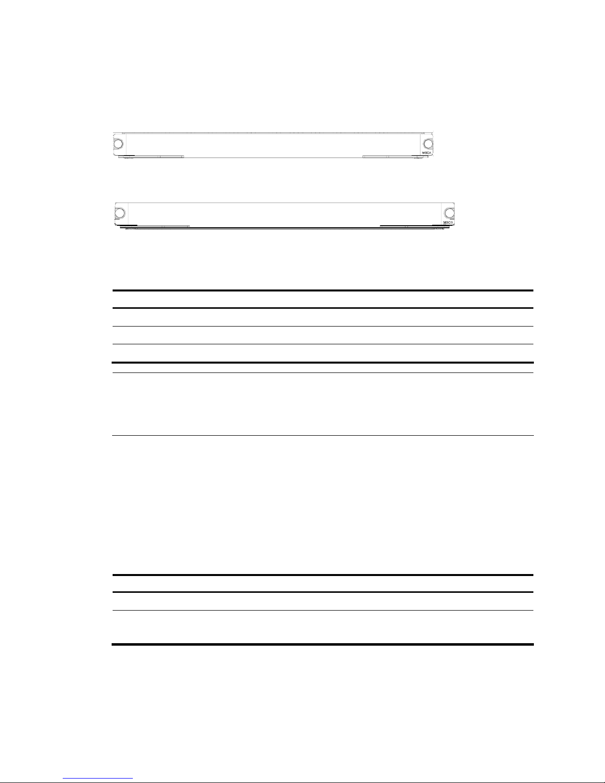
MSCA/MSCB
Appearance
Figure 11 MSCA front view
Figure 12 MSCB front view
Specifications
Table 8 MSCA/MSCB specifications
Item MSCA MSCB
ESM slot 2 2
VCPM slot 1 1
VPM slot 4 0
NOTE:
• MSC (multi-service card) is installed in the slot provided on the backplane of the MSR 50 routers to carr
y
various service modules.
• MSCA is designed to work with MPUF while MSCB must be applied with MPU-G2.
ESM module
Installed on an MSC, ESM module supports IPSec and by using hardware encryption expedites IP packet
encryption. The use of hardware encryption/decryption and hashing operation allows the router to
encrypt packets with high performance and reliability.
The encryption card is optional. On a router installed with an encryption card, the main control board
functions to route IP packets and implement encryption-enabled VPN, while the encryption card functions
to encrypt packets.
Table 9 Encryption card attributes
Attribute Description
Protocol IPSec
Hardware encryption algorithm
Key algorithms: DES, 3DES, AES
Authentication algorithms: HMAC-MD5-96, HMAC-SHA-1-96
VPM and VCPM modules
VPM (Voice Processing Module) functions to coding/decoding, EC and CNG of voices.
VCPM (Voice Co-Processing Module) processes the voice data together with VPM.
13
PSU
Functions
The power supply system of the MSR 50 can work in either single-power or dual-power mode. In
dual-power mode, the two PSUs (DC-input or AC-input) function in redundancy backup mode. That
means, when a PSU fails or its power supply is disconnected, another PSU can still work and supply all
the power required by the system.
You can connect a PSU to the backplane by inserting it from the rear of the router chassis. It is hot
swappable and its switchover does not affect the ongoing system operation.
NOTE:
• When installing your router in a communications equipment room, ensure that the AC power
distribution cabinet can provide a li
g
htning protection box or arrester against the current of 20 KA and
above.
• MPU-G2 does not support any PoE power module.
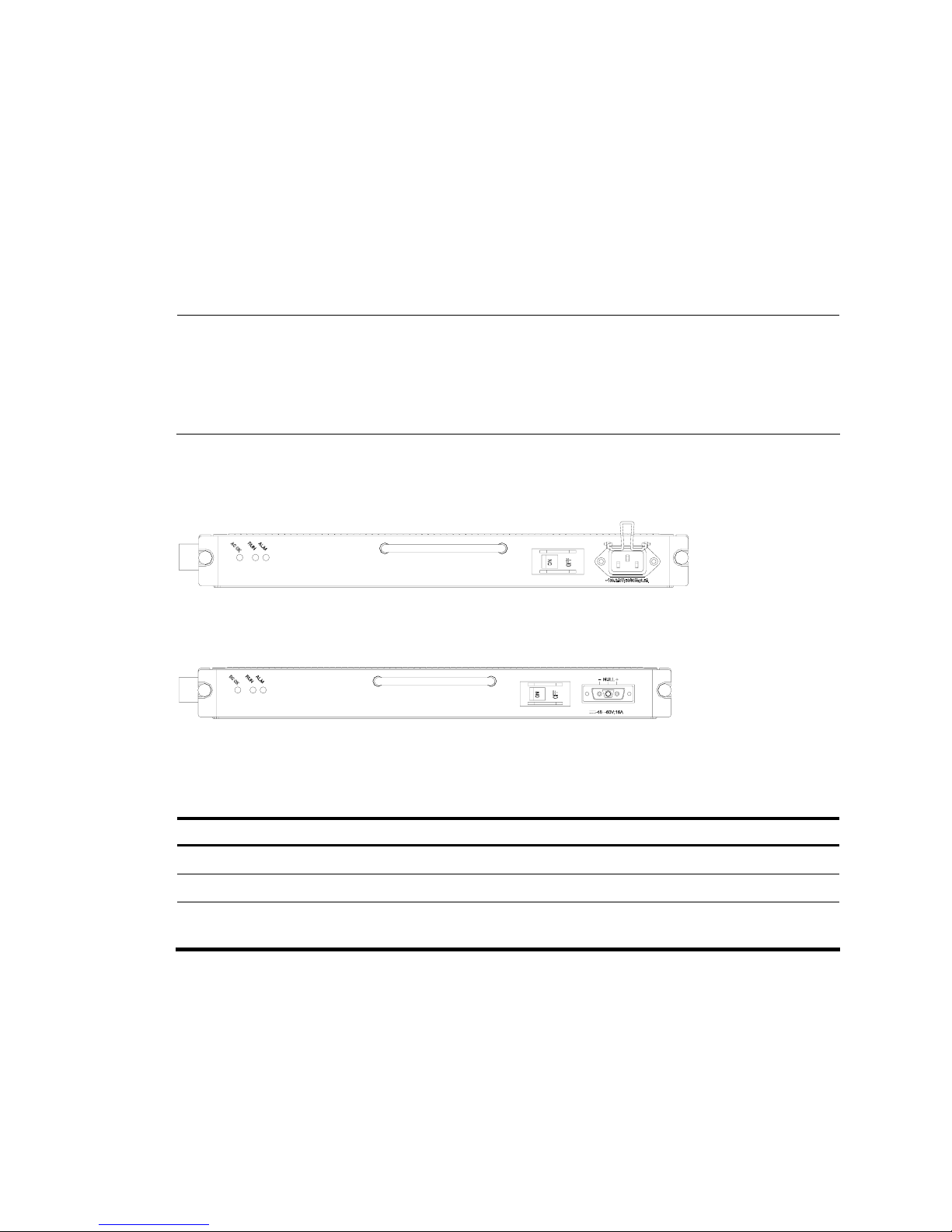
Appearance
Figure 13 AC-input PSU
Figure 14 DC-input PSU
LED
Table 10 PSU LED description
LED Meaning
ALM (red) ON means the PSU is not well-seated or has failed.
RUN (green) Steady ON means the PSU is operating normally, and OFF means the PSU has failed.
AC/DC OK (green)
PSU input LED. Steady ON means the normal voltage is inputting, and OFF means the
opposite.
FAN Module
Functions
The MSR 50-40 is configured with six fans; the MSR 50-60 is configured with eight fans. These fans are
working in pairs and the two fans in each pair are working in redundancy. When all these fans are
working normally, the operating temperature of the system can be maintained between 0°C and 55°C
(32°F to 131°F). As the failure of a fan does not affect the operation of other fans, the normal operating
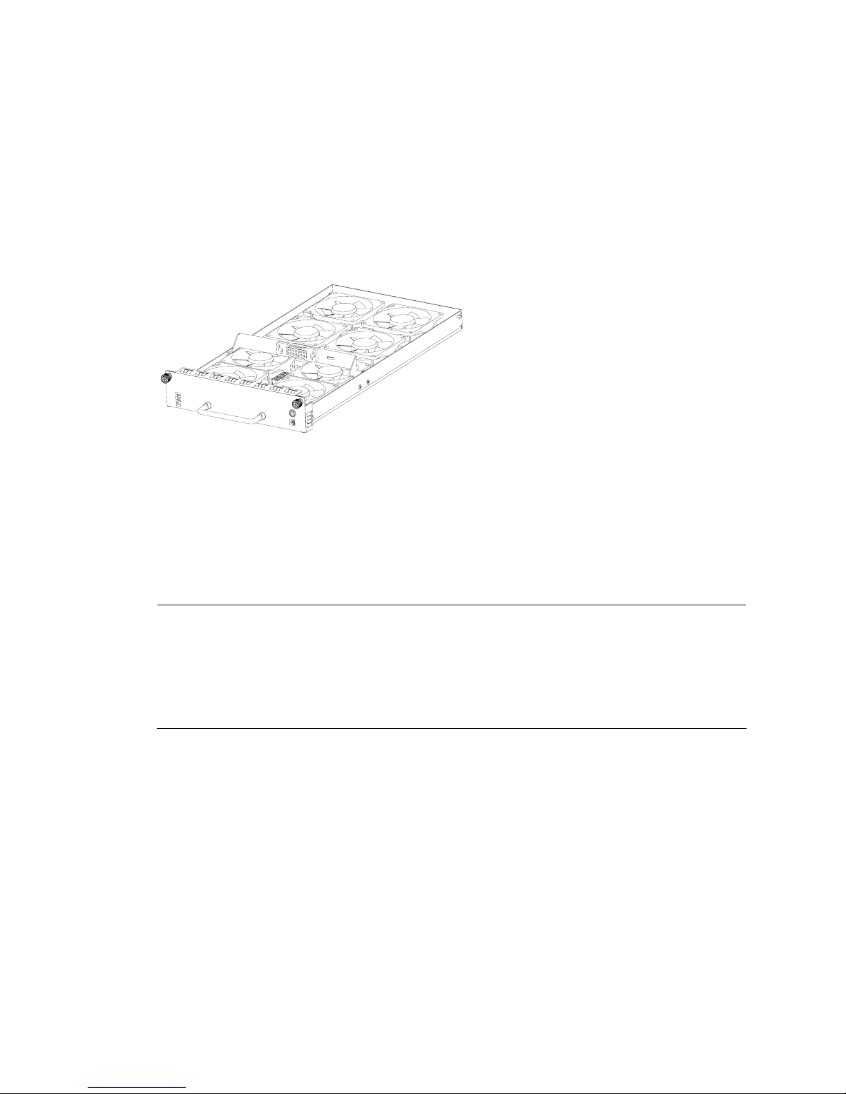
14
temperature of the system can maintain. The routing speed of the fans is adjusted by the fan controller on
the main control board and between 50% and 100% depending on the system temperature. When the
system temperature rises above the high-temperature threshold set by the fan controller, the fans are
rotating at full speed (100%); when the system temperature drops below the low-temperature threshold,
the fans are rotating only at half of the speed (50%). When a fan stops rotating, the fan controller alarms.
The alarm and state LEDs of the FAN are located on the front panel of MPUF.
Appearance
The following figure shows a FAN module, taking MSR 50-60 for example.
Figure 15 FAN module (the MSR 50-60)
SIC/DSIC and FIC/DFIC Interface Cards
MSR 50 routers adopt modular design and support a wide range of optional SIC/DSIC and FIC/DFIC
interface cards, providing various interfaces, such as synchronous/asynchronous serial interface,
Ethernet interface, E1/T1, ISDN BRI/PRI, ADSL, audio interface, Layer 2 switching interface, and so on.
For details about the interface cards, refer to MSR Series Routers Interface Module Manual.
NOTE:
• For an MSR 50 router, SIC-4FSW/1FEA/1GEC/1ADSL/1ADSL-I can only be installed in Slot 2 or Slo
t
4 on the MPUF.
• Interface cards that support PoE can be used for remote power supply only if they are installed on the
PoE models; otherwise, the interface cards that support PoE can only function as normal switching
modules if they are used on non-PoE models.
ESM Module
• High-performance network data encryption ESM module (ESM-ANDE)
• Standard network data encryption ESM module (ESM-SNDE)
ESM module supports IPSec and by using hardware encryption expedites IP packet encryption. The use
of hardware encryption/decryption and hashing operation allows the router to encrypt packets with high
performance and reliability.
The encryption card is optional. On a router installed with an encryption card, the main control board
functions to route IP packets and implement encryption-enabled VPN, while the encryption card functions
to encrypt packets.

15
Table 11 Encryption card attributes
Attribute Description
Protocol IPsec
Hardware encryption algorithm
Key algorithms: DES, 3DES, AES
Authentication algorithms: HMAC-MD5-96, HMAC-SHA-1-96
Voice Module
VPM (Voice Processing Module) functions to implement the encryption/decryption, EC and CNG of
voices.
VCPM (Voice Co-Processing Module) processes the voice data together with VPM.
• Voice co-processing module (RT-VCPM)
• 8-channel voice processing module (RT-VPM8)
• 16-channel voice processing module (RT-VPM16)
• 24-channel voice processing module (RT-VPM24)
• 32-channel voice processing module (RT-VPM32)

16
Installation Preparations
Requirements on Environment
The MSR 50 routers are designed for indoor applications. To ensure the normal operation and prolong
their service life, the following requirements for installation site must be met.
Requirements on Temperature/Humidity
To ensure the normal operation and prolong their service life, certain requirements on temperature and
humidity in the equipment room shall be met. If the relative humidity is too high, the insulation materials
in it will deteriorate easily or even lead to electric leakage. Sometimes this will result in change to the
mechanical performance of the materials and rusting of the metal components. If the relative humidity is
too low, the fastening screw will become loosen due to shrinkage of the isolation spacer. In an
environment with dry climate, static electricity may be produced, putting the CMOS of the router to risk.
High temperature is of the greatest risk: for it will significantly degrade the router’s reliability, speed up
aging process of the insulating materials, and shorten the service life of the router.
The requirements on the temperature and humidity for MSR 50 are shown in the following table:
Table 12 Temperature/humidity requirements in the equipment room
Temperature Relative humidity (noncondensing)
0°C to 40°C (32°F to 104°F) 5% to 90%
Requirements on Cleanness
Dust is harmful to the safe operation of the Router. Dust on the chassis may resu lt in static absorption, t hus
causing poor contact of the metal connection components or points. Especially under the condition of
low indoor humidity, dust is easier to be absorbed.
The requirements on the dust concentration and diameter are shown in the following table:
Table 13 Limitation on dust content in equipment room
Diameter (μm) 0.5 1 3 5
Concentration (particle/m³) 1.4 × 10⁷ 7 × 10⁵ 2.4 × 10⁵ 1.3 × 10⁵
Besides the dust specifications, the equipment room of the Router should also meet the rigorous
requirements for the content of salt, acid and sulfide. These harmful gases could accelerate the metal
erosion and aging process of some parts. The specific limits of these harmful gases as SO
2
, H2S, NO2,
NH
3
and CI2 are given in the following table.

17
Table 14 Limitation on harmful gases in equipment room
Gas Max. (mg/m
3
)
SO2 0.2
H2S 0.006
NH3 0.05
Cl2 0.01
Requirements on Electrostatic Discharge Prevention
Although many antistatic considerations have been given to MSR 50, damage to the router’s circuit or
even the whole equipment may still happen when the static electricity exceeds the tolerance threshold.
In the communication network to which the routers are connected, static induction mainly comes from two
aspects: external electric fields such as outdoor high voltage power line or thunder and internal
environment like flooring materials or the whole equipment structure. Thus, the following should be
considered to safeguard the equipment against the ESD.
• Make sure that the equipment and the floor are well grounded.
• The equipment room is dust-proof.
• Maintain an appropriate humidity and temperature.
• Wear an ESD-preventive wrist strap and uniform when contacting the circuit board.
• Place the removed circuit board on the antistatic workbench, with its face upward, or put it into the
static shielding bag.
• When observing or moving the removed circuit board, please touch the edge of the circuit board,
and avoid contacting the devices on it.
Requirements on Electromagnetic Environments
The interference sources, no matter where they come from, affect the routers with capacitance coupling,
inductance coupling, radiation of electromagnetic wave, common impedance (including the grounding
system) or conducting line (power line, signal line and transmission line etc.). So the following should be
considered:
• Take effective measures to prevent the power system from being interfered with by the power grid
system.
• Use an earthing system or lightning protection grounding different from that for the power supply
equipment and keep them as far as possible.
• Keep the router far away from the radio launcher, radar launcher, and high-frequency devices
working in high current.
• Use electromagnetic shielding when necessary.
Requirements on Preventing Lightning
Although many measures have been taken to protect MSR 50 from lightning, if the lightning intensity
exceeds a certain range, damage to the router may still happen. To protect the router from lightning
better, the following should be considered:
• Ensure the PGND wire of the chassis is well grounded.

18
• Ensure the ground point of the socket of AC power supply is well grounded.
• To enhance the lightning protection capability of the power supply, a lightning arrester could be
installed at the input end of the power supply.
• As for the signal line outdoors to which the interface modules of MSR 50 routers are connected,
such as ISDN line, telephone line, E1/T1 line, etc, a special lightning arrester should be installed
at the input end of the signal line to enhance the lightning protection capability.
Requirements on Workbench
When installing MSR 50 Routers, observe the following:
• There is spacing reserved at the air inlet and outlet in the router so as to facilitate the radiation of
the router cabinet.
• Make sure that the rack has a good ventilation system.
• Make sure that the rack is sturdy enough to support the weight of the device and the installation
accessories.
• Make sure that the rack is well-grounded.
Safety Precautions
When reading this manual, please pay attention to the following:
WARNING: indicates that this operation is incorrect and may seriously damage the router or
endanger the operator. Please follow the correct operation procedures for sake of safety.
CAUTION: indicates that during the installation and usage of the router, the operation needs
attention. If this operation is performed incorrectly, it might affect the operation of the router.
When installing or working on the router, you are recommended to:
• Keep the router far away from the heat sources and water/liquid.
• Make sure that the router has been correctly grounded.
• Wear an ESD-preventive wrist strap in installation and maintenance, making sure that the strap has
good skin contact.
• Do not hot swap the interface modules and interface cards of the router.
• Do not hot swap any cable.
• Correctly connect the interface cable for the router. Do not connect the telephone cable (including
the ISDN cable) to the AUX port or the console port.
• Use laser with caution. Do not directly stare into apertures or fiber-optic connectors that emit laser
radiation.
• Adopt uninterrupted power supply (UPS).
Installation Tools, Meters and Equipments
Tools
• Phillips screwdriver
• Straight screwdriver
• ESD-preventive twist strap

19
Cables
• PGND wire and power cord
• Console cable
• Optional cables
Meters and equipment
• Hub or LAN switch
• Console terminal (it could be a PC)
• Equipment related to the selected modules
• Multimeter
CAUTION:
None of the above-mentioned installation tools, meters, and equipment is shipped with MSR 50 routers.
 Loading...