

H3C MSR 30-11, MSR 30-16, MSR 30-20, MSR 30-40, MSR 30-60, MSR 30-11, MSR 30-16, MSR 30-20, MSR 30-40 User Manual
...
H3C MSR 30 Series Routers
Installation Manual
Hangzhou H3C Technologies Co., Ltd.
http://www.h3c.com
Manual Version: T2-08047L-20081106-C-1.03

Copyright © 2006-2008, Hangzhou H3C Te chnologie s Co., Ltd . and it s licen sors
All Rights Reserved
No part of this manual may be reproduced or transmitted in any form or by any means without prior
written consent of Hangzhou H3C Technologies Co., Ltd.
Trademarks
H3C, , Aolynk, , H3Care,
SecPro, SecPoint, SecEngine, SecPath, Comware, Secware, Storware, NQA, VVG, V
XGbus, N-Bus, TiGem, InnoVision and HUASAN are trademarks of Hangzhou H3C Technologies Co.,
Ltd.
All other trademarks that may be mentioned in this manual are the property of their respective owners.
Notice
The information in this document is subject to change without notice. Every effort has been made in the
preparation of this document to ensure accuracy of the contents, but all statements, information, and
recommendations in this document do not constitute the warranty of any kind, express or implied.
Technical Support
customer_service@h3c.com
http://www.h3c.com
, TOP G, , IRF, NetPilot, Neocean, NeoVTL,
2
G, VnG, PSPT,

About This Manual
Organization
MSR 30 Series Routers Installation Manual is organized as follows:
Chapter Contents
1 Overview
2 Installation Preparation
3. Installation
4. Startup and Configuration
5. Software Maintenance
6. Hardware Maintenance
7. Troubleshooting Describes some problems that may arise and how to solve them.
Conventions
Briefly introduces the appearance, system description, as well as
the features and applications of the MSR 30 series.
Describes the requirements on installation site, the safety
recommendations before and during installation, and the required
tools.
Covers the procedures for installing the MSR 30 series, power cord
connection, AUX cable connection, Console cable connection,
Ethernet cable connection and Synchronous/asynchronous serial
interface cable connection.
Helps you get familiar with the basic knowledge of how to boot and
configure the MSR 30 series, including device startup, power-on,
and initialization of system files, and so on.
Introduces how to maintain BootROM menu and software of the
MSR 30 series.
Introduces how to install and remove SDRAM, ESM/VCPM card
and CF card of the MSR 30 series.
The manual uses the following conventions:
Command conventions
Convention Description
Boldface
italic
[ ] Items (keywords or arguments) in square brackets [ ] are optional.
{ x | y | ... }
[ x | y | ... ]
{ x | y | ... } *
[ x | y | ... ] *
&<1-n>
# A line starting with the # sign is comments.
The keywords of a command line are in Boldface.
Command arguments are in italic.
Alternative items are grouped in braces and separated by vertical bars.
One is selected.
Optional alternative items are grouped in square brackets and
separated by vertical bars. One or none is selected.
Alternative items are grouped in braces and separated by vertical bars.
A minimum of one or a maximum of all can be selected.
Optional alternative items are grouped in square brackets and
separated by vertical bars. Many or none can be selected.
The argument(s) before the ampersand (&) sign can be entered 1 to n
times.
GUI conventions
Convention Description
< > Button names are inside angle brackets. For example, click <OK>.
[ ]
/
Symbols
Window names, menu items, data table and field names are inside
square brackets. For example, pop up the [New User] window.
Multi-level menus are separated by forward slashes. For example,
[File/Create/Folder].
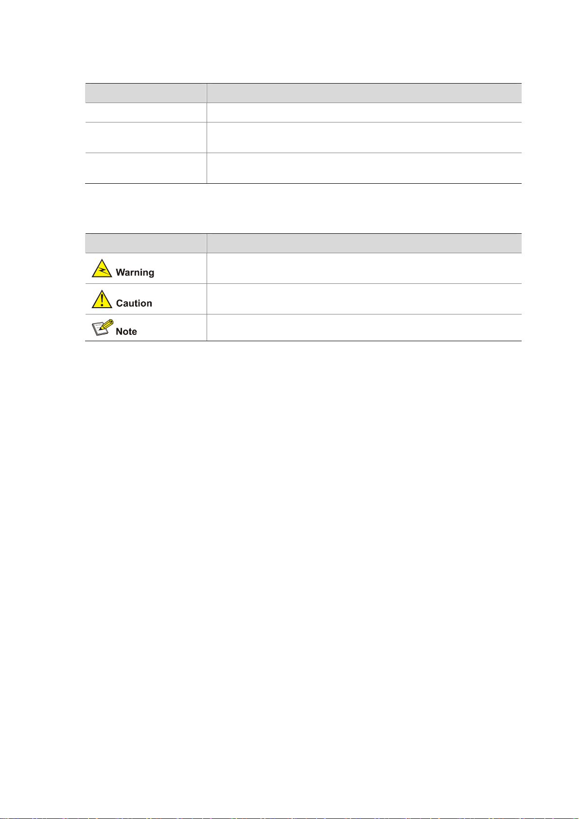
Convention Description
Means reader be extremely careful. Improper operation may cause
bodily injury.
Means reader be careful. Improper operation may cause data loss or
damage to equipment.
Means a complementary description.

Related Documentation
In addition to this manual, each MSR Series Routers documentation set includes the following:
Manual Description
MSR Series Routers User
Manual
It is a guide for the user to perform the operations correctly. It is
organized into the parts of getting started, system management,
interface, link layer protocol, network protocol, routing protocol,
multicast protocol, security, VPN, reliability, QoS, dial-up and VoIP,
as well as acronyms used in the manual.
It gives the user a detailed description of the operating commands.
It is organized into the parts of getting started, system
management, interface, link layer protocol, network protocol,
routing protocol, multicast protocol, security, VPN, reliability, QoS,
dial-up and VoIP, as well as a command index.
MSR Series Routers Interface
Card and Interface Module
Manual
MSR 20-1X Series Routers
Installation Manual
MSR 20 Series Routers
Installation Manual
MSR 50 Series Routers
Installation Manual
MSR 20-1x Series Routers
Web-Based Configuration
Manual
MSR 20/30/50 Series Routers
Web-Based Configuration
Manual
It covers the pinouts, function, interface attributes, panels and
LEDs of all interface cards and modules available with the router.
This guide describes the MSR 20-1X Series Routers and how to
install hardware, configure and boot software, and maintain
software and hardware. This guide also provides troubleshooting
and support information for your router.
This guide describes the MSR 20 Series Routers and how to in stall
hardware, configure and boot software, and maintain software and
hardware. This guide also provides troubleshooting and support
information for your router.
This guide describes the MSR 50 Series Routers and how to in stall
hardware, configure and boot software, and maintain software and
hardware. This guide also provides troubleshooting and support
information for your router.
It provides guidelines to Web-based configuration on the MSR
20-1x Series Routers.
It provides guidelines to Web-based configuration on the MSR
20/30/50 Series Routers.
Obtaining Documentation
You can access the most up-to-date H3C product documentation on the World Wide Web at this URL:
http://www.h3c.com.
The following are the columns from which you can obtain different categories of product docume ntation:
[Products & Solutions]: Provides information about products and technologies, as well as solutions.:
Provides information about products and technologies.
[Technical Support & Document > Technical Documents]: Provides several categories of product
documentation, such as installation, operation, and maintenance.
[Technical Support & Document > Product Support > Software]: Provides the documentation released
with the software version.
Documentation Feedback
You can e-mail your comments about product documentation to info@h3c.com.

We appreciate your comments.
Environmental Protection
This product has been designed to comply with the requirements on environmental protection. For the
proper storage, use and disposal of this product, national laws and regulations must be ob served.

Table of Contents
1 Overview.....................................................................................................................................................1-1
Introduction .............................................................................................................................................1-1
System Description.................................................................................................................................1-1
Fixed Interfaces...............................................................................................................................1-1
Interface Cards................................................................................................................................1-2
Processor and Memory...................................................................................................................1-2
Other Hardware Specifications........................................................................................................1-3
MSR 30-11 Router...........................................................................................................................1-3
MSR 30-16 Router...........................................................................................................................1-4
MSR 30-20 Router...........................................................................................................................1-6
MSR 30-40 Router...........................................................................................................................1-8
MSR 30-60 Router.........................................................................................................................1-10
Generic Modules...................................................................................................................................1-12
SIC/DSIC Cards ............................................................................................................................1-12
MIM/DMIM Cards ..........................................................................................................................1-13
ESM...............................................................................................................................................1-13
VPM/VCPM ...................................................................................................................................1-13
2 Installation Preparations...........................................................................................................................2-1
Requirements on Environment ...............................................................................................................2-1
Requirements on Temperature/Humidity ........................................................................................2-1
Requirements on Cleanness...........................................................................................................2-1
Requirements on Electrostatic Discharge Prevention.....................................................................2-2
Requirements on Electromagnetic Environments...........................................................................2-2
Requirements on Preventing Lightning...........................................................................................2-2
Requirements on Workbench..........................................................................................................2-3
Safety Precautions..................................................................................................................................2-3
Installation Tools, Meters and Equipments.............................................................................................2-3
3 Installation..................................................................................................................................................3-1
Installation Process.................................................................................................................................3-1
Installing Cabinets...................................................................................................................................3-2
Installing the Router................................................................................................................................3-2
Installing the Router on a Workbench.............................................................................................3-2
Installing the Router in a Rack ........................................................................................................3-2
Installing Generic Modules......................................................................................................................3-3
Connecting the PGND.............................................................................................................................3-4
Connecting the Power Cord....................................................................................................................3-4
Power Input and PGND...................................................................................................................3-5
Connecting the AC Power Cord......................................................................................................3-5
Connecting the DC Power Cord......................................................................................................3-5
Connecting the RPS Power Cord....................................................................................................3-7
Connecting the Console Terminal...........................................................................................................3-8
Fixed Interfaces.......................................................................................................................................3-9
Ethernet Interface............................................................................................................................3-9
1

Connecting AUX to a Modem........................................................................................................3-11
Interface Card Module...........................................................................................................................3-12
Slide Rail Installation on MSR 30-16/30-20 and Removal....................................................................3-12
Slide Rails......................................................................................................................................3-12
Installing the Slide .........................................................................................................................3-13
Uninstalling the Slide Rail..............................................................................................................3-13
Slide Rail Installation on MSR 30-40/30-60 and Removal....................................................................3-14
Slide Rails......................................................................................................................................3-14
Installing the Slide Rail..................................................................................................................3-15
Uninstalling the Slide Rail..............................................................................................................3-16
Verifying Installation..............................................................................................................................3-17
4 Startup and Configuration ........................................................................................................................4-1
Startup.....................................................................................................................................................4-1
Setting up Configuration Environment.............................................................................................4-1
Powering on the Router...................................................................................................................4-3
Startup Process...............................................................................................................................4-4
Configuration Fundamentals...................................................................................................................4-6
Basic Configuration Procedures......................................................................................................4-6
Command Line Interface.................................................................................................................4-6
Arranging Slots and Numbering Interfaces .....................................................................................4-7
5 Software Maintenance...............................................................................................................................5-1
Introduction .............................................................................................................................................5-1
Files.................................................................................................................................................5-1
Software Maintenance Methods......................................................................................................5-3
BootROM Menu ......................................................................................................................................5-4
Main BootROM Menu......................................................................................................................5-4
BootROM Submenus.......................................................................................................................5-6
Upgrading BootROM Through Serial Port ..............................................................................................5-8
Modifying Serial Port Parameters....................................................................................................5-9
Upgrading BootROM.....................................................................................................................5-10
Upgrading Application Program Through Serial Port............................................................................5-12
Upgrading Application Program Through Ethernet Interface................................................................5-12
Configuring Ethernet Parameters..................................................................................................5-12
Upgrading Application Program Through Ethernet Interface........................................................5-14
Maintaining Application Program and Configurations Through Command Lines.................................5-16
Maintaining the Router with TFTP Server.....................................................................................5-16
Maintaining the Router with FTP Server .......................................................................................5-18
Maintaining Application Program and Configuration File......................................................................5-21
Dealing with Router Password Loss.....................................................................................................5-24
User Password Loss......................................................................................................................5-24
BootROM Password Loss .............................................................................................................5-25
Super Password Loss....................................................................................................................5-25
Backing up and Restoring BootROM....................................................................................................5-25
6 Hardware Maintenance..............................................................................................................................6-1
Preparing Tools.......................................................................................................................................6-1
Opening/Closing the Chassis Cover.......................................................................................................6-1
Internal Structure of the Router...............................................................................................................6-3
2

Removing/Installing a Power Module......................................................................................................6-6
Installing/Removing a CF Card...............................................................................................................6-8
Structure..........................................................................................................................................6-8
Installing CF Card............................................................................................................................6-8
Removing CF Card..........................................................................................................................6-8
Replacing a Memory Module..................................................................................................................6-9
Memory Module Structure.............................................................................................................6-10
Memory Module Slot......................................................................................................................6-10
Installing/Removing a Memory Module.........................................................................................6-11
Replacing a VPM ..................................................................................................................................6-13
VPM Structure...............................................................................................................................6-13
VPM Slot........................................................................................................................................6-13
Installing/Removing a VPM...........................................................................................................6-13
Installing/Removing an ESM/VCPM Card.............................................................................................6-14
7 Troubleshooting.........................................................................................................................................7-1
Troubleshooting the Power System........................................................................................................7-1
Troubleshooting the Configuration System.............................................................................................7-1
Troubleshooting Application Image Upgrade..........................................................................................7-2
3

Table of Contents
1 Overview·····················································································································································1-1
Introduction ·············································································································································1-1
System Description·································································································································1-1
Fixed Interfaces·······························································································································1-1
Interface Cards································································································································1-2
Processor and Memory···················································································································1-2
Other Hardware Specifications········································································································1-3
MSR 30-11 Router···························································································································1-3
MSR 30-16 Router···························································································································1-4
MSR 30-20 Router···························································································································1-6
MSR 30-40 Router···························································································································1-8
MSR 30-60 Router·························································································································1-10
Generic Modules···································································································································1-12
SIC/DSIC Cards ····························································································································1-12
MIM/DMIM Cards ··························································································································1-13
ESM···············································································································································1-13
VPM/VCPM ···································································································································1-13
i

1 Overview
Introduction
MSR 30 Series Routers were self-developed by our company. for use on enterprise-level networks.
Depending on the network size, MSR 30 Series Routers can be either core routers on small and
medium enterprise networks, or access routers for network branches on some large-sized enterprise
networks. Therefore, MSR 30 Series Routers are suitable for the application on the carrier-level
networks, such as telecom management networks and billing networks. MSR 30 Series Routers adopt
modular design and support a wide range of optional smart interface cards (SICs) and multi-function
interface modules (MIMs). The MSR 30-16 can adopt AC and PoE, and the MSR 30-20, 30-40 and
30-60 can adopt AC, DC, and PoE.
Except the MSR 30-11 and the AC-powered MSR 30-16, the MSR 30 series routers each provide a
redundancy power system (RPS) interface to enhance the routers’ reliability. The PoE-powered routers
can remotely supply power to its powered devices (PDs).
MSR 30 series include these models:
z MSR 30-11
z MSR 30-16
z MSR 30-20
z MSR 30-40
z MSR 30-60
System Description
Fixed Interfaces
Table 1-1 Fixed interfaces of the MSR 30 series routers
Item MSR 30-11 MSR 30-16 MSR 30-20 MSR 30-40 MSR 30-60
Console 1 1 1
AUX
USB
FE
Fixed interfaces
GE
1
1
2
0
Two
Combo
interfaces
1 1 1
0 1 2
2 2 0
0 0
Two
electrical
interfaces
1
1
2
0
Two
Combo
interfaces
SA 1 0 0 0 0
1-1
Interface Cards
Table 1-2 Interface cards of the MSR 30 series routers
External
cards
Internal
cards
The height of MIM cards may be one U (44.45 mm or 1.75 in.) or half a U. Slot 5 and slot 6 on the MSR
30-20, MSR 30-40, or MSR 30-60 are both half a U high. The two slots together ca n accommodate only
one 1-U-high MIM card.
Item MSR 30-11 MSR 30-16 MSR 30-20 MSR 30-40 MSR 30-60
SIC 2 4 4 4 4
MIM 1 1 2 6 6
1 0 0 0 0
ESM 1 2 2 2 2
VCPM 0 1 1 1 1
VPM 0 2 2 3 3
Processor and Memory
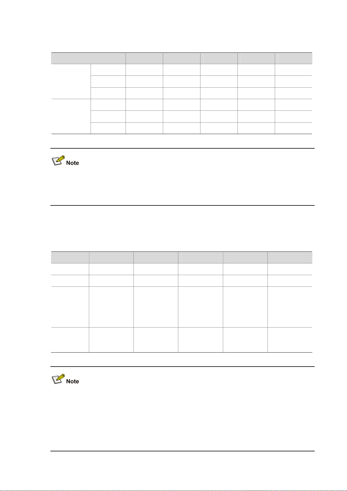
Table 1-3 Processor and memory of the MSR 30 series routers
Item MSR 30-11 MSR 30-16 MSR 30-20 MSR 30-40 MSR 30-60
Processor PowerPC PowerPC PowerPC PowerPC PowerPC
Boot ROM 2 MB 4 MB 4 MB 4 MB 4 MB
Memory DDR: 256 MB
CF CARD Not supported
DDR SDRAM:
256 MB
(default), 768
MB
(maximum)
256 MB
(default), 1 GB
(maximum)
DDR SDRAM:
256 MB
(default), 1 GB
(maximum)
256 MB
(default), 1 GB
(maximum)
DDR SDRAM:
256 MB
(default), 1 GB
(maximum)
256 MB
(default), 1 GB
(maximum)
DDR SDRAM:
256 MB
(default), 1 GB
(maximum)
256 MB
(default), 1 GB
(maximum)
z Boot ROM stores bootstrap.
z The memory is used to store the communication data between the system and the CPU when the
system is running.
z The CF card is used to store the software system and configuration file. The CF card LED blinks
when the system is reading/writing data from/to the CF card. In this case, do not remove the CF
card, otherwise hardware and software damage may occur.
1-2
Other Hardware Specifications
Table 1-4 Hardware specifications for the MSR 30 series routers
Item MSR 30-11 MSR 30-16 MSR 30-20 MSR 30-40 MSR 30-60
Dimensions (H
× W × D),
excluding feet
and mounting
ears
Weight 4.3 kg (9.5 lb) 6 kg (13.2 lb)
AC input
DC input Not supported Not supported
PoE input Not supported
Operating
temperature
44.2 × 442 ×
360 mm (1.74
× 17.4 × 14.17
in.)
Rated voltage
range: 100
VAC to 240
VAC, 50 Hz or
60 Hz
0°C to 40°C
(32°F to
104°F)
44.2 × 442 ×
441.8 mm
(1.74 × 17.4 ×
17.39 in.)
Rated voltage
range: 100
VAC to 240
VAC, 50 Hz or
60 Hz
Rated voltage
range: 100
VAC to 240
VAC, 50 Hz or
60 Hz
0°C to 40°C
(32°F to
104°F)
44.2 × 442 ×
441.8 mm
(1.74 × 17.4 ×
17.39 in.)
6.9 kg (15.2
lb)
Rated voltage
range: 100
VAC to 240
VAC, 50 Hz or
60 Hz
Rated voltage
range: –48
VDC to –60
VDC
Rated voltage
range: 100
VAC to 240
VAC, 50 Hz or
60 Hz
0°C to 40°C
(32°F to
104°F)
88.2 × 442 ×
422.3 mm
(3.47 × 17.4 ×
16.62 in.)
11.9 kg (26.2
lb)
Rated voltage
range: 100
VAC to 240
VAC, 50 Hz or
60 Hz
Rated voltage
range: –48
VDC to –60
VDC
Rated voltage
range: 100
VAC to 240
VAC, 50 Hz or
60 Hz
0°C to 40°C
(32°F to
104°F)
132 × 442 ×
421.8 mm
(5.20 × 174 ×
16.61 in.)
13.6 kg (30 lb)
Rated voltage
range: 100
VAC to 240
VAC, 50 Hz or
60 Hz
Rated voltage
range: –48
VDC to –60
VDC
Rated voltage
range: 100
VAC to 240
VAC, 50 Hz or
60 Hz
0°C to 40°C
(32°F to
104°F)
Relative
humidity
(noncondensi
ng)
MSR 30-11 Router
Appearance
1) Front view
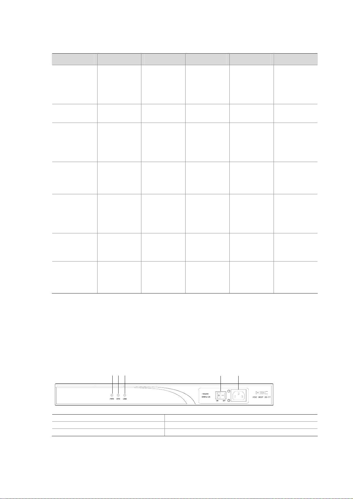
Figure 1-1 Front panel of the MSR 30-11
(1) Power LED (PWR) (2) System LED (SYS)
(3) ESM LED (4) Power switch
(5) Power receptacle
5% to 90% 5% to 90% 5% to 90% 5% to 90% 5% to 90%
(1)(2)(3)
(4)
(5)
2) Rear panel
1-3
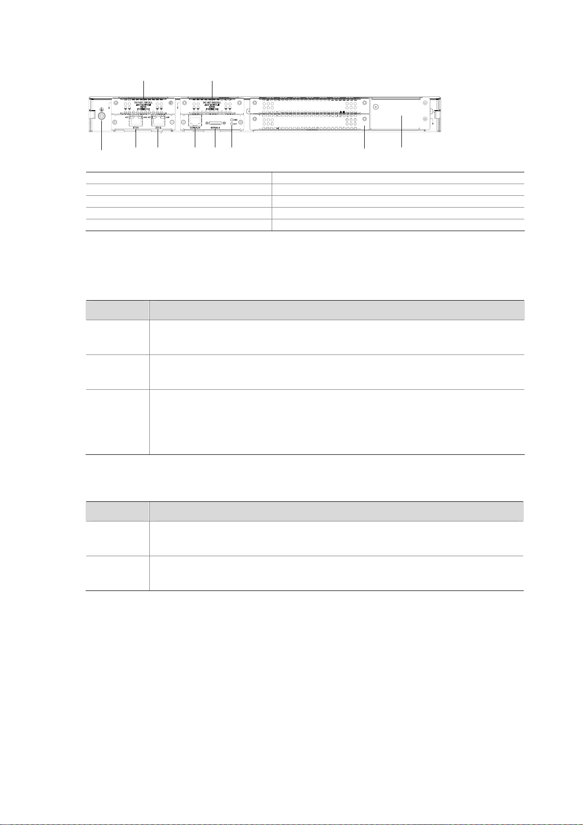
Figure 1-2 Rear panel of the MSR 30-11
(9)(10)
(2) (3)(1) (4) (5) (6) (8)(7)
(1) Grounding terminal (2) FE interface 1
(3) FE interface 0 (4) Console/AUX interface
(5) Serial interface (6) Serial interface status LEDs
(7) MIM/XMIM slot (8) Removable slide rails
(9) SIC slot 1 (10) SIC slot 2
Panel LEDs
Table 1-5 LEDs on the front panel of the MSR 30-11
LED Description
PWR
SYS
ON: The power supply of the system works normally.
OFF: The power supply of the system is disconnected.
Blinking: The system runs normally.
ON or OFF: The system runs abnormally.
OFF: No ESM is in position.
ESM
Solid green: An ESM is in position and works normally.
Blinking green: The ESM is processing data.
Solid yellow: An ESM is in position but is faulty.
Table 1-6 LEDs on the rear panel of the MSR 30-11
LED Description
LINK
ACT
MSR 30-16 Router
Appearance
1) Front view
OFF: No link is present.
ON: A link is present.
OFF: No data is being received or sent.
Blinking: Data is being received or sent.
1-4
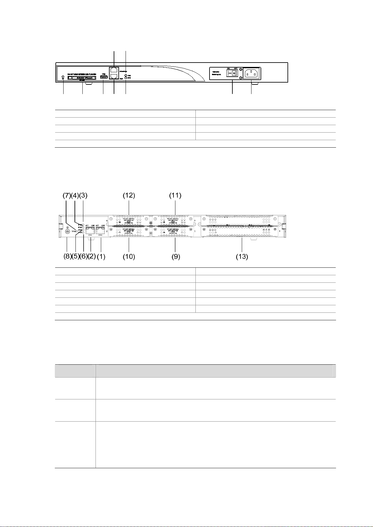
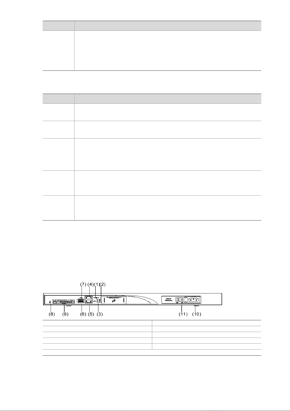
Figure 1-3 Front view of MSR 30-16
(1)
(3)
(2)
(4)(5)(6)(7) (8)(9)
(1) Power LED (POWER) (2) System LED (SYSTEM)
(3) Console port (CONSOLE) (4) Auxiliary port (AUX)
(5) USB interface (6) CF card
(7) CF card LED (8) Power socket
(9) Power switch
2) Rear view
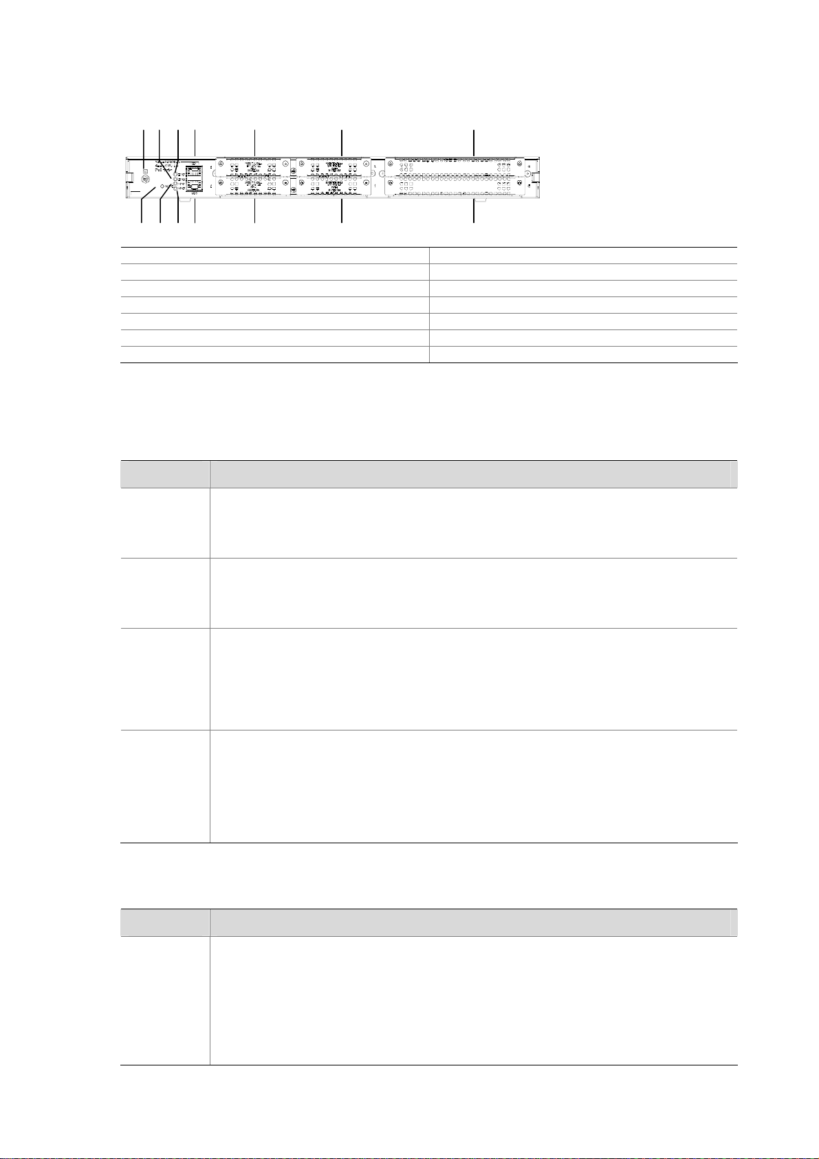
Figure 1-4 Rear view of MSR 30-16
(1) FE interface 0 (2) FE interface 1
(3) ESM1 LED (4) ESM0 LED
(5) VPM1 LED (6) VPM0 LED
(7) VCPM LED (8) Grounding terminal
(9) SIC slot 1 (10) SIC slot 2
(11) SIC slot 3 (12) SIC slot 4
(13) MIM slot 5
Panel LEDs
Table 1-7 Front panel LEDs description of MSR 30-16 router
LED Description
PWR
SYS
ON means: the system provides power for cards normally.
OFF means the system does not supply power for cards.
Blinking means the system is operating normally.
Steady ON or steady OFF means the system does not operate normally.
OFF means the USB interface has not been connected to a host.
Steady green means the USB interface is connected to a host and the host can be
USB0
removed.
Blinking green means data is being transferred to/from the host and the host cannot
be removed now.
1-5
LED Description
CF card LED:
Steady green means the CF card is in place and can be identified by the router.
CF
Table 1-8 Rear panel LEDs of MSR 30-16 Router
LED Description
Blinking green means the CF card is being accessed and must not be removed.
Steady yellow means the CF card is in place but cannot be identified by the router.
OFF means no CF card is inserted or the CF card cannot be identified.
LINK
ACT
ESM0 to 1
VCPM
VPM0 to 1
MSR 30-20 Router
OFF means no link is present.
ON means a link connection is established.
OFF means no data is being received or sent.
ON means data is being received or sent.
OFF means no ESM is in the ESM slot.
Solid green means an ESM is in the ESM slot and operates normally.
Blinking green means the ESM is processing data.
Solid yellow means an ESM is in the ESM slot but does not operate normally.
OFF means VCPM is not in the slot.
Steady green means a VCPM is in the slot and operates normally.
Steady yellow means a VCPM is in the slot but does not operate normally.
OFF means no VPM is in the VPMx slot.
Steady green means a VPM is in the VPMx slot and operates normally.
Steady yellow means a VPM is in the VPMx slot but does not operate normally.
Appearance
1) Front view
Figure 1-5 Front view of MSR 30-20
(1) Power LED (PWR) (2) System LED (SYS)
(3) USB LED (4) Console port (CONSOLE)
(5) Auxiliary port (AUX) (6) USB interface 0
(7) USB interface 1 (8) CF card LED
(9) CF card (10) Power socket
(11) Power switch
1-6
2) Rear view
Figure 1-6 Rear view of MSR 30-20
(13)(14)(9)
(12)(11)(10)
(2) (6)
(1)
(4) (3)
(5)
(8)
(7)
(1) GE interface 0 (2) GE interface 1
(3) SIC slot 1 (4) SIC slot 2
(5) SIC slot 3 (6) SIC slot 4
(7) MIM slot 5 (8) MIM slot 6
(9) Grounding terminal (10) VCPM LED
(11) VPM1 LED (12) VPM0 LED
(13) ESM0 LED (14) ESM1 LED
Panel LEDs
Table 1-9 Front panel LEDs description of MSR 30-20 router
LED Description
Power LED:
PWR
ON means the system provides power for cards normally.
OFF means the system does not supply power for cards.
Hardware system operation LED:
SYS
Blinking means the system is operating normally.
Steady ON or steady OFF means the system does not operate normally.
OFF means the USB interface has not been connected to a host.
Steady green means the USB interface is connected to a host and the host can be
USB0
removed.
Blinking green means data is being transferred to/from the host and the host cannot
be removed now.
CF card LED:
Steady green means the CF card is in the slot and can be identified by the router.
CF
Blinking green means the CF card is being accessed and cannot be removed.
Steady yellow means the CF card is in the slot but cannot be identified by the router.
OFF means no CF card is inserted or the CF card cannot be identified.
Table 1-10 Rear panel LEDs of MSR 30-20 Router
LED Description
OFF means no link is present.
Steady green means a 1000 Mbps connection has been established.
Blinking green means data is being received or transm itted at a speed of 1000 Mbps.
GE LED
Steady yellow means a 10/100 Mbps connection has been established.
Blinking yellow means data is being received and transmitted at a speed of 10/100
Mbps.
1-7

LED Description
ESM0 to 1
VCPM
VPM0 to 1
MSR 30-40 Router
Appearance
1) Front view
OFF means no ESM is in the ESM slot.
Steady green means an ESM is in the ESM slot and operates normally.
Blinking green means the ESM is processing data.
Steady yellow means an ESM is in the ESM slot but does not operate normally.
OFF means no VCPM is in the slot.
Steady green means a VCPM is in the slot and operates normally.
Steady yellow means a VCPM is in the slot but does not operate normally.
OFF means no VPM is in the VPMx slot.
Steady green means a VPM is in the VPM slot and operates normally.
Steady yellow means a VPM is in the VPM slot but does not operate normally.
Figure 1-7 Front view of MSR 30-40
(8)
(9)
(7) (4) (1)
(2)(3)
(6) (5)
(11)
(10)
(1) Power LED (PWR) (2) System LED (SYS)
(3) USB LED (4) Console port (CONSOLE)
(5) Auxiliary port (AUX) (6) USB interface 0
(7) USB interface 1 (8) CF card LED
(9) CF card (10) Power socket
(11) Power switch
2) Rear view
1-8
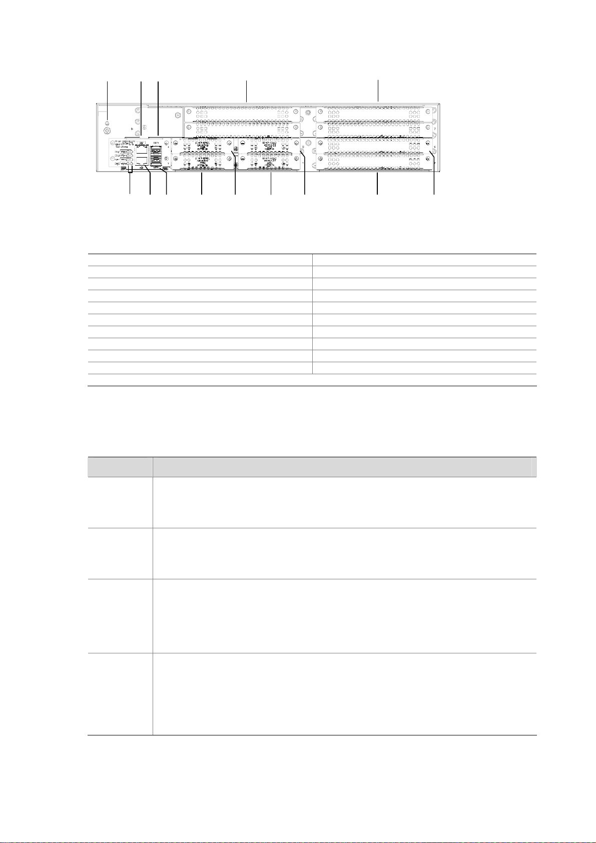
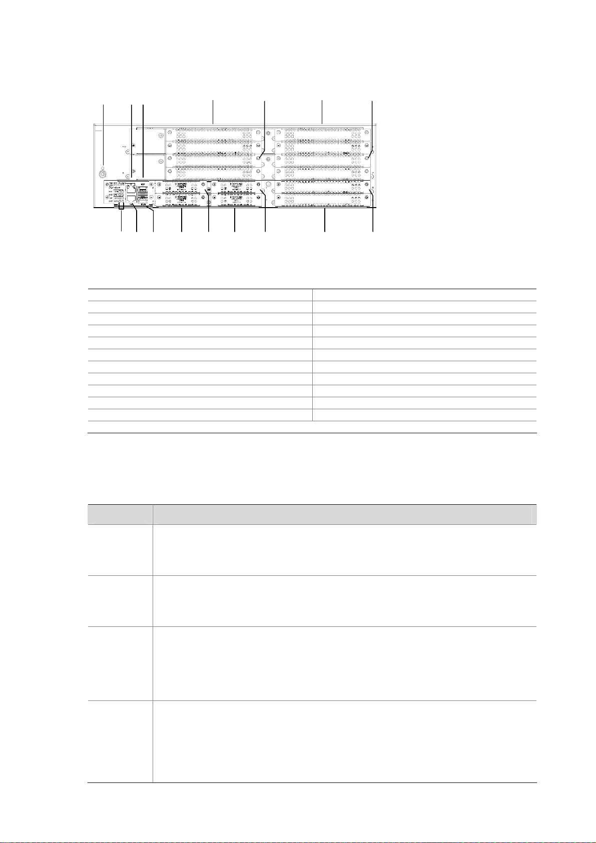
Figure 1-8 Rear view of MSR 30-40
(10)(12)
(4) (8)
(3) (7)
(2) (6)
(1) (5)
(9)
(11)
(20)(21)
(14) (13)(16) (17)(15) ( 18)
(19)
(1) VCPM LED (2) VCPM0 LED
(3) VPM1 LED (4) VPM2 LE D
(5) SFP0 LED (6) SFP1 LED
(7) ESM0 LED (8) ESM1 LE D
(9) GE0 port (10) GE1 port
(11) SFP0 port (12) SFP1 port
(13) SIC slot 1 (14) SIC slot 2
(15) SIC slot 3 (16) SIC slot 4
(17) MIM slot 5 (18) MIM slot 6
(19) MIM slot (20) MIM slot 8
(21) Grounding terminal
Panel LEDs
Table 1-11 Front panel LEDs description of MSR 30-40 router
LED Description
Power LED:
PWR
ON means the system provides power for cards normally.
OFF means the system does not supply power for cards.
Hardware system operation LED
SYS
Blinking means the system is operating normally.
Steady ON or steady OFF means the system does not operate normally.
OFF means the USB interface is not connected to a host;
Steady green means the USB interface has been connected to a host and the host
USB0
can be removed.
Blinking green means data is being transferred to/from the host and the host cannot
be removed now.
CF card LED
Steady green means the CF card is in the slot and can be identified by the router.
CF
Blinking green means the CF card is being accessed and cannot be removed.
Steady yellow means the CF card is in the slot but cannot be identified by the router.
OFF means no CF card is inserted or the CF card cannot be identified.
1-9
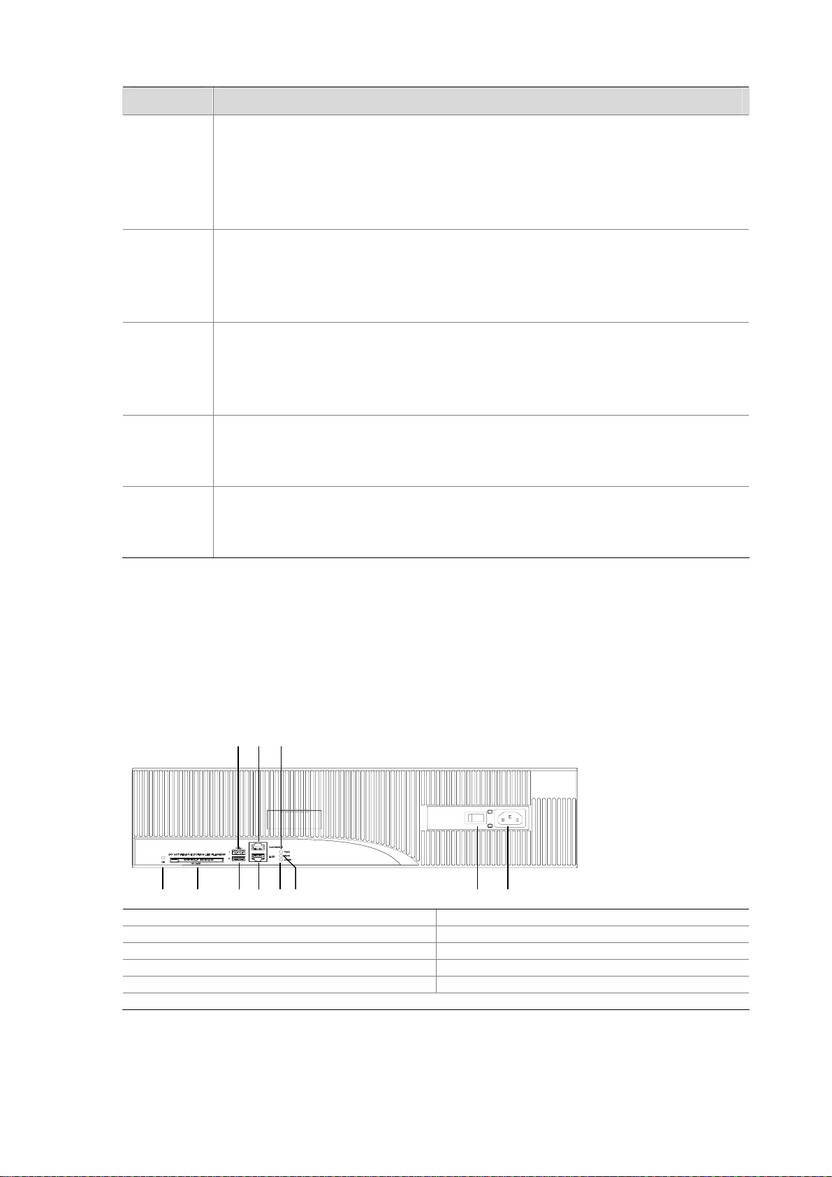
Table 1-12 Rear panel LEDs of MSR 30-40 Router
LED Description
OFF means no link is present.
Steady green means a 1000 Mbps connection has been established.
GE LED
Blinking green means data is being received or transm itted at a speed of 1000 Mbps.
Steady yellow means a 10/100 Mbps connection has been established.
Blinking yellow means data is being transmitted at a speed of 10/100 Mbps.
OFF means no SFP connection is established.
Steady green means SFP connection has been established.
SFP0 to 1
Blinking green means SFP is receiving or transmitting data.
Steady yellow means SFP cannot be identified by the router.
OFF means no ESM is in the ESM slot.
Steady green means an ESM is in the ESM slot and operates normally.
ESM0 to 1
Blinking green means the ESM is processing data.
Solid yellow means an ESM is in the ESM slot but does not operate normally.
OFF means no VCPM is in the slot.
VCPM
Steady green means a VCPM is in the slot and operates normally.
Steady yellow means a VCPM is in the slot but does not operate normally.
VPM0 to 2
MSR 30-60 Router
Appearance
1) Front view
Figure 1-9 Front view of MSR 30-60
(1) Power LED (PWR) (2) System LED (SYS)
(3) USB LED (4) Console port (CON)
(5) Auxiliary port (AUX) (6) USB interface 0
(7) USB interface 1 (8) CF card LED
(9) CF card (10) Power socket
(11) Power switch
OFF means no VPM is in the VPMx slot.
Steady green means a VPM is in the VPMx slot and operates normally.
Steady yellow means a VPM is in the VPMx slot but does not operate normally.
(7)
(1)(4)
(3)(2)
(5)(6)
(10)(8) (9) (11)
1-10
2) Rear view
Figure 1-10 Rear view of MSR 30-60
(23)
(10)(12)
(3 ) (7)
(2 ) (6)
(1 ) (5)
(22)
(9)(4 ) (8)
(11)
(14) (17)(15) (18)
(16)
(20)
(13)
(21)
(19)
(1) VCPM LED (2) VPM0 LED
(3) VPM1 LED (4) VPM LED
(5) SFP0 LED (6) SFP1 LED
(7) ESM0 LED (8) ESM1 LE D
(9) GE0 port (10) GE1 port
(11) SFP0 port (12) SFP1 port
(13) SIC slot 1 (14) SIC slot 2
(15) SIC slot 3 (16) SIC slot 4
(17) MIM slot 5 (18) MIM slot 6
(19) MIM slot 7 (20) MIM slot 8
(21) MIM slot 9 (22) MIM slot 10
(23) Grounding terminal
Panel LEDs
Table 1-13 Front panel LEDs description of MSR 30-60 router
LED Description
Power LED:
PWR
ON means the system provides power for cards normally.
OFF means the system does not supply power for cards.
Hardware system operation LED:
SYS
Blinking means the system is operating normally.
Steady ON or steady OFF means the system does not operate normally.
OFF means the USB interface has not been connected to a host.
Steady green means the USB interface has been connected to a host and the host
USB0
can be removed.
Blinking green means data is being transferred to/from the host and the host cannot
be removed now.
CF card LED:
Steady green means the CF card is in the slot and can be identified by the router.
CF
Blinking green means the CF card is being accessed and cannot be removed.
Steady yellow means the CF card is in the slot but cannot be identified by the router.
OFF means no CF card is inserted or the CF card cannot be identified.
1-11

Table 1-14 Rear panel LEDs of MSR 30-60 Router
LED Description
OFF means no link is present.
Steady green means a 1000 Mbps connection has been established.
Blinking green means data is being received or transm itted at a speed of 1000 Mbps.
GE LED
SFP0 to 1
ESM0 to 1
Steady yellow means a 10/100 Mbps connection has been established.
Blinking yellow means data is being transmitted and received at a speed of 10/100
Mbps.
OFF means no SFP connection is established.
Steady green means SFP connection has been established.
Blinking green means SFP is receiving or transmitting data.
Steady yellow means SFP cannot be identified by the router.
OFF means no ESM is in the ESM slot.
Steady green means an ESM is in the ESM slot and operates normally.
Blinking green means the ESM is processing data.
Solid yellow means an ESM is in the ESM slot but does not operate normally.
OFF means no VCPM is in the slot.
VCPM
VPM0 to 2
Steady green means a VCPM is in the slot and operates normally.
Steady yellow means a VCPM is in the slot but does not operate normally.
OFF means no VPM is in the VPMx slot.
Steady green means a VPM is in the VPMx slot and operates normally.
Steady yellow means a VPM is in the VPMx slot but does not operate normally.
Generic Modules
The MSR 30 Series Routers support generic modules SIC and MIM. For details about the interface
cards, refer to MSR Series Routers Interface Card and Interface Module Manual.
SIC/DSIC Cards
MSR 30 series routers adopt modular design and sup port a wide range of option al SIC/DSIC cards that
provide various interfaces, such as synchronous/asynchronous serial interface, Ethernet interface,
E1/T1, ISDN BRI/PRI, ADSL, audio interface, and Layer 2 switching interface.
SIC cards mainly differ from DSIC cards in that a SIC card occupies one o rdinary SIC slot while a DSIC
card occupies two (horizontal) SIC slots. You need to remove the slide rails from the router before
installing a DSIC card.
A PoE-capable interface card can supply power remotely only when it is installed in a PoE router. If it is
installed in a non-PoE router, it serves as an ordinary switching module only.
For the MSR 30-16, SIC/DSIC cards are subject to the following limitations:
1-12

z SIC-4FSW/1FEA/1GEC/1ADSL/1ADSL-I can be installed only in slot 2 or slot 4.
z SIC-2BS/2BU/2BSV can be installed only in slot 1 or slot 3.
For the MSR 30-20/40/60, SIC/DSIC cards are subject to the following limitations:
z SIC-4FSW/1FEA/1GEC/1ADSL/1ADSL-I can be installed only in slot 2 or slot 4.
MIM/DMIM Cards
MSR 30 series routers adopt modular design and support a wide range of optional MIM/DMIM cards
that provide various interfaces, such as synchronous/asynchronous serial interf ace, Ethernet interface,
E1/T1 interface, ISDN BRI/PRI interface, ADSL interface, audio interface, and Layer 2 switching
interface.
MIM cards, DMIM cards, mainly differ in the following aspects:
A MIM card occupie s one ordinary MIM slot, a DMIM card occupies two ordinary (horizont al) MIM slots,
You need to remove the slide rails from the router before installing a DMIM card.
ESM
z High-performance network data encryption ESM module (ESM-ANDE)
z Standard network data encryption ESM module (ESM-SNDE)
ESM module supports IPSec and by using hardware encryption expedites IP packet encryption. The
use of hardware encryption/decryption and hashing operation allows the router to encrypt p a ckets with
high performance and reliability.
The encryption card is optional. On a router installed with an encryption card, the main control board
functions to route IP packets and implement encryption-enabled VPN, while the encryption card
functions to encrypt packets.
Table 1-15 Encryption card attributes
Protocol
Hardware encryption algorithm
VPM/VCPM
Voice processing module (VPM) functions to implement the encryption/decryption, EC and CNG of
voices.
Attribute Description
IP sec
Key algorithms: DES, 3DES, AES
Authentication algorithms: HMAC-MD5-96, HMAC-SHA-1-96
Voice co-processing module (VCPM) processes the voice data in combination with VPM.
z Voice co-processing module (RT-VCPM)
z 8-channel voice processing module (RT-VPM8)
z 16-channel voice processing module (RT-VPM16)
z 24-channel voice processing module (RT-VPM24)
z 32-channel voice processing module (RT-VPM32)
1-13

Table of Contents
2 Installation Preparations···························································································································2-1
Requirements on Environment ···············································································································2-1
Requirements on Temperature/Humidity ························································································2-1
Requirements on Cleanness···········································································································2-1
Requirements on Electrostatic Discharge Prevention·····································································2-2
Requirements on Electromagnetic Environments···········································································2-2
Requirements on Preventing Lightning···························································································2-2
Requirements on Workbench··········································································································2-3
Safety Precautions··································································································································2-3
Installation Tools, Meters and Equipments·····························································································2-3
i

2 Installation Preparations
Requirements on Environment
MSR 30 Series must be used indoors. To ensure the normal operation and prolong their service life, the
following requirements for inst allation site must be met.
Requirements on Temperature/Humidity
To ensure the normal operation and prolong their service life, certain requirement s on temp erature and
humidity in the equipment room shall be met. If the relative humidity is too high, the insulation m aterials
in it will deteriorate easily or even lead to electric leakage. Sometimes this will result in change to the
mechanical performance of the materials and rusting of the metal compon ents. If the relative humidity is
too low, the fastening screw will become loosen due to shrinkage of the isolation spacer. In an
environment with dry climate, static electricity may be produced, putting the CMOS of the route r to risk.
High temperature is of the greatest risk: for it will significantly degrade the router’s reliability, speed up
aging process of the insulating materials, and shorten the service life of the router.
The requirements on the temperature and humidity for MSR 30 Series are shown in the following table:
Table 2-1 Temperature/humidity requirements in the equipment room
Temperature Relative humidity
0°C to 40°C (32°F to 104°F)
Requirements on Cleanness
Dust is harmful to the safe operation of the Router. Dust on the chassis may result in static absorption,
thus causing poor contact of the metal connection compon ents or points. Espe cially under the condition
of low indoor humidity, dust is easier to be absorbed.
The requirements on the dust concentration and diameter of MSR 30 Series Routers are shown in the
following table:
Table 2-2 Limitation on dust content in equipment room
Diameter (μm) 0.5 1 3 5
Concentration
(particle/m³)
1.4 × 10
5% to 90% (noncondensing)
7
7 × 10
5
2.4 × 10
5
1.3 × 10
5
Besides the dust specifications, the equipment room of the Router should also meet the rigorous
requirements for the content of salt, acid and sulfide. These harmful gases could accelerate the metal
erosion and aging process of some part s. The specific limit s of these harmful g ases as SO
and CI2 are given in the following table.
NH
3
2-1
, H2S, NO2,
2

Table 2-3 Harmful limits in equipment room
Gas Max (mg/m3)
SO
H2S
NH
CI
2
3
2
0.2
0.006
0.05
0.01
Requirements on Electrostatic Discharge Prevention
Although many antistatic considerations have been given to MSR 30 Series Routers, damage to the
router’s circuit or even the whole equipment may still happen when the static electric ity exceeds the
tolerance threshold.
In the communication network to which the routers are connected, static induction mainly comes from
two aspects: external electric fields such as outdoor high voltage power line or thunder and internal
environment like flooring materials or the whole equipment structure. Thus, the following should be
considered to safeguard the equipment against the ESD:
z Make sure that the equipment and the floor are well grounded.
z The equipment room is dust-proof.
z Maintain an appropriate humidity and temperature.
z Wear an ESD-preventive wrist strap and uniform when contacting the circuit board.
z Place the uninstalled circuit board on the antistatic workbench, with its face upward, or put it into
the static shielding bag.
z When observing or removing the uninstalled circuit board, please touch the edge of the circuit
board, and avoid contacting the devices on it.
Requirements on Electromagnetic Environments
The interference sources, no matter where they come from, af fect the routers with cap acitance couplin g,
inductance coupling, radiation of electromagnetic wave, common impedance (including the grounding
system) or conducting line (power line, signal line and transmission line etc.). So the following should be
considered:
z Take effective measures to prevent the power system from being interfered with by the power grid
system.
z Use an earthing system or lightning protection grounding different from that for the power supply
equipment and keep them as far as possible.
z Keep the router far away from the radio launcher, radar launcher, and high-frequency devices
working in high current.
z Use electromagnetic shielding when necessary.
Requirements on Preventing Lightning
Although many measures have been taken to protect MSR 30 Series from lightning, if the lightning
intensity exceeds a certain range, damage to the router may still happen. To protect the router from
lightning better, the following should be considered:
z Ensure the PGND wire of the chassis is well grounded.
2-2
z Ensure the ground point of the socket of AC power supply is well grounded.
z To enhance the lightning protection capability of the power supply, a lightning arrester could be
installed at the input end of the power supply.
z As for the signal line outdoors to which the interface modules of MSR 30 series routers are
connected, such as ISDN line, telephone line, E1/T1 line, etc, a special lightning arrester should be
installed at the input end of the signal line to enhance the lightning protection capability.
Requirements on Workbench
When installing MSR 30 Series Routers, observe the following:
z There is spacing reserved at the air inlet and outlet in the router so as to facilitate the radiation of
the router cabinet.
z Make sure that the rack has a good ventilation system.
z Make sure that the rack is sturdy enough to support the weight of the device and the installation
accessories.
z Make sure that the rack is well-grounded.
Safety Precautions
When reading this manual, pay attention to the following:
It indicates that this operation is incorrect and may seriously damage the router or
endanger the operator . Please follow the correct operation procedures for sake of safety.
It indicates that during the installation and usage of the router, the operation needs
attention. If this operation is performed incorrectly, it might affect the operation of the router.
When installing or working on the router, you are recommended to:
z Keep the router far away from the heat sources and water/liquid.
z Make sure that the router has been correctly grounded.
z Wear an ESD-preventive wris t strap in installation and maintenance, making sure that the strap
has good skin contact.
z Do not hot swap the interface modules and interface cards of the router.
z Do not hot swap any cable.
z Correctly connect the interface cable for the router. Do not connect the telephone cable (including
the ISDN cable) to the AUX port or the console port.
z Use laser with caution. Do not directly stare into apertures or fiber-optic connectors that emit laser
radiation.
z Adopt uninterrupted power supply (UPS).
Installation Tools, Meters and Equipments
Tools
z Phillips screwdriver
z Straight screwdriver
z ESD-preventive twist strap
2-3

Cables
z PGND wire and power cord
z Console cable
z Optional cables
Meters and equipment
z Hub or LAN switch
z Console terminal (it could be a PC)
z Equipment related to the selected modules
z Multimeter
MSR 30 Series Routers are not shipped with any installation tools, meters, or devices.
2-4

Table of Contents
3 Installation··················································································································································3-1
Installation Process·································································································································3-1
Installing Cabinets···································································································································3-2
Installing the Router································································································································3-2
Installing the Router on a Workbench·····························································································3-2
Installing the Router in a Rack ········································································································3-2
Installing Generic Modules······················································································································3-3
Connecting the PGND·····························································································································3-4
Connecting the Power Cord····················································································································3-4
Power Input and PGND···················································································································3-5
Connecting the AC Power Cord······································································································3-5
Connecting the DC Power Cord······································································································3-5
Connecting the RPS Power Cord····································································································3-7
Connecting the Console Terminal···········································································································3-8
Fixed Interfaces·······································································································································3-9
Ethernet Interface····························································································································3-9
Connecting AUX to a Modem········································································································3-11
Interface Card Module···························································································································3-12
Slide Rail Installation on MSR 30-16/30-20 and Removal····································································3-12
Slide Rails······································································································································3-12
Installing the Slide ·························································································································3-13
Uninstalling the Slide Rail··············································································································3-13
Slide Rail Installation on MSR 30-40/30-60 and Removal····································································3-14
Slide Rails······································································································································3-14
Installing the Slide Rail··················································································································3-15
Uninstalling the Slide Rail··············································································································3-16
Verifying Installation······························································································································3-17
i
3 Installation
Installation Process
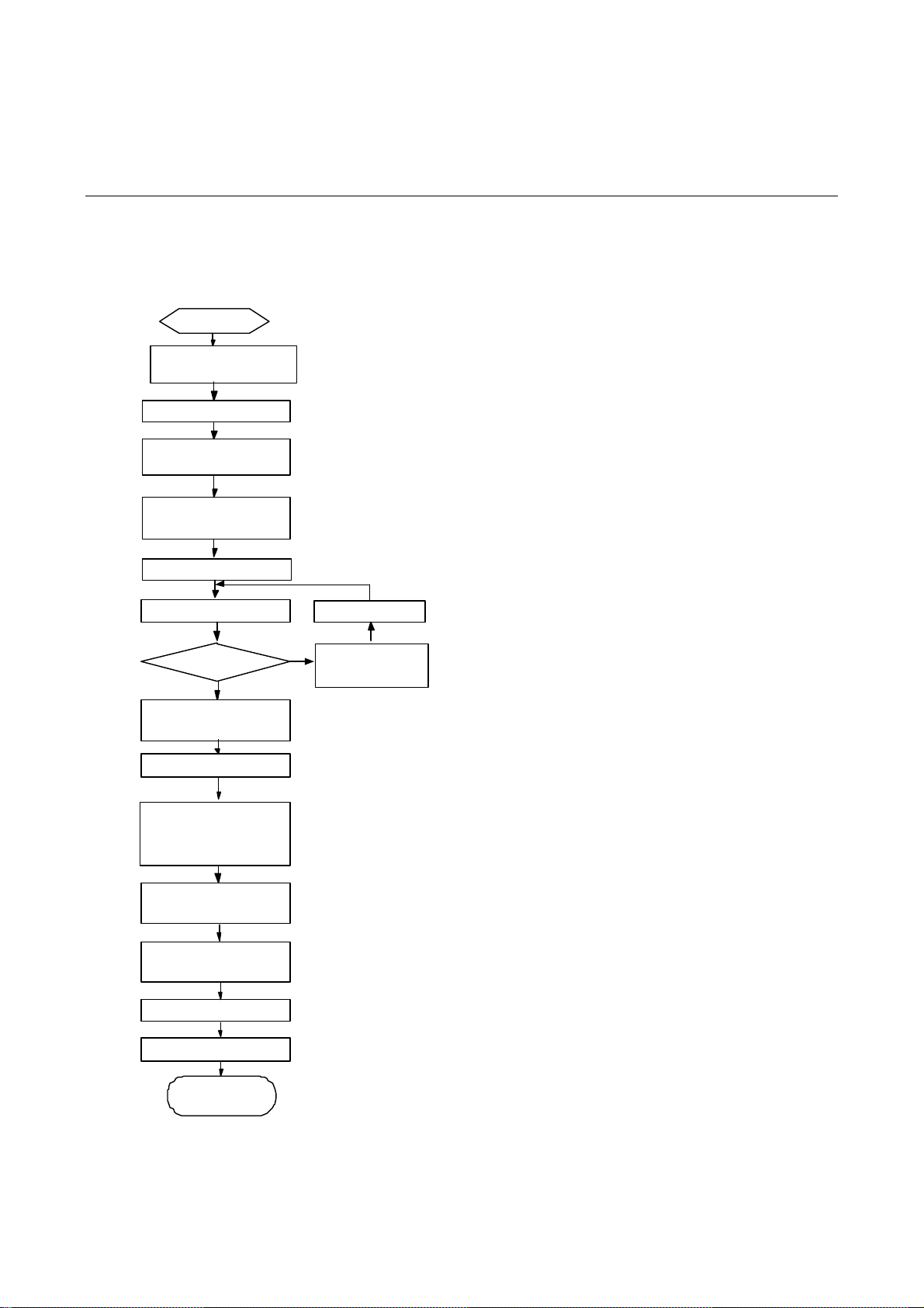
Figure 3-1 MSR 30 Series Routers installation process
Start
Mo u n t t h e r ack
Connect PGND
C onne ct the powe r
cord
Connec t to t he
console terminal
Verify install ati o n
Pow er on
Normal?
YES
T u r n off th e p o we r
sw itch
Install the FICs
Install multifunctional
interf ace mo du l e s
Connec t to t he
Ether net
NO
Tr o u bleshoot
Turn of f the
power switch
Connect t o the WA N
Verify i n stal lat i on
Pow er on
End
3-1
 Loading...