

Page 1

Hangzhou H3C Technologies Co., Ltd.
http://www.h3c.com
Document version: T2-08047L-20101217-C-1.05
H3C MSR 30 Routers
Installation Guide
Page 2

Copyright © 2006-2010, Hangzhou H3C Technologies Co., Ltd. and its licensors
All rights reserved
No part of this manual may be reproduced or transmitted in any form or by any means without prior
written consent of Hangzhou H3C Technologies Co., Ltd.
Trademarks
H3C,
SecPro, SecPoint, SecEngine, SecPath, Comware, Secware, Storware, NQA, VVG, V
XGbus, N-Bus, TiGem, InnoVision and HUASAN are trademarks of Hangzhou H3C Technologies Co.,
Ltd.
All other trademarks that may be mentioned in this manual are the property of their respective owners
Notice
The information in this document is subject to change without notice. Every effort has been made in the
preparation of this document to ensure accuracy of the contents, but all statements, information, and
recommendations in this document do not constitute the warranty of any kind, express or implied.
Environmental protection
This product has been designed to comply with the environmental protection requirements. The storage,
use, and disposal of this product must meet the applicable national laws and regulations.
, Aolynk, , H3Care,
, TOP G, , IRF, NetPilot, Neocean, NeoVTL,
2
G, VnG, PSPT,
Page 3
Preface
The H3C MSR 30 Routers Installation Guide describes how to install the H3C MSR 30 Routers, maintain
software and hardware of the router, and solve problems you may encounter during the installation
process.
This preface includes:
•
Audience
Conventions
•
About the H3C MSR documentation set
•
Obtaining documentation
•
Technical support
•
Documentation feedback
•
Audience
This documentation is intended for:
• Network planners
• Field technical support and servicing engineers
• Network administrators working with the MSR Series
Conventions
This section describes the conventions used in this documentation set.
Symbols
Convention Description
WARNING
CAUTION
IMPORTANT
NOTE
TIP
An alert that calls attention to important information that if not understood or followed can
result in personal injury.
An alert that calls attention to important information that if not understood or followed can
result in data loss, data corruption, or damage to hardware or software.
An alert that calls attention to essential information.
An alert that contains additional or supplementary information.
An alert that provides helpful information.
Page 4

Network topology icons
Represents a generic network device, such as a router, switch, or firewall.
Represents a routing-capable device, such as a router or Layer 3 switch.
Represents a generic switch, such as a Layer 2 or Layer 3 switch, or a router that supports
Layer 2 forwarding and other Layer 2 features.
About the H3C MSR documentation set
The H3C MSR documentation set includes:
Category Documents Purposes
MSR 900 Routers Marketing
brochures
MSR 20-1X Routers Marketing
brochures
Product description and
specifications
MSR 20-2X[40] Routers Marketing
brochures
MSR 30 Routers Marketing brochures
MSR 50-40[60] Routers Marketing
brochures
Describe product specifications and
benefits.
Hardware specifications
and installation
Software configuration
Operations and
maintenance
MSR 900 Routers Installation guide
MSR 20-1X Routers Installation guide
MSR 20-2X[40] Routers Installation
guide
MSR 30 Routers Installation guide
MSR 50 Routers Installation guide
MSR Series Routers Interface Module
Manual
MSR Series Routers Configuration
guides
MSR Series Routers Command
references
MSR Series Routers Web
Configuration guides
MSR Basic Series Routers Release
notes
MSR Standard Series Routers Release
notes
Provides a complete guide to hardware
installation and hardware
specifications.
Describe software features and
configuration procedures.
Provide a quick reference to all
available commands.
Describe Web software features and
configuration procedures.
Provide information about the product
release, including the version history,
hardware and software compatibility
matrix, version upgrade information,
technical support information, and
software upgrading.
Page 5

Obtaining documentation
You can access the most up-to-date H3C product documentation on the World Wide Web at
http://www.h3c.com.
Click the links on the top navigation bar to obtain different categories of product documentation:
[Technical Support & Documents > Technical Documents] – Provides hardware installation, software
upgrading, and software feature configuration and maintenance documentation.
[Products & Solutions] – Provides information about products and technologies, as well as solutions.
[Technical Support & Documents > Software Download] – Provides the documentation released with the
software version.
Technical support
customer_service@h3c.com
http://www.h3c.com
Documentation feedback
You can e-mail your comments about product documentation to info@h3c.com.
We appreciate your comments.
Page 6

Contents
Overview ······································································································································································ 1
Introduction ········································································································································································1
System Description ····························································································································································1
Fixed Interfaces·························································································································································1
MSR 30-10 Router····················································································································································3
MSR 30-11 Router····················································································································································5
MSR 30-11E Router··················································································································································6
MSR 30-11F Router··················································································································································7
MSR 30-16 Router····················································································································································8
MSR 30-20 Router················································································································································· 10
MSR 30-40 Router················································································································································· 12
MSR 30-60 Router················································································································································· 15
Generic Modules···························································································································································· 17
SIC/DSIC Cards···················································································································································· 17
MIM/DMIM Cards················································································································································ 18
ESM········································································································································································· 18
VPM/VCPM ··························································································································································· 18
Installation Preparations ············································································································································19
Requirements on Environment ······································································································································· 19
Requirements on Temperature/Humidity ············································································································ 19
Requirements on Cleanness·································································································································· 19
Requirements on Electrostatic Discharge Prevention·························································································· 20
Requirements on Electromagnetic Environments ································································································20
Requirements on Preventing Lightning················································································································· 20
Requirements on Workbench······························································································································· 21
Safety Precautions·························································································································································· 21
Installation Tools, Meters and Equipments ··················································································································21
Installation···································································································································································23
Installation Process ·························································································································································23
Installing the Cabinet ····················································································································································· 23
Installing the Router························································································································································ 23
Installing the Router on a Workbench················································································································· 24
Installing the Router in a Cabinet ························································································································ 24
Installing Generic Modules ··········································································································································· 27
Connecting the PGND··················································································································································· 27
Connecting the Power Cord·········································································································································· 27
Power Input and PGND········································································································································ 28
Connecting the AC Power Cord ·························································································································· 28
Connecting the DC Power Cord ·························································································································· 28
Connecting the RPS Power Cord ························································································································· 29
Connecting the Console Terminal ································································································································ 31
Fixed Interfaces ······························································································································································32
Ethernet Interface··················································································································································· 32
Connecting AUX to a Modem······························································································································ 34
Interface Cards and Interface Modules ······················································································································· 35
Installing and Removing Interface Modules················································································································· 35
Slide Rail ································································································································································ 35
Installing a DSIC/DMIM Interface Card ············································································································· 37
i
Page 7

Removing a DSIC/DMIM Interface Card ··········································································································· 38
Installing an XMIM Interface Card ······················································································································ 38
Removing an XMIM Interface Card····················································································································· 38
Verifying Installation ······················································································································································ 39
Startup and Configuration·········································································································································40
Startup ············································································································································································· 40
Setting up Configuration Environment ················································································································ 40
Powering on the Router········································································································································· 42
Startup Process······················································································································································· 43
Configuration Fundamentals ········································································································································· 44
Basic Configuration Procedures··························································································································· 44
Command Line Interface······································································································································· 44
Arranging Slots and Numbering Interfaces········································································································ 45
Software Maintenance···············································································································································48
Introduction ····································································································································································· 48
Files········································································································································································· 48
Software Maintenance Methods·························································································································· 49
Maintaining Application Program and Configuration Through Command Lines···················································· 50
Maintaining the Router Through TFTP Server ····································································································· 51
Maintaining the Router Through FTP Server ······································································································· 53
BootWare Menu····························································································································································· 56
Main BootWare Menu·········································································································································· 56
BootWare Submenus ············································································································································ 58
Upgrading an Application Program Through an Ethernet Interface········································································· 60
Configuring Ethernet Interface Parameters ········································································································· 61
Upgrading Procedure ···········································································································································62
Upgrading BootWare Through Ethernet Interface······································································································ 64
Upgrading BootWare Through Serial Interface·········································································································· 64
XModem Protocol Overview ································································································································ 64
Modifying Serial Interface Parameters················································································································ 65
Upgrading BootWare··········································································································································· 66
Upgrading an Application Program Through a Serial Interface··············································································· 68
Maintaining Application and Configuration Files ······································································································ 68
Dealing with Password Loss·········································································································································· 70
User Password Loss ··············································································································································· 70
BootWare Password Loss ····································································································································· 71
Super Password Loss············································································································································· 71
Backing Up and Restoring BootWare·························································································································· 72
Hardware Maintenance ············································································································································73
Preparing Tools ······························································································································································ 73
Opening/Closing the Chassis Cover··························································································································· 73
Internal Structure of the Router······································································································································ 75
Removing/Installing a Power Module·························································································································· 77
Installing and Removing the Power Module ······································································································· 78
Installing/Removing a CF Card···································································································································· 79
Structure·································································································································································· 80
Installing CF Card ················································································································································· 80
Removing CF Card················································································································································ 80
Replacing a Memory Module ······································································································································· 81
Memory Module Structure···································································································································· 83
Memory Module Slot············································································································································· 83
Installing/Removing a Memory Module ············································································································· 83
Replacing a VPM ···························································································································································85
ii
Page 8

VPM Structure ························································································································································ 85
VPM Slot································································································································································· 86
Installing/Removing a VPM·································································································································· 86
Installing/Removing an ESM/VCPM Card ················································································································· 86
Troubleshooting··························································································································································88
Troubleshooting the Power System······························································································································· 88
Troubleshooting the Configuration System·················································································································· 88
Troubleshooting Application Image Upgrade············································································································· 89
Index ···········································································································································································91
iii
Page 9

Overview
Introduction
MSR 30 Routers were self-developed by our company for use on enterprise-level networks. Depending on
the network size, MSR 30 Routers can be either core routers on small and medium enterprise networks,
or access routers for network branches on some large-sized enterprise networks. Therefore, MSR 30
Routers are suitable for the application on the carrier-level networks, such as telecom management
networks and billing networks. MSR 30 Routers adopt modular design and support a wide range of
optional smart interface cards (SICs) and multi-function interface modules (MIMs). The MSR 30-16 can
adopt AC and PoE, and the MSR 30-20, 30-40 and 30-60 can adopt AC, DC, and PoE.
Except the MSR 30-11 and the AC-powered MSR 30-16, the MSR 30 routers each provide a redundancy
power system (RPS) interface to enhance the routers’ reliability. The PoE-powered routers can remotely
supply power to its powered devices (PDs).
MSR 30 include these models:
• MSR 30-10
• MSR 30-11
• MSR 30-11E
• MSR 30-11F
• MSR 30-16
• MSR 30-20
• MSR 30-40
• MSR 30-60
System Description
Fixed Interfaces
Table 1 Fixed interfaces of the MSR 30 routers
Item
Fixed
interfaces
Console 1 1 1 1 1 1
AUX
USB
FE
MSR
30-10
1 1 1 1 1 1
1 0 1 1 1 2
2 2 2 2 2 0
MSR
30-11
MSR
30-11E
MSR
30-11F
MSR
30-16
MSR
30-20
MSR
30-40
1
1
2
0
MSR
30-60
1
1
2
0
GE
Two
electric
0 0 0 0 0
1
al
interfac
es
Two
Combo
interfac
es
Two
Combo
interfac
es
Page 10

Item
MSR
30-10
SAE 0 1 0 0 0 0 0 0
FE
switching
ports
0 0 24 48 0 0 0 0
MSR
30-11
MSR
30-11E
MSR
30-11F
MSR
30-16
MSR
30-20
MSR
30-40
MSR
30-60
4
(compa
SIC 2 2 2 2
External
cards
MIM
ESM 1 1 1 1 2 2 2 2
Internal
cards
Processor
Boot ROM 2 MB 2 MB 2 MB 2 MB 4 MB 4 MB 4 MB 4 MB
Memory
VCPM 0 0 0 0 1 1 1 1
VPM 1 0 0 0 2 2 3 3
1
(compa
tible
with 1
XMIM)
PowerPC PowerPC PowerPC PowerPC PowerPC PowerPC PowerPC PowerP
DDR II:
256
MB
1
(comp
atible
with 1
XMIM)
DDR:
256
MB
1 1 1 2
DDR II:
256 MB
DDR II:
256 MB
tible
with 2
DSICs)
DDR
SDRAM
: 256
MB
(default
), 768
MB
(maxim
um)
4
(compa
tible
with 2
DSICs)
DDR SDRAM: 256 MB
(default), 1 GB (maximum)
4
(compa
tible
with 2
DSICs)
4
(compa
tible
with 1
DMIM)
4
(compa
tible
with 2
DSICs)
6
(compa
tible
with 2
DMIMs)
C
Flash memory
CF card Not supported 256 MB (default), 1 GB (maximum)
Dimensions (H × W ×
D), excluding feet and
mounting ears
Weight
AC input Rated voltage range: 100 VAC to 240 VAC, 50 Hz or 60 Hz
256
MB
44.2 ×
442 ×
360
mm
(1.74 ×
17.4 ×
14.17
in.)
4.8 kg
(10.58
lb)
32 MB 256 MB 256 MB
44.2 ×
442 ×
360
mm
(1.74 ×
17.4 ×
14.17
in.)
4.6 kg
(10.14
lb)
44.2 ×
442 ×
360
mm
(1.74 ×
17.4 ×
14.17
in.)
4.5 kg
(9.92
lb)
2
44.2 ×
442 ×
360 mm
(1.74 ×
17.4 ×
14.17
in.)
4.8 kg
(10.58
lb)
Not
support
ed
44.2 ×
442 ×
441.8
mm
(1.74 ×
17.4 ×
17.39
in.)
6 kg
(13.2
lb)
Not
support
ed
44.2 ×
442 ×
441.8
mm
(1.74 ×
17.4 ×
17.39
in.)
6.9 kg
(15.2
lb)
Not
support
ed
88.2 ×
442 ×
422.3
mm
(3.47 ×
17.4 ×
16.62
in.)
11.9
kg
(26.2
lb)
Not
support
ed
132 ×
442 ×
421.8
mm
(5.20 ×
174 ×
16.61
in.)
13.6
kg (30
lb)
Page 11
Item
MSR
30-10
MSR
30-11
MSR
30-11E
MSR
30-11F
MSR
30-16
MSR
30-20
MSR
30-40
MSR
30-60
Rated
voltage
range:
DC input
PoE input Not supported
Maximum power 54 W 54 W 54 W 54 W 100 W 125 W 210 W 210 W
Operating temperature 0°C to 40°C (32°F to 104°F)
Relative humidity
(non-condensing)
–48
VDC to
–60
VDC
5% to 90%
Not
support
ed
Not
support
ed
Not
supporte
d
Not
support
ed
Rated voltage range: 100 VAC to 240
VAC, 50 Hz or 60 Hz
Rated
voltage
range:
–48
VDC to
–60
VDC
Rated
voltage
range:
–48
VDC to
–60
VDC
NOTE:
• The console port and AUX port of the MSR 30-10/30-11/30-11E/30-11F share the same physical port.
• Boot ROM stores the Bootstrap for booting the router.
• The memory is used to store the communication data between the system and the CPU when the system
is running.
• The CF card is used to store the software system and configuration file. The CF card LED blinks when the
system is reading/writing data from/to the CF card. In this case, do not remove the CF card, otherwise
hardware and software damage may occur.
Rated
voltage
range:
–48
VDC to
–60
VDC
• Do not unplug the USB device during USB data transmission; otherwise, data loss or even hardware
failures may occur.
• The USB interface does not support hot-swapping of USB modems from Sierra Wireless.
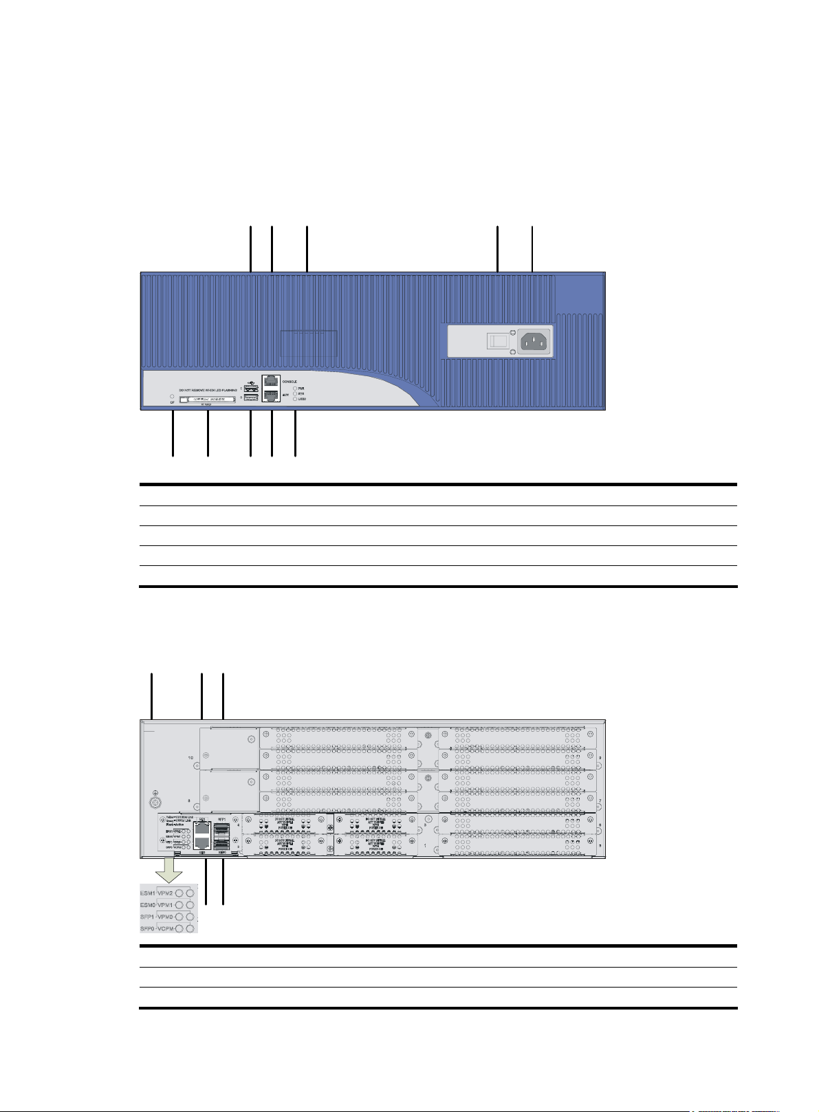
MSR 30-10 Router
Appearance
1. Front view
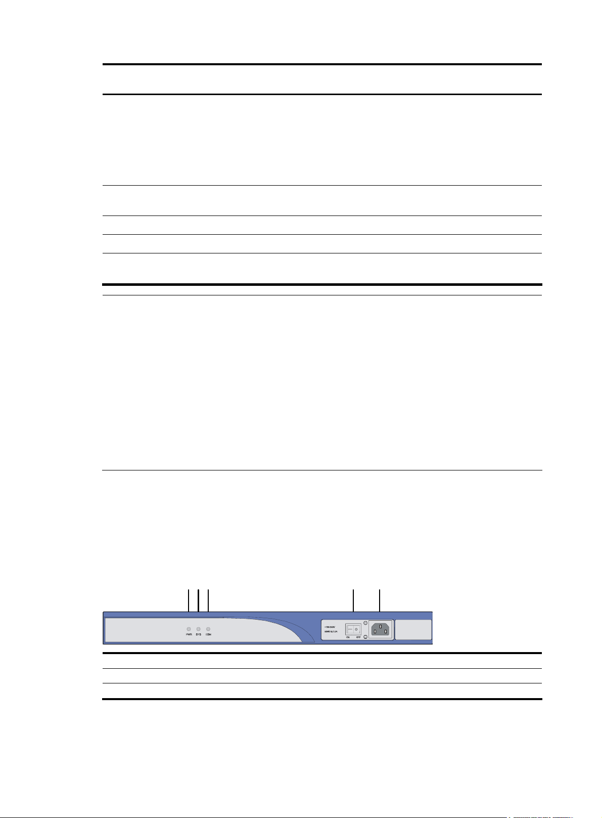
Figure 1 Front panel of an MSR 30-10
(1)
(1) Power LED (PWR) (2) System LED (SYS)
(3) ESM LED (4) Power switch
(5) Power receptacle
(3)(2)
(5)(4)
3
Page 12
2.
Figure 2 Rear panel of an MSR 30-10
Panel LEDs
Table 2 LEDs on the front panel of an MSR 30-10
Rear view
(1) SIC slot 2 (2) SIC slot 1
(3) MIM/XMIM slot (4) Removable slide rails
(5) USB interface (6) Console/AUX interface
(7) ETH 0 interface LEDs (8) ETH 0 interface
(9) ETH 1 interface LEDs (10) ETH 1 interface
(11) Grounding terminal
LED Description
PWR
SYS
• ON: The power supply of the system works normally.
• OFF: The power supply of the system is disconnected.
• Blinking: The system runs normally.
• ON or OFF: The system runs abnormally.
• OFF: No ESM is in position.
ESM
• Solid green: An ESM is in position and works normally.
• Blinking green: The ESM is processing data.
• Solid yellow: An ESM is in position but is faulty.
Table 3 ETH LEDs on the rear panel of an MSR 30-10
LED Description
LINK
ACT
• OFF: No link is present.
• ON: A link is present.
• OFF: No data is being received or sent.
• Blinking: Data is being received or sent.
4
Page 13
MSR 30-11 Router
Appearance
1. Front view
Figure 3 Front panel of an MSR 30-11
(1) Power LED (PWR) (2) System LED (SYS) (3) ESM LED
(4) Power switch (5) Power receptacle
2. Rear view
Figure 4 Rear panel of an MSR 30-11
Panel LEDs
Table 4 LEDs on the front panel of an MSR 30-11
(1) Grounding terminal (2) FE interface 1
(3) FE interface 0 (4) Console/AUX interface
(5) Serial interface (6) Serial interface status LEDs
(7) MIM/XMIM slot (8) Removable slide rails
(9) SIC slot 1 (10) SIC slot 2
LED Description
PWR
SYS
• ON: The power supply of the system works normally.
• OFF: The power supply of the system is disconnected.
• Blinking: The system runs normally.
• ON or OFF: The system runs abnormally.
• OFF: No ESM is in position.
ESM
• Solid green: An ESM is in position and works normally.
• Blinking green: The ESM is processing data.
• Solid yellow: An ESM is in position but is faulty.
5
Page 14
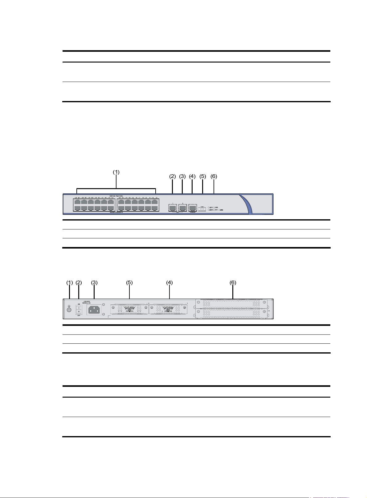
Table 5 LEDs on the rear panel of an MSR 30-11
LED Description
LINK
ACT
• OFF: No link is present.
• ON: A link is present.
• OFF: No data is being received or sent.
• Blinking: Data is being received or sent.
MSR 30-11E Router
Appearance
1. Front view
Figure 5 Front view of an MSR 30-11E
2. Rear view
Figure 6 Rear view of an MSR 30-11E
Panel LEDs
Table 6 Front panel LEDs of an MSR 30-11E router
(1) 24 FE switching interfaces (2) ETH interface 1
(3) ETH interface 0 (4) Console/AUX interface
(5) USB interface (6) LEDs
(1) Grounding terminal (2) Power switch
(3) Power receptacle (4) SIC slot 1
(5) SIC slot 2 (6) MIM/XMIM slot
LED Description
PWR
SYS
• ON means: the system provides power for cards normally.
• OFF means the system does not supply power for cards.
• Blinking means the system is operating normally.
• Steady ON or steady OFF means the system does not operate normally.
6
Page 15
LED Description
• OFF means no ESM is in the ESM slot.
ESM
• Solid green means an ESM is in the ESM slot and operates normally.
• Blinking green means the ESM is processing data.
• Solid yellow means an ESM is in the ESM slot but does not operate normally.
ETH0
ETH1
• OFF means no link is present.
• ON means a link connection is established.
• OFF means no link is present.
• ON means a link connection is established.
MSR 30-11F Router
Appearance
1. Front view
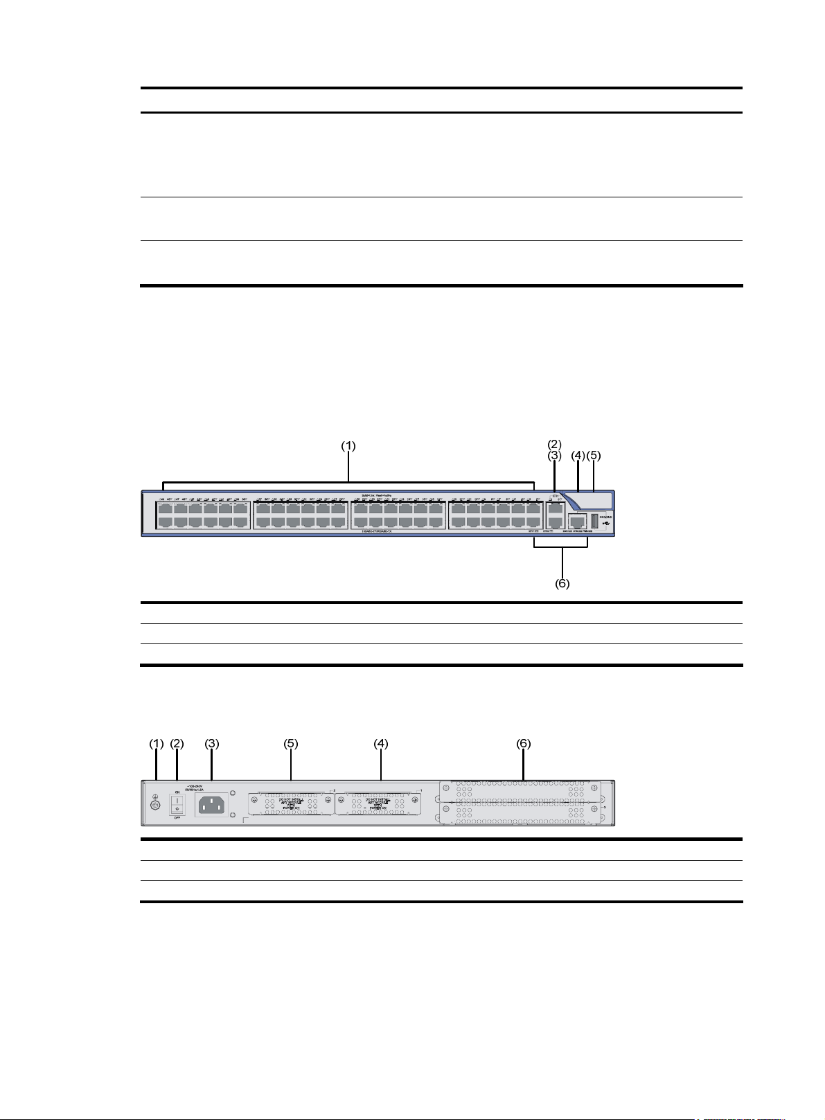
Figure 7 Front view of an MSR 30-11F
(1) 48 FE switching interfaces (2) ETH interface 1
(3) ETH interface 0 (4) Console/AUX interface
(5) USB interface (6) LEDs
2. Rear view
Figure 8 Rear view of an MSR 30-11F
(1) Grounding terminal (2) Power switch
(3) Power receptacle (4) SIC slot 1
(5) SIC slot 2 (6) MIM/XMIM slot
7
Page 16
Panel LEDs
Table 7 Front panel LEDs of an MSR 30-11F router
LED Description
PWR
SYS
• ON means: the system provides power for cards normally.
• OFF means the system does not supply power for cards.
• Blinking means the system is operating normally.
• Steady ON or steady OFF means the system does not operate normally.
• OFF means no ESM is in the ESM slot.
ESM
• Solid green means an ESM is in the ESM slot and operates normally.
• Blinking green means the ESM is processing data.
• Solid yellow means an ESM is in the ESM slot but does not operate normally.
ETH0
ETH1
• OFF means no link is present.
• ON means a link connection is established.
• OFF means no link is present.
• ON means a link connection is established.
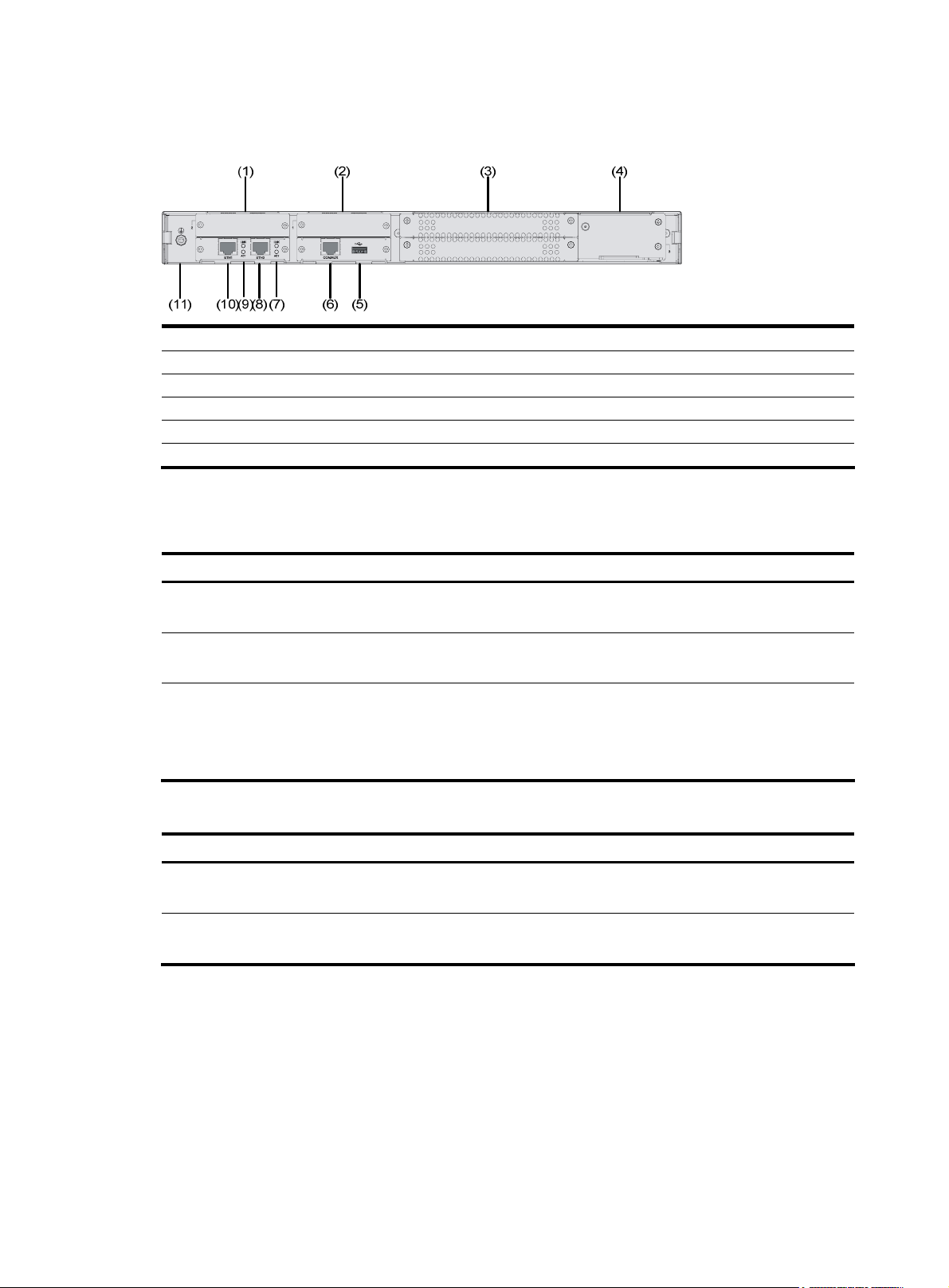
MSR 30-16 Router
Appearance
1. Front view
Figure 9 Front view of an MSR 30-16
(1) Power LED (POWER) (2) System LED (SYSTEM)
(3) Console port (CONSOLE) (4) Auxiliary port (AUX)
(5) USB interface (6) CF card
(7) CF card LED (8) Power socket
(9) Power switch
8
Page 17
2.
Figure 10 Rear view of an MSR 30-16
Panel LEDs
Table 8 Front panel LEDs of an MSR 30-16 router
Rear view
(1) FE interface 0 (2) FE interface 1
(3) Grounding terminal (4) LEDs
(5) SIC slot 1 (6) SIC slot 2
(7) SIC slot 3 (8) SIC slot 4
(9) MIM slot 5
LED Description
PWR
SYS
• ON means: the system provides power for cards normally.
• OFF means the system does not supply power for cards.
• Blinking means the system is operating normally.
• Steady ON or steady OFF means the system does not operate normally.
• OFF means the USB interface has not been connected to a host.
USB0
• Steady green means the USB interface is connected to a host and the host can be removed.
• Blinking green means data is being transferred to/from the host and the host cannot be
removed now.
CF card LED:
• Steady green means the CF card is in place and can be identified by the router.
CF
• Blinking green means the CF card is being accessed and must not be removed.
• Steady yellow means the CF card is in place but cannot be identified by the router.
• OFF means no CF card is inserted or the CF card cannot be identified.
Table 9 Rear panel LEDs of an MSR 30-16 router
LED Description
LINK
ACT
• OFF means no link is present.
• ON means a link connection is established.
• OFF means no data is being received or sent.
• ON means data is being received or sent.
9
Page 18
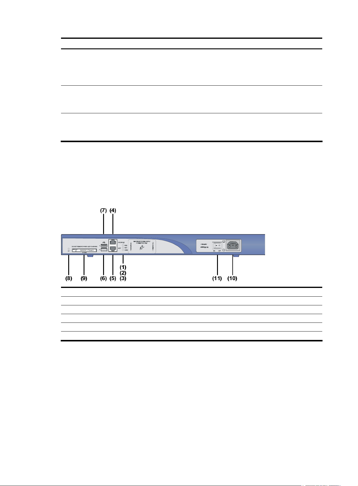
LED Description
• OFF means no ESM is in the ESM slot.
ESM0 to 1
• Solid green means an ESM is in the ESM slot and operates normally.
• Blinking green means the ESM is processing data.
• Solid yellow means an ESM is in the ESM slot but does not operate normally.
• OFF means VCPM is not in the slot.
VCPM
• Steady green means a VCPM is in the slot and operates normally.
• Steady yellow means a VCPM is in the slot but does not operate normally.
• OFF means no VPM is in the VPMx slot.
VPM0 to 1
• Steady green means a VPM is in the VPMx slot and operates normally.
• Steady yellow means a VPM is in the VPMx slot but does not operate normally.
MSR 30-20 Router
Appearance
1. Front view
Figure 11 Front view of an MSR 30-20
(1) Power LED (PWR) (2) System LED (SYS)
(3) USB LED (4) Console port (CONSOLE)
(5) Auxiliary port (AUX) (6) USB interface 0
(7) USB interface 1 (8) CF card LED
(9) CF card (10) Power socket
(11) Power switch
10
Page 19
2.
Figure 12 Rear view of an MSR 30-20
Panel LEDs
Table 10 Front panel LEDs of an MSR 30-20 router
Rear view
(1) GE interface 0 (2) GE interface 1
(3) LEDs (4) Grounding terminal
(5) SIC slot 1 (6) SIC slot 2
(7) SIC slot 3 (8) SIC slot 4
(9) MIM slot 5 (10) MIM slot 6
LED Description
Power LED:
PWR
• ON means the system provides power for cards normally.
• OFF means the system does not supply power for cards.
Hardware system operation LED:
SYS
• Blinking means the system is operating normally.
• Steady ON or steady OFF means the system does not operate normally.
• OFF means the USB interface has not been connected to a host.
USB0
• Steady green means the USB interface is connected to a host and the host can be removed.
• Blinking green means data is being transferred to/from the host and the host cannot be
removed now.
CF card LED:
• Steady green means the CF card is in the slot and can be identified by the router.
CF
• Blinking green means the CF card is being accessed and cannot be removed.
• Steady yellow means the CF card is in the slot but cannot be identified by the router.
• OFF means no CF card is inserted or the CF card cannot be identified.
Table 11 Rear panel LEDs of an MSR 30-20 router
LED Description
• OFF means no link is present.
• Steady green means a 1000 Mbps connection has been established.
GE LED
• Blinking green means data is being received or transmitted at a speed of 1000 Mbps.
• Steady yellow means a 10/100 Mbps connection has been established.
• Blinking yellow means data is being received and transmitted at a speed of 10/100 Mbps.
11
Page 20
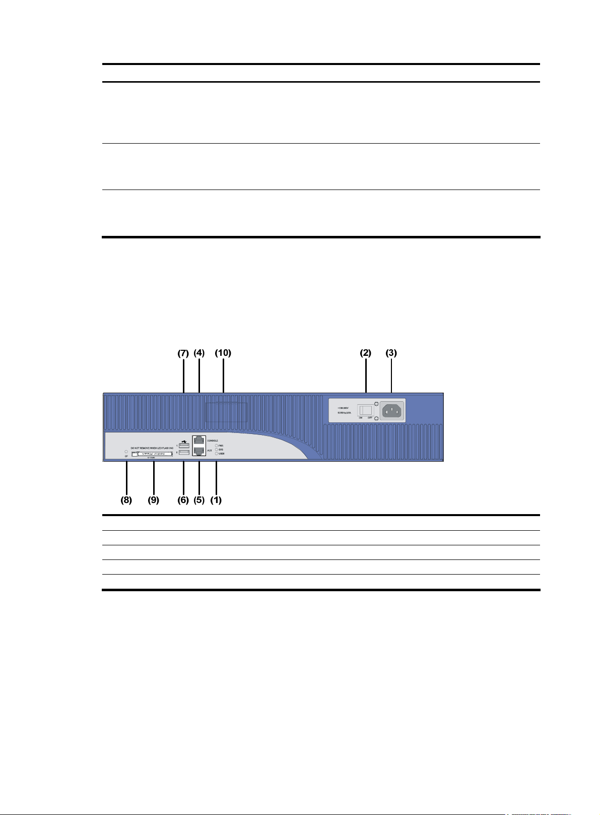
LED Description
• OFF means no ESM is in the ESM slot.
ESM0 to 1
• Steady green means an ESM is in the ESM slot and operates normally.
• Blinking green means the ESM is processing data.
• Steady yellow means an ESM is in the ESM slot but does not operate normally.
• OFF means no VCPM is in the slot.
VCPM
• Steady green means a VCPM is in the slot and operates normally.
• Steady yellow means a VCPM is in the slot but does not operate normally.
• OFF means no VPM is in the VPMx slot.
VPM0 to 1
• Steady green means a VPM is in the VPM slot and operates normally.
• Steady yellow means a VPM is in the VPM slot but does not operate normally.
MSR 30-40 Router
Appearance
1. Front view
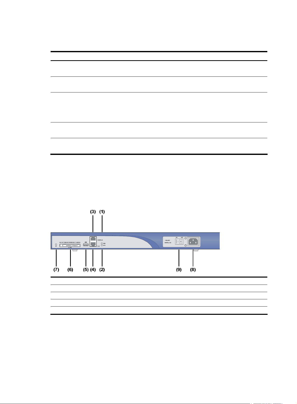
Figure 13 Front view of an MSR 30-40
(1) LEDs (2) Power switch
(3) Power socket (4) Console port (CONSOLE)
(5) Auxiliary port (AUX) (6) USB interface 0
(7) USB interface 1 (8) CF card LED
(9) CF card (10) RPS filler panel
12
Page 21
2.
Rear view
Figure 14 Rear view of an MSR 30-40
(1) GE interface 0 (2) GE interface 1
(3) SFP0 port (4) SFP1 port
(5) LEDs (6) Grounding terminal
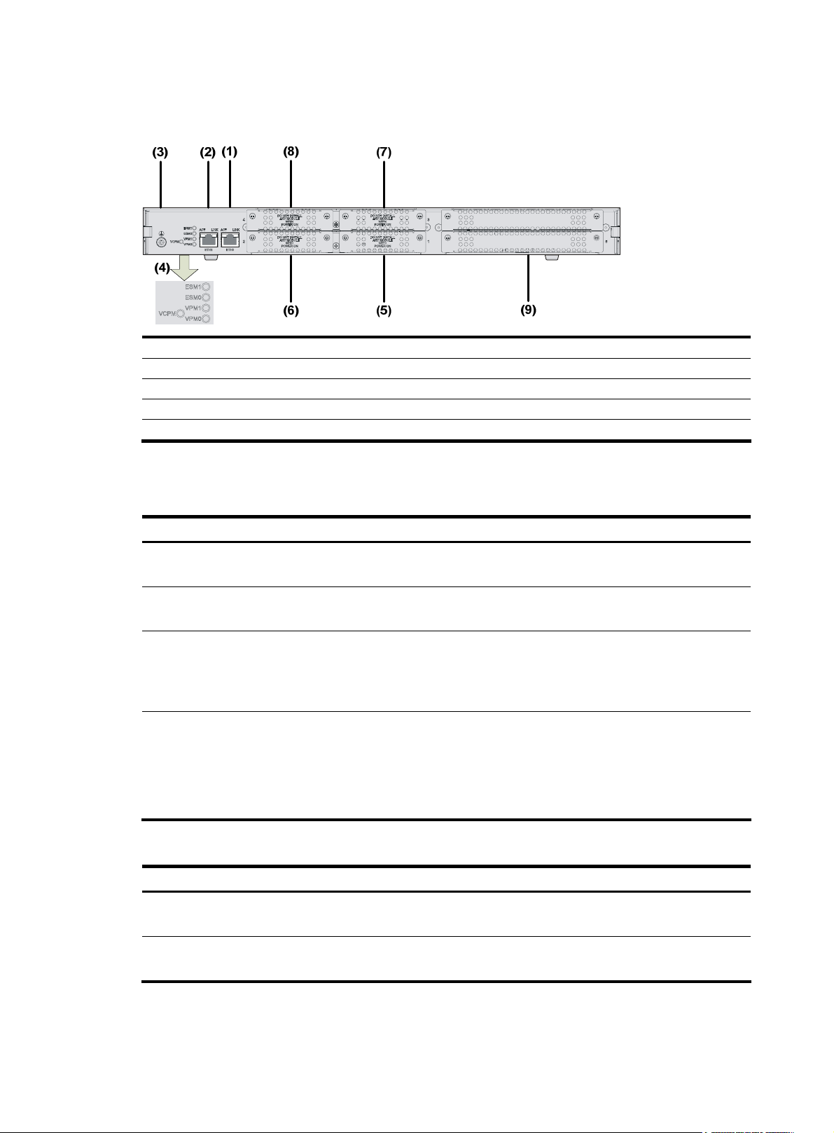
Slot arrangement
As a self-developed 2U device, each MSR 30-40 router provides four SIC slots and four MIM slots
respectively, delivering expansion of access and service capabilities. In addition, the SIC slide rail
between Slot 1 and Slot 2 can be removed so that two SIC slots can be extended to form a DSIC slot.
Similarly, Slot 3 and Slot 4 can be arranged to form another DSIC slot, and Slot 7 and Slot 8 can be
arranged to serve as a DMIM slot.
Figure 15 Slots on an MSR 30-40 router
Panel LEDs
Table 12 Front panel LEDs of an MSR 30-40 router
LED Description
Power LED:
PWR
• ON means the system provides power for cards normally.
• OFF means the system does not supply power for cards.
Hardware system operation LED
SYS
• Blinking means the system is operating normally.
• Steady ON or steady OFF means the system does not operate normally.
13
Page 22

LED Description
• OFF means the USB interface is not connected to a host;
• Steady green means the USB interface has been connected to a host and the host can be
USB0
removed.
• Blinking green means data is being transferred to/from the host and the host cannot be
removed now.
CF card LED
• Steady green means the CF card is in the slot and can be identified by the router.
CF
• Blinking green means the CF card is being accessed and cannot be removed.
• Steady yellow means the CF card is in the slot but cannot be identified by the router.
• OFF means no CF card is inserted or the CF card cannot be identified.
Table 13 Rear panel LEDs of an MSR 30-40 router
LED Description
• OFF means no link is present.
• Steady green means a 1000 Mbps connection has been established.
GE LED
• Blinking green means data is being received or transmitted at a speed of 1000 Mbps.
• Steady yellow means a 10/100 Mbps connection has been established.
• Blinking yellow means data is being transmitted at a speed of 10/100 Mbps.
• OFF means no SFP connection is established.
SFP0 to 1
• Steady green means SFP connection has been established.
• Blinking green means SFP is receiving or transmitting data.
• Steady yellow means SFP cannot be identified by the router.
• OFF means no ESM is in the ESM slot.
ESM0 to 1
• Steady green means an ESM is in the ESM slot and operates normally.
• Blinking green means the ESM is processing data.
• Solid yellow means an ESM is in the ESM slot but does not operate normally.
• OFF means no VCPM is in the slot.
VCPM
• Steady green means a VCPM is in the slot and operates normally.
• Steady yellow means a VCPM is in the slot but does not operate normally.
• OFF means no VPM is in the VPMx slot.
VPM0 to 2
• Steady green means a VPM is in the VPMx slot and operates normally.
• Steady yellow means a VPM is in the VPMx slot but does not operate normally.
14
Page 23
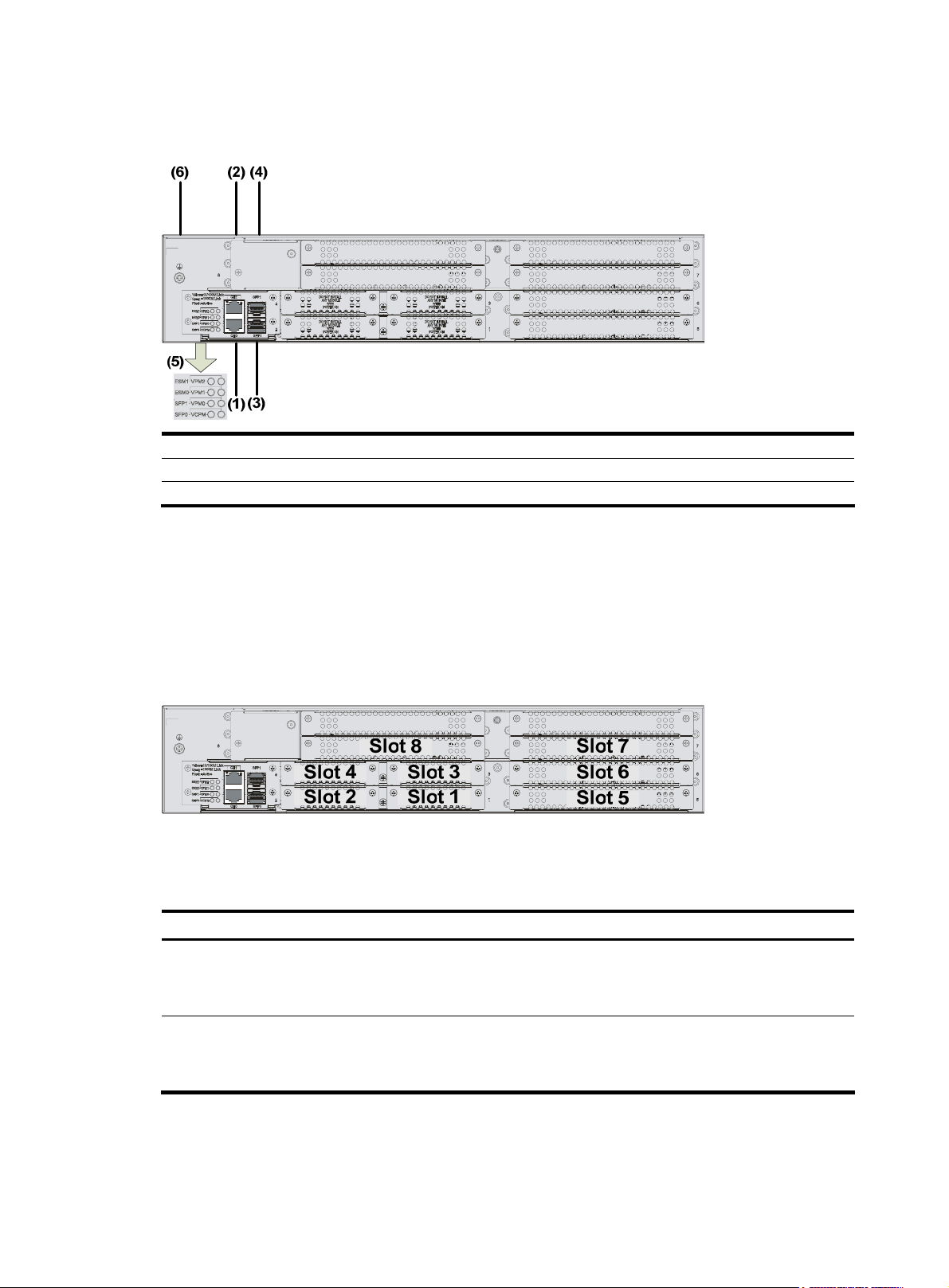
MSR 30-60 Router
Appearance
1. Front view
Figure 16 Front view of an MSR 30-60
(1) LEDs (2) Power switch
(3) Power socket (4) Console port (CON)
(5) Auxiliary port (AUX) (6) USB interface 0
(7) USB interface 1 (8) CF card LED
(9) CF card (10) RPS filler panel
2. Rear view
(10) (2) (3)(4)(7)
(1)(5)(6)(9)(8)
Figure 17 Rear view of an MSR 30-60
(6) (2) (4)
(5)
(1)(3)
(1) GE interface 0 (2) GE interface 1
(3) SFP interface 0 (4) SFP interface 1
(5) LEDs (6) Grounding terminal
15
Page 24
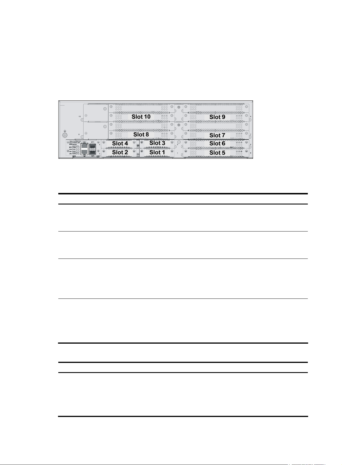
Slot arrangement
As a self-developed 3U device, each MSR 30-60 router provides four SIC slots and six MIM slots
respectively, delivering expansion of access and service capabilities. In addition, the SIC slide rail
between Slot 1 and Slot 2 can be removed so that two SIC slots can be extended to form a DSIC slot.
Similarly, Slot 3 and Slot 4 can be extended to form another DSIC slot, Slot 7 and Slot 8 can be arranged
to serve as a DMIM slot, and Slot 9 and Slot 10 together serve as another DMIM slot.
Figure 18 Slots on an MSR 30-60 router
Panel LEDs
Table 14 Front panel LEDs of an MSR 30-60 router
LED Description
Power LED:
PWR
• ON means the system provides power for cards normally.
• OFF means the system does not supply power for cards.
Hardware system operation LED:
SYS
• Blinking means the system is operating normally.
• Steady ON or steady OFF means the system does not operate normally.
• OFF means the USB interface has not been connected to a host.
• Steady green means the USB interface has been connected to a host and the host can be
USB0
removed.
• Blinking green means data is being transferred to/from the host and the host cannot be
removed now.
CF card LED:
• Steady green means the CF card is in the slot and can be identified by the router.
CF
• Blinking green means the CF card is being accessed and cannot be removed.
• Steady yellow means the CF card is in the slot but cannot be identified by the router.
• OFF means no CF card is inserted or the CF card cannot be identified.
Table 15 Rear panel LEDs of an MSR 30-60 router
LED Description
• OFF means no link is present.
• Steady green means a 1000 Mbps connection has been established.
GE LED
• Blinking green means data is being received or transmitted at a speed of 1000 Mbps.
• Steady yellow means a 10/100 Mbps connection has been established.
• Blinking yellow means data is being transmitted and received at a speed of 10/100 Mbps.
16
Page 25

LED Description
• OFF means no SFP connection is established.
SFP0 to 1
• Steady green means SFP connection has been established.
• Blinking green means SFP is receiving or transmitting data.
• Steady yellow means SFP cannot be identified by the router.
• OFF means no ESM is in the ESM slot.
ESM0 to 1
• Steady green means an ESM is in the ESM slot and operates normally.
• Blinking green means the ESM is processing data.
• Solid yellow means an ESM is in the ESM slot but does not operate normally.
• OFF means no VCPM is in the slot.
VCPM
• Steady green means a VCPM is in the slot and operates normally.
• Steady yellow means a VCPM is in the slot but does not operate normally.
• OFF means no VPM is in the VPMx slot.
VPM0 to 2
• Steady green means a VPM is in the VPMx slot and operates normally.
• Steady yellow means a VPM is in the VPMx slot but does not operate normally.
Generic Modules
The MSR 30 Routers support generic modules SIC and MIM. For details about the interface cards, refer
to MSR Series Routers Interface Module Manual.
For the types of interface modules that each model of the MSR 30 routers can accommodate, refer to
Appendix A Interface Card and Interface Module Purchase Guide in the MSR Series Routers Interface
Module Manual.
SIC/DSIC Cards
MSR 30 routers adopt modular design and support a wide range of optional SIC/DSIC cards that
provide various interfaces, such as synchronous/asynchronous serial interface, Ethernet interface, E1/T1,
ISDN BRI/PRI, ADSL, audio interface, and Layer 2 switching interface.
SIC cards mainly differ from DSIC cards in that a SIC card occupies one ordinary SIC slot while a DSIC
card occupies two (horizontal) SIC slots. You need to remove the slide rails from the router before
installing a DSIC card.
NOTE:
A PoE-capable interface card can supply power remotely only when it is installed in a PoE router. If it is
installed in a non-PoE router, it serves as an ordinary switching module only.
For the MSR 30-16, SIC/DSIC cards are subject to the following limitations:
• SIC-4FSW/1FEA/1GEC/1ADSL/1ADSL-I can be installed only in slot 2 or slot 4.
• SIC-2BS/2BU/2BSV can be installed only in slot 1 or slot 3.
For the MSR 30-20/40/60, SIC/DSIC cards are subject to the following limitations:
• SIC-4FSW/1FEA/1GEC/1ADSL/1ADSL-I can be installed only in slot 2 or slot 4.
17
Page 26

MIM/DMIM Cards
MSR 30 routers adopt modular design and support a wide range of optional MIM/DMIM cards that
provide various interfaces, such as synchronous/asynchronous serial interface, Ethernet interface, E1/T1
interface, ISDN BRI/PRI interface, ADSL interface, audio interface, and Layer 2 switching interface.
MIM cards, DMIM cards, mainly differ in the following aspects:
A MIM card occupies one ordinary MIM slot, while a DMIM card occupies two ordinary (horizontal)
MIM slots. You need to remove the slide rails from the router before installing a DMIM card.
ESM
• High-performance network data encryption ESM module (ESM-ANDE)
• Standard network data encryption ESM module (ESM-SNDE)
ESM module supports IPSec and by using hardware encryption expedites IP packet encryption. The use
of hardware encryption/decryption and hashing operation allows the router to encrypt packets with high
performance and reliability.
The encryption card is optional. On a router installed with an encryption card, the main control board
functions to route IP packets and implement encryption-enabled VPN, while the encryption card functions
to encrypt packets.
Table 16 Encryption card attributes
Attribute Description
Protocol
Hardware encryption algorithm
VPM/VCPM
Voice processing module (VPM) functions to implement the encryption/decryption, EC and CNG of
voices.
Voice co-processing module (VCPM) processes the voice data in combination with VPM.
• Voice co-processing module (RT-VCPM)
• 8-channel voice processing module (RT-VPM8)
• 16-channel voice processing module (RT-VPM16)
• 24-channel voice processing module (RT-VPM24)
• 32-channel voice processing module (RT-VPM32)
IP sec
Key algorithms: DES, 3DES, AES
Authentication algorithms: HMAC-MD5-96, HMAC-SHA-1-96
18
Page 27

Installation Preparations
Requirements on Environment
The MSR 30 routers are designed for indoor applications. To ensure the normal operation and prolong
their service life, the following requirements for installation site must be met.
Requirements on Temperature/Humidity
To ensure the normal operation and prolong their service life, certain requirements on temperature and
humidity in the equipment room shall be met. If the relative humidity is too high, the insulation materials
in it will deteriorate easily or even lead to electric leakage. Sometimes this will result in change to the
mechanical performance of the materials and rusting of the metal components. If the relative humidity is
too low, the fastening screw will become loosen due to shrinkage of the isolation spacer. In an
environment with dry climate, static electricity may be produced, putting the CMOS of the router to risk.
High temperature is of the greatest risk: for it will significantly degrade the router’s reliability, speed up
aging process of the insulating materials, and shorten the service life of the router.
The requirements on the temperature and humidity for MSR 30 are shown in the following table:
Table 17 Temperature/humidity requirements in the equipment room
Temperature Relative humidity
0°C to 40°C (32°F to 104°F) 5% to 90% (noncondensing)
Requirements on Cleanness
Dust is harmful to the safe operation of the Router. Dust on the chassis may result in static absorption, t hus
causing poor contact of the metal connection components or points. Especially under the condition of
low indoor humidity, dust is easier to be absorbed.
The requirements on the dust concentration and diameter of MSR 30 Routers are shown in the following
table:
Table 18 Limitation on dust content in equipment room
Diameter (μm) 0.5 1 3 5
Concentration (particle/m³) 1.4 × 10
Besides the dust specifications, the equipment room of the Router should also meet the rigorous
requirements for the content of salt, acid and sulfide. These harmful gases could accelerate the metal
erosion and aging process of some parts. The specific limits of these harmful gases as SO
NH
and CI2 are given in the following table.
3
7
7 × 10
5
2.4 × 10
5
1.3 × 10
5
, H2S, NO2,
2
19
Page 28

Table 19 Harmful limits in equipment room
Gas Max (mg/m
SO
H2S
NH
CI
2
3
2
0.2
0.006
0.05
0.01
3
)
Requirements on Electrostatic Discharge Prevention
Although many antistatic considerations have been given to MSR 30 Routers, damage to the router’s
circuit or even the whole equipment may still happen when the static electricity exceeds the tolerance
threshold.
In the communication network to which the routers are connected, static induction mainly comes from two
aspects: external electric fields such as outdoor high voltage power line or thunder and internal
environment like flooring materials or the whole equipment structure. Thus, the following should be
considered to safeguard the equipment against the ESD:
• Make sure that the equipment and the floor are well grounded.
• The equipment room is dust-proof.
• Maintain an appropriate humidity and temperature.
• Wear an ESD-preventive wrist strap and uniform when contacting the circuit board.
• Place the uninstalled circuit board on the antistatic workbench, with its face upward, or put it into
the static shielding bag.
• When observing or removing the uninstalled circuit board, please touch the edge of the circuit
board, and avoid contacting the devices on it.
Requirements on Electromagnetic Environments
The interference sources, no matter where they come from, affect the routers with capacitance coupling,
inductance coupling, radiation of electromagnetic wave, common impedance (including the grounding
system) or conducting line (power line, signal line and transmission line etc.). So the following should be
considered:
• Take effective measures to prevent the power system from being interfered with by the power grid
system.
• Use an earthing system or lightning protection grounding different from that for the power supply
equipment and keep them as far as possible.
• Keep the router far away from the radio launcher, radar launcher, and high-frequency devices
working in high current.
• Use electromagnetic shielding when necessary.
Requirements on Preventing Lightning
Although many measures have been taken to protect MSR 30 from lightning, if the lightning intensity
exceeds a certain range, damage to the router may still happen. To protect the router from lightning
better, the following should be considered:
20
Page 29

• Ensure the PGND wire of the chassis is well grounded.
• Ensure the ground point of the socket of AC power supply is well grounded.
• To enhance the lightning protection capability of the power supply, a lightning arrester could be
installed at the input end of the power supply.
• As for the signal line outdoors to which the interface modules of MSR 30 routers are connected,
such as ISDN line, telephone line, E1/T1 line, etc, a special lightning arrester should be installed
at the input end of the signal line to enhance the lightning protection capability.
Requirements on Workbench
When installing MSR 30 Routers, observe the following:
• There is spacing reserved at the air inlet and outlet in the router so as to facilitate the radiation of
the router cabinet.
• Make sure that the rack has a good ventilation system.
• Make sure that the rack is sturdy enough to support the weight of the device and the installation
accessories.
• Make sure that the rack is well-grounded.
Safety Precautions
When reading this manual, pay attention to the following:
WARNING: indicates that this operation is incorrect and may seriously damage the router or
endanger the operator. Please follow the correct operation procedures for sake of safety.
CAUTION: indicates that during the installation and usage of the router, the operation needs
attention. If this operation is performed incorrectly, it might affect the operation of the router.
When installing or working on the router, you are recommended to:
• Keep the router far away from the heat sources and water/liquid.
• Make sure that the router has been correctly grounded.
• Wear an ESD-preventive wrist strap in installation and maintenance, making sure that the strap has
good skin contact.
• Do not hot swap the interface modules and interface cards of the router.
• Do not hot swap any cable.
• Correctly connect the interface cable for the router. Do not connect the telephone cable (including
the ISDN cable) to the AUX port or the console port.
• Use laser with caution. Do not directly stare into apertures or fiber-optic connectors that emit laser
radiation.
• Adopt uninterrupted power supply (UPS).
Installation Tools, Meters and Equipments
Tools
• Phillips screwdriver
• Straight screwdriver
21
Page 30

• ESD-preventive twist strap
Cables
• PGND wire and power cord
• Console cable
• Optional cables
Meters and equipment
• Hub or LAN switch
• Console terminal (it could be a PC)
• Equipment related to the selected modules
• Multimeter
CAUTION:
None of the above-mentioned installation tools, meters, and equipment are shipped with MSR 30 routers.
22
Page 31

Installation
Installation Process
Figure 19 MSR 30 Routers installation process
Installing the Cabinet
For cabinet installation methods, refer to the part discussing cabinet installation.
Skip this section if you want to mount your router on the tabletop or the rack of another vendor.
Installing the Router
Table 20 describes physical dimensions of the MSR 30 routers.
23
Page 32

Table 20 Physical dimensions of the MSR 30 routers
Model
MSR 30-10 44.2 × 442 × 360 mm (1.74 × 17.4 × 14.17 in.)
MSR 30-11 44.2 × 442 × 360 mm (1.74 × 17.4 × 14.17 in.)
MSR 30-11E 44.2 × 442 × 360 mm (1.74 × 17.4 × 14.17 in.)
MSR 30-11F 44.2 × 442 × 360 mm (1.74 × 17.4 × 14.17 in.)
MSR 30-16 44.2 × 442 × 441.8 mm (1.74 × 17.4 × 17.39 in.)
MSR 30-20 44.2 × 442 × 441.8 mm (1.74 × 17.4 × 17.39 in.)
MSR 30-40 88.2 × 442 × 422.3 mm (3.47 × 17.4 × 16.62 in.)
MSR 30-60 132 × 442 × 421.8 mm (5.20 × 174 × 16.61 in.)
Install the router after you have completed the installation preparations.
The router can be installed:
• On a workbench
• In a cabinet
Physical dimension
(H × W × D) (excluding feet and mounting brackets)
Installing the Router on a Workbench
In many circumstances, you may not own a 19-inch standard rack. Usually, the router will be installed on
a clean workbench. The operations are very simple, but still, you should be aware of the following items:
• Ensure the stability and well-grounding of the workbench.
• Leave a space of 10 cm (3.9 in.) around the router for heat dissipation.
• Do not place heavy objects on the router to avoid extruding the device and affecting heat
dissipation performance.
Installing the Router in a Cabinet
You can install an MSR 30 router in a 19-inch standard cabinet, such as an H3C N68 rack. For the
installation of an N68 rack, refer to N68 Cabinet Installation Guide.
Do not place heavy objects on the router to avoid extruding the device and affecting heat dissipation
performance.
24
Page 33

Mounting brackets
Figure 20 Mounting brackets
(1) Left-front mounting bracket (2) Right-front mounting bracket
(3) Left-rear mounting bracket (4) Right-rear mounting bracket
Installation process
Step1 Check the grounding and stability of the rack. Use the screws to fix the mounting ears at both sides of the
front panel or the rear panel of the router.
Step2 Put the router in a rack tray. For MSR 30-16/30 -20 routers, use mounting ears on the rear panel if no tray
is available. Depending on the actual situation, slide the router along the chassis guides to an
appropriate place.
Step3 Fasten the mounting ears with the recess screws to fix the router in the rack horizontally and firmly. The
specifications of recess screws should satisfy the installation requirements and the surface of the screws
should be anti-rust.
25
Page 34

Figure 21 Install an MSR 30 router in a rack
(1) Mounting brackets (2) Guide rail
Figure 22 Install the MSR 30 router with rear mounting brackets
NOTE:
Installation of your device may vary with the example here.
26
Page 35

g
t
Installing Generic Modules
Installing generic modules includes installing the memory, ESM cards, and FICs. For more information
about the memory and ESM cards and their installation, refer to Chapter 6 “Hardware Maintenance” in
this manual. For more information about FICs and their installation, refer to MSR Series Routers Interface
Module Manual.
Connecting the PGND
WARNING!
The normal connection of the protection ground (PGND) on the router chassis is an essential safeguard
against the lightning shocks and interference. You must correctly connect the PGND when installing or
using the router.
As shown in the following figure, the router provides a protection ground (PGND) screw at the top
right -rear of the chassis. You must securely connect it to the earth ground to safely channel faradic current
and leakage electricity to the ground and have the device less susceptible to electromagnetic
interference (EMI).This PGND wire can also protect the router against the lightning caused by the
connection with the external network lines, such as E1/T1 line, ISDN/PSTN line.
NOTE:
The MSR 30-1X provide grounding terminals only. You need to purchase PGND cables as needed.
The grounding screw of MSR 30 Router, which is marked with grounding label, is located near the AC
power socket and its switch on the rear panel of the chassis, as shown in the following figure:
Figure 23 Grounding terminal of the router
Use a PGND wire to connect the screw to the earth ground, and the grounding resistance should not be
greater than 5-ohm. Likewise, if the router is installed in a 19-inch standard rack, this rack is required to
be grounded too.
WARNING!
When the router is in normal operation, it is required to be well
reliably avoid lightning, which may damage the router itself and even the peer device.
rounded. Otherwise, the router canno
Connecting the Power Cord
Base on power supply mode, the MSR 30 Routers have three models: DC, AC and PoE. You can choose
suitable ones as needed.
27
Page 36

Power Input and PGND
Table 21 Power input and PGND of the MSR series routers
Item Description
Power input (AC-powered)
Power input (DC-powered) Provide –60 VDC to –48 VDC input socket
PGND
Provide 100 VAC to 240 VAC input socket
Ground terminal available: connected to the earth ground with ground cable
Connecting the AC Power Cord
AC power supply
Rated voltage range: 100 VAC to 240 VAC, 50 Hz/60 Hz
The following figure illustrates the power socket and switch for an AC-powered router:
Figure 24 Power socket on AC-powered units
(1) Power switch (2) AC input
AC power socket (recommended)
You are recommended to use a three-terminal single-phase power socket with ground contact, which
must be grounded reliably. Normally, the ground contact of the power supply system in a building was
buried during construction and cabling. Still, before connecting the AC-input power cord, you must make
sure that the power supply of the building is well grounded.
Connecting the AC-input power cord
Step1 Make sure that the PGND is securely connected to the earth ground.
Step2 Insert one end of the power cord accompanying the router into the power socket on the chassis rear
panel, and fix the cable onto the cable-retention clip with a cable strap. Connect the other end of the
cable to an AC power source at your installation site.
Step3 Place the power switch of the router to the ON position.
Step4 Check that the PWR LED on the front panel of the router is on for correct connection.
Connecting the DC Power Cord
DC power supply
Input voltage range: –60 VDC to –48 VDC.
The following figure illustrates the power socket and switch for a DC-powered router:
28
Page 37

Figure 25 Power socket on DC-powered routers
(1) Power switch (2) DC input
Connecting the DC power cord
Figure 26 Sketch map of DC power cord
Table 22 Connection of the DC power cord between the DC power supply and the router
–48 VDC power supply Router
X2 (–48 VDC connector, blue) X1.A1
X3 (BGND connector, black) X1.A3
Step1 Make sure that the PGND is properly grounded to the earth.
Step2 Insert one end of the DC power cord accompanying the router into the power socket on the chassis rear
panel. Then connect the other end of the power cord (with a PGND connector and a –48 VDC connector)
to a –48 VDC power supply.
WARNING!
When connecting the DC power cord, notice the labels on the power cord to avoid wrong connection.
Step3 Check the POWER LED on the front panel of the router. ON indicates correct connection.
Connecting the RPS Power Cord
All models of the MSR 30-20/30-40/30-60 and the PoE model of the MSR 30-16 offer remote power
supply (RPS) support. As an external power supply, RPS can provide power supply for the device in case
of power module abnormality. It enhances the reliability of the device. Follow these steps to install the RPS
power cord:
29
Page 38

Figure 27 Prize the protective barrier of RPS
Figure 28 Take the protective barrier of RPS
Figure 29 Connect the RPS cable
30
Page 39

NOTE:
• The MSR 30-1X do not support RPS.
• The MSR 30-16 PoE model and the MSR 30-20 use a label to cover the RPS power interface, while the
MSR 30-40 and MSR 30-60 use a protective barrier to cover it. Both methods can effectively protect the
RPS power interface.
Connecting the Console Terminal
Console port
MSR 30 provides an RS232 asynchronous serial console (CON) port for router configuration, through
which you can complete the configuration of the router. For its attributes, refer to the following table:
Table 23 Attributes of the console port
Attribute Description
Connector
Interface standard
Baud rate
Function
NOTE:
The console port and AUX port on an MSR 30-1X share the same physical port.
Console cable
Console cable is an eight-wire shielded cable. At one end of the cable is a crimped RJ-45 connector to
the console port on the router; at the other end of the cable is a DB-9 (female) connector to the serial port
on the console terminal.
The following figure illustrates the console cable.
Figure 30 Console cable
RJ-45
RS232
9600 bps (default) to 115,200 bps
9600 bps by default
Connecting to the ASCII terminal
Connecting to the serial interface of the local PC and running terminal
emulation program on the PC
Command line interface
Connecting the console cable
Follow these steps to connect the router to a console terminal:
Step1 Select a console terminal.
31
Page 40

It can be a standard ASCII terminal with an RS232 serial port, or more commonly, a PC.
Step2 Connect the console cable.
Power down the router and the console terminal, connect the RS232 serial port on the console terminal
to the console port on the router through the console cable.
Verify the connection and power up the devices. The console terminal shows the startup information of
the router if the connection is correct.
Fixed Interfaces
Ethernet Interface
Ethernet interface
MSR 30 provide fixed Ethernet interfaces, the MSR 30-1X provide two fixed FE interfaces, the MSR 30-20
provides two fixed GE interfaces and the MSR 30-40/30-60 provides two fixed Combo interfaces. In
addition, the MSR 30-20/30-40/30-60 provides SIC and DSIC slots. The MSR 30-11/30-16/30-20
provides MIM slots and the MSR 30-40/30-60 provides MIM slots and DMIM slots. The MSR
30-10/30-11 provides one XMIM slot. These SIC and MIM slots can expand Ethernet interface card and
interface module. For the expansion rules, refer to MSR Series Routers Interface Module Manual. The
following table describes Ethernet interface attributes.
Table 24 Attributes of the Ethernet interface
Attribute Description
Connector
Interface
Frame format
Operating mode
NOTE:
MDI (Media Dependent Interface) is a typical type of Ethernet interface provided by network adapters.
MDIX is crossover media-dependent interface, which is commonly found on a Hub or LAN switch.
Ethernet cable
1. Electrical Ethernet interface cable
Ethernet interfaces usually use category 5 twisted pair cables, as shown in the following figure:
Figure 31 Ethernet cable
RJ-45
MDI/MDIX autosensing
Ethernet_II
Ethernet_SNAP
10/100/1000 Mbps autosensing (10/100 Mbps autosensing for FEs)
Full duplex/half duplex
Ethernet cables fit into the following two categories:
32
Page 41

NOTE:
NOTE:
• Standard cable, also called straight-through cable, at both ends of which, wires are crimped in the
RJ-45 connectors in the same sequence. The cable connects different categories of devices, such as
a terminal device (PC for example) or router to a Hub or LAN switch. The cable accompanying the
router is straight-through cable.
• Crossover cable, at both ends of which, wires are crimped in the RJ-45 connectors in different
sequences. The cable connects the same category of devices, such as PC to PC or PC to router. You
can make crossover cables yourself as needed.
In making network cables, shielded cables are preferred for electromagnetic compatibility sake.
2. Optical Ethernet interface cable
For the 10/100/1000 Mbps optical Ethernet interfaces, select single mode or multi-mode optical fibers
depending on the type of the installed 1000Base-X SFP modules. As the interfaces that these SFP
modules provide use LC-type optical connectors, you must use fibers with LC-type connectors for them. All
these SFP modules are hot swappable.
SFP modules are optional. They are provided only when ordered.
Connecting the Ethernet cable
NOTE:
For 10/100/1000 Mbps fiber and electrical interface, the system considers the electrical interface as the
operating interface by default. Users can use the combo enable command to switch between them in
interface view.
1. Connect an electrical Ethernet interface cable.
Follow the steps below to connect an Ethernet cable:
Step1 Connect one end of the Ethernet cable to an Ethernet port on the router and the other end to another
device.
• For a 10/100 Mbps port provided by the RPU, connect it to a PC or another router using a crossover
cable or to a Hub or LAN switch using a straight-through cable.
• For a 10/100/1000 Mbps port provided by the RPU, connect it to a PC or another router using a
crossover cable or to a Hub or LAN switch using a straight-through cable.
Step2 View the LINK LED of the Ethernet interface: ON means a link is present and OFF means no link is
present. Check the line for the cause.
2. Connect an optical Ethernet interface cable
CAUTION:
In connecting optical fibers, observe the following:
• Do not over-bend the fiber. Its curvature radius must be greater than 10 cm (3.9 in.).
• Ensure that the Tx and Rx ends are correctly connected.
• Ensure that the fiber ends are clean.
33
Page 42

WARNING!
Laser danger: Invisible laser radiation may be emitted from the optical ports which are connected with
lasers. To protect your eyes against radiation harm, never stare into an open optical port.
Follow these steps to connect a fiber to a 10/100/1000 Mbps optical interface:
Step1 Use two fibers to connect the Rx and Tx ends of the interface to another device: Rx to Tx, and Tx to Rx.
Step2 View the LINK LED of the 10/100/1000 Mbps Ethernet interface: ON means a link is present. OFF
means no Rx link is present; check the line for the cause.
Connecting AUX to a Modem
AUX port
AUX is an RS232 asynchronous serial interface, which can back up a WAN interface and provide dial
connection. In case of console failure, AUX can function as a console interface.
NOTE:
The console port and AUX port on an MSR 30-1X share the same physical port.
AUX cable
AUX cable is an eight-wire shielded cable. At one end of the cable is an RJ-45 connector for connecting
the console port on the router. At the other end are DB-9 (male) connector and DB-25 (male) connector.
You can plug either of them into the serial port on a modem as needed.
Figure 32 AUX cable
Connecting the AUX cable
Follow these steps to connect the AUX cable.
Step1 Plug the RJ-45 connector of the cable into the AUX port on the main board.
Step2 Plug the DB-25 or DB-9 connector into the serial port on the analog modem.
When using the AUX interface for remote configuration or dial backup, you need to connect the local
modem to the remote modem through PSTN and then to the remote device. For the configuration
procedures, refer to MSR Series Routers Configuration Guide.
34
Page 43

g
Interface Cards and Interface Modules
The MSR 30 routers support various types of interface cards and modules. For detailed information, refer
to MSR Series Routers Interface Module Manual.
Installing and Removing Interface Modules
With support for removable slide rails, the MSR 30 routers deliver great flexibility and expandability by
applying DSIC/DMIM/XMIM interface cards. Slide rails are installed in slots and can be removed for
the installation of these interface cards.
CAUTION:
• Keep the removed slide rails for future use.
• Make sure the device is disconnected from the power supply before installin
card.
Slide Rail
SIC slide rail
Figure 33 SIC slide rail
DMIM slide rail
Figure 34 DMIM slide rail (left)
or removing an interface
35
Page 44

Figure 35 DMIM slide rail (right)
XMIM slide rail
Figure 36 XMIM slide rail
Blank panel
Figure 37 Blank panel
36
Page 45

Installing a DSIC/DMIM Interface Card
Follow these steps to install a DSIC/DMIM interface card:
Step1 Remove the blank panel covering the slot and keep it for future use.
Step2 Determine the interface card type.
Step3 Loosen the captive screws with a Philips screwdriver and remove the slide rails for future use. Slide rails
at both the right and left sides need to be removed in case a DMIM interface card is to be installed.
Step4 Insert the interface card in the slot and fasten the screws with a screwdriver.
Figure 38 Remove the slide rail
Figure 39 Draw the left MIM slide rail out of the slot
Figure 40 Draw the right MIM slide rail out of the slot
37
Page 46

Figure 41 Install the interface card and fix it
The example shown above illustrates how to install a DMIM interface card. For the installation of a DSIC
card however, only one slide rail needs to be removed, with other steps the same as those of the
installation of a DMIM card.
Removing a DSIC/DMIM Interface Card
After rem ovi ng a DSI C/DM IM card or when inst alli ng two SIC/M IM ca rds, you need to inst all a slide rail,
which divides a DSIC/DMIM slot into two SIC/MIM slots. Removal is in the reverse order of installation.
Follow these steps to remove a DSIC/DMIM card:
Step1 Loosen the screws on the interface card and remove the card.
Step2 Insert a slide rail into the slot and fasten the captive screws on the slide rail.
Step3 Install a blank panel if no cards are to be installed in the slot.
Installing an XMIM Interface Card
Follow these steps to install an XMIM interface card:
Step1 Remove the blank panel covering the slot and keep it for future use.
Step2 Determine the interface card type.
Step3 Loosen the captive screws with a Philips screwdriver and remove the slide rails for future use.
Step4 Insert the interface card in the slot and fasten the screws with a screwdriver.
Figure 42 Remove the slide rail
Removing an XMIM Interface Card
After removing an XMIM card or when installing two MIM cards, you need to install a slide rail, which
then forms a MIM slot. Removal is in the reverse order of installation.
38
Page 47

g
g
g
Follow these steps to remove a DSIC/DMIM card:
Step1 Loosen the screws on the interface card and remove the card.
Step2 Insert a slide rail into the slot and fasten the captive screws on the slide rail.
Step3 Install a blank panel if no cards are to be installed in the slot.
CAUTION:
• The design of demountable slide rail greatly facilitates users to extend their services. The slide rail is fixed
on chassis through special structure. When you need to install a DMIM, you only need to uninstall the
rail and install the module. The rail may deviate out of external force when you install a DMIM, thus the
DMIM on the other side cannot be installed normally. You can ri
ht the rail manually and then install the
DMIM normally.
• When installin
a DMIM, it is recommended that you fasten the release screw first and then install the
DMIM on the other side of the rail.
• The 30-20/30-40/30-60 supports DSIC interface cards, the MSR 30-10/30-11 supports XMIM, and
the MSR 30-40/30-60 supports DMIM.
Verifying Installation
During router installation, you must verify installation each time you power on the router, making sure
that:
• There is enough space around the router for heat-dissipation and the workbench is stable enough.
• The power supply that the power cord connects to is compliant with that required by the router.
• The PGND wire of the router is correctly connected.
• The router is correctly connected to the console terminal and other devices.
CAUTION:
The check after installation is very important. The stability,
directly affect the operation of the router.
rounding of the router and power supply will
39
Page 48

Startup and Configuration
Startup
You can only configure an MSR 30 router through the console port if it is the first time you use it.
Setting up Configuration Environment
Connecting the router to a console terminal
To set up the local configuration environment, RJ-45 connector of the console cable needs to be
connected to the console port on the router, and DB-9 connector to the serial interface of a PC, as shown
in the following figure.
Figure 43 Local configuration through console port
Devece
Console cable
Setting the parameters for console terminal
Step1 Open the console terminal and set up a new connection. When you perform local configuration, as
shown in the following figure, choose the interface in Connect using. Note that the selected serial
interface should be consistent with the actual serial interface connected by the console cable.
PC
40
Page 49

Figure 44 Local configuration connection interface
Step2 Set terminal parameters. As shown in the following table, in the properties dialog box of the serial
interface, set the baud rate to 9600, data bit to 8, no pari ty ch eck, stop bit t o 1, an d fl ow control to non e.
Then, click OK to return to the HyperTerminal window.
Figure 45 Setting serial interface parameters
Step3 Set HyperTerminal properties. Select File > Properties > Settings from the HyperTerminal to enter the
properties setting window as shown in the following figure. Set the terminal emulation type to VT100 or
auto detect, and click OK to return to the HyperTerminal window.
41
Page 50

Figure 46 Setting terminal type
Powering on the Router
Checking before power-on
Check according to the following items before powering on the router.
• Whether the power cord and PGND wire are correctly connected.
• Whether the voltage of the power supply complies with the requirement of the router.
• Whether the console cable is correctly connected, whether the PC or terminal for configuration is
open, and whether the settings are done.
• Whether the CF card is loosed.
WARNING!
Before powering on the router, the user should be aware where the switch of the power supply to the
router is located, so that the power supply can be disconnected in time once accidents occur.
Powering on the router
• Turn on the site power.
• Turn on the power switch on the router.
Checking/operating after power-on
After powering on the router, check that:
42
Page 51

1. The LEDs on the front panel show that the router is operating normally.
2. The console terminal displays normally.
For local configuration, after you power on the router, you can see the startup banner. See section
“
Startup Process”.
3. After completing the power-on self-test (POST), the system asks you to press Enter. When the
prompt appears, you may proceed to configure the router.
Startup Process
After power-on or during the reboot process, the following information is displayed on the terminal:
System application is starting...
Booting Normal Extend BootWare........
The Extend BootWare is self-decompressing.................
Done!
**************************************************************************
* *
* MSR30-20 BootWare, Version 3.00 *
* *
**************************************************************************
Compiled Date : May 27 2008
CPU Type : MPC8349E
CPU L1 Cache : 32KB
CPU Clock Speed : 533MHz
Memory Type : DDR SDRAM
Memory Size : 256MB
Memory Speed : 264MHz
BootWare Size : 4096KB
Flash Size : 4MB
cfa0 Size : 256MB
CPLD Version : 2.0
PCB Version : 3.0
BootWare Validating...
Press Ctrl+B to enter extended boot menu...
Press Ctrl+B to enter the extended Boot ROM menu. Otherwise, the system goes into the program
decompression process.
NOTE:
Press Ctrl+B within six seconds after “Press Ctrl+B to enter extended boot menu...” appears to enter the
extended Boot ROM menu. Otherwise, the system goes into the program decompression process. You
need to restart the router if you want to enter the extended Boot ROM menu after the decompression
process.
starting to get the main application file--cfa0:/main.bin!
......
43
Page 52

......
......
.
id=0x1cfff000,proc=0xc7b6d4
User interface con0 is available.
Press ENTER to get started.
Press Enter. The router enters user view and you can configure the router.
Configuration Fundamentals
In general, the configuration steps are as follows:
Step1 Before configuring the router, the networking requirements should be made specific, which include
networking purpose, the role of the router in the network, the division of subnets, WAN type and
transmission medium, the network security policy and reliability.
Step2 Based on the above requirements, draw a clear and integrated networking diagram.
Step3 Configure the WAN interface of the router. First, configure the physical operating parameters (e.g., the
operating mode of the serial interface, baud rate and synchronous clock) of the interface according to
the transmission medium of the WAN. For the dial-up interface, the user also needs to configure DCC
parameters. Then, configure the link layer protocol encapsulated on the interface and the related
operating parameters according to the WAN type.
Step4 Configure the IP addresses or IPX network numbers of all the interfaces on the router according to the
division of the subnets.
Step5 Configure the routes. If it is necessary to enable a dynamic routing protocol, the user should configure
the related operating parameters of the protocol.
Step6 If special security is required, perform the security configuration for the router.
Step7 If special reliability is required, perform the reliability configuration for the router.
Please see MSR Series Routers Configuration Guide for the configuration details of the protocols or
functions of the router.
Basic Configuration Procedures
Command Line Interface
Characteristics of the command line interface
The command line interface of MSR 30 Routers provides a number of configuration commands, which
can be used to configure and manage the router. The command line interface has the following
characteristics:
• Local configuration through Console port
• Performs the local or remote configuration through the telnet command, which can be used to
directly log on and manage other routers.
44
Page 53

• Users can enter ? anytime to get online help.
• Provides network diagnostic tools, such as Tracert and Ping, to quickly diagnose the availability of
the network.
• Provides all kinds of detailed debugging information to diagnose network faults.
• The command line interpreter adopts fuzzy search for the keywords of the command. If the user
enters the conflict-free keyword for a command, the command will be interpreted accordingly. For
example, for a display command, the user can just enter dis.
Command line interface
The command line interface of MSR 30 routers provides plenty of configuration commands. Hierarchical
user protection is adopted to prevent unauthorized users from illegal invading. Each group corresponds
to a view. The user can use these commands to switch between different configuration views. In general,
only certain commands can be executed under a particular view. But some common commands (such as
ping and display current-configuration) can be executed in any view.
Arranging Slots and Numbering Interfaces
Slot arrangement
The MSR 30 provide many types of interfaces, such as console, AUX, Ethernet, serial
(synchronous/asynchronous), and asynchronous port. The following figures describe how these
interfaces are numbered.
Figure 47 Slot arrangement on the MSR 30-10/30-11
(3) (2)
(1) (4)
(1) Slot 0 (2) Slot 1 (3) Slot 2 (4) Slot 3
Figure 48 Slot arrangement on the MSR 30-11E/30-11F
(1) Slot 1 (2) Slot 2 (3) Slot 3
45
Page 54

Figure 49 Slot arrangement on the MSR 30-16
(1) Slot 0 (2) Slot 1 (3) Slot 2
(4) Slot 3 (5) Slot 4 (6) Slot 5
Figure 50 Slot arrangement on the MSR 30-20
(1) Slot 0 (2) Slot 1 (3) Slot 2 (4) Slot 3
(5) Slot 4 (6) Slot 5 (7) Slot 6
Figure 51 Slot arrangement on the MSR 30-40
(1) Slot 0 (2) Slot 1 (3) Slot 2
(4) Slot 3 (5) Slot 4 (6) Slot 5
(7) Slot 6 (8) Slot 7 (9) Slot 8
46
Page 55

Figure 52 Slot arrangement on the MSR 30-60
(1) Slot 0 (2) Slot 1 (3) Slot 2
(4) Slot 3 (5) Slot 4 (6) Slot 5
(7) Slot 6 (8) Slot 7 (9) Slot 8
(10) Slot 9 (11) Slot 10
Interface numbering
The MSR 30 Router interface adopts “two dimension” numbering rules, shown in the following:
• The interfaces are represented by interface-type X/Y, where interface-type can be serial,
asynchronous, ethernet or ATM, and so on; X specifies the slot number; Y specifies the interface
number.
• Different interfaces on an interface module share the same slot number X.
• For every interface, Y starts from 0 and indicates the interface sequence on the interface module,
from left to right.
If you install a MIM-1FE and an MIM-2FE respectively in slot 5 and slot 6 on the MSR 30-20, the Ethernet
interfaces are numbered as follows:
• Fixed Gigabit Ethernet interfaces are GigabitEthernet 0/0 and GigabitEthernet 0/1;
• The Ethernet interface on the FIC-1FE is Ethernet 5/0;
• The Ethernet interfaces on FIC-2FE are Ethernet 6/0 and Ethernet 6/1.
47
Page 56

g
g
t
t
g
Software Maintenance
Introduction
Files
BootWare program file
The file is stored in the flash memory to boot an application. A complete BootWare file includes two
segments: basic and extended.
• The basic section is used for the basic initialization of the system.
• The extended section provides abundant human-computer interaction (HCI) functions and is used to
initialize interfaces and update the applications and the boot system.
• After the basic section is loaded, you can load and update the extended section through the menu
of the basic section.
Application files
The router is available with Dual Image function. By default, the system defines and attempts to boot in
order with three boot files: main, backup, and secure, provided they are available with CF card. If the
router fails to boot with the secure boot file, it prompts the boot failure. For more information about the
boot files, refer to
The following table gives default names and types of boot files.
Table 25 Default names and types of the boot files
Boot file File name File type
Main boot file main.bin M
Backup boot file backup.bin B
Secure boot file secure.bin S
NOTE:
• The application pro
in Flash memory, but only one for each. For example, if an M+B file exists, it is impossible to have
another M or B file. If you chan
• You can modify the name of an application file in storage after the application file is loaded. You canno
modify the file type of a type S application file, but you can modify the file type of type M/B and N
application files in the BootWare menu or using commands after the application program boots.
Maintaining Application and Configuration Files on page 68.
rams for system boot can be type M, B and S, but not type N. You can store them
e the file type of another file to B, the M+B file becomes a type M file.
• Secure boot file is the last resort for system boot. You can download it in the BootWare menu and mus
name it secure.bin. However, you cannot modify this file or change the type of another file to S. If you
change the name of the secure boot file with the rename command after the system boots, the file is
removed from CF card. To use the secure boot file after that, you need to download it again.
• You can store type M, B, S files in storage media, but only one for each type in each storage medium.
For example, if a type M+B file exists in the Flash memor y, there will be no type M or B file. If you chan
the type of a file to B, the M+B file will become a type M file.
48
e
Page 57

t
g
g
Configuration file
The file stores configuration information of the router.
By default, the system defines three configuration files for booting: main, backup, and default file. If the
three configuration files are loaded in a storage medium, the system selects them in sequence until the
router is successfully loaded. To change the sequence of these configuration files or modify them, refer to
Maintaining Application and Configuration Files on page 68.
The details about the three configuration files and file selection sequence are as follows:
• Main configuration file: The configuration file used for booting by default. The file type is M.
• Backup configuration file: The file type is B. The system uses the backup configuration file when it
fails to boot using the main configuration file.
• Default configuration file: The file type can be M, B, or N. The system uses the default configuration
file when it fails to boot using the backup configuration file. If the system fails to boot using the
default configuration file, it boots with null configuration. The name of the default configuration file
varies with router brands. The main and backup configuration operations on the default
configuration file are the same as those on common configuration files.
NOTE:
• The configuration files for system boot can be type M, B and default configuration file of type N, but no
non-default configuration file of type N (i.e. neither M nor B).
• You can modify the file name of a configuration file in a storage medium using the command after the
configuration file is loaded. You cannot modify the type of the default configuration file, but you can
modify the file type of type M/B and N configuration files in the BootWare menu or usin
after the configuration file is loaded.
CAUTION:
• The file name cannot be longer than 64 characters (including drive letter and a string terminator. If the
drive letter is “CFA0: /”, the file name can be at most [ 64-1-6 ] = 57 characters in len
occur in file operation. Typically, the file name is recommended to be not more than 16 characters.
• The extension ASCII characters (ASCII>=128) and invisible characters (ASCII<33) cannot be included in
the file name.
• The following characters cannot be included in the file name: ”, ‘, ?, \, space, *, |, <, /, :, >, ~.
• The character “.” can be included in the file name, but cannot be the first or last character of the file
name. Two consecutive “.”s are not allowed.
Software Maintenance Methods
• Upgrade BootWare and an application using the XModem protocol through a serial port.
• Upgrade an application from a TFTP/FTP server through an Ethernet interface in BootWare.
• Upload/download an application and configuration file from a TFTP/FTP server via command
lines.
commands
th; or, errors will
49
Page 58

g
g
g
NOTE:
• The BootWare program is upgraded together with the Blinux application program. You do not need to
upgrade the BootWare separately. When upgrading the Blinux pro
ram, the system checks whether the
running BootWare version is consistent with that in the updating host application program. If
inconsistent, the system asks whether to upgrade the BootWare. If you make no choice within one
second, the system upgrades the BootWare automatically.
• When the flexible interface platform (FIP) starts, it automatically checks the runnin
If the current version is inconsistent with the version used on the FIP, the system up
BootWare version.
rades the BootWare
automatically.
Check the current version of BootWare and application program before upgrade. For the version
configuration information, see the corresponding
Release Notes
.
Figure 53 Upgrade flowchart for BootWare and Comware under Comware V5 environment
Start
Com ware v ersion
Upgrade Com w a re ?
Y
Choose correct Comware
Choo s e upgrade m ode
Via network
interface
N
Xmodem
upgrade
TFTP
upgrade
Upgrade
End
FTP
upgrade
Maintaining Application Program and Configuration Through Command Lines
After the router is booted, you can upgrade and back up an application program, and back up and
restore configurations through command lines.
50
Page 59

Maintaining the Router Through TFTP Server
In the TFTP service, the router is TFTP client and the file server is the TFTP server. You can enter commands
on the terminal to upload or download configuration files or application programs to or from the file
server.
Setting up a configuration environment
Step1 Set up a hardware environment (refer to Upgrading an Application Program Through an Ethernet
Interface on page
Figure 54 Network diagram for maintenance through command lines
60 for details), and point the server path to the directory where the file is stored.
Step2 Configure the IP addresses of both sides on the same network. For example, the IP address of the TFTP
ser ver is set to 192.168.0.1, and that of the Ethernet interface connected to it (GigabitEthernet 0/0 in this
example) is set to 192.168.0.2. Use the ping command to check whether the connection successful.
Backing up and restoring application programs and configuration files
After setting up the environment, perform the following operations on the console terminal:
Step1 Use the dir command to view the files in the current file system:
<SYSTEM>dir
Directory of cfa0:/
0 drw- - Dec 20 2007 09:18:22 logfile
1 -rw- 22165484 Dec 20 2007 09:18:10 update.bin
2 -rw- 1181 Dec 20 2007 09:42:54 startup.cfg
4 -rw- 22165484 Dec 20 2007 09:42:28 main.bin
252904 KB total (208940 KB free)
File system type of cfa0: FAT16
<SYSTEM>
Step2 Use the following command to upload the startup.cfg file to the TFTP server and save it as config.bak:
<SYSTEM>tftp 192.168.1.1 put startup.cfg config.bak
File will be transferred in binary mode
51
Page 60

Sending file to remote tftp server. Please wait... \
TFTP: 1045 bytes sent in 0 second(s).
File uploaded successfully.
Step3 Use the following command to download the startup.cfg file from the server to the router:
<SYSTEM>tftp 192.168.1.1 get startup.cfg startup.cfg
The file startup.cfg exists. Overwrite it?[Y/N]:y
Verifying server file...
Deleting the old file, please wait...
File will be transferred in binary mode
Downloading file from remote tftp server, please wait...\
TFTP: 1045 bytes received in 0 second(s)
File downloaded successfully.
If a startup.cfg file already exists in the router, the system prompts you whether to overwrite it. You can
type Y or y to overwrite it.
Upgrading the application programs
After setting up the environment, perform the following operations on the device (the application name
is msr.bin for example):
Use the save command to save the current configuration:
<SYSTEM>save
The current configuration will be written to the device. Are you sure? [Y/N]:y
Please input the file name(*.cfg)[cfa0:/startup.cfg]
(To leave the existing filename unchanged, press the enter key):
Use the dir command to view the application files and the available space of the CF card (ensure that the
CF card has enough space to store a new application):
<SYSTEM>dir
Directory of cfa0:/
0 drw- - Dec 20 2007 09:18:22 logfile
1 -rw- 22165484 Dec 20 2007 09:18:10 update.bin
2 -rw- 1181 Dec 20 2007 09:42:54 startup.cfg
4 -rw- 22165484 Dec 20 2007 09:42:28 main.bin
252904 KB total (208940 KB free)
File system type of cfa0: FAT16
<SYSTEM>
Download the application msr.bin to the CF card of the device through TFTP:
<SYSTEM>tftp 192.168.1.2 get msr.bin
File will be transferred in binary mode
Downloading file from remote TFTP server, please wait...\
TFTP: 15054340 bytes received in 34 second(s)
File downloaded successfully.
Use the boot-loader command to set the startup file for the next startup to msr.bin:
<SYSTEM>boot-loader file cfa0:/msr.bin main
This command will set the boot file. Continue? [Y/N]:y
The specified file will be used as the main boot file at the next reboot on slot 0!
<SYSTEM>
52
Page 61

g
Use the display boot-loader command to view the startup file information of the device:
<SYSTEM>dis boot-loader
The boot file used at this reboot:cfa0:/main.bin attribute: main
The boot file used at the next reboot:cfa0:/msr.bin attribute: main
Failed to get the backup boot file used at the next reboot!
Failed to get the secure boot file used at the next reboot!
<SYSTEM>
Make sure that the configured startup file is correct, and then use the reboot command to reboot the
device:
<SYSTEM>reboot
Start to check configuration with next startup configuration file, please
wait.........DONE!
This command will reboot the device. Current configuration may be lost in next
startup if you continue. Continue? [Y/N]:y
After the device is rebooted, use the display boot-loader command to view the startup file information of
the device to make sure that the current application of the device is msr.bin.
CAUTION:
• When you back up a file, the file will directly overwrite the one with the same name on the server.
• The above operations are performed in user view.
• The backup configuration file can be modified by a text editor. You can change the configuration by
downloading the modified configuration file and the modification takes effect after you reboot the
router. Similarly, you can also up
rade the main application file by downloading a new application file
to overwrite the original main application file.
• The above operations are performed in user view.
• Before upgrading an application, save the current configuration of the device.
• When upgrading an application, use the dir command to view the size of the downloaded file and
whether the file is the same as that on the server to ensure that the application is complete and correct.
Maintaining the Router Through FTP Server
Maintaining the router serving as the FTP server
File Transfer Protocol (FTP) is an application-layer protocol in the TCP/IP protocol suite. It is mainly used
for file transfer between remote hosts. Over TCP, FTP provides reliable and connection-oriented data
transfer service, but does not provide any access authorization and authentication mechanism.
In the FTP service, the router can serve as the FTP server. You can run the FTP client to log in to the router
access files on the router.
Before using FTP, you need to install the FTP client. No FTP client is shipped with the MSR 30 routers. In
the following example, the FTP client application program is the built-in Windows XP FTP client.
Step1 Set up a hardware maintenance environment, as shown in the following figure:
53
Page 62

Figure 55 Maintain the router serving as the server
Router
TFTP/FTP Server
Console cable
Ethernet cable
PC
TFTP/FTP Client
Configure the IP addresses of both sides on the same network. In this section, the IP address of the FTP
client (PC) is set to 192.168.1.1, and that of the connected Ethernet interface on the router (Ethernet 0/0)
is set to 192.168.1.2. Use the ping command to check the connectivity.
Step2 Enable the FTP service.
After configuring authentication and authorization, you can enable the FTP service. The FTP server
supports multi-user access. Upon receiving the request from a remote FTP client, the FTP server executes
an action accordingly and returns the execution result to the client. Use the following command to enable
the FTP service:
[SYSTEM]ftp server enable
% Start FTP server
Add an authorized username and password:
[SYSTEM]local-user guest
[SYSTEM-luser- guest]service-type ftp
[SYSTEM-luser- guest]password simple 123456
Step3 Maintain the router.
After enabling the FTP service and configuring the username and password, you can enable the FTP
client on the PC. In the following example, the FTP client application program is the built-in Windows XP
FTP client.
Type ftp in the DOS window, and the system prompt is changed to ftp>:
C:\Documents and Settings\Administrator>ftp
ftp>
ftp> open 192.168.1.2
Connected to 192.168.1.2.
220 FTP service ready.
User (192.168.0.2:(none)): guest
331 Password required for guest
Password:
230 User logged in.
54
Page 63

After you correctly enter the username and password, the system prompts login success. You can then
maintain the router, for example, modify transmission mode and local path, and back up files. In this
example, the main.bin file on the router is copied to the PC.
ftp> binary
200 Type set to I.
ftp> lcd c:\temp
Local directory now C:\temp.
ftp> get main.bin main.bin
200 Port command okay.
150 Opening BINARY mode data connection for main.bin.
226 Transfer complete.
ftp: 14323376 bytes received in 16.81Seconds 851.87Kbytes/sec.
Use the following command to recover the backup file to the router:
ftp> put main.bin main.bin
200 Port command okay.
150 Opening BINARY mode data connection for main.bin.
226 Transfer complete.
ftp: 14323376 bytes sent in 8.29Seconds 1727.37Kbytes/sec.
ftp> quit
221 Server closing.
Maintaining the router serving as a client
You can also maintain the router file system by setting up an FTP environment where the router serves as
an FTP client.
Step1 Set up a maintenance environment.
Figure 56 Maintain the router serving as a client
The router serves as the client, while the PC running FTP server program serves as the FTP server. Set the
FTP server path and add username and password for the router.
55
Page 64

Configure the IP addresses of both sides on the same network. In this section, the IP address of the FTP
server is set to 192.168.1.1, and that of the connected Ethernet interface on the router (Ethernet 0/0 in this
example) is set to 192.168.1.2. Use the ping command to check the connectivity.
Step2 Maintain the router through the terminal connected with the console interface of the router.
The following gives an example:
<SYSTEM>ftp 192.168.1.1
Trying 192.168.1.1 ...
Press CTRL+K to abort
Connected to 192.168.1.1.
220 3Com 3CDaemon FTP Server Version 2.0
User(192.168.1.1:(none)):guest
331 User name ok, need password
Password:
230 User logged in
[ftp]
Step3 Use the following commands to maintain the router.
Here, the get and put commands are used to restore and back up files.
[ftp]get main.bin main.bin
flashcfa0:/main.bin has been existing. Overwrite it?[Y/N]:y
200 PORT command successful.
150 File status OK ; about to open data connection
226 Closing data connection; File transfer successful.
FTP: 14323376 byte(s) received in 69.256 second(s) 206.00K byte(s)/sec.
[ftp]put main.bin main.bin
200 PORT command successful.
150 File status OK ; about to open data connection
226 Closing data connection; File transfer successful.
FTP: 14323376 byte(s) sent in 15.974 second(s) 896.00Kbyte(s)/sec.
[ftp]quit
221 Service closing control connection
After an application is uploaded to the device, you can use the boot-loader command to upgrade the
device. For the upgrade procedure, refer to
BootWare Menu
Main BootWare Menu
When the router is powered on and reboots, the console terminal displays:
System application is starting...
Booting Normal Extend BootWare........
The Extend BootWare is self-decompressing.................
Done!
**************************************************************************
Upgrading the application programs on page 52.
56
Page 65

* *
* MSR30-20 BootWare, Version 3.00 *
* *
**************************************************************************
Compiled Date : May 27 2008
CPU Type : MPC8349E
CPU L1 Cache : 32KB
CPU Clock Speed : 533MHz
Memory Type : DDR SDRAM
Memory Size : 256MB
Memory Speed : 264MHz
BootWare Size : 4096KB
Flash Size : 4MB
cfa0 Size : 256MB
CPLD Version : 2.0
PCB Version : 3.0
BootWare Validating...
Press Ctrl+B to enter extended boot menu...
NOTE:
• The extended BootWare menu is referred to as main BootWare menu hereinafter in this manual unless
otherwise specified.
• The sample output above may vary on your device.
If you press Ctrl+B when the system displays “Press Ctrl+B to enter extended boot menu...”, the system
prompts for the BootWare password:
Please input BootWare password:
After you enter the correct password, the system enters the main BootWare menu. (The initial password
is null. You have three chances to provide the correct BootWare password. If you have tried three times
but failed, you need to reboot the system).
Note: The current operating device is cfa0
Enter < Storage Device Operation > to select device.
==========================<EXTEND-BOOTWARE MENU>==========================
|<1> Boot System |
|<2> Enter Serial SubMenu |
|<3> Enter Ethernet SubMenu |
|<4> File Control |
|<5> Modify BootWare Password |
|<6> Skip Current System Configuration |
|<7> BootWare Operation Menu |
|<8> Clear Super Password |
|<9> Storage Device Operation |
|<0> Reboot |
==========================================================================
57
Page 66

Enter your choice(0-9):
This menu is described as follows:
Table 26 Main BootWare menu
Item Description
<1> Boot System Bootstrap
<2> Enter Serial SubMenu
<3> Enter Ethernet SubMenu
<4> File Control
<5> Modify BootWare Password Modify the BootWare password.
<6> Skip Current System Configuration
<7> BootWare Operation Menu
<8> Clear Super Password
<9> Storage Device Operation
Enter the serial interface submenu. For details about the
submenu, refer to
Enter the Ethernet interface submenu. For details about the
submenu, refer to
File control submenu. For details about the submenu, refer to
control submenu on page 59.
Boot the system with the default setting, instead of the current
system configuration file. This function takes effect only for this
startup. It is usually used after you lose your password.
BootWare operation submenu. For details about the submenu,
refer to
Remove the super password.
You need to use the super password when switching the user
level. After you select the option, the super password will be
cleared only at the first reboot. At the next reboot, the super
password will restore.
The storage medium operation menu, where you can select a
storage medium.
Serial interface submenu on page 58.
Ethernet interface submenu on page 59.
BootWare operation submenu on page 60.
File
<0> Reboot Reboot the router.
BootWare Submenus
Serial interface submenu
Through this submenu, you can upgrade an application program, change the baud rate of a serial
interface, and perform other operations.
Enter 2 in the main BootWare menu to enter the serial interface submenu:
==========================<Enter Serial SubMenu>==========================
|Note:the operating device is cfa0 |
|<1> Download Application Program To SDRAM And Run |
|<2> Update Main Application File |
|<3> Update Backup Application File |
|<4> Update Secure Application File |
|<5> Modify Serial Interface Parameter |
|<0> Exit To Main Menu |
==========================================================================
Enter your choice(0-5):
The submenu is described as follows:
58
Page 67

Table 27 BootWare serial interface submenu
Item Description
<1> Download Application Program To SDRAM And
Run
<2> Update Main Application File Upgrade the main application program.
<3> Update Backup Application File Upgrade the backup application program.
<4> Update Secure Application File Upgrade the secure application program.
<5> Modify Serial Interface Parameter Modify serial interface parameters.
<0> Exit To Main Menu Return to the main BootWare menu.
Ethernet interface submenu
Enter 3 in the main BootWare menu to enter the Ethernet interface submenu. The system displays:
=========================<Enter Ethernet SubMenu>=========================
|Note:the operating device is cfa0 |
|<1> Download Application Program To SDRAM And Run |
|<2> Update Main Application File |
|<3> Update Backup Application File |
|<4> Update Secure Application File |
|<5> Modify Ethernet Parameter |
|<0> Exit To Main Menu |
|<Ensure The Parameter Be Modified Before Downloading!> |
==========================================================================
Enter your choice(0-5):
Download an application program to SDRAM and run
it.
The Ethernet interface submenu is described as follows:
Table 28 Ethernet interface submenu
Item Description
<1> Download Application Program To SDRAM And
Run
<2> Update Main Application File Upgrade the main application program.
<3> Update Backup Application File Upgrade the backup application program.
<4> Update Secure Application File Upgrade the secure application program.
<5> Modify Ethernet Parameter Modify Ethernet interface parameters.
<0> Exit To Main Menu Return to the main BootWare menu.
File control submenu
Enter 4 in the main BootWare menu to enter the file control submenu. Through this submenu, you can
view application program file type in the memory, modify a file name, and delete a file.
==============================<File CONTROL>==============================
|Note:the operating device is cfa0 |
|<1> Display All File(s) |
|<2> Set Application File type |
|<3> Set Configuration File type |
Download the application program to SDRAM and
run it.
59
Page 68

|<4> Delete File |
|<0> Exit To Main Menu |
==========================================================================
Enter your choice(0-4):
The submenu is described as follows:
Table 29 File control submenu
Item Description
<1> Display All File Display all files.
<2> Set Application File type Set an application file type.
<3> Set Configuration File type Set a configuration file type.
<4> Delete File Delete a file.
<0> Exit To Main Menu Return to the main BootWare menu.
BootWare operation submenu
Enter 7 in the main BootWare menu to enter the BootWare operation submenu:
========================<BootWare Operation Menu>=========================
|Note:the operating device is cfa0 |
|<1> Backup Full BootWare |
|<2> Restore Full BootWare |
|<3> Update BootWare By Serial |
|<4> Update BootWare By Ethernet |
|<0> Exit To Main Menu |
==========================================================================
Enter your choice(0-4):
The submenu is described as follows:
Table 30 BootWare operation submenu
Item Description
<1> Backup Full BootWare Back up the full BootWare.
<2> Restore Full BootWare Restore the full BootWare.
<3> Update BootWare By Serial Upgrade BootWare through a serial interface
<4> Update BootWare By Ethernet Upgrade BootWare through an Ethernet interface
<0> Exit To Main Menu Return to the Main BootWare menu
Upgrading an Application Program Through an Ethernet Interface
Enter 3 in the BootWare menu to enter the Ethernet interface submenu. For details about the submenu,
refer to
BootWare Submenus on page 58.
60
Page 69

Configuring Ethernet Interface Parameters
Before upgrading an application program through an Ethernet interface, we need to configure the
Ethernet interface on the router as follows:
Enter 3 in the BootWare menu to enter the Ethernet interface submenu. Then, enter 5 to enter the change
Ethernet parameter submenu:
=========================<ETHERNET PARAMETER SET>=========================
|Note: '.' = Clear field. |
| '-' = Go to previous field. |
| Ctrl+D = Quit. |
==========================================================================
Protocol (FTP or TFTP) :tftp ftp
Load File Name :host
:
Target File Name :target
:
Server IP Address :192.168.1.1
Local IP Address :192.168.1.253
Gateway IP Address :0.0.0.0
FTP User Name :user
FTP User Password :password
Table 31 Ethernet parameters settings description
Parameter Description
'.' = Clear field To clear the current field, input a (.) and then press Enter.
'-' = Go to previous field To go to the previous field, input a hyphen (-) and then press Enter.
Ctrl+D = Quit
Protocol (FTP or TFTP) Select a transmission protocol, FTP or TFTP.
Load File Name
Target File Name
Server IP Address
Local IP Address IP address of the local end, that is, the IP address of the FTP/TFTP client.
Gateway IP Address
FTP User Name This option is not available for TFTP.
FTP User Password This option is not available for TFTP.
The shortcut key combination for exiting the parameter configuration page is
Ctrl+D.
Name of the source file, which must be consistent with the actual name of the
file to be downloaded.
Name for the target file to be saved. By default, it is the same as the name of
the source file on the server.
IP address of the FTP/TFTP server. To set a mask, separate the IP address from
the mask with a colon (:), for example, 192.168.80.10:24.
Configure the gateway IP address if the server and the client are not on the
same network segment.
61
Page 70

NOTE:
• Upon upgrade failure, the system prompts “Loading failed”. In this case, please reboot the router to
validate the reset IP address.
• Only FE0 can be used for upgrading an application program through an Ethernet interface on the MSR
20 routers and GE0 can be used on the MSR 30 and MSR 50 routers.
Upgrading Procedure
Trivial File Transfer Protocol (TFTP), a protocol in the TCP/IP protocol suite, is used to transfer trivial files
between clients and the server. It provides not-so-complex and low-cost file transfer services. TFTP
provides unreliable data transfer services over UDP and does not provide any access authorization and
authentication mechanism. It employs timeout and retransmission to guarantee the successful delivery of
data. The TFTP software is much smaller than the FTP software in size:
File Transfer Protocol (FTP) is an application-layer protocol in the TCP/IP protocol suite. It mainly transfers
files among remote hosts. Over TCP, FTP provides reliable and connection-oriented data transfer service
but does not provide access authorization and authentication mechanism.
Step1 Set up an upgrade environment.
Figure 57 Set up a TFTP/FTP upgrade environment
Connect GigabitEthernet 0/0 to a PC with a crossover cable. Start the TFTP/FTP program on the PC, and
set the path of TFTP/FTP server to directory of the application program. You need to set username and
password if FTP server is used.
CAUTION:
No TFTP/FTP Server is shipped with the MSR 30 routers.
Step2 Modify Ethernet interface parameters. For details, refer to Configuring Ethernet Interface Parameters on
page
61 .
Step3 Enter 3 in the main BootWare menu to enter the Ethernet Interface submenu. For example, when
upgrading the main application program, enter 2:
62
Page 71

Loading...................................................................
..........................................................................
..........Done!
22165484 bytes downloaded!
Updating File cfa0:/update.bin
After downloading the file, enter the file name to start the upgrade process:
Updating File main.bin........
Update Success!
Step4 Enter 0 to return to the main BootWare menu. Enter 1 to boot the system from the Flash memory.
Step5 Set the upgraded application program to the main application file, namely, the default boot file of the
system. Enter 4 when the above information appears.
==============================<File CONTROL>==============================
|Note:the operating device is cfa0 |
|<1> Display All File(s) |
|<2> Set Application File type |
|<3> Set Configuration File type |
|<4> Delete File |
|<0> Exit To Main Menu |
==========================================================================
Enter your choice(0-4):2
Enter the file control submenu and enter 2 to set the application file type.
'M' = MAIN 'B' = BACKUP 'S' = SECURE 'N/A' = NOT ASSIGNED
==========================================================================
|NO. Size(B) Time Type Name |
|1 22165484 Dec/20/2007 09:18:10 S cfa0:/update.bin |
|2 22165484 Dec/20/2007 09:42:28 M cfa0:/main.bin |
|0 Exit |
==========================================================================
Enter file No:1
Enter the number of the file name to be modified.
Modify the file attribute:
==========================================================================
|<1> +Main |
|<2> -Main |
|<3> +Backup |
|<4> -Backup |
|<0> Exit |
==========================================================================
Enter your choice(0-4):1
Enter 1 to set the selected application program to the main application file, namely, the default boot file
of the system.
Step6 Enter 0 to return to the main BootWare menu. Enter 1 to boot the system.
63
Page 72

g
w
CAUTION:
• If the input file name is the same as the original one in the CF card or the flash memory, the system
prompts that “The file is exist, will you overwrite it? [Y/N]”. Enter Y to overwrite the ori
application program file will then overwrite the original file of this type, ensuring the uniqueness of the
application program on the device.
• Make sure the available space in the memory is sufficient. Or, the system prompts “The free space isn't
enough!”
• The file updated will directly overwrite the original file of this type to become the only application
program. The file downloaded here will overwrite the original M file and become the main boot
program.
inal file. The ne
• For details of file types, refer to
• You can set the main or backup attribute only for the startup file in the root directory of the device.
Files on page 48.
Upgrading BootWare Through Ethernet Interface
You can also upgrade the BootWare through Ethernet interface. Enter 4 in the BootWare submenu, and
the system displays:
==================<BOOTWARE OPERATION ETHERNET SUB-MENU>==================
|<1> Update Full BootWare |
|<2> Update Extend BootWare |
|<3> Update Basic BootWare |
|<4> Modify Ethernet Parameter |
|<0> Exit To Main Menu |
==========================================================================
Enter your choice(0-4):
Before upgrading, enter 4 in the menu to configuring Ethernet parameters. For details, refer to
Configuring Ethernet Interface Parameters on page 61 . Then you can select to upgrade full BootWare,
extended BootWare, or basic BootWare.
Upgrading BootWare Through Serial Interface
Use XModem to upgrade BootWare through a serial interface.
XModem Protocol Overview
To upgrade the BootWare and application program through a serial interface, use the XModem
protocol.
XModem is a file transfer protocol widely used for its simplicity and good performance. Modem transfers
files through serial interfaces. It supports transmission of packets in 128 bytes and 1 KB, error check
(checksum and CRC), and error retransmission (generally the maximum number of retransmission
attempts is 10).
XModem transmission is completed by the cooperation of a receiver and a sender. The receiver sends a
negotiation message to the sender to negotiate an error check method. After the negotiation, the sender
starts to transmit data packets. After a complete packet is received, the receiver checks the packet using
the agreed method.
64
Page 73

• If the check is passed, the receiver sends an acknowledgement message to the sender. Upon
receiving the message, the sender continues to send the next packet.
• If the check fails, the receiver sends a negative acknowledgement message to the sender. Upon
receiving the message, the sender retransmits the packet.
Modifying Serial Interface Parameters
Sometimes, we need to increase the baud rate of a serial interface to save software upgrade time, or
lower the baud rate to guarantee transmission reliability. This section describes how to adjust the baud
rate of a serial interface.
Enter 2 in the main BootWare menu to enter the serial interface submenu. Then, enter 5 and the system
prompts for changing a baud rate.
==============================<BAUDRATE SET>==============================
|Note:'*'indicates the current baudrate |
| Change The HyperTerminal's Baudrate Accordingly |
|--------------------------<Baudrate Avaliable>--------------------------|
|<1> 9600(Default)* |
|<2> 19200 |
|<3> 38400 |
|<4> 57600 |
|<5> 115200 |
|<0> Exit |
==========================================================================
Enter your choice(0-5):
Select a proper baud rate, 5 for 115200 bps for example. The following prompt appears:
Baudrate has been changed to 115200 bps.
Please change the terminal's baudrate to 115200 bps, press ENTER when ready.
Since the baud rate of the serial interface on the router is changed to 115200 bps, whereas the terminal
baud rate remains 9600 bps, they cannot communicate with each other. Change the baud rate on the
console terminal to the one selected for downloading software.
Perform the following configurations on the console terminal:
Figure 58 Disconnect terminal
Select File > Properties, and press Configure… to change the baud rate to 115200 bps:
65
Page 74

t
Figure 59 Modify baud rate
Select Call > Call to establish a new connection.
Figure 60 Establish a new connection
Press Enter to view the current baud rate and return to the previous menu.
The system displays:
The current baudrate is 115200 bps
NOTE:
Restore the baud rate in the HyperTerminal to 9600 bps after upgrading the BootWare. This ensures tha
the information can be displayed on the console terminal after system boot or reboot.
Upgrading BootWare
First, enter 7 in the main BootWare menu (refer to Main BootWare Menu on page 56) to enter the
BootWare operation submenu, through which all BootWare operations are performed. For details, refer
to
BootWare Submenus on page 58.
The following example illustrates how to upgrade the full BootWare:
66
Page 75

Enter 3 in the BootWare operation menu. The system displays:
===================<BOOTWARE OPERATION SERIAL SUB-MENU>===================
|<1> Update Full BootWare |
|<2> Update Extend BootWare |
|<3> Update Basic BootWare |
|<4> Modify Serial Interface Parameter |
|<0> Exit To Main Menu |
==========================================================================
Enter your choice(0-4):
Enter 1, and the system displays:
Please Start To Transfer File, Press <Ctrl+C> To Exit.
Waiting ...CC
Select Transfer > Send file in the HyperTerminal window. The following window appears:
Figure 61 Send file dialog box
Click Browse… to select the application program file to be downloaded, and select XModem for the
Protocol field. Then click Send. The following interface appears:
Figure 62 Sending file interface
Upon completion of downloading, the following information appears, indicating that download and
upgrade succeeds:
Download successfully!
425045 bytes downloaded!
Change the baud rate of the console terminal from 115200 bps to 9600 bps, and then reboot the router.
67
Page 76

g
t
NOTE:
• The file name, size and path vary in different situations. Before up
BootWare and application program.
• Restore the baud rate in the HyperTerminal to 9600 bps after upgrading the BootWare. This ensures tha
the information can be displayed on the console terminal after system boot or reboot.
• Upgrading the extended BootWare involves only a segment of BootWare. Once an error occurs, you
can re-upgrade BootWare.
rading, check the current version of
Upgrading an Application Program Through a Serial Interface
Upgrading an application program through a serial interface is implemented under the serial submenu.
Enter 2 in the main BootWare menu to enter the serial interface submenu: For details, refer to
Submenus on page
The following example illustrates how to upgrade a main application program.
First, change the baud rate of the serial interface to speed up upgrading (refer to
Interface Parameters on page
displays:
Please Start To Transfer File, Press <Ctrl+C> To Exit.
Waiting ...CC
58.
65 for details). Then enter 2 in the serial interface submenu. The system
BootWare
Modifying Serial
Select an application program file and send it. The procedure for upgrading an application program
through a serial interface is similar to that for upgrading BootWare. For the detailed procedure, see
Upgrading BootWare on page 66.
NOTE:
Generally an application program is more than 10 MB in size. Even if the baud rate is changed to
115200 bps, it usually takes about 30 minutes to upgrade an application program. Therefore, you are
recommended to upgrade an application program through an Ethernet interface.
Maintaining Application and Configuration Files
You can view and modify a file type in the file control submenu:
Enter 4 in the main BootWare menu to enter the file control submenu. The system displays:
==============================<File CONTROL>==============================
|Note:the operating device is cfa0 |
|<1> Display All File(s) |
|<2> Set Application File type |
|<3> Set Configuration File type |
|<4> Delete File |
|<0> Exit To Main Menu |
==========================================================================
Enter your choice(0-4):
68
Page 77

Displaying all files
Enter 1, and the system displays:
Display all file(s) in cfa0
'M' = MAIN 'B' = BACKUP 'S' = SECURE 'N/A' = NOT ASSIGNED
==========================================================================
|NO. Size(B) Time Type Name |
|1 640199 Dec/20/2007 09:53:16 N/A cfa0:/logfile/logfile.log |
|2 22165484 Dec/20/2007 09:18:10 B+S cfa0:/update.bin |
|3 1181 Dec/20/2007 09:42:54 N/A cfa0:/startup.cfg |
|4 22165484 Dec/20/2007 09:42:28 M cfa0:/main.bin |
==========================================================================
Setting the application file type
Enter 2 in the file control submenu to enter the set application file type submenu:
'M' = MAIN 'B' = BACKUP 'S' = SECURE 'N/A' = NOT ASSIGNED
==========================================================================
|NO. Size(B) Time Type Name |
|1 22165484 Dec/20/2007 09:18:10 B+S cfa0:/update.bin |
|2 22165484 Dec/20/2007 09:42:28 M cfa0:/main.bin |
|0 Exit |
========================================================================
Enter file No:
Enter the number of the file to be modified and press Enter, the system will prompt you to modify the file
type:
Modify the file attribute:
==========================================================================
|<1> +Main |
|<2> -Main |
|<3> +Backup |
|<4> -Backup |
|<0> Exit |
==========================================================================
Enter your choice(0-4):
You can set the file type to M (main) or B (backup) or cancel the setting by entering digits 1 to 4. Refer
to
Introduction on page 48 for details.
Setting the configuration file type
Enter 3 in the file control submenu to enter the configuration file type submenu:
'M' = MAIN 'B' = BACKUP 'S' = SECURE 'N/A' = NOT ASSIGNED
==========================================================================
|NO. Size(B) Time Type Name |
|1 1181 Dec/20/2007 09:42:54 N/A cfa0:/startup.cfg |
|0 Exit |
==========================================================================
Enter file No:
Enter the number of the file to be modified and press Enter, the system prompts you to modify the file type:
Modify the file attribute:
69
Page 78

==========================================================================
|<1> +Main |
|<2> -Main |
|<3> +Backup |
|<4> -Backup |
|<0> Exit |
==========================================================================
Enter your choice(0-4):
You can set the file type to M (main) or B (backup) or cancel the setting by entering digits 1 to 4. Refer
to
Introduction on page 48 for details.
Deleting files
Enter 4 in the file control submenu to delete files:
Deleting the file in cfa0:
'M' = MAIN 'B' = BACKUP 'S' = SECURE 'N/A' = NOT ASSIGNED
==========================================================================
|NO. Size(B) Time Type Name |
|1 640199 Dec/20/2007 09:53:16 N/A cfa0:/logfile/logfile.log |
|2 22165484 Dec/20/2007 09:18:10 B+S cfa0:/update.bin |
|3 1181 Dec/20/2007 09:42:54 N/A cfa0:/startup.cfg |
|4 22165484 Dec/20/2007 09:42:28 M cfa0:/main.bin |
|0 Exit |
==========================================================================
Enter file No:
Enter the number of the file to be deleted and press Enter, and then the system displays:
The file you selected is cfa0:/backup.bak,Delete it? [Y/N]Y
Deleting........Done!
CAUTION:
You can set the main or backup attribute only for the application and configuration file in the root
directory, and the full filename (including the path) of the application file must not exceed 63 characters.
Returning to the main BootWare menu
Return to the main BootWare menu.
Dealing with Password Loss
Use the following solutions when your BootWare password, user password or Super Password is lost.
User Password Loss
You cannot enter the system if you lose your user password. In this case, you can boot the system by
ignoring the system configuration. Perform the following operations to set a new user password:
Step1 Enter the main BootWare menu, and enter 6 to boot the system by ignoring the system configuration.
The system displays:
Flag Set Success.
70
Page 79

g
g
w
The system prompts the setting succeeds.
Step2 When the main BootWare menu appears again, enter 0 to reboot the system.
Step3 Set a new password in system view.
[SYSTEM]user-interface console 0
[SYSTEM-ui-console0]authentication-mode password
[SYSTEM-ui-console0]set authentication password simple 123456
The above information indicates that the password authentication is adopted on the console interface
and the password is set to 123456 and stored in plain text.
NOTE:
• After reboot, the system runs the initial default configuration, but the original confi
in the Flash memory. To restore the original configuration, you can use the display saved-confi
command to display it, and then copy and execute it.
• If the password is stored in plain text, you can use the display current-configuration command to vie
the password in the current configuration. If you use the set authentication password cipher 123456
command to set a password, the password is stored in cipher text.
Step4 Save the new configuration.
[SYSTEM] save
NOTE:
Use the save command to save your new password.
BootWare Password Loss
Contact the agent or the technical support personnel to set a new BootWare password in the event of
BootWare password loss.
You can modify the BootWare password under the main BootWare menu.
Enter 5 in the main BootWare menu to modify the password: The console terminal displays:
please input old password:
Please input new password:
Please input new password again:
Password Set Successfully.
uration file is stored
uration
NOTE:
The password modification fails when the old password is not correct or new password is inconsistent.
Then the system will exit this operation.
Super Password Loss
The super password enables you to switch between four super levels. In the event of super password loss,
you cannot perform higher level operations.
You can clear the super password by entering 8 in the main BootWare menu.
71
Page 80

After you clear the super password, quit the menu and reboot the router, you can directly enter system
view. The setting is valid for the first reboot of the router only. The super password will be restored after
a second reboot.
Backing Up and Restoring BootWare
Enter 7 under the main BootWare menu to enter the BootWare operation submenu. Refer to BootWare
operation submenu on page
Enter 1 under the menu, and the system starts to backup the entire BootWare. The system prompts:
Will you backup the Basic BootWare? [Y/N]Y
Begin to backup the Basic BootWare................................Done!
Will you backup the Extend BootWare? [Y/N]Y
Begin to backup the Extend BootWare................................Done!
Now, the entire BootWare is backed up to the memory.
Enter 2 under the menu to restore the BootWare in the memory to the system:
Will you restore the Basic BootWare? [Y/N]Y
Begin to restore Normal Basic BootWare................................Done!
Will you restore the Extend BootWare? [Y/N]Y
Begin to restore Normal Extend BootWare................................Done!
60 for details.
Note that the MSR 30-11 does not support backup and restoration of the extended BootWare.
When you perform the backup operation, the system displays the following information:
The function of backuping Extended BootWare is not support!
When you perform the restoration operation, the system displays:
The function of restore Extended BootWare is not support!
72
Page 81

Hardware Maintenance
Preparing Tools
• Phillips screwdriver
• Straight screwdriver
• ESD-preventive twist strap
• Static shielding bag
NOTE:
• The tools are not available with the MSR 30. You must prepare them by yourself.
Put the removed memory module, VPM, and CF card into antistatic bags to avoid static damage.
•
Opening/Closing the Chassis Cover
The removal procedure is as follows:
Step1 Power off the router and remove the power cord.
Step2 Remove all cables of interface modules on the back panel (keep the ground cable connected).
Step3 Put the router on level ground and have the back panel face you. Loosen the captive screws fastening the
back panel with Phillips screwdriver.
Step4 Raise the chassis cover until its front edge is separated from the chassis bottom completely.
Step5 Pull the chassis cover towards you until the tab on the back edge is disengaged from the front panel, and
put away the cover.
Figure 63 Fasten and remove the captive screws of the MSR 30-20
73
Page 82

Figure 64 Rotate the screwdriver
Figure 65 Pull out the chassis cover until it is separated from the chassis
Figure 66 Remove and fasten the captive screws of the MSR 30-40/30-60
74
Page 83

t
g
t
Figure 67 Open the chassis cover of the MSR 30-40/30-60
WARNING!
• On a mounting screw of your router chassis, there is an anti-dismantle seal of our company. You mus
keep it in good condition when asking your sales agent for servicing. You can open the chassis yourself
but with permission of your sales agent and must operate followin
the related rules. The company is no
liable for any damage or consequence resulted from users' operation without permission.
• Do not replace the hardware unless necessary and under the guidance of technical staff.
• Ensure that no electricity is present before servicing the device to avoid bodily injuries.
• Wear an ESD-preventive wrist strap when servicing the device, making sure it has good skin-contact.
• Use the memory modules provided by our company only. Otherwise, anomalies might occur to the
device.
Internal Structure of the Router
Figure 68 MSR 30-11 internal structure
(1) Slide rails (2) MIM/XMIM slot
(3) SIC slot 1 (4) SIC slot 2
(5) ESM slot (6) Power module
75
Page 84

NOTE:
The current version of the MSR 30-11 does not support any CF card, but the later versions will do.
Therefore, a CF card slot is reserved on the MSR 30-11.
Figure 69 MSR 30-16 internal structure
(1) VPM (2) Power module
(3) ESM slot (4) Fan
(5) SIC slot (6) MIM slot
(7) VCPM slot
Figure 70 MSR 30-20 internal structure
(4)
(3)
(1) Power module (2) VPM
(3) CF card slot (4) VCPM slot
(5) ESM slot 1 (6) MIM card slot
(7) SIC slot (8) Fan module
(9) Memory module slot (10) ESM slot 0
(5)(2)
(1)
(6)
(10)
(9)
(7)
(8)
76
Page 85

Figure 71 Internal structure of the MSR 30-40/30-60 (Before the power module is removed)
(1) Power module (2) Power bracket
(3) Fan module (4) CF card slot
Figure 72 Internal structure of the MSR 30-40/30-60 (After the power module is removed)
(2)
(1)
(7)
(6)
(5)
(1) VPM (2) ESM slot 0
(3) ESM slot 1 (4) SIC/MIM card slot
(5) Memory module slot (6) VCPM slot
(7) Fan
(3)
(4)
Removing/Installing a Power Module
NOTE:
The power module on the MSR 30-1X is not removable.
This section illustrates how to remove the power module from the MSR 30-40/30-60. For the other
modules, only step 1 applies.
77
Page 86

Installing and Removing the Power Module
Step1 Remove the screws from the bracket
Figure 73 Remove the screws from the bracket
Step2 Draw out the power bracket and remove the power cord from the main board.
Figure 74 Remove the power bracket and the power cord
Step3 Remove the power module from the bracket
• Remove the screws
78
Page 87

Figure 75 Remove the screws fastening the power module and the bracket
• Separate the power module from the bracket
Figure 76 Draw out the power module and separate it from the bracket
NOTE:
The installation procedure is just opposite to the removal procedure.
Installing/Removing a CF Card
CAUTION:
The MSR 30-10/30-11/30-11E/30-11F does not support any CF card.
79
Page 88

Structure
Figure 77 Front view of CF card
Installing CF Card
Install the CF card following these steps:
Step1 Push the ejector button into the slot completely, and make sure it only springs out with outside force.
Step2 Press the CF card into the slot in correct orientation, and make sure it only pops up with outside force.
Figure 78 Press the CF card into the slot
NOTE:
Make sure the CF card with correct application program is properly installed in the slot; or, the system
cannot boot.
Removing CF Card
Remove the CF card following these steps:
Step1 Check the CF card LED to make sure it is not blinking, and then proceed.
Step2 Press the spring button to release the internal spring clip, making the card out of the slot a little.
Step3 Push the spring button hard in the orientation shown in the figure below, and the CF card on the right
pops up a little. Take it out.
80
Page 89

Figure 79 Press the spring button to make the card spring out a little
Figure 80 Continue pressing the spring button to release the card
CAUTION:
Do not insert or remove the card when the router is booting or the LED is blinking to avoid hardware
damage.
Replacing a Memory Module
NOTE:
The MSR 30-10/30-11/30-11E/30-11F does not support memory replacement.
This section describes how to replace a memory module. See the following flow.
81
Page 90

g
Figure 81 Memory module maintenance flow
Start
Start
Prepare tools
Prepare tools
Turn of f the power swit c h
Turn of f the power swit c h
Locate the memory bar
Locate the memory bar
on the m ai n b o ar d
on the m ai n b o ar d
Remove the memory ba r
Remove the memory ba r
Inst all the memory bar
Inst all the memory bar
End
End
Memory modules are main board components that you can expand or upgrade as needed. Generally,
you need to do that in the following situations:
• More memory is required for the updated application program, maintaining a large routing table,
or processing tasks that consume large memory.
• More memory is required for the upgraded application image, maintaining a large routing table,
or processing tasks that consume large memory.
• The existing memory module is damaged.
CAUTION:
• Hold the memory module by its ed
e and avoid touching the components on its surface. An improper
operation might result in damage.
• It is normal that you feel hard when removing the memory module, but do not overexert.
• Use the memory module provided by our company only. Otherwise, anomalies might occur to the
device.
82
Page 91

Memory Module Structure
Figure 82 Memory module structure of the MSR 30-16
Figure 83 Memory module structure of the other modules
Memory Module Slot
Figure 84 Memory module slot of the MSR 30-16
Figure 85 Memory module slot of the other models
Installing/Removing a Memory Module
Installing/removing a memory module on/from the MSR 30-16
Follow the steps below to install a memory module:
Step1 Make sure all power interfaces are shut down.
Step2 Align the connecting fingers of the memory module with the slot on the main board.
Step3 Insert the memory module into the slot in the direction of 45 degrees to the main board.
Step4 Press the top edge of the memory module vertically down until you hear a click.
83
Page 92

Step5 Check that the ejector clips have locked the memory module.
Figure 86 Install a memory module
Follow the steps below to remove a memory module:
Step1 Make sure all power interfaces are shut down.
Step2 Press the ejector clips on the two sides of the memory module, and pull the memory module outwards
horizontally until it separates from the ejector clips and forms an angle of 45 degrees to the main board.
Step3 Remove the memory module.
Figure 87 Remove a memory module
Installing/removing a memory module on/from the other modules
Follow the steps below to install a memory module:
Step1 Make sure all power interfaces are shut down.
Step2 Align the connecting fingers of the memory module with the slot on the main board.
Step3 Insert the memory module into the slot in the direction of 90 degrees to the main board.
Step4 Press the edge of the memory module vertically down until you hear a click.
Step5 Check that the ejector clips have locked the memory module.
84
Page 93

Figure 88 Install a memory module
Follow the steps below to remove a memory module:
Step1 Make sure all power interfaces are shut down.
Step2 Press the ejector clips on the two sides of the memory module, and pull the memory module outwards
horizontally until it separates from the ejector clips and forms an angle of 45 degrees to the main board.
Step3 Remove the memory module.
Figure 89 Remove a memory module
Replacing a VPM
NOTE:
The MSR 30-10/30-11/30-11E/30-11F does not support VPM replacement.
VPM Structure
Figure 90 VPM structure
85
Page 94

VPM Slot
Figure 91 Structure of VPM slot
Installing/Removing a VPM
Follow the steps below to install a VPM:
Step1 Make sure all power interfaces are shut down.
Step2 Align the connecting fingers of the VPM with the VPM slot on the main board.
Step3 Insert the VPM in the direction of 45 degrees to the main board.
Step4 Press the top edge of the VPM module perpendicularly to the main board until the VPM snaps into the slot.
At this time, the VPM forms a certain angle to the main board.
Figure 92 Press the VPM into the slot and pull the VPM until it is locked
The removal procedure is just opposite.
Installing/Removing an ESM/VCPM Card
Follow the steps below to install an ESM/VCPM card:
Step1 Make sure all power interfaces are shut down.
Step2 Open the chassis cover. (For detailed operations, refer to Opening/Closing the Chassis Cover)
Step3 Install the card on specified position on the main board, and fasten it on the board.
86
Page 95

Step4 Align the card interface with the slot and press down vertically to install the card on the board. Then,
align the screw eye with the card bracket.
Step5 Fasten the card on the bracket with dedicated screws, making sure the card is level and firm.
Step6 Install the cover and power it on.
Figure 93 Fix the base
Figure 94 Fasten the card on the base with screws
NOTE:
Perform the steps inversely to remove the card.
87
Page 96

Troubleshooting
Troubleshooting the Power System
Symptom:
The PWR LED RUN is OFF or blinking.
Solution:
Check that:
• The power switch on the router is turned on.
• The switch of the power source is turned on.
• The power cord is correctly connected.
• The power source meets the requirement of the router.
Troubleshooting the Configuration System
If the router passes POST after powered up, the console screen displays the startup banner; if faults occur
to the configuration system, the console screen displays nothing or only illegible characters.
Troubleshooting the console terminal
Symptom:
After the router is powered on, the console screen displays nothing.
Solution:
Step 1: Check that:
• The power system is normal.
• The console cable is correctly connected.
Step 2: Check the console cable and the terminal (HyperTerminal for example) settings.
Troubleshooting the console terminal
Symptom:
After the router is powered on, the console screen displays illegible characters.
Solution:
Verify that the terminal settings are as follows:
• Baud: 9600
• Data bits: 8
• Stop bit: 1
• Parity: None
• Flow control: None
• Terminal emulation: VT100
88
Page 97

Reconfigure the parameters if their values are different.
Troubleshooting Application Image Upgrade
Symptom 1:
Symptom:
Start the router and upgrade the software using TFTP/FTP. The following is displayed:
=========================<ETHERNET PARAMETER SET>=========================
|Note: '.' = Clear field. |
| '-' = Go to previous field. |
| Ctrl+D = Quit. |
==========================================================================
Protocol (FTP or TFTP) :tftp ftp
Load File Name :host
:
Target File Name :target
:
Server IP Address :192.168.1.1
Local IP Address :192.168.1.253
Gateway IP Address :0.0.0.0
FTP User Name :user
FTP User Password :password
Loading...Failed!
Solution:
Fault occurs because the source file does not exist or the network cable is not connected, or the IP address
is not correct. Ensure that the source file is in the TFTP/FTP root directory and the cable is connected
securely and the IP address is correctly assigned.
Symptom 2:
Symptom:
Start the router and upgrade the software using TFTP. The following is displayed:
=========================<ETHERNET PARAMETER SET>=========================
|Note: '.' = Clear field. |
| '-' = Go to previous field. |
| Ctrl+D = Quit. |
==========================================================================
Protocol (FTP or TFTP) :tftp ftp
Load File Name :host
:
Target File Name :target
:
Server IP Address :192.168.1.1
Local IP Address :192.168.1.253
Gateway IP Address :0.0.0.0
FTP User Name :user
89
Page 98

g
NOTE:
FTP User Password :password
Loading...
Done!
11487495 bytes downloaded.
Something wrong with the file.
Solution:
Fault occurs because an incorrect application image file is downloaded. Download the correct
application image file.
• The bar code labels on the chassis and the FICs contain information about production and servicing.
Before you ask your agent for servicing, provide its bar code.
• If you do not set the parameters such as the host name and
ateway, they will not be displayed when you
upgrade the router. Therefore, the terminal display will be different from the above symptoms.
90
Page 99

Index
B
Backing Up and Restoring BootWare
BootWare Menu
C
Configuration Fundamentals
Connecting the Console Terminal
Connecting the PGND
Connecting the Power Cord
D
Dealing with Password Loss
F
Fixed Interfaces
G
Generic Modules
I
Installation Process
Installation Tools, Meters and Equipments
Installing and Removing Interface Modules
Installing Generic Modules
Installing the Cabinet
Installing the Router
Installing/Removing a CF Card
Installing/Removing an ESM/VCPM Card
Interface Cards and Interface Modules
Internal Structure of the Router
Introduction
Introduction
56
44
27
27
70
32
17
23
27
23
23
1
48
72
31
79
35
75
21
35
86
R
Removing/Installing a Power Module
Replacing a Memory Module
Replacing a VPM
Requirements on Environment
S
Safety Precautions
Startup
System Description
T
Troubleshooting Application Image Upgrade
Troubleshooting the Configuration System
Troubleshooting the Power System
U
Upgrading an Application Program Through a Serial
Interface
Upgrading an Application Program Through an
Ethernet Interface
Upgrading BootWare Through Ethernet Interface
Upgrading BootWare Through Serial Interface
V
Verifying Installation
40
68
85
21
1
60
81
19
39
77
89
88
88
64
64
M
Maintaining Application and Configuration Files
Maintaining Application Program and Configuration
Through Command Lines
O
Opening/Closing the Chassis Cover
P
Preparing Tools
50
73
73
68
91
 Loading...