

Page 1

H3C MS8000 Media Switch Server
User Manual
Hangzhou H3C Technologies Co., Ltd.
http://www.h3c.com
Manual Version: T2-08019E-20081202-C-2.01
Page 2
Copyright © 2008, Hangzhou H3C Technologies Co., Ltd. and its licensors
All Rights Reserved
No part of this manual may be reproduced or transmitted in any form or by any means without prior
written consent of Hangzhou H3C Technologies Co., Ltd.
Trademarks
H3C, , Aolynk, , H3Care,
, TOP G, , IRF, NetPilot, Neocean, NeoVTL,
SecPro, SecPoint, SecEngine, SecPath, Comware, Secware, Storware, NQA, VVG, V
2
G, VnG, PSPT,
XGbus, N-Bus, TiGem, InnoVision and HUASAN are trademarks of Hangzhou H3C Technologies Co.,
Ltd.
All other trademarks that may be mentioned in this manual are the property of their respective owners.
Notice
The information in this document is subject to change without notice. Every effort has been made in the
preparation of this document to ensure accuracy of the contents, but all statements, information, and
recommendations in this document do not constitute the warranty of any kind, express or implied.
Technical Support
customer_service@h3c.com
http://www.h3c.com
Page 3
About This Manual
Organization
H3C MS8000 Media Switch Server User Manual describes the appearance, features, installation,
configuration, and management for H3C MS8000 media switch server (hereinafter referred to as the
MS8000).
This document is organized as follows:
Chapter Contents
1 Overview
Describes the appearance, features, LEDs, interfaces and
technical specifications of the MS8000.
2 Device Installation
Describes the installation precautions, device installation and
cable installation for the MS8000.
3 Initial Configuration
Describes the configuration preparations and initial configuration
for the MS8000.
4 Web-Based Management Describes the Web interface operations for the MS8000.
5 Compliance and Safety
Manual for MS8000
Describes the compliance and safety specifications of the
MS8000.
Conventions
The manual uses the following conventions:
GUI conventions
Convention Description
Boldface
Window names, button names, field names, and menu items are in
Boldface. For example, the New User window appears; click OK.
>
Multi-level menus are separated by angle brackets. For example, File >
Create > Folder.
Symbols
Convention Description
Means reader be extremely careful. Improper operation may cause
bodily injury.
Means reader be careful. Improper operation may cause data loss or
damage to equipment.
Means an action or information that needs special attention to ensure
successful configuration or good performance.
Means a complementary description.
Means techniques helpful for you to make configuration with ease.
Page 4

Obtaining Documentation
You can access the most up-to-date H3C product documentation on the World Wide Web at this URL:
http://www.h3c.com.
The following are the columns from which you can obtain different categories of product documentation:
[Products & Solutions]: Provides information about products and technologies, as well as solutions.
[Technical Support & Document > Technical Documents]: Provides several categories of product
documentation, such as installation, operation, and maintenance.
[Technical Support & Document > Product Support > Software]: Provides the documentation released
with the software version.
Documentation Feedback
You can e-mail your comments about product documentation to info@h3c.com.
We appreciate your comments.
Environmental Protection
This product has been designed to comply with the requirements on environmental protection. For the
proper storage, use and disposal of this product, national laws and regulations must be observed.
Page 5

i
Table of Contents
1 Overview·····················································································································································1-1
Features··················································································································································1-1
Appearance·············································································································································1-2
Front View ·······································································································································1-2
Rear View········································································································································1-2
Technical Specifications··························································································································1-3
2 Device Installation·····································································································································2-1
Precautions·············································································································································2-1
Installation Flow ······································································································································2-1
Before Installation ···································································································································2-2
Installing the MS8000 in a Rack ·············································································································2-2
Installation Preparation····················································································································2-2
Installation Procedure······················································································································2-2
Verification·······································································································································2-3
Installing the MS8000 on a Workbench··································································································2-4
Installation Preparation····················································································································2-4
Installation Procedure······················································································································2-4
Installing the Cables································································································································2-4
Cabling Requirements·····················································································································2-4
Connecting the Ground Wire···········································································································2-5
Connecting the AC Power Cable·····································································································2-6
Connecting the Console Cable and Network Cable········································································2-6
After Installation ······································································································································2-7
3 Initial Configuration···································································································································3-1
Prerequisites···········································································································································3-1
Configuration Tasks································································································································3-1
Configuring Host Name···················································································································3-2
Configuring the Network··················································································································3-2
Configuring Parameters for the MS8000 Services··········································································3-4
Restarting MS8000 Services···········································································································3-5
4 Web-Based Management··························································································································4-1
Login and Logout ····································································································································4-1
Logging In to the System·················································································································4-1
Logging Out·····································································································································4-2
System Management······························································································································4-2
Introduction······································································································································4-2
Displaying Version Information········································································································4-3
Configuring Communication Protocol Parameters··········································································4-3
Exporting/Importing Configuration···································································································4-3
Upgrading Software·························································································································4-4
Displaying Device Information·········································································································4-5
Log Management····································································································································4-6
Page 6

ii
Introduction······································································································································4-6
Viewing System Logs······················································································································4-6
Displaying Operation Logs··············································································································4-7
Querying Logs·································································································································4-7
Exporting Logs·································································································································4-8
User Management···································································································································4-9
Introduction······································································································································4-9
Adding a User································································································································4-10
Deleting a User······························································································································4-10
Resetting Password·······················································································································4-11
Changing Password ······················································································································4-11
Traffic Statistics·····································································································································4-11
Introduction····································································································································4-11
Displaying VOD Traffic Statistics···································································································4-12
Displaying Forwarding Traffic Statistics ························································································4-12
5 Compliance and Safety Manual for MS8000···························································································5-1
Regulatory Compliance Information········································································································5-1
Regulatory compliance standards···································································································5-1
European Directives compliance·····································································································5-1
USA regulatory compliance·············································································································5-2
Canada regulatory compliance········································································································5-2
Japan regulatory compliance ··········································································································5-3
产品符合中国CCC认证要求·············································································································5-3
Safety Information Sicherheits informationen安全信息···········································································5-3
Overview Überblick 概述 ·················································································································5-3
Electricity Safety Elektrische Sicherheit 用电安全···········································································5-6
Fuse Sicherung保险丝·····················································································································5-9
Page 7
1-1
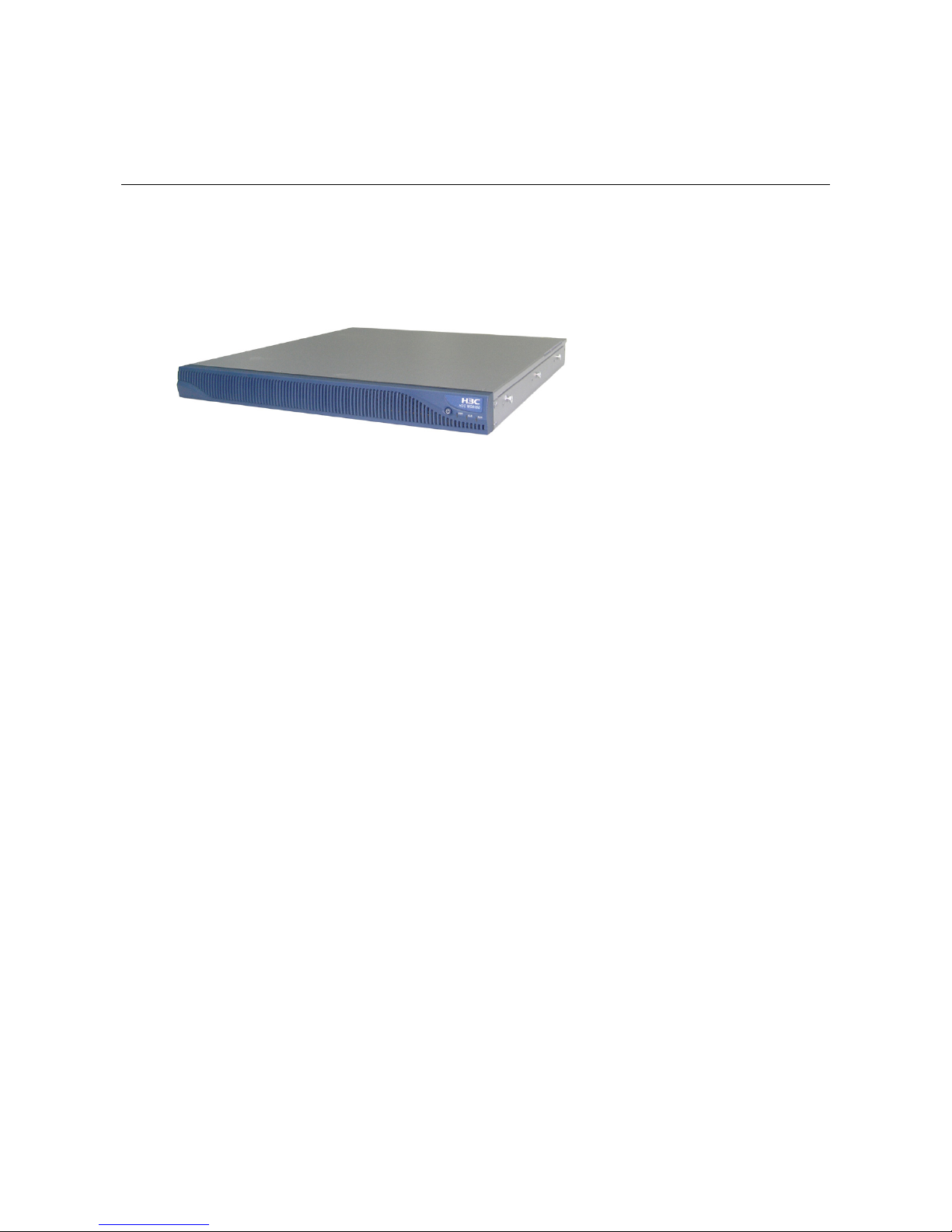
1 Overview
H3C MS8000 (hereinafter referred to as the MS8000) is a media switch se rver developed by Hangzhou
H3C Technologies Co., Ltd. (H3C). It is an important component in the H3C IP video surveillance
system (iVS) solution.
Figure 1-1 shows its appearance.
Figure 1-1 MS8000 appearance
Features
Forwarding and distribution of real-time audio and video steams
The MS8000 receives unicast/multicast media steams from encoders and forwards replica of the
streams to decoder client for replay. Up to 1024 copies for each stream are supported.
The MS8000 can be deployed flexibly as needed, enhancing the iVS solution.
z Placed at the iVS edge, the MS8000 acts as a gateway to transform the multicast media streams to
unicast media streams.
z Placed inside the iVS, the MS8000 is to distribute unicast media streams.
VOD of the audio and video history data
The MS8000 is compatible with the all the H3C series of video encoders. It reads the audio and video
history data from the IP SAN (storage area network), and then sends the data in the standard RTP
streams to the decoder client for decryption and replay.
RTSP (real-time streaming protocol) i s used for the MS8000 a nd V OD client to control su ch operation s
as play, pause, forward.
The MS8000 authenticates users that initiate the VOD requests. It obtains data from the IP SAN and
sends it to the legal users. This prevents unauthorize d users from accessing the data.
Convenient management through Web interfaces
The MS8000 provides Web-based management, such as software version management,
communication protocol parameter management, and log management, thus facilitating the
maintenance and management of the system.
Page 8
1-2
Appearance
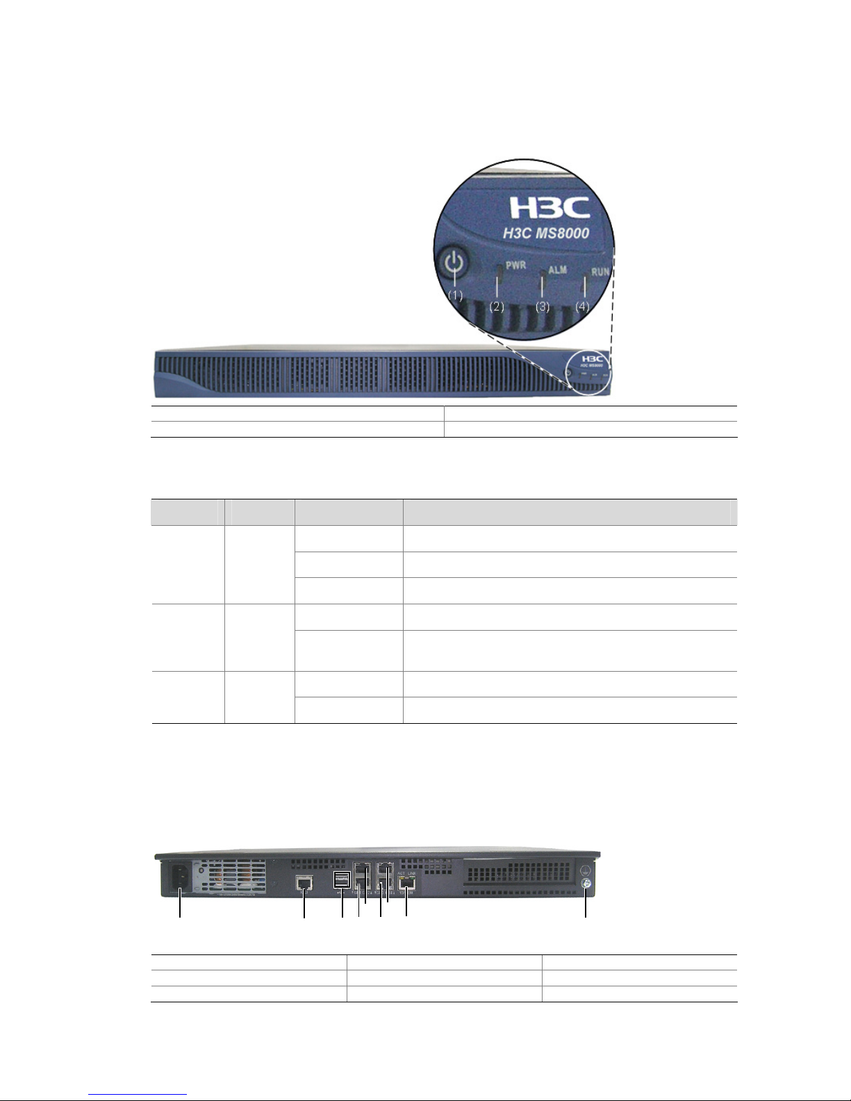
Front View
Figure 1-2 MS8000 front view
(1) Power switch (2) Power LED (PWR)
(3) Alarm LED (ALM) (4) Running LED (RUN)
Table 1-1 Description for the LEDs
LED Color Status Meaning
Blinking The MS8000 is starting up.
Steady on The MS8000 has started up.
PWR Green
Off The MS8000 is not powered on.
On Hardware exceptions occur to the system.
ALM Red
Off
The MS8000 is performing power-on self-test (POST),
or no alarms exist.
Steady on
The MS8000 is operating normally.
RUN
Green
Off The MS8000 is operating abnormally.
Rear View
Figure 1-3 MS8000 rear view
(1) (2)
(5) (7)
(4) (6) (8)
(3)
(9)
(1) (2)
(5) (7)
(4) (6) (8)
(3)
(9)
(1) Power input (2) Serial interface (3) USB port (2)
(4) Gigabit Ethernet port (eth1) (5) Gigabit Ethernet port (eth2) (6) Gigabit Ethernet port (eth3)
(7) Gigabit Ethernet port (eth4) (8) Ethernet port (eth0) (9) Groundi ng screw
Page 9

1-3
Technical Specifications
Table 1-2 MS8000 hardware specifications
Item Description
CPU 2.8 GHz 2M Cache Xeon Processor
Memory (RAM) 2 GB
Physical dimensions (H ×
W × D)
43.6 × 430 × 503.4 mm (1.72 × 16.93 × 19.82 in.)
Weight 9.4 kg (20.72 lb)
Input voltage 100 VAC to 127 VAC/200 VAC to 240 VAC, 50 Hz/60 Hz
Max power consumption 400 W
Serial interface One RJ-45 connector with the default baudrate being 115200 bps
Operating temperature 5°C to 40°C (41 °F to 104° F)
Storage temperature –40°C to +70°C (–40°F to + 158°F)
Relative operating
humidity (noncondensing)
20% to 80%
Relative storage humidity
(noncondensing)
10% to 90%
Table 1-3 MS8000 software specifications
Item Description
Real-time stream forwarding and distribution capability 640 Mbps
History data VOD capability 128 Mbps
VOD control protocol RTSP
Page 10
2-1
2 Device Installation
Precautions
To ensure its proper operation and extend its longevity, consider the precautions when installing the
MS8000:
z Install the MS8000 indoors.
z Install the MS8000 in a place with good ventilation, especially around the heat dissi pation holes. Do
not place any objects on the device.
z Make sure the requirements on the environment temperature and humidity, and the power supply
are met.
z Ground the MS8000 in equal-potential wiring. The grounding device must meet the requirements
for anti-interference and equipment safety, and shall not form short-circuit or contact with the
neutral wire of the high-voltage electrical network.
z Keep the working environment clean. Dust buildup will cause electrostatic adsorption, which may
not only shorten the life of the MS8000, but also incur operation failure.
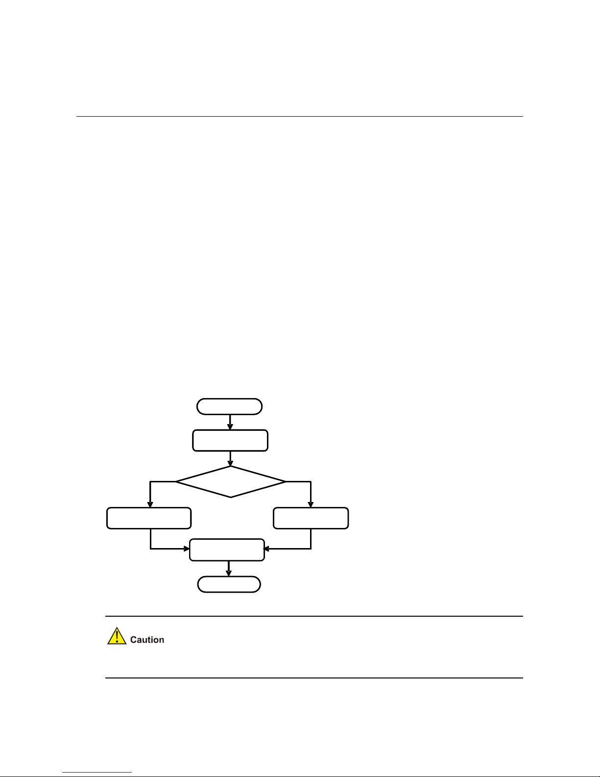
Installation Flow
Figure 2-1 Installation flow
Install the MS8000
in a rack
Select the
installation place
Start
Install the MS8000
on a workbench
Check
before installation
Finish
Check after
installation
Install the MS8000
in a rack
Select the
installation place
Start
Install the MS8000
on a workbench
Check
before installation
Finish
Check after
installation
Before installing the MS8000, make sure it is disconnected from the power source.
Page 11

2-2
Before Installation
Before installing the MS8000:
z Verify the equipment model, and the type and quantity of accessories against the packing list.
z Make sure you have reviewed the content in the "Precautions" section on page 2-1, and all
requirements are met.
z Prepare a flathead screwdriver and a Phillips screwdriver.
The directions of front, rear, left, right, and bottom in this manual are referenced when the MS8000 is
placed with the front panel before you.
Do not remove the dismantlement-preventive seal on the chassis cover of an MS8000 without
permission. If you want to open the chassis, contact the local agent of H3C for help. Otherwise, H3C
shall not be held liable for any consequence caused thereby.
Installing the MS8000 in a Rack
You can install your MS8000 to a standard 19-inch rack manufactured by H3C or other vendors (the
rack should be able to bear the weight of the MS8000). The following sections use an H3C standard
19-inch rack as an example.
Installation Preparation
z Check the grounding and stability of the rack, determine the position on the rack that the MS8000 is
to be installed to, and make sure there is no obstacle inside or near the ra ck which may hamper the
installation.
z Move the MS8000 near to the rack for installation.
Installation Procedure
Step1 As shown in Figure 2-2, fix the mounting brackets to the two sides of the MS8000 chassis with screws.
Press the inner slide rails (left and right) to the screws on the chassis in the direction indicated by ①,
and pull the slide rails in the direction indicated by ② to fix them to the chassis.
Page 12
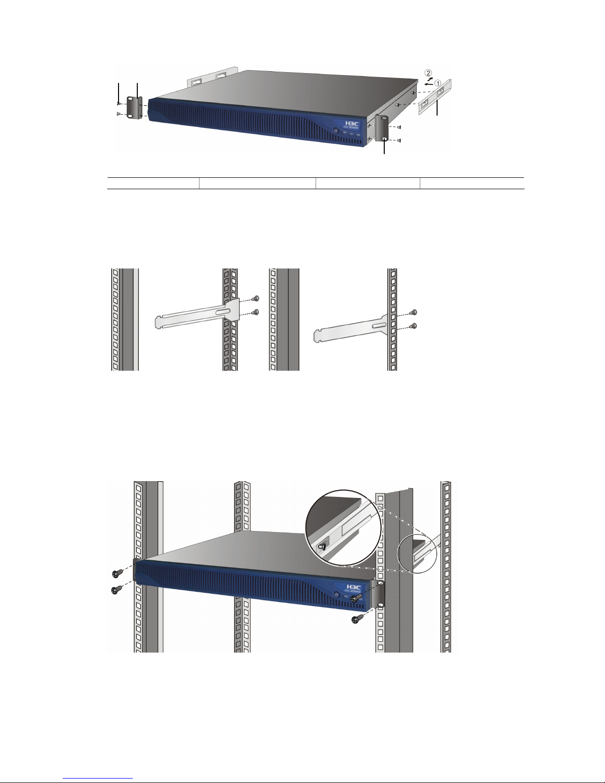
2-3
Figure 2-2 Install mounting brackets and inner slide rails
(1)
(2)
(3)
(4)
(1)
(2)
(3)
(4)
(1) Four screws (2) Mounting brackets (3) Slotted hole (4) Inner slide rail
Step2 As shown in
Figure 2-3, fix the outer slide rails to the rack posts on the same height at the two rear sides
of the rack with screws.
Figure 2-3 Install outer slide rails
Step3 Lift the MS8000 to align the inner slide rails with the outer slide rails, and push the MS8000 slowly inside
the rack along the slide rails until the mounting brackets contact the rack post s at the front sides of the
rack. Fix the mounting brackets to the rack posts using the screws and captive nut s, as shown in
Figure
2-4.
Figure 2-4 Install the MS8000 to the rack
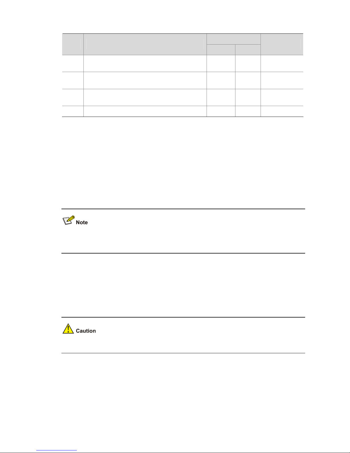
Verification
After installing the MS8000 to the rack, check the items listed in Table 2-1. All results should be Yes.
Page 13
2-4
Table 2-1 Verification list for MS8000
Result
No. Item
Yes No
Remarks
1
The mounting brackets and inner slide rails are
fixed to the MS8000 tightly.
2
The MS8000 is installed at an appropriate
position.
3
The outer slide rails are fixed on the rack posts at
the rear of the rack.
4 The inner and outer slide rails are conn ected well.
Installing the MS8000 on a Workbench
If you do not have a standard 19-inch rack, you can install your MS8000 on a workbench.
Installation Preparation
z Make sure the workbench is sturdy enough to hold the MS8000, its accessories and the cables.
z Make sure the workbench is well grounded and is stable.
The MS8000 is shipped with feet. You need to remove the stickers from the feet and fasten the feet to
the appropriate positions on the bottom of the MS8000.
Installation Procedure
Step1 Move the MS8000 in front of the workbench.
Step2 Lift the MS8000 a little higher than the workbench and place it on the workbench.
To ensure effective heat dissipation, keep at least a clearance of 10 cm (3.94 in.) around the MS8000.
Installing the Cables
Cabling Requirements
The principle of cabling is that service cables (such as network cable) should be separated from the
power cables. You can bundle the long cables with cable ties, and stick a label to a cable for indication.
Page 14

2-5
If your MS8000 is installed in a 19-inch rack, you can lay the cables either over the top or below the
bottom of the rack according to the actual situation (whether the signal cables of the equipment room
are wired on the rack top or below the rack bottom).
z Do not bundle cables near the heat dissipation hole to avoid speedy aging of cables.
z Fix the cables near the MS8000 and keep the cables loose between the interfaces and the fasten
points.
Connecting the Ground Wire
To ensure human and equipment safety against lightning and interference, the MS8000 must be
grounded reliably.
Step1 As shown in
Figure 2-5, connect one end of the ground wire to the grounding screw of the MS8000.
Figure 2-5 Connect the ground wire
(1)(1)
(1) Ground wire
Step2 Connect the other end of the ground wire to a ground point.
Generally, a rack has a set of ground bars, where you can connect the ground wire. In practice, you may
connect the ground wire properly according to the conditions.
Page 15

2-6
Connecting the AC Power Cable
The MS8000 ships with a cable retention clip. Before connecting the power cable, install the cable
retention clip first.
Step1 Ensure that the power switch of the MS8000 is off, and the power cable retention clip has been inst alled
on the MS8000 correctly.
Step2 Connect one end of the power cable to the power interface on the MS8000 rear panel, use the
cable-retention clip to fasten the power cable, and connect the other end of the power ca ble to a power
socket.
Figure 2-6 Connect the power cable
You are recommended to connect the power cable to a single-phase three-wire power socket. You
need to make sure that the neutral point of the power socket is properly grounded. Generally, the
neutral points in buildings are already grounded in construction.
Connecting the Console Cable and Network Cable
You can connect the console cable as per your requirements.
As shown in
Figure 2-7, connect the console cable and network cable. As for the other end of the
network cable, you can connect it according to the actual condition on the installation site, and the
connection is omitted here.
Figure 2-7 Connect console cable and network cable
(1) PC (2) Console cable (3) Network cable
Page 16

2-7
After Installation
Before performing the check, make sure that the device is powered off, to avoid bodily injury or
equipment damage caused by incorrect cable connection.
After the MS8000 is installed, check the followi ng:
z The MS8000 is installed securely with all screws fixed tightly.
z No objects are placed on the MS8000.
z The power to use meets the requirements of the MS8000.
z The MS8000 is grounded properly, and all cables are connected correctly and firmly. No outdoor
cabling is allowed.
If all the above check results satisfy the requirements, turn on the power switch to st art up the MS8000.
Page 17

3-1
3 Initial Configuration
Perform the initial configuration under the guide of H3C technicians to avoid exceptions.
Prerequisites
Before logging in to the MS8000, make the following prerequisite tasks:
z Plan the system configuration, such as the MS8000 IP address and device ID.
z MS8000 is operating normally.
z The MS8000 is well connected to the video management server (VM), storage device, and client
PC.
z The client PC is installed with the SSH tool such as Putty, Microsoft Internet Explore 6.0 or higher
version.
z The recommended display resolution of the client PC is 1024 × 768.
z No proxy is set for the IE browser on the client PC.
Configuration Tasks
z The MS8000 is installed in the Linux operating system. Its default settings are: msserver1 for the
hostname, 192.168.0.30/24 for the IP address on eth1 (as shown in
Figure 1-3), 192.168.0.1 for
the gateway IP address, root for username, and passwd for the password.
z Use the SSH tool with port 22 to log in to the command line interface for initial configuration.
z If you use the Web interface for initial configuration, refer to the "Login and Logout" section on page
4-1 for instructions.
Follow these steps to perform the initial configuration tasks.
Table 3-1 Initial configuration task list
Task Remarks
Configuring Host Name
Configure the host name for the MS8000. The host name uniquely
identifies the host.
Configuring the Network
Configure IP address and subnet mask for the MS8000 to
communicate with the external devices.
Page 18

3-2
Task Remarks
Configuring Parameters for the
MS8000 Services
Configure operation parameters for the MS8000 services.
Restarting MS8000 Services Starting the MS8000 Services.
Configuring Host Name
If multiple MS8000s are installed in the network, you have to configure their hostnames. Suppose the
new host name is msserver, follow these steps below to configure:
Step1 Display the current host name of the MS8000.
[root@msserver1 ~]# hostname
msserver1
Step2 Edit the network configuration file and restart the system to make the changes take effect.
In Linux, use the vi command to edit the network configuration file.
[root@msserver1 ~]# vi /etc/sysconfig/network
Type i to enter the edit mode of the configuration file. Set the file content to HOSTNAME=msserver, and
then save to exit.
After the modification, press Esc, and then enter :wq! if you want to save the changes and exit, or
enter :q! if you want to exit without saving the changes.
Step3 Use the hostname command to make the host name change take effect.
[root@msserver1 ~]# hostname msserver
Step4 Edit the hosts file so that the Web server can identify the host name.
[root@msserver ~]# vi /etc/hosts
Set the file content to 127.0.0.1 localhost.localdomain msserver localhost.
Do not change the MS8000 host name after you have configured it successfully, otherwise, system may
operate improperly.
Configuring the Network
Follow these steps to configure the network settings as needed.
Step1 Check the network connections.
Page 19

3-3
Use the ethtool eth1 command to check that the settings of interface eth1, the link speed, and
dual-duplex status are correct. The "Link detected:yes" in the display means that the connection is up. If
there is no such display, check the cable connection.
[root@msserver ~]# ethtool eth1
Settings for eth1:
Supported ports: [MII]
Supported link modes: 10baseT/Half 10baseT/Full
100baseT/Half 100baseT/Full
1000baseT/Half 1000baseT/Full
Supports auto-negotiation: Yes
……
Current message level: 0x00000007 (7)
Link detected: yes
Step2 Display the current configuration.
Use the ifconfig eth1 command to display the current configuration.
[root@msserver ~]# ifconfig eth1
eth1 Link encap:Ethernet HWaddr 00:04:23:CB:8B:74
inet addr:192.168.0.30 Bcast:192.168.0.255 Mask:255.255.255.0
inet6 addr: fe80::204:23ff:fecb:8b74/64 Scope:Link
UP BROADCAST MULTICAST MTU:1500 Metric:1
RX packets:1171606 errors:0 dropped:0 overruns:0 frame:0
TX packets:202306 errors:0 dropped:0 overruns:0 carrier:0
collisions:0 txqueuelen:1000
RX bytes:192266150 (183.3 MiB) TX bytes:46015753 (43.8 MiB)
Interrupt: 169
Step3 Change the configuration.
Suppose the IP address of the MS8000 is 192.168.112.186 with the subnet mask being 255.255.255.0,
and the default gateway IP is 192.168.112.1. Perform the following configuration.
In Linux, use the following command to enter the edit status of configuration file for the eth1 port.
[root@msserver ~]# vi /etc/sysconfig/network-scripts/ifcfg-eth1
z Set BOOTPROTO to static, which means that static IP assignment mode is used.
z Set IPADDR to 192.168.112.186.
z Set NETMASK to 255.255.255.0
z Set GATEWAY to 192.168.112.1.
z Set ONBOOT to yes, which means the network configurations on this interface take effect after the
network services are restarted.
After that, save the configuration and restart the network services to make the new configuration take
effect.
[root@msserver ~]# service network restart
Page 20

3-4
z The device IP must be unique in the network.
z After the modification, press Esc, and then enter :wq! if you want to save the changes and exit, or
enter :q! if you want to exit without saving the changes.
z After the services restarts, the IP address is changed. Log in to the MS8000 using the new IP
address.
Configuring Parameters for the MS8000 Services
After the MS8000 software is installed, a configuration file ms.conf has been generated under the
directory /usr/local/etc. Before starting the MS8000 services, configure the parameters.
z It is recommended only professional technicians perform the operation to change the MS8000
service parameters. Improper configuration may cause malfunctions. For the non-professionals to
change parameters, contact H3C for technical support.
z After modifying the service parameters, restart the MS8000 to make the changes take effect.
Main parameters in the ms.conf configuration file are described in
Table 3-2. For other parameters not
mentioned in this table, it is recommended to use the default settings.
Table 3-2 Main parameters of the MS8000 services
Item Description
VMIP
IP address of the VM call control service for communication with the
MS8000.
MyID
MS8000 ID.
Note: It must be identical with that on the VM if the VM is to communicate
with the MS8000.
MyVmpPort Port for listening to the protocol packets from the VM. It defaults to 6060.
MyRtspServerIP
IP address for listening to the RTSP protocol packets. It must be an IP
address of the MS8000, and it is reachable to the VC client.
MyRtspServerPort Port for listening to the RTSP protocol packets. It defaults to 554.
Language
Sets the language of the user interfaces.
It is necessary to change the value to 2 so that the user interfaces are
displayed in English.
Use the vi command in Linux to change the MS8000 service parameters. Open the configuration and
enter its edit mode for modification.
[root@msserver ~]# vi /usr/local/etc/ms.conf
Page 21

3-5
After opening the configuration file, type i to enter the edit status of the file. After the modification, press
Esc, and then enter :wq! if you want to save the changes and exit, or enter :q! if you want to exit without
saving the changes.
Restarting MS8000 Services
Step1 After configuration, use the msserver restart command to restart the MS8000 services to make the
configuration take effect.
[root@msserver ~]# msserver restart
Step2 After that, use the msserver status command to display the status of all the services.
[root@msserver ~]# msserver status
httpd is running.
msvod is running.
mssnmp is running.
msipmi is running.
msserv is running.
mslogd is running.
iscsid is running.
msdaemon is running.
Page 22

4-1
4 Web-Based Management
The MS8000 provides Web interfaces for configuration management, includin g:
z System Management
z Log Management
z User Management
z Traffic Statistics
z Two categories of users are in the MS8000: super administrator and common administrator. They
operate based on the permissions. The following sections take the Web interface for super
administrator for illustration. For more information about users, refer to the "
User Management"
section on page
4-9.
z The parameters displayed in grey on the configuration pages cannot be modified.
Login and Logout
Logging In to the System
For the first-time login, use admin as both the username and password to log in as super administrator.
To log in to the Web interface:
Step1 Launch the IE browser on the client PC, and enter the IP address of the MS8000 in the address bar.
Step2 On the login page, type the username and password, and click OK to enter the Web interface similar to
Figure 4-1.
Page 23

4-2
Figure 4-1 Layout of the Web interface
z The menus in the navigation area and tab in the operation area provide entries to specific
configuration pages.
z After your first-time login, you are recommended to modify the login password. For details, refer to
the "
Changing Password" section on page 4-11.
z If you are idle without operation for 10 minutes, the system logs you out automatically. Log in again
for operations.
Logging Out
To log out of the MS8000, you can click Quit in the navigation tree and confirm your operation.
System Management
Introduction
The system management allows you to view version information, communication protocol parameters,
export and import the configuration, upgrade software, and manage devices.
Select System Management to enter the page as shown in
Figure 4-2.
Figure 4-2 System management
Page 24

4-3
Displaying Version Information
Select System Management. The page displays the Software Version by default.
Configuring Communication Protocol Parameters
On the Communication Protocol page, you can configure the protocol parameters of the MS8000 to
communicate with the VM8000.
To configure the communication protocol parameters, follow these steps:
Step1 Select System Management, and then select the Communication Protocol tab to enter the page as
shown in
Figure 4-3.
Figure 4-3 Communication protocol management
Step2 Type the IP address of the VM call control service a nd the ID of the MS8000, as described in
Table 4-1.
Table 4-1 Description of communication protocol parameters
Item Description
VM Status Status of the connected VM server
CC IP IP address of the call control service on the VM server
MS ID
MS8000 ID, used to identify the media switch server uniquely in the video
surveillance system
Note; The MS ID must be unique in the whole network.
Step3 Click Set to complete the configuration. The system displays the result.
Exporting/Importing Configuration
Export/import is a backup scheme. The exported/imported data cont ains the MS8000 configuration file.
z It is recommended to export and save the most recent MS8000 configuration, especially after the
MS8000 configuration has changed.
z When the MS8000 is experiencing an unrecoverable error, you can import the configuration file
that has been exported previously to restore the system. This avoids massive repeated
configurations.
To export/import the configuration, follow these steps:
Step1 Select System Management, and then select the System Configuration tab to enter the page as
shown in
Figure 4-4.
Page 25

4-4
Figure 4-4 Configuration management
Step2 If you want to export the current system configuration, click Export. In the pop-up dialog box, select
Save to bring up another dialog box. Select the directory to save the file and click Save.
Step3 If you want to import the system configuration click Browse. In the pop-up dialog box, select the data to
be imported and click Open. Then click Import. The system displays the operation result later.
After the configuration is imported, the MS8000 services will restart to make the imported configuration
take effect.
Upgrading Software
z Before upgrading the software, back up the current configuration file. For more information, ref er to
the "
Exporting/Importing Configuration" section on page 4-3.
z Do not power off the device during upgrading, otherwise, the MS8000 may operate improperly.
z After the software is upgraded, the MS8000 services will restart. You have to re-log in to the Web
interface for further configuration.
To upgrade the MS8000, follow these steps:
Step1 Select System Management, and then select the Software Update t ab to e nter the page as shown in
Figure 4-5.
Figure 4-5 Software update
Step2 Click Browse. On the pop-up dialog box, select the MS8000 upgrading package, and click Open.
Step3 Click Update to start the operation. The system displays the result later.
Page 26

4-5
Displaying Device Information
The MS8000 allows you to display the current information of the server. You can check the information
in real time against the normal range. This greatly facilitates the server maintenance.
Select System Management, and then select the Device Status tab to enter the page as shown in
Figure 4-6.
Figure 4-6 Device status list
Parameters of the device status are described in
Table 4-2.
Table 4-2 Parameters of the device status
Field Description
Item
Component name of the device.
Current
Value of the current running status of the component.
Lower Critical
Lower critical threshold of the running status of the component.
Note: When the actual value is under this threshold, the device
experiences a sever problem. Please contact H3C for technical help.
Lower Non-Critical
Lower non-critical value of the running status of the component.
Note: When the actual value is between this threshold and the lower
critical threshold, the device experiences a common error. Please check
the corresponding component.
Up Critical
Upper critical threshold of the running status of the component.
Note: When the actual value is under this threshold, the device
experiences a sever problem. Please contact H3C for technical help.
Up Non-Critical
Upper non-critical threshold of the running status of the component.
Note: When the actual value is between this threshold and the upper
critical threshold, the device experiences a common error. Please check
the corresponding component.
To view the latest device information, click Refresh.
Page 27

4-6
Log Management
Introduction
The logs record key events that happened in the MS8000. T wo types of logs are re corded, system logs
and operation logs.
z System logs: Record events that occurred during the MS8000 operation.
z Operation logs: Record configuration made by the administrator.
The log management allows you to display the system logs, display the operation logs, query, and
export logs.
Select Log Management to enter the page as shown in
Figure 4-7.
Figure 4-7 Log management
Viewing System Logs
The system logs are classified into 7 levels, emergency, alert, critical, error, warning, notice, and
information. The first two are displayed red in the interface.
The meaning of the log levels are:
z Emergency: Indicates a severe error that needs to be solved immediately.
z Alert: Indicates an error that needs to be solved immediately.
z Critical: A critical error needs to be solved as soon as possible.
z Error: An error needs your attention, but is not critical.
z Warning: Errors exist in the system and they may affect some functions.
z Notice: Event needs your attention.
z Information: Information not requiring attentions.
Select Log Management. The system displays the Sy stem Log t ab by default, listing the system logs.
Figure 4-8 View system logs
Page 28

4-7
z Click Refresh to view the latest log information.
z Only the logs of the past three months can be queried and displayed.
Displaying Operation Logs
Select Log Management, and then select the Operation Log tab to enter the page displaying the
operation logs.
Figure 4-9 Operation log list
z Click Refresh to view the latest log information.
z Only the logs of past three months can be queried and displayed.
Querying Logs
You can query logs based on the log type, event level, and the generation time.
To query logs, follow these steps:
Step1 Select Log Management, and then select the Query tab to enter the page, as shown in
Figure 4-10.
Page 29

4-8
Figure 4-10 Query logs
Step2 Specify the query conditions.
You can specify the event level if you select to query system logs. This is not available for operation
logs.
Step3 Click the calendar icon
and set the start and end time as required. The start time must be ahead of
the end time.
Step4 Click Query. The system displays the result matching the query conditions.
Exporting Logs
The logs record the system running status. When errors occur in the system, you can export the logs for
troubleshooting.
To export logs, follow these steps:
Step1 Select Log Management, and then select the Export tab to enter the page, as shown in
Figure 4-11.
Figure 4-11 Export logs
Step2 Specify the start and end time by clicking the calendar icon.
z If you leave the end time blank, the current time is used as the end time.
z The time span cannot exceed one month.
Page 30

4-9
Step3 Click Export. A dialog box appears.
Step4 Choose to save the file and then select the directory for the file to be saved in the pop-up Save AS
dialog box. Click Save.
The logs are saved locally in compressed files. Unzip the file and open the file in text format to view the
logs.
User Management
Introduction
The administrators of the MS8000 falls into two categories: super administrator and common
administrator.
z Super administrator: Owns the rights to execute all the configuration and management operations,
including creating, editing, and deleting common administrators. In addition, the super
administrator has the preempt login right over other users, that is, the login of super administrator
kicks out other users that have logged in.
z Common administrator: Owns the rights to execute the configuration and query operations.
The user management includes adding and deleting users, resetting and changing passwords.
z The system has only one super administrator with the user name and password being admin.
z Up to 7 common administrators can be created.
Select User Management to enter the page as shown in
Figure 4-12.
Figure 4-12 User management
Page 31

4-10
Adding a User
Only the super administrator has the permission to add users to the system.
To add a user, follow these steps:
Step1 Select User Management to enter the page listing the users.
Step2 Click Add to enter the page for adding a user, as shown in
Figure 4-13.
Figure 4-13 Add a user
Step3 Input the information as required, such as the user name and password.
Step4 Click OK.
Deleting a User
z Only the super administrator has the permission to delete users from the system.
z Super administrator is the default user and cannot be removed.
Selecting the check box in the table heading of the user list will selects all the users excluding the super
administrator.
To delete a user, follow these steps:
Step1 Select User Management to enter the page for listing the users.
Step2 Select one or more users to remove.
Step3 Click Remove. A dialog box appears, asking for confirmation.
Page 32

4-11
Step4 Input yes in the confirmation dialog box and click OK. The system performs the operation and displays
the result later.
Resetting Password
Only the super administrator has the right to reset passwords for users. Common administrators can
ask the super administrators to reset the passwords if they forget their passwords.
To reset a password, follow these steps:
Step1 Select User Management to enter the page for listing the users.
Step2 Select one or more users to reset their passwords.
Step3 Click Reset Password to enter the page for editing the password of a user.
Step4 Specify the new password. Click OK. The system performs the operation and displays the result later . If
you select multiple users to reset password, you can click Continue after the first is changed
successfully.
Changing Password
z It is recommended to change your default login password after you have logged in for the first time.
z Use the new password the next time you log in to the system.
To change the password, follow these steps:
Step1 Select User Management, and then select the Change Password tab to enter the page for changing
the password.
Step2 Type in the old password, the new password and then the confirm password.
Step3 Click OK.
Traffic Statistics
Introduction
The MS8000 Web interface displays the current service status, including the VOD service status and
forwarding service status.
Select Traffic Statistics to enter the page as shown in
Figure 4-14.
Page 33

4-12
Figure 4-14 Traffic statistics
Displaying VOD Traffic Statistics
Select T ra ffic St atistics to enter the pag e as shown in Figure 4-14. The VOD T raffic t ab is displayed by
default. The information about the VOD service status is displayed, including the media URL, speed
rate, and client IP address.
If you want to view the latest VOD traffic statistics, click Refresh as shown in Figure 4-14.
Displaying Forwarding Traffic Statistics
Select Traffic Statistics, and then select the Forwarding Traffic tab to enter the page as shown in
Figure 4-15. The page displays the statistics abo ut the forwarding traffic.
Figure 4-15 Forwarding traffic statistics
If you want to view the latest forwarding statistics, click Refresh as shown in Figure 4-15.
If you want to view the details of a record, click the source IP/Port link in the list. The details are
displayed as shown in
Figure 4-16.
Page 34

4-13
Figure 4-16 Forwarding traffic statistics
Page 35

5-1
5 Compliance and Safety Manual for MS8000
Regulatory Compliance Information
Regulatory compliance standards
Table 5-1 Regulatory compliance standards
Discipline Standards
EMC
z FCC Part 15 (CFR 47) CLASS A
z ICES-003 CLASS A
z VCCI-3 CLASS A
z VCCI-4 CLASS A
z CISPR 22 CLASS A
z EN 55022 CLASS A
z AS/NZS CISPR22 CLASS A
z CISPR 24
z EN 55024
z EN 61000-3-2
z EN 61000-3-3
z EN 61000-4-4
z EN 61000-4-5
z EN 61000-4-6
z EN 61000-4-8
z EN 61000-4-11
z GB 9254
z GB 17625.1
z YD/T993
Safety
z UL 60950-1
z CAN/CSA C22.2 No 60950-1
z IEC 60950-1
z EN 60950-1/A11
z AS/NZS 60950
z EN 60825-1
z EN 60825-2
z FDA 21 CFR Subchapter J
z GB 4943
European Directives compliance
LVD/EMC Directive
MS8000 product complies with the European Low Voltage Directive 2006/95/EC and EMC Directive
2004/108/EC.
A copy of the signed Declaration of Conformity can be downloaded from:
http://www.h3c.com/portal/Technical_Documents
Page 36

5-2
WEEE Directive–2002/96/EC
The product this manual refers to is covered by the Waste Electrical & Electronic Equipment (WEEE)
Directive and must be disposed of in a responsible manner.
USA regulatory compliance
FCC Part 15
MS8000 complies with Part 15 of the FCC Rules. Operation is subject to the following two conditions:
z This device may not cause harmful interference.
z This device must accept any interference received, including interference that may cause
undesired operation.
If the customer modifies the equipment without the authorization of H3C, which directly or indirectly
contribute to the equipment incompliance with FCC requirements for Class B (Class A) digital devices,
H3C is not liable for such interference problem and the expenses incurred therefrom shall be covered
by the customers.
This equipment has been tested and found to comply with the limits for a Class A digital device,
pursuant to Part 15 of the FCC Rules. These limits are designed to provide reasonable protection
against harmful interference when the equipment is operated in a commercial environment. This
equipment generates, uses, and can radiate radio frequency energy and, if not installed and used in
accordance with the instruction manual, may cause harmful interference to radio communications.
Operation of this equipment in a residential area is likely to cause harmful interference in which case the
user will be required to correct the interference at his own expense.
Canada regulatory compliance
ICES-003
This Class A digital apparatus complies with Canadian ICES-003.
Cet appareil numérique de la classe A est conforme à la norme NMB-003 du Canada.
Page 37

5-3
Japan regulatory compliance
VCCI
MS8000 complies with the requirements of VCCI Class A Information Technology Equipment (ITE).
Warning: If this equipm ent is used in a domestic environment, radio distu rbance may arise. When such
trouble occurs, the user may be required to take corrective actions.
产品符合中国 CCC 认证要求
MS8000 产品符合国标 GB9254 Class A YD/T993 和 GB4943 的要求。
此为 A 级产品,在生活环境中,该产品可能会造成无线电干扰。在这种情况下,可能需要用户对其干扰
采取切实可行的措施。
Safety Information Sicherheits informationen
安全信息
Overview Überblick 概述
This section introduces part of the safety precautions that should be followed during the inst allation and
maintenance of the equipment. And for the safety statements and warnings, there followed the
translations of both German and Chinese to comply with the national requirements.
Dieser Abschnitt macht Sie mit den Sicherheitsvorschriften vertraut, die Sie bei der Installation und
Instandhaltung der Ausrüstung beachten müssen.
本章节介绍了在安装、日常维护本系列设备时,必须遵循的安全预防规范。
Before any operation is performed, please read the operation instructions and precautions carefully to
minimize the possibility of accidents. The Note, Caution, Warning and Danger items in other manuals
do not cover all safety precautions that should be followed. They are only the supplements to the safety
precautions for operations as a whole. Therefore, the personnel in charge of the installation and
maintenance of the products are required to understand these basics of safety operation.
In performing various operations, please follow the local safety regulations. The safety precautions
introduced in the product manuals are supplementary and subject to the local safety regulations.
When various operations are executed on the products, the precautions and special safety instructions
provided with the products must be followed to the full.
The personnel in charge of the installation and maintenance of the products must be trained as
professionals to master the proper operating methods and all safety precautions. Only the trained and
qualified personnel can perform operations such as equipment installation and maintenance.
Page 38

5-4
Anmerkung
Lesen Sie bitte alle Arbeitsanweisungen und Sicherheitvorschriften sorgfältig durch, bevor Sie mit dem
Arbeiten beginnen. Nur durch Beachtung dieser Hinweise lässt sich das Unfallri si ko mi nimie ren. Die i n
anderen Handbüchern aufgeführten Symbole Anmerkung, Achtung, Warnung und Gefahr
beinhalten nicht alle zu beachtenden Sicherheitvorschriften. Sie dienen lediglich der Ergänzung.
Deshalb muss sich das für die Installation und Insta ndhaltung der Ausrü stung verantwortliche Personal
mit allen Sicherheitshinweise vertraut machen.
Bei der Durchführung der verschiedenen Arbeitsschritte müssen außerdem die örtlichen
Sicherheitsvorschriften beachtet werden. Die in den Handbüchern de r einzelnen Produkte aufgef ührten
Sicherheitshinweise sind Ergänzungen und unterliegen den nationalen Sicherheitsvorschriften.
Während der Arbeit mit den Produkten sind deshalb grundsätzlich alle Sicherheitsvorschriften und
spezifischen Sicherheitshinweise genau zu beachten.
Das für die Installation und Instandhaltung der Produkte verantwortliche Pesonal muss geschult
werden, um alle Sicherheitsvorschriften zu kennen und die richtigen Arbeitsmethoden anwenden zu
können. Nur geschultes und qualifiziertes Personal kann die Installation und Instandhaltung in korrekter
Weise durchführen.
为了避免可能发生的事故,请在进行任何操作前,仔细阅读设备操作手册和本章节的安全规范。手册中 出
现的说明、注意、警告、危险,不能涵盖所有的安全预防,仅仅是在整个操作过程中的安全提示和补充。
因此,负责安装和日常维护本设备的人员必须具备安全操作基本技能。
操作人员要按照当地的安全规范进行操作。出现在产品手册中的安全预防措施仅仅是当地安全规范的补
充。
在操作本设备时,请认真执行产品手册规定的安全规范。
设备安装、维护人员必须通过专业培训,并且掌握足够的操作技能和安规预防意识。只有专业人员才能
担任本设备的安装和维护工作。
Conventions Used Symbole Erläuterung 应用惯例
The symbols in this manual are shown in the following t able. They ar e used to rem ind the reade r of the
safety precautions during equipment installation and maintenance.
Die Symbole in diesem Handbuch verwendeten sind in der folgenden Tabelle dargestellt. Diese
Symbole sollen das Personal während der Installation und Instandhaltung der Ausrüstung an die
Wichtigkeit der im Handbuch aufgeführten Sicherheitsvorschriften erinnern.
以下表格中的安全标识,是用来提示读者在进行设备安装和维护时的安全预防要求。
Page 39

5-5
Table 5-2 Safety symbol and description Sicherheitssymbole und Beschreibung安全标识和描述
Safety Symbol
Symbole
安全标识
Description
Erläuterung
描述
Generic alarm symbol: To suggest a general safety concern
Alarm: Hinweis auf ein generelles Sicherheitsproblem
一般注意标识:用于一般安全提示
ESD protection symbol: To suggest electrostatic-sensitive equipment.
ESD-Schutz: Hinweis auf Beschädigung infolge elektrostatischer Entladung
防静电标识:用于表示静电敏感的设备
General Requirements Allgemeine Anforderungen 通用要求
In order to reduce the technically unavoidable residual risk to a minimum, it is imperative to follow the
rules below:
Um das technisch bedingte Restrisiko auf ein Minimum zu begre nzen, ist es unbedingt erforde rlich, die
folgenden Regeln zu beachten:
为了避免对人和设备造成伤害,请认真执行下列要求:
z Read all the instructions before operation.
z Lesen Sie alle Anweisungen sorgfältig durch, bevor Sie mit dem Arbeiten beginnen.
z 在进行操作前仔细阅读手册内容。
z When installing the unit, always make the ground connection first and disconnect it last.
z Beachten Sie, dass bei der Installation des Systems stets zuerst die Erdverbindung angebracht
wird und das die Erdverbindung stets als letztes getrennt wird.
z 进行设备安装时,必须确保接地连接是最先连接和最后断开。
z Do not block ventilation openings while the system is on, and keep at least 5 cm distance from
ventilation openings and walls or other things which may block the openings
z Sorgen Sie dafür, dass die Öffnungen der Ventilation zu keinem Zeitpunkt verschlossen, verstopft
oder anderweitig blockiert sind. Zwischen den Ventilationsöffnungen und Wänden bzw. anderen
Gegenständen muss stets ein Abstand von mindestens 5cm bestehen.
z 设备在工作时必须确保通风口的畅通,确保设备离墙壁或是其它的可能堵塞通风口的物体的间距至
少 5cm。
z Never defeat the ground conductor or operate the equipment in the absence of a suitably installed
ground conductor. Contact the appropriate electrical inspection.
z Betreiben Sie die Ausrüstung niemals ohne Erdung. Trennen Sie das System nicht von der
Erdung.
z 不允许破坏设备的接地导线或是在无接地连接的情况下操作设备,要进行适当的电气检查。
z The unit/system must be connected to the protection ground before operation permanently. And
the cross-section of protective earthing conductor shall be at least 1mm
2
z Das System muss vor der ständigen Inbetriebnahme geerdet werden. Der Querschnitt der
Erdverbindung sollte mindestens 1mm
2
betragen.
z 进行设备/系统操作前,请确保永久接地,并且用于进行保护接地连接的接地线截面不小于 1mm
2
。
z For AC supplied model: The device applies to TT power systems.
z Mit Wechselstrom betriebenes Modell: Das Gerät arbeitet mit einem Phase-Nullleiter-System.
z AC 电源输入:此设备用于 TT 电源系统。
Page 40

5-6
z For AC supplied model: The plug-socket combination must be accessible at all times because it
serves as the main disconnecting device.
z Mit Wechselstrom betriebenes Modell: Der Netzstecker muss jederzeit leicht zugänglich sein.
z AC 供电:插座必须随时可用,因为它是主要的切断电源装置。
z Because the device has several power supplies, disconnect all of them to switch off the device.
z Da das Gerät mehrere Energiequellen hat, ist es notwendig stets alle Verbindungen zu
unterbrechen, um den energiefreien Zustand zu erreichen.
z 因为设备存在多种电源输入,在关闭设备时确保切断所有电源连接。
Electricity Safety Elektrische Sicherheit 用电安全
High Voltage Hochspannung 高电压
Danger
High voltage power supply offers electric power for equipment operation. Direct contact or indirect
contact (via damp objects) with high voltage and AC mains supply may result in fatal danger.
Gefahr
Die Hochspannungsleitungen stellen für die Arbeit der Ausrüstung erforderliche Energie zur Verfügung.
Direkter oder indirekter Kontakt (z. B. durch feuchte Gegenstände) mit Hochspannung und
Wechselstromversorgung kann zu tödlichen Unfällen führen.
高压电源为设备运行提供电能,直接或是间接(通过潮湿的物体)接触高压和 AC 交流电源输入,都会
导致致命危险。
z During the installation of AC power supply facility, the local safety regulations must be followed.
The personnel who install the AC facility must be qualified for high voltage and AC operations.
z Bei der Installation der Wechselstromversorgung sind die örtlichen Sicherheitsbestimmungen zu
beachten. Das Personal muss besonders qualifiziert sein für das Arbeiten mit Hochspannung und
Wechselstrom.
z 必须按照当地安全规定进行 AC 交流供电设备的安装。负责电源安装的人员必须是通过高压和电源
操作专业培训的专业人员。
z Conducting articles, such as watch, hand chain, bracelet and ring are prohibited during the
operation.
z Es ist nicht erlaubt während dieser Arbeiten leitende Gegenstände wie Uhren, Armbänder,
Armreifen und Ringe am Körper zu tragen.
z 在操作中不能穿戴导电性的物品,如:手表,手琏,手镯和项链等。
z When water is found in the rack, or the rack is damp, please immediately switch off the power
supply.
Page 41

5-7
z Sollte sich Wasser im Baugruppenträger befinden oder der Baugruppenträger feucht sein, ist die
Energiezufuhr sofort zu unterbrechen und das System abzuschalten.
z 当有液体进入机架或机架有损坏时,请立即切断电源。
z When operation is performed in a damp environment, make sure that water is kept off the
equipment.
z Muss in einem feuchten Umgebung gearbeitet werden, ist sicherzustellen, dass kein Wasser i n die
Ausrüstung dringen kann.
z 在潮湿环境下进行安装时,请避免液体进入设备。
Non-standard and improper high voltage operations may result in fire and electric shock. Therefore, AC
cable bridging and wiring through a certain area must follow the local rules and regulations. The
personnel who perform high voltage operations should be qualified for high voltage and A C operations.
Warnung
Die Nichtbeachtung der Sicherheitsvorschriften bei der Arbeit mit Hochspannung kann zu Feuer und
elektrischem Schlag führen. Deshalb muss die Verlegung von Leitungen und Verbindungen den
örtlichen Anforderungen und Sicherheitsvorschriften entsprechen. Arbeiten mit Hochspannung dürfen
nur von qualifiziertem Fachpersonal durchgeführt werden.
不规范和不正确的高压电源操作,都会导致失火和电击危险。因此,必须由通过高压和 AC 电源操作专
业培训的专业人员按照当地电气安全规定配置线缆。
Power Cable Zuleitung 电缆
Note
Installation and removal of live power cable is prohibited strictly. Transient c ontact between the co re of
power cable and conductor may generate electric arc or spark or electric arc, which may lead to fire or
eye injury.
Page 42

5-8
Anmerkung
Das Entfernen und Anbringen von Zuleitungen ist strengstens verboten. Kurzschlüsse zwischen
innerem und äußerem Leiter können Lichtbögen oder Funkenflug verursachen, was zu Feuer oder
einer Augenverletzung führen kann.
禁止安装和移动带电的线缆。因为导电体和带电的线缆,即使短暂接触,也会引起电火花或电弧,从而
导致失火或是伤害眼睛。
z Before the power cable is installed or removed, the power switch must be turned off.
z Das System muss stets abgeschaltet werden, bevor die Zuleitung angebracht oder entfernt wird.
z 在安装、移动线缆之前,请切断电源。
z Before the power cable is connected, it must be confirmed that the power cable and label comply
with the requirements of the actual installation.
z Überprüfen Sie vor dem Anbringen der Zuleitung immer, ob das von Ihnen verwendete Kabel den
Anforderungen entspricht.
z 在进行线缆连接前,请确认线缆和线缆的标识与实际安装要求是一致的。
Note
For AC power supplied equipment, please use 1 mm2 or 16 AWG minimum power supply cord.
Anmerkung
Für mit Wechselstrom betriebene Ausrüstung benutzen Sie bitte eine 1 mm2 oder 16 AWG Zuleitung.
AC 电源设备,请使用 1 mm2 或 16 AWG 电缆。
Page 43

5-9
Thunderstorm Gewitter 防雷击
Danger
High voltage and AC operations or operations on a steel tower and a mast on a thunderstorm day are
prohibited. In order to prevent the equipment from being damaged by lightning, proper grounding is
required.
Gefahr
Arbeiten mit Hochspannung und Wechselstrom oder Arbeiten auf Stahltürmen und masten während
eines Gewitters sind verboten. Um die Ausrüstung vor Beschädigung durch Blitzschlag zu schützen, ist
eine ordnungsgemäße Erdung erforderlich.
禁止在雷雨天进行高压电源和 AC 交流电源安装操作,对金属架和天线的操作也是不允许的。为保护设
备免遭雷击破坏,设备应可靠接地。
Fuse Sicherung 保险丝
For the safety of continuous operation, please replace the fuse with that of the same type and rating, if
necessary.
Warnung
Ersetzen Sie die Sicherung bei Bedarf immer nur mit einem Sicherungstyp, der die gleichen
technischen Daten besitzt.
为了产品持续操作的安全,必须更换相同型号和相同规格的保险丝。
 Loading...