

Page 1

Preparing for installation
H3C Mini Unmanaged Ethernet Switches include the following
models:
• H3C Mini S8G-U (S8G-U).
• H3C Mini S9-PWR (S9-PWR).
• H3C Mini S16G-U (S16G-U).
• H3C Mini S24-U (S24-U).
• H3C Mini S24G-U (S24G-U).
Safety recommendations
To avoid any equipment damage or bodily injury, read the following
safety recommendations before installation. The recommendations
do not cover every possible hazardous condition.
• Do not place the switch near water or in a damp environment.
Prevent water or moisture from entering the chassis.
• Place the switch in a clean environment. Dust buildup on the
chassis might result in electrostatic adsorption, which reduces
lifespan of the device and can cause communication failure.
• Keep the air inlet and outlet vents of the switch free of
obstruction, and do not stack switches.
• Make sure the operating voltage is in the required range.
• Before using the switch, make sure the grounding cable of the
switch is correctly connected.
• Before cleaning the switch, remove the power cord from the
switch. Do not clean the switch with a wet cloth or liquid.
• Do not open the chassis while the switch is operating.
1
Page 2
• To avoid damage caused by improper operation, do not open
the chassis even if the switch is powered off.
NOTE:
The switch is a class-A device and might cause electromagnetic
interference (EMI). Take actions to prevent EMI when
necessary.
Installing the switch
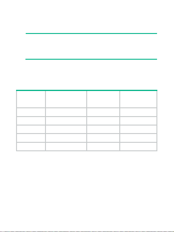
Table 1 Mounting options available for the switch
Switch
model
S8G-U Not supported Supported Supported
S9-PWR Not supported Supported Supported
S16G-U Supported Supported Not supported
S24-U Supported Supported Not supported
S24G-U Supported Supported Not supported
Rack mounting
Workbench
mounting
Wall
mounting
Mounting in a 19-inch rack
No mounting brackets and screws are provided with the switch.
Prepare them yourself.
To install the switch in a 19-inch rack:
1. Verify that the rack is reliably grounded and is stable.
2. Use screws to attach the mounting brackets to both sides of the
chassis.
2
Page 3
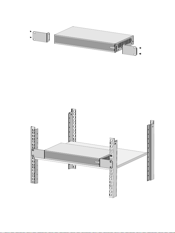
Figure 1 Attaching mounting brackets to the switch
3. Place the switch on a rack shelf in the rack. Push the switch in
until the oval holes in the brackets align with the mounting holes
in the front rack posts.
4. Use screws to secure the mounting brackets to the front rack
posts.
Figure 2 Mounting the switch in the rack
3
Page 4

NOTE:
Mounting brackets are used only for securing the switch to the
rack. A rack shelf on the rack is required to bear the switch
weight.
Mounting on a workbench
1. Verify that the workbench is clean, sturdy, and reliably
grounded.
2. Place the switch bottom up, and clean the four recessed areas
in the chassis bottom with a soft and dry cloth.
3. Attach the rubber feet to the recessed areas.
4. Place the switch upside up on the workbench.
Mounting on a wall
You can use pan-head screws and the mounting holes in the switch
bottom to mount the switch on a wall.
No screws and screw anchors are provided with the switch. Prepare
them yourself. The following figure shows the screw and screw
anchor of the recommended size.
4
Page 5
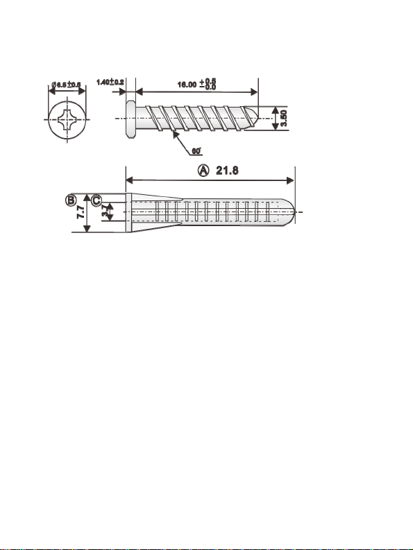
Figure 3 Screw and screw anchor of the recommended size
(mm)
To mount the switch on a wall:
1. Determine the hole diameter and depth based on the screw and
screw anchor size. Make sure the screw anchor can be inserted
into the hole and seated flush with the wall and the screw can be
fastened securely into the anchor.
If you use screws and screw anchors of the recommended size,
the hole diameter is 5 mm (0.20 in).
2. Drill two holes spacing 90 mm (3.54 in) on the wall. Make sure
the two holes are on a horizontal line.
3. Fasten a screw anchor into each hole and make sure the anchor
is flush with the wall.
4. Insert a screw into each anchor, leaving a minimum of 2.5 mm
(0.10 in) between the screw head and wall for mounting the
switch
5. Align the two mounting holes in the switch bottom with the
screws and hang the switch on the screws.
5
Page 6

Figure 4 Mounting the switch on a wall
Connecting cables
Connecting the grounding cable
CAUTION:
Correctly connecting the grounding cable is crucial to lightning
protection and EMI protection.
The switch is not provided with a grounding cable. Prepare one
yourself.
6
Page 7

To connect the grounding cable:
1. Use a Phillips screwdriver to remove the grounding screw from
grounding hole in the rear panel of the chassis. Use the
grounding screw to attach the ring terminal of the grounding
cable to the grounding hole. Fasten the grounding screw into the
grounding hole.
2. Use needle-nose pliers to make a loop at the other end of the
cable.
3. Remove the hex nut from a grounding post on the grounding
strip. Attach the loop to the grounding post and fasten the hex
nut.
Figure 5 Connecting the grounding cable
Connecting the power cord
Connecting the AC power cord
The S16G-U, S24-U, and S24G-U switches support AC power input.
To connect the AC power cord:
1. Make sure the switch is reliably grounded.
2. Connect one end of the AC power cord to the AC power
receptacle on the switch.
3. Connect the other end of the AC power cord to an AC power
source.
7
Page 8

Connecting a power adapter
The S8G-U and S9-PWR switches support power input by using a
power adapter.
To connect the power adapter:
1. Connect the power cord to the power adapter.
This step is not required for an S8G-U switch.
2. Connect the DC connector of the power adapter to the DC
power receptacle on the switch.
3. Connect the plug of the power adapter to an AC power source.
Figure 6 Connecting a power adapter
23
1
8
Page 9

Appendix A Chassis views and technical specifications
Chassis views
Front panel
Figure 7 S8G-U front panel
Figure 8 S9-PWR front panel
Figure 9 S16G-U front panel
9
Page 10

Figure 10 S24-U front panel
Figure 11 S24G-U front panel
7 8 12
(1) Power LED (Power)
(2) 10/100/1000Base-T copper port status LED
(3) Uplink port status LED
(4) 10/100Base-TX copper port status LED
(5) PoE status LED (6) PoE-MAX LED
(7) 10/100/1000Base-T copper port (8) DIP switch
(9) 10/100Base-TX copper port
10
Page 11

NOTE:
The three-position DIP switch can shift the switch functions as
follows:
• 标准交换—Enable flow control and downshift.
• 网络克隆—Disable flow control and enable downshift.
• 汇聚上联—Enable flow control, downshift, and uplink port
aggregation. (Ports 15 and 16 on the S16G-U and ports 23
and 24 on the S24G-U are uplink ports.)
Rear panel
Figure 12 S8G-U rear panel
Figure 13 S9-PWR rear panel
11
Page 12

Figure 14 S16G-U/S24-U/S24G-U rear panel
(1) Security slot (2) 10/100/1000Base-T copper port
(3) DC power receptacle (4) 10/100Base-TX copper port
(5) 100Base-TX copper port (uplink port)
(6) Grounding screw (7) AC power receptacle
Technical specifications
Table 2 Technical specifications (1)
Item S8G-U S9-PWR S16G-U
Dimensions
(H × W × D)
Weight
Port
27 × 158 ×
105 mm
(1.06 × 6.22
× 4.13 in)
≤ 0.4 kg
(0.88 lb)
8 × 10/100/
1000BaseT copper
port
27 × 235 ×
105 mm (1.06
× 9.25 × 4.13
in)
≤ 0.5 kg (1.10
lb)
8 ×
10/100Base-T
X copper port
1 ×
100Base-TX
copper port
(uplink port)
44 × 330 × 173
mm (1.73 ×
12.99 × 6.81
in)
≤ 1.4 kg (3.09
lb)
16 ×
10/100/1000
Base-T copper
port
12
Page 13

Item S8G-U S9-PWR S16G-U
Supported by
ports 1
PoE power
supply
Power
consumption
(static)
Power
consumption
(full
configuration)
Cooling
system
Input voltage
Port
specifications
Overall
leakage
current
Operating
temperature
Operating
relative
humidity
Not
supported
0.5 W 2 W 7.8 W
≤ 4 W ≤ 70 W ≤ 11 W
Natural cooling
DC: 12 V/0.5 A DC: 54 V/1.48
RJ-45 connector
Half/full duplex, auto-negotiation, MDI/MDI-X
GB4943.1
0°C to 40°C (32°F to 104°F)
5% RH to 95% RH, noncondensing
through 8.
A maximum
PoE power
capacity of 30
W per port
A
Not supported
AC: 100 VAC
to 240 VAC @
50 Hz or 60 Hz
13
Page 14

Item S8G-U S9-PWR S16G-U
Fire
resistance
GB4943.1
compliance
Table 3 Technical specifications (2)
Item S24-U S24G-U
Dimensions (H
× W × D)
44 × 330 × 173 mm
(1.73 × 12.99 × 6.81
in)
44 × 330 × 173 mm
(1.73 × 12.99 × 6.81
in)
Weight ≤ 1.5 kg (3.31 lb) ≤ 1.6 kg (3.53 lb)
Port
PoE power
supply
24 × 10/100Base-TX
copper port
Not supported Not supported
24 ×
10/100/1000Base-T
copper port
Power
consumption
3.7 W 7.8 W
(static)
Power
consumption
(full
≤ 9 W ≤ 16.5 W
configuration)
Cooling system Natural cooling
Input voltage AC: 100 VAC to 240 VAC @ 50 Hz or 60 Hz
Port
specifications
RJ-45 connector
Half/full duplex, auto-negotiation, MDI/MDI-X
14
Page 15

Item S24-U S24G-U
Overall
leakage current
Operating
temperature
Operating
relative
humidity
Fire resistance
compliance
GB4943.1
0°C to 40°C (32°F to 104°F)
5% RH to 95% RH, noncondensing
GB4943.1
Appendix B LEDs
LED Status Description
The switch is powered on and the
power module is operating
correctly.
The switch is not powered on or
the power module is faulty.
A 100-Mbps link is present.
The port is receiving or sending
data at 100 Mbps.
Power LED
(power)
Uplink port
status LED on
the S9-PWR
switch
Steady
green
Off
Steady
green
Flashing
green
Off No link is present.
15
Page 16

LED Status Description
10/100
Base-TX
copper port
status LED
(Link/Act)
10/100/1000B
ase-T copper
port status
LED
(Link/Act)
PoE-MAX
LED on the
S9-PWR
switch
PoE status
LED on the
S9-PWR
switch
Steady
green
Flashing
green
Off No link is present.
Steady
green
Flashing
green
Steady
yellow
Flashing
yellow
Off No link is present.
Steady
yellow
Off
Steady
yellow
Flashing
yellow
Off No PoE power supply.
A 10/100-Mbps link is present.
The port is receiving or sending
data at 10/100 Mbps.
A 1000-Mbps link is present.
The port is receiving or sending
data at 1000 Mbps.
A 10/100-Mbps link is present.
The port is receiving or sending
data at 10/100 Mbps.
The switch PoE power is in the
protection range 58 W to 64 W.
The switch PoE power does not
reach the protection range
Normal PoE power supply.
Abnormal PoE power supply.
16
Page 17

© 2017 New H3C Technologies Co., Ltd.
Website: http://www.h3c.com.hk
E-mail: service@h3c.com
17
 Loading...