

Page 1

Hangzhou H3C Technologies Co., Ltd.
http://www.h3c.com
Document version: 5PW101-20110308
H3C Access Controller Modules
Software Upgrade Guide
Page 2

Copyright © 2009-2011, Hangzhou H3C Technologies Co., Ltd. and its licensors
All rights reserved
No part of this manual may be reproduced or transmitted in any form or by any means without prior
written consent of Hangzhou H3C Technologies Co., Ltd.
Trademarks
Notice
H3C,
, Aolynk, , H3Care,
SecPro, SecPoint, SecEngine, SecPath, Comware, Secware, Storware, NQA, VVG, V
, TOP G, , IRF, NetPilot, Neocean, NeoVTL,
2
G, VnG, PSPT,
XGbus, N-Bus, TiGem, InnoVision and HUASAN are trademarks of Hangzhou H3C Technologies Co.,
Ltd.
All other trademarks that may be mentioned in this manual are the property of their respective owners
The information in this document is subject to change without notice. Every effort has been made in the
preparation of this document to ensure accuracy of the contents, but all statements, information, and
recommendations in this document do not constitute the warranty of any kind, express or implied.
Page 3

Preface
The H3C Access Controller Modules Software Upgrade Guide describes how to upgrade various types
of access controller modules through the web interface or at the command line interface (CLI).
The Appendix describes how to upgrade the software of access controller modules at the BootWare
menu.
This preface includes:
•
Audience
Conventions
•
Obtaining documentation
•
Technical support
•
Documentation feedback
•
Audience
This documentation is intended for:
• Network planners
• Field technical support and servicing engineers
• Network administrators working with the access controller modules
Conventions
This section describes the conventions used in this guide.
Command conventions
Convention Description
Boldface Bold text represents commands and keywords that you enter literally as shown.
Italic Italic text represents arguments that you replace with actual values.
[ ] Square brackets enclose syntax choices (keywords or arguments) that are optional.
{ x | y | ... }
[ x | y | ... ]
{ x | y | ... } *
[ x | y | ... ] *
Braces enclose a set of required syntax choices separated by vertical bars, from which
you select one.
Square brackets enclose a set of optional syntax choices separated by vertical bars, from
which you select one or none.
Asterisk marked braces enclose a set of required syntax choices separated by vertical
bars, from which you select at least one.
Asterisk marked square brackets enclose optional syntax choices separated by vertical
bars, from which you select one choice, multiple choices, or none.
&<1-n>
The argument or keyword and argument combination before the ampersand (&) sign can
be entered 1 to n times.
Page 4

Convention Description
# A line that starts with a pound (#) sign is comments.
GUI conventions
Convention Description
Symbols
Boldface
> Multi-level menus are separated by angle brackets. For example, File > Create > Folder.
Window names, button names, field names, and menu items are in Boldface. For
example, the New User window appears; click OK.
Convention Description
< > Button names are inside angle brackets. For example, click <OK>.
[ ]
/ Multi-level menus are separated by forward slashes. For example, [File/Create/Folder].
Window names, menu items, data table and field names are inside square brackets. For
example, pop up the [New User] window.
Convention Description
WARNING
CAUTION
IMPORTANT
NOTE
An alert that calls attention to important information that if not understood or followed can
result in personal injury.
An alert that calls attention to important information that if not understood or followed can
result in data loss, data corruption, or damage to hardware or software.
An alert that calls attention to essential information.
An alert that contains additional or supplementary information.
TIP
An alert that provides helpful information.
Obtaining documentation
You can access the most up-to-date H3C product documentation on the World Wide Web at
http://www.h3c.com.
Click the links on the top navigation bar to obtain different categories of product documentation:
[Technical Support & Documents > Technical Documents]—Provides hardware installation, software
upgrading, and software feature configuration and maintenance documentation.
[Products & Solutions]—Provides information about products and technologies, as well as solutions.
[Technical Support & Documents > Software Download]—Provides the documentation released with the
software version.
Technical support
customer_service@h3c.com
http://www.h3c.com
Page 5

Documentation feedback
You can e-mail your comments about product documentation to info@h3c.com.
We appreciate your comments.
Page 6

Contents
Access controller module overview·····························································································································1
Software upgrade methods ········································································································································· 2
Software upgrade through the web interface············································································································ 3
Setting up a web-based configuration environment ······································································································3
Configuring software upgrade ········································································································································6
Software upgrade at the CLI ······································································································································· 9
Preparations·······································································································································································9
Setting up a configuration environment ·················································································································9
Connecting the console cable······························································································································ 10
Setting terminal parameters·································································································································· 10
Logging in to the access controller module ········································································································ 13
Software upgrade through FTP at the CLI···················································································································· 14
Using the access controller module as the FTP server ······················································································· 14
Using the access controller module as the FTP client························································································· 16
Upgrade through TFTP at the CLI·································································································································· 17
Maintaining application and configuration files at the CLI·····················································································19
Displaying all files at the CLI································································································································ 19
Setting the application file type at the CLI ·········································································································· 19
Deleting a File at the CLI ······································································································································19
Backing up and restoring the BootWare at the CLI·································································································20
Backing up the BootWare ···································································································································· 20
Restoring the BootWare········································································································································ 20
Appendix Introduction to software maintenance·····································································································21
BootWare program file ········································································································································ 21
Application files····················································································································································· 21
Configuration files ················································································································································· 22
Appendix Upgrading software through the BootWare menu·················································································23
Preparations···································································································································································· 23
Introduction to the BootWare menu ····························································································································· 23
Main menu ····························································································································································· 23
Serial submenu ······················································································································································ 24
Ethernet submenu ··················································································································································25
File control submenu ············································································································································· 25
BootWare operation submenu····························································································································· 25
Storage device operation submenu····················································································································· 26
Upgrading BootWare through the management Ethernet port ················································································· 26
Upgrading an application program through TFTP in BootWare menu···································································· 28
Upgrading an application program through FTP in BootWare menu······································································ 30
Upgrading BootWare and applications through a serial port·················································································· 32
XMODEM overview ·············································································································································· 32
Modifying serial port parameters ························································································································ 32
Upgrading the BootWare program····················································································································· 34
Upgrading applications········································································································································ 37
Appendix Maintaining application and configuration files at the BootWare menu·············································38
Displaying all files at the BootWare menu·················································································································· 38
i
Page 7

Setting the application file type at the BootWare menu ···························································································· 38
Deleting a file at the BootWare menu ························································································································· 39
Appendix Dealing with password loss·····················································································································40
User password loss ························································································································································ 40
BootWare password loss ·············································································································································· 40
Super password loss······················································································································································ 41
Appendix Backing up and restoring BootWare······································································································42
Index ···········································································································································································43
ii
Page 8

Access controller module overview
Access controller modules are access controller products independently developed by Hangzhou H3C
Technologies Co., Ltd (hereinafter referred to as H3C). H3C access controller modules feature optional
capacities, high reliability, and abundant service types. Adapted to various H3C network products, such
as Fit APs, the access controller modules can be used in most wireless applications. Targeting the wireless
local area network (WLAN) access of enterprise networks and metropolitan area networks (MANs),
H3C access controller modules are ideal access controllers for such application scenarios as WLAN
access of large-sized, medium-sized, and small-sized enterprise campuses, wireless MAN coverage, and
hot spot coverage.
Table 1 Types of access controller modules
Model
LSQM1WCMB0 Yes Yes CF card
LSQM1WCMD0 Yes Yes CF card
LSBM1WCM2A0 Yes Yes CF card
LSRM1WCM2A1 Yes Yes CF card
LSRM1WCM3A1 Yes Yes CF card
LSWM1WCM10 No Yes CF card
LSWM1WCM20 No Yes Flash
Serial port
(Console port)
Management
Ethernet port
Storage
medium
Applicable to…
S7502E/S7503E/S7503ES/S7506E/S7506E-S/S75
06E-V/S7510E Ethernet
switch
S7502E/S7503E/S7503ES/S7506E-V/S7506E/S75
06E-S/S7510E Ethernet
switch
S9512/S9508/S9508V/S
9505 Ethernet switch
S9505E/S9508E/S9508EV/S9512E Ethernet switch
S9505E/S9508E/S9508EV/S9512E Ethernet switch
S5800-60C-PWR/S5820X28C Ethernet switch
S5800-60C-PWR/S5800-3
2F/S5800-56C/S5800-32
C/S5800-32C-PWR/S580
0-56C-PWR Ethernet switch
EWPX1WCMD0 Yes Yes CF card WX6103 access controller
1
Page 9

Software upgrade methods
You can upgrade the software of the access control modules through the web interface or at the
command line interface (CLI).
NOTE:
• If you boot an access controller module and the prompt Press Ctrl+B to enter extend boot menu...
appears, you can press Ctrl+B to enter the BootWare menu and upgrade the software of the module.
• Only a technical engineer can upgrade the software of the module at the BootWare menu.
• For more information about software upgrade at the BootWare menu, see “
Appendix Upgrading
software through the BootWare menu.”
If multiple application files exist in the storage medium, use the boot-loader file file-url { main | backup }
command to specify a boot file to be used for next boot of the device. In the command,
• file file-url: Name of the boot file, consisting of 1 to 64 characters.
• main: Main application file.
• backup: Backup application file.
The main application file is used to boot the device. The backup application file is used to boot and start
the device when the main application file is unavailable. For detailed configuration, see “
application file type at the CLI.”
CAUTION:
Because access controller modules must work with Fit APs, you need to load Fit AP application
Setting the
files and
licenses to access controller modules. For information about how to load the files, see “Software upgrade
through the web interface” and “
Software upgrade at the CLI.”
2
Page 10
t
Software upgrade through the web interface
NOTE:
• This chapter takes software upgrade of access controller module LSQM1WCMB0 on an S7500E switch
and LSWM1WCM20 on an S5800 switch as examples. Unless otherwise specified, the software
upgrade procedures of all access controller modules are the same.
• You can log in to an access controller module through the console port of the module or redirect to the
module from a switch. If an access controller module does not have a console port, you can only redirec
to it from a switch.
• The display of web interface varies with device models.
The web-based network management function allows an administrator to conveniently manage and
maintain network devices through the web interface.
Setting up a web-based configuration environment
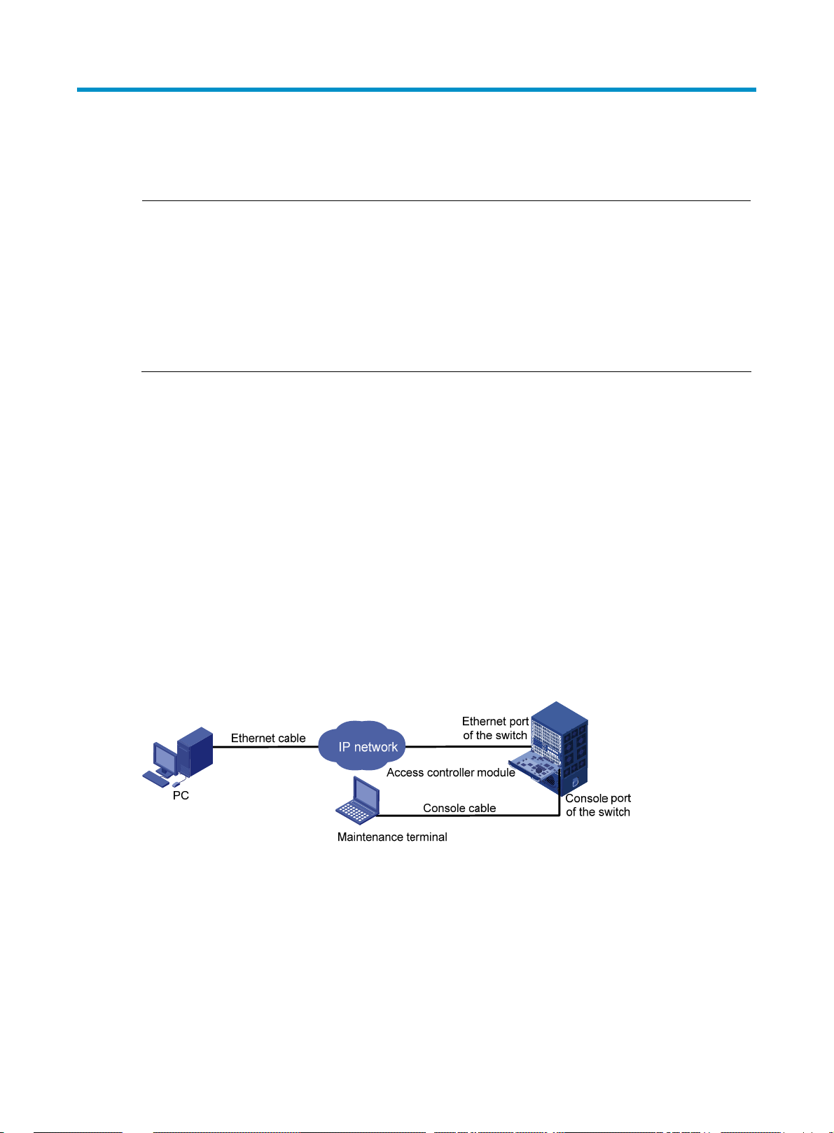
1. Set up a web-based network management environment as shown in Figure 1.
Set up the web-based configuration environment by using one of the following two network connection
methods:
• Co nnect the E th ern et port of th e switch to the PC wi th an Ethernet cable and ensure that a route from
the PC to the access controller module is active.
• Connect t he ma nage ment Ethe rnet p ort of t he ac cess cont ro ller modu le to the PC an d ens ure a ro ute
from the PC to the access controller module is active.
As these two upgrade methods are similar, this document describes only the first method.
Figure 1 Set up a web-based configuration environment
2. Configure the switch
• Configuration on an S7500E switch with access controller module LSQM1WCMB0
# Configure interface Ten-GigabitEthernet 2/0/1 that connects the switch and LSQM1WCMB0 as a
trunk port and to permit all VLANs. In this example, LSQM1WCMB0 is inserted in slot 2.
[S7500]interface ten-gigabitethernet2/0/1
[S7500-Ten-GigabitEthernet2/0/1]port link-type trunk
[S7500-Ten-GigabitEthernet2/0/1]port trunk permit vlan all
[S7500]quit
3
Page 11

• Configuration on an S5800 switch with access controller module LSWM1WCM20
# Create Layer 2 aggregate interface Bridge-Aggregation 1.
<S5800>system-view
[S5800]interface Bridge-Aggregation 1
[S5800-Bridge-Aggregation1]quit
# Add interfaces GigabitEthernet 1/1/1 and GigabitEthernet 1/1/2 that connect the switch and
LSWM1WCM20 to Bridge-Aggregation 1.
[S5800]interface GigabitEthernet 1/1/1
[S5800-GigabitEthernet1/1/1]port link-aggregation group 1
[S5800-GigabitEthernet1/1/1]quit
[S5800]interface GigabitEthernet 1/1/2
[S5800-GigabitEthernet1/1/2]port link-aggregation group 1
[S5800-GigabitEthernet1/1/2]quit
# Configure aggregate interface Bridge-Aggregation 1 as a trunk port and to permit all VLANs.
[S5800]interface Bridge-Aggregation 1
[S5800-Bridge-Aggregation1]port link-type trunk
[S5800-Bridge-Aggregation1]port trunk permit vlan all
[S5800]quit
3. Configure the access control module
CAUTION:
Before you redirect to an access controller module from the switch, make sure the AUX port on the access
controller module is in none authentication mode, which is the factory defaults. For how to configure an
AUX port in none authentication mode, see Table 3.
• Configuration for the access controller module LSQM1WCMB0 on an S7500E switch
# Redirect to LSQM1WCMB0 from the switch. In this example, LSQM1WCMB0 is inserted in slot 2.
<S7500>oap connect slot 2
Press CTRL+K to quit.
Connected to OAP!
<H3C>
# Configure interface Ten-GigabitEthernet 1/0/1 that connects LSQM1WCMB0 and the switch as a
trunk port and to permit all VLANs.
<H3C>system-view
[H3C]interface ten-gigabitEthernet 1/0/1
[H3C-Ten-GigabitEthernet1/0/1]port link-type trunk
[H3C-Ten-GigabitEthernet1/0/1]port trunk permit vlan all
[H3C]quit
• Configuration for the access controller module LSWM1WCM20 on an S5800 switch
# Redirect to LSWM1WCM20 from the switch.
<S5800>oap connect slot 1 system SubSlot1
Press CTRL+K to quit.
Connected to SubSlot1!
<H3C>
# Create Layer 2 aggregate interface Bridge-Aggregation 1.
<H3C>system-view
4
Page 12

g
System View: return to User View with Ctrl+Z.
[H3C]interface Bridge-Aggregation 1
[H3C-Bridge-Aggregation1]quit
# Add interfaces GigabitEthernet 1/0/1 and GigabitEthernet 1/0/2 that connect the switch and
LSWM1WCM20 to aggregate interface Bridge-Aggregation 1.
[H3C]interface GigabitEthernet 1/0/1
[H3C-GigabitEthernet1/0/1]port link-aggregation group 1
[H3C-GigabitEthernet1/0/1]quit
[H3C]interface GigabitEthernet 1/0/2
[H3C-GigabitEthernet1/0/2]port link-aggregation group 1
[H3C-GigabitEthernet1/0/2]quit
# Configure aggregate interface Bridge-Aggregation 1 as a trunk port and to permit all VLANs.
[H3C]interface Bridge-Aggregation 1
[H3C-Bridge-Aggregation1]port link-type trunk
[H3C-Bridge-Aggregation1]port trunk permit vlan all
[H3C]quit
# Configure the IP address of VLAN-interface 1 of the access controller module as 192.168.0.100/24.
<H3C> system-view
[H3C] interface Vlan-interface 1
[H3C-Vlan-interface1] ip address 192.168.0.100 24
[H3C-Vlan-interface1] quit
# Configure the web username as admin, password as admin, and user level as 3, namely, administrator
level.
[H3C] local-user admin
[H3C-luser-admin] service-type telnet
[H3C-luser-admin] authorization-attribute level 3
[H3C-luser-admin] password simple admin
[H3C-luser-admin] quit
NOTE:
The device carries default web lo
in information when delivered. You can use the default information to
log in to the web interface. The default web login information includes username admin, password
admin, and the IP address 192.168.0.100/24 of VLAN-interface 1 of the access controller module.
4. Configure an IP address, such as 192.168.0.200/24, for the PC so that the PC can communicate
with the access controller module.
5. On the web-based network management terminal (the PC), start the browser. In the address box of
the browser, type http://192.168.0.100 and press Enter (check that a route active between the
PC and access controller module). The browser displays the login authentication page of
web-based network management, as shown in
Figure 2. Enter username admin, password admin
and the verification code, select a language (Chinese or English), and then click Login.
5
Page 13
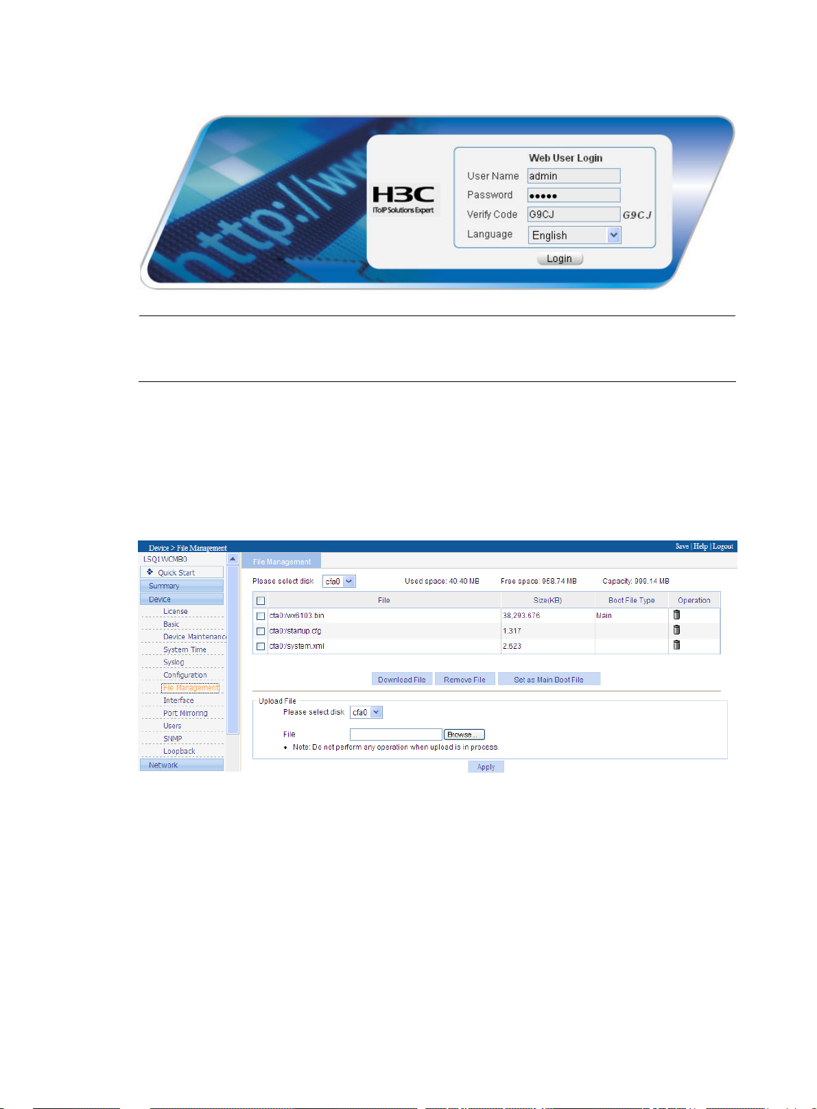
Figure 2 Web user login interface
NOTE:
Web-based network management supports the following browsers: Microsoft Internet Explorer 6.0 SP2,
Mozilla Firefox 3.0, Google Chrome 2.0.174.0, and their later versions.
Configuring software upgrade
1. After logging in to the web interface, select Device > File Management from the navigation tree to
view the free space of the disk. If the free space is not big enough, remove useless files, as shown
in
Figure 3.
Figure 3 File management interface
2. Select Device > Device Maintenance from the navigation tree to enter the software upgrade
configuration page, as shown in
Figure 4.
6
Page 14
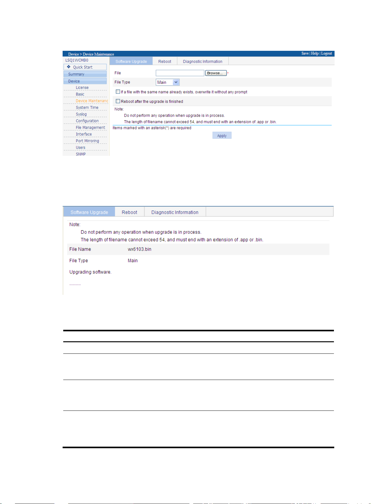
Figure 4 Software upgrade interface
3. Click Browse to locate the local upgrade files. After specifying the file type, you can select the
options If a file with the same name already exists, overwrite it without any prompts and Reboot
after the upgrade is finished. Click Apply.
Figure 5 Software upgrade in progress
Table 2 lists the detailed software upgrade configuration items.
Table 2 Detailed software upgrade configuration items
Item Description
File Browses for a local application program which has the extension .bin.
Sets the file name of the application program after it is uploaded to the
Filename
File Type
If a file with the same name already
exists, overwrite it without any
prompt.
device. The file name must have an extension the same as that of the
application program to be uploaded.
Sets the file boot type.
Main: Main boot file for the next boot.
Backup: Backup boot file for the next boot.
Specifies whether to overwrite a file with the same name.
If this option is not selected, when a file with the same name exists on the
device, the File already exists prompt is displayed and the upgrade
cannot begin.
7
Page 15

Item Description
Reboot after the upgrade is
finished.
CAUTION:
Specifies whether to reboot the device so that the software upgrade takes
effect when the file is uploaded successfully.
Software upgrade may take a while. Do not perform any operations on the web interface when software
is being upgraded. Otherwise, the software upgrade is interrupted.
8
Page 16

Software upgrade at the CLI
After the Access controller module is normally started, you can upgrade, backup and restore the software
and configure files at the CLI.
NOTE:
• This chapter takes software upgrade of access controller module LSQM1WCMB0 on an S7500E switch
for example. Unless otherwise specified, the software upgrade procedures of all access controller
modules are the same.
• Access controller modules LSWM1WCM10 and LSWM1WCM20 do not have console ports.
not support operations requiring the connection to the console port.
• The display of CLIs varies with device models.
Preparations
Before the upgrade, complete the following preparations:
Setting up a configuration environment
Set up the configuration environment by using one of the following two network connection methods:
Method 1:
Set up a configuration environment by connecting the console port of the access controller module to a
console terminal, a PC in this example, as shown in
Figure 6 Connect the PC to the console port of the access controller module
Figure 6.
They do
Method 2:
Connect a terminal (a PC in this example) to the console port of the switch through a console cable. See
Figure 7. Then, log in to the access controller module from the switch through redirection. For the
configuration method, see “
Figure 7 Connect the PC to the console port of the switch
Redirecting to the access controller module from the switch.”
9
Page 17

Connecting the console cable
Step1 Connect the DB-9 female connector of the console cable to the serial port of the PC.
Step2 Connect the RJ-45 connector of the console cable to the console port of the access controller module or
the switch.
Setting terminal parameters
Step 1: Launch a terminal emulation program on a PC, for example, Terminal under Windows 3.1 and
HyperTerminal under Windows 95/98/NT/2000/XP.
Step 2: Set the parameters for the console terminal as follows:
• Bits per second: 9600
• Data bits: 8
• Parity: none
• Stop bits: 1
• Flow control: none
• Terminal emulation: VT100
Follow these steps to set the parameters:
1. On the PC, select Start > All Programs > Accessories > Communications > HyperTerminal. The
Connection Description dialog box appears.
Figure 8 Set up a new connection
2. Type a name, test in this example, for the new connection in the Name field and click OK. The
Connect To dialog box appears.
10
Page 18

Figure 9 Connect To dialog box
3. Select a serial port from the Connect using drop-down list. Be sure to select the serial port to which
the console cable is actually connected. Then click OK.
Figure 10 Set serial port parameters
NOTE:
To use the default settings, click Restore Defaults.
4. Click OK. The HyperTerminal window appears, as shown below.
11
Page 19

Figure 11 HyperTerminal window
5. Set HyperTerminal properties. In the HyperTerminal window, choose File > Properties from the
menu, and select the Settings tab to enter the properties setting dialog box, as shown below. Select
VT100 or Auto detect from the Emulation drop-down list, and click OK to return to the
HyperTerminal window.
Figure 12 Set the emulation type
12
Page 20

Logging in to the access controller module
NOTE:
Because the LSWM1WCM10 and LSWM1WCM20 do not have console ports, you can only redirect to
them from switches.
Logging in to the access controller module directly
When the first connection method described in “Setting up a configuration environment” is used, the
serial port of the PC is connected to the console port of the access controller module and you can directly
log in to the access controller module through the HyperTerminal on the PC.
Redirecting to the access controller module from the switch
Before you redi rect to an acc ess controller module from the switch, make sure the AUX port on the ac cess
controller module is in none authentication mode, which is the factory defaults. For how to configure an
AUX port in none authentication mode, see
Table 3 Configure the AUX port in none authentication mode
To do… Use the command… Remarks
Enter AUX port user interface view
Configure the AUX port in none
authentication mode
user-interface aux first-number
[ last-number ]
authentication-mode none
Table 3.
—
Optional
By default, the authentication
mode for an AUX port is none.
Set the command level for the user
to access
user privilege level level
Optional
Level 3 by default.
When the second connection method described in “Setting up a configuration environment” is used, the
serial port of the PC is connected to the console port of the switch. After logging in to the switch through
the HyperTerminal, you can redirect to the access controller module from the switch by performing the
following operations.
After you redirect to the operating system of the access controller module from the switch, the displayed
interface is switched from the CLI of the switch to the operation interface of the access controller module,
so that you can manage the access controller module.
After the interface switchover, you can return to the CLI of the switch by pressing Ctrl+K.
Table 4 Redirect to the access controller module from the switch
To do… Use the command… Remarks
Redirect to the access controller
module from an S7500E switch
Redirect to the access controller
module from an S5800 switch
oap connect slot slot-number
oap connect slot slot-number system
system-name
Required
Available in user view of the
switch
Required
Available in user view of the
switch
13
Page 21

Examples:
# Redirect to the access controller module in slot 2 from the S7500E switch.
<S7500> oap connect slot 2
Connected to OAP!
<H3C>
# Redirect to the access controller module in slot 1 from the S5800 switch.
<S5800> oap connect slot 1 system SubSlot1
Press CTRL+K to quit.
Connected to SubSlot1!
<H3C>
Software upgrade through FTP at the CLI
Using the access controller module as the FTP server
The File Transfer Protocol (FTP) is an application layer protocol in the TCP/IP suite. It is mainly used for
file transfer between remote hosts. FTP provides a reliable, connection-oriented data transfer service over
TCP.
With the access controller module as the FTP server, you can run the FTP client application on a PC and
log in to the access controller module for file operations.
Before using FTP, you need to install the FTP client application on your PC. The FTP client software is not
provided with the access controller module. You need to make sure that it is available by yourself. The
description here assumes that you are using the FTP client application of Microsoft Windows XP.
1. Set up a network environment, as shown below:
Figure 13 Set up a software maintenance environment (access controller module as FTP server)
Configure the IP addresses for both sides, which must be on the same subnet. For example, set the IP
address of the FTP client to 192.168.0.1, and that of the access controller module’s management Ethernet
port to 192.168.0.100. Use ping to verify the network connectivity.
2. Enable FTP service.
You can enable FTP service after configuring FTP server authentication and authorization. Use the
following command to enable FTP service.
[H3C] ftp server enable
Add an authorized FTP username and password.
[H3C] local-user guest Create user account guest
[H3C-luser-guest] service-type ftp Set user type to FTP
[H3C-luser-guest] password simple 123456 Set password 123456 for user guest
[H3C-luser-guest] authorization-attribute level 3 Set the local user level to 3
14
Page 22

3. Connect the PC to the FTP server
After enabling the FTP service and configuring the username and password, you can enable FTP client
on the PC. In the following example, the FTP client application program is the built-in Windows XP FTP
client.
Type ftp in the DOS window:
C:\Documents and Settings\Administrator>ftp
ftp> The system prompt changed to ftp>
ftp> open 192.168.0.100 IP address of the access controller module
Connected to 192.168.0.100.
220 FTP service ready.
User (192.168.0.100:(none)): guest Username configured on the access controller
module
331 Password required for guest
Password: Enter the password 123456
230 User logged in Successfully connected to the server
4. Upgrade application files.
ftp> put main.bin main.bin Upload the upgrade file to the access controller
module
200 Port command okay.
150 Opening BINARY mode data connection for /main.bin.
226 Transfer complete.
ftp: 22554232 bytes sent in 82.25Seconds 274.22Kbytes/sec...
ftp> quit Quit FTP
221 Server closing
5. Back up application files and configuration files.
Use the following commands to maintain the access controller module. In this example, the file main.bin
on the access controller module is copied to the PC.
ftp> binary Set the transfer mode to binary
200 Type set to I.
ftp> lcd c:\temp Change the local path
Local directory now C:\temp.
ftp> get main.bin main.bin Backup to PC
200 Port command okay.
150 Opening BINARY mode data connection for /main.bin.
226 Transfer complete.
ftp: 22554232 bytes received in 21.52Seconds 1048.25Kbytes/sec.
6. Restore backup application files and configuration files.
To restore the backup files to the access controller module, do the following:
ftp> put main.bin main.bin Restore file to access controller module
200 Port command okay.
150 Opening BINARY mode data connection for /main.bin.
226 Transfer complete.
ftp: 22554232 bytes sent in 82.25Seconds 274.22Kbytes/sec.
ftp> quit Quit FTP
221 Server closing
15
Page 23

Using the access controller module as the FTP client
You can also maintain the file system of the access controller module by setting up a software
maintenance environment where the access controller module serves as a client.
1. Set up a maintenance environment.
Figure 14 Set up a software maintenance environment in CLI mode (access controller module as FTP
client)
Run the FTP server program on the PC, set the file path, and set the username and password for the
access controller module.
Configure the IP addresses for both sides, which must be on the same subnet. For example, set the IP
address of the FTP server to 192.168.0.1, and that of the LSRM1WCM2A1 access controller module’s
management Ethernet port to 192.168.0.100. Use ping to verify the network connectivity.
2. Connect to the FTP server.
Log in to the FTP server through the console terminal connected with the access controller module.
<H3C> ftp 192.168.0.1
Trying 192.168.0.1 ...
Press CTRL+K to abort
Connected to 192.168.0.1.
220 3Com 3CDaemon FTP Server Version 2.0
User(192.168.0.1:(none)):guest Enter the username configured on the FTP
server.
331 User name ok, need password
Password: Enter the corresponding password.
230 User logged in The connection is established.
[ftp]
3. Upgrade application files.
[ftp] get main.bin main.bin Download the file from the FTP server
to the access controller module
cfa0:/main.bin has been existing. Overwrite it?[Y/N]:y
227 Entering passive mode (192,168,0,1,4,89)
125 Using existing data connection
226 Closing data connection; File transfer successful.
FTP: 22554232 byte(s) received in 26.563 second(s), 849.00K byte(s)/sec.
• Back up application files and configuration files.
Use the put command to back up files after logging in.
[ftp]binary Set transmission mode to binary
200 Type set to I.
[ftp] put main.bin main.bin Back up files to the FTP server
16
Page 24

227 Entering passive mode (192,168,0,1,4,91)
125 Using existing data connection
226 Closing data connection; File transfer successful.
FTP: 22554232 byte(s) sent in 26.528 second(s), 850.00Kbyte(s)/sec.
[ftp] quit Quit FTP
221 Service closing control connection
4. Restore the backup application files and configuration files.
Use the get command to restore backup files.
[ftp] get main.bin main.bin Download the file main.bin from the
server to the access controller module
cfa0:/main.bin has been existing. Overwrite it?[Y/N]:y
227 Entering passive mode (192,168,0,1,4,89)
125 Using existing data connection
226 Closing data connection; File transfer successful.
FTP: 22554232 byte(s) received in 26.563 second(s), 849.00K byte(s)/sec
Upgrade through TFTP at the CLI
The Trivial File Transfer Protocol (TFTP) is a TCP/IP protocol used for file transfer between client and server.
It provides a simple and low-overhead file transfer service. TFTP provides unreliable data transfer over
UDP and does not provide any access authorization or authentication mechanism. It employs the timeout
retransmission method to implement best-effort delivery of data. Compared with FTP, TFTP has a much
smaller software size.
Using the Access controller module as the TFTP client and a file server as the TFTP server, you can use
commands on the console terminal, which can be the same file server, to upload configuration and
application files from the access controller module to the file server or download the files from the file
server to the access controller module.
1. Set up a configuration environment.
Figure 15 Set up an environment for software maintenance through the CLI (access controller module as
TFTP client)
Configure the IP addresses for both sides, which must be on the same subnet. For example, set the IP
address of the TFTP server to 192.168.0.1 and that of the management Ethernet port of the access
controller module to 192.168.0.100. Then use ping to verify the network connectivity.
2. Upgrade application programs.
After setting up the environment, perform the following operations on the console terminal.
Display the files in the current file system with the dir command.
<H3C> dir
Directory of cfa0:/
17
Page 25

g
0 -rw- 22554232 Mar 20 2009 09:09:42 main.bin
1 -rw- 987 Mar 19 2009 14:15:04 startup.cfg
2 -rw- 177 Mar 19 2009 14:15:04 system.xml
252164 KB total (230130 KB free)
File system type of cfa0: FAT32
<H3C>
Through TFTP, you can download an application file from the server to the access controller module and
overwrite the original main application file to upgrade the application program. The upgraded
application file takes effect after reboot.
# Download application file main.bin from the TFTP server to the device.
<H3C> tftp 192.168.0.1 get main.bin main.bin
The file main.bin exists. Overwrite it? [Y/N]:y
Verifying server file...
Deleting the old file, please wait...
File will be transferred in binary mode
Downloading file from remote TFTP server, please wait...|
TFTP: 22554232 bytes received in 38 second(s)
File downloaded successfully.
NOTE:
• If a file with the same name already exists on the access controller module, the system will ask you
whether to replace the existing file. Enter Y to replace it, or N to abort.
• You can upgrade a configuration file in the way you upgrade an application file. The backup
configuration file can be modified
with a text editor. You can modify the configurations by downloadin
the modified configuration file, and the modification takes effect after reboot.
3. Backing up an application file.
Using TFTP, you can back up an application file by uploading it from the access controller module to the
server.
# Upload file main.bin on from the access controller module to the server, and save it as main.bin.
<H3C> tftp 192.168.0.1 put main.bin main.bin
File will be transferred in binary mode
Sending file to remote TFTP server. Please wait...
TFTP: 22554232 bytes sent in 29 second(s).
File uploaded successfully.
NOTE:
• When you back up a file to the server and if a file with the same name already exists on the server, the
existing file will be replaced.
• You can back up a configuration file in the way you back up an application file.
18
Page 26

Maintaining application and configuration files at the CLI
Displaying all files at the CLI
View the files in the current file system with the dir command.
<H3C> dir
Directory of cfa0:/
0 -rw- 22554232 Mar 20 2009 09:56:54 main.bin
1 -rw- 987 Mar 20 2009 09:20:50 startup.cfg
2 -rw- 177 Mar 19 2009 14:15:04 system.xml
252164 KB total (230130 KB free)
File system type of cfa0: FAT32
<H3C>
Setting the application file type at the CLI
• To set type of main.bin to main, use the following command:
<H3C> boot-loader file main.bin main
This command will be set the boot file.Continue?[Y/N]:y
The specified file will be used as the main boot file at the next reboot on slot 1!
• To set type of main.bin to backup, use the following command:
<H3C> boot-loader file main.bin backup
This command will be set the boot file.Continue?[Y/N]:y
The specified file will be used as the backup boot file at the next reboot on slot 1!
Deleting a File at the CLI
To delete startup.cfg, use the following command:
<H3C> delete /unreserved startup.cfg
The contents cannot be restored!!! Delete cfa0:/startup.cfg?[Y/N]:y
%Delete file cfa0:/startup.cfg...Done
19
Page 27

Backing up and restoring the BootWare at the CLI
You can use the bootrom command to back up and restore the BootWare program.
Backing up the BootWare
<H3C> bootrom backup all
Now backuping bootrom, please wait...
Backup bootrom completed!
The entire BootWare has been copied to the access controller module.
<H3C> bootrom backup part
Now backuping bootrom, please wait...
Backup bootrom completed!
The extended BootWare has been copied to the access controller module.
Restoring the BootWare
<H3C> bootrom restore all
This command will restore bootrom file, Continue? [Y/N]:y
Now restoring bootrom, please wait...
Restore bootrom completed!
The backup entire BootWare has been restored to the system.
<H3C> bootrom restore part
This command will restore bootrom file, Continue? [Y/N]:y
Now restoring bootrom, please wait...
Restore bootrom completed!
The backup extended BootWare has been restored to the system.
20
Page 28

y
Appendix Introduction to software maintenance
NOTE:
Storage media include CF cards and Flash. Support for the storage media and file storage locations var
with access controller modules. For more information, see Table 1.
The access controller module manages the following three types of files:
• BootWare program file
• Application files
• Configuration files
BootWare program file
The BootWare program file is used by the access controller module to load the application program. The
whole BootWare program file consists of basic BootWare and extended BootWare.
• The basic BootWare implements system initialization.
• Extended BootWare provides abundant man-machine interaction functions. It is used for interface
initialization for application program and boot system upgrade.
• The whole BootWare refers to the combination of the two sections. After the basic BootWare is
started, you can load or upgrade the extended BootWare.
Application files
The access controller module supports the Dual Image function. By default, three application files are
defined for system boot:
• Main application file (main file)
• Backup application file (backup file)
• Secure application file (secure file)
These files are stored in the built-in CF card or Flash, with an extension name of .bin.
Typically, the default application file is written into the built-in CF card before the access controller
module is delivered. An access controller module with no CF card stores the default application file in its
Flash.
If you have loaded the three application files into the CF card or Flash, the system will use one of these
three files to boot in the order described below. For how to set the application file types, see “
application file type at the BootWare menu.”
The default names and types of the application files and their loading sequence are as follows:
• Main application file. The default name is main.bin, and the file type is M. It is the default
application file to be loaded when the system starts.
21
Setting the
Page 29

g
g
y
g
• Backup application file. The default name is backup.bin, and the file type is B. Upon failure of
loading the main application file, the system tries to load the backup file.
• Secure application file. The default name is secure.bin, and the file type is S. If the system fails to
load the backup application file, the secure application file is the last choice. If it again fails to load
the secure application file, the system will give a boot failure message.
Note that:
• Only the application files of the M, B, and S types can be used to boot the system, while an
application file of the N type (an application file other than the M, B, or S type) cannot.
• After the application program is loaded, you can rename the application files through the
command line interface (CLI) or change the types of the M, B and N application files through the
BootWare menu or the CLI. However, you cannot change the type of the S application file.
• As the S application file is the last choice for booting the system, you cannot change its type or
obtain it by changing the type of another type of application file. You can only download it using
the BootWare menu.
• Only one file of the same type (M, B, or S) can exist in the CF card or Flash. For example, if an
application file of type M+B exists in the CF card of LSRM1WCM2A1, another file of type M or B
cannot exist. If the type of another file is changed to B, the existing type M+B file changes to a file
of type M.
Configuration files
With a file extension of .cfg, configuration files store the configuration information of the access
controller module. Generally, an access controller module carries no configuration file with a .cfg
extension when delivered. When the access controller module starts, the default configuration is loaded.
If the access controller module starts again when the configuration file is deleted or lost, the default
configuration is also loaded.
CAUTION:
• The len
string terminator). For example, if the drive name is cfa0:/, the maximum len
– 1 – 4 ] = 59 characters.
• If the length of a file name exceeds 59 characters, error will occur in file operations on that file. It is
recommended to keep the file name within 16 characters.
• There is a limitation on the length of file name that can be displayed in the BootWare menu. If a file
name is shorter than 30 characters, all the characters of the file name can be displayed; if a file name
has or exceeds 30 characters, only the first 26 characters of the file name can be displayed, followed b
a tilde (~) and a serial number. The serial number identifies position in sequence of the file. For example,
if some files, file A, file B and file C, have a file name lon
appear as the first 26 characters plus ~001, that of file B will appear as the first 26 characters plus ~002,
and that of file C will appear as the first 26 characters plus ~003.
th of a configuration file name must not exceed 64 characters (including the drive name and the
th of a file name is [ 64
er than 30 characters, the name of file A will
22
Page 30

Appendix Upgrading software through the BootWare menu
NOTE:
• This chapter takes soft ware upgrade of an LSQM1WCMB0 on an S7500E
otherwise specified, the software upgrade procedures of all access controller modules are similar.
• You can log in to the LSWM1WCM10 and LSWM1WCM20, which provide no console port, only
through redirection from the switch. For the configuration method, see “
controller module.”
• The BootWare program is upgraded together with the Comware application version. When you
upgrade the Comware application program, the system automatically checks whether the current
BootWare version is compliant with the Comware application and upgrades the BootWare version if
needed.
• Before upgrading the software of your access controller module, check the current BootWare version
and Comware application version to make sure that the correct file is used for the upgrade. For the
association between the Comware application version and the BootWare version, see the hardware and
software compatibility matrix in
Release Notes
.
Preparations
The preparations of the software upgrade at the BootWare menu are the same with that at the CLI. For
more information, see “
Software upgrade at the CLI.”
Introduction to the BootWare menu
switch as an example. Unless
Logging in to the access
Main menu
Upon power-on or reboot of the access controller module, the console terminal first displays the following
information:
System start booting...
Then, the following information appears:
Booting Normal Extend BootWare....
The Extend BootWare is self-decompressing..............
Done!
****************************************************************************
* *
* H3C WCMB BootWare, Version 1.18 *
* *
****************************************************************************
Copyright (c) 2004-2010 Hangzhou H3C Technologies Co., Ltd.
Compiled Date : Sep 13 2010
23
Page 31

CPU Type : BCM1125H
CPU L1 Cache : 32KB
CPU Clock Speed : 600MHz
Memory Type : DDR2 SDRAM
Memory Size : 1024MB
Memory Speed : 166MHz
BootWare Size : 512KB
cfa0 Size : 259MB
CPLD Version : 010
PCB Version : Ver.C
BootWare Validating...
Press Ctrl+B to enter extended boot menu...
At the prompt above, press Ctrl+B. The system prompts you for the password:
Please input BootWare password:
You have three chances to enter the BootWare password (the initial password is null). If you fail to enter
the correct password three times in a row, the system will be halted. You can only power off and power
on to restart the system. After you provide the correct password, the system enters the BootWare main
menu:
Note: The current operating device is cfa0
Enter < Storage Device Operation > to select device.
=============================<EXTEND-BOOTWARE MENU>=======================
|<1> Boot System |
|<2> Enter Serial SubMenu |
|<3> Enter Ethernet SubMenu |
|<4> File Control |
|<5> Modify BootWare Password |
|<6> Skip Current System Configuration |
|<7> BootWare Operation Menu |
|<8> Clear Super Password |
|<9> Storage Device Operation |
|<0> Reboot |
==========================================================================
Enter your choice(0-9):
Serial submenu
You can upgrade the application program, change the serial port baud rate and so on through this
submenu.
Select 2 in the BootWare main menu to enter the serial port submenu:
=============================<Enter Serial SubMenu>======================
|Note:the operating device is cfa0 |
|<1> Download Application Program To SDRAM And Run |
|<2> Update Main Application File |
|<3> Update Backup Application File |
|<4> Update Secure Application File |
24
Page 32

|<5> Modify Serial Interface Parameter |
|<0> Exit To Main Menu |
==========================================================================
Enter your choice(0-5):
Ethernet submenu
Select 3 in the BootWare main menu to enter the Ethernet port submenu. The following information
appears:
============================<Enter Ethernet SubMenu>======================
|Note:the operating device is cfa0 |
|<1> Download Application Program To SDRAM And Run |
|<2> Update Main Application File |
|<3> Update Backup Application File |
|<4> Update Secure Application File |
|<5> Modify Ethernet Parameter |
|<0> Exit To Main Menu |
|<Ensure The Parameter Be Modified Before Downloading!> |
==========================================================================
Enter your choice(0-5):
File control submenu
Select 4 in the BootWare main menu to enter the file control submenu. You can view the application file
types, rename files, and delete files through this submenu.
===============================<File CONTROL>=============================
|Note:the operating device is cfa0 |
|<1> Display All File(s) |
|<2> Set Application File type |
|<3> Set Configuration File type |
|<4> Delete File |
|<0> Exit To Main Menu |
==========================================================================
Enter your choice(0-4):
NOTE:
Access controller modules do not support the setting of primary and secondary configuration files,
namely, the <3> Set Configuration File type option in File Control submenu.
BootWare operation submenu
Select 7 in the BootWare main menu to enter the BootWare operation submenu:
===========================<BootWare Operation Menu>======================
|Note:the operating device is cfa0 |
|<1> Backup Full BootWare |
|<2> Restore Full BootWare |
|<3> Update BootWare By Serial |
25
Page 33

|<4> Update BootWare By Ethernet |
|<0> Exit To Main Menu |
==========================================================================
Enter your choice(0-4):
Storage device operation submenu
Select 9 in the BootWare main menu to enter the storage device operation submenu:
================================<DEVICE CONTROL>==========================
|<1> Display All Available Nonvolatile Storage Device(s) |
|<2> Set The Operating Device |
|<3> Set The Default Boot Device |
|<0> Exit To Main Menu |
==========================================================================
Enter your choice(0-3):
Upgrading BootWare through the management Ethernet port
Enter the BootWare main menu (see “Main menu”). Select 7 to enter the BootWare operation submenu,
where you can perform all BootWare operations. For more information about this menu, see “
BootWare
operation submenu.”
Select 4 in the BootWare operation submenu to enter the BootWare operation Ethernet port submenu:
=====================<BOOTWARE OPERATION ETHERNET SUB-MENU>===============
|<1> Update Full BootWare |
|<2> Update Extend BootWare |
|<3> Update Basic BootWare |
|<4> Modify Ethernet Parameter |
|<0> Exit To Main Menu |
==========================================================================
Enter your choice(0-4):
Select 4 in the BootWare operation Ethernet port submenu. The system prompts you to modify the
network parameters.
============================<ETHERNET PARAMETER SET>======================
|Note: '.' = Clear field. |
| '-' = Go to previous field. |
| Ctrl+D = Quit. |
==========================================================================
Protocol (FTP or TFTP) :tftp
Load File Name :ewpxwcmb.btw
Target File Name :ewpxwcmb.btw
Server IP Address :192.168.0.1
Local IP Address :192.168.0.2
Gateway IP Address :192.168.0.1
FTP User Name :
FTP User Password :
26
Page 34

After modification of the parameters, the system display returns to the BootWare operation Ethernet port
submenu.
=====================<BOOTWARE OPERATION ETHERNET SUB-MENU>===============
|<1> Update Full BootWare |
|<2> Update Extend BootWare |
|<3> Update Basic BootWare |
|<4> Modify Ethernet Parameter |
|<0> Exit To Main Menu |
==========================================================================
Enter your choice(0-4):
Select 1 in the BootWare operation serial port submenu. Then, respond to the following prompts:
Loading...................................................................
..........................................................................
.........................................................Done!
354232 bytes downloaded!
Updating Basic BootWare? [Y/N]Y
Updating Basic BootWare...............Done!
Updating Extend BootWare? [Y/N]Y
Updating Extend BootWare..............Done!
After download of the BootWare program file, the system display returns to the BootWare operation
Ethernet port submenu.
===================<BOOTWARE OPERATION ETHERNET SUB-MENU>=================
|<1> Update Full BootWare |
|<2> Update Extend BootWare |
|<3> Update Basic BootWare |
|<4> Modify Ethernet Parameter |
|<0> Exit To Main Menu |
==========================================================================
Enter your choice(0-4):
Select 0 in the BootWare operation Ethernet port submenu to return to the BootWare operation submenu:
=========================<BootWare Operation Menu>=========================
|Note:the operating device is cfa0 |
|<1> Backup Full BootWare |
|<2> Restore Full BootWare |
|<3> Update BootWare By Serial |
|<4> Update BootWare By Ethernet |
|<0> Exit To Main Menu |
==========================================================================
Enter your choice(0-4):
Select 0 in the BootWare operation submenu to return to the BootWare main menu:
===========================<EXTEND-BOOTWARE MENU>=========================
|<1> Boot System |
|<2> Enter Serial SubMenu |
|<3> Enter Ethernet SubMenu |
|<4> File Control |
|<5> Modify BootWare Password |
|<6> Skip Current System Configuration |
27
Page 35

|<7> BootWare Operation Menu |
|<8> Clear Super Password |
|<9> Storage Device Operation |
|<0> Reboot |
==========================================================================
Enter your choice(0-9): 0
Select 0 in the BootWare main menu to reboot the access controller module.
NOTE:
The name of the BootWare upgrade file depends on the device model.
Upgrading an application program through TFTP in BootWare menu
1. Set up a software upgrade environment.
Figure 16 Set up a software upgrade environment
Connect the management Ethernet port to a PC with a network cable. Run TFTP server on the PC, and
specify the path of the application file to be downloaded.
IMPORTANT:
The TFTP server software is not provided with the access controller module and you need to purchase and
install it yourself.
2. Modify the Ethernet port parameters.
Select 3 in the BootWare main menu to enter the Ethernet port submenu. Then, select 5 to enter the
Ethernet port configuration submenu:
============================<ETHERNET PARAMETER SET>======================
|Note: '.' = Clear field. |
| '-' = Go to previous field. |
| Ctrl+D = Quit. |
==========================================================================
Protocol (FTP or TFTP) :tftp
Load File Name :main.bin
Target File Name :main.bin
Server IP Address :192.168.0.1
Local IP Address :192.168.0.2
Gateway IP Address :192.168.0.1
FTP User Name :
28
Page 36

FTP User Password :
Table 5 Description on the display information of setting Ethernet port parameters
Display Information Description
'.' = Clear field Shortcut key: “.” is used to clear the current input.
'-' = Go to previous field Shortcut key: “-” means returning to the previous parameter.
Ctrl+D = Quit Shortcut key: Ctrl+D is used to quit the parameter setting page.
Protocol (FTP or TFTP) Choose to upgrade application programs through TFTP/FTP.
Load File Name
Target File Name
Name of the download file, which needs be the same with that of the
actual file to be downloaded.
Target file name. The extension of the target file needs to be same with
that of the download file.
Server IP Address IP address of the FTP/TFTP server.
Local IP Address IP address of the interface connected with the FTP/TFTP server.
Gateway IP Address IP address of the gateway. You need not to configure this IP address.
FTP User Name
FTP User Password
FTP username, which will be used in FTP download. TFTP download
needs no username.
FTP password, which will be used in FTP download. TFTP needs no
password.
NOTE:
When configuring a parameter, you can enter a new value directly, or press Enter to accept the default
value that follows a colon. Type . to clear the current input, - to return to the previous parameter field, and
press Ctrl+D to quit from the parameter configuration interface.
3. Select 3 in the BootWare main menu to enter the Ethernet port submenu. Select 2 in the Ethernet
port submenu to upgrade the main application program.
Loading...................................................................
..........................................................................
.........................Done!
22554232 bytes downloaded!
Updating File cfa0:/main.bin..............................................
..........................................................................
..........................................................................
..........................................................................
..........................................................................
..........................................................................
..........................................................................
..........................................................................
..........................................................................
..........................................................................
..........................................................................
..........................................................................
..........................................................................
..........................................................................
29
Page 37

g
g
NOTE:
..........................................................................
..........................................................................
..........................................................................
..........................................................................
..........................................................................
...........................Done!
4. Select 0 to return to the BootWare main menu. Select 1 in the BootWare main menu to reboot the
system.
• If the downloaded file has the same file name with an existin
file in the CF card, the system prompts The
file is exist, will you recover it? [Y/N]. If you choose Y, the existing file will be replaced.
• Make sure that sufficient space is available in the stora
e device. In case of insufficient space, the system
will give a prompt message.
• The new application file directly replaces the existing file of the same type. In this example, the
downloaded file main.bin replaces the existing application file of the type M and becomes the only
main application file.
• For more information about the application file types, see “
Appendix Introduction to software
maintenance.”
Upgrading an application program through FTP in BootWare menu
1. Set up a software upgrade environment
Figure 17 Set up an FTP upgrade environment
Co nnect the m anagement E thernet por t on the ac cess controlle r module to the PC with an Et hernet cabl e.
Run the FTP server program on the PC, and specify the path of the program to be downloaded, and
configure the FTP username as guest and password as 12 3 45 6 .
2. Modify the Ethernet port parameters.
Select 3 in the BootWare main menu to enter the Ethernet port submenu. Then, select 5 to enter the
Ethernet port configuration submenu:
============================<ETHERNET PARAMETER SET>======================
|Note: '.' = Clear field. |
| '-' = Go to previous field. |
| Ctrl+D = Quit. |
==========================================================================
Protocol (FTP or TFTP) : ftp
30
Page 38

g
g
Load File Name :main.bin
Target File Name :main.bin
Server IP Address :192.168.0.1
Local IP Address :192.168.0.2
Gateway IP Address :192.168.0.1
FTP User Name :guest
FTP User Password :123456
3. Select 3 in the BootWare main menu to enter the Ethernet port submenu. Select 2 to upgrade the
main application program:
Loading...................................................................
..........................................................................
.........................Done!
22554232 bytes downloaded!
Updating File cfa0:/main.bin..............................................
..........................................................................
..........................................................................
..........................................................................
..........................................................................
..........................................................................
..........................................................................
..........................................................................
..........................................................................
..........................................................................
..........................................................................
..........................................................................
..........................................................................
..........................................................................
..........................................................................
..........................................................................
..........................................................................
..........................................................................
..........................................................................
...........................Done!
4. Select 0 to return to the BootWare main menu. Select 1 in the BootWare main menu to reboot the
system.
CAUTION:
• If the downloaded file has the same file name with an existin
file in the CF card, the system prompts The
file is exist, will you recover it? [Y/N]. If you choose Y, the existing file will be replaced.
• Make sure that sufficient space is available in the stora
e device. In case of insufficient space, the system
will give a prompt message.
• The new application file directly replaces the existing file of the same type. In this example, the
downloaded file main.bin replaces the existing application file of the type M and becomes the only
main application file.
• For more information about file types, see “
Appendix Introduction to software maintenance.”
31
Page 39

g
Upgrading BootWare and applications through a serial port
NOTE:
The LSWM1WCM10 and LSWM1WCM20 do not provide console ports to support up
and application programs through a serial port (console port).
XMODEM overview
To upgrade the BootWare through a serial port, use the XMODEM protocol.
XMODEM is a file transfer protocol that is widely used due to its simplicity and good performance.
XMODEM transfers files via serial ports. It supports two types of data packets (128 bytes and 1 KB), two
check methods (checksum and CRC), and error packet retransmission mechanism (generally the
maximum number of retransmission attempts is ten).
The XMODEM transmission procedure is completed by the cooperation of a receiving program and a
sending program. The receiving program sends a negotiation character to negotiate a check method.
After the negotiation, the sending program starts to send data packets. Upon receiving a complete
packet, the receiving program checks the packet using the agreed method.
• If the check succeeds, the receiving program sends an ACK character and the sending program
proceeds to send the next packet.
• If the check fails, the receiving program sends a NAK character and the sending program
retransmits the packet.
Modifying serial port parameters
rading BootWare
To save the upgrade time, a high serial port baud rate is preferred; to ensure the transmission reliability,
the baud rate needs to be reduced. This section describes how to change the serial port baud rate.
Enter the BootWare main menu and select 2 to enter the serial port submenu. Then, select 5 in the
submenu. The system displays the following:
=================================<BAUDRATE SET>===========================
|Note:'*'indicates the current baudrate |
| Change The HyperTerminal's Baudrate Accordingly |
|---------------------------<Baudrate Avaliable>------------------------- |
|<1> 9600(Default)* |
|<2> 19200 |
|<3> 38400 |
|<4> 57600 |
|<5> 115200 |
|<0> Exit |
==========================================================================
Enter your choice(0-5):
Select an appropriate baud rate. For example, select 5 for 115200 bps. The following information
appears:
Baudrate has been changed to 115200 bps.
Please change the terminal's baudrate to 115200 bps, press ENTER when ready.
32
Page 40

Now that the serial port baud rate of the access controller module has been changed to 115 , 2 0 0 b p s
while that of the terminal is still 9,600 bps, the access controller module and the terminal cannot
communicate with each other. For this reason, you need to change the baud rate to 115,200 bps in
HyperTerminal.
Disconnect the terminal connection in HyperTerminal, as shown below:
Figure 18 Disconnect the terminal connection
1. Choose File > Properties. In the Properties dialog box, click Configure… and select 115,200 in the
Bits per second drop-down list box.
Figure 19 Modify the baud rate
2. Select Call > Call to reestablish the call connection.
33
Page 41

Figure 20 Reconnect the call
3. Then, press Enter in the serial port submenu. The system prompts the current baud rate and returns
to the parent menu.
==============================<Enter Serial SubMenu>=======================
|Note:the operating device is cfa0 |
|<1> Download Application Program To SDRAM And Run |
|<2> Update Main Application File |
|<3> Update Backup Application File |
|<4> Update Secure Application File |
|<5> Modify Serial Interface Parameter |
|<0> Exit To Main Menu |
==========================================================================
Enter your choice(0-5):
NOTE:
After downloading files with a changed baud rate, timely change the baud rate back to 9,600 bps in
HyperTerminal to ensure the normal display on the console screen when the system boots or reboots.
Upgrading the BootWare program
NOTE:
Upgrade the BootWare program by technical engineers.
1. Enter the BootWare main menu (see “Main menu”). Select 7 to enter the BootWare operation
submenu. For more information about this menu, see “
2. Select 3 in the BootWare operation submenu. The following prompt appears:
======================<BOOTWARE OPERATION SERIAL SUB-MENU>================
|<1> Update Full BootWare |
|<2> Update Extend BootWare |
|<3> Update Basic BootWare |
|<4> Modify Serial Interface Parameter |
|<0> Exit To Main Menu |
==========================================================================
Enter your choice(0-4):
3. Select 4 in the BootWare operation serial port submenu. The system prompts you to modify the
baud rate.
=================================<BAUDRATE SET>===========================
|Note:'*'indicates the current baudrate |
| Change The HyperTerminal's Baudrate Accordingly |
BootWare operation submenu.”
34
Page 42

|-----------------------------<Baudrate Avaliable>-----------------------|
|<1> 9600(Default)* |
|<2> 19200 |
|<3> 38400 |
|<4> 57600 |
|<5> 115200 |
|<0> Exit |
==========================================================================
Enter your choice(0-5):
4. Change the baud rate as described in “Modifying serial port parameters.” After the modification,
the system displays the following information:
Baudrate has been changed to 115200 bps.
Please change the terminal's baudrate to 115200 bps, press ENTER when ready.
The current baudrate is 115200 bps
=================================<BAUDRATE SET>===========================
|Note:'*'indicates the current baudrate |
| Change The HyperTerminal's Baudrate Accordingly |
|---------------------------<Baudrate Avaliable>-------------------------|
|<1> 9600(Default) |
|<2> 19200 |
|<3> 38400 |
|<4> 57600 |
|<5> 115200* |
|<0> Exit |
==========================================================================
Enter your choice(0-5):
5. Select 0 to return to the BootWare operation serial port submenu.
======================<BOOTWARE OPERATION SERIAL SUB-MENU>================
|<1> Update Full BootWare |
|<2> Update Extend BootWare |
|<3> Update Basic BootWare |
|<4> Modify Serial Interface Parameter |
|<0> Exit To Main Menu |
==========================================================================
Enter your choice(0-4):
6. Select 1 in the BootWare operation serial port submenu. The following prompt appears:
Please Start To Transfer File, Press <Ctrl+C> To Exit.
Waiting ...CCCCCCCCCCCCCCCCCCCCCCCCCCCCCCC
7. Select Transfer > Send file… in the HyperTerminal window. The following dialog box appears:
35
Page 43

Figure 21 Send File dialog box
8. Click Browse… to select the application file to be downloaded, and select Xmodem from the
Protocol drop-down list. Then click Send. The following dialog box appears:
Figure 22 Download the file using XMODEM
Upon successful download, the system displays the following information:
Download successfully!
354944 bytes downloaded!
Updating Basic BootWare? [Y/N]Y
Updating Basic BootWare...............Done!
Updating Extend BootWare? [Y/N]Y
Updating Extend BootWare..............Done!
9. Change the baud rate on the console terminal from 115,200 bps back to 9,600 bps, and reboot
the access controller module.
36
Page 44

g
g
NOTE:
• The actual file name, size and path may differ from those shown in
software, check the current BootWare version and application program version to make sure that the
correct file is used for the upgrade.
• After you download files with a chan
HyperTerminal to ensure the normal display on the console screen when the system boots or reboots.
Upgrading applications
The application program upgrade through a serial port is implemented in the serial submenu. Select 2 in
the BootWare main menu to enter the serial port submenu. For more information about this menu, see
“
Serial submenu.”
The following example shows how to upgrade the main application file:
To improve the upgrade speed, first modify the serial port baud rate. For more information, see
“
Modifying serial port parameters” Select 2 in the serial port submenu. The following prompt appears:
Please Start To Transfer File, Press <Ctrl+C> To Exit.
Waiting ...CCCCCCCCCC
Select the application file and click Send. The procedure of upgrading an application file through a
serial port is similar to that of upgrading the BootWare. For more information, see “
BootWare program.”
Figure 22. Before upgrading the
ed baud rate, timely change the baud rate back to 9,600 bps in
Upgrading the
NOTE:
The size of an application program is typically over 30 MB. If the application pro
ram is about 30 MB,
even at the baud rate of 115,200 bps, the upgrade takes about 90 minutes. To shorten the upgrade time,
it is recommended to upgrade an application program through an Ethernet port.
37
Page 45

Appendix Maintaining application and configuration files at the BootWare menu
You can modify the type of an application file, display all files, and delete a file on the file control
submenu.
Select 4 on the main menu to enter the file control submenu. The following information appears:
===============================<File CONTROL>=============================
|Note:the operating device is cfa0 |
|<1> Display All File(s) |
|<2> Set Application File type |
|<3> Set Configuration File type |
|<4> Delete File |
|<0> Exit To Main Menu |
==========================================================================
Enter your choice(0-4):
NOTE:
Access controller modules do not support the setting of primary and secondary configuration files,
namely, the <3> Set Configuration File type option in File Control submenu.
Displaying all files at the BootWare menu
Select 1 in the file control submenu. The following information appears:
Display all file(s) in cfa0:
'M' = MAIN 'B' = BACKUP 'S' = SECURE 'N/A' = NOT ASSIGNED
==========================================================================
|NO. Size(B) Time Type Name |
|1 22554232 Mar/20/2009 09:56:54 M+B cfa0:/main.bin |
|2 987 Mar/20/2009 09:20:50 N/A cfa0:/startup.cfg |
|3 177 Mar/19/2009 14:15:04 N/A cfa0:/system.xml |
==========================================================================
Setting the application file type at the BootWare menu
1. Select 2 in the file control submenu. The following information appears:
'M' = MAIN 'B' = BACKUP 'S' = SECURE 'N/A' = NOT ASSIGNED
==========================================================================
|NO. Size(B) Time Type Name |
|1 22554232 Mar/20/2009 09:56:54 M+B cfa0:/main.bin |
|0 Exit |
==========================================================================
38
Page 46

Enter file No:
2. Enter the file number at the prompt above. In this example, type 1 for main.bin, and press Enter.
The system prompts you to specify a new file type:
Modify the file attribute:
==========================================================================
|<1> +Main |
|<2> -Main |
|<3> +Backup |
|<4> -Backup |
|<0> Exit |
==========================================================================
Enter your choice(0-4)
3. Select 1 for +Main (set to M), 2 for –Main (remove the current M attribute), 3 for +Backup (set to
B), or 4 for –Backup (remove the current type B setting). For more information about the file types,
see “
Appendix Introduction to software maintenance.”
Deleting a file at the BootWare menu
1. Select 4 in the file control submenu. The following information appears:
Deleting the file in cfa0:
'M' = MAIN 'B' = BACKUP 'S' = SECURE 'N/A' = NOT ASSIGNED
==========================================================================
|NO. Size(B) Time Type Name |
|1 22554232 Mar/20/2009 09:56:54 M+B cfa0:/main.bin |
|2 987 Mar/20/2009 09:20:50 N/A cfa0:/startup.cfg |
|3 177 Mar/19/2009 14:15:04 N/A cfa0:/system.xml |
|0 Exit |
==========================================================================
Enter file No:
2. Type a file number and press Enter. The system asks you to confirm your operation.
The file you selected is cfa0:/startup.cfg,Delete it? [Y/N]
3. Enter Y for confirmation. The following message appears, indicating the file is successfully deleted.
Deleting..........Done!
39
Page 47

g
g
w
Appendix Dealing with password loss
Use the following solutions when your BootWare password, user password or super password is lost.
User password loss
If you forget your user password, the system will refuse your login. In this case, you can set a new user
password by following the steps below.
1. Enter the BootWare main menu and select 6 to bypass the current configuration in system startup.
The following information appears:
Flag Set Success.
2. When the BootWare main menu appears again, select 0 to restart the system.
System starts booting ...
3. Set a new user password in system view.
[H3C] user-interface console 0
[H3C-ui-aux0] authentication-mode password
[H3C-ui-aux0] set authentication password simple 123456
This information indicates that password authentication is used for console port login, the password is set
to 12 3 45 6 , and it is stored in plain text.
NOTE:
• After reboot, the system runs with the initial default confi
still kept in the storage device. To restore the original configuration, use the display saved-confi
command to locate the configuration file, and then copy and run it.
• If the password is stored in plain text, you can use the display current-configuration command to vie
the password in the current configuration. If you use the set authentication password cipher 123456
command to set your password, the password will be stored in cipher text.
4. Save your new password.
[H3C] save
NOTE:
After modifying the user password, use the save command to save it.
BootWare password loss
Contact your local dealer if you forget the BootWare password. The technical support staff will help you
log in to the access controller module and set a new password.
uration, while the original configuration file is
uration
1. Enter the BootWare main menu.
2. Select 5 in the BootWare main menu, and follow the prompts to change the password.
please input old password:
Please input new password:
40
Page 48

g
r
NOTE:
Please input new password again:
Password Set Successfully.
Once you enter a wron
old password or different new passwords, the password modification operation
fails and the system exits this operation.
Super password loss
The super password enables you to switch between four super levels. If you forget the super password,
you will be unable to perform some higher privilege operations.
Follow these steps to bypass the super password:
1. Select 8 in the BootWare main menu. The following message appears:
Clear Application Password Success!
2. Exit the menu and reboot the access controller module. You will directly enter system view after the
access controller module restarts.
NOTE:
This setting works only once. When the access controller module is restarted for a second time, the supe
password is restored.
41
Page 49

Appendix Backing up and restoring BootWare
Select 7 in the BootWare main menu to enter the BootWare operation submenu. For more information
about this submenu, see “
• To back up the entire BootWare, select 1 in the BootWare main menu. Then, follow the prompts.
Will you backup the Basic BootWare? [Y/N]Y
Begin to backup the Basic BootWare...................Done!
Will you backup the Extend BootWare? [Y/N]Y
Begin to backup the Extend BootWare..................Done!
By now, the entire BootWare has been copied to the CF card.
• To restore the backup BootWare from the CF card, select 2 in the BootWare main menu. Then,
follow the prompts.
Will you restore the Basic BootWare? [Y/N]Y
Begin to restore Normal Basic BootWare...............Done!
Will you restore the Extend BootWare? [Y/N]Y
Begin to restore Normal Extend BootWare.................Done!
BootWare operation submenu.”
42
Page 50

Index
B
BootWare password loss
C
Configuring software upgrade
D
Deleting a file at the BootWare menu
Displaying all files at the BootWare menu
I
Introduction to the BootWare menu
P
Preparations
Preparations
S
Setting the application file type at the BootWare menu
38
Setting up a web-based configuration environment
3
Software upgrade through FTP at the CLI
Super password loss
23
9
40
6
39
38
23
14
41
U
Upgrade through TFTP at the CLI
Upgrading an application program through FTP in
BootWare menu
Upgrading an application program through TFTP in
BootWare menu
Upgrading BootWare and applications through a
serial port
Upgrading BootWare through the management
Ethernet port
User password loss
30
28
32
26
40
17
43
 Loading...