

H3C LS-S5600-50C-OVS, LS-S5600-50C-PWR-OVS, LS-S5600-26F, LS-S5600-26C-PWR-OVS, LS-S5600-26C-OVS User Manual
Page 1

H3C S5600 Series Ethernet Switches
Installation Manual
Hangzhou H3C Technologies Co., Ltd.
http://www.h3c.com
Manual Version: T2-08045W-20071218-C-1.04
Page 2

Copyright © 2006-2007, Hangzhou H3C Te chnologie s Co., Ltd . and it s licen sors
All Rights Reserved
No part of this manual may be reproduced or transmitted in any form or by any means
without prior written consent of Hangzhou H3C Technologies Co., Ltd.
Trademarks
H3C, , Aolynk, , H3Care,
Neocean, NeoVTL, SecPro, SecPoint, SecEngine, SecPath, Comware, Secware,
Storware, NQA, VVG, V
HUASAN are trademarks of Hangzhou H3C Technologies Co., Ltd.
All other trademarks that may be mentioned in this manual are the property of their
respective owners.
Notice
The information in this document is subject to change without notice. Every effort has
been made in the preparation of this document to ensure accuracy of the content s, but
all statements, information, and recommendations in this document do not constitute
the warranty of any kind, express or implied.
To obtain the latest information, please access:
http://www. h3c.com
Technical Support
customer_service@h3c.com
http://www. h3c.com
, TOP G, , IRF, NetPilot,
2
G, VnG, PSPT, XGbus, N-Bus, TiGem, InnoVision and
Page 3

About This Manual
Related Documentation
In addition to this manual, each H3C S5600 Series Ethernet Switches documentation
set includes the following:
Manual Description
Organization
H3C S5600 Series Ethernet Switches Installation Manual is organized as follows:
H3C S5600 Series Ethernet Switches
Operation Manual
H3C S5600 Series Ethernet Switches
Command Manual
Chapter Contents
Introduces the characteristics and technical
1 Product Overview
2 Preparing for Installation
3 Installing the Switch
4 Starting up the Switch at the
Initial Boot
specifications of S5600 Series Ethernet
Switches.
Introduces the installation preparation and
precaution of S5600 Series Ethernet Switches.
Introduces the procedures to install an S5600
Series Ethernet Switch, including the setup of
the mainframe, cards and cables.
Introduces the booting process of an S5600
Series Ethernet Switch, including the power-on
booting of the switch and the system
initialization.
It is used for assisting the users in data
configurations and typical applications.
It is used for assisting the users in using
various commands.
5 Loading Boot ROM and Host
Software
6 Maintenance and
Troubleshooting
7 Appendix A Lightning
Protection of the Switch
Introduces how to load BootROM and host
software for an S5600 Series Ethernet Switch.
Introduces the problems that might occur during
the installation and the booting of an S5600
Series Ethernet Switch and the related solution.
Introduces lightning protection of S5600 Series
Ethernet Switches.
Page 4
Conventions
The manual uses the following conventions:
I. GUI conventions
Convention Description
< >
[ ]
/
Button names are inside angle brackets. For example, click
<OK>.
Window names, menu items, data table and field names
are inside square brackets. For example, pop up the [New
User] window.
Multi-level menus are separated by forward slashes. For
example, [File/Create/Folder].
II. Symbols
Convention Description
Means reader be extremely careful. Improper operation
Warning
Caution
Note Means a complementary description.
may cause bodily injury.
Means reader be careful. Improper operation may cause
data loss or damage to equipment.
Environmental Protection
This product has been designed to comply with the requirements on environmental
protection. For the proper storage, use and disposal of this product, national laws and
regulations must be observed.
Page 5

Installation Manual
H3C S5600 Series Ethernet Switches Table of Contents
Table of Contents
Chapter 1 Product Overview........................................................................................................1-1
1.1 Overview............................................................................................................................1-1
1.2 S5600-26C/S5600-26C-PWR/S5600-26F Ethernet Switch ..............................................1-2
1.2.1 Front Panel.............................................................................................................. 1-2
1.2.2 Rear Panel ............................................................................................................ 1-10
1.3 S5600-50C/S5600-50C-PWR Ethernet Switch ............................................................... 1-11
1.3.1 Front Panel............................................................................................................ 1-11
1.3.2 Rear panel.............................................................................................................1-12
1.4 Power system .................................................................................................................. 1-13
1.5 Cooling system ................................................................................................................ 1-13
1.6 Attributes of 1000 Mbps SFP port....................................................................................1-14
1.7 Expansion Module...........................................................................................................1-15
1.8 S5600 Series Technical Specifications ...........................................................................1-18
Chapter 2 Preparing for Installation............................................................................................2-1
2.1 Safety Precautions............................................................................................................. 2-1
2.2 Installation Site...................................................................................................................2-1
2.2.1 Temperature/Humidity.............................................................................................2-1
2.2.2 Cleanness ............................................................................................................... 2-2
2.2.3 Electromagnetic Susceptibility ................................................................................ 2-2
2.2.4 Laser Safety............................................................................................................2-3
2.3 Installation Tools................................................................................................................ 2-3
Chapter 3 Installing the Switch.................................................................................................... 3-1
3.1 Rack-Mounting the Switch................................................................................................. 3-1
3.1.1 Introduction to mounting ear ................................................................................... 3-1
3.1.2 Introduction to guide rail..........................................................................................3-2
3.1.3 Use front mounting ears and a tray......................................................................... 3-3
3.1.4 Use front and rear mounting ears ........................................................................... 3-4
3.1.5 Use front mounting ears and guide rails................................................................. 3-7
3.2 Mounting the Switch on a Tabletop/Workbench................................................................ 3-9
3.3 Installing/Removing the Power Module...........................................................................3-10
3.3.1 Installing the Power Module.................................................................................. 3-10
3.3.2 Removing the Power Module................................................................................ 3-10
3.4 Connecting the Power Cord and the Ground Wire.......................................................... 3-11
3.4.1 Connecting the AC-Input Power Cord................................................................... 3-11
3.4.2 Connecting the DC-Input Power Cord ..................................................................3-12
3.4.3 Connecting the Ground Wire.................................................................................3-13
3.5 Connecting the Switch to a Console Terminal................................................................. 3-16
i
Page 6

Installation Manual
H3C S5600 Series Ethernet Switches Table of Contents
3.5.1 Console Cable....................................................................................................... 3-16
3.5.2 Connecting the Console Cable ............................................................................. 3-16
3.6 Installing/Removing the Stack Cable............................................................................... 3-17
3.6.1 Stack Cable........................................................................................................... 3-17
3.6.2 Installing the Stack Cable......................................................................................3-17
3.6.3 Removing the Stack Cable....................................................................................3-18
3.7 Installing/Removing the Optional Interface Module......................................................... 3-18
3.8 Verifying Installation......................................................................................................... 3-19
Chapter 4 Starting up the Switch at the Initial Boot .................................................................. 4-1
4.1 Setting up a Configuration Environment............................................................................4-1
4.2 Connecting the Console Cable.......................................................................................... 4-1
4.3 Setting Terminal Parameters............................................................................................. 4-1
4.4 Booting the Switch.............................................................................................................4-4
4.4.1 Verifying Installation before Power-up .................................................................... 4-4
4.4.2 Powering up the Switch........................................................................................... 4-4
Chapter 5 Loading Boot ROM and Host Software .....................................................................5-1
5.1 Introduction to Loading Approaches..................................................................................5-1
5.2 Loading Software Locally...................................................................................................5-1
5.2.1 Boot Menu............................................................................................................... 5-1
5.2.2 Loading Software from Console Port Using XModem............................................5-3
5.2.3 Loading Software from an Ethernet Port Using TFTP ............................................ 5-7
5.2.4 Loading Software from an Ethernet Port Using FTP...............................................5-9
5.3 Loading Software Remotely.............................................................................................5-10
5.3.1 Loading Software Remotely Using FTP................................................................5-10
5.3.2 Loading Software Remotely Using TFTP..............................................................5-11
Chapter 6 Maintenance and Troubleshooting............................................................................ 6-1
6.1 Dealing with Loading Failures............................................................................................6-1
6.2 Dealing with Password Loss..............................................................................................6-1
6.3 Dealing with Power System Failures.................................................................................6-1
6.4 Dealing with Configuration System Failures......................................................................6-1
ii
Page 7
Installation Manual
H3C S5600 Series Ethernet Switches Chapter 1 Product Overview
Chapter 1 Product Overview
1.1 Overview
H3C S5600 Series Ethernet Switches are high-performance, high-density,
easy-to-install, NMS-manageable intelligent Ethernet switches which support
wire-speed Layer2/3 switching.
Table 1-1 lists the models of H3C S5600 Series Ethernet Switches.
Table 1-1 Models of H3C S5600 Series Ethernet Switches
Number of
Model
S5600-26C
S5600-26C-PWR
S5600-26F 4 24
S5600-50C
S5600-50C-PWR
Each SFP port and the corresponding 10/100/1000M Ethernet port form a Combo port.
For each Combo port, the SFP port and the 10/100/1000M Ethernet port cannot be
used at the same time. For the relationship between the Combo ports and the Ethernet
ports, refer to
Table 1-2 Combo port list
Switch model Combo Port Corresponding port
Table 1-2.
10/100/1000M
electrical ports
24 4
48 4
25 22
Number of
1000M SFP
optical ports
Number of
Console ports
1
S5600-26C/S5600-26C
-PWR/S5600-26F
S5600-50C/S5600-50C
-PWR
26 24
27 21
28 23
49 46
50 48
51 45
52 47
1-1
Page 8
Installation Manual
H3C S5600 Series Ethernet Switches Chapter 1 Product Overview
Note:
z The electrical ports of S5600-26C-PWR/S5600-50C-PWR are capable of supply ing
-48 VDC power to remote PDs (powered devices, such as S2016C, S2008B,
S2016B, S2016-EI, and so on).
z The S5600-26C-PWR/S5600-50C-PWR adopts PoE power module, which provides
AC/DC power to PD devices. When delivering the AC input, the module can supply
up to 300 W power. If more power is needed, use the DC input or both AC and DC
inputs to ensure the operation of all the connected devices.
z The S5600-26C-PWR/S5600-50C-PWR can also adopt AC/DC dual input power
module. In this case, however, the two types of switches have no PoE function. And
they function exactly like the S5600-26C and S5600-50C.
1.2 S5600-26C/S5600-26C-PWR/S5600-26F Ethernet Switch
1.2.1 Front Panel
I. Front panel
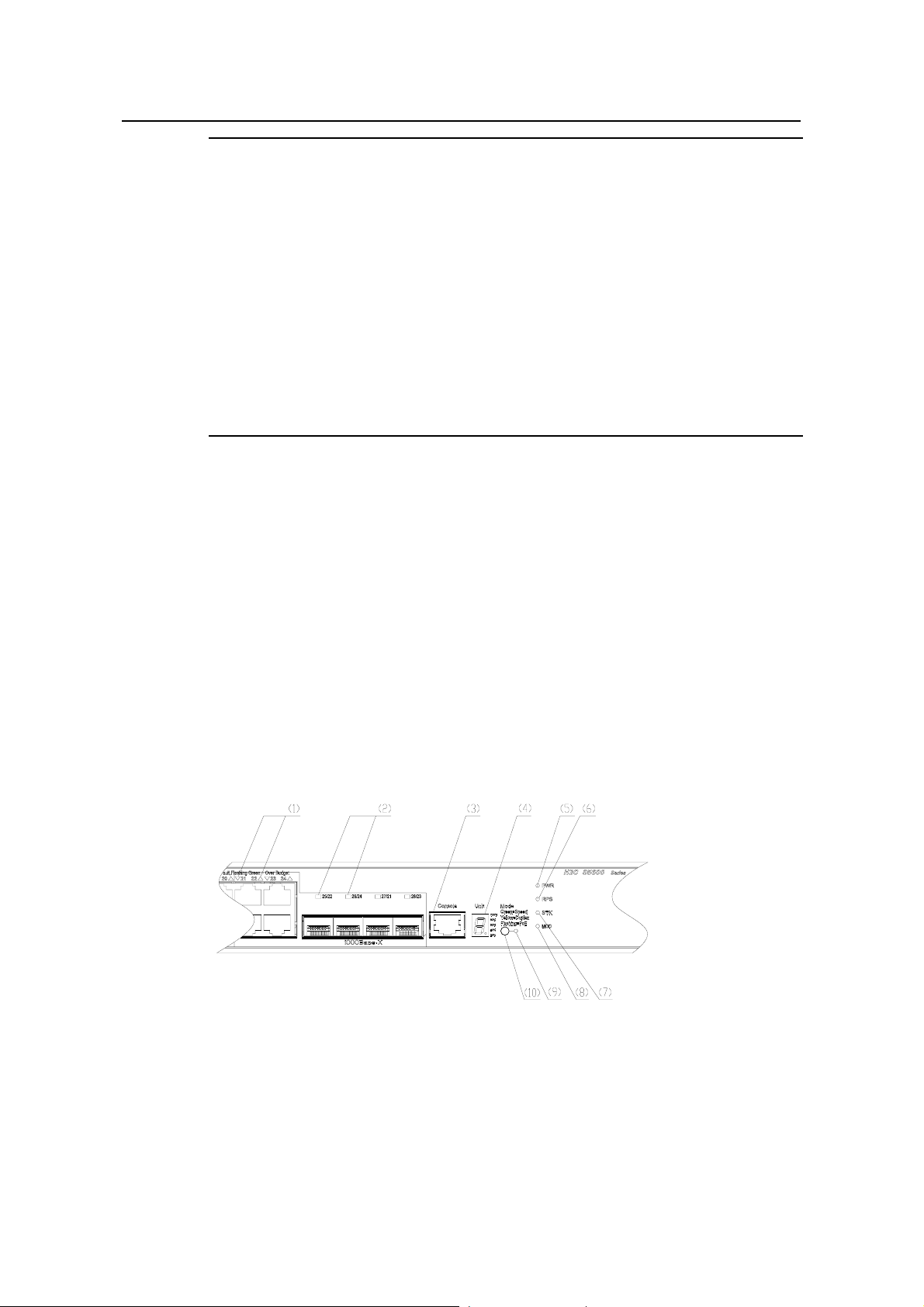
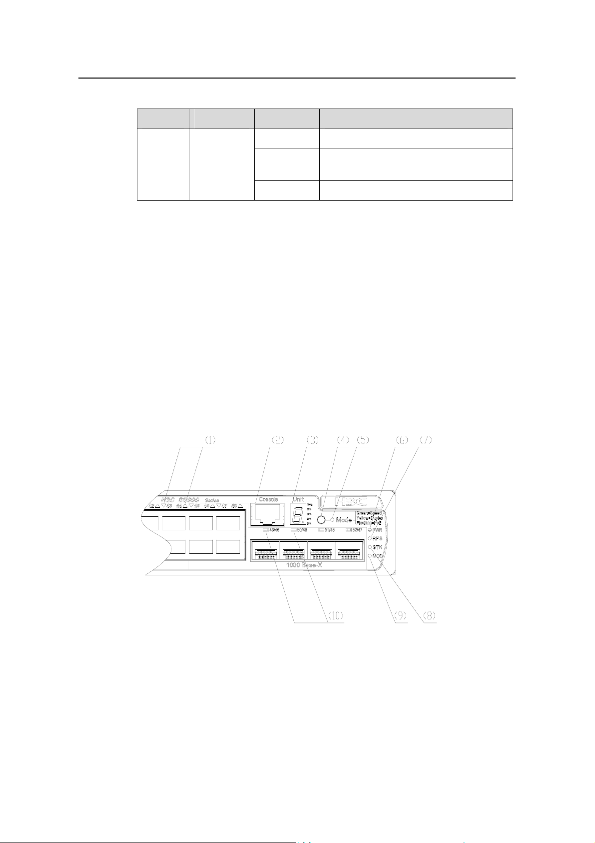
The S5600-26C/S5600-26C-PWR provides 24 x 10/100/1000Base-TX Ethernet ports,
one Console port, and four 1000 Mbps SFP Combo ports on its front panel. Each SFP
port and the corresponding 10/100/1000M Ethernet port form a Combo port. For each
Combo port, the SFP port and the 10/100/1000M Ethernet port cannot be used at the
same time. For the relationship between the Combo ports and the Ethernet po rt s, refer
Table 1-2.
to
Figure 1-1 shows the front panel of an S5600-26C Ethernet swit ch.:
(1) 10/100/1000M auto-negotiation Ethernet port status LEDs
(2) 1000 Mbps SFP Combo port LED (3) Console port
(4) 7-segment digitron display (5) Power LED
(6) DC LED (7) Fabric LED
(8) Module LED (9) Port mode LED
(10) Mode button
Figure 1-1 Front panel of the S5600-26C/S5600-26C-PWR
1-2
Page 9
Installation Manual
H3C S5600 Series Ethernet Switches Chapter 1 Product Overview
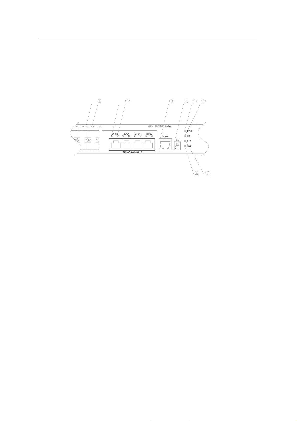
The S5600-26F provides 24 x 1000 Mbps SFP optical port s, one Console port, and four
1000 Mbps RJ-45 Combo ports on it s front panel. Each SFP port a nd the corresponding
10/100/1000M Ethernet port form a Combo port. For each Combo port, the SFP port
and the 10/100/1000M Ethernet port cannot be used at the same time. For the
relationship between the Combo ports and the Ethernet ports, refer to
Table 1-2.
Figure 1-2. shows the front panel of an S5600-26F Ethernet switch.:
(1) SFP optical port status LED
(2) 10/100/1000M auto-negotiation Ethernet port status LEDs: left one for speed, right one for
duplex mode
(3) Console port (4) 7-segment digitron display
(5) Power LED (6) RPS LED
(7) Fabric LED (8) Modul e LED
Figure 1-2 Front panel of the S5600-26F
II. LEDs
The S5600-26C/S5600-26C-PWR provides one power LED, one RPS LED, one fabric
LED, one module LED, one mode LED, one 7-segment digitron display, four pairs of
1000 Mbps SFP port status LEDs, and 24 pairs of 10/100/1000M port status LEDs on
its front panel.
The S5600-26F provides one power LED, one RPS LED, one fabric LED, one module
LED, one 7-segment digitron display , 24 pairs of 1000 Mbp s SFP port status LEDs, and
four pairs of 10/100/1000M auto-negotiation Ethernet port status LEDs on its front
panel.
Table 1-3 and Table 1-4 describe respectively the LEDs on the
S5600-26C/S5600-26C-PWR and S5600-26F.
1-3
Page 10

Installation Manual
H3C S5600 Series Ethernet Switches Chapter 1 Product Overview
Table 1-3 LEDs on the S5600-26C/S5600-26C-PWR
LED Mark Status Description
Mode LED Mode
Power
LED
PWR
DC LED RPS
Speed Solid green
Duplex Solid yellow
PoE
Blinking green
(at 1 Hz)
The port status LEDs are
showing the speed of each port.
The port LEDs are showing the
duplex mode of each port.
The port LEDs are showing the
PoE status of each port.
Solid green The switch is started normally.
Blinking green (at 1 Hz)
Solid red
Blinking yellow (at 1 Hz)
The system is running power-on
self-test (POST).
The system fails the POST, or
there is another fault.
Some ports fail the POST and
do not function.
OFF The switch is power-off.
Solid green
Both the AC power supply and
the DC input operate normally.
The AC power supply fails or the
Solid yellow
AC input is disconnected, while
the DC input operates normally.
Fabric
LED
STK
OFF DC input is disconnected.
The device is in the ring fabric
Green
status; the LED blinks quickly
when the fabric port is receiving
or sending data.
The device is in the daisy chain
Yellow
fabric status; the LED blinks
quickly when the fabric port is
receiving or sending data.
This device is isolated from the
Blinking green (at 3 Hz)
whole set of fabric devices
(effective when this device is in
the fabric status).
OFF
Neither of the two fabric ports is
connected.
1-4
Page 11
Installation Manual
H3C S5600 Series Ethernet Switches Chapter 1 Product Overview
LED Mark Status Description
Module
LED
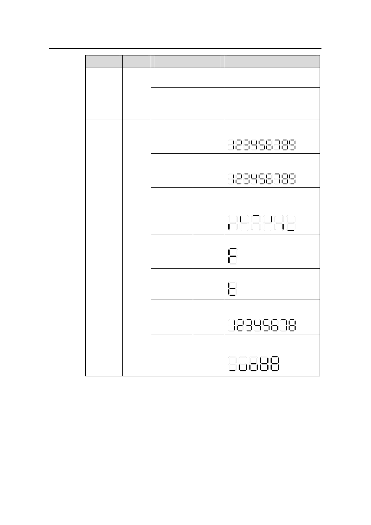
7-segment
digitron
display
Module
(MOD)
Unit
Solid green
Blinking yellow
The module is seated and
operates normally.
The module fails or is not
supported.
OFF No module is installed.
The POST ID of the in-process
POST
running
Blinking
green
test is displayed:
The POST ID of the failed test
POST failed
Blinking
red
blinks.
A light bar rotates clockwise
around the display during the
Software
downloading
Blinking
green
downloading procedure.
An “F” is displayed.
Fan failed Solid red
Over
temperature
alarm
Speed and
duplex
mode
PoE mode
Solid red
Solid
green
Solid
green
A “t” is displayed.
UNIT ID in the fabric; or “1” for a
standalone unit is displayed.
The utilization of the power
supply is displayed.
81 - 100%
61 - 80%
41 - 60%
21 - 40%
0 - 20%
1-5
Page 12

Installation Manual
H3C S5600 Series Ethernet Switches Chapter 1 Product Overview
LED Mark Status Description
The port is operating at 1000
Green
Mbps. The LED blinks quickly
when the port is receiving or
sending data.
The port is operating at 10/100
Speed mode
Yellow
Mbps. The LED blinks quickly
when the port is receiving or
sending data.
Blinking
yellow
The port fails the POST.
(at 3 Hz)
OFF The port is not connected.
The port is operating in full
Green
duplex mode. The LED blinks
quickly when the port is
receiving or sending data.
The port is operating in half
duplex mode. The LED blinks
quickly when the port is
receiving or sending data.
The port fails the POST.
10/100/
1000M
autonegotiation
Ethernet
—
Duplex
mode
Yellow
Blinking
Yellow
(3 Hz)
port status
LED
OFF The port is not connected.
PoE mode
Solid
green
The port supplies power
normally.
The connected device requires
Blinking
green
(at 1 Hz)
more power than the maximum
power a port can supply.
The port cannot supply power
because the switch has reached
its maximum power supplied.
The port cannot supply power
because the connected device is
Solid
yellow
not a PD.
The port cannot supply power
due to the power source failure
of PoE.
Blinking
yellow (3
The port fails the POST.
Hz)
OFF The port does not supply power.
1-6
Page 13
Installation Manual
H3C S5600 Series Ethernet Switches Chapter 1 Product Overview
LED Mark Status Description
The port is operating at 1000
Green
Mbps. The LED blinks quickly
when the port is receiving or
sending data.
Speed mode
Blinking
yellow (3
The port fails the POST.
Hz)
1000M
Base SFP
port mode
LED
—
OFF The port is not connected.
The port is operating in 1000
Green
Mbps full duplex mode. The LED
blinks quickly when the port is
receiving or sending data.
Duplex
mode
Blinking
yellow (3
The port fails the POST.
Hz)
OFF The port is not connected.
PoE mode OFF
–
Table 1-4 LEDs on the S5600-26F
LED Mark Status Description
Solid green The switch is started normally .
The system is running power-on
self-test (POST).
The system fails the POST, or
there is another fault.
Power
LED
PWR
Blinking green (at 1 Hz)
Solid red
DC LED RPS
Blinking yellow (at 1 Hz)
Some ports fail the POST and
do not function.
OFF The switch is power-off.
Solid green
Both the AC power supply and
the DC input operate normally.
The AC power supply fails or the
Solid yellow
AC input is disconnected, while
the DC input operates normally.
OFF DC input is disconnected.
1-7
Page 14
Installation Manual
H3C S5600 Series Ethernet Switches Chapter 1 Product Overview
LED Mark Status Description
The device is in the ring fabric
Green
status; the LED blinks quickly
when the fabric port is receiving
or sending data.
The device is in the daisy chain
fabric status; the LED blinks
quickly when the fabric port is
receiving or sending data.
Fabric
LED
Yellow
STK
This device is isolated from the
Blinking green (at 3 Hz)
whole set of fabric devices
(effective when this device is in
the fabric status).
Module
LED
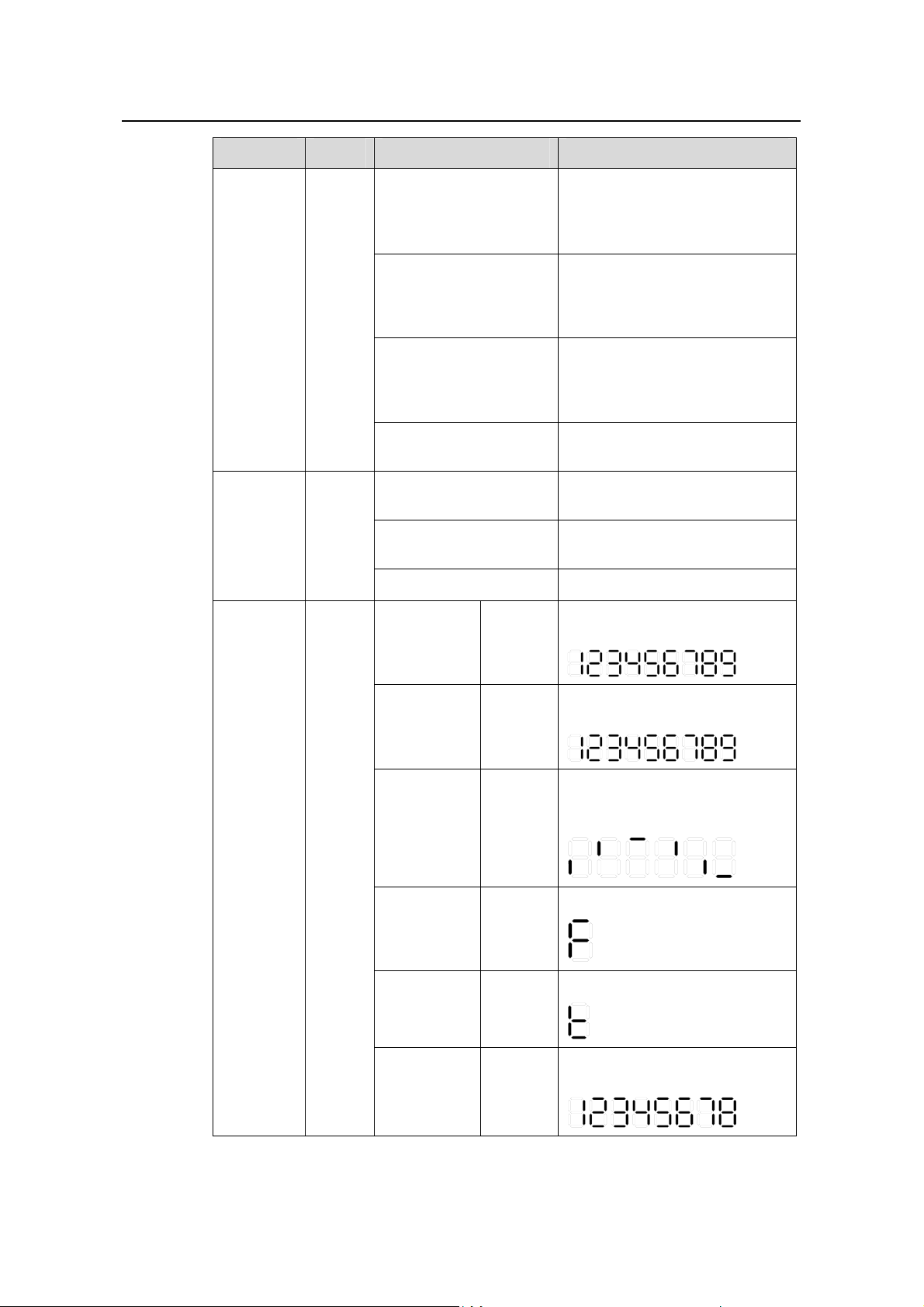
7-segment
digitron
display
Module
(MOD)
Unit
OFF
Solid green
Blinking yellow
Neither of the two fabric ports is
connected.
The module is seated and
operates normally.
The module fails or is not
supported.
OFF No module is installed.
The POST ID of the in-process
POST
running
Blinking
green
test is displayed:
The POST ID of the failed test
POST failed
Blinking
red
blinks.
A light bar rotates clockwise
around the display during the
Software
downloading
Blinking
green
downloading procedure.
An “F” is displayed.
Fan failed Solid red
Over
temperature
alarm
Speed and
duplex mode
1-8
Solid red
Solid
green
A “t” is displayed.
UNIT ID in the fabric; or “1” for a
standalone unit is displayed.
Page 15

Installation Manual
H3C S5600 Series Ethernet Switches Chapter 1 Product Overview
LED Mark Status Description
The port is operating at 1000
Green
Mbps. The LED blinks quickly
when the port is receiving or
sending data.
The port is operating at 10/100
Speed mode
Yellow
Mbps. The LED blinks quickly
when the port is receiving or
sending data.
Blinking
10/100/
1000M
autonegotiation
Ethernet
port status
LED
—
yellow
(at 3 Hz)
OFF The port is not connected.
Green
The port fails the POST.
The port is operating in full
duplex mode. The LED blinks
quickly when the port is
receiving or sending data.
The port is operating in half
Duplex
mode
Yellow
duplex mode. The LED blinks
quickly when the port is
receiving or sending data.
Blinking
Yellow
The port fails the POST.
(3 Hz)
OFF The port is not connected.
The port is operating at 1000
Mbps. The LED blinks quickly
when the port is receiving or
sending data.
The port fails the POST.
1000Base
SFP
optical port
status LED
—
Green
port status
LED
Blinking
yellow (3
Hz)
OFF The port is not connected.
III. Console port
The S5600-26C/S5600-26C-PWR/S5600-26F provides an EIA/TIA-232-compliant
Console port, which enables you to configure the switch from the local or remote site.
Table 1-5 Attributes of the Console port
Item Description
Connector RJ-45
Standard EIA/TIA-232
1-9
Page 16
Installation Manual
H3C S5600 Series Ethernet Switches Chapter 1 Product Overview
Item Description
Baud rate 9600 bps (default), auto-negotiation is supported
Connection to an ASCII terminal
Services
Connection to the serial port of a local terminal (a PC for
example) or a remote terminal (through a pair of modems)
running terminal emulation software
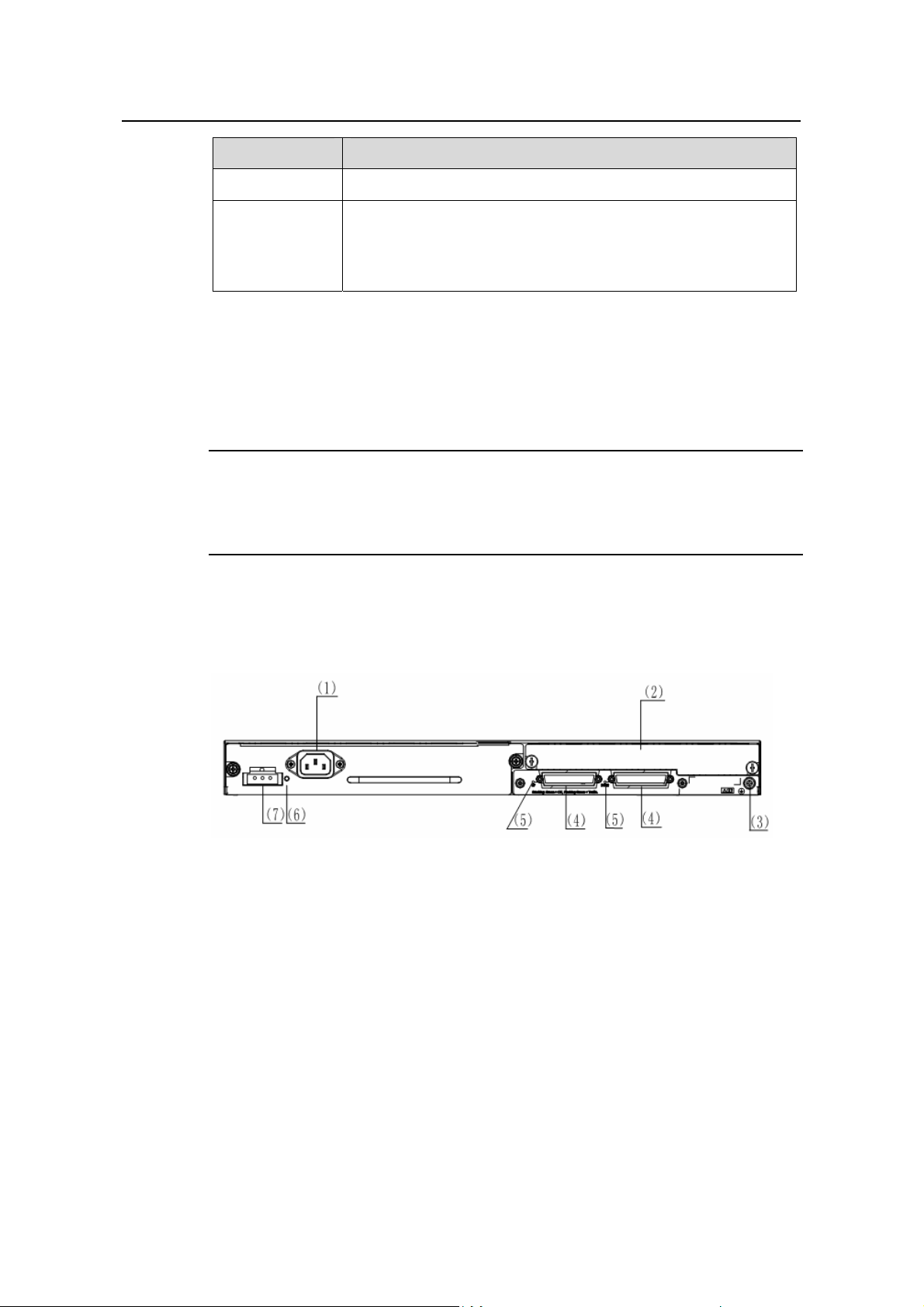
1.2.2 Rear Panel
I. Rear panel
Note:
The ports of the AC/DC dual input power module and the PoE power module are
exactly the same, so only one rear panel illustration is shown below.
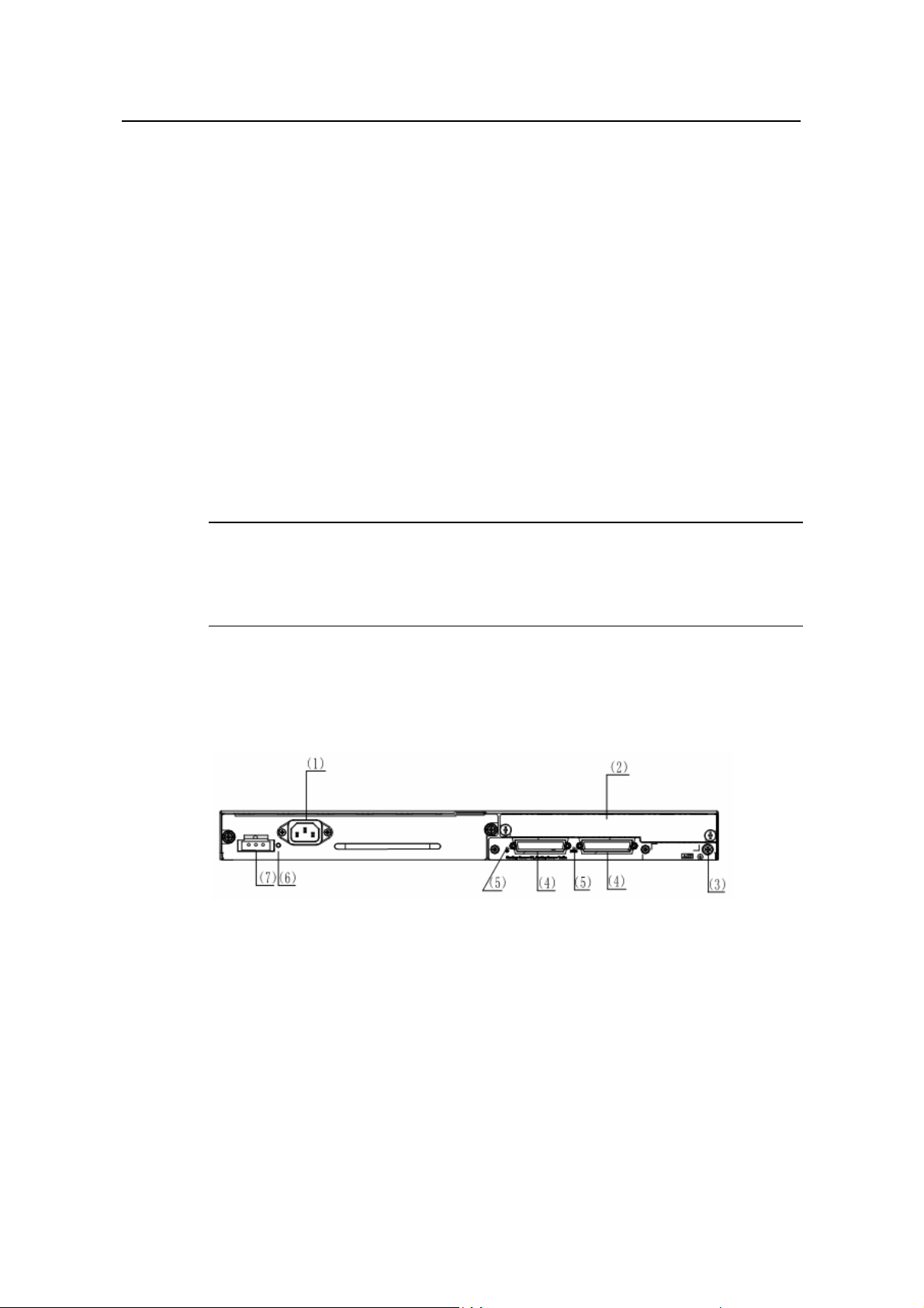
The S5600-26C/S5600-26C-PWR/S5600-26F provides two sockets for pluggable
power module, two fabric ports, one expansion slot, and one grounding screw on its
rear panel, as shown in the following figure.
(1) AC-input power socket for the power module (2) Expansion module
(3) Grounding screw (4) Fabric ports
(5) Fabric port LEDs (6) RPS LED
(7) DC-input power socket for the power module
Figure 1-3 Rear panel of the S5600-26C/S5600-26C-PWR/S5600-26F
II. Fabric port
The fabric port marked with “UP” connects to a port of the same type on an upstream
device; the fabric port marked with “DOWN” connects to a port of the same type on a
downstream device.
1-10
Page 17
Installation Manual
H3C S5600 Series Ethernet Switches Chapter 1 Product Overview
Table 1-6 Fabric port LEDs
LED Mark Status Indicate
Solid green The fabric port is properly connected.
Fabric
port LED
UP(DOWN)
Blinking
green
The fabric port is properly connected and
the port is receiving or sending data.
OFF The fabric port is disconnected.
1.3 S5600-50C/S5600-50C-PWR Ethernet Switch
1.3.1 Front Panel
I. Front panel
The S5600-50C/S5600-50C-PWR provides 48 x 10/100/1000Base-TX Ethernet ports,
one Console port, and four 1000 Mbps SFP Combo ports on its front panel. Each SFP
port and the corresponding 10/100/1000M Ethernet port form a Combo port. For each
Combo port, the SFP port and the 10/100/1000M Ethernet port cannot be used at the
same time. For the relationship between the Combo ports and the Ethernet po rt s, refer
Table 1-2.
to
Figure 1-4 shows the front panel of an S5600-50C/S5600-50C-PWR Ethern et switch:
(1) 10/100/1000M auto-negotiation Ethernet port status LEDs
(2) Console Port
(3) 7-segment digitron display (4) Mode button
(5) Mode LED (6) Power LED
(7) RPS LED (8) Fabric LED
(9) Module LED (10) 1000 Mbps SFP combo port LED
Figure 1-4 Front panel of the S5600-50C/S5600-50C-PWR
1-11
Page 18
Installation Manual
H3C S5600 Series Ethernet Switches Chapter 1 Product Overview
II. LEDs
The S5600-50C/S5600-50C-PWR provides one power LED, RPS LED, fabric LED,
module LED, mode LED, 7-segment digitron display, 1000 Mbps SFP port status LED,
and auto-negotiation Ethernet port status LED on its front panel. The meaning of each
LED is shown in
Table 1-3
III. Console port
The S5600-50C/S5600-50C-PWR provides an EIA/TIA-232-compliant console port,
which enables you to configure the switch from the local or remote site. For the
attributes of the port, refer to
Table 1-5.
1.3.2 Rear panel
I. Rear panel
Note:
The ports of the AC/DC dual input power module and the PoE power module are
exactly the same, so only one rear panel illustration is shown below.
The S5600-50C/S5600-50C-PWR provides two sockets for pluggable power module,
two fabric ports, one expansion slot, and one grounding screw on its rear panel, as
shown in the following figure.
(1) AC-input power socket for the power module (2) Expansion module
(3) Grounding screw (4) Fabric ports
(5) Fabric port LEDs (6) RPS LED
(7) DC-input power socket for the power module
Figure 1-5 Rear panel of the S5600-50C/S5600-50C-PWR
II. Fabric ports
For fabric ports and the meanings of their LEDs, refer to Table 1-6.
1-12
Page 19

Installation Manual
H3C S5600 Series Ethernet Switches Chapter 1 Product Overview
1.4 Power system
z AC power input range
Rated voltage: 100 to 240 VAC; 50/60 Hz
Max. voltage range: 90 to 264 VAC; 50/60 Hz
z DC power input range
Rated voltage: –48 to–60 V
Max. voltage range: –36 to–72 V
z AC input of the PoE power module
Rated voltage: 100 to 240 VAC; 50/60 Hz
Max. voltage range: 90 to 264 VAC; 50/60 Hz
z DC input of the PoE power module
Rated voltage: –53.5 V
Max. voltage range: –52 to –55 V
Note:
The S5600-26C-PWR/S5600-50C-PWR must use the external PoE PSU
recommended by H3C as its DC input, but not the -48VDC power supply generally
available in the equipment room. Otherwise, the device may be damaged.
1.5 Cooling system
S3100-8TP-PWR-EI Ethernet switches each run two fans for heat dissipation.
Table 1-7 S5600 Ethernet switches cooling system
Model S5600-26C S5600-26C-PWR S5600-26F
Cooling system
Two fans are for the
device and two are
for the power supply
module.
(1)
Two fans are for
the device and four
are for the power
supply module.
Four fans are for
the device and two
are for the power
supply module.
1-13
Page 20
Installation Manual
H3C S5600 Series Ethernet Switches Chapter 1 Product Overview
Table 1-8 S5600 Ethernet switches cooling system (2)
Model S5600-50C S5600-26C-PWR
Two fans are for the device
Cooling system
and two are for the power
supply module.
1.6 Attributes of 1000 Mbps SFP port
The S5600-26C/S5600-26C-PWR/S5600-50C/S5600-50C-PWR provides 4 × 1000
Mbps SFP ports on it s front panel. Th e S5600-26F provides 24 × 1000 Mb ps SFP ports
on its front panel.
SFP modules allow for great flexibility in networking because they are hot swappable
and user configurable.
Table 1-9 lists the available SFP modules that you can select as required:
Table 1-9 Optical port module
Type Model
Two fans are for the device and
four are for the power supply
module.
SFP-GE-SX-MM850-A
SFP-GE-LX-SM1310-A
SFP
module
1000M SFP module
SFP-GE-LH40-SM1310
SFP-GE-LH40-SM1550
SFP-GE-LH70-SM1550
SFP electrical interface module SFP-GE-T
Note:
z Only the optical module that H3C Technology provides or recommends can be
used.
z The types of SFP modules may vary with time. Consult H3C marketing personnel or
technical support personnel to obtain the latest information about SFP modules.
z For specifications of SFP modules, refer to H3C Low End Series Ethernet Switches
Pluggable Module Manual.
1-14
Page 21
Installation Manual
H3C S5600 Series Ethernet Switches Chapter 1 Product Overview
1.7 Expansion Module
The S5600 Series Ethernet switches provide one expansion module slot on the rear
panel. The expansion mode that can be used in this slot includes 8-port 1000 Mbps
SFP module, 1-port 10 Gbps XENPAK module, and 2-port 10 Gbps XFP module.
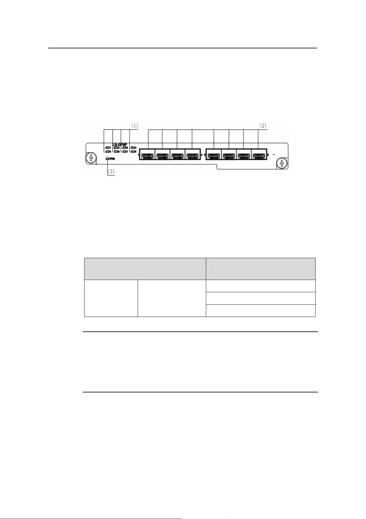
I. 8-port 1000 Mbps SFP module
(1) Port status LEDs (2) SFP ports (3) Module power LED
Figure 1-6 8-port 1000 Mbps SFP module
This module provides eight 1000 Mbps SFP external optical/electrical ports.
z For an optical port, you can choose one of the following SFP modules according to
your needs.
Table 1-10 Optical port module supported by 8-port 1000 Mbps SFP module
SFP module
Central wavelength
Maximum transmission distance
Fiber specifications
SFP-GE-SX-MM850-A
SFP module 1000M SFP module
SFP-GE-LX-SM1310-A
SFP-GE-LH40-SM1310
Note:
z The types of SFP modules may vary with time. Consult H3C marketing personnel or
technical support personnel to obtain the latest information about SFP modules.
z For specifications of SFP modules, refer to H3C Low End Series Ethernet Switches
Pluggable Module Manual.
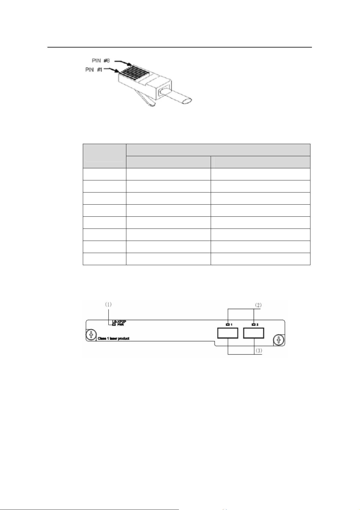
z For an RJ-45 electrical port with the transmission distance is 100 m (328 ft), you
can select the RJ-45 connector as shown in the following figure, and the
category-5 twisted pair as the data transmission medium.
1-15
Page 22
Installation Manual
H3C S5600 Series Ethernet Switches Chapter 1 Product Overview
Figure 1-7 RJ-45 connector
Table 1-11 Pinouts of the RJ-45 GE port
Pin
1000Base-TX
Signal Function
1 MX_0+ Data transmit/receive
2 MX_0- Data transmit/receive
3 MX_1+ Data transmit/receive
4 MX_2+ Data transmit/receive
5 MX_2- Data transmit/receive
6 MX_1- Data transmit/receive
7 MX_3+ Data transmit/receive
8 MX_3- Data transmit/receive
II. 2-port 10 Gbps XFP module
(1) Module power LED (2) Port status LEDs (3) 10 Gbps XFP optical ports
Figure 1-8 2-port 10 Gbps XFP module
This module provide two 10 Gbps XFP optical port. The following table lists the
available XFP optical modules that you can select according to your need s:
1-16
Page 23

Installation Manual
H3C S5600 Series Ethernet Switches Chapter 1 Product Overview
Table 1-12 XFP optical port module supported by 2-port 10 Gbps XFP module
Type Model
XFP-SX-MM850
XFP optical module
XFP-LX-SM1310
XFP-LH40-SM1550-F1
Note:
z The switch does not support the 10GBase-ER-XFP module with -5.2 V power
supply.
z The type of 10 Gbps XFP module may be different from those listed above. For the
accurate information about the module type, please consult market personnel or
technical support personnel of H3C.
z For specifications of SFP modules, refer to H3C Low End Series Ethernet Switches
Pluggable Module Manual.
III. 1-port 10 Gbps XENPAK module
(1) Module power LED (2) Port status LED
(3) 10 Gbps XENPAK optical/electrical port
Figure 1-9 1-port 10 Gbps XENPAK module
z This module can provide one 10 Gbps XENPAK optical port. The following table
lists the available XENPAK optical modules:
Table 1-13 XENPAK optical port module supported by 1-port 10 Gbps XENPAK
module
Type Model
XENPAK-LX-SM1310
XENPAK optical module
XENPAK-LH40-SM1550
1-17
Page 24

Installation Manual
H3C S5600 Series Ethernet Switches Chapter 1 Product Overview
z This module can also provide a 10 Gbps electrical port. When using this port, you
must select the CX4 connector, and the InfiniBand cable with the transmission
distance of 15 m (49.2 ft).
Note:
z For specifications of SFP modules, refer to H3C Low End Series Ethernet Switches
Pluggable Module Manual.
z Use the CX4 modules or the XENPAK optic port modules that H3C Technology
provides or recommends.
1.8 S5600 Series Technical Specifications
Table 1-14 System specifications of the S5600 series
Item
S5600-
26C
S5600-26C
-PWR
S5600-26F
S5600-
50C
50C-PWR
Physical
dimensions (H x
43.6 x 440 x 420 mm (1.7 x 17.3 x 16.5 in)
W x D)
Weight <7.5kg (16.5 lb) <8kg (17.6 lb)
Port switching
capacity
88Gbit/s 136Gbit/s
24 x 1000
Fixed port
24 x 10/100/1000
Mbps electrical ports
and four SFP combo
ports
Mbps SFP
ports and
four
electrical
48 x 10/100/1000
Mbps electrical ports
and four SFP combo
ports
combo ports
Management
port
Number of
expansion slot
One console port
1
S5600-
1-18
Page 25

Installation Manual
H3C S5600 Series Ethernet Switches Chapter 1 Product Overview
Item
S5600-
26C
S5600-26C
-PWR
S5600-26F
S5600-
50C
S5600-
50C-PWR
PSL130-AD: 130 W system output, AC/DC input
PSL480-AD24P: 24-port PoE power module, 180 W system
output + 300 W PoE output (AC input); 180 W system output +
Power
module
370 W PoE output (DC input)
PSL180-AD: 180 W system output, AC/DC input
PSL480-AD48P: 48-port PoE power module, 180 W system
output + 300 W PoE output (AC input); 180 W system output +
740 W PoE output (DC input)
The input voltage of the AC/DC dual input power module:
AC input:
Rated voltage: 100 VAC to 240 VAC, 50 Hz or 60Hz
Maximum tolerance:90 VAC to 264 VAC, 50 Hz or 60Hz
DC input:
Power
supply
Rated voltage: –48 VDC to –60 VDC
Maximum tolerance: –36 VDC to –72 VDC
Input
voltage
RPS
power
Power
consumption (full
load)
The AC input of the PoE power module:
Rated voltage: 100 VAC to 240 VAC, 50 Hz or 60 Hz
Max voltage range: 90 VAC to 264 VAC, 50 Hz or 60 Hz
The DC input of the PoE power module:
Rated voltage: –53.5 VDC
Max voltage range: –52 VDC to–55 VDC
For S5600-26C-PWR/S5600-50C-PWR, use the external RPS
recommended by H3C as the DC power input instead of the
–
48 VDC power supply generally available in the equipment
room. Any violation may damage the device due to overvoltage.
Supported
600W
When with
PoE
power
supply:
970 W
(DC input),
640 W (AC
input)
170W
540W
When with
PoE power
supply:
540 W (DC
input),
560 W (AC
input)
170W 230W
1-19
Page 26

Installation Manual
H3C S5600 Series Ethernet Switches Chapter 1 Product Overview
Item
S5600-
26C
S5600-26C
-PWR
S5600-26F
S5600-
50C
S5600-
50C-PWR
Fans (for heat
dissipation)
Operating
temperature
Operating
humidity
(non-condensing
)
Two
fans are
for the
device
and two
are for
the
power
supply
Two fans
are for the
device and
four are for
the power
supply
module.
module.
o
0 to 45
C
10% to 90%
Four fans
are for the
device and
two are for
the power
supply
module.
Two fans
are for
the
device
and two
are for
the
power
supply
module.
Two fans
are for the
device and
four are for
the power
supply
module.
1-20
Page 27

Installation Manual
H3C S5600 Series Ethernet Switches Chapter 2 Preparing for Installation
Chapter 2 Preparing for Installation
2.1 Safety Precautions
To avoid any device impairment and bodily injury caused by improper use, observe
these rules:
z Before cleaning the switch, unplug the power plug of the switch first. Do not clean
the switch with wet cloth or liquid.
z Do not place the switch near water or any damp area. Prevent water or moisture
from entering the switch chassis.
z Do not place the switch on an unstable case or desk. The switch might be
damaged severely in case of a fall.
z Ensure proper ventilation of the equipment room and keep the ventilation vents of
the switch free of obstruction.
z Make sure that the operating voltage is the same one labeled on the switch.
z Do not open the chassis while the switch is operating or when electrical hazards
are present to avoid electrical shocks.
z When replacing interface cards, wear ESD-protective gloves to avoid damaging
the cards.
2.2 Installation Site
The S5600 series must be used indoors. You can mount your switch in a rack or on a
tabletop/workbench, but make sure:
z Adequate clearance is reserved at the air inlet/exhaust vents for ventilation.
z The rack or table/workbench has a good ventilation system.
z The rack is sturdy enough to support the device and its accessories.
z The rack or table/workbench is well earthed.
To ensure normal operation and long service life of your VG, inst all it in an environment
that meets the requirements described in the following subsections.
2.2.1 Temperature/Humidity
You must maintain a proper temperature and humidity in the equipment room.
Long-term high humidity may lead to bad insulation, electricity leakage, mechanical
property changes, and corrosion. However, if the relative humidity is two low, captive
screws may become loose as the result of contraction of insulation washers and static
electricity may be produced in a dry environment to jeopardize the CMOS circuits on
the device. High temperature is the most undesirable condition, because it accel erates
2-1
Page 28

Installation Manual
H3C S5600 Series Ethernet Switches Chapter 2 Preparing for Installation
aging of insulation materials and can thus significantly lower reliability and service life of
your switch.
For the temperature and humidity requirements of dif ferent models, refer to se ction
S5600 Series Technical Specifications.
2.2.2 Cleanness
Dust is a hazard to the operating safety of your device. The dust accumulated on the
chassis can be adsorbed by static electricity and result in poor contact of metal
connectors or metal contact points. This cannot only shorten the service life of your
device but also cause communications failures. When the relative indoor humidity is
low, electrostatic adsorption is more likely to happen. The contents of the dust must be
limited as shown in the
Table 2-1 Dust content limits in an equipment room
Substance Unit Content
Dust Particles/m³
Remark: the diameter of a dust particle ≥ 5 μm
Table 2-1:
≤ 3 X 10
4
(No visible dust on the tabletop for three days)
1.8
Besides dust, there are rigorous limits on the harmful gases that can accelerate the
erosion and aging of metals, such as salts, acids, and sulfides, as shown in the
2-2.
Table 2-2 Harmful gas limits in the equipment room
Gas Maximum (mg/m3)
SO2 0.2
H2S 0.006
NH3 0.05
Cl2 0.01
2.2.3 Electromagnetic Susceptibility
The operation of your switch can be affected by external interferences, such as
conducted emission by capacitance coupling, inductance coupling, electromagnetic
wave radiation, and common impedance (including the grounding system) coupling,
and leads (power cords, signaling cables and output wires. To eliminate the
interferences, make sure to:
Table
2-2
Page 29

Installation Manual
H3C S5600 Series Ethernet Switches Chapter 2 Preparing for Installation
z For the AC power supply that adopts TN system, use a monophase three-line
power socket with Protection Earth (PE) to effectively filter interference from the
power grid.
z Keep the device far from radio transmitting stations, radar stations, and
high-frequency devices.
z Use electromagnetic shielding when necessary, for example, use shielded
interface cables.
z Route interface cables only indoors to prevent signal ports from getting damaged
by overvoltage or overcurrent caused by lightning strikes.
2.2.4 Laser Safety
The S5600 Series Ethernet Switches are class-1 laser devices.
If the optical boards on your switch are operating, do not stare into the optical ports
because the laser light emitted by the optical fiber can hurt your retina.
Caution:
Staring into the laser beam produced by the fiber can hurt your eyes.
2.3 Installation Tools
z Flat-blade screwdriver
z Phillips screwdriver
z ESD-preventive wrist strap
Caution:
The installation tools are not provided with the S5600 series.
2-3
Page 30

Installation Manual
H3C S5600 Series Ethernet Switches Chapter 3 Installing the Switch
Chapter 3 Installing the Switch
Caution:
When you ask your sales agent to maintain the switch, you must ensure that the
dismantlement-preventive seal on a mounting screw of the switch chassis is intact. If
you want to open the chassis, you should contact the agent for permission. Otherwise,
you will bear any consequence resulted from your actions without permission.
3.1 Rack-Mounting the Switch
You can install a switch into a 19-inch standard cabinet in one of the following three
ways:
z Use front mounting ears and a tray
z Use front mounting ears and rear mounting ears
z Use front mounting ears and guide rails
Note:
z The front mounting ears and rear mounting ears are delivered with the device, no
guide rails are delivered with the device.
z The front mounting ears only secure the switch rather than bear its weight.
z Guide rails purchased from H3C apply only to standard cabinets 1,000 mm (39.4 in)
deep. Use other supports to substitute for guide rails in the case of other cabinet
depths.
3.1.1 Introduction to mounting ear
Figure 3-1 shows the appearance of a front mounting ear.
3-1
Page 31

Installation Manual
H3C S5600 Series Ethernet Switches Chapter 3 Installing the Switch
(1) (2)
L1
L2
(1): Screw hole used to fix the mounting ear to the cabinet (Use one M6 screw)
(2): Screw hole used to fix the switch to the mounting ear
Figure 3-1 Appearance of a front mounting ear
Figure 3-2 shows the appearance of a rear mounting ear.
(1): Screw hole used to fix the mounting ear to the cabinet (Use one M6 screw)
Figure 3-2 Appearance of a rear mounting ear
3.1.2 Introduction to guide rail
Figure 3-3 shows the appearance of a guide rail.
3-2
Page 32

Installation Manual
2
H3C S5600 Series Ethernet Switches Chapter 3 Installing the Switch
Slotted hole 1 Cooling hole Slotted hole
Slotted hole 1: Used to fix the guide rail to the rear bracket. You can adjust the screw hole
position according to the position of the switch.
Cooling hole: Used for heat dissipation between switch and cabinet
Slotted hole 2: Used to fix the guide rail to the front bracket
Figure 3-3 Appearance of a guide rail
3.1.3 Use front mounting ears and a tray
Follow these steps to install a switch into a 19-inch standard cabinet:
1) Wear an ESD-preventive wrist strap to check the grounding and stability of the
cabinet.
2) Fix the delivered tray horizontally in a proper position.
3) Take out the screws which are packed together with the front mounting ears, and
fix one end of mounting ears to the switch, as shown in
Figure 3-4.
Front panel
Figure 3-4 Fix front mounting ears
4) Place the switch on the tray horizontally, slide the tray into the cabinet, and fix the
other end of mounting ears to the front brackets with crews and captive nuts, as
shown in
Figure 3-5.
3-3
Page 33

Installation Manual
H3C S5600 Series Ethernet Switches Chapter 3 Installing the Switch
Fr ont squar e-holed brac k et
Fr ont squar e-holed brac k et
Front mounting ear
Front mounting ear
Fr ont panel
Fr ont panel
Front
Front
mounting ear
mounting ear
Figure 3-5 Fix front mounting ears and a tray
3.1.4 Use front and rear mounting ears
Follow these steps to install a switch into a 19-inch standard cabinet:
1) Wear an ESD-preventive wrist strap to check the grounding and stability of the
cabinet.
2) Take out the screws which are packed together with the front mounting ears, and
fix one end of mounting ears to the switch, as shown in
3) Take out the load-bearing screws (packed together with the rear mounting ears)
and place them in a proper position on the sides of the switch, as sh own in
3-6.
Three installation locations for screw 1 (select one accordi ng to the actual require m ent)
Three installation locations for screw 1 (select one accordi ng to the actual require m ent)
Screw 1
Screw 1
Screw 1
Screw 1
Fron t panel
Fron t panel
Figure 3-4.
mounting ear
mounting ear
Front
Front
Figure
Fron t mounti ng ear
Fron t mounti ng ear
Figure 3-6 Fix front mounting ears and load-bearing screws
3-4
Page 34

Installation Manual
k
H3C S5600 Series Ethernet Switches Chapter 3 Installing the Switch
Note:
There are three positions to mount a load-bearing screw on both sides of a switch. You
should select a proper position according to the actual requirements. The rear
mounting ears tightly contacted with the load-bearing screws can support the switch.
4) Select a position to install the switch and fix the rear mounting ears to the rear
brackets with screws and captive nuts, as shown in
Figure 3-7.
Rear square-holed rac
Figure 3-7 Fix rear mounting ears
5) Hold the bottom of the switch with one hand and the front part of the switch with
the other hand, and pull the switch into the cabinet gently, as shown in
Figure 3-8.
3-5
Page 35

Installation Manual
r
H3C S5600 Series Ethernet Switches Chapter 3 Installing the Switch
Rear mounting ear
Screw 2
Front square-holed bracket
Rear square-holed
bracket
Front mounting ear
Screw 1: Used to bear the weight
Screw 2: Used to fix rear mounting ears to rear brackets
Rear panel
Figure 3-8 Fix front and rear mounting ears
After the switch is pushed into the cabinet, ensure that the upper edge of rear mounting
ears is tightly contacted with the load-bearing screw, as shown in
Figure 3-9.
Rear panel
Screw 1: Load-bearing screw
Rear square-
holed bracket
Screw 1
Rear mounting ea
Figure 3-9 Effect diagram of front and rear mounting ear installation (1)
6) Fix the other end of the front mounting ears to the front brackets with screws and
captive nuts and ensure that front and rear mounting ears have fixed the switch i n
the cabinet securely, as shown in
Figure 3-10.
3-6
Page 36

Installation Manual
H3C S5600 Series Ethernet Switches Chapter 3 Installing the Switch
Screw 1
Rear
mounting ear
Front panel
Front mounting ear
Front square-holed bracket
Screw 1: Load-bearing screw
Figure 3-10 Effect diagram of front and rear mounting ear installation (2)
3.1.5 Use front mounting ears and guide rails
Follow these steps to install a switch into a 19-inch standard cabinet
1) Wear an ESD-preventive wrist strap to check the grounding and stability of the
cabinet.
2) Take out the screwed packed together with the front mounting ears and fix one
end of the front mounting ears to the switch, as shown in
Figure 3-11.
Front panel
Figure 3-11 Fix front mounting ears
3) Install guide rails on the brackets on both sides of the cabinet with M5 self-tapping
screws, as shown in
Figure 3-12.
3-7
Page 37

Installation Manual
l
H3C S5600 Series Ethernet Switches Chapter 3 Installing the Switch
Figure 3-12 Install guide rails
4) Hold the two sides of the switch and slide it gently along the guide rails into the
cabinet until it is located in a proper position, as shown in
Figure 3-13. Ensure that
the bottom side of the guide rails and the switch are in close contact.
Front pane
Figure 3-13 Install front mounting ears and guide rails
5) Fix the other end of front mounting ears to the front brackets of the cabinet with M6
screws and captive nuts and ensure that the front mounting ears and guide rails
have fixed the switch in the cabinet securely, as shown in
3-8
Figure 3-14.
Page 38

Installation Manual
H3C S5600 Series Ethernet Switches Chapter 3 Installing the Switch
Rear panel
Guide
Figure 3-14 Effect diagram of front mounting ear and guide rail installation
Note:
rail
Ensure a clearance of 1U (44.45 mm, namely, 1.75 inches) between devices for the
purpose of heat dissipation.
3.2 Mounting the Switch on a Tabletop/Workbench
When placing the switch on a tabletop or workbench, you simply need to:
z Make sure that the tabletop or workbench is clean, flat, and sturdy.
z Allow 10 cm (3.9 in.) of clearance around the sides of the chassis.
z Do not place heavy objects on the switch.
3-9
Page 39

Installation Manual
H3C S5600 Series Ethernet Switches Chapter 3 Installing the Switch
3.3 Installing/Removing the Power Module
Caution:
To avoid bodily injury, do not touch any bare conducting wire, screw, and the part which
is labeled danger voltage.
3.3.1 Installing the Power Module
The power module of the S5600 series is swappable. Follow those steps to install the
power module:
Step 1: W ear an ESD wrist strip, and make sure it is well grounded.
Step 2: V erify that the power mod ule is not installed upside-do wn (the module should be
installed according to the letters. If the module is installed upside down, it will fail to be
fully seated due to the specially designed inside structure of the chassis). Use one
hand to hold the handle on the front, and another to hold the bottom. Slide it gently
along the power slot. Push the module until it is fully seated.
Step 3: Use a Phillips screwdriver to fasten the captive screws at both sides of the
module.
3.3.2 Removing the Power Module
The power module of S5600 series Ethernet switch is swappa ble. Follow those steps to
remove the power module:
Step 1: W ear an ESD wrist strip, and make sure it is well grounded.
Step 2: Disconnect all power of the switch.
Step 3: Use a Phillips screwdriver to unscrew the captive screws at both sides of the
module
Step 4: Use one hand to hold the handle on the front, and another to hold the top. Pull
out the module stably towards you along the power slot until it is completely apa rt from
the chassis bottom.
3-10
Page 40

Installation Manual
H3C S5600 Series Ethernet Switches Chapter 3 Installing the Switch
Caution:
When you use the Phillips screwdriver or power screwdriver to fasten captive screws at
both sides of the module, make sure the captive force moment is not larger than 0.4
N•m.
3.4 Connecting the Power Cord and the Ground Wire
3.4.1 Connecting the AC-Input Power Cord
I. AC-input power socket (recommended)
You are recommended to use a monophase three-line power socket with a ground
contact or a general purpose PC power socket, making sure that the power point is well
connected to building ground. Normally, the ground point of the power source in a
building was buried in the ground during the construction and wiring. Still, you must
make sure of that.
Neutral point
Ground
Neutral point
Ground
Return Hot
Return Hot
Zero line
Zero line
Live line
Live line
Figure 3-15 Power socket (recommended)
II. Connecting the AC-input power cord
Step 1: Connect on e end of the ch assis ground wire to the grounding scre w on the rear
of the chassis and the other end to the ground as near as possible.
Step 2: Connect one end of the power cord to the power socket on the rear of the
chassis, and plug the other end to the AC power jack of the power source.
Step 3: Check that the PWR LED on the front panel of the switch is ON.
Caution:
Before powering on the switch, connect the ground wire.
3-11
Page 41

Installation Manual
H3C S5600 Series Ethernet Switches Chapter 3 Installing the Switch
3.4.2 Connecting the DC-Input Power Cord
RTN: -48V working ground -48_-60V: -48_-60V NULL: reserved
Figure 3-16 DC-input power connector (partial)
Step 1: Connect on e end of the ch assis ground wire to the grounding scre w on the rear
of the chassis and the other end to the ground as near as possible.
Step 2: Connect DC-input socket.
Screw 2
Screw 1
Screw 1
Screw 2
Screw 3
Screw 3
Cable 1
Cable 1
Dust-proof shield
Dust-proof shield
Cable tie
Cable tie
Screw 4
Connector
Connector
Screw 4
Cable 2
Cable 2
Figure 3-17 RPS DC-input connector
(1) As shown in
Figure 3-17, first insert two cables into the appropriate holes through
dust-proof shield, and then fix the cables separately by using screws 1 and 2. Make
sure that the positive and negative ends of the cable are inserted appropriately and
accord with silkscreen on the holes.
(2) Fix the dust-proof shield by screws 3 and 4 by using a small flathead screwdriver,
Figure 3-17.
see
(3) Enlace the two cables to the polarizing key at the back of the dust-proof shield using
the cable tie, see
Figure 3-17.
3-12
Page 42

Installation Manual
H3C S5600 Series Ethernet Switches Chapter 3 Installing the Switch
Connector
Connector
component
component
Screw 2
Screw 2
Screw 1
Screw 1
Cabinet
Cabinet
Figure 3-18 Fix RPS connector to the cabinet
Step 3: After installing connector component, directly insert the component into
DC-input socket on the cabinet, and then fix the screws 1 and 2 carried by the
connector itself to the appropriate holes on the cabinet socket using a small flathead
screwdriver, see
Figure 3-18.
Step 4: Check that the RPS LED on the front panel of the switch is ON.
Caution:
z Before powering on the switch, connect the ground wire.
z The DC power cable should be less than 3 meters long.
z The S5600-26C-PWR/S5600-50C-PWR must use the external PoE PSU
recommended by H3C as its DC input, but not the -48VDC power supply generally
available in the equipment room. Otherwise, the device may be damaged.
3.4.3 Connecting the Ground Wire
Caution:
Correctly connecting the switch ground wire is crucial to the lightning protection and
electromagnetic susceptibility (EMS) of a switch.
The power input end of the switch is connected with a noise filter , whose central gro und
is directly connected to the chassis, forming the chassis ground (commonly known as
3-13
Page 43

Installation Manual
H3C S5600 Series Ethernet Switches Chapter 3 Installing the Switch
PGND). This chassis ground must be securely connected to the earth ground so that
the faradism and leakage electricity can be safely released to the ground, enhancing
the EMS capability of the switch.
Ground your switch as follows:
z When a grounding strip is available at the installation site, attach one end of the
yellow/green ground wire of the switch to the grounding screw on the grounding
strip and fasten the captive nut. (Note that the fire main and lightning rod of a
building are not suitable for grounding the switch. The ground wire of the switch
should be connected to the grounding device for the equipment room).
(2)
(1)
(1)
(2)
(3)
(3)
(4)
(4)
(1) Power input on the switch (2) Grounding screw on the switch
(3) Ground wire (4) Grounding strip
Figure 3-19 Grounding the switch through a grounding strip
z When there is no grounding strip but earth near the equipment room that allows a
grounding body to be buried, hammer an angle iron/steel pipe longer than 0.5 m
into the earth, weld the yellow-green ground wire of the switch onto the angle
iron/steel pipe, and process the joint against erosion.
(2)
(2)
(3)
(3)
(1)
(1)
(5)
(5)
(4)
(4)
(1) Power input (2) Grounding screw (3) Ground wire
(4) Earth (5) Angle iron
Figure 3-20 Grounding the switch by burying the grounding body into the earth
3-14
Page 44

Installation Manual
H3C S5600 Series Ethernet Switches Chapter 3 Installing the Switch
z For an AC-powered switch, if none of the above two conditions is available,
ground it through the PE wire of the AC powe r supply. In this case, make sure this
PE wire is well connected to the ground at the power distribution room or AC
transformer side.
(1)
(1)
(3)
(3)
(2)
(2)
(6)
(6)
(5 )
(4)
(4)
(5 )
(1) AC-input (2) Grounding screw (3) Power transformer
(4) PE wire (5) AC-input (with 3-wire cable) (6) Ethernet switch
Figure 3-21 Grounding through the AC PE wire
z For a DC-powered switch, if none of the first two conditions is available, ground it
through the return wire (RTN) of the DC power supply. In this case, make sure this
RTN wire is well connected to the ground at the DC output of the DC power
cabinet.
(1)
(1)
(1 1)
(1 1)
(2)
(2)
(4)
(4)
(6)
(6)
(3)
(3)
(5)
(5)
(7)
(7)
(8)
(8)(8)
(10)
(10)
(9)
(9)(9)
(1) AC/DC power cabinet (2) -48V strip (3) -48V (4) RTN strip
(5) RTN (6) PGND strip (7) Grounding (8) Ground wire
(9) Grounding screw (10) Ethernet switch (11) DC-input
Figure 3-22 Grounding through the PGND of a power cabinet
3-15
Page 45

Installation Manual
H3C S5600 Series Ethernet Switches Chapter 3 Installing the Switch
3.5 Connecting the Switch to a Console Terminal
3.5.1 Console Cable
Console cable is an 8-core shielded cable. At one end of the cable is a crimped RJ-45
connector for the connection to the console port of the switch; at the other end of the
cable is one DB-9 (female) connector for the connection to the serial port on the
console terminal. See
Figure 3-23 Console cable
Figure 3-23.
Table 3-1 Console cable pinouts
RJ-45 Signal Direction DB-9
1 RTS ← 7
2 DTR ← 4
3 TXD ← 3
4 CD → 1
5 GND –– 5
6 RXD → 2
7 DSR → 6
8 CTS → 8
3.5.2 Connecting the Console Cable
Follow these steps to connect a terminal device, a PC for example, to the switch:
Step 1: Plug the DB-9 (female) connector of the Console cable to the serial port of the
PC where the switch is to be configured.
Step 2: Connect the RJ-45 connector of the console cable to the console port of the
switch.
3-16
Page 46

Installation Manual
H3C S5600 Series Ethernet Switches Chapter 3 Installing the Switch
Caution:
Read the mark for the port to be connected carefully to make sure it is the right port.
Note:
The serial ports on PCs do not support hot swapping. Therefore, do not insert or
remove a serial interface cable from a PC that is connected to a switch with power. In
connecting a PC to the switch, first connect the DB-9 connector of the con sole cable to
the PC and then the RJ45 connector to the switch. In disconnecting them, remove the
RJ-45 connector prior to the DB-9 connector.
3.6 Installing/Removing the Stack Cable
3.6.1 Stack Cable
To stack S5600 series switches, you need to use stack cables to connect the Fabric
ports of switches.
Figure 3-24 Diagram for stack cable
The stack cable for the S5600 series switch can be 0.65 m (2.1 ft.), 1.2 m (3.9 f t) and 5
m (16.4 ft) long. You can choose them according to your need.
3.6.2 Installing the Stack Cable
Step 1: Before you t ake the cable out of the package, wea r an ESD wrist strip and make
sure it is well grounded.
Step 2: Insert the cable pl ug into the switch Fabric port flatly.
Step 3: Use a Phillips screwdriver or power screwdriver to fasten the captive screws at
both sides.
3-17
Page 47

Installation Manual
H3C S5600 Series Ethernet Switches Chapter 3 Installing the Switch
3.6.3 Removing the Stack Cable
Step 1: Wear an ESD wrist strip and make sure it is well grounded.
Step 2: Use a flat-blade screwdriver or power screwdriver to unscrew the captive
screws at both sides.
Step 3: Unplug the cable plug from the switch Fabric port flatly.
Caution:
z The S5600 stack cable is hot swappable.
z When you use the flat-blade screwdriver or power screwdriver to fasten captive
screws at both sides, make sure the captive force moment is not la rger than 0.4N•m.
z When you connect the stack cable, the bending radius of the cable with 0.65 m (2.1
ft.) or 1.2 m (3.9 ft) in length should be no less than eight times of the cable diameter;
the bending radius of the cable with 5 m (3.9 ft) in length should be no less than 10
times of the cable diameter.
3.7 Installing/Removing the Optional Interface Module
The optional interface modules are hot-swappable.
I. Installing
Step 1: Wear an ESD wrist strip which is well grounded and take a module out of the
package.
Step 2: Using a Phillips screwdriver to remove the blank filler p anel from the slot where
you plan to install the module.
Step 3: Hold the front panel of the module with both hands, align the module with the
guides in the slot and slide it gently into the slot. Push the module until it is fully in
position.
Step 4: Fasten the captive screws to fix the module using the Phillip s screwdriver.
Note:
z Keep the removed blank panel for future use.
z When you use the Phillips screwdriver or power screwdriver to fasten captive
screws on both sides of the modular, make sure the captive force moment is not
larger than 0.4 N•m.
3-18
Page 48

Installation Manual
H3C S5600 Series Ethernet Switches Chapter 3 Installing the Switch
II. Removing
Step 1: Wear an ESD wrist strip which is well grounded.
Step 2: Use the Phillips screwdriver to unscrew the captive screws at both sides of the
module.
Step 3: Pull the module towards you until it is completely apart from the ch assis bottom.
Caution:
When installing/removing an optional interface module, note that:
z Do not exert excessive strength on the module or touch the components on the
module surface.
z Install a blank filler panel, if you do not want to install a new module right after the old
one is removed, to keep the dust out and ensure the normal ventilation of the switch.
3.8 Verifying Installation
z The correct power source is used.
z The ground wire is securely connected.
z Both of the console cable and power cord are correctly connected.
z All the interface cables are routed indoors. If there are cables outdoors, check that
the socket strip with lightning protection and lightning arresters for network ports
have been correctly connected.
3-19
Page 49

Installation Manual
H3C S5600 Series Ethernet Switches Chapter 4 Starting up the Switch at the Initial Boot
Chapter 4 Starting up the Switch at the Initial Boot
4.1 Setting up a Configuration Environment
Set up a configuration environment as shown in Figure 4-1.
Connect a terminal, a PC in this scenario to the console port on the switch with a
console cable.
Switch
Switch
Console port
Console port
Serial port
Serial port
Console cable
Console cable
PC
PC
Figure 4-1 Network diagram for configuring the switch at initial boot
4.2 Connecting the Console Cable
Step 1: Connect the DB-9 female connector of the console cable to the serial port on
the PC that is used for configuring the switch.
Step 2: Connect the RJ-45 connector of the console cable to the console port on the
switch.
4.3 Setting Terminal Parameters
Follow these steps to set terminal parameters on the PC (running Windows2000 for
example):
Step 1: S t art the PC and select [S t art/Programs/Accessories/Communications/HyperTe
rminal].
The HyperTerminal window displays the Connection Description dialog box, as shown
Figure 4-2.
in
4-1
Page 50

Installation Manual
H3C S5600 Series Ethernet Switches Chapter 4 Starting up the Switch at the Initial Boot
Figure 4-2 Setting up a new connection
Step 2: Enter the name of the new connection in the Name field and click <OK>. The
dialog box, as shown in
Figure 4-3 displays.
Step 3: Select the serial port to be used from the Conn ect Using dropdown menu. The
serial port must be the same port connected by the console cable.
Figure 4-3 Setting the connection port
Step 5: Click <OK>. The Port Settings tab, shown in
Figure 4-4, appears and you can
set serial port parameters. Set the following parameters:
z Baud rate = 9600
z Databit = 8
z Parity check = none
4-2
Page 51

Installation Manual
H3C S5600 Series Ethernet Switches Chapter 4 Starting up the Switch at the Initial Boot
z Stopbit = 1
z Flow control = none
Figure 4-4 Setting communications parameters
Step 6: Click <OK>. The HyperTerminal dialogue box appears.
Figure 4-5 HyperTerminal window
Step 7: Select Properties.
Step 8: In the Properties dialog box, select the Settings tab, as shown in
Step 9: Select VT100 or Auto detect in the Emulation dropdown menu.
4-3
Figure 4-6.
Page 52

Installation Manual
H3C S5600 Series Ethernet Switches Chapter 4 Starting up the Switch at the Initial Boot
Step 10: Click <OK>.
Figure 4-6 Settings tab
4.4 Booting the Switch
4.4.1 Verifying Installation before Power-up
Before powering up the switch, check that:
z Both the power cord and the grounding wire are correctly connected.
z Proper power supply is used.
z The console cable is correctly connected.
z The console terminal (or PC) has been started and the related parameters have
been set on it.
4.4.2 Powering up the Switch
Starting......
***********************************************************
* *
* H3C S5600 BOOTROM, Version 409 *
* *
***********************************************************
Copyright(c) 2004-2007 Hangzhou H3C Technologies Co., Ltd.
4-4
Page 53

Installation Manual
H3C S5600 Series Ethernet Switches Chapter 4 Starting up the Switch at the Initial Boot
Creation date : Apr 10 2007, 12:51:33
CPU type : BCM1122
CPU Clock Speed : 400MHz
BUS Clock Speed : 33MHz
Memory Size : 128MB
Mac Address : 000fe2005600
Press Ctrl-B to enter Boot Menu... 1
The last line queries that whether you want to enter the Boot Menu and wait s for you for
one seconds:
z To enter Boot Menu, press <Ctrl+B> within one seconds
z If no <Ctrl+B> input in one seconds, the system will boot automatically
The following is the system auto-booting interface:
Auto-booting...
Decompress
Image...............................................................
....................................................................
....................................................................
....................................................................
....................................................................
....................................................OK!
Starting at 0x80020000...
Initialize:
LSH1LTSU...................................OK!
SDRAM fast selftest........................OK!
Flash fast selftest........................OK!
CPLD selftest..............................OK!
Switch chip selftest.......................OK!
PHY selftest...............................OK!
Please check leds....................FINISHED!
Press ENTER to get started.
The appearance of “Press ENTER to get started” indicates that the switch has
completed its boot.
Press <Enter>; the system displays:
<H3C>
4-5
Page 54

Installation Manual
H3C S5600 Series Ethernet Switches Chapter 4 Starting up the Switch at the Initial Boot
You can configure the switch now.
Note:
A wide range of command views are available for H3C Series Switches. For more
information on configuration commands and command line interfaces, refer to H3C
S5600 Series Ethernet Switches Operation Manual and H3C S5600 Series Ethernet
Switches Command Manual.
4-6
Page 55

Installation Manual
H3C S5600 Series Ethernet Switches Chapter 5 Loading Boot ROM and Host Software
Chapter 5 Loading Boot ROM and Host Software
Switch software loading through serial ports in the past is time consuming and cannot
be operated remotely. To address these problems, TFTP and FTP are used to allow
software and file downloading through Ethernet ports. The following subsections
describe how to load software and files in these two approaches.
5.1 Introduction to Loading Approaches
To load software remotely, use FTP o r TFTP.
To load software at the local, use XModem at the console port or TFTP/FTP at an
Ethernet port.
Note:
Ensure that the Boot ROM and host software versions that you download can work with
each other.
5.2 Loading Software Locally
If your terminal is directly connected to the switch, you can load Boot ROM and host
software locally. But before that, make sure they are correctly connected.
Note:
The steps that you should take to load Boot ROM program and host software are the
same, except that during Boot ROM program loading you need to press <Ctrl +U> after
accessing the Boot ROM menu and will view different prompt information. Boot ROM
loading procedures are described below for example.
5.2.1 Boot Menu
Starting......
***********************************************************
* *
5-1
Page 56

Installation Manual
H3C S5600 Series Ethernet Switches Chapter 5 Loading Boot ROM and Host Software
* H3C S5600 BOOTROM, Version 409 *
* *
***********************************************************
Copyright(c) 2004-2007 Hangzhou H3C Technologies Co., Ltd.
Creation date : Apr 10 2007, 12:51:33
CPU type : BCM1122
CPU Clock Speed : 400MHz
BUS Clock Speed : 33MHz
Memory Size : 128MB
Mac Address : 000fe2005600
Press Ctrl-B to enter Boot Menu... 1
Press <Ctrl+B> as prompted. The system displays:
Password :
Note:
To access the Boot Menu, press <Ctrl+B> within one seconds after the information
“Press Ctrl-B to enter Boot Menu...” appears; otherwise the system starts to
decompress the program. At this time if you want to access the Boot Menu, you need to
restart the switch.
Input the correct Boot ROM password (no password is set by default). The system
enters the following Boot Menu:
BOOT MENU
1. Download application file to flash
2. Select application file to boot
3. Display all files in flash
4. Delete file from flash
5. Modify bootrom password
6. Enter bootrom upgrade menu
7. Skip Current Configuration file
8. Set bootrom password recovery
9. Set switch startup mode
0. Reboot
Enter your choice(0-9):
5-2
Page 57

Installation Manual
H3C S5600 Series Ethernet Switches Chapter 5 Loading Boot ROM and Host Software
5.2.2 Loading Software from Console Port Using XModem
I. Introduction to XModem
XModem is a file transfer protocol widely used for its simplicity and good performance.
XModem transfers files through the console port, supporting data p acket s of 128 bytes
and 1 KB. With respect to reliability, it supports checksum, CRC, and the error packet
retransmission mechanism. Normally, the maximum number of retransmission
attempts is ten.
XModem transfer is completed by receiving and sending programs together. Receiving
program initiates packet checking method negotiation by sending the negotiation
character. If negotiation passes, the sending program starts packet transfer. Upon
receipt of a complete packet, the receiving program checks it using the agreed-upon
check method. If the check succeeds, the receiving program sends an
acknowledgement character; if the check fails, it sends a reject character. Upon receipt
of the acknowledgement, the sending program continues to send the next packet; upon
receipt of the reject, it retransmits the packet.
II. Loading BootROM
Follow these steps to download the Boot ROM program:
Step 1: Enter <6> or <Ctrl + U> in the Boot Menu to access the Boot ROM loading
menu shown below:
Bootrom update menu:
1. Set TFTP protocol parameter
2. Set FTP protocol parameter
3. Set XMODEM protocol parameter
0. Return to boot menu
Step 2: Enter <3> in the loading menu to download through XModem. The system
displays the following download speed setting menu:
Please select your download baudrate:
1. 9600
2. 19200
3. 38400
4. 57600
5. 115200
0. Return
Enter your choice (0-5):5
Step 3: Choose an appropriate download baud rate. Enter <5> for example to
download at 115200 bps. The system displays the following information:
Are you sure to update your bootrom?(Y/N)
5-3
Page 58

Installation Manual
H3C S5600 Series Ethernet Switches Chapter 5 Loading Boot ROM and Host Software
Step 4: To download files, enter <Y>; to return to the loading menu, enter <N>. Press
<Y> for example, the system displays:
Download baudrate is 115200 bps.
Please change the terminal's baudrate to 115200 bps and select XMODEM protocol.
Press enter key when ready.
Note:
You do not need to modify the HyperTerminal’s baud rate if you have chosen 9600 bps,
and thus can skip Steps 5 through 6 and proceed to Step 7 directly. At this time, the
system does not display the above information.
Step 5: Enter HyperTerminal’s [File/Properties] menu, click <Configuration> in the
popup dialog box, select the baud rate of 1 152 00bp s in the Console Port Configur ation
dialog box.
Figure 5-1 Properties dialog box
5-4
Page 59

Installation Manual
H3C S5600 Series Ethernet Switches Chapter 5 Loading Boot ROM and Host Software
Figure 5-2 Console Port Configuration dialog box
Step 6: Click <Disconnect> to disconnect the HyperTerminal from the switch and then
click <Call> to re-establish the connection, thus validating the baud rate setting.
Figure 5-3 <Disconnect> and <Call> buttons
Note:
After changing terminal’s baud rate, you must disconnect and connect the terminal
emulation program to validate the new configuration.
Step 7: Press <Enter> to start program loading. The system displays the following
information:
5-5
Page 60

Installation Manual
H3C S5600 Series Ethernet Switches Chapter 5 Loading Boot ROM and Host Software
Now please start transfer file with XMODEM protocol.
If you want to exit, Press <Ctrl+X>.
Loading ...CCCCCCCCCC
Step 8: Select [Transfer/Send File] in the HyperTerminal’s window, and in the popup
dialog box similar to the following figure click <Browse>, select the software you need
to download, and set the protocol to XModem.
Figure 5-4 Send File dialog box
Step 9: Click <Send>. The system displays the following interface.
Figure 5-5 Sending File interface
Step 10: After completing loading, the system displays the following information:
Loading ...CCCCCCCCCC done!
## Total Size = 0x0004bc50 = 310352 Bytes
Your baudrate should be set to 9600 bps again!
Press enter key when ready.
5-6
Page 61

Installation Manual
H3C S5600 Series Ethernet Switches Chapter 5 Loading Boot ROM and Host Software
Note:
You do not need to reset the HyperTerminal’s baud rate and can skip the last step if you
have chosen 9600 bps. In this case, the system does not display the above prompt
message but “BootROM is updating now.....................................done!” instead.
Step 11: Reset HyperTerminal’s baud rate to 9600bps with reference to Steps 5 and 6
described above. Then, press any key as prompted. The system will display the
following information when it completes the loading.
Bootrom updating.....................................done!
III. Loading host software
Follow these steps to download host software of the switch:
Step 1: Select <1> in the Boot Menu. The system displays the following information:
1. Set TFTP protocol parameter
2. Set FTP protocol parameter
3. Set XMODEM protocol parameter
0. Return to boot menu
Enter your choice(0-3):3
Select <3>. The subsequent steps are the same as those for loading Boot ROM, except
for the program to be downloaded in prompt messages.
5.2.3 Loading Software from an Ethernet Port Using TFTP
I. Introduction to TFTP
Trivial File Transfer Protocol is a TCP/IP protocol used for file transfer between clients
and servers. It uses UDP to provide unreliable data stream transfer service.
II. Loading Boot ROM
Step 1: Select an Ethernet port o n the switch for loading and conne ct it to the PC where
the file to be downloaded is stored. (Y ou must know PC’ s IP address). Besides, connect
the console port on the switch to an external PC. This PC can be the same one that
stores the file to be downloaded.
Step 2: Run the TFTP Server program on the PC connected to the Ethernet port, and
specify the path for program loading.
5-7
Page 62

Installation Manual
H3C S5600 Series Ethernet Switches Chapter 5 Loading Boot ROM and Host Software
Caution:
TFTP Server program is not provided with the H3C Series Switches.
Step 3: Run terminal em ulation program on the PC that is con nected to the console port.
Start the switch, access the Boot Menu, and then enter the download protocol menu.
To download the Boot ROM program, enter <6> or <Ctrl + U> to access the menu for
Boot ROM downloading when the system displays: “Enter your choice(0-9):”
Enter your choice(0-9):
Please set bootrom download protocol parameter:
1. Set TFTP protocol parameter
2. Set FTP protocol parameter
3. Set XMODEM protocol parameter
0. Return to boot menu
Step 4: In the download protocol me nu, pre ss <1 >to select TFTP protocol to download
Boot ROM or host software. Press <Enter>. The system displays the following
information:
Load File name
Switch IP address ←(This address and the server IP address must be on the same
network segment)
Server IP address ← (IP address of the PC where the file is stored)
Step 5: Input the TFTP parameter values and press <Enter>. The system displays the
following information:
Are you sure to update your bootrom?Yes or No(Y/N)
Step 6: Press <Y> to start file downloading and <N> to return to the program
downloading menu. Suppose you press <Y> and then <Enter>. The sy stem start s Boot
ROM program downloading and automatically starts Boot ROM loading. After finishing
loading, it displays the following information:
Initializing net....done!
Loading.........................done!
Bootrom is updating now.....................................done!
III. Loading host software
Follow these steps to download host software of the switch.
Step 1: Select <1> in the Boot Menu. The system displays the following information:
1. Set TFTP protocol parameter
5-8
Page 63

Installation Manual
H3C S5600 Series Ethernet Switches Chapter 5 Loading Boot ROM and Host Software
2. Set FTP protocol parameter
3. Set XMODEM protocol parameter
0. Return to boot menu
Enter your choice(0-3):3
Select <1>. The subsequent steps are the same as those for loading Boot ROM, except
for the program to be downloaded in prompt messages.
5.2.4 Loading Software from an Ethernet Port Using FTP
I. Introduction to FTP
With an Ethernet port, you can also use the switch as the FTP server or client to
download or configuration files. The following subsections describe how to load
software by using the switch as the FTP client for example.
II. Loading Boot ROM
Step 1: Select an Ethernet port o n the switch for loading and conne ct it to the PC where
the file to be downloaded is stored. (Y ou must know PC’ s IP address). Besides, connect
the console port on the switch to an external PC. This PC can be the same one that
stores the file to be downloaded.
Step 2: Run the FTP Server program on the PC that is connected to the Ethernet port,
and specify the path for program loading.
Step 3: Run terminal emulation program on the PC connected to the console po rt. S t art
the switch, access the Boot Menu, and then enter the download protocol menu.
To download the Boot ROM program, enter <6> or <Ctrl + U> to access the menu for
Boot ROM downloading when the system displays: “Enter your choice(0-9):”
Enter your choice(0-9):
Please set bootrom download protocol parameter:
1. Set TFTP protocol parameter
2. Set FTP protocol parameter
3. Set XMODEM protocol parameter
0. Return to boot menu
Step 4: In the download protocol menu, press <2> to select FTP protocol to download
Boot ROM and host software. Press <Enter>. The system displays the following
information:
Load File name
Switch IP address ←(This address and the server IP address must be on the same
network segment)
Server IP address ←(IP address of the PC that stores the file)
FTP User Name
FTP User Password
5-9
Page 64

Installation Manual
H3C S5600 Series Ethernet Switches Chapter 5 Loading Boot ROM and Host Software
Step 5: Input the FTP parameter values and press <Enter>. The system displays:
Are you sure to update your bootrom?Yes or No(Y/N)
Step 6: Press <Y> to start file downloading and <N> to return to the program
downloading menu. Suppose you press <Y> and then <Enter>. The system starts
program downloading and upon its completion, st art s writing to Flash. After completing
the writing operation, the system displays:
Initializing net....done!
Loading.........................done!
Bootrom is updating now.....................................done!
III. Loading host software
Follow these steps to download host software:
Step 1: Select <1> in the Boot Menu. The system displays:
1. Set TFTP protocol parameter
2. Set FTP protocol parameter
3. Set XMODEM protocol parameter
0. Return to boot menu
Enter your choice(0-3):3
Select <2>. The subsequent steps are the same as those for loading Boot ROM, except
for the program to be downloaded in prompt messages.
5.3 Loading Software Remotely
If your terminal is connected to the switch by a network, you can load Boot ROM and
host software remotely.
5.3.1 Loading Software Remotely Using FTP
Run FTP server on a local PC, provided you have con figure d username and p a ssword
and have set the correct file directory. Suppose IP address of the PC is 10.10.110.1.
Telnet to the switch and FTP the host program to the switch.
Provided that the host program is SWITCH.bin and the Boot ROM program is
SWITCH.btm, you can take these steps after telneting to the switch.
Step 1: FTP the software to the switch.
<H3C> ftp 10.10.110.1
Trying ...
Press CTRL+K to abort
Connected.
220 WFTPD 2.0 service (by Texas Imperial Software) ready for new user
User(none):lyt
331 Give me your password, please
5-10
Page 65

Installation Manual
H3C S5600 Series Ethernet Switches Chapter 5 Loading Boot ROM and Host Software
Password:
230 Logged in successfully
[ftp] get SWITCH.bin SWITCH.bin
[ftp] get SWITCH.btm SWITCH.btm
[ftp] bye
Step 2: Load Boot ROM.
<H3C> boot bootrom SWITCH.btm
please wait ...
Bootrom is updated!
Step 3: Load the host software.
<H3C> boot boot-loader SWITCH.bin
<H3C> display boot-loader
The app to boot at the next time is: flash:/SWITCH.bin
<H3C> reboot
Note:
The configurations that you just make cannot survive a reboot. Make sure you have
saved them before you have the system reboot.
To validate the downloaded Boot ROM and host software, you must reboot the switch.
In case of inadequate Flash memory space, you can delete some of the program files in
Flash, those that are no longer in use for example, after completing Boot ROM loading.
Then FTP the host program to the switch.
Note:
Power disconnection must be prevented during the loading process.
5.3.2 Loading Software Remotely Using TFTP
TFTP is similar to FTP in remote software downloading. But with TFTP, the switch can
only be used as the client to download software to its Flash memory from the TFTP
server. After that, the remaining steps are the same as remote loading using FTP.
5-11
Page 66

Installation Manual
H3C S5600 Series Ethernet Switches Chapter 6 Maintenance and Troubleshooting
Chapter 6 Maintenance and Troubleshooting
6.1 Dealing with Loading Failures
If software loading fails, the system operates with the original version.
To address the failure cause, take these steps:
1) Check that the physical ports are correctly and securely connected. If they are not,
reconnect them correctly and restart loading.
2) Check information about the loading procedures for input errors on the
HyperTerminal.
z If XModem is used, check that you have reset the baud rate of the HyperTerminal
to 9600 bps after loading the software with another baud rate.
z If TFTP is used, check that you have correctly specified the TFTP parameters:
server and switch IP addresses; name of the software to be loaded; and path for
the TFTP server to operate on program files.
z If FTP is used, check that you have correctly specified the FTP pa rameters: server
and switch IP addresses; name of the software to be loaded; and username and
password.
3) Contact your sales agent for help if you cannot address the problem after taking
the preceding two steps.
6.2 Dealing with Password Loss
Contact your sales agent if you lost the BootROM password or user password.
6.3 Dealing with Power System Failures
Y ou can know wheth er the power system has failed by reading the POWE R LED on the
front panel. If the power system is operating normally, the POWER LED is ON. If not,
check that:
z The switch power cord is correctly connected.
z The power source can work with the switch.
6.4 Dealing with Configuration System Failures
If the switch is operating normally after it is powered up, it displays the start-up
information on the console terminal. If the configuration system has failed, it displays
illegible characters or nothing at all.
6-1
Page 67

Installation Manual
H3C S5600 Series Ethernet Switches Chapter 6 Maintenance and Troubleshooting
I. No information on the terminal
Take these steps to address the problem:
1) Check that:
z The power system is operating normally.
z The console cable is connected correctly.
2) Check that the console cable is in good condition and the terminal (HyperTerminal
for example) parameter settings are correct.
II. Illegible characters on the terminal
Make sure you have set on your terminal (HyperTerminal):
Baud rate = 9600
Databit = 8
Parity check = none
Stopbit = 1
Flow control = none
Terminal emulation = VT100
6-2
Page 68

Installation Manual
H3C S5600 Series Ethernet Switches Table of Contents
Table of Contents
Appendix A Lightning Protection of the Switch.........................................................................A-1
A.1 Installation of Lightning Arrester for AC Power (Socket Strip with Lightning Protection)..A-1
A.2 Installation of Lightning Arrester for Network Port.............................................................A-2
i
Page 69

Installation Manual
H3C S5600 Series Ethernet Switches Appendix A Lightning Protection of the Switch
Appendix A Lightning Protection of the Switch
A.1 Installation of Lightning Arrester for AC Power (Socket Strip with Lightning Protection)
Caution:
Lightning arrester will not be shipped with the switch. You should purchase it by
yourself if needed.
If an outdoor AC power cord should be directly led to the switch, please serially connect
the lightning arrester for AC power (Socket Strip with Lightning Protection) before you
plug AC power cord into the switch, thus to prevent the possible damage to the switch
due to lightning strike. You can use cable clips and screws to fasten the lightning
arrester for AC po wer on the cabinet, workbench or the wall of equipment room.
Grounding and polarity indicator (red) :
On means that the lines are wrongly connected
(either the ground wire is not well connected, or the live and zero lines are wrongly connected).
Please check the power supply circuit.
Normal operation indicator (green):
On means that the arrester works norm a lly . Other wise, it
means that the protection circuit has been damaged.
Mainboard
Multipurpose power socket, connected to the device
protected by the arrester
Figure A-1 Diagram of lightning arrester
Power switch
Power socket (complied wi th IEC standar d) ,
connected to the power supply of the equipment room
through power cord
Overload auto protector,
which can be manually reset.
A-1
Page 70

Installation Manual
H3C S5600 Series Ethernet Switches Appendix A Lightning Protection of the Switch
Caution:
z Make sure that the arrester is well grounded before using the lightning arrester for
power.
z After inserting AC power cord plug of switch into the socket of lightning arrester, if
the green LED is on and the red LED does not alarm, it means that the lightning
arrester of power is running and the function of lightning protection has taken effect.
z Pay adequate attention if the red LED is on. You should correctly locate the probl em,
whether it is caused because the ground wire of the arrester is not well grounded or
because the live and zero wires are connected in reverse direction. You may check
that in the following way. When the red LED is on, use a multimeter to examine
polarity at the power socket of the arrester. If it is same to that of the power socket in
the equipment room, it means that arrester is not well grounded. If it is adverse to
that of the power socket in the equipment room, it means that the power socket of
the arrester is set to the reverse polarity. In this case, you should open the power
socket of arrester to correct polarity. After that, if the red LED still alarms, it means
that the arrester is not well grounded yet.
A.2 Installation of Lightning Arrester for Network Port
Note:
Lightning arrester for network port is specially designed for the Ethernet port of
10/100M electrical interface (RJ-45 connector is adopted in this case).
Caution:
Lightning arrester for network port will not be provided along with the switch, and you
should purchase it by yourself if needed.
If an outdoor network cable should be led to the switch, please serially connect the
lightning arrester for network port before you plug this cable into the interface on the
switch, in case of the possibility that the switch may be damaged due to lightning strike.
I. Required tools
z Phillips screwdriver or Flat-blade screwdriver
A-2
Page 71

Installation Manual
H3C S5600 Series Ethernet Switches Appendix A Lightning Protection of the Switch
z Multimeter
z Tilted wire cutter
II. Installation procedure
Step 1: Tear the protection paper at one side of the double faced adhesive tape apart
from the tape, and stick the tape on the surface of the arrester. Tear the protection
paper at another side apart from the t ape, and stick the arrester onto the chassis of the
switch. The arrester should be attached on the chassi s as close to the grounding screw
as possible.
Step 2: According to the distance to the grounding screw of the switch, cut the ground
wire of the arrester, and securely tightening its ground wire to the grounding screw of
the switch.
Step 3: Use the multimeter to measure whether the g round wire of the arrester contact s
well with the grounding screw of chassis.
Step 4: According to the instruction of arrester for network port, connect the arrester
with switch by the cables (be carefully with the cable direction. Outdoor network cable
should be inserted into the arrester‘s IN end, and the cable connected to the switch
should be inserted into the arrester’s OUT end). When you do that, observe whether
the arrester indicators normally display.
Note:
The instruction of lightning arrester for network port contains the technical
specifications, installation and maintenance guide of the arrester. Please carefully read
it before installing the arrester.
Step 5: Use the nylon ties to bundle the cables neatly.
Network cable indoors
Switch
Power input
Network cable led into from out door
Lightning arrester for network port
(attached onto the chassis)
Ground wire of lightning arrester
Grounding screw of switch
Metal cabinet that contains the switch
Figure A-2 Installation diagram of lightning arrester for network port
A-3
Page 72

Installation Manual
H3C S5600 Series Ethernet Switches Appendix A Lightning Protection of the Switch
III. Installation precautions
Fully consider the following items in the installation process, otherwise, the
performance of the lightning arrester for network port will be affected:
z Lightning arrester for network port is installed in reverse direction. In practice, the
“IN” end should be connected to the outdoor network cable and the “OUT” end to
the network port on the switch.
z Lightning arrester for the network port is not well grounded. The ground wire for
the arrester should be as short as possible, so to ensure its good contact with the
grounding screw of the switch. After the connection, use the multimeter to confirm
that.
z The lightning arrester for the network port is not installed completely. If the switch
has more than one network ports to interconnect with other devices via cables
outdoor, you should install lightning arresters for all these network ports for
protection.
A-4
 Loading...