

Page 1
Manual version: 6PW101-20141219 BOM: 3123A0BY
2: CF
p
H3C S12500 LST1LB1A1 Card Manual
1 Card identifier
The card identifier LST1LB1A1 is at the upper right corner of the front panel.
2 Introduction
The LST1LB1A1 card provides one console port, one CF card interface, two USB interfaces, two
10/100/1000BASE-T Ether n e t c o p p er interfaces, and two Gigabit Combo interfaces.
You can use a GE port or combo interface to provide the following functions:
• In-band management.
• Outgoing interface for log messages.
• Failover interface for stateful failover.
3 Specifications
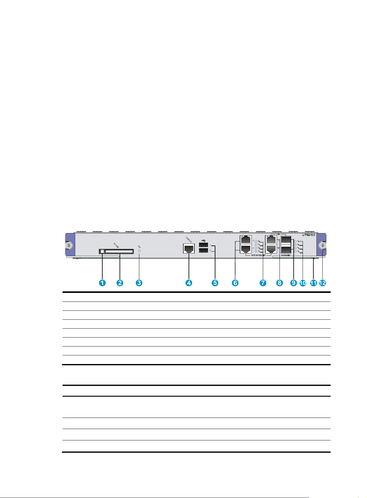
Figure 1 Front panel
1: CF card button
3: CF card LED (CFS) 4: Console port (CONSOLE)
5: USB ports (hardware reserved, software not support)
6: 10/100/1000BASE-T management Ethernet ports (GE1 and GE2)
7: Management Ethernet port LEDs
8: 10/100/1000BASE-T copper combo ports (GE3 and GE4)
9: 1000BASE-X fiber combo ports (SFP3 and SFP4) 10: Combo interface LEDs
11: Ejector lever 12: Captive screw
card slot (CF CARD)
Table 1 Card specifications
Item S
ecification
CF card
Dimensions (H × W × D) 40.1mm X399.2mm X498.8mm(1.58 × 15.72 × 19.64 in)
Power consumption 94.5W~125.2W
Weight 4.3 kg (9.48 lb)
One CF card slot, 256MB by default for the external CF card
256 MB, 512 MB, or 1 GB for an optional external CF card
i
Page 2

Manual version: 6PW101-20141219 BOM: 3123A0BY
p
p
Item Specification
Hot swapping Supported
• 1 console port
• 2 USB ports (reserved for future use)
• 2 pairs of combo ports, each pair containing the following ports:
Ports
Ambient temperature
Ambient relative humidity
Compatible device models H3C S12500 series switches
System software version See the release notes that come with the card.
{ 1 x 10/100/1000BASE-T copper port
{ 1 x 1000BASE-X SFP fiber port
You can use the combo enable { copper | fiber } command to activate either of
the ports in a pair. By default, the copper combo port is activated.
• Operating: 0°C to 45°C (32°F to 113°F)
• Not operating: –40°C to +70°C (–40°F to +158°F)
• Operating: 10% to 95%, noncondensing
• Non-operating: 5% to 95%, noncondensing
Table 2 Console port specifications
Item S
Connector RJ-45
Interface standard RS-232
Transmission baud rate 9600 bps (default) to 115200 bps
Transmission medium Asynchronous serial cable
Transmission distance ≤15 m (49.21 ft)
ecification
• Provides connection to an ASCII terminal.
Services
• Provides connection to the serial port of a local or remote PC (through a
pair of modems) that is running a terminal emulation program.
• Supports command line interface (CLI).
Table 3 10/100/1000BASE-T copper port specifications
Item S
Connector RJ-45
Interface standard 802.3, 802.3u, and 802.3ab
Interface type MDI/MDIX autosensing
Supported cable Category-5 (or above) twisted pair cable
ecification
Transmission distance 100 m (328.08 ft)
• 10 Mbps, half/full duplex
Operating mode
• 100 Mbps, half/full duplex
• 1000 Mbps, full duplex
ii
Page 3

Manual version: 6PW101-20141219 BOM: 3123A0BY
p
p
Table 4 1000BASE-X fiber port specifications
Item S
Transceiver module SFP
Connector LC
Interface standard 802.3, 802.3u, and 802.3ab
Operating mode 1000 Mbps, full duplex
ecification
Table 5 1000BASE-X SFP port specifications
Gigabit SFP module
SFP-GE-SX-MM850-A 850 nm LC
SFP-GE-LX-SM1310-A 1310 nm LC
SFP-GE-LH40-SM1310 1310 nm LC
SFP-GE-LH40-SM1550 1550 nm LC
SFP-GE-LH70-SM1550 1550 nm LC
Central
wavelength
Connector Cable specifications
62.5/125μm
multi-mode optical fiber
9/125 μm single-mode
optical fiber
9/125 μm single-mode
optical fiber
9/125 μm single-mode
optical fiber
9/125 μm single-mode
optical fiber
Maximum
transmission
distance
0.55 km (0.34 miles)
10 km (6.21 miles)
40 km (24.86 miles)
40 km (24.86 miles)
70 km (43.5 miles)
4 LEDs
SFP-GE-LH100-SM1550 1550 nm LC
9/125 μm single-mode
optical fiber
The card provides LEDs to show the operating status of the card and interfaces.
Table 6 LED description
LED Status Descri
Off The CF card is not present or cannot be identified.
The CF card is present and has passed the power on self test
(POST).
The system is reading the CF card data. Do not unplug the CF
card.
CF card(CFS)
GE/Combo copper
port
(LINK/ACT)
Steady green
Flashing green
Off No link is present on the port.
Steady green A link is present on the port.
Flashing yellow The port is sending or receiving data.
tion
100 km (62.14 miles)
iii
Page 4

Manual version: 6PW101-20141219 BOM: 3123A0BY
5 Installing and removing the card
CAUTION:
• Wear a well-grounded ESD wrist strap or ESD gloves before you install or remove the card.
• Do not touch the components on the PCB.
5.1 Installing the card
1. Remove the filler panel from the slot for the card at the front of the switch.
This example uses slot 7.
2. Place the card vertically with the surface-mounted components facing left. Pull the ejector levers
outward, and then gently push the card in along the slot guide rails until the card is in close contact
with the backplane.
3. Push the ejector levers inward.
4. Tighten the captive screws with a Phillips screwdriver to secure the card in the slot.
Figure 2 Installing the card
5.2 Removing the card
1. Use a Phillips screwdriver to loosen the captive screws at both sides of the card.
2. Pull the ejector levers at both sides of the card outward to separate it from the backplane, and then
pull the card along the guide rails to remove it from the chassis.
iv
Page 5

Manual version: 6PW101-20141219 BOM: 3123A0BY
3.
Place the card on an anti-static workbench with the surface-mounted components up. You can also
put it in an anti-static bag.
4. If you are not going to install a new card, install a filler panel to prevent dust and ensure good
ventilation in the switch.
6 Logging in to the card
The card uses an independent operating system. Before you can configure the card, you must log in to
the card by using one of the following methods:
• Log in from the switch's CLI through the oap connect command.
• Log in through the card's Web interface, console port, Telnet, or SNMP.
H3C recommends that you log in to the card from the switch's CLI the first time you access the card. This
section includes a procedure for logging in from the switch's CLI. For more information about other login
methods, see H3C SecBlade LB Module Configuration Guides.
To log in to the card from the switch's CLI, perform the following task in user view:
Task Command
Log in to the card through OAP.
7 Software upgrade
The card uses independent BootWare and system software images. You must upgrade the card software
separately from the switch software. To ensure a successful card upgrade, H3C recommends that you
upgrade the card through the card's console port or management Ethernet port. For more information
about software upgrade of the card, see the release notes that come with the card.
8 Obtaining documentation
To access the most up-to-date H3C product documentation on the World Wide Web
at http://www.h3c.com
1. Go to http://www.h3c.com/Technical_Documents, or click Technical Support & Documents >
Technical Documents on the top navigation bar at http://www.h3c.com
2. Click Security Products > H3C SecBlade Module to choose the desired product category and
model.
:
• In standalone mode:
oap connect slot slot-number
• In IRF mode:
oap connect chassis
chassis-number slot slot-number
Remarks
To return to the CLI interface of the
switch, press Ctrl+K.
.
Copyright © 2014 Hangzhou H3C Technologies Co., Ltd.
The information in this document is subject to change without notice.
v
 Loading...