

Page 1

H3C S7500 Series Ethernet Switches
Installation Manual
Hangzhou H3C Technologies Co., Ltd.
http://www.h3c.com
Manual Version: T2-08046P-20071205-C-1.02
Product Version: Release 3000/3100
Page 2

Copyright © 2006-2007, Hangzhou H3C Te chnologie s Co., Ltd .
All Rights Reserved
No part of this manual may be reproduced or transmitted in any form or by any means
without prior written consent of Hangzhou H3C Technologies Co., Ltd.
Trademarks
H3C, , Aolynk, , H3Care,
Neocean, NeoVTL, SecPro, SecPoint, SecEngine, SecPath, Comware, Secware,
Storware, NQA, VVG, V
HUASAN are trademarks of Hangzhou H3C Technologies Co., Ltd.
All other trademarks that may be mentioned in this manual are the property of their
respective owners.
Notice
The information in this document is subject to change without notice. Every effort has
been made in the preparation of this document to ensure accuracy of the content s, but
all statements, information, and recommendations in this document do not constitute
the warranty of any kind, express or implied.
To obtain the latest information, please access:
http://www. h3c.com
Technical Support
customer_service@h3c.com
http://www. h3c.com
, TOP G, , IRF, NetPilot,
2
G, VnG, PSPT, XGbus, N-Bus, TiGem, InnoVision and
Page 3

About This Manual
Related Documentation
In addition to this manual, each H3C S7500 Series Ethernet Switches documentation
set includes the following:
Manual Description
Organization
H3C S7500 Series Ethernet Switches Installation Manual is organized as follows:
H3C S7500 Series Ethernet Switches
Operation Manual
H3C S7500 Series Ethernet Switches
Command Manual
Chapter Contents
1 Product Overview
2 Line Processing Units
3 Installation Preparations
4 Hardware Installation
Guides the user to configure the
features supported by the S7500 series.
Elaborates on the commands for
configuring the S7500 series.
Introduces the characteristics of the
H3C S7500 Series Ethernet Switches.
Introduces LPUs of the H3C S7500
Series Ethernet Switches.
Introduces the preparations and
precautions for the H3C S7500 Series
Ethernet Switches installation.
Introduces the integrated equipment
installation and cable connection
(including connection of grounding
cables, power cables, and interface
cables, recommended cabling, and
cable binding) of the H3C S7500 Series
Ethernet Switches.
5 System Commissioning
6 Hardware Maintenance
Introduces the initial power-on startup
process of H3C S7500 Series Ethernet
Switches.
Introduces the installation and removal
of power module, card, fan tray, power
distribution box, delivered cable
management bracket, memory module,
and air filter of the H3C S7500 Series
Ethernet Switches.
Page 4
Chapter Contents
7 Software Maintenance
8 Troubleshooting
Introduces how to load and upgrade the
software of the H3C S7500 Series
Ethernet Switches.
Introduces how to troubleshoot the
configuration system, power system,
fans, and LPUs of the H3C S7500
Series Ethernet Switches.
Conventions
The manual uses the following conventions:
I. GUI conventions
Appendix A B68-22 Cabinet Installation
Appendix B N68 Cabinet Installation
Appendix C Lightning Protection
Appendix D AC Power Cables Used in
Different Countries
Convention Description
< >
Button names are inside angle brackets. For example, click
<OK>.
Introduces the installation of a B68-22
cabinet.
Introduces the installation of an N68-22
cabinet.
Introduces lightning protection of the
H3C S7500 Series Ethernet Switches.
Introduces the AC power cables used in
different countries, including 10A AC
power cables and 16A AC power cables.
Window names, menu items, data table and field names
[ ]
/
are inside square brackets. For example, pop up the [New
User] window.
Multi-level menus are separated by forward slashes. For
example, [File/Create/Folder].
II. Symbols
Convention Description
Means reader be extremely careful. Improper operation
Warning
Caution
Note Means a complementary description.
may cause bodily injury.
Means reader be careful. Improper operation may cause
data loss or damage to equipment.
Page 5

Environmental Protection
This product has been designed to comply with the requirements on environmental
protection. For the proper storage, use and disposal of this product, national laws and
regulations must be observed.
Page 6

Installation Manual
H3C S7500 Series Ethernet Switches Table of Contents
Table of Contents
Chapter 1 Product Overview........................................................................................................1-1
1.1 Introduction........................................................................................................................1-1
1.1.1 Introduction to S7500 Series Ethernet Switches.....................................................1-1
1.1.2 Introduction to Switching Engines...........................................................................1-2
1.2 Technical Specifications for SRPUs..................................................................................1-2
1.3 Salience III Series SRPUs................................................................................................. 1-3
1.3.1 Applicable Switch Models ....................................................................................... 1-4
1.3.2 Technical Specifications.......................................................................................... 1-4
1.3.3 Panel and LEDs ...................................................................................................... 1-5
1.3.4 Ports........................................................................................................................ 1-6
1.3.5 System Status LEDs ............................................................................................. 1-10
1.3.6 RESET Button.......................................................................................................1-11
1.4 Compatibility Matrix Between SRPU, Chassis and LPU.................................................1-11
1.4.1 Compatibility Matrix Between SRPU and Chassis................................................ 1-11
1.4.2 Compatibility Matrix Between SRPU and LPU......................................................1-12
1.5 Physical Description of the S7500 Series........................................................................ 1-12
1.5.1 Chassis and Slots .................................................................................................1-12
1.5.2 Color of Board Edges............................................................................................1-17
1.5.3 Backplane..............................................................................................................1-18
1.5.4 Power Supply........................................................................................................ 1-19
1.5.5 PoE Power Supply................................................................................................1-22
1.5.6 Fan Tray................................................................................................................ 1-23
1.6 Technical Specifications for the S7500 Series................................................................ 1-25
1.7 Compatibility Matrix Between Software Feature, SRPU and LPU ..................................1-26
i
Page 7

Installation Manual
H3C S7500 Series Ethernet Switches Chapter 1 Product Overview
Chapter 1 Product Overview
1.1 Introduction
1.1.1 Introduction to S7500 Series Ethernet Switches
H3C S7500 Series Ethernet Switches (hereinaf ter ref erred to as th e S7500 seri es) are
modular, large-capacity L2/L3 Ethernet switches that support wire-speed forwarding.
The S7500 series are designed for IP metropolitan area networks (MANs), large
enterprise networks, and campus networks.
Together with Huawei MA5200 Ethernet Access Management Systems, H3C
S3100/S3600/S5600/S9500 Series Ethernet Switches, and H3C series routers, the
S7500 series can provide comprehensive networking solutions for MANs and
enterprise networks.
Figure 1-1 S7500 series in MAN
The S7500 series support AC and DC power supply redundancy, and now include the
models S7502, S7503, S7506, and S7506R.
z The S7502 provides one switching & routing processing unit (SRPU) slot and one
line processing unit (LPU) slot. Both the SRPU and LPU can provide high-density
service ports.
z The S7503 provides one SRPU slot and three LPU slots.
z The S7506 provides one SRPU slot and six LPU slots.
z The S7506R provides two SRPU slots for redundancy backup and six LPU slots.
1-1
Page 8

Installation Manual
H3C S7500 Series Ethernet Switches Chapter 1 Product Overview
Note:
z Refer to H3C S7502 Ethernet Switch Installation Manual for detailed information
about the S7502.
z In the later chapters, only the S7503, S7506, and S7506R are involved.
1.1.2 Introduction to Switching Engines
Switching engines, also known as SRPUs, are the core of the S7500 series, and
include the following models:
z Salience III (LS81SRPG)
z Salience III Plus (LS81SRPG1)
z Salience III Edge (LS81SRPG3)
An SRPU generally has the following functions:
z L2 and L3 data forwarding between LPUs
z Route calculation
z LPU monitoring
z Processing of monitoring signals of components such as the system power and
fans
Salience III series SRPUs provide a high packet forwarding rate and switching capacity .
Each SRPU provides four 1000Base-X SFP ports (only for Salience III and Salience III
Edge) and one hot-swappable CF card port. The CF card stores the log and host
version to facilitate online software upgrade.
1.2 Technical Specifications for SRPUs
Table 1-1 Technical specifications for SRPUs
Item Salience III Salience III Plus Salience III Edge
Switching capacity 384 Gbps
Packet forwarding
rate
198 Mpps
Number of VLANs 4 K 4 K 4 K
MAC address table
size
32 K
IP address table size 64 K
[1]
768 Gbps
[1]
432 Mpps
[2]
32 K
[3]
64 K
[2]
[3]
[1]
96 Gbps
[1]
72 Mpps
32 K
64 K
[1]: This is the switching capacity when load sharing is implemented by configuring two
Salience III/Salience III plus engines on the S7506R.
1-2
Page 9
Installation Manual
H3C S7500 Series Ethernet Switches Chapter 1 Product Overview
[2]: Extendable.
[3]: Extendable up to 256 K.
1.3 Salience III Series SRPUs
Salience III series SRPUs include:
z Salience III: If load sharing is implemented on the S7506R, the switching capacity
can be up to 384 Gbps. It provides an XG high speed bus, supporting LPUs
applying an XG high speed bus.
z Salience III Plus: If load sharing is implemented on the S7506R, the switching
capacity can be up to 768 Gbps. It provides XG high speed bus, supporting LPUs
applying an XG high speed bus.
z Salience III Edge: The switching capacity is 96 Gbps.
The Salience III series SRPUs provide one console port, one 10Base-T /100Base-TX
port, four 1000Base-X-SFP ports (only for Salience III and Salience III Edge), and one
port for a hot-swappable CF card, which stores the host version to facilitate the online
software upgrade.
Note:
Both Salience III and Salience III Plus provide an XG high speed bus and support the
LPUs that adopt an XG high speed bus. However, they provide the high speed bus in
different ways. If a Salience III SRPU is used, it can provide the XG high speed bus only
for the LPUs in the last two slots of the switch. If a Salience III Plus SRPU is used, it can
provide the XG high speed bus for LPUs in all slots.
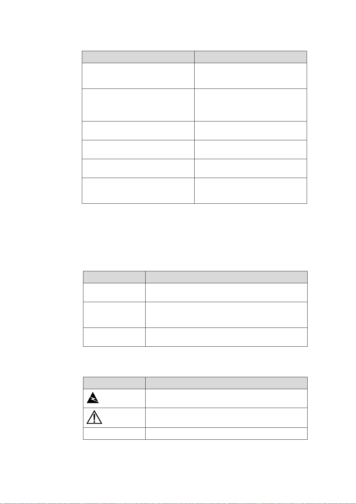
The following figures show the appearance of these three SRPU models.
Figure 1-2 Salience III
1-3
Page 10
Installation Manual
H3C S7500 Series Ethernet Switches Chapter 1 Product Overview
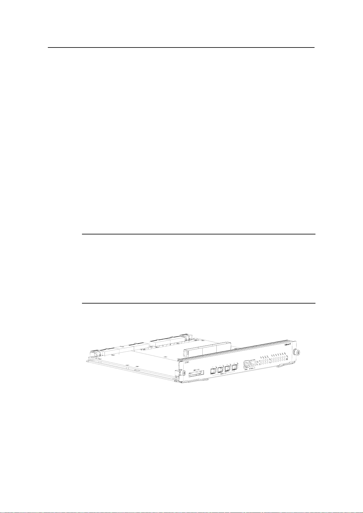
Figure 1-3 Salience III Plus
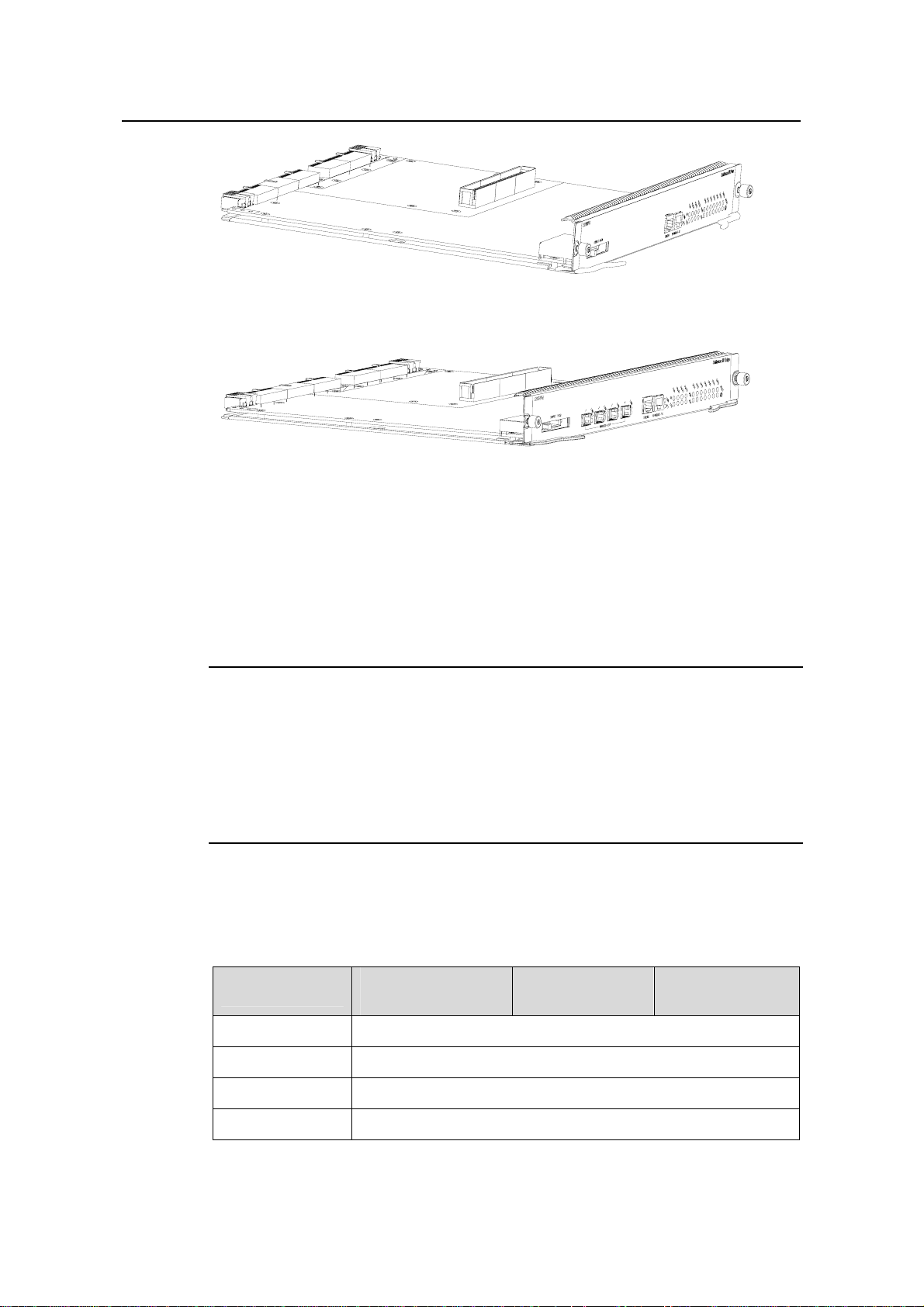
Figure 1-4 Salience III Edge
1.3.1 Applicable Switch Models
z S7503 Ethernet Switch
z S7506 Ethernet Switch
z S7506R Ethernet Switch
Note:
z When two Salience III or Salience III Edge engines are used in an S7506R XGbus
chassis as the main and standby SRPUs, the first two SFP ports on both the active
and standby SRPUs can work in a redundancy mode so that the services will not
interrupted (the first two SFP ports are also active) during an active-standby
switchover.
1.3.2 Technical Specifications
Table 1-2 Technical specifications for Salience III series SRPUs
Item
Salience III
(LS81SRPG)
Salience III Plus
(LS81SRPG1)
Salience III Edge
(LS81SRPG3)
CPU MPC8245, 300 MHz
Boot ROM 512 KB
Flash memory 32 MB
SDRAM 256 MB
1-4
Page 11

Installation Manual
H3C S7500 Series Ethernet Switches Chapter 1 Product Overview
Item
Salience III
(LS81SRPG)
Salience III Plus
(LS81SRPG1)
Salience III Edge
(LS81SRPG3)
Dimensions (H x
W x D)
Number of ports
Max power
consumption
Note:
The dimensions here refer to those of a board with ejector levers.
1.3.3 Panel and LEDs
45.1 × 376.7 × 354.5 mm (1.8 × 14.8 × 14 in.)
z One console port, supporting local configuration
management or remote configuration management through
dialup connection
z One 10Base-T/100Base-TX port for upgrade and network
management
z One port for a hot-swappable CF card
Four
1000Base-X-SFP
optical ports
—
Four
1000Base-X-SFP
optical ports
80 W
You can find one CF card port, four 1000Base-X-SFP ports (only for Salience III and
Salience III Edge), one console port, one 10Base-T/100Base-TX port, system status
LEDs, and one RESET button on the panel of a Salience III Series SRPU, as shown in
Figure 1-5.
1-5
Page 12

Installation Manual
H3C S7500 Series Ethernet Switches Chapter 1 Product Overview
(1) (2) (3) (5) (6) (7) (8) (9)
(21)(22)
(1) SFP port number (2) SFP port (Gigabit)
(3) Console port (4) Management Ethernet port
(5) LINK LED of the management Ethernet
port
(7) RUN LED of LPU (8) ALM LED of LPU
(9) RUN LED of SRPU (10) ALM LED of SRPU
(11) Silkscreen (12) Captive screw
(13) SRPU edge (pink) (14) RESET button
(15) Ejector lever (16) OK LED of the power
(17) FAIL LED of the power (18) OK LED of the fan
(19) FAIL LED of the fan (20) SFP port status LED
(21) CF card port (22) Button for ejecting the CF card
(20)
(4) (10)
(16)(17)(18)(19)
(6) ACT LED of the management Ethernet
port
Figure 1-5 Panel of a Salience III Series SRPU (LS81SRPG)
(14)
(11)
(12)
(13)(15)
Note:
z The panel of a Salience III Edge SRPU is the same as that of a Salience III SRPU
z The panel of a Salience III Plus SRPU is the same as that of a Salience III SRPU
1.3.4 Ports
I. CF card port
The port supports standard CF cards. The CF card stores the host version to facilitate
the online software upgrade.
except the board name and board silk-screen.
except that it has a different board name and board silk-screen and provides no SFP
port.
1-6
Page 13

Installation Manual
H3C S7500 Series Ethernet Switches Chapter 1 Product Overview
Note:
z Do not remove the CF card when it is performing a read or write operation.
z Do not disconnect the power supply when the CF card is performing a read or write
operation.
z Execute the umount command in user view before removing the CF card.
II. Console port
The console port uses an RJ-45 connector and common asynchronous serial cable to
connect to a terminal computer for local debugging, configuration, maintenance,
management, and program loading, or connect to a Modem for remote system
debugging, configuration, maintenance, and management.
Table 1-3 Technical specifications for the console port
Item Specification
Connector type RJ-45
Number of ports 1
Compliant standard Asynchronous EIA/TIA-232
Baud rate ≤ 115,200 bps, defaulting to 9,600 bps
Transmission distance ≤ 15 m (49 ft)
z Connected to the character terminal
Function and service
z Connected to a serial port of a local PC or
remote PC through a pair of Modems and run
the terminal emulation on the PC
III. Management Ethernet port (10Base-T/100Base-TX)
The port uses an RJ-45 connector to connect to a computer for program loading and
system debugging, or to a remote network management workstation for remote system
management.
Table 1-4 Technical specifications for the management Ethernet port
Item Description
Connector type RJ-45
Number of ports 1
Port speed
Transmission medium and maximum
transmission distance
1-7
z 10/100 Mbps, half-/full-duplex
z MDI/MDI-X auto-sensing
Category-5 twisted pair with a maximum
transmission distance of 100 m (328 ft)
Page 14
Installation Manual
H3C S7500 Series Ethernet Switches Chapter 1 Product Overview
Item Description
Function and service
Used for the switch’s software upgrade
and network management
The following table describes the port status LEDs.
Table 1-5 10Base-T/100Base-TX port LED state description
LED State Description
OFF No link is present.
LINK
ON A link is present.
OFF No data is being transmitted or received.
ACT
Blinking Data is being transmitted or received.
Note:
z The management Ethernet port can go up only when the physical connection is
normal (the LINK LED is ON) and an IP address is configured.
z The management Ethernet port can perform auto-negotiation when it is up.
IV. 1000Base-X-SFP ports (only for Salience III and Salience III Edge)
Salience III series (only Salience III and Salience III Edge) SRPUs each provide four
1000 Mbps full-duplex SFP ports.
Table 1-6 describes the cables used for the
1000Base-X-SFP ports.
Table 1-6 Cables for 1000Base-X-SFP ports
Maximum
transmission
distance
550 m (1,804
ft)
275 m (902 ft)
SFP module
SFP-GE-SX-M
M850-A
Central
wavelength
Connector Matching cable
850 nm LC
50 µm/125 µm
multimode optical
fiber
62.5 µm/125 µm
multimode optical
fiber
SFP-GE-LX-S
M1310-A
SFP-GE-LH40
-SM1310
1,310 nm LC
9 µm/125 µm
single-mode
optical fiber
10 km (6 mi)
40 km (about
25 mi)
1-8
Page 15

Installation Manual
H3C S7500 Series Ethernet Switches Chapter 1 Product Overview
Maximum
transmission
distance
SFP module
Central
wavelength
Connector Matching cable
SFP-GE-LH40
-SM1550
SFP-GE-LH70
-SM1550
SFP-GE-LH10
0-SM1550
SFP-GE-LH70
-SM1470-CW
SFP-GE-LH70
-SM1490-CW
SFP-GE-LH70
-SM1510-CW
SFP-GE-LH70
-SM1530-CW
SFP-GE-LH70
-SM1550-CW
1,550 nm LC
1,470 nm LC
1,490 nm LC
1,510 nm LC
1,530 nm LC
1,550 nm LC
9 µm/125 µm
single-mode
optical fiber
9 µm/125 µm
single-mode
optical fiber
9 µm/125 µm
single-mode
optical fiber
9 µm/125 µm
single-mode
optical fiber
9 µm/125 µm
single-mode
optical fiber
9 µm/125 µm
single-mode
optical fiber
40 km (about
25 mi)
70 km (43 mi)
100 km (62
mi)
70 km (43 mi)
70 km (43 mi)
70 km (43 mi)
70 km (43 mi)
70 km (43 mi)
SFP-GE-LH70
-SM1570-CW
SFP-GE-LH70
-SM1590-CW
SFP-GE-LH70
-SM1610-CW
1,570 nm LC
1,590 nm LC
1,610 nm LC
9 µm/125 µm
single-mode
optical fiber
9 µm/125 µm
single-mode
optical fiber
9 µm/125 µm
single-mode
optical fiber
70 km (43 mi)
70 km (43 mi)
70 km (43 mi)
SFP-GE-T — RJ-45 — 100 m (328 ft)
Table 1-7 describes the 1000Base-X-SFP port status LED.
Table 1-7 Description of the 1000Base-X-SFP port status LED
LED State Description
LINK/ACT
OFF
ON
Blinking
No link is present.
A link is present
Data is being transmitted or received.
1-9
Page 16

Installation Manual
H3C S7500 Series Ethernet Switches Chapter 1 Product Overview
1.3.5 System Status LEDs
Note:
When two SRPUs are configured on an S7506R Ethernet switch, all the other LEDs on
the standby SRPU are constantly OFF except the LEDs of the SRPG.
I. Board LEDs
SRPG: The LEDs of the SRPG show the status of the SRPU.
LPU1, LPU2, LPU3 (LPU4, LPU5, LPU6): The LEDs of these LPUs respectively show
the status of three LPUs (for the S7503), or six LPUs (for the S7506 or S7506R).
Table 1-8 Description of board LEDs
LED Description
RUN (Green)
ALM (Red)
z ON or OFF: The board is faulty or the board is not in position.
z Blinking (0.5 Hz): The board operates normally.
z OFF: The board operates normally or the board is not in
position.
z ON: The board is faulty.
Note:
If the RUN LED blinks fast, the board is booting but does not operate normally. During
the initialization of the system, the ALM LED will be on for a while, but this does not
mean that the board is faulty.
II. Power LEDs (PWR1, PWR2 and PWR3)
PWR1, PWR2 and PWR3: The LEDs of the PWR1, PWR2 and PWR3 respectively
show the status of the three (AC or DC) power modules.
Table 1-9 Description of the power LEDs
LED Description
OK (Green)
FAIL (Red)
z ON: The power module operates normally.
z OFF: The power module is faulty or not in position.
z ON: The power module is faulty.
z OFF: The power module operates normally or is not in position.
1-10
Page 17
Installation Manual
H3C S7500 Series Ethernet Switches Chapter 1 Product Overview
Note:
If the FAIL LED on the S7503 is on, it is also possible that the power module is in
position but the power switch is not turned on.
III. Fan tray LEDs (FAN)
FAN: The LEDs of the fan tray show the status of the fan tray.
Table 1-10 Description of fan tray LEDs
LED State description
OK (Green)
FAIL (Red)
ON: The fan tray operates normally.
OFF: The fan tray is faulty or the fan tray is not in position.
ON: The fan tray is faulty or the fan tray is not in position.
OFF: The fan tray operates normally.
1.3.6 RESET Button
z If a switch is equipped with one SRPU, the switch will be reset after you press the
RESET button.
z If the S7506R is equipped with two SRPUs, the active SRRU is reset and the
standby SRPU immediately becomes the active SRPU after you press the RES ET
button.
1.4 Compatibility Matrix Between SRPU, Chassis and LPU
1.4.1 Compatibility Matrix Between SRPU and Chassis
Table 1-11 Compatibility matrix between SRPU and chassis
SRPU
Chassis
Salience III Salience III Plus Salience III Edge
S7503 XGbus √ √ √
S7506 XGbus √ √ √
S7506R XGbus √ √ √
1-11
Page 18

Installation Manual
H3C S7500 Series Ethernet Switches Chapter 1 Product Overview
1.4.2 Compatibility Matrix Between SRPU and LPU
Table 1-12 Compatibility Between SRPU and LPU
SRPU
LPU
LS81FT48E √ √ √
LS81FT48F √ √ √
LS81FP48 √ √ √
LS81GT8UE √ — √
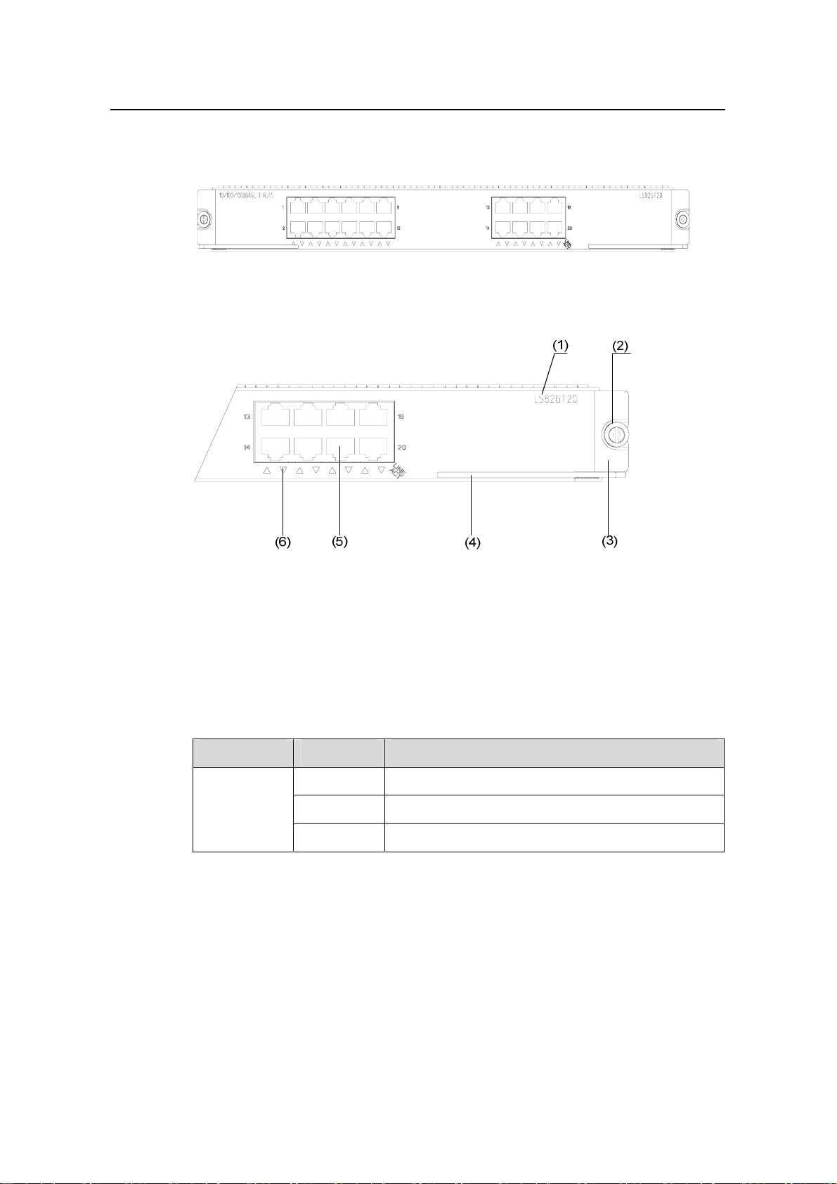
LS82GT20 √ √ √
LS82GT20A √ √ √
LS81GT48 √ √ √
LS81GT48A √ √ √
LS81GT48B √ √ LS81T12P √ √ √
LS81T12PE √ √ √
LS81T16P √ √ —
LS81T32P √ √ —
Salience III Salience III Plus Salience III Edge
LS81P12T √ √ √
LS81P12TE √ √ √
LS81GP8UB √ — √
LS82GP20 √ √ √
LS82GP20A √ √ √
LS81GP48 √ √ —
LS81TGX1C √ √ √
LS81TGX2 √ √ —
LS81TGX4 √ √ —
LS81VSNP √ √ —
1.5 Physical Description of the S7500 Series
1.5.1 Chassis and Slots
The integrated chassis of the S7500 series consists of a board area, fan area, power
supply area, and power distribution area.
1-12
Page 19
Installation Manual
H3C S7500 Series Ethernet Switches Chapter 1 Product Overview
XGbus is silkscreened on the S7500 series chassis (hereinafter referred to as the
S7500 XGbus). The backplane of the S7500 series supports XG high speed bus, and
thus can provide even higher switching capacity.
Depending on the input power, the chassis of the S7500 series can be divided into AC
chassis and DC chassis.
S7503:
z S7503-AC-XG-PoE: PoE-capable S7503 XGbus AC chassis
z S7503-DC-XG-PoE: PoE-capable S7503 XGbus AC chassis
S7506:
z S7506-AC-XG-PoE: PoE-capable S7506 XGbus AC chassis
z S7506-DC-XG-PoE: PoE-capable S7506 XGbus DC chassis
S7506R:
z S7506R-AC-XG-PoE: PoE-capable S7506R XGbus AC chassis
z S7506R-DC-XG-PoE: PoE-capable S7506R XGbus DC chassis
Note:
z The S7500 series provide power to remote powered devices (PD) such as IP
phones and WLAN wireless access points (AP) by using PoE-capable cards and
power sourcing equipment (PSE).
z The backplane, SRPU, power module, and fan tray are necessary components of
the S7500 series.
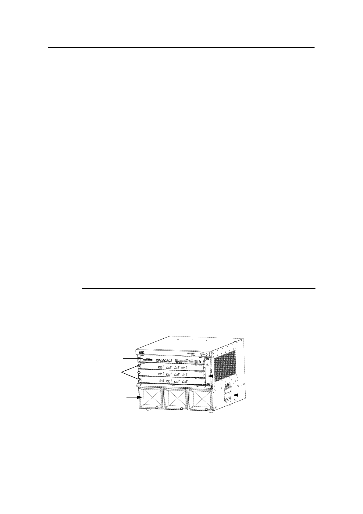
I. S7503
Figure 1-6 shows the chassis and slots of the S7503.
主控板
主控板
SRPU
SRPU
LPUs
LPUs
业务板
业务板
Power module
Power module
电源模块
电源模块
Fan tray
Fan tray
风扇框
风扇框
机箱拉手
机箱拉手
Chassis handle
Chassis handle
Figure 1-6 Chassis of the S7503
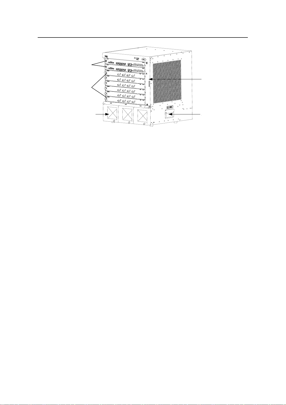
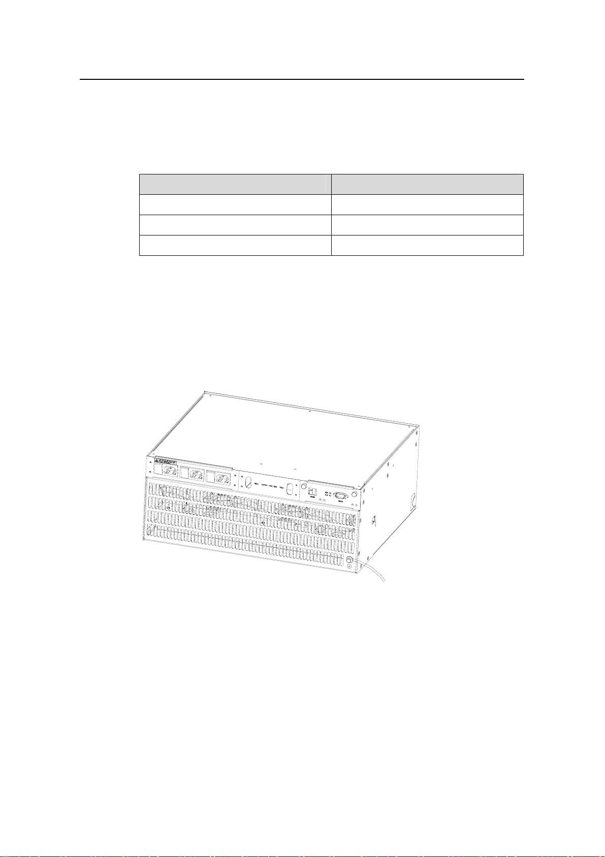
Figure 1-7 shows the chassis back of the S7503.
1-13
Page 20

Installation Manual
H3C S7500 Series Ethernet Switches Chapter 1 Product Overview
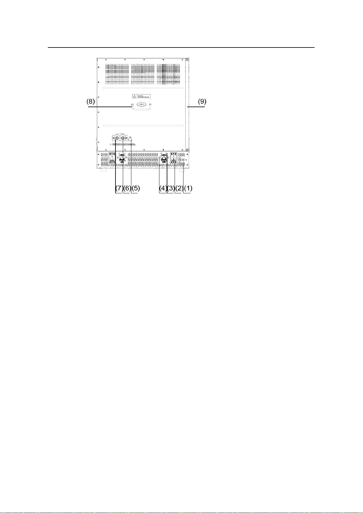
(1) Grounding screw (2) Power switch of power distribution box
(3) Bail latch (4) Socket of AC power distribution box
(5) COM port (PSE monitoring port) (6) RTN (+) terminal of the Po E power input:
(7) NEG (-) terminal of the PoE power input (8) Handle on the rear panel
(9) Air filter
Figure 1-7 Rear view of the S7503 chassis (S7503-AC-XG-PoE chassis in the
example)
Caution:
z The handle on the rear panel is used for removing or installing the rear panel of the
switch. It does not bear the weight of the whole switch. Thus, do not hold this handle
when handling or moving the switch. The same is true of the handles on the rear
panels of all the S7500 series.
z A filler panel is installed in the power module slot marked with NULL in Figure 1-6
and no power module can be inserted into it.
Each area is hot-swappable.
z In the board area, there are four horizontal slots. The t opmost slot is for a required
SRPU and the other three are for optional LPUs.
z The fan area is on the right of the chassis. The fan tray slot is vertical.
z The power supply area is at the bottom of the chassis. The power modules work in
1+1 redundancy mode and they support dual AC or DC power supply. You can
select either AC power supply or DC power supply as required.
1-14
Page 21
Installation Manual
手
手
H3C S7500 Series Ethernet Switches Chapter 1 Product Overview
z The power distribution area is at the chassis bottom near to the rear panel. There
is an AC power distribution box for AC power input or a DC powe r distrib ution box
for DC power input.
z There are a –48 VDC power input terminal and a COM port (PoE management
Ethernet port) on the back of the PoE-capable S7503 XGbus chassis.
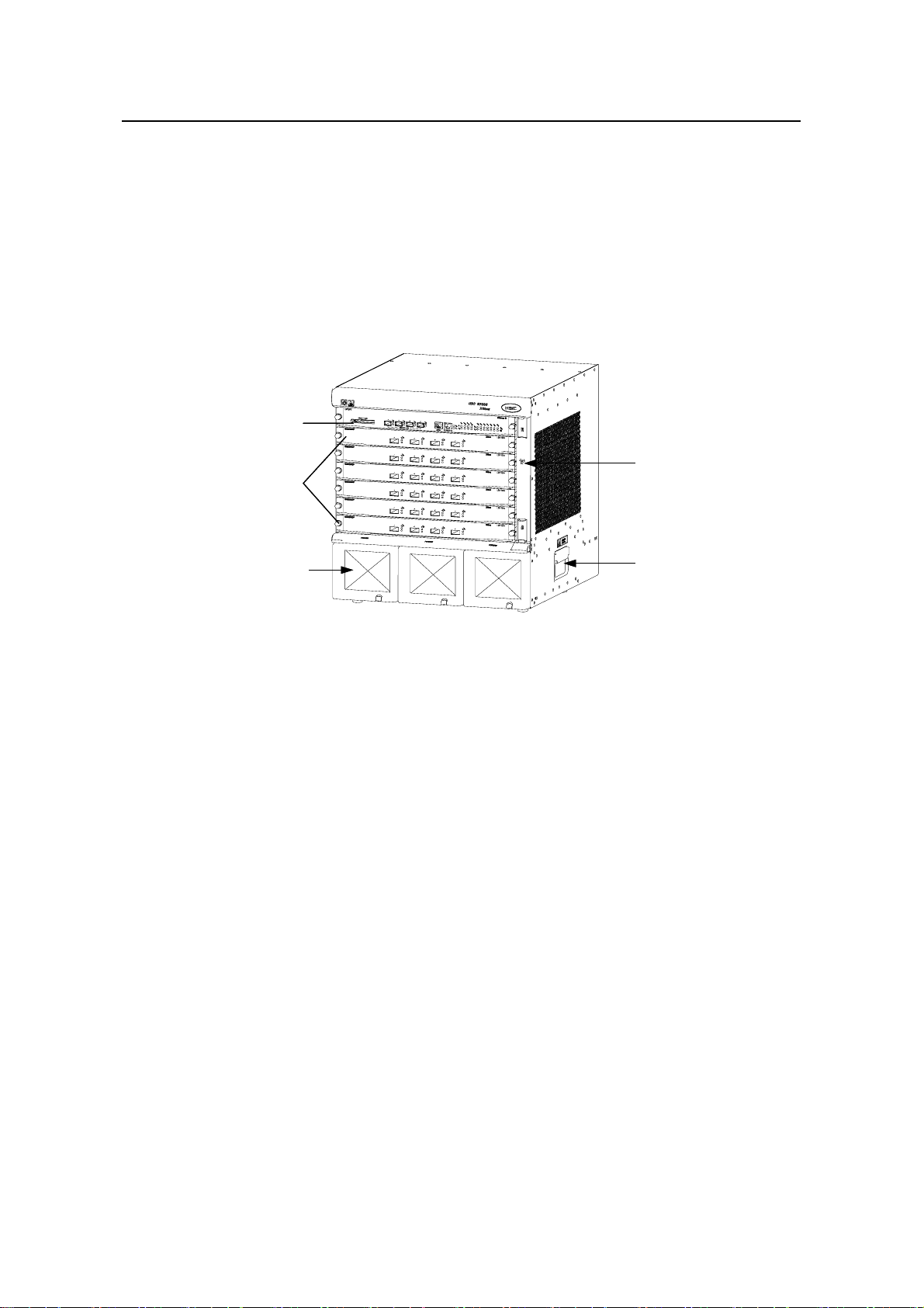
II. S7506
Figure 1-8 shows the chassis and slots of the S7506.
SRPU
SRPU
主控板
主控板
风扇框
风扇框
Fan tray
LPUs
LPUs
业务板
业务板
Fan tray
电源模块
电源模块
Power module
Power module
Figure 1-8 Chassis of the S7506
Figure 1-9 shows the chassis back of the S7506.
机箱拉
机箱拉
Ch as sis handle
Ch as sis handle
1-15
Page 22
Installation Manual
H3C S7500 Series Ethernet Switches Chapter 1 Product Overview
(1) Grounding screw (2) Power switch
(3) Bail latch (4) Power socket
(5) COM port (PSE monitoring port) (6) RTN (+) terminal of PoE power input
(7) NEG (-) terminal of PoE power input (8) Handle on the rear panel
(9) Air filter
Figure 1-9 Rear view of the S7506 chassis (S7506-AC-XG-PoE chassis in the
example)
Each area is hot-swappable.
z The board area contains seven horizontal slots. The topmost slot top is for a
required SRPU and the other six slots for optional LPUs.
z The fan area is on the right of a chassis. The fan tray slot is vertical.
z The power supply area is at the bottom of the chassis and contains three power
module slots to implement 2+1 redundancy. You can select AC po wer modules for
AC power input or DC power modules for DC power input as required.
z The power distribution area is at the chassis bottom near to the back panel. There
is an AC power distribution box for AC power input or a DC powe r distrib ution box
for DC power input.
z There are a –48 VDC power input terminal and a COM port (PoE management
port) on the back of the PoE-capable S7506 XGbus chassis.
III. S7506R
Figure 1-10 shows the chassis and slots of the S7506R.
1-16
Page 23
Installation Manual
H3C S7500 Series Ethernet Switches Chapter 1 Product Overview
SRPUs
SRPUs
主控板
主控板
风扇框
风扇框
Fan tray
Fan tray
业务板
业务板
LPUs
LPUs
Power module
Power module
机箱拉手电源模块
机箱拉手电源模块
Ch assis handle
Ch assis handle
Figure 1-10 Chassis of the S7506R
The rear panel of the chassis of the S7506R is similar to that of the S7506. For the
layout, see
Figure 1-9.
Each area is hot-swappable.
z In the board area, there are eight horizontal slots. The topmost two slots are for
required SRPUs. The S7506R provides SRPU redundancy backup. The other six
are for optional LPUs.
z The fan area is on the right of a chassis. The fan tray slot is vertical.
z The power module area is at the bottom of the chassis and contains three power
module slots to implement 2+1 redundancy. You can select AC po wer modules for
AC power input or DC power modules for DC power input as required.
z The power distribution area is at the chassis bottom near to the back panel. There
is an AC power distribution box for AC power input or a DC powe r distrib ution box
for DC power input.
z There are a –48 VDC power input terminal and a COM port (PoE management
port) on the back of the PoE-capable S706R chassis.
1.5.2 Color of Board Edges
z The boards that can only serve as SRPUs of the S7503/S7506/S7506R have pink
edges.
z The boards that can only serve as LPUs of the S7503/S7506/S7506R have purple
edges.
z The boards that can not only serve as SPRUs of the S7502, but also LPUs of the
S7503/S7506/S7506R have green edges.
1-17
Page 24
Installation Manual
H3C S7500 Series Ethernet Switches Chapter 1 Product Overview
Note:
For the S7500 series, a board with pink edges can be inserted only into a slot indicated
by a pink area on the fan tray, and a board with purple or green edges can be inserted
only into a slot indicated by a purple area.
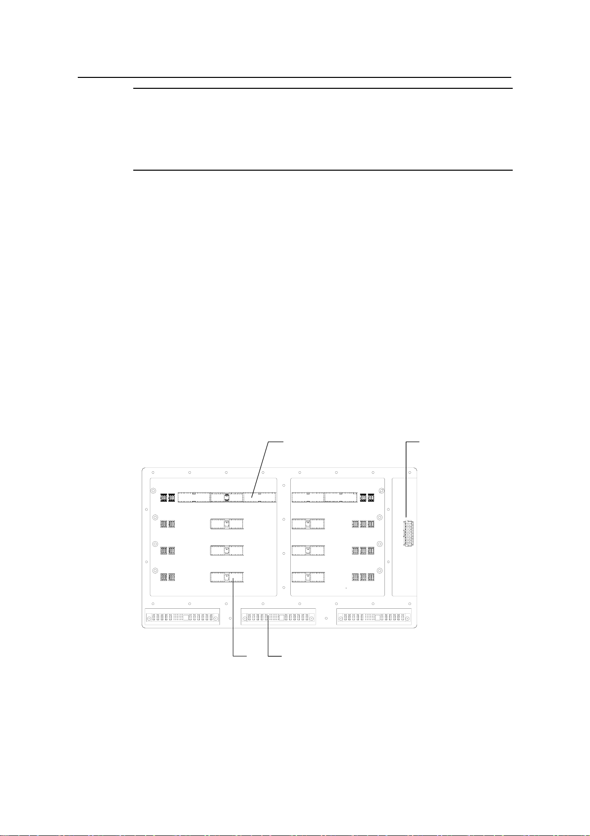
1.5.3 Backplane
The backplane of the S7500 series is located in the integrated chassis and imple ment s
high-speed data exchange and management & control signal exchange between
SRPUs and LPUs. The backplane in the S7500 chassi s supports XG high speed bus.
The backplane has the following functions:
z Providing communication channels for signal exchange between boards
z Supporting online insertion and removal of boards
z Supporting slot auto-identification
z Connecting to the power modules to provide distributed power supply for LPUs
and SRPUs
z Connecting to fan tray and power monitoring signal cables
z Supporting switchover between the active and standby SRPUs (only for the
S7506R)
(1) (2)
(4)
(1) SRPU socket (2) Fan tray socket
(3) PWR socket (4) LPU socket
(3)
Figure 1-11 Backplane of the S7503
1-18
Page 25
Installation Manual
H3C S7500 Series Ethernet Switches Chapter 1 Product Overview
1.5.4 Power Supply
Note:
z The S7500 series support AC and DC power supply. You can select AC or DC
power modules as required.
z Only one power module can ensure the normal operation of the S7503. However,
the S7503 provides two power module slots to implem ent 1+1 redundancy backup.
z Two power modules can ensure the normal operation of the S7506 or the S7506R.
However, the S7506 or S7506R provides three power module slots to implement
2+1 redundancy backup.
z The power modules of the S7500 series are hot swappable.
z Although the S7503 provides three power module slots, no power module can be
inserted in the power module slot marked with NULL. Therefore, the PWR3 LED is
always off.
AC power modules and DC power modules of the S7500 series must
z Have exactly the same dimensions and ports.
z Have exactly the same type of output connector in the same position.
z Not be inserted into one switch.
z Use their corresponding power distribution boxes.
(2)(3)
(1) Captive screw (2) Front shell of power module
(3) Air filter
(1)
Figure 1-12 Power module
1-19
Page 26
Installation Manual
H3C S7500 Series Ethernet Switches Chapter 1 Product Overview
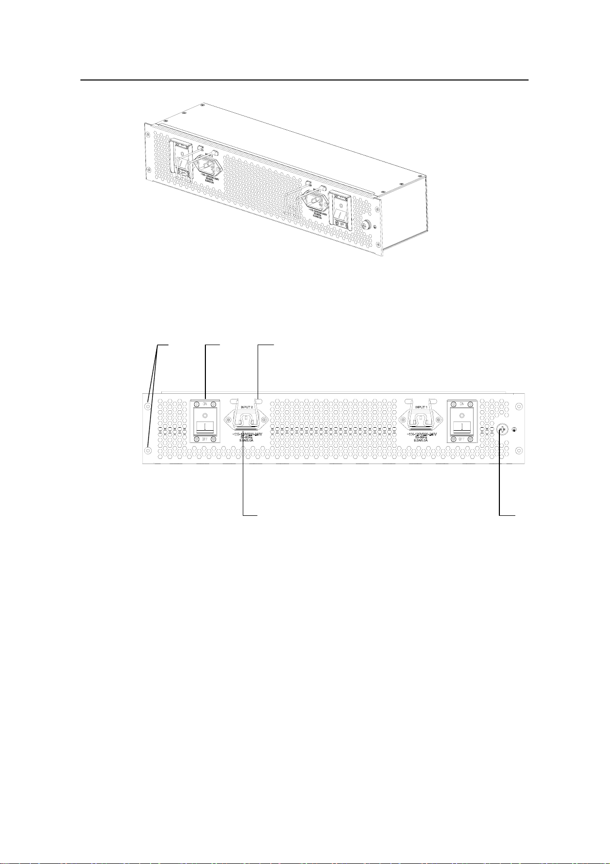
Figure 1-13 Power distribution box (dual-input dual-switch AC power distribution box in
the example)
(1) (2) (3)
(5)
(1) Screw holes (2) Power switch
(3) Bail latch (4) Grounding screw
(5) Power socket
(4)
Figure 1-14 Rear view of power distribution box (dual-input dual-switch AC power
distribution box in the example)
I. Introduction to power distribution box
The power distribution box is mainly used for filtering, current make/break, an d cu rrent
shunt. The AC power distribution box and DC power distribution box have the same
dimensions.
1) S7503
z The DC power distribution box of the S7503 supports two power inputs, each of
which has a separate power switch. One input can only support the normal
operation of the corresponding DC power module. Only when two inputs are
connected, the two DC power modules can work in 1+1 redundancy mode. Whe n
1-20
Page 27

Installation Manual
H3C S7500 Series Ethernet Switches Chapter 1 Product Overview
two DC power modules are equipped but only one input is connected, the SRPU
displays alarm information for the unsupplied module.
z The AC power distribution box of the S7503 supports two power inputs, each of
which has a separate power switch. One input can only maintain the normal
operation of the corresponding AC power module. Only when the two inputs are
connected, the two AC power modules can work in 1+1 redundancy mode. When
two AC power modules are equipped but only one input is connected, the SRPU
displays alarm information for the unsupplied module.
2) S7506 and S7506R
z The DC power distribution box of the S7506 and S7506R supports two power
inputs, each of which has a separate power switch. Either of the two inputs can
maintain the normal operation of the three DC power modules at the same time.
When one input is connected, the three DC power modules can work in 2+1
redundancy mode. When two inputs are connected, the DC powe r inputs can work
in 1+1 redundancy mode.
z The AC power distribution box of the S7506 and S7506R supports two power
inputs, each of which has a separate power switch. Either of the two inputs can
maintain the normal operation of the three AC power modules at the same time.
When only one input is connected, the three AC power modules can work in 2+1
redundancy mode. When two inputs are connected, th e AC power inputs can work
in 1+1 redundancy mode.
Table 1-13 AC power distribution boxes of S7506 and S7506R
AC power distribution
box
110-120V/220-240V,
dual-input, dual-switch
Input voltage range Applicable chassis
110-120 V/220-240 VAC;
50 Hz or 60 Hz; 9.0A/5.0 A
S7500-AC-XG-PoE
II. AC power module
For AC power supply, you should use AC power modules and AC power distribution
boxes.
Table 1-14 Specifications for AC power module
Item Specification
Rated voltage range 100 VAC to 240 VAC, 50 Hz or 60 Hz
Input voltage range 90 VAC to 264 VAC, 50 Hz or 60 Hz
Maximum output power
450 W
1-21
Page 28
Installation Manual
H3C S7500 Series Ethernet Switches Chapter 1 Product Overview
III. DC power module
For DC power supply, you should use DC power modules and DC power distribution
boxes.
Table 1-15 Specifications for DC power module
Item Specification
Rated voltage range –48 VDC to –60 VDC
Input voltage range –36 VDC to –72 VDC
Maximum output power
1.5.5 PoE Power Supply
The S7500 series support power-over-Ethernet (PoE). Equipped with power sourcing
equipment (PSE) and PoE-capable boards, the S7500 series can provide –48 VDC
power to remote powered devices (PDs) such as IP Phones, WLAN APs, and network
cameras through twisted pairs. Choose a chassis that supports PoE if PoE is needed.
450 W
Figure 1-15 Power sourcing equipment–PSE2500-A3
1-22
Page 29
Installation Manual
H3C S7500 Series Ethernet Switches Chapter 1 Product Overview
Note:
z The S7500 series support a maximum PoE input power of 2400 W.
z If the PSE2500-A3 is used, one rectifier can supply 1250 W, two 2400 W, and three
in 2+1 redundancy mode also 2400 W at an input voltage of 100 to 140 VAC. One
rectifier can supply 2500 W at a voltage of 200 to 240 VAC and two power modul es
are required for redundancy backup.
z The S7500 series provide power through Ethernet electrical ports on the
PoE-capable cards, with a maximum PoE distance of 100 m (328 ft.).
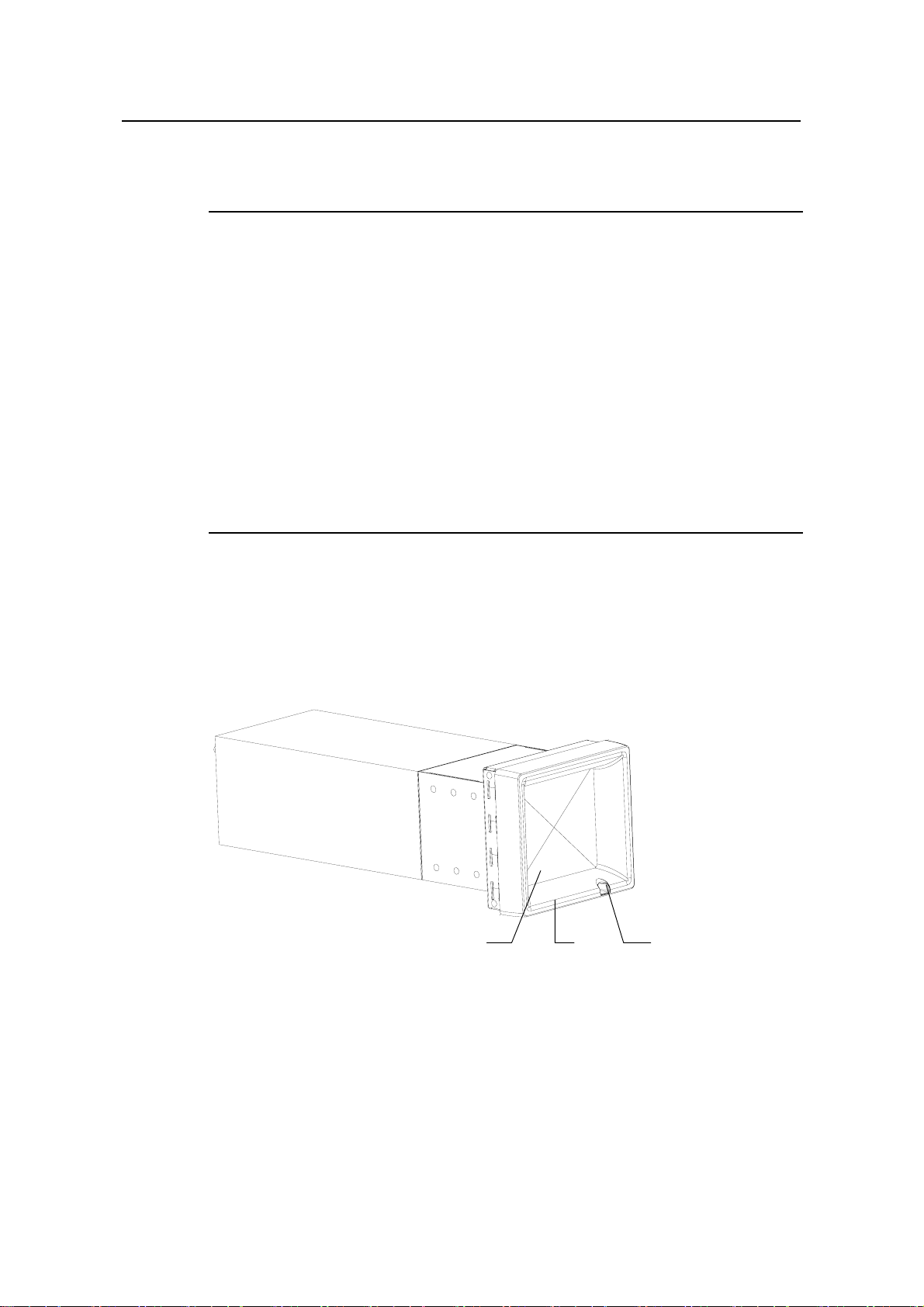
1.5.6 Fan Tray
The fan tray is located on the right side of the S7500 series. The fan tray is directly
connected to the backplane through a connector. All fan fault signals flow to the
backplane and then the backplane sends them to the SRPU for processing. The fan
tray is hot swappable.
Fan trays of the S7506R, S7503, and S7506 are slightly different. Fan trays of the
S7506R and S7503 are fixed by screws, while the fan tray of the S7506 is fixed by two
locks.
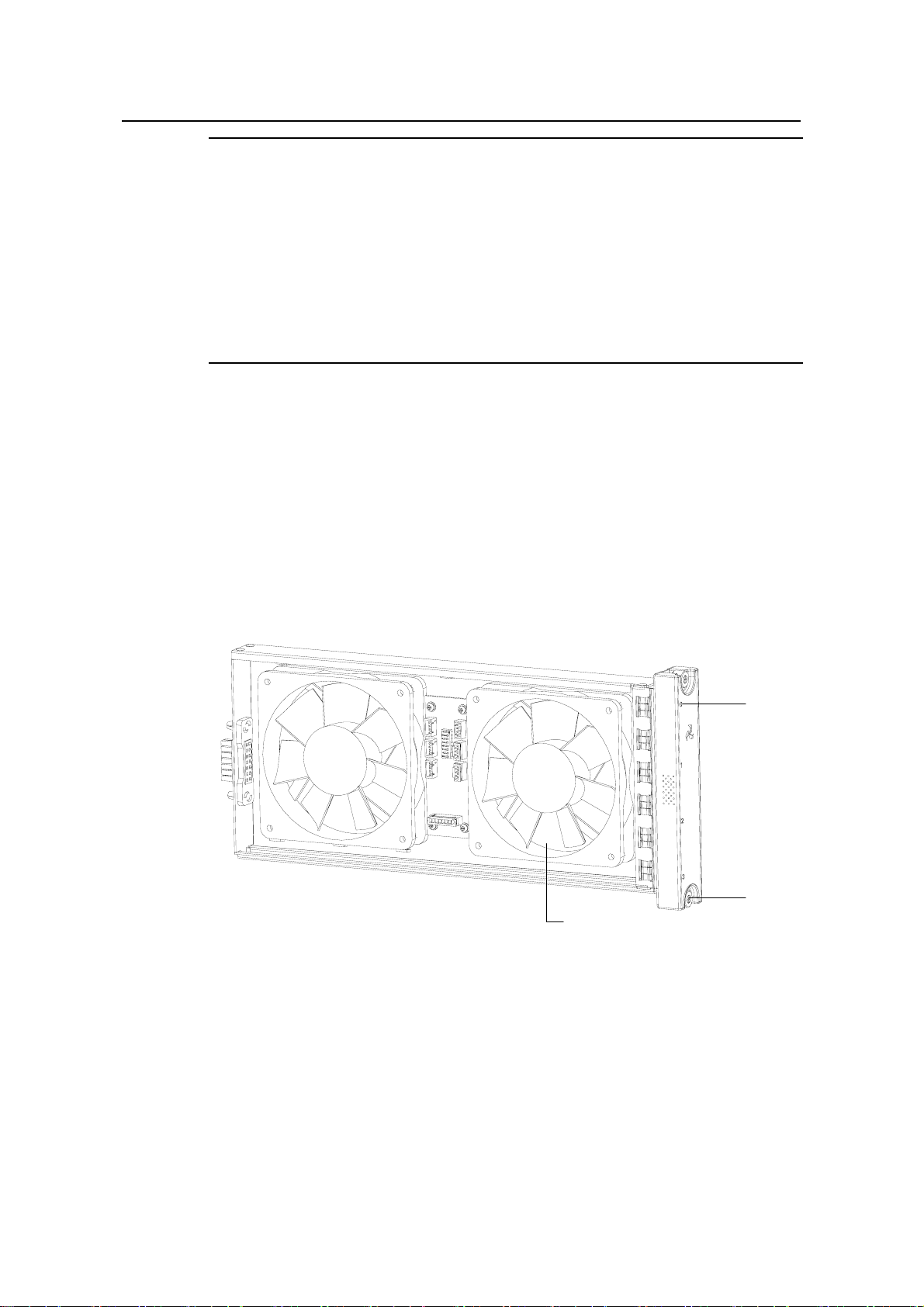
(1)
(3)
(1) LPU slot number (0 to 3) (2) Captive screw
(3) Fan
(2)
Figure 1-16 Fan tray of the S7503
1-23
Page 30
Installation Manual
H3C S7500 Series Ethernet Switches Chapter 1 Product Overview
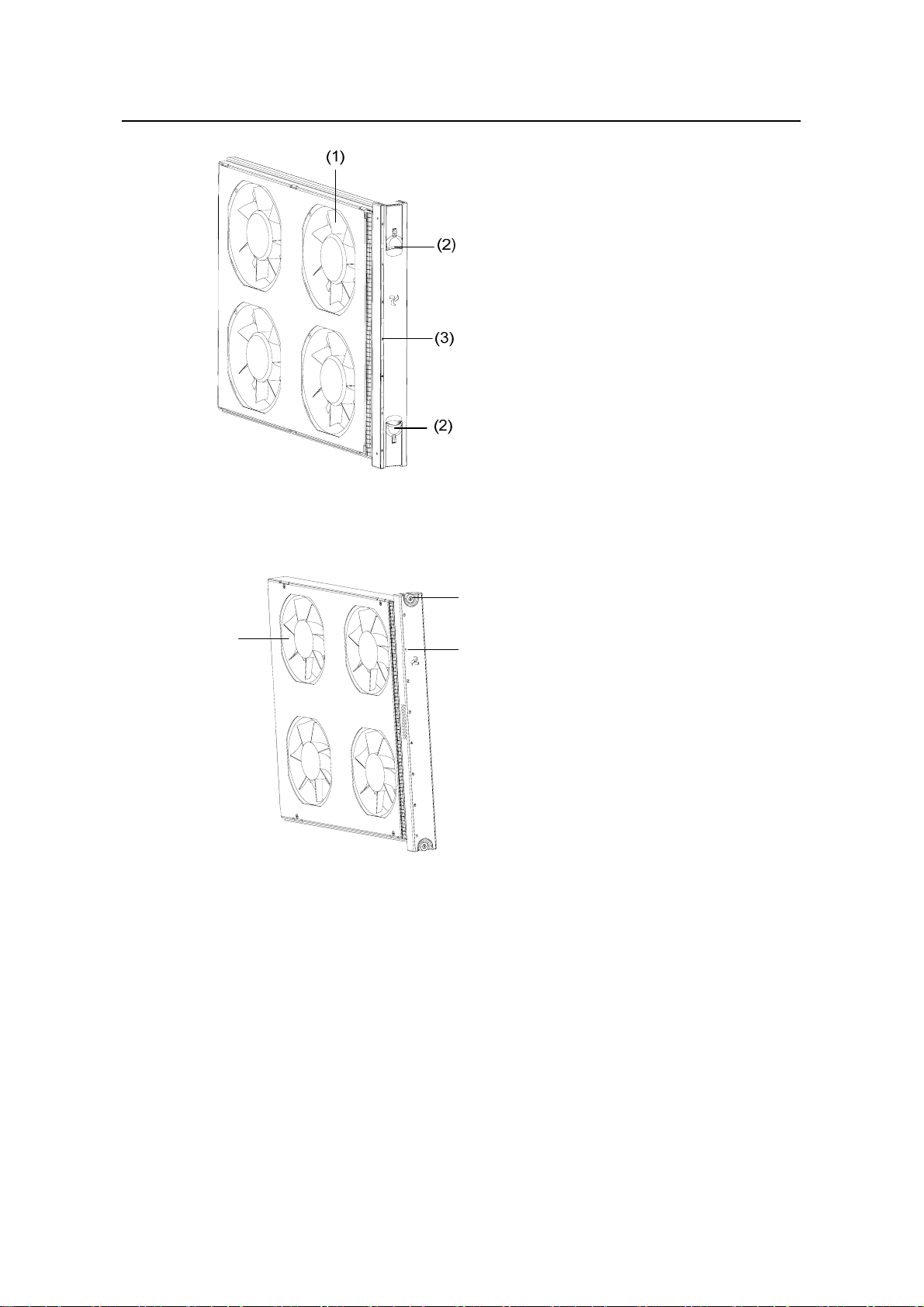
(1) Fan (2) Lock
(3) LPU slot number (0 to 6)
Figure 1-17 Fan tray of the S7506
(1)
(3)
(2)
(1) Captive screw (2) LPU slot number (0 to 7)
(3) Fan
Figure 1-18 Fan tray of the S7506R
The fan trays of the S7503 and S7506R are different from that of the S7506 in design.
z The fan trays of the S7503 and S7506R are fixed by screws.
z The fan tray of the S7506 is fixed by two locks.
Follow these steps to remove the fan tray from the S7503 chassis or S7506R chassi s:
1) Remove the screws from the fan tray.
2) Grasp the edge of the fan tray and gently pull it out.
Follow these steps to remove the fan tray from the S7506 chassis:
1-24
Page 31
Installation Manual
H3C S7500 Series Ethernet Switches Chapter 1 Product Overview
1) Simutaneously pull the two locks outward to release them.
2) Gently pull the fan tray out.
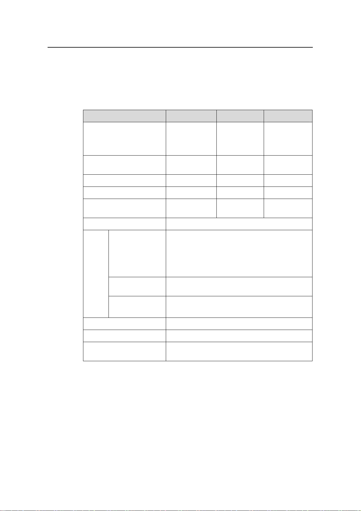
1.6 Technical Specifications for the S7500 Series
Table 1-16 Technical specifications for the S7500 series
Item S7503 S7506 S7506R
Physical dimensions (H × W
× D)
Weight (fully configured)
Number of SRPU slots 1 1 2
Number of LPU slots 3 6 6
Mean time between failures
(MTBF)
Mean time to repair (MTTR) 1 h
Power
distrib
ution
box
Dual-input
dual-switch AC
power distribution
box
S7503 AC power
distribution box
DC power
distribution box
352.8 × 436 ×
480 mm (13.9 x
17.2 x 18.9 in.)
≤ 50 kg (110.2
lb.)
185,000 h
110-120/220-240 VAC; 50 Hz or 60 Hz; 9.0/5.0 A
100 VAC to 240 VAC, 50 Hz or 60 Hz
Rated voltage: –48 VDC to –60 VDC
Maximum tolerance: –36 VDC to –72 VDC
486.2 × 436 ×
480 mm (19.1
x 17.2 x 18.9
in.)
≤ 70 kg (154.3
lb.)
160,000 h 221,000 h
530.6 × 436 ×
480 mm (20.9 x
17.2 x 18.9 in.)
≤ 80 kg (176.4
lb.)
PoE input voltage
Operating temperature
Operating humidity
(non-condensing)
–46 DCV to –55 DCV; 55.0 A
0ºC to 45ºC (32ºF to 113ºF)
10% to 90%
1-25
Page 32

Installation Manual
H3C S7500 Series Ethernet Switches Chapter 1 Product Overview
1.7 Compatibility Matrix Between Software Feature, SRPU and LPU
Table 1-17 Compatibility matrix between software feature, SRPU, and LPU
Feature SRPU LPU
MSTP Salience III Series
LACP Salience III Series No limitation
IPX Salience III Series No limitation
Protocol-based
VLAN
Salience III Series
All LPUs listed in
this manual
All LPUs listed in
this manual
Host software
version
Release
3000/3100 series
Release
3000/3100 series
Release
3000/3100 series
Release
3000/3100 series
1-26
Page 33

Installation Manual
H3C S7500 Series Ethernet Switches Table of Contents
Table of Contents
Chapter 2 Line Processing Units.................................................................................................2-1
2.1 Introduction to LPUs .......................................................................................................... 2-1
2.2 LS81FT48E........................................................................................................................2-1
2.2.1 Technical Specifications.......................................................................................... 2-1
2.2.2 Panel and LEDs ...................................................................................................... 2-2
2.2.3 Matching Cable ....................................................................................................... 2-3
2.3 LS81FT48F........................................................................................................................2-3
2.3.1 Technical Specifications.......................................................................................... 2-3
2.3.2 Panel and LEDs ...................................................................................................... 2-4
2.3.3 Matching Cable ....................................................................................................... 2-5
2.4 LS81FP48..........................................................................................................................2-5
2.4.1 Technical Specifications.......................................................................................... 2-6
2.4.2 Panel and LEDs ...................................................................................................... 2-6
2.4.3 Matching Cable ....................................................................................................... 2-7
2.5 LS81GT8UE.......................................................................................................................2-8
2.5.1 Technical Specifications.......................................................................................... 2-8
2.5.2 Panel and LEDs ...................................................................................................... 2-9
2.5.3 Matching Cable ..................................................................................................... 2-10
2.6 LS82GT20........................................................................................................................2-11
2.6.1 Technical Specifications........................................................................................ 2-11
2.6.2 Panel and LEDs .................................................................................................... 2-12
2.6.3 Matching Cable ..................................................................................................... 2-12
2.7 LS82GT20A.....................................................................................................................2-13
2.7.1 Technical Specifications........................................................................................ 2-13
2.7.2 Panel and LEDs .................................................................................................... 2-14
2.7.3 Matching Cable ..................................................................................................... 2-14
2.8 LS81GT48........................................................................................................................2-15
2.8.1 Technical Specifications........................................................................................ 2-15
2.8.2 Panel and LEDs .................................................................................................... 2-16
2.8.3 Matching Cable ..................................................................................................... 2-16
2.9 LS81GT48A.....................................................................................................................2-17
2.9.1 Technical Specifications........................................................................................ 2-17
2.9.2 Panel and LEDs .................................................................................................... 2-18
2.9.3 Matching Cable ..................................................................................................... 2-19
2.10 LS81GT48B................................................................................................................... 2-19
2.10.1 Technical Specifications...................................................................................... 2-19
2.10.2 Panel and LEDs..................................................................................................2-20
2.10.3 Matching Cable...................................................................................................2-21
i
Page 34

Installation Manual
H3C S7500 Series Ethernet Switches Table of Contents
2.11 LS81T12P......................................................................................................................2-21
2.11.1 Technical Specifications...................................................................................... 2-21
2.11.2 Panel and LEDs..................................................................................................2-22
2.11.3 Matching Cable...................................................................................................2-23
2.12 LS81T12PE....................................................................................................................2-25
2.12.1 Technical Specifications...................................................................................... 2-25
2.12.2 Panel and LEDs..................................................................................................2-26
2.12.3 Matching Cable...................................................................................................2-27
2.13 LS81P12T......................................................................................................................2-27
2.13.1 Technical Specifications...................................................................................... 2-27
2.13.2 Panel and LEDs..................................................................................................2-28
2.13.3 Matching Cable...................................................................................................2-29
2.14 LS81P12TE....................................................................................................................2-29
2.14.1 Technical Specifications...................................................................................... 2-29
2.14.2 Panel and LEDs..................................................................................................2-30
2.14.3 Matching Cable...................................................................................................2-31
2.15 LS81T16P......................................................................................................................2-31
2.15.1 Technical Specifications...................................................................................... 2-31
2.15.2 Panel and LEDs..................................................................................................2-32
2.15.3 Matching Cable...................................................................................................2-33
2.16 LS81T32P......................................................................................................................2-33
2.16.1 Technical Specifications...................................................................................... 2-33
2.16.2 Panel and LEDs..................................................................................................2-35
2.16.3 Matching Cable...................................................................................................2-36
2.17 LS81GP8UB ..................................................................................................................2-36
2.17.1 Technical Specifications...................................................................................... 2-36
2.17.2 Panel and LEDs..................................................................................................2-37
2.17.3 Matching Cable...................................................................................................2-38
2.18 LS82GP20 ..................................................................................................................... 2-38
2.18.1 Technical Specifications...................................................................................... 2-38
2.18.2 Panel and LEDs..................................................................................................2-39
2.18.3 Matching Cable...................................................................................................2-40
2.19 LS82GP20A...................................................................................................................2-40
2.19.1 Technical Specifications...................................................................................... 2-40
2.19.2 Panel and LEDs..................................................................................................2-41
2.19.3 Matching Cable...................................................................................................2-42
2.20 LS81GP48 ..................................................................................................................... 2-42
2.20.1 Technical Specifications...................................................................................... 2-43
2.20.2 Panel and LEDs..................................................................................................2-44
2.20.3 Matching Cable...................................................................................................2-44
2.21 LS81TGX1C...................................................................................................................2-45
2.21.1 Technical Specifications...................................................................................... 2-45
ii
Page 35

Installation Manual
H3C S7500 Series Ethernet Switches Table of Contents
2.21.2 Panel and LEDs..................................................................................................2-46
2.21.3 Matching Cable...................................................................................................2-47
2.22 LS81TGX2.....................................................................................................................2-47
2.22.1 Technical Specifications...................................................................................... 2-47
2.22.2 Panel and LEDs..................................................................................................2-48
2.22.3 Matching Cable...................................................................................................2-49
2.23 LS81TGX4.....................................................................................................................2-50
2.23.1 Technical Specifications...................................................................................... 2-50
2.23.2 Panel and LEDs..................................................................................................2-51
2.23.3 Matching Cable...................................................................................................2-52
2.24 LS81VSNP (without Port)..............................................................................................2-52
2.24.1 Technical Specifications...................................................................................... 2-52
2.24.2 Panel and LEDs..................................................................................................2-53
iii
Page 36

Installation Manual
H3C S7500 Series Ethernet Switches Chapter 2 Line Processing Units
Chapter 2 Line Processing Units
2.1 Introduction to LPUs
The modular design of the S700 series provides a reasonable system architecture as
well as standard, mutually independent function modules. Currently, the S7500 series
provide autosensing 10/100/1000 Mbps Ethernet electrical ports, 100 Mbps Ethernet
(single mode/multi-mode) optical ports, GBIC/SFP (single mode/multi-mode) optical
ports, and 10GE optical ports.
The following sections introduce the specifications and performance of LPUs in det ail.
2.2 LS81FT48E
Figure 2-1 LS81FT48E appearance
2.2.1 Technical Specifications
The LS81FT48E provides forty-eight autosensing 10/100Base-TX Ethernet port s.
Table 2-1 LS81FT48E specifications
Item Specification
CPU MPC8241, 200 MHz
Boot ROM 512 KB
SDRAM 128 MB
Dimensions (H x W x D)
Maximum power consumption 35 W
Connector RJ-45
Number of ports 48
40.1 × 376.7 × 354.5 mm (1.6 × 14.8 ×
14 in.)
Port speed
z 10/100 Mbps half-duplex/full-duplex
z MDI/MDI-X autosensing
2-1
Page 37

Installation Manual
H3C S7500 Series Ethernet Switches Chapter 2 Line Processing Units
Item Specification
Matching cable and maximum
transmission distance
Compliant standards
2.2.2 Panel and LEDs
Category-5 twisted pair with a maximum
transmission distance of 100 m (328.1 ft)
IEEE 802.3
IEEE 802.3u
IEEE 802.3ad
IEEE 802.3x
IEEE 802.1p
IEEE 802.1D
IEEE 802.1Q
IEEE 802.1X
IEEE 802.1s
IEEE 802.1w
Figure 2-2 LS81FT48E panel
(1) Silkscreen of the LPU name (2) Captive screw
(3) LPU edge (purple) (4) Ejector lever
(5) 10/100Base-TX Ethernet port status LED (6) 10/100Base-TX Ethernet port
Figure 2-3 Partially amplified view of the LS81FT48E panel
Each 10/100Base-TX Ethernet port has a green LED.
2-2
Page 38

Installation Manual
H3C S7500 Series Ethernet Switches Chapter 2 Line Processing Units
Table 2-2 LED description of the LS81FT48E
LED Status Meaning
LINK/ACT
2.2.3 Matching Cable
The 10/100Base-TX Ethernet ports use category-5 twisted pairs a nd RJ-45 connectors,
with a maximum transmission distance of 100 m (328.1 ft ).
2.3 LS81FT48F
OFF
ON
Blinking
No link is present.
A link is present.
Data is being transmitted/received.
Figure 2-4 LS81FT48F appearance
2.3.1 Technical Specifications
The LS81FT48F provides forty-eight autosensing 10/100Base-TX Ethernet ports. All
the ports support PoE, that is, they can supply power to remote PDs through Ethernet
twisted pairs.
Table 2-3 LS81FT48F specifications
Item Specification
CPU MPC8241, 200 MHz
Boot ROM 512 KB
SDRAM 128 MB
Dimensions (H x W x D)
Maximum power consumption 35 W
Connector RJ-45
Number of ports 48
40.1 × 376.7 × 354.5 mm (1.6 × 14.8 ×
14 in.)
2-3
Page 39

Installation Manual
H3C S7500 Series Ethernet Switches Chapter 2 Line Processing Units
Item Specification
Port speed
Matching cable and maximum
transmission distance
z 10/100 Mbps half-duplex/full-duplex
z MDI/MDI-X autosensing
Category-5 twisted pair, with a maximum
transmission distance of 100 m (328.1 ft)
Maximum PoE distance 100 m (328.1 ft)
Maximum power each port can provide 15.4 W
IEEE 802.3
IEEE 802.3u
IEEE 802.3x
IEEE 802.3ad
IEEE 802.1p
Compliant standard
IEEE 802.1D
IEEE 802.1Q
IEEE 802.1X
IEEE 802.1s
IEEE 802.1w
IEEE 802.3af
2.3.2 Panel and LEDs
Figure 2-5 LS81FT48F panel
2-4
Page 40

Installation Manual
H3C S7500 Series Ethernet Switches Chapter 2 Line Processing Units
(1) Silkscreen of the LPU name (2) Captive screw
(3) LPU edge (purple) (4) Ejector lever
(5) 10/100Base-TX Ethernet port status LED
(6) 10/100Base-TX Ethernet port (supporting
PoE)
Figure 2-6 Partially amplified view of the LS81FT48F panel
Each 10/100Base-TX Ethernet port has a green LED.
Table 2-4 LED description of the LS81FT48F
LED Status Meaning
LINK/ACT
2.3.3 Matching Cable
The 10/100Base-TX Ethernet ports use category-5 twisted pairs a nd RJ-45 connectors,
with a maximum transmission distance of 100 m (328.1 ft ).
2.4 LS81FP48
OFF
ON
Blinking
No link is present.
A link is present.
Data is being transmitted/received.
Figure 2-7 LS81FP48 appearance
2-5
Page 41

Installation Manual
H3C S7500 Series Ethernet Switches Chapter 2 Line Processing Units
2.4.1 Technical Specifications
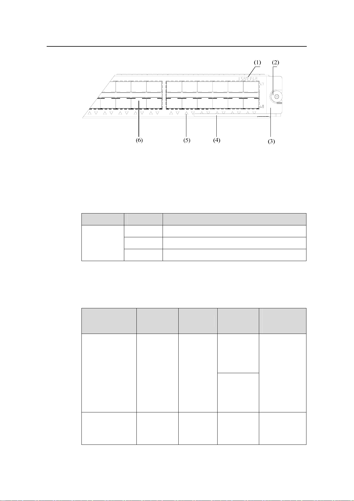
The LS81FP48 provides forty-eight 100Base-FX-SFP port s opera ting in the full-duplex
mode.
Table 2-5 LS81FP48 specifications
Item Specification
CPU MPC8241, 200 MHz
Boot ROM 512 KB
SDRAM 128 MB
Dimensions (H x W x D)
40.1 × 376.7 × 354.5 mm (1.6 × 14.8 ×
14 in.)
Maximum power consumption 60 W
Connector LC
Number of ports 48
Port speed 100 Mbps full-duplex
z SFP-FE-SX-MM1310-A
z SFP-FE-LX-SM1310-A
SFP module
Compliant standard
z SFP-FE-LH40-SM1310
z SFP-FE-LH80-SM1550
z SFP-FE-LX-SM1310-BIDI
z SFP-FE-LX-SM1550-BIDI
z IEEE 802.3
z IEEE 802.1p
z IEEE 802.1Q
z IEEE 802.1D
z IEEE 802.3x
z IEEE 802.3ad
z IEEE 802.1X
z IEEE 802.1s
z IEEE 802.1w
2.4.2 Panel and LEDs
Figure 2-8 LS81FP48 panel
2-6
Page 42
Installation Manual
H3C S7500 Series Ethernet Switches Chapter 2 Line Processing Units
(1) Silkscreen of the LPU name (2) Captive screw
(3) LPU edge (purple) (4) Ejector lever
(5) 100Base-FX-SFP port status LED (6) 100Base-FX-SFP port
Figure 2-9 Partially amplified view of the LS81FP48 panel
Each 100Base-FX-SFP port has a green LED.
Table 2-6 LED description of the LS81FP48
LED Status Meaning
LINK/ACT
2.4.3 Matching Cable
Table 2-7 Cables for 100Base-FX-SFP ports of the LS81FP48
SFP module
SFP-FE-SX-MM1
310-A
OFF
ON
Blinking
Central
wavelength
1,310 nm LC
No link is present.
A link is present.
Data is being transmitted/received.
Connector
Matching
cable
50 µm/125
µm
multimode
optical fiber
cable
62.5 µm/125
µm
multimode
optical fiber
cable
Maximum
transmission
distance
2 km (1.2 mi)
SFP-FE-LX-SM13
10-A
1,310 nm LC
2-7
9 µm/125 µm
single mode
optical fiber
cable
15 km (9.3 mi)
Page 43
Installation Manual
H3C S7500 Series Ethernet Switches Chapter 2 Line Processing Units
Maximum
transmission
distance
40 km (24.9 mi)
80 km (49.7 mi)
SFP module
SFP-FE-LH40-SM
1310
SFP-FE-LH80-SM
1550
Central
wavelength
1,310 nm LC
1,550 nm LC
Connector
Matching
cable
9 µm/125 µm
single mode
optical fiber
cable
9 µm/125 µm
single mode
optical fiber
cable
SFP-FE-LX-SM13
10-BIDI
SFP-FE-LX-SM15
50-BIDI
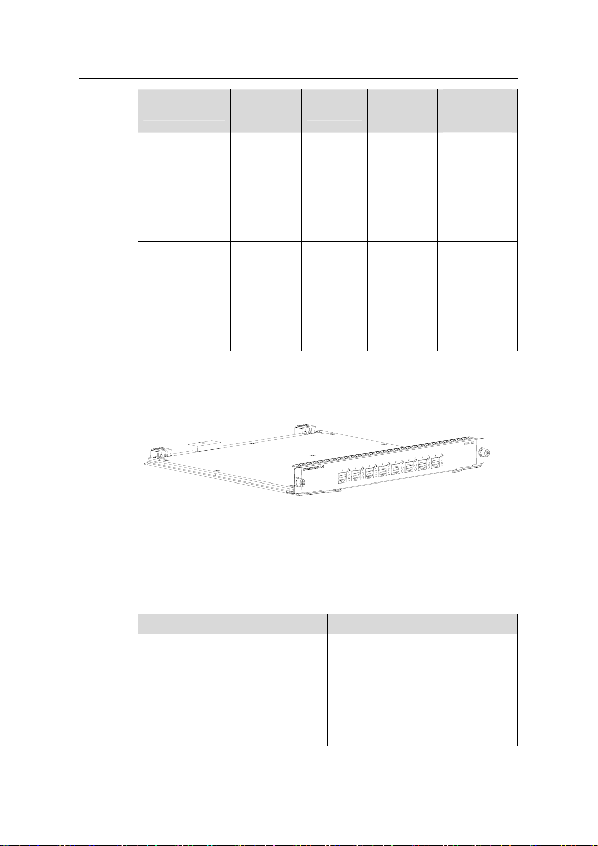
2.5 LS81GT8UE
Figure 2-10 LS81GT8UE appearance
1,550 nm
(receive)/131
0 nm
(transmit)
1310
(transmit)/15
50 (receive)
LC
LC
9µm/125µm
single mode
optical fiber
cable
9µm/125µm
single mode
optical fiber
cable
15 km (9.3 mi)
15 km (9.3 mi)
2.5.1 Technical Specifications
The LS81GT8UE provides eight autosensing 10/100/1000Base-T Ethernet po rts.
Table 2-8 LS81GT8UE specifications
Item Specification
CPU MPC850, 50 MHz
Boot ROM 512 KB
SDRAM 64 MB
Dimensions (H x W x D)
Maximum power consumption 11 W
40.1 × 376.7 × 354.5 mm (1.6 × 14.8 ×
14 in.)
2-8
Page 44

Installation Manual
H3C S7500 Series Ethernet Switches Chapter 2 Line Processing Units
Item Specification
Connector RJ-45
Number of ports 8
z 10/100/1000 Mbps
Port speed
half-duplex/full-duplex
z MDI/MDI-X autosensing
Matching cable and maximum
transmission distance
Compliant standard
Category-5 twisted pair, with a maximum
transmission distance of 100 m (328.1 ft)
z IEEE 802.3
z IEEE 802.3u
z IEEE 802.3ab
z IEEE 802.3x
z IEEE 802.1D
z IEEE 802.1Q
z IEEE 802.1X
z IEEE 802.1s
z IEEE 802.1w
Note:
z The LS81GT8UE can only be used together with Salience III or Salience III Edge
SRPUs.
z If a Salience III or Salience III Edge SRPU is used, the LS81GT8UE cannot be
inserted in the last LPU slot of the S7506 or the S7506R (slot 6 for the S7506 and
slot 7 for the S7506R), but can be inserted in any LPU slot of the S7503.
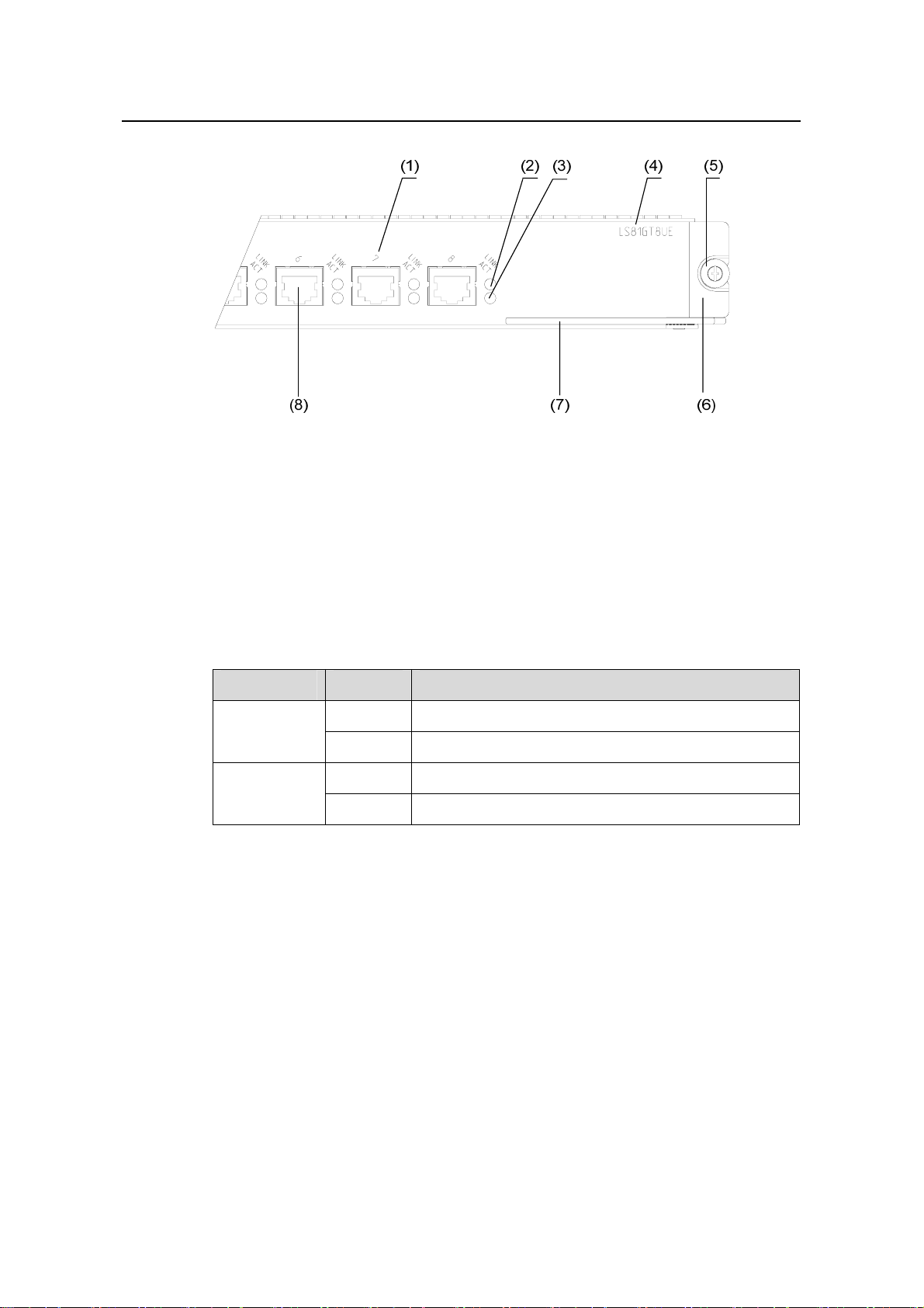
2.5.2 Panel and LEDs
Figure 2-11 LS81GT8UE panel
2-9
Page 45
Installation Manual
H3C S7500 Series Ethernet Switches Chapter 2 Line Processing Units
(1) Ethernet port number
(3) 10/100/1000Base-T Ethernet port status
LED (ACT)
(5) Captive screw (6) LPU edge (purple)
(7) Ejector lever
Figure 2-12 Partially amplified view of the LS81GT8UE panel
Each 10/100/1000Base-T Ethernet port has two LEDs.
Table 2-9 LED description of the LS81GT8UE
LED Status Meaning
LINK
ACT
2.5.3 Matching Cable
(2) 10/100/1000Base-T Ethernet port status
LED (LINK)
(4) Silkscreen of the LPU name
(8) 10/100/1000Base-T Ethernet port
(Gigabit)
OFF No link is present.
ON A link is present.
OFF No data is being transmitted/received.
Blinking Data is being transmitted/received.
The ports use category-5 twisted pairs and RJ-45 connectors, with a maximum
transmission distance of 100 m (328.1 ft).
2-10
Page 46
Installation Manual
H3C S7500 Series Ethernet Switches Chapter 2 Line Processing Units
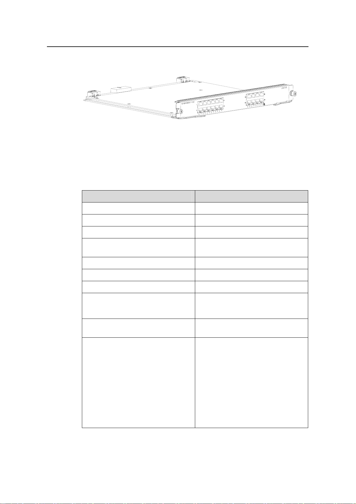
2.6 LS82GT20
Figure 2-13 LS82GT20 appearance
2.6.1 Technical Specifications
The LS82GT20 provides twenty autosensing 10/100/1000Base-T Ethernet ports.
Table 2-10 LS82GT20 specifications
Item Specification
CPU MPC8241, 200 MHz
Boot ROM 512 KB
SDRAM 64 MB
Dimensions (H x W x D)
40.1 × 376.7 × 354.5 mm (1.6 × 14.8 ×
14 in.)
Maximum power consumption 45 W
Connector RJ-45
Number of ports 20
z 10/100 Mbps half-duplex/full-duplex
Port speed
Matching cable and maximum
transmission distance
Compliant standard
z 1000 Mbps full-duplex
z MDI/MDI-X autosensing
Category-5 twisted pair, with a maximum
transmission distance of 100 m (328.1 ft)
z IEEE 802.3
z IEEE 802.3u
z IEEE 802.3ab
z IEEE 802.3x
z IEEE 802.1p
z IEEE 802.1D
z IEEE 802.1Q
z IEEE 802.1X
z IEEE 802.1w
z IEEE 802.1ad
z IEEE 802.1s
2-11
Page 47
Installation Manual
H3C S7500 Series Ethernet Switches Chapter 2 Line Processing Units
2.6.2 Panel and LEDs
Figure 2-14 LS82GT20 panel
(1) Silkscreen of the LPU name (2) Captive screw
(3) LPU edge (purple) (4) Ejector lever
(5) 10/100/1000Base-T Ethernet port
Figure 2-15 Partially amplified view of the LS82GT20 panel
Each 10/100/1000Base-T Ethernet port has a LED.
Table 2-11 LED description of the LS82GT20
LED Status Meaning
LINK/ACT
2.6.3 Matching Cable
The ports use category-5 twisted pairs and RJ-45 connectors, with a maximum
transmission distance of 100 m (328.1 ft).
OFF
ON
Blinking
(6) 10/100/1000Base-T Ethernet port status
LED
No link is present.
A link is present.
Data is being transmitted/received.
2-12
Page 48

Installation Manual
H3C S7500 Series Ethernet Switches Chapter 2 Line Processing Units
2.7 LS82GT20A
Figure 2-16 LS82GT20A appearance
2.7.1 Technical Specifications
The LS82GT20A provides twenty autosensing 10/100/1000Base-T Ethernet ports.
Table 2-12 LS82GT20A specifications
Item Specification
CPU MPC8241, 200 MHz
Boot ROM 512 KB
SDRAM 128 MB
Dimensions (W x D)
40.1 × 376.7 × 354.5 mm (1.6 × 14.8 ×
14 in.)
Maximum power consumption 45 W
Connector RJ-45
Number of ports 20
z 10/100 Mbps half-duplex/full-duplex
Port speed
Matching cable and maximum
transmission distance
Compliant standard
z 1000 Mbps full-duplex
z MDI/MDI-X autosensing
Category-5 twisted pair, with a maximum
transmission distance of 100 m (328.1 ft)
z IEEE 802.3
z IEEE 802.3u
z IEEE 802.3ab
z IEEE 802.3x
z IEEE 802.1p
z IEEE 802.1D
z IEEE 802.1Q
z IEEE 802.1X
z IEEE 802.1w
z IEEE 802.1ad
z IEEE 802.1s
2-13
Page 49

Installation Manual
H3C S7500 Series Ethernet Switches Chapter 2 Line Processing Units
2.7.2 Panel and LEDs
Figure 2-17 LS82GT20A panel
(1) 10/100/1000Base-T Ethernet port (2) Silkscreen of the LPU name
(3) Captive screw (4) LPU edge (purple)
(5) Ejector lever (6) Ethernet port status LED
Figure 2-18 Partially amplified view of the LS82GT20A panel
Each 10/100/1000Base-T Ethernet port has a LED.
Table 2-13 LED description of the LS82GT20A
LED Status Meaning
LINK/ACT
2.7.3 Matching Cable
The ports use category-5 twisted pairs and RJ-45 connectors, with a maximum
transmission distance of 100 m (328.1 ft).
OFF
ON
Blinking
No link is present.
A link is present.
Data is being transmitted/received.
2-14
Page 50

Installation Manual
H3C S7500 Series Ethernet Switches Chapter 2 Line Processing Units
2.8 LS81GT48
Figure 2-19 LS81GT48 appearance
2.8.1 Technical Specifications
The LS81GT48 provides forty-eight autosensing 10/100/1000Base-T Ethernet ports.
Table 2-14 LS81GT48 specifications
Item Specification
CPU MPC8241, 200 MHz
Boot ROM 512 KB
SDRAM 128 MB
Dimensions (H x W x D)
40.1 × 376.7 × 354.5 mm (1.6 × 14.8 ×
14 in.)
Maximum power consumption 70 W
Connector RJ-45
Number of ports 48
z 10/100/1000 Mbps
Port speed
Matching cable and maximum
transmission distance
Compliant standard
half-duplex/full-duplex
z MDI/MDI-X autosensing
Category-5 twisted pair, with a maximum
transmission distance of 100 m (328.1 ft)
z IEEE 802.3
z IEEE 802.3u
z IEEE 802.3ab
z IEEE 802.3x
z IEEE 802.1p
z IEEE 802.1D
z IEEE 802.1Q
z IEEE 802.1X
z IEEE 802.1s
z IEEE 802.1w
2-15
Page 51

Installation Manual
H3C S7500 Series Ethernet Switches Chapter 2 Line Processing Units
2.8.2 Panel and LEDs
Figure 2-20 LS81GT48 panel
(1) Silkscreen of the LPU name (2) Captive screw
(3) LPU edge (purple) (4) Ejector lever
(5) 10/100/1000Base-T Ethernet port status LED (6) 10/100/10 0 0Base-T Ethernet port
Figure 2-21 Partially amplified view of the LS81GT48 panel
Each 10/100/1000Base-T Ethernet port has a green LED.
Table 2-15 LED description of the LS81GT48
LED Status Meaning
LINK/ACT
2.8.3 Matching Cable
The ports use category-5 twisted pairs and RJ-45 connectors, with a maximum
transmission distance of 100 m (328.1 ft).
OFF
ON
Blinking
No link is present.
A link is present.
Data is being transmitted/received.
2-16
Page 52

Installation Manual
H3C S7500 Series Ethernet Switches Chapter 2 Line Processing Units
2.9 LS81GT48A
Figure 2-22 LS81GT48A appearance
2.9.1 Technical Specifications
The LS81GT48A provides forty-eight autosensing 10/100/1000Base-T Ethernet ports.
All the ports support PoE, that is, they supply power to remote PDs through Ethernet
twisted pair cables.
Table 2-16 LS81GT48A specifications
Item Specification
CPU MPC8241, 200 MHz
Boot ROM 512 KB
SDRAM 128 MB
Dimensions (H x W x D)
40.1 × 376.7 × 354.5 mm (1.6 × 14.8 ×
14 in.)
Maximum power consumption 70 W
Connector RJ-45
Number of ports 48
z 10/100/1000 Mbps
Port speed
Matching cable and maximum
transmission distance
half-duplex/full-duplex
z MDI/MDI-X autosensing
Category-5 twisted pair, with a maximum
transmission distance of 100 m (328.1 ft)
Maximum PoE distance 100 m (328.1 ft)
Maximum power each port can provide 15.4 W
2-17
Page 53

Installation Manual
H3C S7500 Series Ethernet Switches Chapter 2 Line Processing Units
Item Specification
z IEEE 802.3
z IEEE 802.3u
z IEEE 802.3ab
z IEEE 802.3x
z IEEE 802.1p
Compliant standard
z IEEE 802.1D
z IEEE 802.1Q
z IEEE 802.1X
z IEEE 802.1s
z IEEE 802.1w
z IEEE 802.3af
2.9.2 Panel and LEDs
Figure 2-23 LS81GT48A panel
(1) Silkscreen of the LPU name (2) Captive screw
(3) LPU edge (purple) (4) Ejector lever
(5) 10/100/1000Base-T Ethernet port status LED (6) 10/100/1000Base-T Ethernet port
Figure 2-24 Partially amplified view of the LS81GT48A panel
Each 10/100/1000Base-T Ethernet port has a green LED.
2-18
Page 54

Installation Manual
H3C S7500 Series Ethernet Switches Chapter 2 Line Processing Units
Table 2-17 LED description of the LS81GT48A
LED Status Meaning
LINK/ACT
2.9.3 Matching Cable
The 10/100/1000Base-T Ethernet ports use category-5 twisted pairs and RJ-45
connectors, with a maximum transmission distance of 100 m (328.1 ft).
2.10 LS81GT48B
Figure 2-25 LS81GT48B appearance
OFF
ON
Blinking
No link is present.
A link is present.
Data is being transmitted/received.
2.10.1 Technical Specifications
The LS81GT48B adopts an XG high-speed bus. It can also serve as the SRPU of the
S7502.
Table 2-18 LS81GT48B specifications
Item Specification
CPU MPC8245, 300 MHz
BOOT ROM 512 KB
Flash memory 32 MB
SDRAM 256 MB
Dimensions (H x W x D)
Maximum power consumption 107 W
Connector RJ-45
Number of ports 48
40.1 x 376.7 x 364.5 mm (1.6 × 14.8 × 14
in.)
2-19
Page 55

Installation Manual
H3C S7500 Series Ethernet Switches Chapter 2 Line Processing Units
Item Specification
z 10 Mbps half-duplex/full-duplex
Port speed
z 100 Mbps half-duplex/full-duplex
z 1000 Mbps half-duplex/full-duplex
z MDI/MDI-X autosensing
Matching cable and maximum
transmission distance
Compliant standard
Category-5 twisted pair, with a maximum
transmission distance of 100 m (328.1 ft)
z IEEE 802.3
z IEEE 802.3u
z IEEE 802.3ab
z IEEE 802.3x
z IEEE 802.1p
z IEEE 802.1D
z IEEE 802.1Q
z IEEE 802.1X
z IEEE 802.1s
z IEEE 802.1w
Note:
When using the LS81GT48B as an LPU of the S7503/S7506/S7506R, you can only
use it together with a Salience III or Salience III Plus SRPU:
z If you use the LS81GT48B together with a Salience III Plus SRPU, you can insert it
into any LPU slot on the S7503/S7506/S7506R.
z If you use the LS81GT48B together with a Salience III SRPU, you can only insert it
into one of the last two LPU slots on the S7503/S7506/S7506R switch (slot 2 or 3 for
the S7503, slot 5 or 6 for the S7506, and slot 6 or 7 for the S7506R).
2.10.2 Panel and LEDs
Figure 2-26 LS81GT48B panel
2-20
Page 56

Installation Manual
H3C S7500 Series Ethernet Switches Chapter 2 Line Processing Units
(1) Silkscreen of the LPU name (2) Captive screw
(3) LPU edge (purple) (4) Ejector lever
(5) 10/100/1000Base-T Ethernet port status LED (6) 10/100/10 0 0Base-T Ethernet port
Figure 2-27 Partially amplified view of the LS81GT48B panel
Each 10/100/1000Base-T Ethernet port has a green LED.
Table 2-19 LED description of the LS81GT48B
LED Status Meaning
LINK/ACT
2.10.3 Matching Cable
The 10/100/1000Base-T Ethernet ports use category-5 twisted pairs and RJ-45
connecters, with a maximum transmission distance of 100 m (328.1 ft).
2.11 LS81T12P
OFF
ON
Blinking
No link is present.
A link is present.
Data is being transmitted/received.
Figure 2-28 LS81T12P appearance
2.11.1 Technical Specifications
The LS81T12P provides twelve autosensing 10/100/1000Base-T Ethernet ports and
four 1000Base-X-SFP ports operatin g in the full-duplex mode.
2-21
Page 57
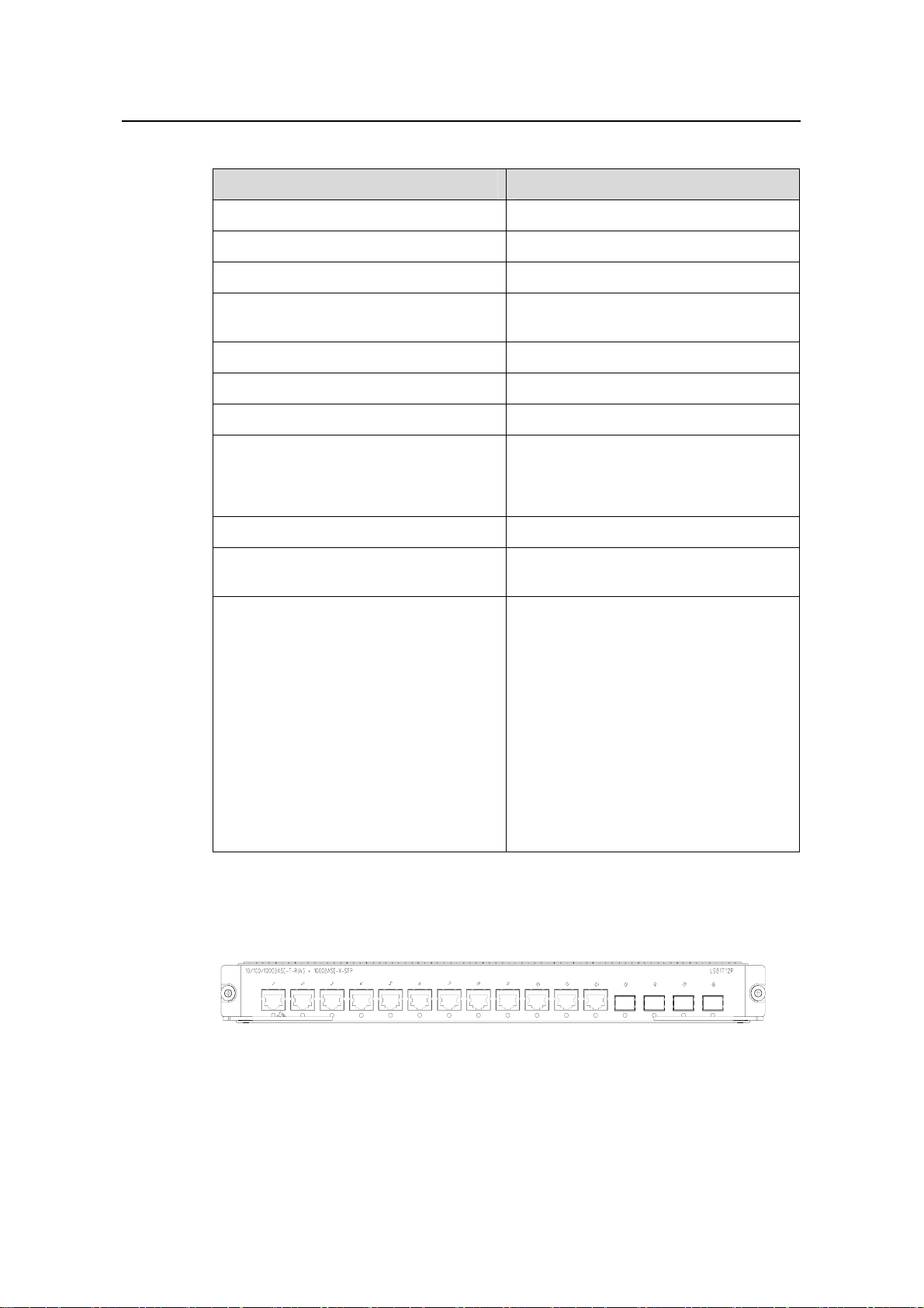
Installation Manual
H3C S7500 Series Ethernet Switches Chapter 2 Line Processing Units
Table 2-20 LS81T12P specifications
Item Specification
CPU MPC8241, 200 MHz
Boot ROM 512 KB
SDRAM 128 MB
Dimensions (H x W x D)
40.1 × 376.7 × 354.5 mm (1.6 × 14.8 ×
14 in.)
Maximum power consumption 33 W
Connector RJ-45, LC
Number of ports 16
z 1000 Mbps full-duplex
Port speed
(optical/electrical)
z 10/100 Mbps half-duplex/full-duplex
(electrical)
SFP modules Refer to Table 2-22
Matching cable and maximum
transmission distance
Compliant standard
Category-5 twisted pair, with a maximum
transmission distance of 100 m (328.1 ft)
z IEEE 802.3
z IEEE 802.3u
z IEEE 802.3z
z IEEE 802.3ab
z IEEE 802.1p
z IEEE 802.1Q
z IEEE 802.1D
z IEEE 802.1X
z IEEE 802.1s
z IEEE 802.1w
z IEEE 802.3x
z IEEE 802.3ad
2.11.2 Panel and LEDs
Figure 2-29 LS81T12P panel
2-22
Page 58
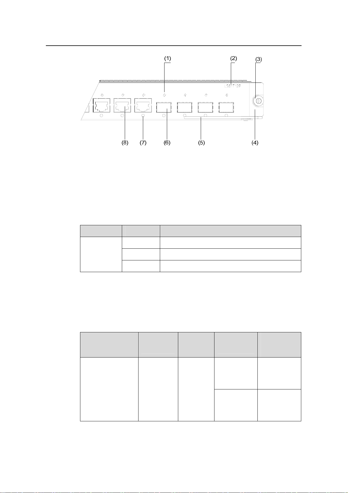
Installation Manual
H3C S7500 Series Ethernet Switches Chapter 2 Line Processing Units
(1) Port number (2) Silkscreen of the LPU name
(3) Captive screw (4) LPU edge (purple)
(5) Ejector lever (6) 1000Base-X-SPF port
(7) 10/100/1000Base-T Ethernet port status LED (8) 10/100/10 0 0Base-T Ethernet port
Figure 2-30 Partially amplified view of the LS81T12P panel
The following table describes the LED.
Table 2-21 LED description of the LS81T12P
LED Status Meaning
LINK/ACT
2.11.3 Matching Cable
I. Cables for the four 1000Base-X-SFP ports
Table 2-22 Cables for 1000Base-X-SFP ports
SFP module
SFP-GE-SX-MM85
0-A
OFF
ON
Blinking
Central
wavelength
850 nm LC
No link is present.
A link is present.
Data is being transmitted/received.
Connector
Matching
cable
50 µm/125 µm
multimode
optical fiber
cable
62.5 µm/125
µm multimode
optical fiber
cable
Maximum
transmission
distance
550 m (1804
ft)
275 m (902 ft)
2-23
Page 59

Installation Manual
H3C S7500 Series Ethernet Switches Chapter 2 Line Processing Units
Maximum
transmission
distance
SFP module
Central
wavelength
Connector
Matching
cable
SFP-GE-LX-SM131
0-A
SFP-GE-LH40-SM1
310
SFP-GE-LH40-SM1
550
SFP-GE-LH70-SM1
550
SFP-GE-LH100-SM
1550
SFP-GE-LH70-SM1
470-CW
SFP-GE-LH70-SM1
490-CW
SFP-GE-LH70-SM1
510-CW
1,310 nm LC
1,550 nm LC
1,470 nm LC
1,490 nm LC
1,510 nm LC
9 µm/125 µm
single mode
optical fiber
cable
9 µm/125 µm
single mode
optical fiber
cable
9 µm/125 µm
single mode
optical fiber
cable
9 µm/125 µm
single mode
optical fiber
cable
9 µm/125 µm
single mode
optical fiber
cable
10 km (6 mi)
40 km (25 mi)
40 km (about
25 mi)
70 km (43 mi)
100 km (62
mi)
70 km (43 mi)
70 km (43 mi)
70 km (43 mi)
SFP-GE-LH70-SM1
530-CW
SFP-GE-LH70-SM1
550-CW
SFP-GE-LH70-SM1
570-CW
SFP-GE-LH70-SM1
590-CW
SFP-GE-LH70-SM1
610-CW
1,530 nm LC
1,550 nm LC
1,570 nm LC
1,590 nm LC
1,610 nm LC
9 µm/125 µm
single mode
optical fiber
cable
9 µm/125 µm
single mode
optical fiber
cable
9 µm/125 µm
single mode
optical fiber
cable
9 µm/125 µm
single mode
optical fiber
cable
9 µm/125 µm
single mode
optical fiber
cable
70 km (43 mi)
70 km (43 mi)
70 km (43 mi)
70 km (43 mi)
70 km (43 mi)
2-24
Page 60
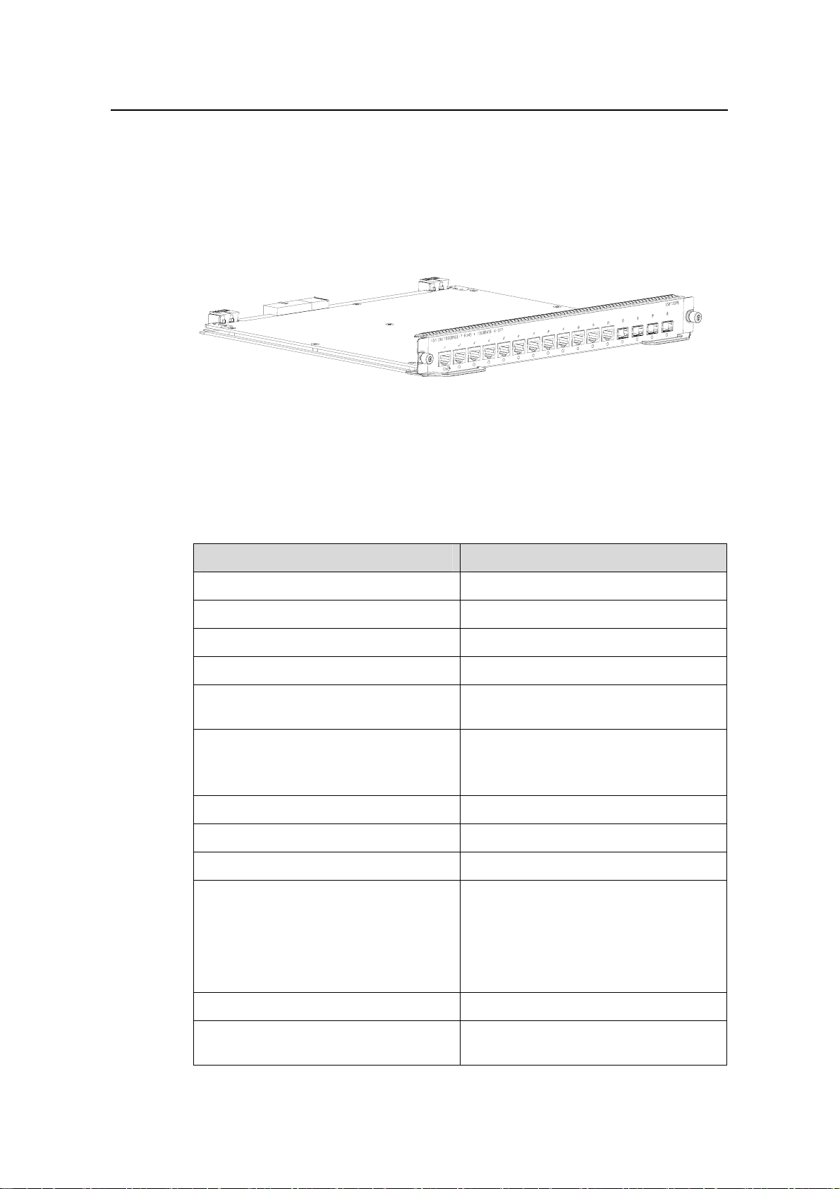
Installation Manual
H3C S7500 Series Ethernet Switches Chapter 2 Line Processing Units
II. Cables for the twelve 10/100/1000Base-T Ethernet ports
The 10/100/1000Base-T Ethernet ports use category-5 twisted pairs and RJ-45
connectors, with a maximum transmission distance of 100 m (328.1 ft).
2.12 LS81T12PE
Figure 2-31 LS81T12PE appearance
2.12.1 Technical Specifications
The LS81T12PE can serve as the SRPU of the S7502.
Table 2-23 LS81T12PE specifications
Item Specification
CPU MPC8245, 300 MHz
Boot ROM 512 KB
Flash memory 32 MB
SDRAM 256 MB
Dimensions (H x W x D)
40.1 × 376.7 × 354.5 mm (1.6 × 14.8 ×
14 in.)
Twelve 10/100/1000Base-T Ethernet
Number of ports
ports
Four 1000BASE-X-SFP ports
Maximum power consumption 29 W
Connector RJ-45, LC
Number of ports 16
z 1000 Mbps full-duplex (optical port)
z 10 Mbps half-duplex/full-duplex
Port speed
(electrical port)
z 100 Mbps half-duplex/full-duplex
(electrical port)
z 1000M full-duplex (electrical port)
SFP modules Refer to Table 2-22
Port cable and max transmission
distance
2-25
Category-5 twisted pair, with a maximum
transmission distance of 100 m (328.1 ft)
Page 61
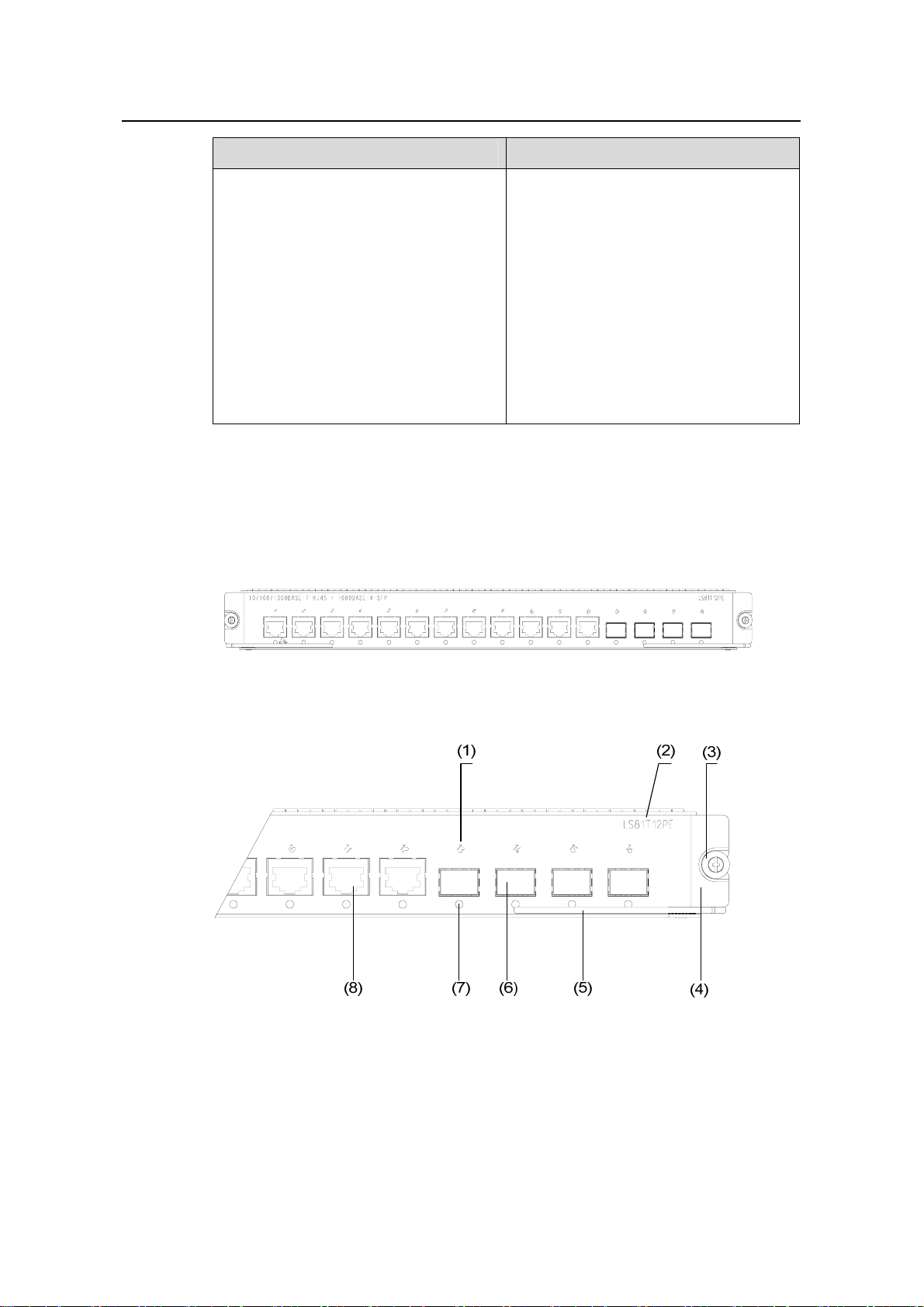
Installation Manual
H3C S7500 Series Ethernet Switches Chapter 2 Line Processing Units
Item Specification
z IEEE 802.3
z IEEE 802.3u
z IEEE 802.3z
z IEEE 802.3ab
z IEEE 802.1p
Compliant standard
z IEEE 802.1Q
z IEEE 802.1D
z IEEE 802.1X
z IEEE 802.1s
z IEEE 802.1w
z IEEE 802.3x
z IEEE 802.3ad
2.12.2 Panel and LEDs
LS81T12PE provides twelve 10/100/1000BASE-T ports and four 1000BASE-X-SFP
ports, and each port has a status LED.
Figure 2-32 LS81T12PE panel
(1) Port number (2) Silkscreen of the LPU name
(3) Captive screw (4) LPU edge (green)
(5) Ejector lever (6) 1000Base-X-SPF port
(7) 10/100/1000Base-T Ethernet port status LED (8) 10/100/10 0 0Base-T Ethernet port
Figure 2-33 Partially amplified view of the LS81T12PE panel
The status LEDs on an LS81T12PE are described in the following table.
2-26
Page 62
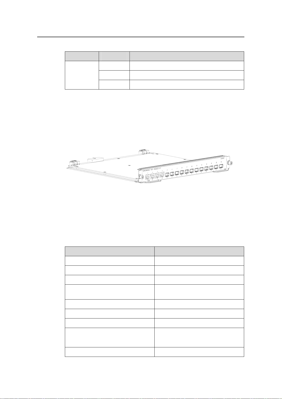
Installation Manual
H3C S7500 Series Ethernet Switches Chapter 2 Line Processing Units
Table 2-24 LED description of the LS81T12PE
LED Status Meaning
LINK/ACT
2.12.3 Matching Cable
Refer to section 2.11 “LS81T12P“ on page 2-21.
2.13 LS81P12T
Figure 2-34 LS81P12T appearance
OFF
ON
Blinking
No link is present.
A link is present.
Data is being transmitted/received.
2.13.1 Technical Specifications
The LS81P12T provides twelve 1000Base-X-SFP ports operating in the full duplex
mode and four autosensing 10/100/1000 Base-T Ethernet ports.
Table 2-25 LS81P12T specifications
Item Specification
CPU MPC8241, 200 MHz
Boot ROM 512 KB
SDRAM 128 MB
Dimensions (H x W x D)
Maximum power consumption 31 W
Connector RJ-45, LC
Number of ports 16
Port speed
40.1 × 376.7 × 354.5 mm (1.6 × 14.8 ×
14 in.)
z 1000 Mbps full-duplex (optical)
z 10/100/1000 Mbps
half-duplex/full-duplex (electrical)
SFP modules Refer to Table 2-22
2-27
Page 63
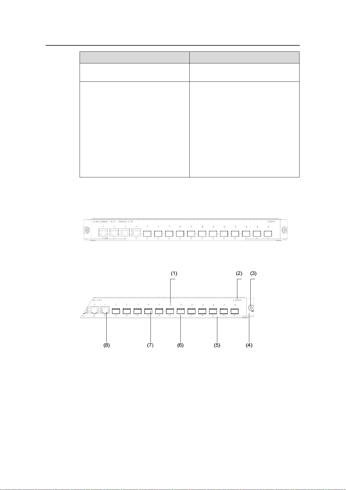
Installation Manual
H3C S7500 Series Ethernet Switches Chapter 2 Line Processing Units
Item Specification
Matching cable and maximum
transmission distance
Compliant standard
2.13.2 Panel and LEDs
Category-5 twisted pair, with a maximum
transmission distance of 100 m (328.1 ft)
z IEEE 802.3
z IEEE 802.3u
z IEEE 802.3z
z IEEE 802.3ab
z IEEE 802.1p
z IEEE 802.1Q
z IEEE 802.1D
z IEEE 802.1X
z IEEE 802.1s
z IEEE 802.1w
z IEEE 802.3x
z IEEE 802.3ad
Figure 2-35 LS81P12T panel
(1) Port number (2) Silkscreen of the LPU name
(3) Captive screw (4) LPU edge (purple)
(5) Ejector lever (6) 1000Base-X-SFP port status LED
(7) 1000Base-X-SPF port (8) 10/100/1000Base-T Ethernet port
Figure 2-36 Partially amplified view of the LS81P12T panel
The following table describes the LED.
2-28
Page 64

Installation Manual
H3C S7500 Series Ethernet Switches Chapter 2 Line Processing Units
Table 2-26 LED description of the LS81P12T
LED Status Meaning
LINK/ACT
2.13.3 Matching Cable
Refer to section 2.11.3 “Matching Cable” on page 2-23.
2.14 LS81P12TE
Figure 2-37 LS81P12TE appearance
OFF
ON
Blinking
No link is present.
A link is present.
Data is being transmitted/received.
2.14.1 Technical Specifications
The LS81P12TE can serve as the SRPU of the S7502.
Table 2-27 LS81P12TE specifications
Item Specification
CPU MPC8245, 300 MHz
Boot ROM 512 KB
Flash memory 32 MB
SDRAM 256 MB
Dimensions (H x W x D) 40.1 × 376.7 × 354.5 mm (1.6 × 14.8 × 14 in.)
Number of ports
Maximum power consumption 40 W
Port speed
z Four 10/100/1000BASE-T Ethernet ports
z Twelve 1000BASE-X-SFP ports
z 1000 Mbps full-duplex (optical port)
z 10 Mbps half-duplex/full-duplex (electrical
port)
z 100 Mbps half-duplex/full-duplex (electrical
port)
z 1000 Mbps full-duplex (electrical port)
2-29
Page 65

Installation Manual
H3C S7500 Series Ethernet Switches Chapter 2 Line Processing Units
Item Specification
SFP modules Refer to Table 2-22
Matching cable and maximum
transmission distance
Compliant standard
2.14.2 Panel and LEDs
The LS81P12TE provides four 10/100/1000BASE-T Ethernet ports and twelve
1000BASE-X-SFP ports and each port has a status LED.
Category-5 twisted pair cable, with a maximum
transmission distance of 100 m (328.1 ft)
z IEEE 802.3
z IEEE 802.3u
z IEEE 802.3z
z IEEE 802.3ab
z IEEE 802.1p
z IEEE 802.1Q
z IEEE 802.1D
z IEEE 802.1X
z IEEE 802.1s
z IEEE 802.1w
z IEEE 802.3x
z IEEE 802.3ad
Figure 2-38 LS81P12TE panel
(1) Port number (2) Silkscreen of the LPU name
(3) Captive screw (4) LPU edge (green)
(5) Ejector lever (6) Port status LED
(7) SPF port (Gigabit) (8) Ethernet port (Gigabit)
Figure 2-39 Partially amplified view of the LS81P12TE panel
For the description of the LED of the LS81P12TE, see
Table 2-26.
2-30
Page 66

Installation Manual
H3C S7500 Series Ethernet Switches Chapter 2 Line Processing Units
2.14.3 Matching Cable
Refer to section 2.11 “LS81T12P” on page 2-21.
2.15 LS81T16P
Figure 2-40 LS81T16P appearance
2.15.1 Technical Specifications
The LS81T16P adopts an XG high-speed bus. It can also serve as the SRPU of the
S7502.
Table 2-28 LS81T16P specifications
Item Specification
CPU MPC8245, 300M
BOOT ROM 512 KB
Flash memory 32 MB
SDRAM 256 MB
Dimensions (W x D) 366.7 x 340 mm (14.4 x 13.4 in.)
z Sixteen autosensing
Number of ports
10/100/1000Base-T Ethernet ports
z Eight 1000Base-X-SFP ports
Maximum power consumption 55 W
Connector RJ-45, LC
Number of ports 24
z 10 Mbps half-duplex/full-duplex
Port speed
z 100 Mbps half-duplex/full-duplex
z 1000 Mbps full-duplex
z MDI/MDI-X autosensing
SFP module Refer to Table 2-22.
Matching cable and maximum
transmission distance
2-31
Category-5 twisted pair, with a maximum
transmission distance of 100 m (328.1 ft)
Page 67

Installation Manual
H3C S7500 Series Ethernet Switches Chapter 2 Line Processing Units
Item Specification
z IEEE 802.3
z IEEE 802.3u
z IEEE 802.3z
z IEEE 802.3ab
z IEEE 802.1p
Compliant standard
z IEEE 802.1Q
z IEEE 802.1D
z IEEE 802.1X
z IEEE 802.1s
z IEEE 802.1w
z IEEE 802.3x
z IEEE 802.3ad
Note:
When using the LS81T16P as an LPU of the S7503/S7506/S7506R, you can only use it
together with a Salience III or Salience III Plus SRPU.
z If you use the LS81T16P together with a Salience III Plus SRPU, you can insert it
into any LPU slot on the S7503/S7506/S7506R.
z If you use the LS81T16P together with a Salience III SRPU, you can only insert it
into one of the last two LPU slots on the S7503/S7506/S7506R (slot 2 or 3 for the
S7503, slot 5 or 6 for the S7506, and slot 6 or 7 for S7506R).
2.15.2 Panel and LEDs
Figure 2-41 LS81T16P panel
2-32
Page 68

Installation Manual
H3C S7500 Series Ethernet Switches Chapter 2 Line Processing Units
(1) Silkscreen of the LPU name (2) Captive screw
(3) LPU edge (green) (4) Ejector lever
(5) 1000Base-X-SPF port (6) 1000Base-X-SFP port status LED
(7) 10/100/1000Base-T Ethernet port
Figure 2-42 Partially amplified view of the LS81T16P panel
The following table describes the LED of the LS81T16P:
Table 2-29 LED description of the LS81T16P
LED Status Meaning
LINK/ACT
2.15.3 Matching Cable
Refer to section 2.11 “LS81T12P” on page 2-21..
2.16 LS81T32P
OFF
ON
Blinking
No link is present.
A link is present.
Data is being transmitted/received.
Figure 2-43 LS81T32P appearance
2.16.1 Technical Specifications
The LS81T32P adopts an XG high-speed bus. It can also serve as the SRPU of the
S7502.
2-33
Page 69

Installation Manual
H3C S7500 Series Ethernet Switches Chapter 2 Line Processing Units
Table 2-30 LS81T32P specifications
Item Specification
CPU MPC8245, 300 MHz
BOOT ROM 512 KB
Flash memory 32 MB
SDRAM 256 MB
Dimensions (H x W x D)
Number of ports
40.1 × 376.7 × 354.5 mm (1.6 × 14.8 ×
14 in.)
z Thirty-two autosensing
10/100/1000Base-T Ethernet ports
z Sixteen 1000Base-X-SFP ports
Maximum power consumption 93 W
Connector RJ-45, LC
z 10 Mbps half-duplex/full-duplex
Port speed
z 100 Mbps half-duplex/full-duplex
z 1000 Mbps full-duplex
z MDI/MDI-X autosensing
SFP modules Refer to Table 2-22.
Matching cable and maximum
transmission distance
Compliant standard
Category-5 twisted pair, with a maximum
transmission distance of 100 m (328.1 ft)
z IEEE 802.3
z IEEE 802.3u
z IEEE 802.3z
z IEEE 802.3ab
z IEEE 802.1p
z IEEE 802.1Q
z IEEE 802.1D
z IEEE 802.1X
z IEEE 802.1s
z IEEE 802.1w
z IEEE 802.3x
z IEEE 802.3ad
2-34
Page 70

Installation Manual
H3C S7500 Series Ethernet Switches Chapter 2 Line Processing Units
Note:
When using the LS81T32P as an LPU of the S7503/S7506/S7506R switch, you can
only use it together with a Salience III or Salience III Plus SRPU.
z If you use the LS81T32P together with a Salience III Plus SRPU, you can insert it
into any LPU slot on the S7503/S7506/S7506R.
z If you use the LS81T32P together with a Salience III SRPU, you can only insert it
into one of the last two LPU slots on the S7503/S7506/S7506R (slot 2 or 3 for the
S7503, slot 5 or 6 for the S7506, and slot 6 or 7 for the S7506R).
2.16.2 Panel and LEDs
Figure 2-44 LS81T32P panel
(1) Silkscreen of the LPU name (2) Captive screw
(3) LPU edge (green) (4) Ejector lever
(5) 1000Base-X-SFP port status LED (6) 1000Base-X-SPF port
(7) 10/100/1000Base-T Ethernet port
Figure 2-45 Partially amplified view of the LS81T32P panel
The following table describes the LED of the LS81T32P:
2-35
Page 71

Installation Manual
H3C S7500 Series Ethernet Switches Chapter 2 Line Processing Units
Table 2-31 LED state description of LS81T32P
LED Status Meaning
LINK/ACT
2.16.3 Matching Cable
Refer to section 2.11 “LS81T12P” on page 2-21.
2.17 LS81GP8UB
Figure 2-46 LS81GP8UB appearance
OFF
ON
Blinking
No link is present.
A link is present.
Data is being transmitted/received.
2.17.1 Technical Specifications
The LS81GP8UB provides eight 1000Base-X-SFP ports operating in the full-duplex
mode.
Table 2-32 LS81GP8UB specifications
Item Specification
CPU MPC850, 50 MHz
Boot ROM 512 KB
SDRAM 64M
Dimensions (H x W x D) 40.1 × 376.7 × 354.5 mm (1.6 × 14.8 × 14 in.)
Maximum power consumption 9.5 W
Connector LC, RJ-45
Number of ports 8
Port speed 1000 Mbps full-duplex
SFP modules Refer to Table 2-22
2-36
Page 72

Installation Manual
H3C S7500 Series Ethernet Switches Chapter 2 Line Processing Units
Item Specification
z IEEE 802.3
z IEEE 802.3z
z IEEE 802.1p
z IEEE 802.1Q
Compliant standard
z IEEE 802.1D
z IEEE 802.3x
z IEEE 802.3ad
z IEEE 802.1X
z IEEE 802.1s
z IEEE 802.1w
Note:
z The LS81GP8UB can only be used together with a Salience III and Salience III
Edge SRPU.
z If a Salience III or Salience III Edge SRPU is used, the LS81GP8UB cannot be
inserted in the last LPU slot of the S7506 or the S7506R (slot 6 for the S7506 and
slot 7 for the S7506R), but can be inserted in any LPU slot of the S7503.
2.17.2 Panel and LEDs
Figure 2-47 LS81GP8UB panel
2-37
Page 73

Installation Manual
H3C S7500 Series Ethernet Switches Chapter 2 Line Processing Units
(1) Port number (2) Silkscreen of the LPU name
(3) Captive screw (4) LPU edge (purple)
(5) Ejector lever (6) 1000Base-X-SFP port status LED
(7) 1000Base-X-SFP port
Figure 2-48 Partially amplified view of the LS81GP8UB panel
The following table describes the LED of the LS81GP8UB.
Table 2-33 LED description of the LS81GP8UB
LED Status Meaning
LINK/ACT
2.17.3 Matching Cable
Refer to Table 2-22 in section 2.11.3 "Matching Cable" on page 2-23.
2.18 LS82GP20
Figure 2-49 LS82GP20 appearance
OFF
ON
Blinking
No link is present.
A link is present.
Data is being transmitted/received.
2.18.1 Technical Specifications
The LS82GP20 provides twenty 1000Base-X-SFP ports operating in the full-duplex
mode.
2-38
Page 74
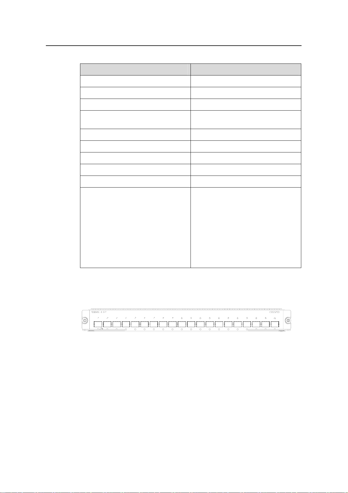
Installation Manual
H3C S7500 Series Ethernet Switches Chapter 2 Line Processing Units
Table 2-34 LS82GP20 specifications
Item Specification
CPU MPC8241, 200 MHz
Boot ROM 512 KB
SDRAM 64 MB
Dimensions (H x W x D)
40.1 × 376.7 × 354.5 mm (1.6 × 14.8 ×
14 in.)
Maximum power consumption 35 W
Connector LC
Number of ports 20
Port speed 1000 Mbps full-duplex
SFP modules Refer to Table 2-22
z IEEE 802.3
z IEEE 802.3z
z IEEE 802.1p
z IEEE 802.1Q
Compliant standard
z IEEE 802.1D
z IEEE 802.3x
z IEEE 802.1X
z IEEE 802.1w
z IEEE 802.3ad
z IEEE 802.1s
2.18.2 Panel and LEDs
Figure 2-50 LS82GP20 panel
2-39
Page 75

Installation Manual
H3C S7500 Series Ethernet Switches Chapter 2 Line Processing Units
(1) Port number (2) Silkscreen of the LPU name
(3) Captive screw (4) LPU edge (purple)
(5) Ejector lever (6) 1000Base-X-SFP port
(7) 1000Base-X-SFP port status LED
Figure 2-51 Partially amplified view of the LS82GP20 panel
The following table describes the LED of the LS82GP20.
Table 2-35 LED description of the LS82GP20
LED Status Meaning
LINK/ACT
2.18.3 Matching Cable
Refer to Table 2-22 in section 2.11.3 "Matching Cable" on page 2-23.
2.19 LS82GP20A
Figure 2-52 LS82GP20A appearance
OFF
ON
Blinking
No link is present.
A link is present.
Data is being transmitted/received.
2.19.1 Technical Specifications
The LS82GP20A provides twenty 1000Base-X-SFP ports operating in the full-duplex
mode.
2-40
Page 76

Installation Manual
H3C S7500 Series Ethernet Switches Chapter 2 Line Processing Units
Table 2-36 LS82GP20A specifications
Item Specification
CPU MPC8241, 200 MHz
Boot ROM 512 KB
SDRAM 128 MB
Dimensions (H x W x D)
40.1 × 376.7 × 354.5 mm (1.6 × 14.8 ×
14 in.)
Maximum power consumption 35 W
Connector LC
Number of ports 20
Port speed 1000 Mbps full-duplex
SFP modules Refer to Table 2-22
z IEEE 802.3
z IEEE 802.3z
z IEEE 802.1p
z IEEE 802.1Q
Compliant standard
z IEEE 802.1D
z IEEE 802.3x
z IEEE 802.1X
z IEEE 802.1w
z IEEE 802.3ad
z IEEE 802.1s
2.19.2 Panel and LEDs
Figure 2-53 LS82GP20A panel
2-41
Page 77
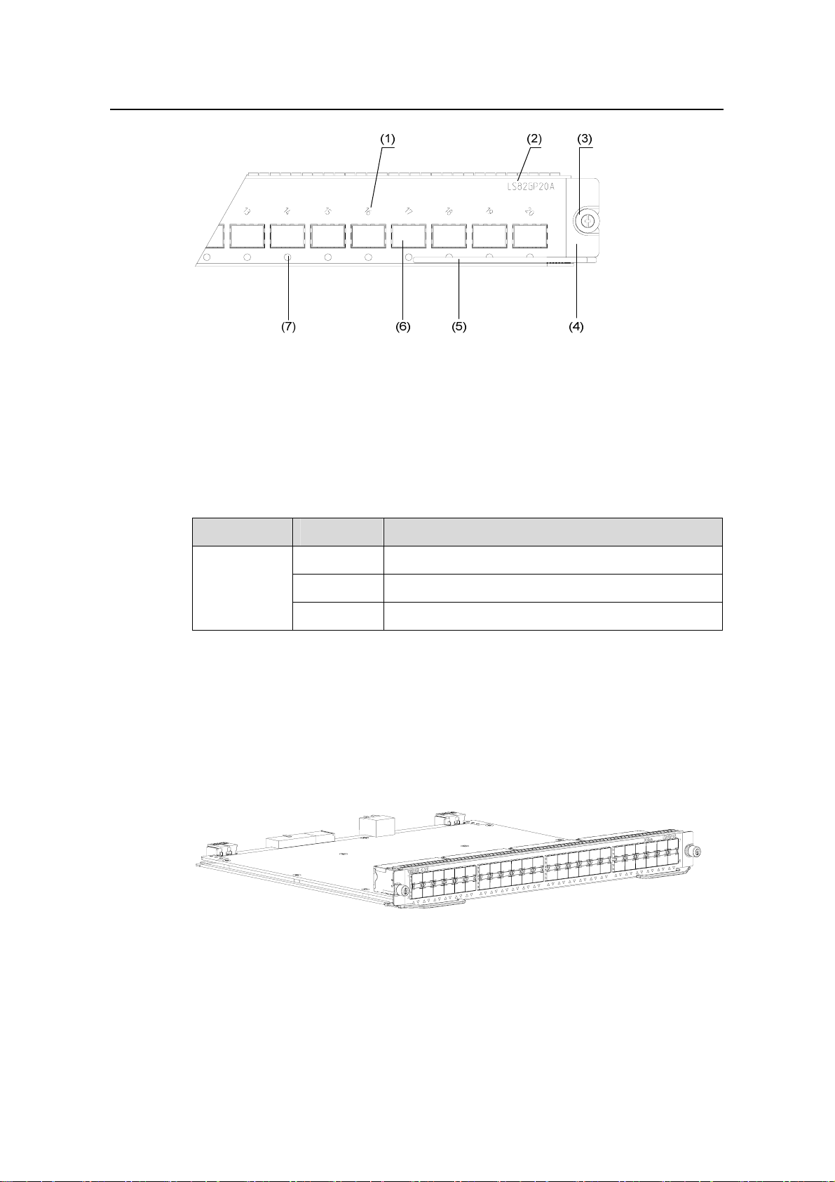
Installation Manual
H3C S7500 Series Ethernet Switches Chapter 2 Line Processing Units
(1) Port number (2) Silkscreen of the LPU name
(3) Captive screw (4) LPU edge (purple)
(5) Ejector lever (6) 1000Base-X-SFP port
(7) 1000Base-X-SFP port status LED
Figure 2-54 Partially amplified view of the LS82GP20A panel
The following table describes the LED of the LS82GP20A.
Table 2-37 LED description of the LS82GP20A
LED Status Meaning
LINK/ACT
2.19.3 Matching Cable
Refer to Table 2-22 in section “Matching Cable” on page 2-23.
2.20 LS81GP48
OFF
ON
Blinking
No link is present.
A link is present.
Data is being transmitted/received.
Figure 2-55 LS81GP48 appearance
2-42
Page 78

Installation Manual
H3C S7500 Series Ethernet Switches Chapter 2 Line Processing Units
2.20.1 Technical Specifications
The LS81GP48 adopts an XG high-speed bus and provides forty-eight
1000Base-X-SFP ports operating in the full-duplex mode. It can also serve as the
SRPU of the S7502.
Table 2-38 LS81GP48 specifications
Item Specification
CPU MPC8245, 300 MHz
BOOT ROM 512 KB
Flash memory 32 MB
SDRAM 256 MB
Dimensions (H x W x D)
40.1 × 376.7 × 354.5 mm (1.6 × 14.8 ×
14 in.)
Maximum power consumption 75 W
Connector LC
Number of ports 48
Port speed z 1000 Mbps full-duplex
SFP modules Refer to Table 2-22.
z IEEE 802.3
z IEEE 802.3z
z IEEE 802.1p
z IEEE 802.1Q
Compliant standard
z IEEE 802.1D
z IEEE 802.3x
z IEEE 802.1X
z IEEE 802.1w
z IEEE 802.3ad
z IEEE 802.1s
Note:
When using the LS81GP48 as an LPU of the S7503/S7506/S7506R, you can only use
it together with a Salience III or Salience III Plus SRPU.
z If you use the LS81GP48 together with a Salience III Plus SRPU, you can insert it
into any LPU slot on the S7503/S7506/S7506R.
z If you use the LS81GP48 together with a Salience III SRPU, you can only insert it
into one of the last two LPU slots on the S7503/S7506/S7506R (slot 2 or 3 for the
S7503, slot 5 or 6 for the S7506, and slot 6 or 7 for the S7506R).
2-43
Page 79
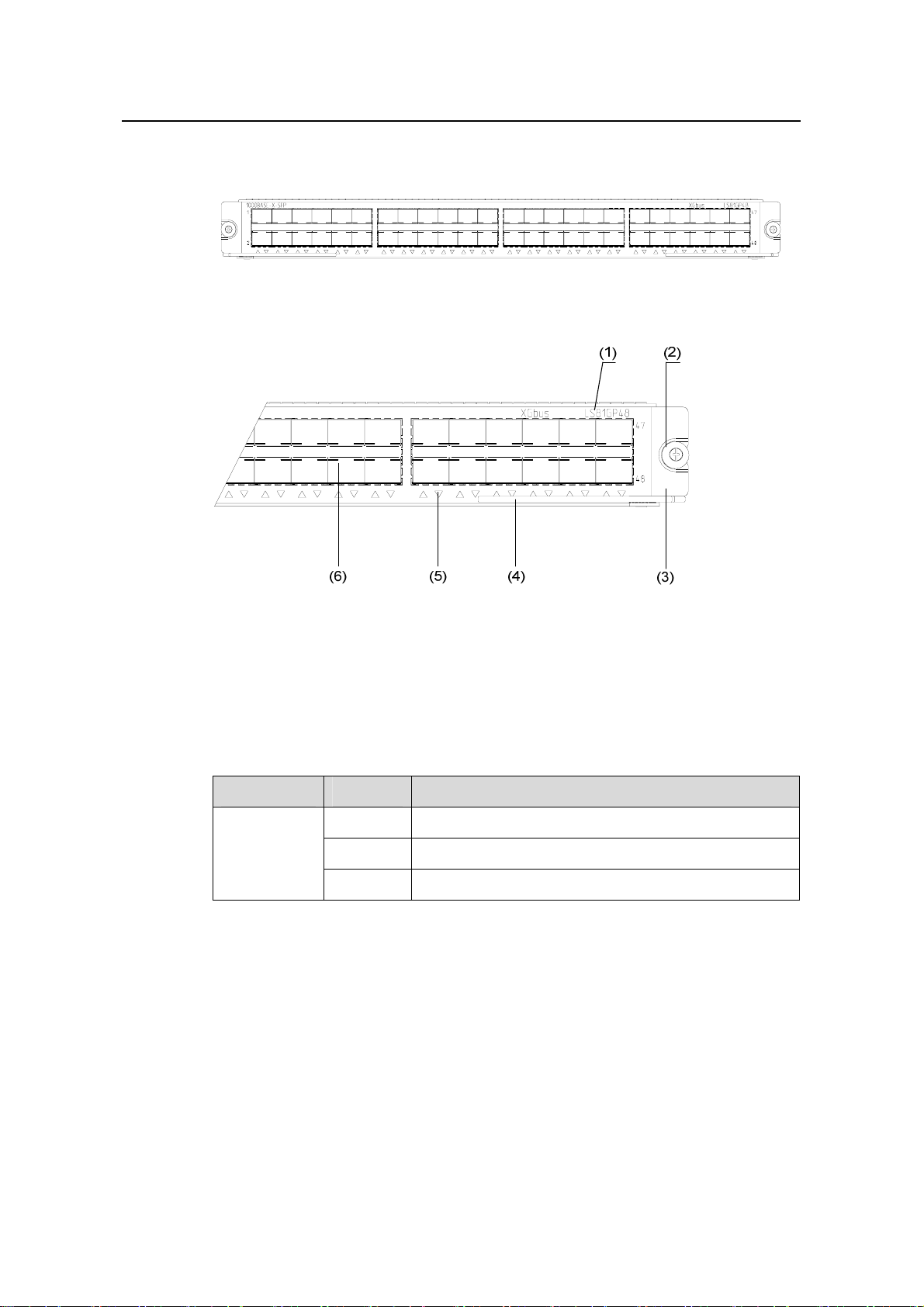
Installation Manual
H3C S7500 Series Ethernet Switches Chapter 2 Line Processing Units
2.20.2 Panel and LEDs
Figure 2-56 LS81GP48 panel
(1) Silkscreen of the LPU name (2) Captive screw
(3) LPU edge (green) (4) Ejector lever
(5) 1000Base-X-SFP port status LED (6) 1000Base-X-SFP port
Figure 2-57 Partially amplified view of the LS81GP48 panel
The following table describes the LED of the LS81GP48:
Table 2-39 LED description of the LS81GP48
LED Status Meaning
LINK/ACT
2.20.3 Matching Cable
Refer to Table 2-22 in section 2.11.3 "Matching Cable" on page 2-23.
OFF
ON
Blinking
No link is present.
A link is present.
Data is being transmitted/received.
2-44
Page 80

Installation Manual
H3C S7500 Series Ethernet Switches Chapter 2 Line Processing Units
2.21 LS81TGX1C
Figure 2-58 LS81TGX1C appearance
2.21.1 Technical Specifications
The LS81TGX1C provides one 10GBase-R-XENPAK port operating the full-duplex
mode.
Table 2-40 LS81TGX1C specifications
Item Specification
CPU MPC8245, 300 MHz
Boot ROM 512 KB
SDRAM 64 MB
Dimensions (H x W x D) 40.1 × 376.7 × 354.5 mm (1.6 × 14.8 × 14 in.)
Maximum power consumption 35 W
Connector SC
Number of ports 1
Port speed 10 Gbps full-duplex
z XENPAK-SX-MM850 (multimode optical
fiber, 850 nm, 300 m [984 ft])
XENPAK modules
z XENPAK-LX-SM1310 (single mode optical
fiber, 1310 nm, 10 km [6.2 mi])
z XENPAK-LH40-SM1550 (single mode
optical fiber, 1550 nm, 40 km [24.9 mi])
z IEEE 802.3
z IEEE 802.3ae
z IEEE 802.1p
z IEEE 802.1Q
Compliant standard
z IEEE 802.1D
z IEEE 802.3x
z IEEE 802.3ad
z IEEE 802.1X
z IEEE 802.1s
z IEEE 802.1w
2-45
Page 81

Installation Manual
H3C S7500 Series Ethernet Switches Chapter 2 Line Processing Units
2.21.2 Panel and LEDs
Figure 2-59 LS81TGX1C panel
(1) 10GBase-R-XENPAK port status LED
(LINK)
(3) Silkscreen of the LPU (4) Captive screw
(5) LPU edge (green) (6) Ejector lever
(7) 10GBase-R-XENPAK port (8) Captive screw
(2) 10GBase-R-XENPAK port status LED
(ACT)
Figure 2-60 Partially amplified view of the LS81TGX1C panel
The following table describes the LEDs of the LS81TGX1C.
Table 2-41 LED state description of LS81TGX1C
LED Status Meaning
OFF
No link is present.
LINK
ON
OFF
A link is present.
No data is being transmitted/received.
ACT
Blinking Data is being transmitted/received.
2-46
Page 82

Installation Manual
H3C S7500 Series Ethernet Switches Chapter 2 Line Processing Units
2.21.3 Matching Cable
Table 2-42 Cables for the LS81TGX1C
XENPAK module
XENPAK-SX-MM850 850 nm
XENPAK-LX-SM1310 1310 nm 10 km (6 mi)
XENPAK-LH40-SM1550 1550 nm
2.22 LS81TGX2
Figure 2-61 LS81TGX2 appearance
Central
wavelen
gth
Connect
or
SC
Matching
cable
Multimode
fiber
9µm/125µm
single mode
fiber
Maximum
transmission
distance
300 m (984 ft)
40 km (25 mi)
2.22.1 Technical Specifications
The LS81TGX2 adopts an XG high-speed bus and provides two 10GBase-XFP ports
operating in the full-duplex mode. It can also serve as the SRPU of the S7502.
Table 2-43 LS81TGX2 specifications
Item Specification
CPU MPC8245, 300 MHz
BOOT ROM 512 KB
Flash memory 32 MB
SDRAM 256 MB
Dimensions (H x W x D)
Maximum power consumption 38 W
Connector LC
Number of ports 2
Port speed 10 Gbps full-duplex
40.1 × 376.7 × 354.5 mm (1.6 × 14.8 ×
14 in.)
2-47
Page 83

Installation Manual
H3C S7500 Series Ethernet Switches Chapter 2 Line Processing Units
Item Specification
z XFP-SX-MM850 (850 nm multi-mode
fiber with a maximum transmission
distance of 300 m [984.3 ft]).
z XFP-LX-SM1310 (1,310 nm
single-mode fiber with a maximum
transmission distance of 10 km [6.2
mi])
XFP modules
z XFP-LH40-SM1550 (1,550 nm
single-mode fiber with a maximum
transmission distance of 40 km [24.9
mi])
z XFP-LH80-SM1550(1,550 nm
single-mode fiber with a maximum
transmission distance of 80 km [49.7
mi])
z IEEE 802.3
z IEEE 802.3ae
z IEEE 802.1p
z IEEE 802.1Q
Compliant standard
z IEEE 802.1D
z IEEE 802.3x
z IEEE 802.3ad
z IEEE 802.1X
z IEEE 802.1s
z IEEE 802.1w
Note:
When using the LS81TGX2 as an LPU of the S7503/S7506/S7506R, you can only use
it together with a Salience III or Salience III Plus SRPU.
z If you use the LS81TGX2 together with a Salience III Plus SRPU, you can insert it
into any LPU slot on the S7503/S7506/S7506R.
z If you use the LS81TGX2 together with a Salience III SRPU, you can only insert it
into one of the last two LPU slots on the S7503/S7506/S7506R (slot 2 or 3 for the
S7503, slot 5 or 6 for the S7506, and slot 6 or 7 for the S7506R).
2.22.2 Panel and LEDs
Figure 2-62 LS81TGX2 panel
2-48
Page 84

Installation Manual
H3C S7500 Series Ethernet Switches Chapter 2 Line Processing Units
(1) 10GBase-XFP port number (2) 10GBase-XFP port status LED (LINK)
(3) 10GBase-XFP port status LED (ACT) (4) Silkscreen of the LPU name
(5) Captive screw (6) LPU edge (green)
(7) Ejector lever (8) 10GBase-XFP port
Figure 2-63 Partially amplified view of the LS81TGX2 panel
The following table describes the LEDs of the LS81TGX2:
Table 2-44 LED description of the LS81TGX2
LED State
LINK
ACT
2.22.3 Matching Cable
Table 2-45 Cables for the LS81TGX2
XFP module
XFP-SX-MM850 850 nm
XFP-LX-SM1310 1,310 nm
XFP-LH40-SM15
50
XFP-LH80-SM15
50
OFF No link is present.
ON A link is present.
OFF No data is being transmitted/received.
Blinking Data is being transmitted/received.
Central
wavelength
Connector
Matching
cable
50 µm/125 µm
multi-mode
optical fiber
LC
9 µm/125 µm
1510 nm
single-mode
optical fiber
1510 nm
Maximum
transmissio
n distance
300 m (984.3
ft)
10 km (6.2
mi)
40 km (24.9
mi)
80 km (49.7
mi)
2-49
Page 85

Installation Manual
H3C S7500 Series Ethernet Switches Chapter 2 Line Processing Units
2.23 LS81TGX4
Figure 2-64 LS81TGX4 appearance
2.23.1 Technical Specifications
The LS81TGX4 adopts an XG high-speed bus and provides four 10GBase-XFP ports
operating in the full-duplex mode. It can also serve as the SRPU of the S7502.
Table 2-46 LS81TGX4 specifications
Item Specification
CPU MPC8245, 300 MHz
BOOT ROM 512 KB
Flash memory 32 MB
SDRAM 256 MB
Dimensions (H x W x D)
40.1 × 376.7 × 354.5 mm (1.6 × 14.8 ×
14 in.)
Maximum power consumption 54 W
Connector LC
Number of ports 4
Port speed z 10 Gbps full-duplex
z XFP-SX-MM850 (850 nm multi-mode
fiber with a maximum transmission
distance of 300 m [984.3 ft])
z XFP-LX-SM1310 (1310 nm
single-mode fiber with a maximum
transmission distance of 10 km [6.2
mi])
XFP modules
z XFP-LH40-SM1550 (1550 nm
single-mode fiber with a maximum
transmission distance of 40 km [24.9
mi])
z XFP-LH80-SM1550 (1550 nm
single-mode fiber with a maximum
transmission distance of 80 km [49.7
mi])
2-50
Page 86

Installation Manual
H3C S7500 Series Ethernet Switches Chapter 2 Line Processing Units
Item Specification
z IEEE 802.3
z IEEE 802.3ae
z IEEE 802.1p
z IEEE 802.1Q
Compliant standard
z IEEE 802.1D
z IEEE 802.3x
z IEEE 802.3ad
z IEEE 802.1X
z IEEE 802.1s
z IEEE 802.1w
Note:
When using the LS81TGX4 as an LPU of the S7503/S7506/S7506R, you can only use
it together with a Salience III or Salience III Plus SRPU.
z If you use the LS81TGX4 together with a Salience III Plus SRPU, you can insert it
into any LPU slot on the S7503/S7506/S7506R.
z If you use the LS81TGX4 together with a Salience III SRPU, you can only insert it
into one of the last two LPU slots on the S7503/S7506/S7506R (slot 2 or 3 for the
S7503, slot 5 or 6 for the S7506, and slot 6 or 7 for the S7506R).
2.23.2 Panel and LEDs
Figure 2-65 LS81TGX4 panel
2-51
Page 87

Installation Manual
H3C S7500 Series Ethernet Switches Chapter 2 Line Processing Units
(1) 10GBase-XFP port number (2) 10GBase-XFP port status LED (LINK)
(3) 10GBase-XFP port status LED (ACT) (4) Silkscreen of the LPU name
(5) Captive screw (6) LPU edge (green)
(7) Ejector lever (8) 10GBase-XFP port
Figure 2-66 Partially amplified view of the LS81TGX4 panel
Refer to
Table 2-44 in section 2.22.2 "Panel and LEDs" on page 2-48 for the LED
description of the LS81TGX4.
2.23.3 Matching Cable
Refer to Table 2-45 in section 2.22.3 "Matching Cable" on page 2-49.
2.24 LS81VSNP (without Port)
Figure 2-67 LS81VSNP appearance
2.24.1 Technical Specifications
The LS81VSNP supports XG high speed bus and possesses a high-performance
network processor (NP) and CPU and can cooperate with other LPUs to provide the
following features:
z Policy routing
z Network address translation (NAT)
z NetStream
The LS81VSNP provides no port.
2-52
Page 88

Installation Manual
H3C S7500 Series Ethernet Switches Chapter 2 Line Processing Units
Table 2-47 LS81VSNP specifications
Item Specification
CPU MPC750, 350 MHz
BOOT ROM 512 KB
SDRAM 256 MB
Dimensions (H x W x D)
40.1 × 376.7 × 354.5 mm (1.6 × 14.8 ×
14 in.)
Maximum power consumption 100 W
Connector —
Number of ports 0
Note:
When using the LS81VSNP as an LPU of the S7503/S7506/S7506R, you can only use
it together with a Salience III or Salience III Plus SRPU:
z If you use the LS81VSNP together with a Salience III Plus SRPU, you can insert it
into any LPU slot on the S7503/S7506/S7506R.
z If you use the LS81VSNP together with a Salience III SRPU, you can only insert it
into one of the last two LPU slots on the S7503/S7506/S7506R (slot 2 or 3 for the
S7503, slot 5 or 6 for the S7506, and slot 6 or 7 for the S7506R).
z When serving as an LPU of the S7502, the LS81VSNP can be i nserted only into slot
1.
2.24.2 Panel and LEDs
Figure 2-68 LS81VSNP panel
The LS81VSNP provides no port.
2-53
Page 89

Installation Manual
H3C S7500 Series Ethernet Switches Table of Contents
Table of Contents
Chapter 3 Installation Preparations............................................................................................. 3-1
3.1 Safety Precautions............................................................................................................. 3-1
3.1.1 General Safety Recommendations......................................................................... 3-1
3.1.2 Electrical Safety.......................................................................................................3-1
3.1.3 Handling Safety.......................................................................................................3-1
3.1.4 ESD Damage Prevention........................................................................................ 3-2
3.1.5 Laser Safety............................................................................................................3-3
3.2 Examining the Installation Site...........................................................................................3-3
3.2.1 Temperature/Humidity Requirements..................................................................... 3-3
3.2.2 Cleanness Requirements........................................................................................3-3
3.2.3 EMI Requirements ..................................................................................................3-4
3.2.4 Grounding Requirements........................................................................................3-4
3.2.5 Power Supply Requirements...................................................................................3-4
3.3 Installation Planning........................................................................................................... 3-5
3.3.1 Installation Space Requirement.............................................................................. 3-5
3.3.2 Cabinet-Mounting Requirements ............................................................................ 3-5
3.4 Installation Tools................................................................................................................3-6
i
Page 90

Installation Manual
H3C S7500 Series Ethernet Switches Chapter 3 Installation Preparations
Chapter 3 Installation Preparations
3.1 Safety Precautions
To avoid bodily injury and device damage, please read the following safety
recommendations carefully before installing the S7500 series. The recommendations
do not cover every possible hazardous condition.
3.1.1 General Safety Recommendations
z Keep the chassis clean and dust-free.
z Keep the chassis and installation tools away from walk areas.
z Do not wear loose clothing, jewelry (including ring and necklace, and so on), or
any other things that could get caught in the chassis when you install or maintain
the switch.
3.1.2 Electrical Safety
z Look carefully for possible hazards in your work area, such as un grou nde d power
extension cables, missing safety grounds, and moist floors.
z Locate the emergency power switch in the room before installation so that you can
shut the power off at once in case of an electrical accident.
z Unplug all external cables before moving the chassis.
z Avoid maintaining the equipment alone when it is powered by electricity.
z Never assume that power is disconnected from a circuit. Always check.
z Do not place the switch on a moist area or let liquid flow into it.
3.1.3 Handling Safety
Since the S7500 series are rather large and heavy, you should follow the
recommendations below.
z Disconnect all power and all external cables (including power cables) before
carrying or moving the chassis.
z Ask somebody to move the switch together.
z Move the switch slowly and stably.
z Keep in step with your partner and balance your bodies when moving the switch.
3-1
Page 91

Installation Manual
H3C S7500 Series Ethernet Switches Chapter 3 Installation Preparations
Caution:
Never attempt to lift the chassis by holding the handles on the power modules, or
ventilation holes because they were not designed to support the weight of the chassis.
Otherwise, device damage or even bodily injury may occur.
3.1.4 ESD Damage Prevention
To prevent electronic components of the switch from being damaged by electrostatic
discharge (ESD), you should not only take measures against ESD damage where the
switch is located, but also take the following precautions:
z Always wear an ESD-preventive wrist strap when installing components,
especially boards of the switch.
z Hold the bottom or ejector levers when installing or removing a board. Do not
touch any electronic component or PCB.
Take the following steps to use the ESD-preventive wrist strap.
1) Wear the ESD-preventive wrist strap and ensure it makes good skin contact.
2) Insert one end of the ESD-preventive wrist strap into the ESD-preventive wrist
strap hole in the switch chassis or use an alligator clip to attach the other end to
the grounding screw on the chassis, making sure that the ESD-preventive wrist
strap is well grounded.
Note:
An ESD-preventive wrist strap is shipped with the S7500 series.
There is an ESD-preventive wrist strap hole above the SRPU slot in the S7500 series
switch chassis. The grounding screw is located on the power distribution box at the
bottom rear of the chassis.
Caution:
For the safety purpose, check the resistance of the ESD-preventive wrist strap, which
should be between 1 to 10 Megohm.
3-2
Page 92

Installation Manual
H3C S7500 Series Ethernet Switches Chapter 3 Installation Preparations
3.1.5 Laser Safety
Some LPUs of the S7500 series have optical port s. If such an LPU is operating, d o not
stare into open optical ports because laser beams emitted from these optical ports will
produce high energy, which may hurt your eyes.
3.2 Examining the Installation Site
The S7500 series are designed for indoor installation. To ensure the normal operation
of the switch and prolong its service life, you should make the installation environment
meet the requirements below.
3.2.1 Temperature/Humidity Requirements
To ensure the normal operation and service life of a switch, the temperature and
humidity in the equipment room should maintain at a certain level. A long-term high
relative humidity will quite likely result in poor insulation performance, electric le akage,
mechanical property change, and corrosion, while a low relative humidity will result in
looseness of fastening screws owing to shrinkage of insulatio n washers, or electrostatic
discharge (ESD), which may damage the circuitry on the switch. A high temperature will
speed up the aging of insulation materials, and thus will greatly lower the reliability of
the switch and shorten the service life.
Table 3-1 Temperature/humidity requirements
Specification Range
Operating temperature 0°C to 45°C (32°F to 113 °F)
Relative humidity (noncondensing) 10% to 90%
3.2.2 Cleanness Requirements
Dust is harmful to the normal operation of the switch. Dust on the chassis may result in
static adsorption, which causes poor contact betwe en metal connec tors or points. Poor
contact may not only shorten the service life of the switch, but also bring about
communication failures. Especially under the condition of a low indoor humidity, dust
adsorption is apt to occur.
Table 3-2 lists the requirements on dust content limit and diameters in the equipment
room.
3-3
Page 93
Installation Manual
H3C S7500 Series Ethernet Switches Chapter 3 Installation Preparations
Table 3-2 Limitation on dust content and diameters in the equipment room
Mechanical active material Content limit (particles/m³)
Dust particle ≤3 x 10⁴ (No visible dust on desk over three days)
Note: Dust particle diameter ≥ 5µm
Besides, the contents of salt, acid, and sulfide in equipment room shall be strictly
restricted. Harmful gases will accelerate the corrosion and aging of metal parts.
3-3 lists the content limit of SO
, H2S, NH3, and CI2 in the equipment room.
2
Table
Table 3-3 Content limits on some harmful gases in the equipment room
Gas Maximum (mg/m3)
SO
2
H2S 0.006
NH
3
Cl
2
3.2.3 EMI Requirements
All possible interference sources, external or internal, affect the switch in the way of
capacitance coupling, inductance coupling, electromagnetic radiation, and common
impedance (including the grounding system) coupling. To minimize the influence of
interference sources on the switch, you should take the following into consideration:
z Take effective measures to protect the power supply system against the power
grid interference.
z Separate the protection ground (PGND) of the switch from the grounding device or
lightning protection grounding device of the power supply equipment as far as
possible.
z Keep the switch far away from radio stations, radar, and high-frequency devices
working in high currents. If necessary, adopt electromagnetic shielding.
0.2
0.05
0.01
3.2.4 Grounding Requirements
A good grounding system is the basis for a switch to work stably and reliably and the
important guarantee of lightning protection, anti-interference and ESD. You should
provide a good grounding system for the switch.
3.2.5 Power Supply Requirements
The S7500 series adopt N+1 power supply redundancy (N is 1 or 2).
3-4
Page 94

Installation Manual
H3C S7500 Series Ethernet Switches Chapter 3 Installation Preparations
1) AC power module parameters:
z Rated voltage range: 100 to 240 VAC, 50/60Hz
z Input voltage range: 90 to 264 VAC, 50/60Hz
z Maximum output power: 450 W
2) DC power module parameters:
z Rated voltage range: –48 to –60 VDC
z Input voltage range: –36 to –72 VDC
z Maximum output power: 450 W
3.3 Installation Planning
Since the S7500 series are a kind of complex equipment, it is necessary to make a
good plan and arrangement concerning installation position, networking mode, power
supply and cabling before installation.
3.3.1 Installation Space Requirement
For better heat dissipation and equipment maintenance, it is recommended that the
front and back of the switch should be at least 1 m (39.4 in.) away from walls or other
devices, and that the left and right side should be at least 0.8 m (31.5 in.) away from
walls. If the switch is to be installed in a cabinet, the headroom in the equipment room
should be 3 m (9.84 ft.) at least.
3.3.2 Cabinet-Mounting Requirements
Before mounting the switch in a cabinet, make sure the cabinet meets the following
requirements:
z Mount the switch in an open cabinet if possible. However, if you mount a switch in
a closed cabinet, make sure that the cabinet is equipped with a good heat
dissipation system.
z Make sure that the cabinet is steady enough to support the switch and
accessories.
z Make sure that the cabinet fits the switch size, and that there is clearance around
the left and right panels of the switch for heat dissipation.
3-5
Page 95

Installation Manual
H3C S7500 Series Ethernet Switches Chapter 3 Installation Preparations
3.4 Installation Tools
Table 3-4 List of required installation tools
Type Tools
General tools
Special tools
Tools for
cleaning
optical fibers
Measuring and
marking tools
Drilling tools
Long tape, ruler (1 meter long), gradienter,
marking pen, powder marker, and pencil
Percussion drill, drill bits, and vacuum cleaner
z Flat-blade screwdriver P4-75 mm
z Phillips screwdrivers P1-100 mm, P2-150 mm
and P3-250 mm
Fastening tools
z Socket wrench M5
z Box-end wrench M6
z Double box-end wrench (10×12) or double
open-end wrench (10×12)
Sharp-nose pliers, diagonal pliers, vices,
Small tools
Auxiliary tools
ESD-preventive wrist strap, cable stripper, crimping pliers, RJ-45
crimping pliers and wire punchdown tool
hand-held electric drill, file, handsaw, crowbar
and rubber hammer
Hair brush, tweezers, paper knife, hand bellows,
electric iron, solder wire, fork and ladder
Airlaid paper and fiberscope
Multimeter, 500 V Meg-ohmmeter (used to measure the insulation
Meters
resistance), bit error ratio (BER) tester, optical power meter and
earth resistance tester
Note:
None of the above meters and tools except the ESD-preventive wrist strap is shipped
with the S7500 series and you need to prepare them.
3-6
Page 96

Installation Manual
H3C S7500 Series Ethernet Switches Table of Contents
Table of Contents
Chapter 4 Hardware Installation .................................................................................................. 4-1
4.1 Confirming Installation Preparations.................................................................................. 4-1
4.2 Installation Flowchart......................................................................................................... 4-2
4.3 Mounting the Switch to the Designated Position...............................................................4-2
4.3.1 Mounting the Switch in a Cabinet............................................................................4-2
4.3.2 Mounting the Switch on a Table..............................................................................4-3
4.4 Installing Modules of the Switch ........................................................................................ 4-4
4.5 Connecting the Grounding Cable ...................................................................................... 4-4
4.6 Connecting Power Cables.................................................................................................4-6
4.6.1 Connecting the AC Power Cord..............................................................................4-6
4.6.2 Connecting the DC Power Cables .......................................................................... 4-7
4.6.3 Connecting PoE Power Cables...............................................................................4-8
4.7 Connecting Interface Cables .............................................................................................4-9
4.7.1 Connecting the Console Cable ............................................................................... 4-9
4.7.2 Connecting the AUX Cable...................................................................................4-10
4.7.3 Connecting the COM Port Cable...........................................................................4-11
4.7.4 Connecting Category-5 Cables.............................................................................4-11
4.7.5 Connecting Fibers................................................................................................. 4-13
4.8 Cabling.............................................................................................................................4-14
4.8.1 Cabling for Desk-Mounting....................................................................................4-14
4.8.2 Cabling for Cabinet-Mounting ............................................................................... 4-14
4.9 Cable Binding...................................................................................................................4-14
4.9.1 Correct Use of Labels ...........................................................................................4-14
4.9.2 Precautions for Cable Binding...............................................................................4-14
4.10 Checking the Installation................................................................................................4-17
i
Page 97

Installation Manual
H3C S7500 Series Ethernet Switches Chapter 4 Hardware Installation
Chapter 4 Hardware Installation
Note:
The S7500 series are designed for indoor installation.
4.1 Confirming Installation Preparations
Before installation, make sure that
z You have read Chapter 3 carefully
z All requirements mentioned in Chapter 3 “Installation Preparations” are satisfied.
4-1
Page 98

Installation Manual
H3C S7500 Series Ethernet Switches Chapter 4 Hardware Installation
4.2 Installation Flowchart
Start
Mount the switch to the
designated position
Install modules of the switch
Connect the grounding cable
Connect the power
cable(s)
Connect the interface cables
Route and bind the cables
Check the installation
End
Figure 4-1 Installation flowchart
4.3 Mounting the Switch to the Designated Position
4.3.1 Mounting the Switch in a Cabinet
After purchasing an S7500 series switch, you can mount the switch in an H3C N68
cabinet or a standard 19-inch cabinet. The installation methods are similar. The
following example illustrates how to mount a switch onto an N68 cabinet.
4-2
Page 99

Installation Manual
H3C S7500 Series Ethernet Switches Chapter 4 Hardware Installation
Figure 4-2 Mount the S7506 in an N68 cabinet
I. Installing an N68 cabinet
In an N68 cabinet ready for delivery , a place has b een arranged for mounting the switch
according to the order , and all accessorie s out side the switch, exce pt for the LPUs and
cables, have been installed. For the procedure for installing an N68 cabinet, refer to
Appendix B.
II. Mounting the switch
1) Before installation, make sure that:
z The N68 cabinet has been fixed and a place has been arranged for the switch,
without any obstacle in or around the cabinet.
z The switch is ready for installation and has been carried to a place near the
cabinet.
2) Mount a plate in the N68 cabinet to hold the switch.
3) Install the supplied cable management bracket and mounting bracket on the
switch.
4) Carry the switch with another person to the front of the cabinet.
5) Lift the switch a little higher than the plate, put it on the plate and adjust its location.
6) Attach the mounting bracket to the square holes in the brackets of the N68 cabinet
with screws to fix the switch on the cabinet.
4.3.2 Mounting the Switch on a Table
1) Before installation, make sure that:
z The table is firm enough to hold the switch and cables.
z There are no obstacles around the table.
4-3
Page 100

Installation Manual
H3C S7500 Series Ethernet Switches Chapter 4 Hardware Installation
2) Carry the switch with another person to the front of the table.
3) Carry the switch a little higher than the table and put the switch on the table.
4.4 Installing Modules of the Switch
Modules of the switch include boards, power modules, power distribution boxes, and
fan tray. For detailed installation procedure s, se e Chapter 7 “Hardware Maintenance”.
4.5 Connecting the Grounding Cable
Warning:
The correct connection of the protection grounding (PGND) cable of the switch is
crucial to lightning protection and electromagnetic susceptibility (EMS) of the switch.
Thus, you must connect the PGND cable properly before installing and using the
switch.
I. Under the common grounding environment
Follow these steps to connect the PGND cable under the common grounding
environment:
1) Remove the grounding screw from the switch chassis.
2) Put the supplied PGND cable terminal block through the grounding screw.
3) Fasten the grounding screw into the hole in the chassis.
4) Connect the other end of the PGND cable to the grounding strip of the switch.
Note:
Generally, the cabinet has a grounding strip. You can connect the PGND cable of the
switch to the grounding strip of the cabinet.
4-4
 Loading...