

Page 1

H3C S5500-SI Complete Series
Ethernet Switches
Hangzhou H3C Technologies Co., Ltd.
http://www.h3c.com
Installation Manual
Manual Version: 20070910-C-1.00
Page 2

Copyright © 2007, Hangzhou H3C Technologies Co., Ltd. and its licensors
All Rights Reserved
No part of this manual may be reproduced or transmitted in any form or by any means
without prior written consent of Hangzhou H3C Technologies Co., Ltd.
Trademarks
H3C, , Aolynk, , H3Care,
Neocean, NeoVTL, SecPro, SecPoint, SecEngine, SecPath, Comware, Secware,
Storware, NQA, VVG, V
HUASAN are trademarks of Hangzhou H3C Technologies Co., Ltd.
All other trademarks that may be mentioned in this manual are the property of their
respective owners.
Notice
The information in this document is subject to change without notice. Every effort has
been made in the preparation of this document to ensure accuracy of the content s, but
all statements, information, and recommendations in this document do not constitute
the warranty of any kind, express or implied.
To obtain the latest information, please access:
http://www. h3c.com
Technical Support
customer_service@h3c.com
http://www. h3c.com
, TOP G, , IRF, NetPilot,
2
G, VnG, PSPT, XGbus, N-Bus, TiGem, InnoVision and
Page 3

About This Manual
Related Documentation
In addition to this manual, each H3C S5500-SI Complete Series Ethernet Switches
documentation set includes the following:
Manual Description
Organization
H3C S5500-SI Complete Series Ethernet Switches Installation Manual is organized as
follows:
H3C S5500-SI Series Ethernet Switches
Operation Manual
H3C S5500-SI Series Ethernet Switches
Command Manual
Chapter Contents
Introduces the characteristics and technical
1 Product Overview
2 Preparing for Installation
3 Installing the Switch
specifications of S5500-SI Complete Series Ethernet
Switches.
Introduces the installation preparation and precaution
of S5500-SI Complete Series Ethernet Switches.
Introduces the procedures to install an S5500-SI
Complete Series Ethernet Switch, including the setup
of the mainframe, cards and cables.
It is used for assisting the users in data
configurations and typical applications.
It is used for assisting the users in using
various commands.
4 Powering on the Switch
for the First Time
5 BootROM and Host
Software Loading
6 Maintenance and
Troubleshooting
Appendix A Lightning
Protection of the Switch
Introduces the booting process of an S5500-SI
Complete Series Ethernet Switch, including the
power-on booting of the switch and the system
initialization.
Introduces how to load BootROM and host software
for an S5500-SI Complete Series Ethernet Switch.
Introduces the problems that might occur during the
installation and the booting of an S5500-SI Complete
Series Ethernet Switch and the related solution.
Introduces lightning protection of S5500-SI Complete
Series Ethernet Switches.
Page 4
Conventions
The manual uses the following conventions:
I. GUI conventions
Convention Description
< >
[ ]
/
Button names are inside angle brackets. For example, click
<OK>.
Window names, menu items, data table and field names
are inside square brackets. For example, pop up the [New
User] window.
Multi-level menus are separated by forward slashes. For
example, [File/Create/Folder].
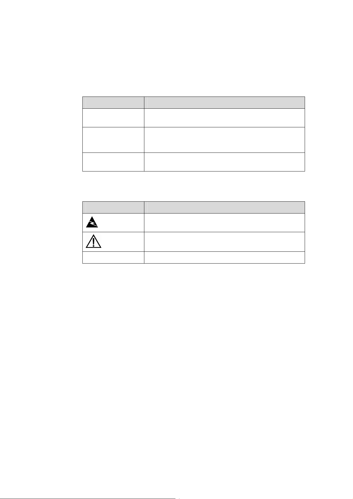
II. Symbols
Convention Description
Means reader be extremely careful. Improper operation
Warning
Caution
Note Means a complementary description.
may cause bodily injury.
Means reader be careful. Improper operation may cause
data loss or damage to equipment.
Environmental Protection
This product has been designed to comply with the requirements on environmental
protection. For the proper storage, use and disposal of this product, national laws and
regulations must be observed.
Page 5

Installation Manual
H3C S5500-SI Complete Series Ethernet Switches Table of Contents
Table of Contents
Chapter 1 Product Overview........................................................................................................1-1
1.1 Preface...............................................................................................................................1-1
1.2 Introduction to S5500-SI Series Ethernet Switches...........................................................1-3
1.2.1 S5500-28C-SI Ethernet Switch...............................................................................1-3
1.2.2 S5500-52C-SI Ethernet Switch...............................................................................1-4
1.2.3 S5500-28C-PWR-SI Ethernet Switch......................................................................1-5
1.2.4 S5500-52C-PWR-SI Ethernet Switches.................................................................. 1-7
1.2.5 S5500-20TP-SI Ethernet Switch.............................................................................1-8
1.3 Introduction to Front Panel LEDs.....................................................................................1-10
1.3.1 LEDs of S5500-28C-SI/S5500-52C-SI Switch......................................................1-10
1.3.2 LEDs of S5500-28C-PWR-SI/S5500-52C-PWR-SI Switch................................... 1-12
1.3.3 LEDs of S5500-20TP-SI Switch............................................................................1-16
1.4 System Specifications of the S5500-SI Series................................................................1-19
1.5 SFP Modules ................................................................................................................... 1-21
1.6 Optional Interface Modules..............................................................................................1-21
1.6.1 One-port 10 GE XFP Interface Module.................................................................1-22
1.6.2 Dual-Port 10 GE XFP Interface Module................................................................1-22
1.6.3 Short-haul Dual-Port 10 GE CX4 Interface Module..............................................1-23
1.6.4 Description of LEDs of Extension Modules...........................................................1-23
1.7 CX4 Cable........................................................................................................................1-23
Chapter 2 Preparing for Installation............................................................................................ 2-1
2.1 Safety Precautions............................................................................................................. 2-1
2.2 Installation Site...................................................................................................................2-1
2.2.1 Temperature/Humidity.............................................................................................2-1
2.2.2 Cleanness ............................................................................................................... 2-2
2.2.3 Electromagnetic Susceptibility ................................................................................ 2-2
2.2.4 Laser Safety............................................................................................................ 2-3
2.3 Installation Tools................................................................................................................2-3
Chapter 3 Installing the Switch....................................................................................................3-1
3.1 Rack-Mounting the Switch.................................................................................................3-1
3.1.1 Cabinet Mounting.................................................................................................... 3-1
3.1.2 Mounting the Switch on a Workbench .................................................................. 3-10
3.2 Connecting the Power Cords and the Ground Wire........................................................ 3-11
3.2.1 Connecting the AC Power Cord............................................................................3-11
3.2.2 Connecting the DC Power Cord............................................................................ 3-12
3.2.3 Connecting the Ground Wire.................................................................................3-15
3.3 Connecting Optical Fiber.................................................................................................3-17
i
Page 6

Installation Manual
H3C S5500-SI Complete Series Ethernet Switches Table of Contents
3.4 Connecting Console Cable..............................................................................................3-17
3.4.1 Console Cable....................................................................................................... 3-17
3.4.2 Connecting Console Cable ................................................................................... 3-18
3.5 Installing and Removing Optional Interface Modules...................................................... 3-19
3.5.1 10 GE XFP Interface Module................................................................................3-19
3.5.2 Short-haul Dual-port 10 GE CX4 Interface Module...............................................3-22
3.6 Installing Dedicated CX4 Cable.......................................................................................3-23
3.6.1 Installing Dedicated CX4 Cable ............................................................................ 3-23
3.6.2 Removing Dedicated CX4 Cable .......................................................................... 3-23
3.7 Verifying the Installation................................................................................................... 3-23
Chapter 4 Powering on the Switch for the First Time................................................................4-1
4.1 Setting up the Configuration Environment.........................................................................4-1
4.2 Connecting Console Cable................................................................................................4-1
4.3 Setting Terminal Parameters.............................................................................................4-1
4.4 Booting the Switch............................................................................................................. 4-5
4.4.1 Checking before Powering on the Switch ............................................................... 4-5
4.4.2 Powering on the Switch........................................................................................... 4-5
4.4.3 Changing the Startup Mode.................................................................................... 4-7
Chapter 5 Boot ROM and Host Software Loading ..................................................................... 5-1
5.1 Introduction to Loading Modes .......................................................................................... 5-1
5.2 Local Software Loading.....................................................................................................5-1
5.2.1 Boot Menu...............................................................................................................5-2
5.2.2 Loading Software Using XMODEM Through Console Port....................................5-3
5.2.3 Loading Software Using TFTP through Ethernet Port............................................5-8
5.2.4 Loading Software Using FTP Through Ethernet Port............................................. 5-9
5.3 Remote Software Loading...............................................................................................5-11
5.3.1 Remote Loading Using FTP..................................................................................5-11
5.3.2 Remote Loading Using TFTP................................................................................5-13
Chapter 6 Maintenance and Troubleshooting............................................................................6-1
6.1 Software Loading Failure...................................................................................................6-1
6.2 Password Missing Failure..................................................................................................6-1
6.2.1 Missing User Password........................................................................................... 6-1
6.2.2 Missing Boot ROM Password ................................................................................. 6-2
6.3 Power Supply Failure......................................................................................................... 6-2
6.4 Configuration System Failure ............................................................................................ 6-2
ii
Page 7
Installation Manual
H3C S5500-SI Complete Series Ethernet Switches Chapter 1 Product Overview
Chapter 1 Product Overview
1.1 Preface
H3C S5500-SI Series Ethernet switches (hereinafter referred to as S5500-SI series)
are Gigabit Ethernet switching products developed by H3C.
Currently, S5500-SI Series Ethernet switches include the S5500-28C-SI,
S5500-52C-SI, S5500-28C-PWR-SI, S5500-52C-PWR-SI, and S5500-20TP-SI, as
listed in the following table:
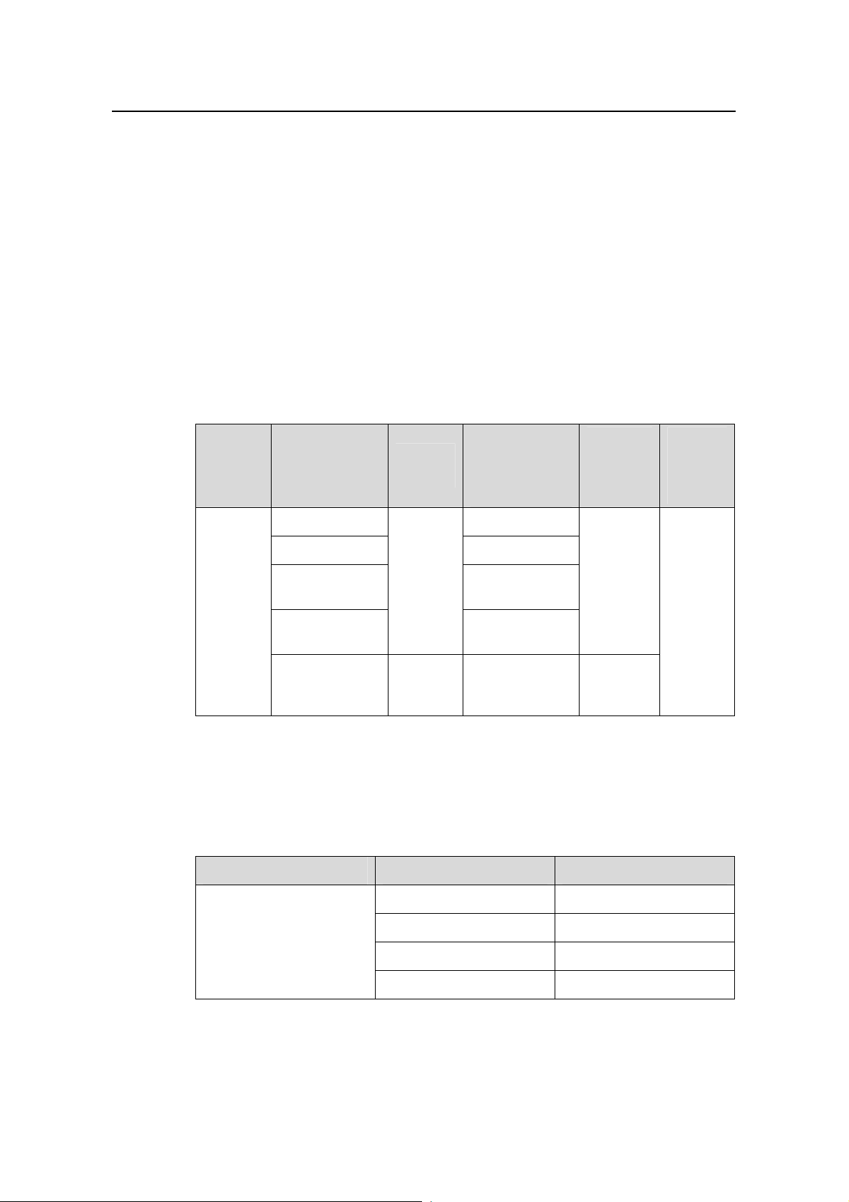
Table 1-1 H3C S5500-SI Series Ethernet switches
Number of
Name Model
S5500-28C-SI 24
S5500-52C-SI 48
H3C
S5500-SI
Series
Ethernet
switches
Each SFP port and the corresponding 10/100/1000BASE-T Ethernet port form a
Combo port. For each Combo port, either the SFP port or the corresponding
10/100/1000BASE-T Ethernet port can be used at a time. Refer to
Table 1-2 Combo port mapping relationship
S5500-28C-PW
R-SI
S5500-52C-PW
R-SI
S5500-20TP-SI AC input 8
Power
supply
AC input
or RPS
DC input
10/100/1000
Mbps
electrical ports
24
48
Number
of gigabit
uplink
ports
Four
Gigabit
SFP
Combo
ports
Twelve
Gigabit
SFP ports
Table 1-2.
Number
of
Console
ports
1
Model Combo port Corresponding port
S5500-28C-SI
S5500-28C-PWR-SI
25 22
26 24
27 21
28 23
1-1
Page 8

Installation Manual
H3C S5500-SI Complete Series Ethernet Switches Chapter 1 Product Overview
Model Combo port Corresponding port
49 46
S5500-52C-SI
S5500-52C-PWR-SI
50 48
51 45
52 47
Note:
A Gigabit Combo port and its corresponding 10/100/1000BASE-T autosensing
Ethernet port cannot be used together at the same time. For details, refer to the Port
Correlation Configuration part of the H3C S5500-SI Series Ethernet Switches
Operation Manual.
S5500-SI series have abundant service features. They provide the IPv6 forwarding
function and 10GE uplink interfaces, and support H3C-specific cluster management,
which simplifies your network management. S5500-SI series are designed as
convergence and access devices for enterprise networks and metropolitan area
networks (MANs), and can also be used for connecting server group s in d ata centers.
The feature-rich S5500-SI series switches support the following services:
z Broadband Internet access
z Access of MAN and enterprise network users
z Multimedia services, such as VoD
z Delay-sensitive voice services, such as VoIP
z Multicast audio and video services
S5500-SI series feature the following advantages:
z Providing full-Gigabit access ports
z Providing 10GE ports (except for the S5500-20TP-SI switch)
z Supporting IPv4/IPv6 dual-stack and hardware forwarding
z Supporting jumbo frames
z Supporting port security
z Supporting link aggregation control protocol (LACP)
z Supporting 4K VLANs
z Supporting QACL
z Supporting port-based/flow-based mirroring
1-2
Page 9
Installation Manual
H3C S5500-SI Complete Series Ethernet Switches Chapter 1 Product Overview
1.2 Introduction to S5500-SI Series Ethernet Switches
1.2.1 S5500-28C-SI Ethernet Switch
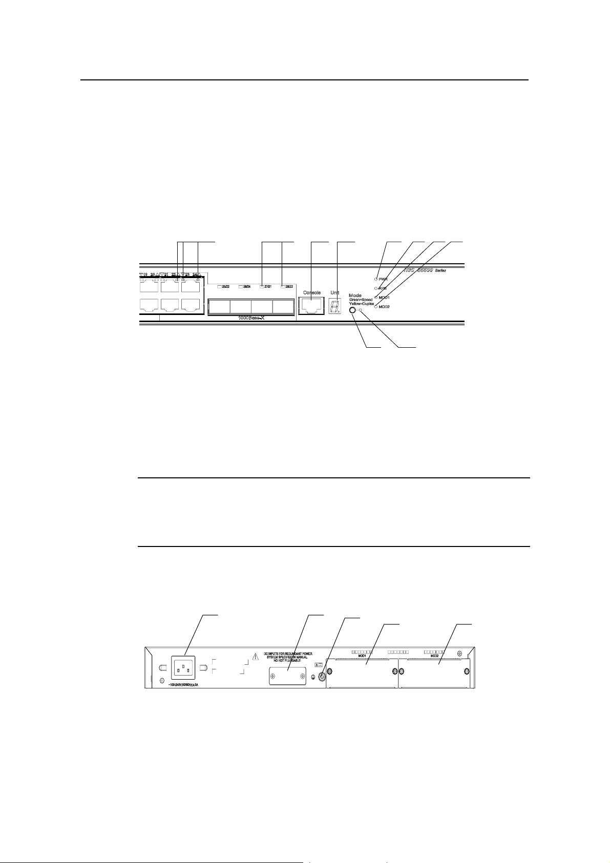
I. Front Panel
The S5500-28C-SI Ethernet switch provides 24 × 10/100/1000BA SE-T Ethernet ports,
four Gigabit SFP Combo ports and one Console port on the front panel.
shows the front panel appearance of the S5500-28C-SI Ethernet switch.
(2) (3) (4) (5) (6) (7) (8)
(1)
(1)
(1): 10/100/1000 BASE-T autosensing Ethernet port status LED
(2): Gigabit SFP Combo port status LED
(3): Console port (4): 7-segment digitron display
(5): Power LED (6): DC power LED
(7): LED for extended slot 1 (8): LED for extended slot 2
(9): Mode LED (10): Mode switching button
(2) (3) (4) (5) (6) (7) (8)
(9)
(10)
(10)
(9)
Figure 1-1
Figure 1-1 Front panel of the S5500-28C-SI Ethernet switch
Note:
For details about LEDs on the front panel, refer to section 1.3.1 “LEDs of
S5500-28C-SI/S5500-52C-SI Switch”.
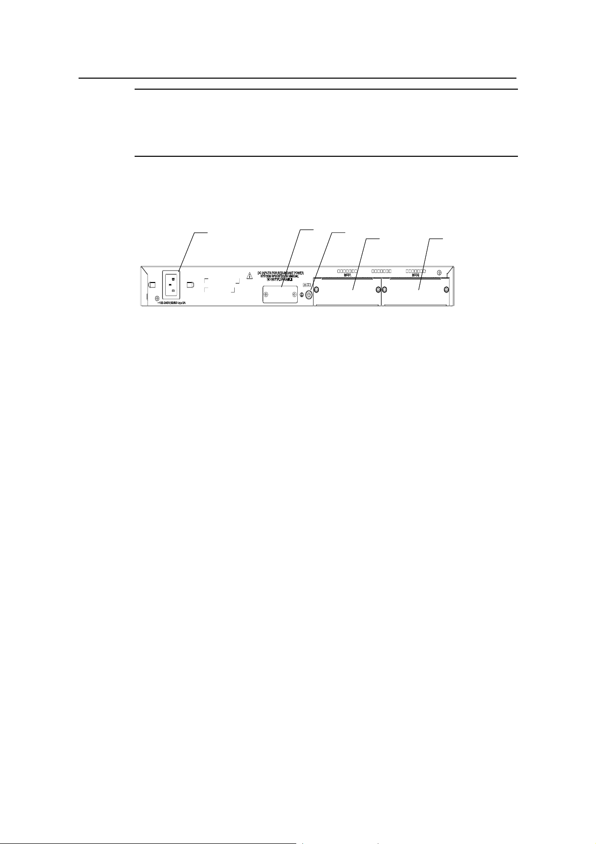
II. Rear Panel
(1) (2)
(1) (2)
(3)
(3)
(4)
(4)
(5)
(5)
(1): AC power input (2): DC power input
(3): Grounding screw (4): Extended slot 1
(5): Extended slot 2
Figure 1-2 Rear panel of the S5500-28C-SI Ethernet switch
1-3
Page 10
Installation Manual
H3C S5500-SI Complete Series Ethernet Switches Chapter 1 Product Overview
III. Power Supply System
The S5500-28C-SI Ethernet switch supports both AC input and RPS 12 V input. The
AC input and DC input can be used together to serve as backup for each other. In
addition, either of them can be used alone. You can use only the RPS power supply
recommended by H3C for DC input.
AC input:
Rated voltage range: 100 VAC to 240 VAC, 50 Hz or 60 Hz
Input voltage range: 90 VAC to 264 VAC, 50 Hz or 60 Hz
RPS (DC) input:
Rated voltage range: 10.8 VDC to 13.2 VDC
IV. Cooling System
The S5500-28C-SI Ethernet switch provides four fans for heat dissipation.
1.2.2 S5500-52C-SI Ethernet Switch
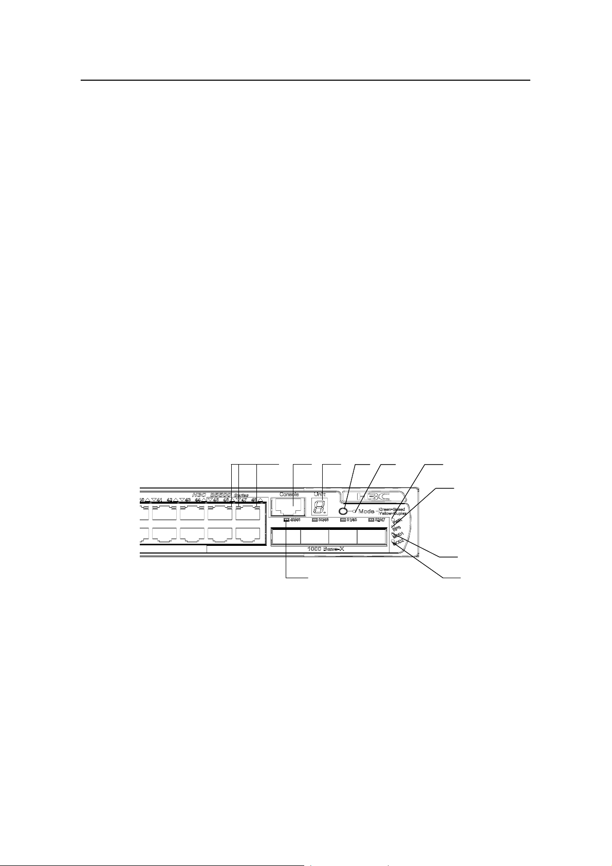
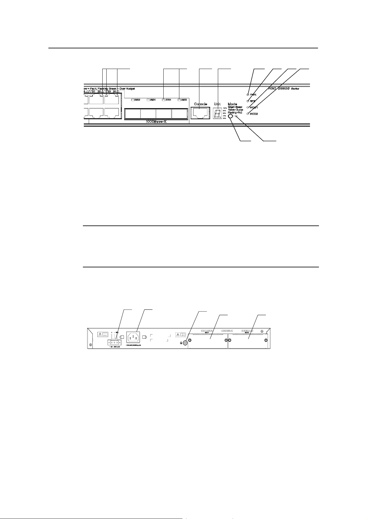
I. Front Panel
The S5500-52C-SI Ethernet switch provides 48 × 10/100/1000BA SE-T Ethernet ports,
four Gigabit SFP Combo ports and one Console port on the front panel.
Figure 1-3
shows the front panel appearance of the S5500-52C-SI Ethernet switch.
(1) (2)
(1) (2)
(10)
(10)
(3) (6)
(3) (6)
(4) (5)
(4) (5)
(7)
(7)
(8)
(8)
(9)
(9)
(1): 10/100/1000 BASE-T autosensing Ethernet port status LEDs
(2): Console port (3): 7-segment digitron display
(4): Mode switching button (5): Mode LED
(6): Power LED (7): DC Power LED
(8): LED for extended slot 1 (9): LED for extended slot 2
(10): Gigabit SFP Combo port status LED
Figure 1-3 Front panel of the S5500-52C-SI Ethernet switch
1-4
Page 11
Installation Manual
H3C S5500-SI Complete Series Ethernet Switches Chapter 1 Product Overview
Note:
For details about LEDs on the front panel, refer to section 1.3.1 “LEDs of
S5500-28C-SI/S5500-52C-SI Switch”.
II. Rear Panel
(1)
(1)
(2)
(3)
(3)
(4)
(4)
(5)
(5)
(2)
(1): AC power input (2): DC power input
(3): Grounding screw (4): Extended slot 1
(5): Extended slot 2
Figure 1-4 Rear panel of the S5500-52C-SI Ethernet switch
III. Power Supply System
The S5500-52C-SI Ethernet switch supports both AC input and RPS 12 V input. The
AC input and DC input can be used together to serve as backup for each other. In
addition, either of them can be used alone. You can use only the RPS power supply
recommended by H3C for DC input.
AC power input:
Rated voltage range: 100 VAC to 240 VAC, 50 Hz or 60 Hz
Input voltage range: 90 VAC to 264 VAC, 50 Hz or 60 Hz
RPS (DC) input:
Rated voltage range: 10.8 VDC to 13.2 VDC
IV. Cooling System
The S5500-52C-SI Ethernet switch provides four fans for heat dissipation.
1.2.3 S5500-28C-PWR-SI Ethernet Switch
I. Front Panel
The S5500-28C-PWR-SI Ethernet switch provides 24 × 10/100/1000Base-T Ethernet
ports, four Gigabit SFP Combo ports and one Console port on the front panel.
Figure
1-5 shows the front panel appearance of the S5500-28C-PWR-SI Ethernet switch.
1-5
Page 12
Installation Manual
H3C S5500-SI Complete Series Ethernet Switches Chapter 1 Product Overview
(2) (3) (4) (5) (6) (7) (8)
(2) (3) (4) (5) (6) (7) (8)
(2) (3) (4) (5) (6) (7) (8)
(1)
(1)
(1)
(1)
(2) (3) (4) (5) (6) (7) (8)
(9)
(9)
(9)
(10)
(10)
(10)
(10)
(9)
(1): 10/100/1000 BASE-T autosensing Ethernet port status LEDs
(2): Gigabit SFP Combo port status LED
(3): Console port (4): 7-segment digitron display
(5): Power LED (6): DC Power LED
(7): LED for extended slot 1 (8): LED for extended slot 2
(9): Mode LED (10): Mode switching button
Figure 1-5 Front panel of the S5500-28C-PWR-SI Ethernet switch
Note:
For details about LEDs on the front panel, refer to section 1.3.2 “LEDs of
S5500-28C-PWR-SI/S5500-52C-PWR-SI Switch”.
II. Rear Panel
(1) (2)
(1) (2)
(3)
(3)
(4)
(4)
(5)
(5)
(1): DC power input (2): AC power input
(3): Grounding screw (4): Extended slot 1
(5): Extended slot 2
Figure 1-6 Rear panel of the S5500-28C-PWR-SI Ethernet switch
III. Power Supply System
The S5500-28C-PWR-SI Ethernet switch supports both AC input and DC input. The AC
input and DC input can be used together to serve as backup for each other . In addition,
either of them can be used alone.
AC power input:
Rated voltage range: 100 VAC to 240 VAC, 50 Hz or 60 Hz
1-6
Page 13
Installation Manual
H3C S5500-SI Complete Series Ethernet Switches Chapter 1 Product Overview
Input voltage range: 90 VAC to 264 VAC, 50 Hz or 60 Hz
The S5500-28C-PWR-SI Ethernet switch supports only the external PoE power supply
recommended by H3C as the DC power. –48 VDC power cannot be used directly.
Otherwise, the device may be destroyed.
DC input:
Rated voltage range: –52 VDC to –55 VDC
IV. Cooling System
The S5500-28C-PWR-SI Ethernet switch provides six fans for heat dissipation.
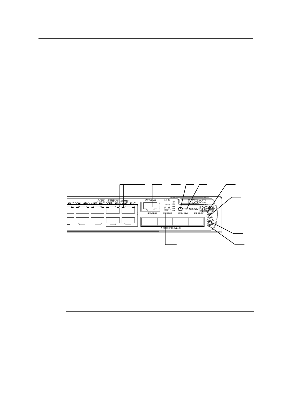
1.2.4 S5500-52C-PWR-SI Ethernet Switches
I. Front Panel
The S5500-52C-PWR-SI Ethernet switch provides 48 × 10/100/1000Base-T Ethernet
ports, four Gigabit SFP Combo ports and one Console port on the front panel.
1-7 shows the front panel appearance of the S5500-52C-PWR-SI Ethernet switch.
Figure
(1) (2)
(1): 10/100/1000 BASE-T autosensing Ethernet port status LEDs
(2): Console port (3): 7-segment digitron display
(4): Mode switching button (5): Mode LED
(6): Power LED (7): DC Power LED
(8): LED for extended slot 1 (9): LED for extended slot 2
(10): Gigabit SFP Combo port status LED
(3) (6)
(4) (5) (1) (2)
(3) (6)
(4) (5) (1) (2)
(3) (6)
(4) (5) (1) (2)
(3) (6)
(4) (5)
(10 )
(10 )
(10 )
(10 )
Figure 1-7 Front panel of the S5500-52C-PWR-SI Ethernet switch
Note:
(7)
(7)
(7)
(7)
(8 )
(8 )
(8 )
(8 )
(9 )
(9 )
(9 )
(9 )
For details about LEDs on the front panel, refer to section 1.3.2 “LEDs of
S5500-28C-PWR-SI/S5500-52C-PWR-SI Switch”.
1-7
Page 14

Installation Manual
H3C S5500-SI Complete Series Ethernet Switches Chapter 1 Product Overview
II. Rear Panel
(1) (2 )
(1) (2 )
(3)
(3)
(4)
(4)
(5)
(5)
(1): DC power input (2): AC power input
(3): Grounding screw (4): Extended slot 1
(5): Extended slot 2
Figure 1-8 Rear panel of the S5500-52C-PWR-SI Ethernet switch
III. Power Supply System
The S5500-52C-PWR-SI Ethernet switch supports both AC input and DC input. The AC
input and DC input can be used together to serve as backup for each other . In addition,
either of them can be used alone.
AC power input:
Rated voltage range: 100 VAC to 240 VAC, 50 Hz or 60 Hz
Input voltage range: 90 VAC to 264 VAC, 50 Hz or 60 Hz
The S5500-52C-PWR-SI Ethernet switch supports only the external PoE power supply
recommended by H3C as the DC power. –48 V DC power cannot be used directly.
Otherwise, the device may be destroyed.
DC input:
Rated voltage range: –52 VDC to –55 VDC
IV. Cooling System
The S5500-52C-PWR-SI Ethernet switch provides six fans for heat dissipation.
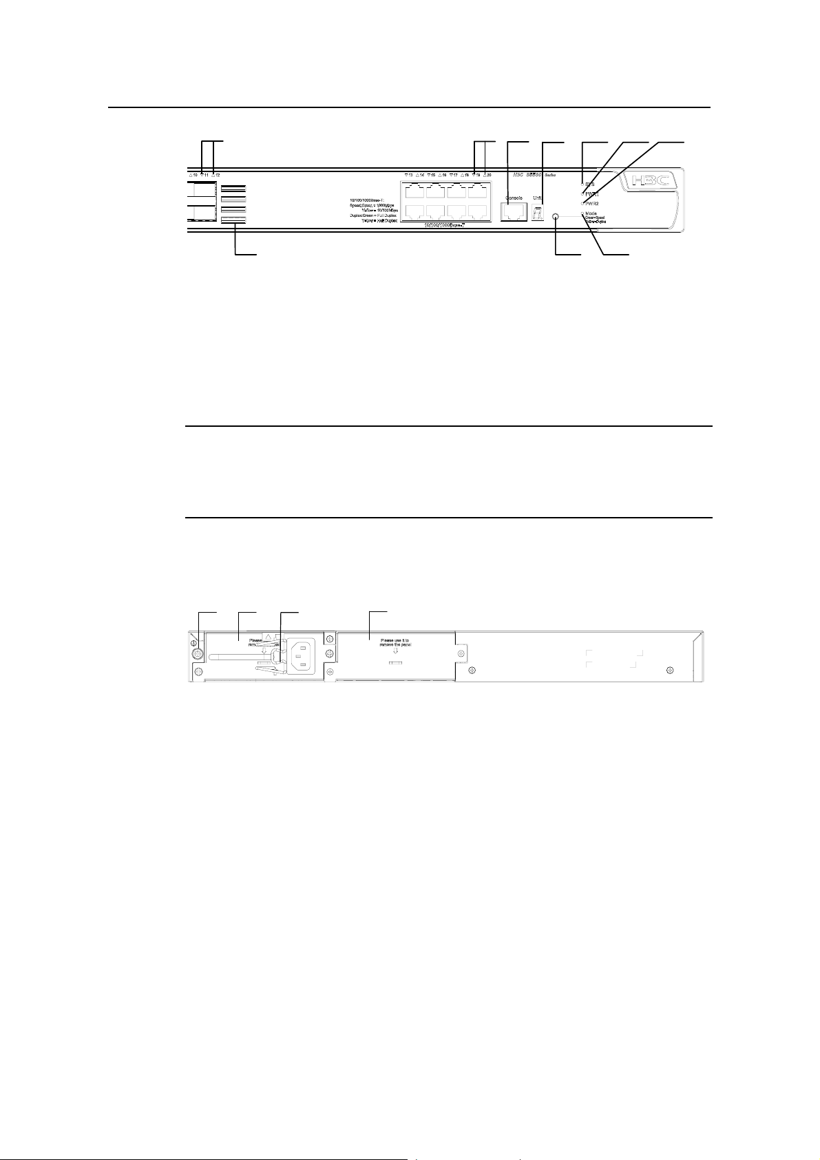
1.2.5 S5500-20TP-SI Ethernet Switch
I. Front panel
The S5500-20TP-SI Ethernet switch provides 12 Gigabit SFP ports, 8 ×
10/100/1000Base-T Ethernet ports, and one console port on the front panel.
shows the front panel appearance of the S5500-20TP-SI Ethernet switch.
Figure 1-9
1-8
Page 15
Installation Manual
H3C S5500-SI Complete Series Ethernet Switches Chapter 1 Product Overview
(1)
(2)
(3)
(4)
(5)
(6)
(7)
(10)
(9)
(8)
(1): 1000/100 Mbps SFP port LED (2): 10/100/1000 Base-T autosensing Ethernet port LED
(3): Console port (4): 7-segment digitron display
(5): System LED (6): LED for power slot 1
(7): LED for power slot 2 (8): Mode LED
(9): Mode switching button (10): Air intake vent
Figure 1-9 Front panel of the S5500-20TP-SI Ethernet switch
Note:
For details about LEDs on the front panel, refer to section 1.3.3 LEDs of
S5500-20TP-SI Switch.
II. Rear panel
(1)
(2)
(3)
(4)
(1): Grounding screw (2): Power slot 1
(3): Power cable bail latch (4): Power slot 2
Figure 1-10 Rear panel of the S5500-20TP-SI Ethernet switch
III. Power supply system
The S5500-20TP-SI Ethernet switch adopts AC input.
Rated voltage range: 100 VAC to 240 VAC, 50 Hz or 60 Hz
Input voltage range: 90 VAC to 264 VAC, 50 Hz or 60 Hz
IV. Cooling system
The S5500-20TP-SI Ethernet switch provides five fans (three for the system, and one
for each power module) for heat dissipation.
1-9
Page 16

Installation Manual
H3C S5500-SI Complete Series Ethernet Switches Chapter 1 Product Overview
1.3 Introduction to Front Panel LEDs
1.3.1 LEDs of S5500-28C-SI/S5500-52C-SI Switch
The S5500-28C-SI/S5500-52C-SI Ethernet switch provides LEDs on the front panel for
your convenience to monitor the switch.
You can use the mode button on the panel to switch the display mode (rate mode or
duplex mode) of LEDs.
Table 1-3 Description on the LEDs of the S5500-28C-SI/S5500-52C-SI Ethernet
switch
LED Mark Status Description
Table 1-3 describe s the meanings of the LEDs.
Mode LED Mode
Power LED PWR
DC power LED RPS
Rate
mode
Duplex
mode
Green, ON The switch starts normally.
Green, blinking (1
Hz)
Red, ON The system fails the POST.
Yellow, blinking (1
Hz)
OFF The switch is powered off.
Green, ON
Yellow, ON
OFF
Green,
ON
Yellow,
ON
The port status LEDs are
showing the port rates.
The port status LEDs are
showing the duplex mode of
the ports.
The system is performing
power-on self test (POST).
One or more ports fail the
POST.
Both AC and DC inputs are
normal.
The DC input is normal, but
the AC input is abnorm al or
disconnected.
The DC input is
disconnected.
Module LED
Module(
MOD)
Green, ON
Yellow, blinking
OFF The module is not installed.
1-10
The module is installed and
operates normally.
The module is not supported
or is in trouble.
Page 17
Installation Manual
H3C S5500-SI Complete Series Ethernet Switches Chapter 1 Product Overview
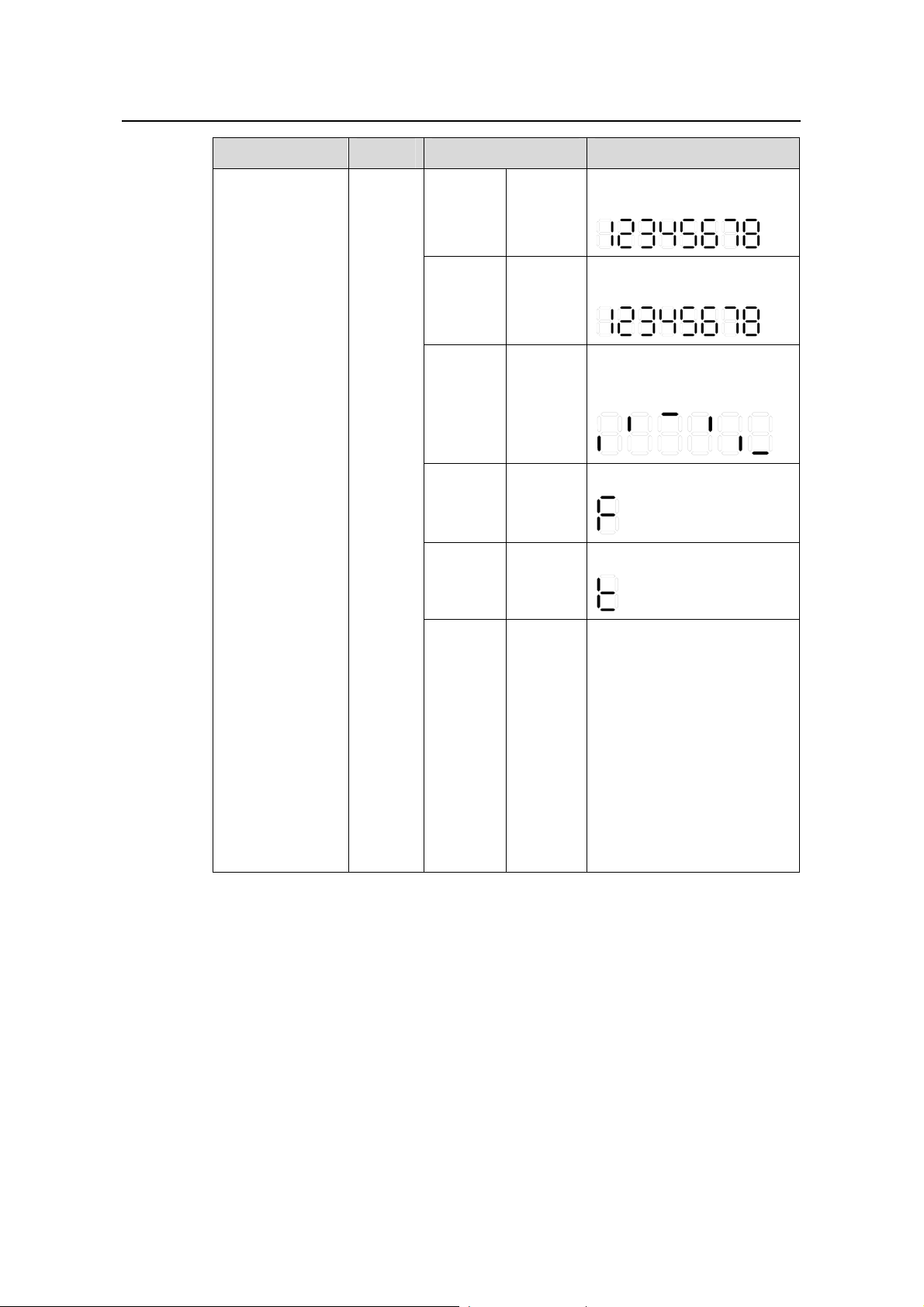
LED Mark Status Description
The POST ID of the
POST
running
Green,
blinking
in-process test is displayed.
The POST ID of the failed
POST
failed
Red,
blinking
test blinks.
A light bar rotates clockwise
around the display during
Loading
software
Green,
blinking
the loading procedure.
7-segment
digitron display
Unit
Fan
failure
Overtem
perature
alarm
Cluster
status
Red, ON
Red, ON
Green,
ON
An “F” is displayed.
A “t” is displayed.
A “C” is displ ayed if this is a
command switch.
An “S” is displayed if this is a
member switch.
A “c” is displayed if this is a
candidate switch.
A “1” is displayed when the
switch operates
independently.
(The default display is “c”,
that is, the device is
candidate switch by default.)
1-11
Page 18

Installation Manual
H3C S5500-SI Complete Series Ethernet Switches Chapter 1 Product Overview
LED Mark Status Description
The port works at the rate of
Green
1000 Mbps; the LED blinks
quickly when the port is
sending or receiving data.
The port works at the rate of
Rate
mode
Yellow
10/100 Mbps; the LED blinks
quickly when the port is
sending or receiving data.
Yellow,
blinking
POST fails on the port.
(3 Hz)
10/100/1000BAS
E-T Ethernet port
status LED
1000Base SFP
port status LED
—
—
Duplex
mode
This LED
is not
influence
d by the
mode
button
OFF The port is not connected.
The port works in full duplex
Green
mode; the LED blinks quickly
when the port is sending or
receiving data..
The port works in half duplex
Yellow
mode; the LED blinks quickly
when the port is sending or
receiving data..
Yellow,
blinking
POST fails on the port.
(3 Hz)
OFF The port is not connected.
The port works at the rate of
Green
1000 Mbps; the LED blinks
quickly when the port is
sending or receiving data.
Yellow,
blinking
POST fails on the port.
(3 Hz)
OFF The port is not connected.
1.3.2 LEDs of S5500-28C-PWR-SI/S5500-52C-PWR-SI Switch
The S5500-28C-PWR-SI/S5500-52C-PWR-SI Ethernet switch provides LEDs on the
front panel for your convenience to monitor the switch.
meanings of the LEDs. You can use the Mode button on the panel to swit ch the display
mode (rate mode, duplex mode, or PoE mode) of LEDs.
1-12
Table 1-4 describes the
Page 19

Installation Manual
H3C S5500-SI Complete Series Ethernet Switches Chapter 1 Product Overview
Table 1-4 Description on the LEDs of the S5500-28C-PWR-SI/S5500-52C-PWR-SI
Ethernet switch
LED Mark Status Description
Mode LED Mode
Power LED PWR
DC power LED RPS
Rate mode
Duplex
mode
PoE mode
Green,
ON
Yellow,
ON
Green,
blinking
(1 Hz)
The port status LEDs are
showing the port rate.
The port status LEDs are
showing the duplex mode of the
port.
The port status LEDs are
showing the PoE status of the
port.
Green, ON The switch starts normally.
Green, blinking (1
Hz)
The system is performing
power-on self test (POST).
Red, ON The POST fails the POST.
Yellow, blinking (1
Hz)
One or more ports fail the
POST.
OFF The switch is powered off.
Green, ON
Both AC and DC inputs are
normal.
The DC input is normal but the
Yellow, ON
AC input is abnormal or
disconnected.
Module LED
Module
(MOD)
OFF The DC input is disconnected.
Green, ON
Yellow, blinking
The module is installed and
operates normally.
The module is not supported or
is in trouble.
OFF The module is not installed.
1-13
Page 20
Installation Manual
H3C S5500-SI Complete Series Ethernet Switches Chapter 1 Product Overview
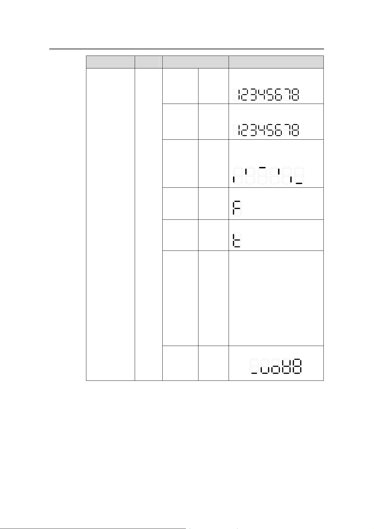
LED Mark Status Description
The POST ID of the in-process
POST
running
Green,
blinking
test is displayed.
The POST ID of the failed test
POST
failed
Red,
blinking
blinks.
A light bar rotates clockwise
around the display during the
Loading
software
Green,
blinking
loading procedure.
7-segment
digitron display
Unit
Fan
failure
Overtemp
erature
alarm
Cluster
status
PoE mode
Red,
ON
Red,
ON
Green,
ON
Green,
ON
An “F” is displayed.
A “t” is displayed.
A “C” is displ ayed if there is a
command switches.
An “S” is displayed if there is a
member switches.
A “c” is displayed if there is a
candidate switches.
A “1” is displayed when the
switch operates independently.
(The default display is “c”, that
is, the device is candidate
switch by default.)
Show the utilization of the
power
81 - 100%
61 - 80%
41 - 60%
21 - 40%
0 - 20%
1-14
Page 21

Installation Manual
H3C S5500-SI Complete Series Ethernet Switches Chapter 1 Product Overview
LED Mark Status Description
The port works at the rate of
Green
1000 Mbps; the LED blinks
quickly when the port is sending
or receiving data.
The port works at the rate of
Rate
mode
Yellow
10/100 Mbps; the LED blinks
quickly when the port is sending
or receiving data.
Yellow,
blinking
POST fails on the port.
(3 Hz)
OFF The port is not connected.
The port works in full duplex
Green
mode; the LED blinks quickly
when the port is sending or
receiving data.
The port works in half duplex
Duplex
mode
Yellow
mode; the LED blinks quickly
when the port is sending or
receiving data.
10/100/1000B
ASE-T
Ethernet port
status LED
—
PoE mode
Yellow,
blinking
POST fails on the port.
(3 Hz)
OFF The port is not connected.
Green,
ON
The port supplies power
normally
The required power of the
attached devices has exceeded
the maximum power that the
Green,
blinking
(1 Hz)
port can supply.
The total power that the switch
supplies has reached the
maximum power, so the port
does not supply power any
more.
The devices attached to the port
are not powered devices (PDs),
Yellow,
ON
so the port does not supply
power.
The PoE power fails, so the port
cannot supply power.
1-15
Yellow,
blinking
POST fails on the port
(3 Hz)
OFF The port does not supply power.
Page 22

Installation Manual
H3C S5500-SI Complete Series Ethernet Switches Chapter 1 Product Overview
LED Mark Status Description
The port works at the rate of
1000 Mbps; the LED blinks
quickly when the port is sending
or receiving data.
POST fails on the port.
1000Base SFP
port status
LED
—
This LED
is not
influenced
by the
mode
button
Green
Yellow,
blinking
(3 Hz)
OFF The port is not connected.
1.3.3 LEDs of S5500-20TP-SI Switch
The S5500-20TP-SI Ethernet switch provides LEDs on the front panel for your
convenience to monitor the switch.
can use the Mode button on the panel to switch the display mode (rate mode, or duplex
mode) of LEDs.
Table 1-5 describe s the meanings of the LEDs. You
Table 1-5 Description of LEDs on the front panel of the S5500-20TP-SI Ethernet
Switch
LED Mark Status Description
Speed
Solid
green
Rate of the port
Mode LED Mode
Solid
yellow
Duplex of the port
The switch is started
normally.
The system is running a
POST.
The system fails the POST
or a power failure occurs.
Some ports fail the POST or
a port failure occurs.
System power
LED
SYS
Duplex
Solid green
Flashing green (1 Hz)
Solid red
Flashing yellow (1
Hz)
OFF The power is disconnected.
A power module is installed
Solid green
in the power module slot and
the output is normal.
LED for power
module slot 1
PWR1
Solid yellow
OFF
1-16
A power module is installed
in the power module slot but
there is an output failure.
No power module is installed
in the power module slot or
no power is input.
Page 23
Installation Manual
H3C S5500-SI Complete Series Ethernet Switches Chapter 1 Product Overview
LED Mark Status Description
A power module is installed
Solid green
in the power module slot and
the output is normal.
LED for power
module slot 2
PWR2
Module LED MOD
A power module is installed
Solid yellow
in the power module slot but
there is an output failure.
No power module is installed
OFF
in the power module slot or
no power is input.
Solid green
The module is in position
and works normally.
The switch does not support
Flashing yellow
the module or a module
failure occurs.
OFF No module is installed.
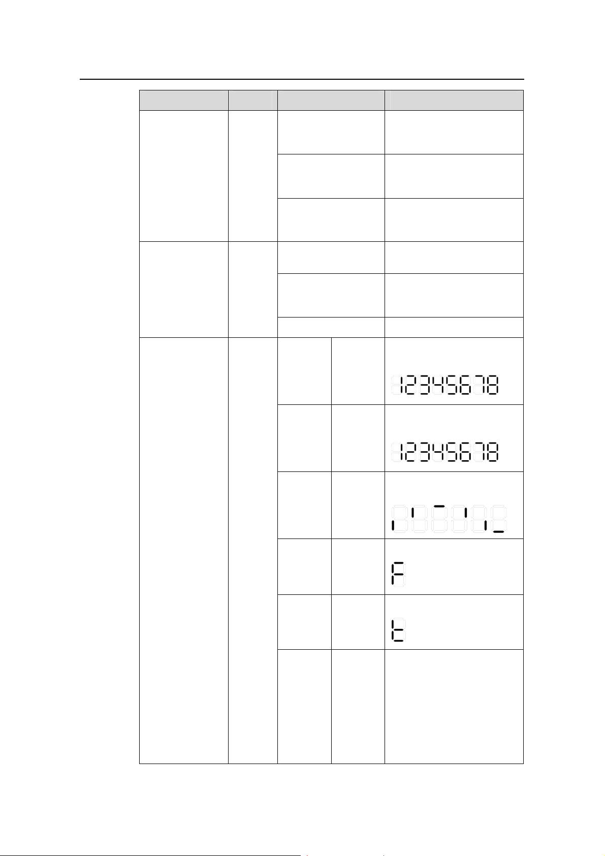
POST
running
The
power
LED
flashes
The LED displays the POST
test ID.
green.
POST
failed
The
power
LED
flashes
The LED flashes the POST
test ID of the failed test.
red.
7-segment digital
LED
Unit
Software
loading
Fan
failure
Over-tem
perature
alarm
Cluster
status
The
power
LED
flashes
green.
The
power
LED is
solid red.
The
power
LED is
solid red.
Solid
green
A bar rotates clockwise
around the LED.
The LED displays F.
The LED displays t.
For a command switch, the
LED displays C.
For a member switch, the
LED displays S.
For a candidate switch, the
LED displays c.
The LED displays 1 if there
is only one unit.
1-17
Page 24

Installation Manual
H3C S5500-SI Complete Series Ethernet Switches Chapter 1 Product Overview
LED Mark Status Description
A 1000 Mbps link is present.
Green
When data is being received
or sent, the LED flashes at a
high frequency.
A 10/100 Mbps link is
Speed
Yellow
present. When data is being
received or sent, the LED
flashes at a high frequency.
Flashing
yellow (3
The port fails the POST.
Hz)
Auto-sensing
10/100/1000Bas
e-T Ethernet port
status LED
SFP port status
LED (1000
Mbps)
—
—
Duplex
The
Mode
button
has no
effect on
the LED.
OFF No link is present.
The port operates in the full
duplex mode. When data is
Green
being received or sent, the
LED flashes at a high
frequency.
The port operates in the half
duplex mode. When data is
Yellow
being received or sent, the
LED flashes at a high
frequency.
Flashing
yellow (3
The port fails the POST.
Hz)
OFF No link is present.
A 1000 Mbps link is present.
Green
When data is being received
or sent, the LED flashes
every 30 milliseconds.
Flashing
yellow (3
The port fails the POST.
Hz)
OFF No link is present.
1-18
Page 25

Installation Manual
H3C S5500-SI Complete Series Ethernet Switches Chapter 1 Product Overview
1.4 System Specifications of the S5500-SI Series
Table 1-6 System specifications of the S5500-SI series
Item
Physical
dimensions
(H × W × D)
Weight
Management
port
GE ports on
the front
panel
Optional
interface
modules
S5500-28C-
SI
43.6 × 440 × 300 mm (1.72
× 17.3 × 11.8 in.)
4 kg (8.8 lb)
One console port
24 ×
10/100/1000
Mbps
electric ports
Four Gigabit
SFP Combo
ports
One-port 10 GE XFP interface module
Dual-port 10 GE XFP interface module
Short-haul dual-port 10GE CX4 interface module
S5500-52C
-SI
4.5 kg (9.9
lb)
48 ×
10/100/100
0 Mbps
electric
ports
Four
Gigabit
SFP
Combo
ports
S5500-28C-PWR
-SI
43.6 × 440 × 420 mm (1.72 × 17.3 ×
16.5 in.)
6 kg (13.2 lb) 6.5 kg (14.3 lb)
24 × 10/100/1000
Mbps electric
ports
Four Gigabit SFP
Combo ports
S5500-52C-PW
R-SI
48 ×
10/100/1000
Mbps electric
ports
Four Gigabit SFP
Combo ports
Input
volta
ge
Power
consumption
(full load)
AC
DC
Rated voltage range: 100 VAC to 240 VAC, 50 Hz or 60 Hz
Input voltage range: 90 VAC to 264 VAC, 50 Hz or 60 Hz
Rated voltage range:
10.8 VDC to 13.2 VDC
80 W
120 W
Rated voltage range:
–52 VDC to –55 VDC
455 W, with 85 W
of system power
consumption and
370 W of PoE
power
500 W when
RPS is not
connected, with
130 W of system
power
consumption and
370 W of PoE
power
870 W when
RPS is
connected, with
130 W of system
power
consumption and
740 W of PoE
power
1-19
Page 26
Installation Manual
H3C S5500-SI Complete Series Ethernet Switches Chapter 1 Product Overview
Item
S5500-28C-
SI
S5500-52C
-SI
S5500-28C-PWR
-SI
S5500-52C-PW
R-SI
Operating
temperature
0°C to 45°C (32°F to 113°F)
Relative
humidity
(noncondens
ing)
10% to 90%
Table 1-7 System specifications of the S5500-20TP-SI Ethernet switch
Item S5500-20TP-SI
Physical
dimensions
(H × W × D)
Weight
Management
port
GE ports on
the front
panel
43.6 × 440 × 360 mm (1.72 × 17.3 × 14.2 in.)
5.5 kg (12.1 lb)
One console port
12 Gigabit SFP Combo ports
8 × 10/100/1000 Mbps electric ports
Optional
interface
modules
Input
AC
volta
ge
DC
Power
consumption
(full load)
Operating
temperature
Relative
humidity
(noncondens
ing)
Interface modules not supported
Rated voltage range: 100 VAC to 240 VAC, 50 or 60 Hz
Input voltage range: 90 VAC to 264 VAC, 50 or 60 Hz
Not supported
65 W
0°C to 45°C (32°F to 113°F)
10% to 90%
1-20
Page 27

Installation Manual
H3C S5500-SI Complete Series Ethernet Switches Chapter 1 Product Overview
1.5 SFP Modules
The S5500-28C-SI, S5500-52C-SI, S5500-28C-PWR-SI, and S5500-52C-PWR-SI all
provide four 1000Base-X SFP ports to connect pluggable modules, while the ,
S5500-20TP-SI provides twelve 1000Base-X SFP ports. All SFP modules are hot
swappable and optional. Therefore, netwo rking is more flexible.
You can select required SFP modules from
Table 1-8.
Table 1-8 SFP modules that the S5500-SI series support
Item Type
SFP-GE-SX-MM850-A
SFP-GE-LX-SM1310-A
SFP module
SFP-GE-LH40-SM1310
SFP-GE-LH40-SM1550
SFP-GE-LH70-SM1550
Note:
z The S5500-SI series Ethernet switches support Gigabit SFP optical modules only.
z The types of SFP modules may vary over time. Consult H3C marketing personnel or
technical support personnel to obtain the latest information about SFP modules.
z For specifications of pluggable modules, refer to H3C Low End Series Ethernet
Switches Pluggable Modules Manual.
1.6 Optional Interface Modules
The S5500-SI series (excluding S5500-20TP-SI) provide two extended module slots on
the rear panel. You can select the following extended modules:
z One-port 10 GE XFP interface module
z Dual-port 10 GE XFP interface module
z Short-haul dual-port 10GE CX4 module
1-21
Page 28

Installation Manual
H3C S5500-SI Complete Series Ethernet Switches Chapter 1 Product Overview
1.6.1 One-port 10 GE XFP Interface Module
Figure 1-11 Front panel of one-port 10 GE XFP interface module
This module provides one 10 Gbps XFP optical interface. You can select the following
XFP optical modules as required.
Table 1-9 XFP optical modules
item Model
XFP-SX-MM850
XFP
XFP-LX-SM1310
XFP-LH40-SM1550-F1
Note:
z For specifications of XFP modules, refer to H3C Low End Series Ethernet Switches
Pluggable Module Manual.
z The types of XFP modules may vary over time. Consult H3C marketing personnel or
technical support personnel to obtain the latest information about XFP modules.
1.6.2 Dual-Port 10 GE XFP Interface Module
Figure 1-12 Front panel of dual-port 10 GE XFP interface module
This module provides two 10 Gbps XFP optical interface s. You can select the following
XFP optical modules as required, see section
1-22
Table 1-9
Page 29

Installation Manual
H3C S5500-SI Complete Series Ethernet Switches Chapter 1 Product Overview
1.6.3 Short-haul Dual-Port 10 GE CX4 Interface Module
Figure 1-13 Short-haul dual-port 10 GE CX4 interface module
This module provides two 10 Gbps electrical ports and supports CX4 electrical and
protocol standards. The maximum transmission distance is 3 m (9.8 f t). It uses standard
10GBase-CX4 cable no more than 3 m (9.8 ft).
Note:
You can use only dedicated CX4 cable to connect the port on the CX4 extension
module and another CX4 port. For dedicated CX4 cable, see section
1.6.4 Description of LEDs of Extension Modules
There is a LED for each port on the extended module panel. Table 1-10 describes the
LEDs.
Table 1-10 Description on LEDs of extension modules
LED Mark Status Description
Port LED of a
extended module
This LED is
not
—
affected by
the mode
button.
Green
ON
OFF
1.7 CX4 Cable
1.7 "CX4 Cable".
The port is normally
connected. The LED blinks
quickly when the port is
sending or receiving data.
The port is not connected.
You can use the CX4 cable to connect the CX4 port on the rear panel of an S5500-SI
series switch to another CX4 port.
1-23
Page 30

Installation Manual
H3C S5500-SI Complete Series Ethernet Switches Chapter 1 Product Overview
Figure 1-14 CX4 cable
The following three types of cables are available:
z 50 cm (19.7 in.): the connectors at both ends of the cable are bayonet connectors.
z 100 cm (39.4 in.): the connectors at both ends of the cable are bayonet
connectors.
z 300 cm (118.1 in.): the connectors at both ends of the cable are bayonet
connectors.
1-24
Page 31

Installation Manual
H3C S5500-SI Complete Series Ethernet Switches Chapter 2 Preparing for Installation
Chapter 2 Preparing for Installation
2.1 Safety Precautions
To avoid any device impairment and bodily injury caused by improper use, observe
these rules:
z Before cleaning the switch, unplug the power plug of the switch first. Do not clean
the switch with wet cloth or liquid.
z Do not place the switch near water or in a damp environment. Prevent water or
moisture from entering the switch chassis.
z Do not place the switch on an unstable case or desk. The switch might be
damaged severely in case of a fall.
z Ensure proper ventilation of the equipment room and keep the ventilation vents of
the switch free of obstruction.
z Make sure that the operating voltage is the same as the voltage labeled on the
switch.
z Do not open the chassis while the switch is operating or when electrical hazards
are present to avoid electrical shocks.
z When replacing interface cards, wear ESD-preventive gloves to avoid damaging
the cards.
2.2 Installation Site
The S5500-SI series must be used indoors. You can mount your switch in a rack or on
a workbench, but make sure:
z Adequate clearance is reserved at the air inlet/exhaust vents for ventilation.
z The rack or workbench has a good ventilation system.
z The rack is sturdy enough to support the device and its accessories.
z The rack or workbench is well earthed.
To ensure normal operation and long service life of your switch, install it in an
environment that meets the requirements described in the following subsections.
2.2.1 Temperature/Humidity
You must maintain a proper temperature and humidity in the equipment room.
Long-term high humidity may lead to bad insulation, electricity leakage, mechanical
property changes, and metal corrosion. However, if the relative humidity is two low,
captive screws may become loose as the result of contraction of insulation washers
and static electricity may be produced in a dry environment to jeopardize the circuits on
the device. High temperature is the most undesirable condition, because it accel erates
2-1
Page 32

Installation Manual
H3C S5500-SI Complete Series Ethernet Switches Chapter 2 Preparing for Installation
aging of insulation materials and can thus significantly lower reliability and service life of
your switch.
For the temperature and humidity requirements of dif ferent models, refer to se ction
System Specifications of the S5500-SI Series”.
“
2.2.2 Cleanness
Dust is a hazard to the operating safety of your device. The dust accumulated on the
chassis can be adsorbed by static electricity and result in poor contact of metal
connectors or metal contact points. Espe cially when the indoo r relative humidity is low,
electrostatic adsorption is more likely to happen. This can not only shorten the service
life of your device but also cause communications failures. The following table lists the
dust concentration limit.
Table 2-1 Dust concentration limit in the equipment room
Dust
Note: The dust particle size ≥ 5 μm.
Besides dust, there are rigorous limits on the content of harmful substances in the air
that can accelerate the corrosion and aging of metals, such as chloride, acid, and
sulfide in the equipment room, and the equipment room must be protected against
ingression of harmful gases such as SO
see the following table.
Substance Unit Concentration limit
4
(no visible dust on the
Particles/m³
≤ 3 x 10
tabletop within three days)
, H2S, NH3, and Cl2. For specific requirements,
2
1.4
Table 2-2 Harmful gas limits in the equipment room
Gas Maximum concentration (mg/m3)
SO
2
H2S 0.006
NH3 0.05
Cl2 0.01
2.2.3 Electromagnetic Susceptibility
The operation of your switch can be affected by external interferences, such as
conducted emission by capacitance coupling, inductance coupling, electromagnetic
wave radiation, and common impedance (including the grounding system) coupling,
and leads (power cords, signaling cables and output wires). To eliminate the
interferences, pay attention to the following:
0.2
2-2
Page 33

Installation Manual
H3C S5500-SI Complete Series Ethernet Switches Chapter 2 Preparing for Installation
z As the AC power system is a TN system, use a single-phase three-wire power
socket with Protection Earth (PE) to effectively filter interference from the power
grid.
z Keep the device far from radio transmitting stations, radar stations, and
high-frequency devices.
z Use electromagnetic shielding when necessary, for example, use shielded
interface cables.
z Route interface cables only indoors to prevent signal ports from getting damaged
by overvoltage or overcurrent caused by lightning strikes.
2.2.4 Laser Safety
The S5500-SI series are Class 1 laser devices.
When the extended optical interface cards on the S5500-SI series are ope rating, do not
stare into the optical ports because the laser light emitted by the optical fiber may hurt
your retina.
Caution:
Staring into the laser beam produced by the fiber may hurt your eyes.
2.3 Installation Tools
z Flathead screwdriver
z Phillips screwdriver
z ESD-preventive wrist strap
Caution:
The installation tools are not shipped with the S5500-SI series.
2-3
Page 34

Installation Manual
H3C S5500-SI Complete Series Ethernet Switches Chapter 3 Installing the Switch
Chapter 3 Installing the Switch
Caution:
When you ask your sales agent to maintain the switch, you must ensure that the
dismantlement-preventive seal on a mounting screw of the H3C switch chassi s is intact.
If you want to open the chassis, you should contact the agent for permission. Otherwise,
you will bear any consequence resulted from your actions without permission.
3.1 Rack-Mounting the Switch
3.1.1 Cabinet Mounting
You can install a switch into a 19-inch standard cabinet in one of the following four
ways:
z Use front mounting ears
z Use front mounting ears and a tray
z Use front mounting ears and rear mounting ears
z Use front mounting ears and guide rails
The installation methods of a switch depend on the depth and width of the switch. For
the specific installation methods, see
Table 3-1 Installation methods for a switch with a width of 440 mm (17.3 in)
Method
Depth
300 mm (11.8 in) √ — √ √
420 mm (16.5 in) — √ √ √
Use front
mounting
ears
Table 3-1.
Use front and
rear mounting
ears
Use front
mounting
ears and a
tray
Use front
mounting
ears and
guide rails
3-1
Page 35

Installation Manual
H3C S5500-SI Complete Series Ethernet Switches Chapter 3 Installing the Switch
Note:
z When the depth of a switch is greater than 300 mm (11.8 in), the front mounting ears
only secure the switch rather than bear its weight.
z Guide rails purchased from H3C apply only to standard cabinets 1,000 mm (39.4 in)
deep. Use other supports to substitute for guide rails in the case of other cabinet
depths.
I. Introduction to mounting ear
Figure 3-1 shows the appearance of a front mounting ear.
(1) (2)
(1): Screw hole used to fix the mounting ear to the cabinet (Use one M6 screw)
(2): Screw hole used to fix the switch to the mounting ear
Figure 3-1 Appearance of a standard front mounting ear
Figure 3-2 shows the appearance of a rear mounting ear.
(1): Screw hole used to fix the mounting ear to the cabinet (Use one M6 screw)
Figure 3-2 Appearance of a rear mounting ear
3-2
Page 36

Installation Manual
H3C S5500-SI Complete Series Ethernet Switches Chapter 3 Installing the Switch
When you install S5500-SI Series Ethernet switches into 19-inch standard cabinets,
you should select front and rear mounting ears with a proper length according to the
physical dimensions of switches. For the selection of front and rear mounting ears, see
Table 3-2.
Table 3-2 Selection of mounting ear for S5500-SI Series Ethernet switches
Model
S5500-28C-SI
S5500-52C-SI
S5500-28C-PWRSI
S5500-52C-PWRSI
S5500-20TP-SI
Physical dimensions
(H × W × D)
43.6 × 440 × 300 mm
(1.72 × 17.3 × 11.8 in.)
43.6 × 440 × 300 mm
(1.72 × 17.3 × 11.8 in.)
43.6 × 440 × 420 mm
(1.72 × 17.3 × 16.5 in.)
43.6 × 440 × 420 mm
(1.72 × 17.3 × 16.5 in.)
43.6 × 440 × 360 mm
(1.72 × 17.3 × 14.2 in.)
II. Introduction to guide rail
Figure 3-3 shows the appearance of a guide rail.
Slotted hole 1 Cooling hole Slotted hole 2
Configuration
type of front
mounting ear
Configuratio
n type of rear
mounting ear
Standard —
Standard —
Standard Standard
Standard Standard
Standard Standard
Slotted hole 1: Used to fix the guide rail to the rear bracket. You can adjust the screw hole
position according to the position of the switch.
Cooling hole: Used for heat dissipation between switch and cabinet
Slotted hole 2: Used to fix the guide rail to the front bracket
Figure 3-3 Appearance of a guide rail
3-3
Page 37

Installation Manual
H3C S5500-SI Complete Series Ethernet Switches Chapter 3 Installing the Switch
Note:
Guide rails are optional parts. Check Table 3-1 to see whether you need to order them
or not.
III. Use front mounting ears to install a switch
Follow these steps to mount a switch into a 19-inch standard cabinet:
1) Wear an ESD-preventive wrist strap to check the grounding and stability of the
cabinet.
2) Take out the screws which are packed together with the front mounting ears, and
fix one end of mounting ears to the switch, as shown in
Figure 3-4.
Front panel
Figure 3-4 Fix front mounting ears (1)
3) Place the switch horizontally in a proper position, and fix the other end of mounting
ears to the front brackets with screws and captive nuts, as shown in
Figure 3-5.
3-4
Page 38

Installation Manual
H3C S5500-SI Complete Series Ethernet Switches Chapter 3 Installing the Switch
Fr ont square-holed brac k et
Fr ont square-holed brac k et
Fr ont mounting ear
Fr ont mounting ear
Fr ont panel
Fr ont panel
Front
Front
mount ing ear
mount ing ear
Figure 3-5 Fix front mounting ears (2)
IV. Use front mounting ears and a tray
Follow these steps to install a switch into a 19-inch standard cabinet:
1) Wear an ESD-preventive wrist strap to check the grounding and stability of the
cabinet.
2) Fix the delivered tray horizontally in a proper position.
3) Take out the screws which are packed together with the front mounting ears, and
fix one end of mounting ears to the switch, as shown in
Figure 3-4.
4) Place the switch on the tray horizontally, slide the tray into the cabinet, and fix the
other end of mounting ears to the front brackets with crews and captive nuts, as
shown in
Figure 3-5.
V. Use front and rear mounting ears
Follow these steps to install a switch into a 19-inch standard cabinet:
1) Wear an ESD-preventive wrist strap to check the grounding and stability of the
cabinet.
2) Take out the screws which are packed together with the front mounting ears, and
fix one end of mounting ears to the switch, as shown in
Figure 3-4.
3) Take out the load-bearing screws (packed together with the rear mounting ears)
and place them in a proper position on the sides of the switch, as sh own in
Figure
3-6.
3-5
Page 39

Installation Manual
H3C S5500-SI Complete Series Ethernet Switches Chapter 3 Installing the Switch
Three installation locations for screw 1 (select one according to the actual requirement)
Three installation locations for screw 1 (select one according to the actual requirement)
Screw 1
Screw 1
Screw 1
Screw 1
Front mounti ng ear
Front mounti ng ear
Screw 1: Load-bearing screw
Front pan el
Front pan el
Front
Front
mounting ear
mounting ear
Figure 3-6 Fix front mounting ears and load-bearing screws
Note:
There are three positions to mount a load-bearing screw on both sides of a switch. You
should select a proper position according to the actual requirements. The rear
mounting ears tightly contacted with the load-bearing screws can support the switch.
4) Select a position to install the switch and fix the rear mounting ears to the rear
brackets with screws and captive nuts, as shown in
Figure 3-7.
Figure 3-7 Fix rear mounting ears
Rear square-holed rack
3-6
Page 40

Installation Manual
H3C S5500-SI Complete Series Ethernet Switches Chapter 3 Installing the Switch
5) Hold the bottom of the switch with one hand and the front part of the switch with
the other hand, and push the switch into the cabinet gently, as shown in
Figure
3-8.
Rear mounting ear
Front square-holed bracket
Screw 2
Rear square-holed
bracket
Scre w 1
Front mounting ear Rear panel
Screw 1: Used to bear the weight
Screw 2: Used to fix rear mounting ears to rear brackets
Figure 3-8 Fix front and rear mounting ears
After the switch is pushed into the cabinet, ensure that the upper edge of rear mounting
ears is tightly contacted with the load-bearing screw, as shown in
Figure 3-9.
Rear square-
Rear panel
Screw 1: Load-bearing screw
holed bracket
Rear mounting ear
Figure 3-9 Effect diagram of front and rear mounting ear installation (1)
3-7
Screw 1
Page 41

Installation Manual
H3C S5500-SI Complete Series Ethernet Switches Chapter 3 Installing the Switch
6) Fix the other end of the front mounting ears to the front brackets with screws and
captive nuts and ensure that front and rear mounting ears have fixed the switch i n
the cabinet securely, as shown in
Screw 1
Rear
mounting ear
Figure 3-10.
Front panel
Front mounting ear
Front square-holed bracket
Screw 1: Load-bearing screw
Figure 3-10 Effect diagram of front and rear mounting ear installation (2)
VI. Use front mounting ears and guide rails
Follow these steps to install a switch into a 19-inch standard cabinet:
1) Wear an ESD-preventive wrist strap to check the grounding and stability of the
cabinet.
2) Take out the screws packed together with the front mounting ears and fix one end
of the front mounting ears to the switch, as shown in
Figure 3-4.
3) Install guide rails on the brackets on both sides of the cabinet with M5 self-tapping
screws.
Figure 3-11 is for reference only.
3-8
Page 42

Installation Manual
H3C S5500-SI Complete Series Ethernet Switches Chapter 3 Installing the Switch
Figure 3-11 Install guide rails
4) Hold the two sides of the switch and slide it gently along the guide rails into the
cabinet until it is located in a proper position, as shown in
Figure 3-12. Ensure that
the bottom side of the guide rails and the switch are in close contact.
Front panel
Figure 3-12 Install front mounting ears and guide rails
5) Fix the other end of front mounting ears to the front brackets of the cabinet with M6
screws and captive nuts and ensure that the front mounting ears and guide rails
have fixed the switch in the cabinet securely, as shown in
3-9
Figure 3-13.
Page 43

Installation Manual
H3C S5500-SI Complete Series Ethernet Switches Chapter 3 Installing the Switch
Rear panel
Guide
rail
Figure 3-13 Effect diagram of front mounting ear and guide rail installation
Note:
Ensure a clearance of 1U (44.45 mm, namely, 1.75 inches) between devices for the
purpose of heat dissipation.
3.1.2 Mounting the Switch on a Workbench
In many cases, standard 19-inch racks are not available. Therefore, switche s are often
placed on clean workbenches. To place your switch on a workbench, you simply need
to:
z Make sure that the workbench is clean, flat, and sturdy.
z Makes sure that the environment is well ventilated and allow 10 cm (3.9 in.) of
space around the chassis for heat dissipation.
z Do not place heavy objects on your switch.
z In the case of stack application, the vertical distance between two switches must
be at least 1.5 cm (0.59 in).
3-10
Page 44

Installation Manual
H3C S5500-SI Complete Series Ethernet Switches Chapter 3 Installing the Switch
3.2 Connecting the Power Cords and the Ground Wire
3.2.1 Connecting the AC Power Cord
I. AC power source socket (recommended)
You are recommended to use a single-phase three-wire power socket with a neutral
contact or a general purpose PC power socket, making sure that the neutral point is
well connected to building ground. Normally, the neutral point of the power source in a
building has been buried in the ground during the building construction and cable
routing stage. Still, you must make sure that the power source of the build is reliably
grounded.
Neutral point
Neutral point
Live line
Zero line
Zero line
Figure 3-14 Power socket (recommended)
Live line
II. Connecting the AC Power Cord
Step 1: Connect on e end of the ch assis ground wire to the grounding scre w on the rear
of the chassis and the other end to the ground as near as possible.
Step 2: Connect one end of the power cord to the power input on the rear panel of the
chassis, and plug the other end to the AC power input of the power source.
Step 3: Inst all the powe r cord ret ainer for the AC power cord. Insert the two ends of the
power cord retainer into the slots at both sides of the AC power input, and then set the
power cord into the notch of the power cord retainer.
(1): Rear panel of the switch (2): Power cord retainer slots
(3): AC power cord retainer (4): AC power cord
Figure 3-15 Installing AC power cord retainer
3-11
Page 45

Installation Manual
H3C S5500-SI Complete Series Ethernet Switches Chapter 3 Installing the Switch
Note:
The AC power cord retainer can prevent the AC power cord from accidentally falling off.
Step 4: Check whether the PWR LED o n the front p anel of the swit ch is ON. If the LED
is ON, it shows the power cord is properly connected.
Caution:
Make sure that the ground wire has been properly connected before powering on the
switch.
3.2.2 Connecting the DC Power Cord
I. Connecting the DC Power cord of the S5500-28C-SI and S5500-52C-SI
switches
The S5500-28C-SI and S5500-52C-SI switches use 12V-RPS DC power.
Pin Number Designation Pin Number Designation
1 GND 8 GND
2 -50V 9 -50V
3 12V 10 RPS_pres
4 12V 11 -50Vrtn
5 12V 12 -50Vrtn
6 12V 13 Control Pin
7 GND 14 GND
Figure 3-16 Appearance of the socket for 12V-RPS DC power of the switch
Step 1: Connect on e end of the ch assis ground wire to the grounding scre w on the rear
panel of the chassis and the other end to the ground as near as possible.
Step 2: Connect the cable to the plug of the 12V-RPS DC power.
z As shown in Figure 3-17, loosen the fastening screws and remove the air filter
from the 12V-RPS DC power socket. (In the case of no 12V-RPS DC power supply,
re-install the air filter.)
3-12
Page 46

Installation Manual
H3C S5500-SI Complete Series Ethernet Switches Chapter 3 Installing the Switch
(2)(1)
(1): Air filter (2): Fastening screw
Figure 3-17 12V-RPS power socket for the Ethernet switch
z Connect one connector (in A direction) of the 12V-RPS DC power cable (Figure
3-18 shows a recommended 12V-RPS DC power cable) to the RPS DC power
socket of the switch, and the other connector (in B direction) to the corresponding
12 V power output socket of the RPS power module.
D irection A D irection B
1
7
14
8
14
7
8
1
Figure 3-18 12V-RPS DC power cable
z Connect one end of the delivered AC power cable to the power socket of the RPS
power module and the other end to the socket of an external AC power supply.
Step 3: Check whethe r the PWR LE D on the front p a nel of the swit ch i s ON. If yes, the
power is properly connected.
Caution:
z Make sure that the ground wire has been properly connected before powering on
the switch.
z You can use only the 12V-RPS DC power cord recommended by H3C.
II. Connecting the DC Power Cord of the S5500-28C-PWR-SI and
S5500-52C-PWR-SI switches
The S5500-28C-PWR-SI and S5500-52C-PWR-SI switches use RPS DC power,
whose rated input voltage is in the range of -52V to -55V.
3-13
Page 47

Installation Manual
H3C S5500-SI Complete Series Ethernet Switches Chapter 3 Installing the Switch
+-NULL+-NULL
+: working ground -: -52 VDC to -55 VDC NULL: Reserved
Figure 3-19 Appearance of the RPS DC power socket of the switch
1) Connect one end of the grounding wire (delivered with the switch) to the grounding
screw and the other end to the ground nearby.
2) Insert the connector into the DC socket directly. Use the flat-blade screwdriver to
fix the connector with screw 1 and screw 2 (delivered with the switch), as shown in
Figure 3-20.
Note:
The position of the power socket on a device varies with devices. Refer to the real
device for the power socket position.
Figure 3-20 Fix the RPS DC power connector to t h e chassis
3) Check whether the PWR LED on the front panel of the switch is ON. If the LED is
ON, it shows the power cord is properly connected.
3-14
Page 48

Installation Manual
H3C S5500-SI Complete Series Ethernet Switches Chapter 3 Installing the Switch
Caution:
z Make sure that the ground wire has been properly connected before powering on
the switch.
z The length of the DC power cord must be less than 3 m (9.8 ft).
3.2.3 Connecting the Ground Wire
Caution:
Correctly connecting the switch ground wire is crucial to the lightning protection and
electromagnetic susceptibility (EMS) of your switch.
The power input end of the switch is connected with a noise filter , whose central gro und
is directly connected to the chassis, forming the chassis ground (commonly known as
PGND). This chassis ground must be securely connected to the earth ground so that
the faradism and leakage electricity can be safely released to the ground, enhancing
the EMS capability of the switch. Ground your switch as follows:
z When a grounding strip is available at the installation site, attach one end of the
yellow/green ground wire of the switch to the grounding screw on the grounding
strip and fasten the captive nut. Note that the fire main and lightning rod of a
building are not suitable for grounding the switch. The ground wire of the switch
should be connected to the grounding device for the equipment room.
(2)
(2)
(3)
(3)
(4)
(1)
(1)
(4)
(1): Power input on the switch (2): Grounding screw on the switch
(3): Protection ground wire (4): Grounding strip
Figure 3-21 Ground the switch through a grounding strip
z When there is no grounding strip but earth is available near the installation location
and allows a grounding body to be buried, hammer an angle iron/steel pipe l onger
3-15
Page 49

Installation Manual
H3C S5500-SI Complete Series Ethernet Switches Chapter 3 Installing the Switch
than 0.5 m (1.64 ft) into the earth. Weld the yellow-green ground wire of the swit ch
onto the angle iron/steel pipe, and treat the joint for corrosion protection.
(2 )
(2 )
(3 )
(3 )
(1 )
(1 )
(1 )
(1 )
(5 )
(5 )
(4 )
(4 )
(1): Power input on the switch (2): Grounding screw on the switch
(3): Protection ground wire (4): Ground
(5): Angle steel
Figure 3-22 Ground the switch by burying the grounding body into the earth
z For an AC-powered switch, if neither of the above-mentioned two conditions is
available, ground the switch through PE wire of the AC power supply. In this case,
make sure this PE wire is well connected to the ground at the power distribution
room or AC transformer side.
(1)
(3)
(2)
(2)
(6)
(4)
(5)
(1): AC power input (2): Grounding screw (3): Power transformer
(4): PE ground wire (5): Three-wire AC power input cable (6): Ethernet switch
Figure 3-23 Ground through an AC PE wire
z For a -48V-DC-powered switch, if none of the first two conditions mentioned above
is available, ground it through the return wire (RTN) of the DC power supply. In this
case, make sure this RTN wire is well connected to the ground at the DC output of
the DC power cabinet.
3-16
Page 50

Installation Manual
H3C S5500-SI Complete Series Ethernet Switches Chapter 3 Installing the Switch
(1)
(1)
(1)
(1)
(11)
(11)
(11)
(11)
(2)
(2)
(4)
(4)
(6)
(6)
(3)
(3)
(5)
(5)
(7)
(7)
(8 )
(8 )(8 )
(8 )
(8 )()
(8 )
(8 )(8 )
(8 )
(8 )()
(9)
(9)(9)
(9)
(9)()
(9)
(9)(9)
(9)
(9)()
(10)
(10)
(1): AC/DC power cabinet (2): -48V strip (3): -48V
(4): RTN strip (5): RTN (6): PGND strip
(7): Grounding (8): Protection ground wire (9): Grounding screw
(10): Ethernet switch (11): DC power input
Figure 3-24 Ground through the PGND of a power cabinet
3.3 Connecting Optical Fiber
Caution:
z After a switch starts, the optical port may emit invisible radial when there is no
optical connector connected to it and the protective cap is removed from it.
Therefore, do not stare into the optical interface.
z Be sure to cover the protective cap within 10 seconds if an optical connector is not in
use to keep the optical connector clean.
z Be sure to cover the protective cap if an optical port has no optical connector
attached.
z Place the protective caps in a safe place when an optical port has fiber connected to
prepare for the cases the fiber is pulled out.
3.4 Connecting Console Cable
3.4.1 Console Cable
A Console cable is an 8-core cabl e. One end of the cable is a crimp ed RJ-45 connector
for the connection to the Console port of the switch, and the other end is a DB-9 female
connector for the connection to the serial port on the Console terminal, as shown
below.
3-17
Page 51

Installation Manual
H3C S5500-SI Complete Series Ethernet Switches Chapter 3 Installing the Switch
Figure 3-25 Console cable
Table 3-3 Console cable pinouts
RJ-45 Signal Direction DB-9 (MODEM)
1 RTS → 7 8
2 DTR → 4 6
3 TXD → 3 2
4 CD ← 1 5
5 GND — 5 5
6 RXD ← 2 3
7 DSR ← 6 4
8 CTS ← 8 7
3.4.2 Connecting Console Cable
When you want to use the terminal to configure the switch, follow these steps to
connect a terminal device to your switch using Console cables:
Step 1: Plug the DB-9 female connector of the Consol e cable to the serial port of the PC
or terminal where the switch is to be configured.
DB-9
(CONSOLE)
Step 2: Connect the RJ-45 connector of the Console cable to the Console port of the
switch.
Caution:
Pay attention to the mark on the Console port and be sure to plug the connector to the
right port.
3-18
Page 52

Installation Manual
H3C S5500-SI Complete Series Ethernet Switches Chapter 3 Installing the Switch
Note:
When connecting a PC to a powered-on switch, you are recommended to connect the
DB-9 connector of the Console cable to the PC before connecting the RJ-45 conn ector
to the switch. When disconnecting a PC from a powered-on switch, you are
recommended to disconnect the DB-9 connector of the Console cable from the PC
after disconnecting the RJ-45 connector from the switch.
3.5 Installing and Removing Optional Interface Modules
The S5500-SI series (excluding S5500-20TP-SI) provide two extended module slots on
the rear panel. You can select the following extended modules:
z One-port 10 GE XFP interface module
z Dual-port 10 GE XFP interface module
z Short-haul dual-port 10 GE CX4 interface modules
3.5.1 10 GE XFP Interface Module
I. Appearance and front panel of a one-port 10 GE XFP interface module
Figure 3-26 Appearance of a one-port 10 GE XFP interface module
Figure 3-27 Front panel of a one-port 10 GE XFP interface module
3-19
Page 53

Installation Manual
H3C S5500-SI Complete Series Ethernet Switches Chapter 3 Installing the Switch
II. Appearance and front panel of a dual-port 10 GE XFP interface module
Figure 3-28 Appearance of a dual-port 10 GE XFP interface module
Figure 3-29 Front panel of a dual-port 10 GE XFP interface module
III. Installation procedure
Step 1: Put on an ESD-preventive wrist strap and verify the ESD-preventive wrist strap
properly grounded. Then take out the XFP interface module from the package.
Step 2: Loosen the mounting screws of the filler panel on the read panel of the switch
with a screwdriver and remove the filler panel.
Step 3: Hold the fastening screws on the front panel of the XFP interface module, and
gently push the XFP interface module in alon g the slot guide rail until the XFP interface
module is in close contact with the switch.
3-20
Page 54

Installation Manual
H3C S5500-SI Complete Series Ethernet Switches Chapter 3 Installing the Switch
(1): Switch (2): Optional module slot
(3): XFP interface module (4): Push-in direction
Figure 3-30 Install a 10 GE XFP interface module
Step 4: T ighten the fastening screws with a screwdriver to fix the XFP interface module.
Note:
z Keep the removed filler panel properly for future use.
z When tightening the fastening screws at both sides of the optional module with a
screwdriver or an electric screwdriver, make sure that the torque is not bigger than
0.4 N-m.
IV. Removal
Step 1: Put on an ESD-preventive wrist strap and verify the ESD-preventive wrist strap
properly grounded.
Step 2: Loosen the fastenin g screws at both side s of the XFP interf ace modul e using a
Phillips screwdriver .
Step 3: Pull the XFP interface module to ward s you, until it completely comes ou t of the
switch chassis.
3-21
Page 55

Installation Manual
H3C S5500-SI Complete Series Ethernet Switches Chapter 3 Installing the Switch
Caution:
When installing or removing an optional interface module, pay attention to the following
points:
z Do not use too much force in the operation, and do not touch the surface-mounted
components directly with your hands.
z After removing an optional module, if no new module is to be installed, install the
filler panel as soon as possible to prevent dust and ensure the normal ventilation in
the switch.
3.5.2 Short-haul Dual-port 10 GE CX4 Interface Module
I. Appearance and front panel of a short-haul dual-port 10 GE CX4 interface
module
Figure 3-31 Appearance of a short-haul dual-port 10 GE CX4 interface module
Figure 3-32 Front panel of a short-haul dual-port 10 GE CX4 interface module
II. Installation and removal
The installation and removal procedure of CX4 interface modules is the same as that of
XFP interface modules. Refer to
3.5.1 III. Installation procedure and 3.5.1 IV. Removal
for it.
3-22
Page 56

Installation Manual
H3C S5500-SI Complete Series Ethernet Switches Chapter 3 Installing the Switch
3.6 Installing Dedicated CX4 Cable
3.6.1 Installing Dedicated CX4 Cable
Note:
Make sure that you have installed a CX4 interface module before installing dedicated
CX4 cables.
Step 1: Put on an ESD-preventive wrist strap and verify the ESD-preventive wrist strap
properly grounded. Then take out the dedicated CX4 cable from the package.
Step 2: Horizontally plug the plug of the dedicated CX4 cable into the CX4 interface of
the switch and pay attention to the direction of the plug when plugging it.
3.6.2 Removing Dedicated CX4 Cable
Step 1: Put on an ESD-preventive wrist strap and verify the ESD-preventive wrist strap
properly grounded.
Step 2: Hold the plug of the CX4 cable, pull the handle at the end of the plug to
horizontally unplug the plug of the CX4 cable from the CX4 interface of the switch.
Caution:
z Dedicated CX4 cable of the S5500-SI series is hot pluggable.
z Make sure that the cable bending radius is no less than eight times of the cable
diameter when dedicated CX4 cable is connected.
3.7 Verifying the Installation
z Check whether the selected power is the same as the power label on the switch;
z Check whether the ground cable is connected;
z Check whether the Console cable and power input cable are connected corre ctly;
z Check whether all the interface cables are routed indoors. If there are cables
outdoors, check that the socket strip with lightning protection and lightning
arresters for network ports have been correctly connected.
3-23
Page 57

Installation Manual H3C S5500-SI Complete Series Ethernet Switches Chapter 4 Powering on the Switch for the First Time
Chapter 4 Powering on the Switch for the First
Time
4.1 Setting up the Configuration Environment
Set up the configuration environment as shown below:
z Connect a terminal (a PC in this example) to the Console port on the switch with a
Console cable.
Switch
Console port
Serial port
Console c able
PC
Figure 4-1 Network diagram for the first power-on of the switch
4.2 Connecting Console Cable
Step 1: Plug the DB-9 female connector of the Consol e cable to the serial port of the PC
or terminal where the switch is to be configured.
Step 2: Connect the RJ-45 connector of the Console cable to the Console port of the
switch.
4.3 Setting Terminal Parameters
Step 1: Start the PC and run the terminal emulation program such as the Terminal of
Windows 3.1 or the HyperTerminal of Windows 95/98/NT/2000/XP.
Step 2: Set terminal parameters (take the HyperTerminal of Windows 98 as an
example).
4-1
Page 58

Installation Manual
H3C S5500-SI Complete Series Ethernet Switches Chapter 4 Powering on the Switch for the First Time
Parameter requirements: Set “Bits per second” to 9,600, “Data bits” to 8, “Parity” to
“none”, “Stop bits” to 1 and “Flow control” to “none”. Sel ect VT100 as terminal emulation.
The specific procedure is as follows:
1) Select [Start/Programs/Accessories/Communications/HyperTerminal] to enter the
HyperTerminal window, and then click the
icon to establish a new
connection. The connection description interface appears, as shown below.
Figure 4-2 Connection description of HyperTerminal
2) Type the name of the new connection in the connection description interface and
click <OK>. The system pops up the following interface. Select the serial port to be
used from [Connect using].
4-2
Page 59

Installation Manual
H3C S5500-SI Complete Series Ethernet Switches Chapter 4 Powering on the Switch for the First Time
Figure 4-3 Set the serial port used by the HyperTerminal connection
3) Click <OK> after selecting a serial port and the system pops up the following
interface. On the interface, set “Bits per second” to 9,600, “Data bits” to 8, “Parity”
to “none”, “Stop bits” to 1, and “Flow control” to “none”.
Figure 4-4 Set serial port parameters
4-3
Page 60

Installation Manual
H3C S5500-SI Complete Series Ethernet Switches Chapter 4 Powering on the Switch for the First Time
4) Click <OK> after setting the serial port parameters and the system enters the
following interface.
Figure 4-5 HyperTerminal window
Choose [Properties] in the HyperTerminal dialog box to enter the properties window.
Click [Settings] to enter the following properties setting window, select VT100 as the
terminal emulation, and then click <OK>.
Figure 4-6 Set terminal emulation in properties setting window
4-4
Page 61

Installation Manual
H3C S5500-SI Complete Series Ethernet Switches Chapter 4 Powering on the Switch for the First Time
4.4 Booting the Switch
4.4.1 Checking before Powering on the Switch
Before powering on the switch, verify that:
z The power cord and ground wire are properly connected.
z The power supply voltage is consistent with that required by the switch.
z The Console cable is properly connected; the terminal (which can be a PC) used
for configuration has been started; and the configuration parameters have been
set.
4.4.2 Powering on the Switch
All the S5500-SI series Ethernet switches have the same Boot ROM display style. This
document uses the Boot ROM display of S5500-28C-SI as an example:
Starting......
***********************************************************
* *
* H3C S5500-SI BOOTROM, Version 117 *
* *
***********************************************************
Copyright (c) 2004-2007 Hangzhou H3C Technologies Co.,Ltd.
Creation date : Apr 15 2007, 20:31:56
CPU Clock Speed : 264MHz
BUS Clock Speed : 33MHz
Memory Size : 128MB
Mac Address : 000fe2005502
Press Ctrl-B to enter Boot Menu... 0
The last line asks whether you want to enter the Boot Menu. The system waits two
seconds for your response.
4-5
Page 62

Installation Manual
H3C S5500-SI Complete Series Ethernet Switches Chapter 4 Powering on the Switch for the First Time
Note:
z The system has two startup modes: normal startup and fast startup. The normal
startup mode takes a little longer time than the fast startup mode because of more
self-test operations.
z By default, the system starts up in fast startup mode and the waiting time here is two
seconds. If you set the startup mode to normal, this waiting time is five seconds. For
the setting of the startup mode, refer to the next section.
z If you press <Ctrl + B> within 2 seconds, the Boot Menu is displayed:
BOOT MENU
1. Download application file to flash
2. Select application file to boot
3. Display all files in flash
4. Delete file from flash
5. Modify bootrom password
6. Enter bootrom upgrade menu
7. Skip current configuration file
8. Set bootrom password recovery
9. Set switch startup mode
0. Reboot
Enter your choice(0-9):
Table 4-1 describes the fields above.
Table 4-1 Description on the fields
Field Description
BOOT MENU Boot menu
Download application file to flash Download the application files to the flash
Select application file to boot Select application files for switch booting
Display all files in flash Display all files in the flash
Delete file from flash Delete files from the flash
Modify bootrom password Modify the password of Boot ROM
Enter bootrom upgrade menu Enter Boot ROM upgrade menu
Skip current configuration file Skip current configuration files
Set bootrom password recovery Restore the Boot ROM p assword
Set switch startup mode Set the startup mode of the switch
Reboot Reboot the switch
4-6
Page 63

Installation Manual
H3C S5500-SI Complete Series Ethernet Switches Chapter 4 Powering on the Switch for the First Time
Field Description
Enter your choice(0-9): Enter your choice from 0 to 9
z If you perform no operation or press a key other than <Ctrl+B> within two seconds,
Once the remaining waiting time becomes zero, the system begins to
automatically start up and the following information is displayed:
Auto-booting...
Decompress Image...................................................
...................................................................
...................................................................
...................................................................
...................................................................
...............................................OK!
Starting at 0x80100000...
User interface aux0 is available.
Press ENTER to get started.
4.4.3 Changing the Startup Mode
By default, the system starts up in fast mode. If you want to change the startup mode to
normal, press <Ctrl + B> within two seconds to enter the Boot Menu showed below:
BOOT MENU
1. Download application file to flash
2. Select application file to boot
3. Display all files in flash
4. Delete file from flash
5. Modify bootrom password
6. Enter bootrom upgrade menu
7. Skip current configuration file
8. Set bootrom password recovery
9. Set switch startup mode
0. Reboot
Enter your choice(0-9):
Enter 9, and the system prompts you to change the startup mo de:
4-7
Page 64

Installation Manual
H3C S5500-SI Complete Series Ethernet Switches Chapter 4 Powering on the Switch for the First Time
The current mode is fast startup mode!
Are you sure to change it to full startup mode? Yes or No(Y/N)
Enter Y. The system displays the following information:
Setting startup mode...done!
BOOT MENU
1. Download application file to flash
2. Select application file to boot
3. Display all files in flash
4. Delete file from flash
5. Modify bootrom password
6. Enter bootrom upgrade menu
7. Skip current configuration file
8. Set bootrom password recovery
9. Set switch startup mode
0. Reboot
Enter your choice(0-9):
Enter 0. The system reboots in normal mode and displays the following information:
Starting......
***********************************************************
* *
* H3C S5500-SI BOOTROM, Version 117 *
* *
***********************************************************
Copyright (c) 2004-2007 Hangzhou H3C Technologies Co.,Ltd.
Creation date : Apr 15 2007, 20:31:56
CPU Clock Speed : 264MHz
BUS Clock Speed : 33MHz
Memory Size : 128MB
Mac Address : 000fe2005502
Press Ctrl-B to enter Boot Menu... 0
In normal startup mode, the waiting time here is five seconds. If you press <Ctrl + B>
within five seconds, the Boot Menu is displayed. If you press <Ctrl + B> within five
seconds, the Boot Menu is displayed: If you perform no operation or press a key other
4-8
Page 65

Installation Manual
H3C S5500-SI Complete Series Ethernet Switches Chapter 4 Powering on the Switch for the First Time
than <Ctrl + B> within five seconds, the system begins to automatically st art up and the
following information is displayed:
Auto-booting...
Decompress Image..........................................................
..........................................................................
..........................................................................
..........................................................................
..........................................................................
..........................................................................
...OK!
Starting at 0x80100000...
Initialize:
LSP1LTSUA..................................OK!
SDRAM fast selftest........................OK!
Flash fast selftest........................OK!
CPLD selftest..............................OK!
Switch chip selftest.......................OK!
PHY selftest...............................OK!
Subslot 1 (LSP1XP2P) selftest..............OK!
Subslot 2 (LSP1XP2P) selftest..............OK!
Please check leds....................FINISHED!
User interface aux0 is available.
Press ENTER to get started.
The appearance of "Press ENTER to get started" indicates that the automatic startup of
the switch is complete.
Press <Enter>. The following prompt is displayed:
<H3C>
You can configure the switch now.
4-9
Page 66

Installation Manual
H3C S5500-SI Complete Series Ethernet Switches Chapter 4 Powering on the Switch for the First Time
Note:
The H3C Series switches provide abundant comman d views. Fo r detailed descri ptions
about the configuration commands and CLI, refer to H3C S5500-SI Series Ethernet
Switches Operation Manual and H3C S5500-SI Series Ethernet Switches Command
Manual.
4-10
Page 67

Installation Manual
H3C S5500-SI Complete Series Ethernet Switches Chapter 5 Boot ROM and Host Software Loading
Chapter 5 Boot ROM and Host Software Loading
Traditionally, the loading of switch software is accomplished through the serial port.
This approach is slow, inconvenient, and cannot be used for remote real-time loading.
To resolve these problems, the TFTP and FTP modules are int rodu ced i nto the switch.
With these modules, the software and files can be loaded through Ethernet port
conveniently.
This chapter introduces how to load Boot ROM and host software into a switch locally
and how to do this remotely.
5.1 Introduction to Loading Modes
You can load the software locally by using:
z XMODEM via Console port
z TFTP via Ethernet port
z FTP via Ethernet port
You can load the software remotely by using:
z FTP
z TFTP
Note:
The Boot ROM software version must match the host software version when you load
the Boot ROM and host software.
5.2 Local Software Loading
If your terminal is directly connected to the switch, you can load Boot ROM and host
software locally.
Before loading the software, make sure that your terminal is correctly connected to the
switch to insure successful software loading.
5-1
Page 68

Installation Manual
H3C S5500-SI Complete Series Ethernet Switches Chapter 5 Boot ROM and Host Software Loading
Note:
The loading process of the Boot ROM software is the same as that of the host software,
except that during the Boot ROM loading process, you must enter the different digit
after entering the Boot Menu and the system gives somewhat different prompts. The
following text mainly describes the Boot ROM loading process.
5.2.1 Boot Menu
Starting......
***********************************************************
* *
* H3C S5500-SI BOOTROM, Version 117 *
* *
***********************************************************
Copyright (c) 2004-2007 Hangzhou H3C Technologies Co.,Ltd.
Creation date : Apr 15 2007, 20:31:56
CPU Clock Speed : 264MHz
BUS Clock Speed : 33MHz
Memory Size : 128MB
Mac Address : 000fe2005502
Press Ctrl-B to enter Boot Menu... 2
Press <Ctrl + B>. The system displays:
Password :
Note:
To enter the Boot Menu, you must press <Ctrl+B> within two seconds after the
information “Press Ctrl-B to enter Boot Menu...” appears. Otherwise, the system starts
to decompress the program; and if you want to enter the Boot Menu at this time, you will
have to restart the switch.
Input the correct Boot ROM password (by default, no password is set on the switch).
The system enters the Boot Menu:
5-2
Page 69

Installation Manual
H3C S5500-SI Complete Series Ethernet Switches Chapter 5 Boot ROM and Host Software Loading
BOOT MENU
1. Download application file to flash
2. Select application file to boot
3. Display all files in flash
4. Delete file from flash
5. Modify bootrom password
6. Enter bootrom upgrade menu
7. Skip current configuration file
8. Set bootrom password recovery
9. Set switch startup mode
0. Reboot
Enter your choice(0-9):
5.2.2 Loading Software Using XMODEM Through Console Port
I. Introduction to XMODEM
XMODEM is a file transfer protocol that is widely used due to its simplicity and good
performance. XMODEM transfers files via Console port. It supports two types of data
packets (128 bytes and 1 KB), two check methods (checksum and CRC), and error
packet retransmission mechanism (generally the maximum number of retransmission
attempts is ten).
The XMODEM transmission procedure is completed by the cooperation of a receiving
program and a sending program. The receiving program sends a negotiation packet to
negotiate a packet check method. After the negotiation, the sending program starts to
transmit data packets. When receiving a complete packet, the receiving program
checks the packet using the agreed method. If the check succeeds, the receiving
program sends an acknowledgement packet and the sending program proceeds to
send another packet; otherwise, the receiving program sends a negative
acknowledgement packet and the sending program retransmits the packet.
II. Loading Boot ROM software
Step 1: At the prompt "Enter your choice(0-9):" select 6 in the Boot Menu and then
press <Enter> to enter the Boot ROM update menu shown below:
Bootrom update menu:
1. Set TFTP protocol parameter
2. Set FTP protocol parameter
3. Set XMODEM protocol parameter
0. Return to boot menu
Enter your choice(0-3):
5-3
Page 70

Installation Manual
H3C S5500-SI Complete Series Ethernet Switches Chapter 5 Boot ROM and Host Software Loading
Step 2: Enter 3 in the above menu to load the Boot ROM and host software using
XMODEM protocol. The system displays the following download baud rate setting
menu:
Please select your download baudrate:
1.* 9600
2. 19200
3. 38400
4. 57600
5. 115200
0. Return
Enter your choice (0-5):
Step 3: Choose an appropriate download baud rate. For example, if you enter 5, the
115200 bps rate is chosen, and the system displays the following i nformatio n:
Download baudrate is 115200 bps
Please change the terminal's baudrate to 115200 bps and select XMODEM protocol
Press enter key when ready
The fields above show that the baud rate has been changed, and now you can press
<Enter>.
Note:
If you have chosen 9,600 bps, you do not need to modify the HyperTerminal’s baud
rate, and therefore you can skip Step 4 and 5 below and proceed to Step 6 directly. In
this case, the system will not display the above information.
Step 4: Choose [File/Properties] in HyperTerminal, click <Configuration> in the popup
dialog box, select the baud rate of 115,200 bps in the appeared Console port
configuration dialog box.
5-4
Page 71

Installation Manual
H3C S5500-SI Complete Series Ethernet Switches Chapter 5 Boot ROM and Host Software Loading
Figure 5-1 Properties dialog box
Figure 5-2 Console port configuration dialog box
Step 5: After setting the baud rate, you need to disconnect and the reconnect
HyperTerminal so that the baud rate setting takes effect. Click the <Disconnect> button
5-5
Page 72

Installation Manual
H3C S5500-SI Complete Series Ethernet Switches Chapter 5 Boot ROM and Host Software Loading
to disconnect the HyperTerminal from the switch and then click the <Connect> button to
reconnect the HyperTerminal to the switch.
Figure 5-3 Connect and disconnect buttons
Note:
The new baud rate takes effect only after you disconnect and reconnect the terminal
emulation program.
Step 6: Press <Enter> to start downloading the program. The system displays the
following information:
Now please start transfer file with XMODEM protocol.
If you want to exit, Press <Ctrl+X>.
Loading ...CCCCCCCCCC
Step 7: Choose [Transfer/Send File] in the HyperTerminal’s window, and in the
following popup dialog box click <Browse>, select the software you need to download,
and set the protocol to XMODEM.
Figure 5-4 Send file dialog box
Step 8: Click <Send>. The system displays the following page.
5-6
Page 73

Installation Manual
H3C S5500-SI Complete Series Ethernet Switches Chapter 5 Boot ROM and Host Software Loading
Figure 5-5 Page for file sending
Step 9: After the download completes, the system displays the following information:
Loading ...CCCCCCCCCC done!
Note:
You do not need to reset the HyperTerminal’s baud rate and can skip the last step if you
have chosen 9600 bps. In this case, the system displays the prompt “BootROM is
updating now.....................................done!” instead of the prompt "Your baudrate
should be set to 9600 bps again! Press enter key when ready".
Step 10: Reset HyperTerminal’s baud rate to 9600 bps (refer to Step 4 and 5). Then,
press any key as prompted. The system will display the following information to show
the loading process is done.
Bootrom updating.....................................done!
III. Loading host software
Step 1: Select 1 in Boot Menu to load the host software of the switch. The system
displays the following information:
1. Set TFTP protocol parameter
2. Set FTP protocol parameter
3. Set XMODEM protocol parameter
0. Return to boot menu
Enter your choice(0-3):3
To load the host software through XMODEM, select 3.
5-7
Page 74

Installation Manual
H3C S5500-SI Complete Series Ethernet Switches Chapter 5 Boot ROM and Host Software Loading
The subsequent steps are the same as those for loading the Boot ROM software,
except that the system gives the prompt for host software loading instead of Boot ROM
loading.
5.2.3 Loading Software Using TFTP through Ethernet Port
I. Introduction to TFTP
Trivial file transfer protocol (TFTP), a protocol in TCP/IP protocol suite, is used for trivial
file transfer between client and server. It uses UDP to provide unreliable data stream
transfer service.
II. Loading Boot ROM software
Switch
Cons ole port Ethernet port
PC TFTP Client TFTP Server
Figure 5-6 Load Boot ROM software through TFTP
Step 1: As shown in
Figure 5-6, connect the switch through an Ethernet port to the
TFTP server , and conn ect the switch through the Cons ole port to the configuration PC.
Note:
You can use one PC as both configuration device and TFTP server.
Step 2: Run the TFTP server program on the TFTP server, and specify the path of the
program to be loaded.
Caution:
TFTP server program is not provided with the H3C Series switches.
Step 3: Run the terminal emulation program on the configuration PC. Start the switch.
Then enter the Boot Menu. At the prom pt "Enter your choi ce (0 -9 ):" select 6 i n the Boot
Menu and then press <Enter> to enter the Boot ROM update menu shown below:
Bootrom update menu:
1. Set TFTP protocol parameter
5-8
Page 75

Installation Manual
H3C S5500-SI Complete Series Ethernet Switches Chapter 5 Boot ROM and Host Software Loading
2. Set FTP protocol parameter
3. Set XMODEM protocol parameter
0. Return to boot menu
Enter your choice(0-3):
Step 4: Select 1 in the Boot ROM update menu to download the Boot ROM software
using TFTP. Then set the following TFTP-related parameters as required:
Load File name :S5500-SI.btm
Switch IP address :1.1.1.2
Server IP address :1.1.1.1
Step 5: Press <Enter> after inputting the information above. The system displays the
following information:
Are you sure to update your bootrom?Yes or No(Y/N)
Step 6: Enter Y to start file downloading or N to return to the Boot ROM update menu. If
you enter Y, the system begins to download and update the Boot ROM software. Upon
completion, the system displays the following information to show the loading process
is completed:
Loading........................................done
Bootrom updating..........done!
III. Loading host software
Step 1: Select 1 in Boot Menu to load the host software of the switch. The system
displays the following information:
1. Set TFTP protocol parameter
2. Set FTP protocol parameter
3. Set XMODEM protocol parameter
0. Return to boot menu
Enter your choice(0-3):1
To load the host software through XMODEM, select 1.
The subsequent steps are the same as those for loading the Boot ROM software,
except that the system gives the prompt for host software loading instead of Boot ROM
loading.
5.2.4 Loading Software Using FTP Through Ethernet Port
I. Introduction to FTP
File transfer protocol (FTP) is an application-layer protocol in the TCP/IP protocol suite.
It is used for transferring files between server and client, and is widely used in IP
networks.
5-9
Page 76

Installation Manual
H3C S5500-SI Complete Series Ethernet Switches Chapter 5 Boot ROM and Host Software Loading
Y ou can use FTP to load software onto the switch through an Ethernet port. In this case,
the switch can act as an FTP server or an FTP client. In the following example, the
switch acts as an FTP client.
II. Loading Boot ROM software
Switch
Console port Ethernet port
PC FTP Client FTP Server
Figure 5-7 Load Boot ROM software through FTP
Step 1: As shown in
Figure 5-7, connect the switch through an Ethernet port to the FTP
server, and conne ct the switch through the Console port to the configuration PC.
Note:
You can use one PC as both configuration device and FTP server.
Step 2: Run the FTP server program on the FTP server, configure an FTP user name
and password, and specify the path of the program to be downloaded.
Step 3: Run the terminal emulation program on the configuration PC. Start the switch.
Then enter the Boot Menu.
At the prompt "Enter your choice(0-9):" select 6 in the Boot Menu, and then press
<Enter> to enter the Boot ROM update menu shown below:
Bootrom update menu:
1. Set TFTP protocol parameter
2. Set FTP protocol parameter
3. Set XMODEM protocol parameter
0. Return to boot menu
Enter your choice(0-3):
Step 4: Enter 2 in the above menu to download the Boot ROM software using FTP.
Then set the following FTP-related parameters as required:
Load File name :S5500-SI.btm
Switch IP address :10.1.1.2
Server IP address :10.1.1.1
FTP User Name :S5500
FTP User Password :123
5-10
Page 77

Installation Manual
H3C S5500-SI Complete Series Ethernet Switches Chapter 5 Boot ROM and Host Software Loading
Step 5: Press <Enter> after inputting the information above. The system displays the
following information:
Are you sure to update your bootrom?Yes or No(Y/N)
Step 6: Enter Y to start file downloading or N to return to the Boot ROM update menu. If
you enter Y, the system begins to download and update the program. Upon completion,
the system displays the following information:
Loading........................................done
Bootrom updating..........done!
III. Loading host software
Step 1: Select 1 in Boot Menu to load the host software of the switch. The system
displays the following information:
1. Set TFTP protocol parameter
2. Set FTP protocol parameter
3. Set XMODEM protocol parameter
0. Return to boot menu
Enter your choice(0-3):2
To load the host software through FTP, select 2.
The subsequent steps are the same as those for loading the Boot ROM software,
except that the system gives the prompt for host software loading instead of Boot ROM
loading.
5.3 Remote Software Loading
Y ou can telnet to the switch, and use F TP or TFTP to load Boot ROM and host software
remotely.
5.3.1 Remote Loading Using FTP
As shown in Figure 5-8, a PC is used as both configuration device and FTP server. You
can telnet to the switch, and then execute the FTP commands to download the host
program s5500-SI.bin and the Boot ROM program S5500-SI.btm from the remote FTP
server (with IP address 10.1.1.1) to the switch.
Switch
Ethernet port
IP network
PC
FTP Client
FTP Server
10.1.1.1
Figure 5-8 Load software using FTP remotely
Step 1: Download the software to the switch using FTP commands.
5-11
Page 78

Installation Manual
H3C S5500-SI Complete Series Ethernet Switches Chapter 5 Boot ROM and Host Software Loading
<H3C> ftp 10.1.1.1
Trying ...
Press CTRL+K to abort
Connected.
220 WFTPD 2.0 service (by Texas Imperial Software) ready for new user
User(none):S5500
331 Give me your password, please
Password:
230 Logged in successfully
[ftp] get S5500-SI.bin
[ftp] get S5500-SI.btm
[ftp] bye
Step 2: Update the Boot ROM program on the switch.
<H3C> bootrom update file S5500-SI.btm
This command will update BootRom file, Continue? [Y/N]y
Updating BootRom, please wait...
Upgrade Bootrom succeeded!
Step 3: Update the host software on the switch.
<H3C> boot-loader file S5500-SI.bin
<H3C> display boot-loader
The current boot app is: flash:/ S5500-SI.bin
The main boot app is: flash:/ S5500-SI.bin
The backup boot app is: flash:/ S5500-SIbak.bin
Step 4: Restart the switch.
<H3C> reboot
Note:
Before restarting the switch, make sure other configurations are all saved to avoid the
loss of configuration information.
After the steps above, the Boot ROM and host softwa re loading is completed.
Pay attention to the following points:
z Host software loading takes effect only after you restart the switch with the reboot
command.
z If the space of the flash memory is not enough, you can delete the useless files in
the flash memory before software downloading.
z Power interruption is not allowed during software loading.
5-12
Page 79

Installation Manual
H3C S5500-SI Complete Series Ethernet Switches Chapter 5 Boot ROM and Host Software Loading
5.3.2 Remote Loading Using TFTP
The remote loading by using TFTP is similar to the remote loading by using FTP. The
only difference is that it is TFTP that you use when loading software to the switch. In this
case, the switch can only be used as a TFTP client.
5-13
Page 80

Installation Manual
H3C S5500-SI Complete Series Ethernet Switches Chapter 6 Maintenance and Troubleshooting
Chapter 6 Maintenance and Troubleshooting
6.1 Software Loading Failure
If software loading fails, the system keeps running in original version. In this case,
check if the physical ports are properly connected.
z If the ports are not properly connected, reconnect them correctly and restart the
loading procedure.
z If the ports are properly connected, check the loading procedure information
displayed on the HyperTerminal for input errors. If there is any input error, restart
the loading procedure with correct input.
For example, when using XMODEM, verify that you have reset the baud rate of the
HyperTerminal to 9,600 bps after loading the software with a baud rate other than 9,600
bps; when using TFTP, verify that you have specified the correct server and switch IP
addresses, the correct name of the software to be load ed and the corre ct working path
of TFTP server; when using FTP, verify that you have specified the correct server and
switch IP addresses, the correct name of the software to be loaded and the correct
username and password.
If software loading fails but there are neither physical connection problems nor input
errors, please contact your agent for help. Missing Password
6.2 Password Missing Failure
6.2.1 Missing User Password
If you have forgotten your user password, you can enter the Boot Menu:
BOOT MENU
1. Download application file to flash
2. Select application file to boot
3. Display all files in flash
4. Delete file from flash
5. Modify bootrom password
6. Enter bootrom upgrade menu
7. Skip current configuration file
8. Set bootrom password recovery
9. Set switch startup mode
0. Reboot
Enter your choice(0-9):
6-1
Page 81

Installation Manual
H3C S5500-SI Complete Series Ethernet Switches Chapter 6 Maintenance and Troubleshooting
Select 7, and then restart the switch. Af te r the switch is restarted, the user password is
removed.
6.2.2 Missing Boot ROM Password
Please contact with your switch dealer.
6.3 Power Supply Failure
You can check whether the power system of the switch fails by viewing the PWR LED
on the front panel. When the power supply system functions normally, the PWR LED
should stay on. Otherwise, please check whether
z The switch power cord is properly connected.
z The power input to the switch matches the requirement as required the switch.
6.4 Configuration System Failure
After the switch is powered on and the system is normal, the booting information will be
displayed on the configuration terminal. If the configuration system has any faults, there
will not be any screen display at the configuration terminal or the displayed characters
will be totally illegible.
I. Troubleshooting when there is no terminal display
If there is no output information after the configuration is powered on, please check
whether:
z The power supply is normal
z The Console cable is properly connected
If no problems are found after the above-mentioned items have been checked, the
cause may lie in the Console cable or the settings of the terminal (such as hyper
terminal) parameters. Please perform the corresponding check.
II. Troubleshooting when the terminal display is illegible
If there is illegible display at the configuration terminal, the cause might lie in the
parameter setting error at the terminal (such as HyperTerminal). Verify the following
terminal parameter (such as hyper terminal) settings:
z Baud rate: 9,600
z Data bits: 8
z Parity: none
z Stop bits: 1
z Flow control: none
z Terminal emulation: VT100.
6-2
Page 82

Installation Manual
H3C S5500-SI Complete Series Ethernet Switches Table of Contents
Table of Contents
Appendix A Lightning Protection of the Switch.........................................................................A-1
A.1 I n s t al l a t i o n of L i g h t n in g A r r e s ter for A C P o we r ( S o c k et S t r i p w it h L i g h t ni n g P r o tection )............A-1
A.2 Installation of Lightning Arrester for Network Port.............................................................A-2
i
Page 83

Installation Manual
H3C S5500-SI Complete Series Ethernet Switches Appendix A Lightning Protection of the Switch
Appendix A Lightning Protection of the Switch
A.1 Installation of Lightning Arrester for AC Power (Socket Strip with Lightning Protection)
Caution:
Lightning arrester will not be shipped with the switch. You should purchase it by
yourself if needed.
If an outdoor AC power cord should be directly led to the switch, please serially connect
the lightning arrester for AC power (Socket Strip with Lightning Protection) before you
plug AC power cord into the switch, thus to prevent the possible damage to the switch
due to lightning strike. You can use cable clips and screws to fasten the lightning
arrester for AC po wer on the cabinet, workbench or the wall of equipment room.
Grounding and polarity indicator (red) :
On means that the lines are wrongly connected
(either the ground wire is not well connected, or the live and zero lines are wrongly connected).
Please check the power supply circuit.
Normal operati o n indicator (green):
On means that the arrester works normally. Otherwise, it
means that the protection circuit has been damaged.
Mainboard
Multipurpose power socket, connected to the device
protected by the arrester
Figure A-1 Diagram of lightning arrester
Power switch
Power socket (complied with IEC standard),
connected to the power supply of the equipment room
through power cord
Overload auto protector,
which can be manually reset.
A-1
Page 84

Installation Manual
H3C S5500-SI Complete Series Ethernet Switches Appendix A Lightning Protection of the Switch
Caution:
z Make sure that the arrester is well grounded before using the lightning arrester for
power.
z After inserting AC power cord plug of switch into the socket of lightning arrester, if
the green LED is on and the red LED does not alarm, it means that the lightning
arrester of power is running and the function of lightning protection has taken effect.
z Pay adequate attention if the red LED is on. You should correctly locate the problem,
whether it is caused because the ground wire of the arrester is not well grounded or
because the live and zero wires are connected in reverse direction. You may check
that in the following way. When the red LED is on, use a multimeter to examine
polarity at the power socket of the arrester. If it is same to that of the power socket in
the equipment room, it means that arrester is not well grounded. If it is adverse to
that of the power socket in the equipment room, it means that the power socket of
the arrester is set to the reverse polarity. In this case, you should open th power
socket of arrester to correct polarity. After that, if the red LED still alarms, it means
that the arrester is not well grounded yet.
A.2 Installation of Lightning Arrester for Network Port
Note:
Lightning arrester for network port is specially designed for the Ethernet port of
10/100M electrical interface (RJ-45 connector is adopted in this case).
Caution:
Lightning arrester for network port will not be provided along with the switch, and you
should purchase it by yourself if needed.
If an outdoor network cable should be led to the switch, please serially connect the
lightning arrester for network port before you plug this cable into the interface on the
switch, in case of the possibility that the switch may be damaged due to lightning strike.
I. Required tools
z Phillips screwdriver or Flat-blade screwdriver
A-2
Page 85

Installation Manual
H3C S5500-SI Complete Series Ethernet Switches Appendix A Lightning Protection of the Switch
z Multimeter
z Tilted wire cutter
II. Installation procedure
Step 1: Tear the protection paper at one side of the double faced adhesive tape apart
from the tape, and stick the tape on the surface of the arrester. Tear the protection
paper at another side apart from the t ape, and stick the arrester onto the chassis of the
switch. The arrester should be attached on the chassi s as close to the grounding screw
as possible.
Step 2: According to the distance to the grounding screw of the switch, cut the ground
wire of the arrester, and securely tightening its ground wire to the grounding screw of
the switch.
Step 3: Use the multimeter to measure whether the g round wire of the arrester contact s
well with the grounding screw of chassis.
Step 4: According to the instruction of arrester for network port, connect the arrester
with switch by the cables (be carefully with the cable direction. Outdoor network cable
should be inserted into the arrester‘s IN end, and the cable connected to the switch
should be inserted into the arrester’s OUT end). When you do that, observe whether
the arrester indicators normally display.
Note:
The instruction of lightning arrester for network port contains the technical
specifications, installation and maintenance guide of the arrester. Please carefully read
it before installing the arrester.
Step 5: Use the nylon ties to bundle the cables neatly.
Network cable indoors
Switch
Power input
Network cable led into from outdoor
Lightning arrester for network port
(attached onto the chassis)
Ground wire of lightning arrester
Grounding screw of switch
Metal cabinet that contains the switch
Figure A-2 Installation diagram of lightning arrester for network port
A-3
Page 86

Installation Manual
H3C S5500-SI Complete Series Ethernet Switches Appendix A Lightning Protection of the Switch
III. Installation precautions
Fully consider the following items in the installation process, otherwise, the
performance of the lightning arrester for network port will be affected:
z Lightning arrester for network port is installed in reverse direction. In practice, the
“IN” end should be connected to the outdoor network cable and the “OUT” end to
the network port on the switch.
z Lightning arrester for the network port is not well grounded. The ground wire for
the arrester should be as short as possible, so to ensure its good contact with the
grounding screw of the switch. After the connection, use the multimeter to confirm
that.
The lightning arrester for the network port is not installed completely. If the switch has
more than one network ports to interconnect with other devices via cables outdo or, you
should install lightning arresters for all these network ports for protection.
A-4
 Loading...