

H3C LS-5100-24P-EI-OVS, LS-5100-50C-EI-OVS, LS-5100-8P-PWR-EI-OVS, LS-5100-8P-SI-OVS-H3, LS-S3100-16C-SI-DC-OVS Configuration
...Page 1

DHCP
H3C Low-End Ethernet Switches Configuration Examples Table of Contents
i
Table of Contents
Chapter 1 DHCP Functions Overview .........................................................................................1-1
1.1 Supported DHCP Functions ..............................................................................................1-1
1.1.1 DHCP Functions Supported by the H3C Low-End Ethernet Switches...................1-1
1.2 Configuration Guide...........................................................................................................1-2
1.2.1 Configuring the DHCP Server.................................................................................1-2
1.2.2 Configuring the DHCP Relay Agent........................................................................1-8
1.2.3 Configuring DHCP Snooping ..................................................................................1-9
Chapter 2 Configuration Examples .............................................................................................2-1
2.1 DHCP Server Configuration Example................................................................................2-1
2.1.1 Network Requirements............................................................................................ 2-1
2.1.2 Network Diagram.....................................................................................................2-2
2.1.3 Configuration Procedure......................................................................................... 2-2
2.2 DHCP Relay Agent/Snooping Configuration Examples ....................................................2-4
2.2.1 Network Requirements............................................................................................ 2-4
2.2.2 Network Diagram.....................................................................................................2-5
2.2.3 Configuration Procedure......................................................................................... 2-6
2.3 Precautions......................................................................................................................2-11
2.3.1 Cooperation Between DHCP Relay Agent and IRF..............................................2-11
Chapter 3 Related Documents..................................................................................................... 3-1
3.1 Protocols and Standards ...................................................................................................3-1
Page 2

DHCP
H3C Low-End Ethernet Switches Configuration Examples Abstract
ii
DHCP Configuration Examples
Keywords: DHCP, Option 82
Abstract: This document describes DHCP configuration and application on Ethernet
switches in specific networking environments. Based on the different roles
played by the devices in the network, the functions and applications of DHCP
server, DHCP relay agent, DHCP snooping, and DHCP Option 82 are covered.
Acronym: DHCP (Dynamic Host Configuration Protocol).
Page 3

DHCP
H3C Low-End Ethernet Switches Configuration Examples Chapter 1 DHCP Functions Overview
1-1
Chapter 1 DHCP Functions Overview
1.1 Supported DHCP Functions
1.1.1 DHCP Functions Supported by the H3C Low-End Ethernet Switches
Table 1-1 DHCP functions supported by the H3C low-end ethernet switches
Function
Model
DHCP server
DHCP relay
agent
DHCP snooping
S3600-EI
z
z
z
S3600-SI —
z
z
S5600
z
z
z
S3610
z
z
z
S5510
z
z
z
S5500-SI —
z
z
S5100 — —
z
S3100 — —
z
Depending on the models, the H3C low-end switches can support part or all of the
following DHCP functions:
DHCP server:
z DHCP server using global address pool/interface address pool
z IP address lease configuration
z Allocation of gateway addresses, DNS server addresses, WINS server addresses
to DHCP clients
z Static bindings for special addresses
z DHCP server security functions: detection of unauthorized DHCP servers and
detection of duplicate IP addresses
DHCP relay agent:
z DHCP relay agent
z DHCP relay agent security functions: address checking , DHCP server handshake,
and periodic update of client address entries
z DHCP Option 82
DHCP snooping:
z DHCP snooping
Page 4

DHCP
H3C Low-End Ethernet Switches Configuration Examples Chapter 1 DHCP Functions Overview
1-2
z DHCP snooping security functions: DHCP snooping entry update and ARP source
checking
z DHCP Option 82
Note:
Refer to respective user manuals for detailed descriptions of the DHCP functions
supported by different models.
1.2 Configuration Guide
Note:
z The configuration varies with product models. The following configuration take s the
S3600 series as an example. Refer to respective operation manuals for the
configurations on other models.
z Only basic configuration steps are listed below. Refer to respective operation and
command manuals for the operating principles and applications of the functions.
1.2.1 Configuring the DHCP Server
The DHCP server can be configured to assign IP addresses from a global or interface
address pool. These two configuration methods are applicable to the following
environments:
z If the DHCP server and DHCP clients are on the same network segment, both
methods can be applied.
z If the DHCP server and DHCP clients are on different network segments, the
DHCP server can only be configured to assign IP addresses from a global address
pool.
1) Use the following commands to configure the DHCP server to assign IP addresses
from a global address pool.
Table 1-2 Configure IP address allocation from a global address pool
Operation Command Description
Enter system view
system-view
—
Enable the DHCP
service
dhcp enable
Optional
By default, the DHCP
service is enabled.
Page 5

DHCP
H3C Low-End Ethernet Switches Configuration Examples Chapter 1 DHCP Functions Overview
1-3
Operation Command Description
Create a DHCP address
pool and enter DHCP
address pool view
dhcp server ip-pool pool-name
Required
By default, no global
DHCP address pool
is created.
Configure an IP address
range for dynamic
allocation
network ip-address
[ mask-length | mask mask ]
Required
By default, no IP
address range is
configured for
dynamic allocation.
Configure the lease
period of dynamically
allocated IP addresses
expired { day day [ hour hour
[ minute minute ] ] | unlimited }
Optional
IP address lease
period defaults to
one day.
Configure a domain
name for DHCP clients
domain-name domain-name
Required
By default, no
domain name is
configured for DHCP
clients.
Configure DNS server
addresses for DHCP
clients
dns-list ip-address&<1-8>
Required
By default, no DNS
server addresses are
configured.
Configure WINS server
addresses for DHCP
clients
nbns-list ip-address&<1-8>
Required
By default, no WINS
server addresses are
configured.
Specify a NetBIOS node
type for DHCP clients
netbios-type { b-node | h-node
| m-node | p-node }
Optional
By default, the DHCP
clients are h-nodes if
the command is not
specified.
Configure gateway
addresses for DHCP
clients
gateway-list ip-address&<1-8>
Required
By default, no
gateway address is
configured.
Configure a self-defined
DHCP option
option code { ascii ascii-string |
hex hex-string&<1-10> |
ip-address ip-address&<1-8> }
Required
By default, no
self-defined option is
configured.
Page 6

DHCP
H3C Low-End Ethernet Switches Configuration Examples Chapter 1 DHCP Functions Overview
1-4
Operation Command Description
Return to
system view
quit
Create an
address pool for
the static
address binding
dhcp server ip-pool pool-name
Specify the IP
address of the
static binding
static-bind ip-address
ip-address [ mask-length | mask
mask ]
Specify
the MAC
address
of the
static
binding
static-bind mac-address
mac-address
Confi
gure
a
static
bindi
ng
Spe
cify
the
MA
C
addr
ess
or
the
clie
nt
ID
of
the
stati
c
bind
ing
Specify
the client
ID of the
static
binding
static-bind client-identifier
client-identifier
Optional
By default, no MAC
address or client ID
is bound to an IP
address statically.
Note:
z To configure a
static binding, you
need to specify
the IP address
and the MAC
address or client
ID.
z A static address
pool can be
configured with
only one IP
address-to-MAC
or IP
address-to-client
ID binding.
Return to system view
quit
—
Specify the IP
addresses to be
excluded from
automatic allocation
dhcp server forbidden-ip
low-ip-address
[ high-ip-address ]
Optional
By default, all the IP
addresses in a
DHCP address pool
are available for
dynamic allocation.
interface interface-type
interface-number
dhcp select global
On the
current
interface
quit
Configure
the global
address
pool mode
On
multiple
interfaces
in system
view
dhcp select global { interface
interface-type interface-number
[ to interface-type
interface-number ] | all }
Optional
By default, an
interface operates in
the global address
pool mode.
Page 7

DHCP
H3C Low-End Ethernet Switches Configuration Examples Chapter 1 DHCP Functions Overview
1-5
Operation Command Description
Enable the detection of
unauthorized DHCP
servers
dhcp server detect
Required
By default, the
detection of
unauthorized DHCP
servers is disabled.
Set the
maximum
number of
ping
packets
sent by the
DHCP
server for
each IP
address
dhcp server ping packets
number
Optional
The default
maximum number is
2.
Configure
duplicate
IP
address
detection
Set a
response
timeout for
each ping
packet
dhcp server ping timeout
milliseconds
Optional
The default timeout
is 500 milliseconds.
Enable the DHCP
server to support Option
82
dhcp server relay information
enable
Optional
By default, the DHCP
server supports
Option 82.
2) Use the following commands to configure IP address allocation through the
interface address pool.
Table 1-3 Configure IP address allocation through the interface address pool
Operation Command Description
Enter system view
system-view
—
Enable the DHCP
service
dhcp enable
Optional
By default, the DHCP
service is enabled.
Configure multiple or all
the VLAN interfaces to
operate in interface
address pool mode
dhcp select interface
{ interface interface-type
interface-number [ to
interface-type
interface-number ] | all }
Optional
interface interface-type
interface-number
Configure a VLAN
interface to operate in
interface address pool
mode
dhcp select interface
Required
By default, a VLAN
interface operates in
global address pool
mode.
Page 8

DHCP
H3C Low-End Ethernet Switches Configuration Examples Chapter 1 DHCP Functions Overview
1-6
Operation Command Description
Bind an IP address
statically to a client MAC
address or client ID
dhcp server static-bind
ip-address ip-address
{ client-identifier
client-identifier | mac-address
mac-address }
Optional
By default, no static
binding is configured
On the current
interface
dhcp server expired { day day
[ hour hour [ minute minute ] ] |
unlimited }
quit
Config
ure the
lease
period
of
dynami
cally
allocat
ed IP
addres
ses
On multiple
interfaces in
system view
dhcp server expired { day day
[ hour hour [ minute minute ] ] |
unlimited } { interface
interface-type interface-number
[ to interface-type
interface-number ] | all }
Optional
IP address lease
period defaults to
one day.
Return to system view
quit
—
Specify the IP addresses
to be excluded from
automatic allocation
dhcp server forbidden-ip
low-ip-address
[ high-ip-address ]
Optional
By default, all the IP
addresses in an
interface address
pool are available for
dynamic allocation.
interface interface-type
interface-number
dhcp server domain-name
domain-name
On one
interface
quit
Configure
a domain
name for
DHCP
clients
On multiple
interfaces
dhcp server domain-name
domain-name { interface
interface-type interface-number
[ to interface-type
interface-number ] | all }
Optional
By default, no
domain name is
configured for DHCP
clients.
interface interface-type
interface-number
dhcp server dns-list
ip-address&<1-8>
On one
interface
quit
Configure
DNS
server
addresses
for DHCP
clients
On multiple
interfaces
dhcp server dns-list
ip-address&<1-8> { interface
interface-type interface-number
[ to interface-type
interface-number ] | all }
Optional
By default, no DNS
server address is
configured.
Page 9

DHCP
H3C Low-End Ethernet Switches Configuration Examples Chapter 1 DHCP Functions Overview
1-7
Operation Command Description
interface interface-type
interface-number
dhcp server nbns-list
ip-address&<1-8>
On one
interface
quit
Configure
WINS
server
addresses
for DHCP
clients
On multiple
interfaces
dhcp server nbns-list
ip-address&<1-8> { interface
interface-type interface-number
[ to interface-type
interface-number ] | all }
Optional
By default, no WINS
server addresses are
configured.
interface interface-type
interface-number
dhcp server netbios-type
{ b-node | h-node | m-node |
p-node }
On one
interface
quit
Define a
NetBIOS
node type
for DHCP
clients
On multiple
interfaces
dhcp server netbios-type
{ b-node | h-node | m-node |
p-node } { interface
interface-type interface-number
[ to interface-type
interface-number ] | all }
Optional
By default, no
NetBIOS node type
is specified and a
DHCP client uses the
h-node type.
interface interface-type
interface-number
dhcp server option code
{ ascii ascii-string | hex
hex-string&<1-10> | ip-address
ip-address&<1-8> }
On one
interface
quit
Configure
a
self-define
d DHCP
option
On multiple
interfaces
dhcp server option code
{ ascii ascii-string | hex
hex-string&<1-10> | ip-address
ip-address&<1-8> } { interface
interface-type interface-number
[ to interface-type
interface-number ] | all }
Optional
By default, no
self-defined option is
configured.
Enable the detection of
unauthorized DHCP
servers
dhcp server detect
Optional
By default, the
detection of
unauthorized DHCP
servers is disabled.
Page 10

DHCP
H3C Low-End Ethernet Switches Configuration Examples Chapter 1 DHCP Functions Overview
1-8
Operation Command Description
Set the
maximum
number of
ping
packets
sent by the
DHCP
server for
each IP
address
dhcp server ping packets
number
Optional
The default
maximum number is
2.
Configure
duplicate
IP
address
detection
Set a
response
timeout for
each ping
packet
dhcp server ping timeout
milliseconds
Optional
The default timeout
is 500 milliseconds.
Enable the DHCP server
to support Option 82
dhcp server relay information
enable
Optional
By default, the DHCP
server supports
Option 82.
1.2.2 Configuring the DHCP Relay Agent
Use the following commands to configure the DHCP relay agent.
Table 1-4 Configure DHCP relay agent
Operation Command Description
Enter system view
system-view
—
Enable the DHCP service
dhcp enable
Optional
By default, the DHCP
service is enabled.
Configure DHCP server
IP addresses for a DHCP
server group
dhcp-server groupNo ip
ip-address&<1-8>
Required
By default, no DHCP
server IP address is
configured for a DHCP
server group.
Configure a DHCP user
address entry
dhcp-security static
ip-address mac-address
Optional
By default, no DHCP user
address entry is
configured.
Enable DHCP relay agent
handshake
dhcp relay hand enable
Optional
By default, DHCP relay
agent handshake is
enabled.
Page 11

DHCP
H3C Low-End Ethernet Switches Configuration Examples Chapter 1 DHCP Functions Overview
1-9
Operation Command Description
Configure the interval at
which the DHCP relay
agent updates dynamic
client address entries
dhcp-security tracker
{ interval | auto }
Optional
By default, the update
interval is calculated
automatically according to
the number of the DHCP
client entries.
Enable the detection on
unauthorized DHCP
servers
dhcp-server detect
Required
By default, the detection
of unauthorized DHCP
servers is disabled.
Enable the DHCP relay
agent to support Option
82
dhcp relay information
enable
Required
By default, the DHCP
relay agent does not
support Option 82.
Configure a strategy for
the DHCP relay agent to
handle request packets
containing Option 82
dhcp relay information
strategy { drop | keep |
replace }
Optional
By default, the strategy is
replace.
Enter VLAN interface
view
interface interface-type
interface-number
—
Associate the interface to
a DHCP server group
dhcp-server groupNo
Required
By default, a VLAN
interface is not associated
to any DHCP server
group.
Enable the address
checking function for the
DHCP relay agent
address-check enable
Required
By default, the address
checking function is
disabled for the DHCP
relay agent.
1.2.3 Configuring DHCP Snooping
Use the following commands to configure DHCP snooping:
Table 1-5 Configure DHCP snooping
Operation Command Description
Enter system view
system-view
—
Enable DHCP snooping
dhcp-snooping
Required
By default, DHCP
snooping is disabled.
Enter Ethernet port view
interface interface-type
interface-number
—
Page 12

DHCP
H3C Low-End Ethernet Switches Configuration Examples Chapter 1 DHCP Functions Overview
1-10
Operation Command Description
Specify the port
connected to the DHCP
server as a trusted port
dhcp-snooping trust
Optional
By default, all the ports of
a switch are untrusted
ports.
Page 13

DHCP
H3C Low-End Ethernet Switches Configuration Examples Chapter 2 Configuration Examples
2-1
Chapter 2 Configuration Examples
2.1 DHCP Server Configuration Example
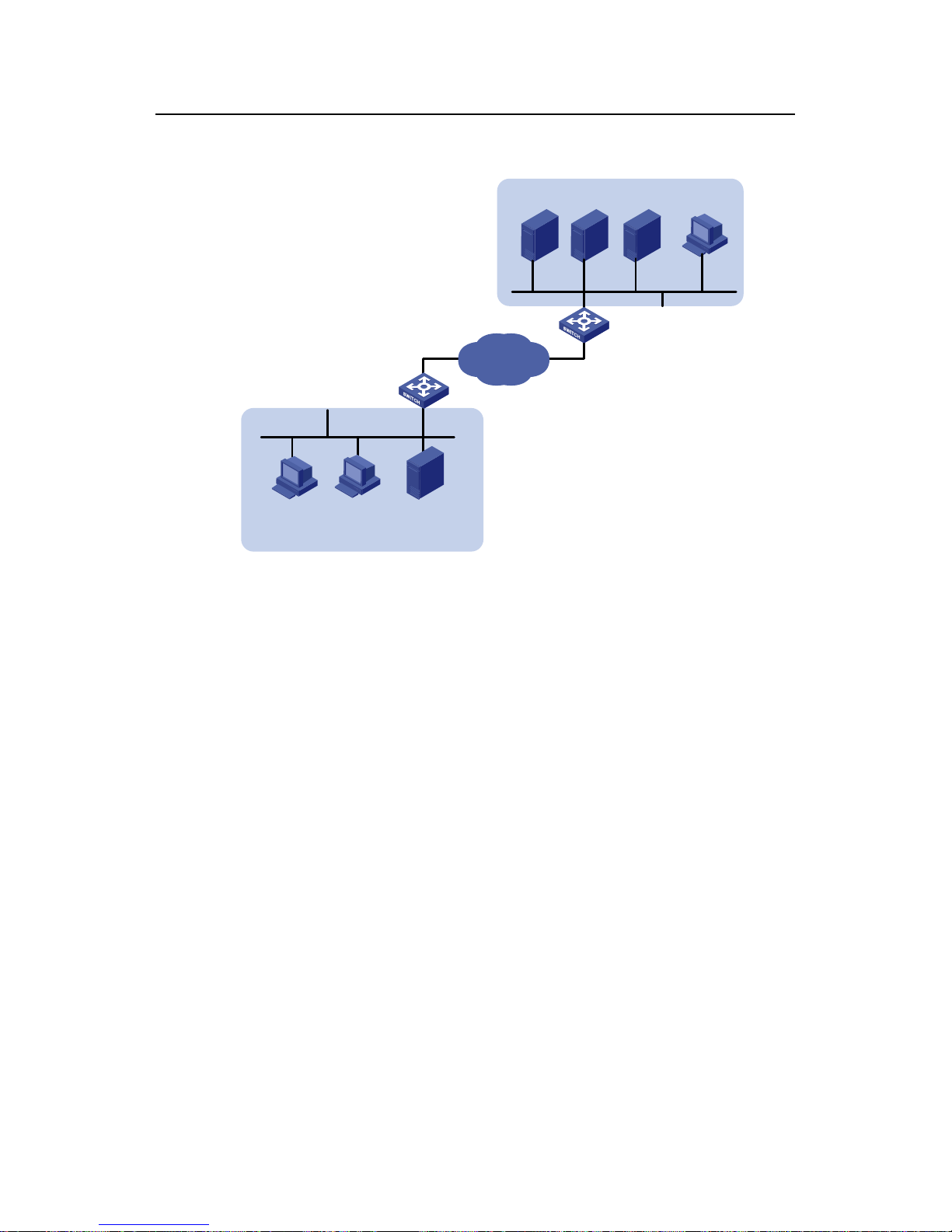
2.1.1 Network Requirements
An S3600 switch serves as the DHCP server in the corporate headquarters (HQ) to
allocate IP addresses to the workstations in the HQ and Branch, a nd it also act s as the
gateway to forward packets from the HQ. The network requirements are as follows:
z Assign the HQ the IP addresses in the 10.214.10.0/24 network segment, with a
lease period of two days, and exclude the IP addresses of the DNS server, WINS
server, and mail server from allocation.
z Assign IP addresses to the DNS server, WINS server, and the mail server in HQ
through static bindings.
z Assign the workstations in the Branch the IP addresses in the 10.210.10.0/24
network segment, with a lease period of three days, and assign the file server in
the Branch an IP address through a static IP-to-MAC binding.
z Assign the addresses of the gateway, DNS server, and the WINS server along
with an IP address to each workstation in the HQ and Branch.
z Enable the detection of unauthorized DHCP servers to prevent any unauthorized
DHCP server from allocating invalid addresses.
Page 14
DHCP
H3C Low-End Ethernet Switches Configuration Examples Chapter 2 Configuration Examples
2-2
2.1.2 Network Diagram
DHCP Relay
Gateway
DHCP
Client
WINS
Server
DNS
Server
Mail
Server
10.214.10.5
002e-8d20-54c6
10.214.10.3
000d-85c7-4e20
10.214.10.4
0013-4ca8-9b71
DHCP
Client1
DHCP
Client2
File Server
10.210.10.4
000d-88f8-4e71
Branch
HQ
IP network
VLAN-int10
VLAN-int100
Figure 2-1 Network diagram for DHCP server configuration
2.1.3 Configuration Procedure
I. Software Version Used
The S3600 Ethernet switches running software version Release 1510 are used in this
example.
II. Configuring DHCP server
z Configure address allocation for the devices in the HQ.
# Configure the IP address of VLAN-interface10 on the DHCP server in the HQ.
<H3C> system-view
[H3C] interface Vlan-interface 10
[H3C-Vlan-interface10] ip address 10.214.10.1 24
# Configure the interface to operate in the interface address pool mode, assigning the
IP addresses in the 10.214.10.0/24 network segment to the devices in the HQ.
[H3C-Vlan-interface10] dhcp select interface
# Configure the address lease period of the address pool, and configure the IP
addresses of the DNS server and WINS server.
[H3C-Vlan-interface10] dhcp server expired day 2
[H3C-Vlan-interface10] dhcp server dns-list 10.214.10.3
Page 15

DHCP
H3C Low-End Ethernet Switches Configuration Examples Chapter 2 Configuration Examples
2-3
[H3C-Vlan-interface10] dhcp server nbst-list 10.214.10.4
No gateway needs to be configured for the clients beca use an interface operating in the
interface address pool mode automatically serves as the gateway for DHCP client s and
sends the requested information to the clients.
# Assign IP addresses to the DNS server, WINS server, and mail server through
IP-to-MAC bindings.
[H3C-Vlan-interface10] dhcp server static-bind ip-address 10.214.10.3
mac-address 000d-85c7-4e20
[H3C-Vlan-interface10] dhcp server static-bind ip-address 10.214.10.4
mac-address 0013-4ca8-9b71
[H3C-Vlan-interface10] dhcp server static-bind ip-address 10.214.10.5
mac-address 002e08d20-54c6
# Exclude the static IP addresses of the DNS server , WINS server , and mail server from
allocation.
[H3C-Vlan-interface10] quit
[H3C] dhcp server forbidden-ip 10.214.10.3 10.214.10.5
z Configure address allocation for the devices in the Branch.
# Create a global address pool named “br” for the Branch, and specify the range and
lease period of the IP addresses for allocation.
[H3C] dhcp server ip-pool br
[H3C-dhcp-pool-br] network 10.210.10.0 mask 255.255.255.0
[H3C-dhcp-pool-br] expired day 3
# Create a static binding address pool named “br-static”, and assign the file server in
the Branch an IP address through an IP-to-MAC binding.
[H3C-dhcp-pool-br] quit
[H3C] dhcp server ip-pool br-static
[H3C-dhcp-pool-br-static] static-bind ip-address 10.214.10.4 mask
255.255.255.0
[H3C-dhcp-pool-br-static] static-bind mac-address 000d-88f8-4e71
# Specify the gateway address, DNS server address, and the WINS serve r address for
the workstations in the Branch.
[H3C-dhcp-pool-br-static] quit
[H3C] dhcp server ip-pool br
[H3C-dhcp-pool-br] gateway-list 10.210.10.1
[H3C-dhcp-pool-br] dns-list 10.214.10.3
[H3C-dhcp-pool-br] nbst-list 10.214.10.4
# Exclude the static IP address of the gateway in the Branch from allocation.
[H3C-dhcp-pool-br] quit
[H3C] dhcp server forbidden-ip 10.210.10.1
Page 16

DHCP
H3C Low-End Ethernet Switches Configuration Examples Chapter 2 Configuration Examples
2-4
# Enable the detection of unauthorized DHCP servers.
[H3C] dhcp server detect
# Configure VLAN-interface100 to operate in the global address pool mode.
[H3C] interface Vlan-interface 100
[H3C-Vlan-interface100] dhcp select global
Note that:
After DHCP configuration is complete, IP addresses can be assigned to the
workstations in the Branch only when a route is active between the HQ an d the Branch.
III. Configuring the DHCP relay agent
This section mainly describes the DHCP server configuration. The following shows the
basic DHCP relay agent configuration that ensures the DHCP relay agent to relay
DHCP requests to the DHCP server. For details about DHCP relay agent configuration,
see section
2.2 "DHCP Relay Agent/Snooping Configuration Examples".
<H3C> system-view
[H3C] dhcp-server 1 ip 10.214.10.1
[H3C] interface Vlan-interface 5
[H3C-Vlan-interface5] dhcp-server 1
2.2 DHCP Relay Agent/Snooping Configuration Examples
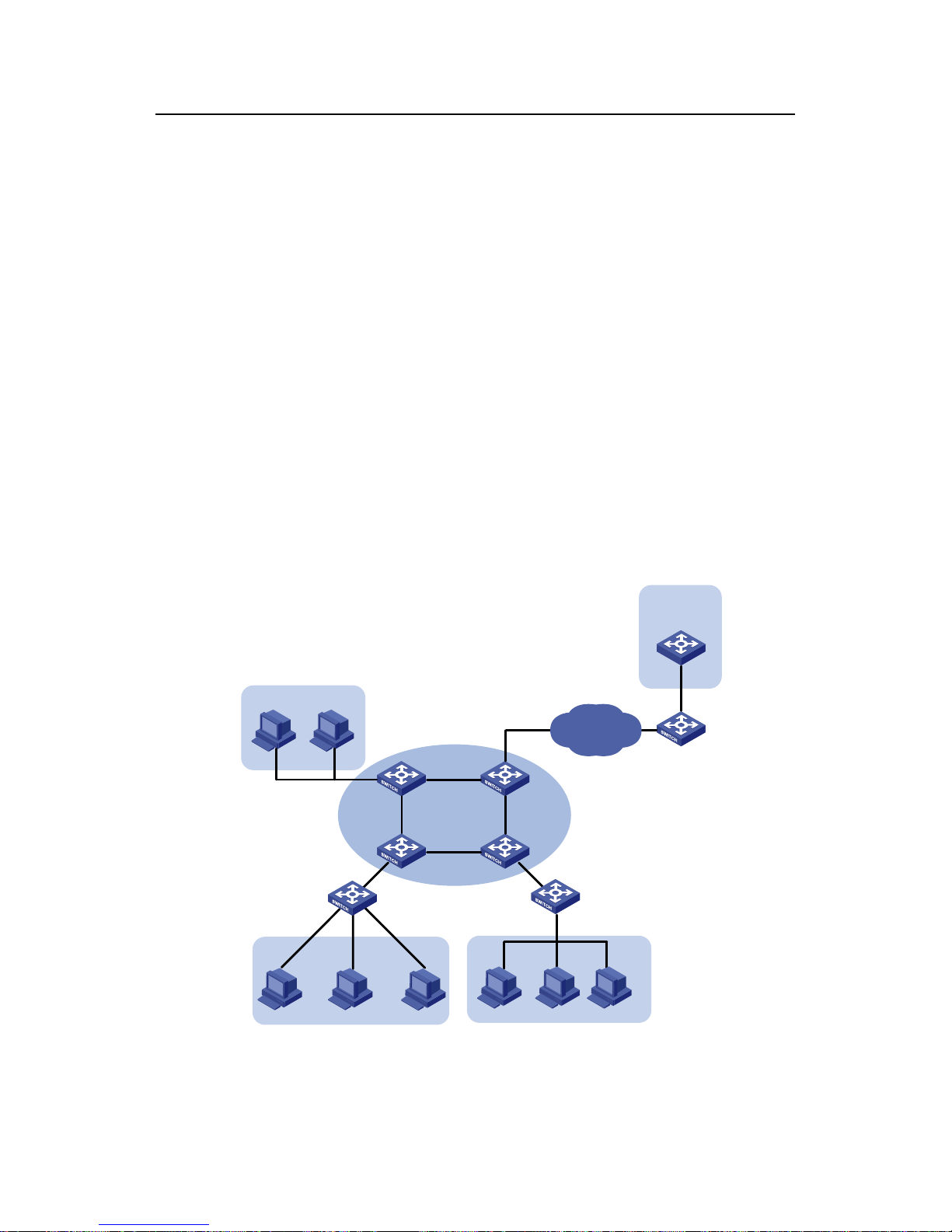
2.2.1 Network Requirements
A Cisco Cat al y st 3745 swit ch i s depl oye d in the HQ and serves a s the DHCP server to
assign IP addresses to the workstations in the Office branch. The branches are
connected to an IRF (intelligent resilient framework) Fabric that serves as the central
node and the DHCP relay agent to forward the DHCP requests from the workstations.
Meanwhile, a lab DHCP server is used to assign IP addresses to the devices in the labs.
The network requirements are as follows:
z Configure the DHCP server in the HQ to assign the IP addresses in the
192.168.10.0/24 network segment to the workstations in the Office branch, with a
lease period of 12 hours. Configure the IP addresses of the DNS server and WINS
server as 192.169.100.2 and 192.168.100.3 respectively.
z The IRF Fabric is connected to the branches and is comprised of four switches. It
serves as the DHCP relay agent to forward the DHCP requests from the
workstations in the Office and the devices in the labs. It is enabled to detect
unauthorized DHCP servers.
z An Ethernet switch in Lab1 serves as the Lab DHCP server to assign the IP
addresses in the 192.168.17.0/24 network segment to the devices in Lab1, with a
lease period of one day, and to assign the IP addresses in the 192.168.19.0/24
network segment to Lab2, with a lease period of two days. The lab DHCP server
Page 17
DHCP
H3C Low-End Ethernet Switches Configuration Examples Chapter 2 Configuration Examples
2-5
and the IRF Fabric are interconnected through the 172.16.2.4/30 network
segment.
z Configure the address checking function on the DHCP relay agent so that only the
devices that are assigned legal IP addresses from the DHCP server are allowed to
access the external network.
z Configure address entry update on the DHCP relay agent so that it updates the
address entries by sending requests to the DHCP server every one minute.
z Enable DHCP snooping to support DHCP Option 82, adding local port information
to the Option 82 field in DHCP messages.
z Enable the DHCP relay agent to support DHCP Option 82 so that the DHCP relay
agent keeps the original filed unchanged upon receiving DHCP messages
carrying Option 82.
z Enable the DHCP server to support DHCP Option 82 so that it assigns the IP
addresses 192.168.10.2 through 192.168.10.25 to the DHCP clients conne cted to
Ethernet1/0/11 on the DHCP snooping switch and assigns 192.168.10.100
through 192.168.10.150 to the DHCP clients connected to Ethernet1/0/12 of the
DHCP snooping switch.
2.2.2 Network Diagram
IP network
SwitchA
(Master)
SwitchB
(Unit2)
SwitchC
(Unit3)
SwitchD
(Unit4)
VLAN-int 10
192.168.10.1
Eth1/0/1
Eth1/0/11
Eth1/0/12
Eth1/0/13
VLAN-int 17
172.16.2.4/30
VLAN-int 15
192.168.17.1
0010-5ce9-1dea
IRF Fabric
DHCP Relay
VLAN-int 25
192.168.19.1
Lab2
HQ
Office Lab1
Lab DHCP Server
DHCP Snooping
Cisco Catalyst
3745
192.168.0.3
Figure 2-2 Network diagram for DHCP relay agent/snooping integrated configuration
Page 18

DHCP
H3C Low-End Ethernet Switches Configuration Examples Chapter 2 Configuration Examples
2-6
2.2.3 Configuration Procedure
In this example, the IRF Fabric is comprised of S3600 switches running software
version Release 1510, a Quidway S3552 switch running software version Release
0028 is used as the DHCP snooping-capable switch, and a Quidway S3528 switch
running software version Release 0028 is used as the Lab DHCP server.
For better readability:
z The devices in the IRF Fabric are SwitchA, SwitchB, SwitchC, and SwitchD.
z The DHCP snooping-capable device is referred to as “Snooping”.
z The device serving as the Lab DHCP server is referred to as “LAB”.
I. Configuring IRF Fabric
The S3600 series support IRF Fabric. You can interconnect four devices to form a
Fabric for centralized management of the devices in the Fabric. For det ails, see related
sections in the operation manuals for the S3600 series.
II. Configuring the DHCP relay agent
Figure 2-3 Network diagram for DHCP relay agent configuration
Within the IRF Fabric, configuration made on a device can be synchronized to the other
devices. Therefore, configuration is performed on Switch A only in this example.
# Configure to forward the DHCP requests from the Office to the DHCP server in the
HQ.
<SwitchA> system-view
[SwitchA] dhcp-server 1 ip 192.168.0.3
[SwitchA] interface vlan-interface10
[SwitchA-Vlan-interface10] ip address 192.168.10.1 24
[SwitchA-Vlan-interface10] dhcp-server 1
# Configure to forward the DHCP requests from Lab2 to the Lab DHCP server.
[SwitchA-Vlan-interface10] quit
[SwitchA] dhcp-server 2 ip 192.168.17.1
[SwitchA] interface Vlan-interface 25
[SwitchA-Vlan-interface25] ip address 192.168.19.1 24
Page 19

DHCP
H3C Low-End Ethernet Switches Configuration Examples Chapter 2 Configuration Examples
2-7
[SwitchA-Vlan-interface25] dhcp-server 2
# Configure the IP address of VLAN-interface17 as 172.16.2.5/30 for forwarding DHCP
packets from the Lab DHCP Server to a non-local segment.
[SwitchA-Vlan-interface25] quit
[SwitchA] interface Vlan-interface 17
[SwitchA-Vlan-interface17] ip add 172.16.2.5 30
# Configure the address checking function on the DHCP relay agent. Make sure you
configure the IP addresses and MAC addresses of the two DHCP servers as static
entries for the security function.
[SwitchA-Vlan-interface17] quit
[SwitchA] dhcp-security static 192.168.0.3 000D-88F8-4E71
[SwitchA] dhcp-security static 192.168.17.1 0010-5ce9-1dea
[SwitchA] interface Vlan-interface 10
[SwitchA-Vlan-interface10] address-check enable
[SwitchA-Vlan-interface10] quit
[SwitchA] interface vlan-interface 25
[SwitchA-Vlan-interface25] address-check enable
[SwitchA-Vlan-interface25] quit
# Configure the address entry update interval on the DHCP relay agent.
[SwitchA] dhcp relay hand enable
[SwitchA] dhcp-security tracker 60
# Enable the DHCP relay agent to support DHCP Option 82 and adopt the strategy of
keeping the original filed upon receiving DHCP messages carrying Option 82.
[SwitchA] dhcp relay information enable
[SwitchA] dhcp relay information strategy keep
# Enable the DHCP relay agent to detect unauthorized DHCP servers.
[SwitchA] dhcp-server detect
# Enable UDP-Helper so that the IRF Fabric can operate in the DHCP relay agent
mode.
[SwitchA] udp-helper enable
# To ensure normal forwarding of DHCP packets across network segments, you need
configure a routing protocol and advertise the network segments of interfaces. The
following configuration uses RIP as an example. For the configuration of other routing
protocols, see the parts covering routing protocols in product manuals.
[SwitchA] rip
[SwitchA-rip] network 192.168.10.0
[SwitchA-rip] network 192.168.19.0
[SwitchA-rip] network 172.16.0.0
Page 20
DHCP
H3C Low-End Ethernet Switches Configuration Examples Chapter 2 Configuration Examples
2-8
Note:
For the DHCP relay agent using the IRF structure and the DHCP server in the HQ to
communicate with each other, an active route must also be configured between them.
This configuration is performed by the ISP or the user; therefore, it will not be covered
in this document.
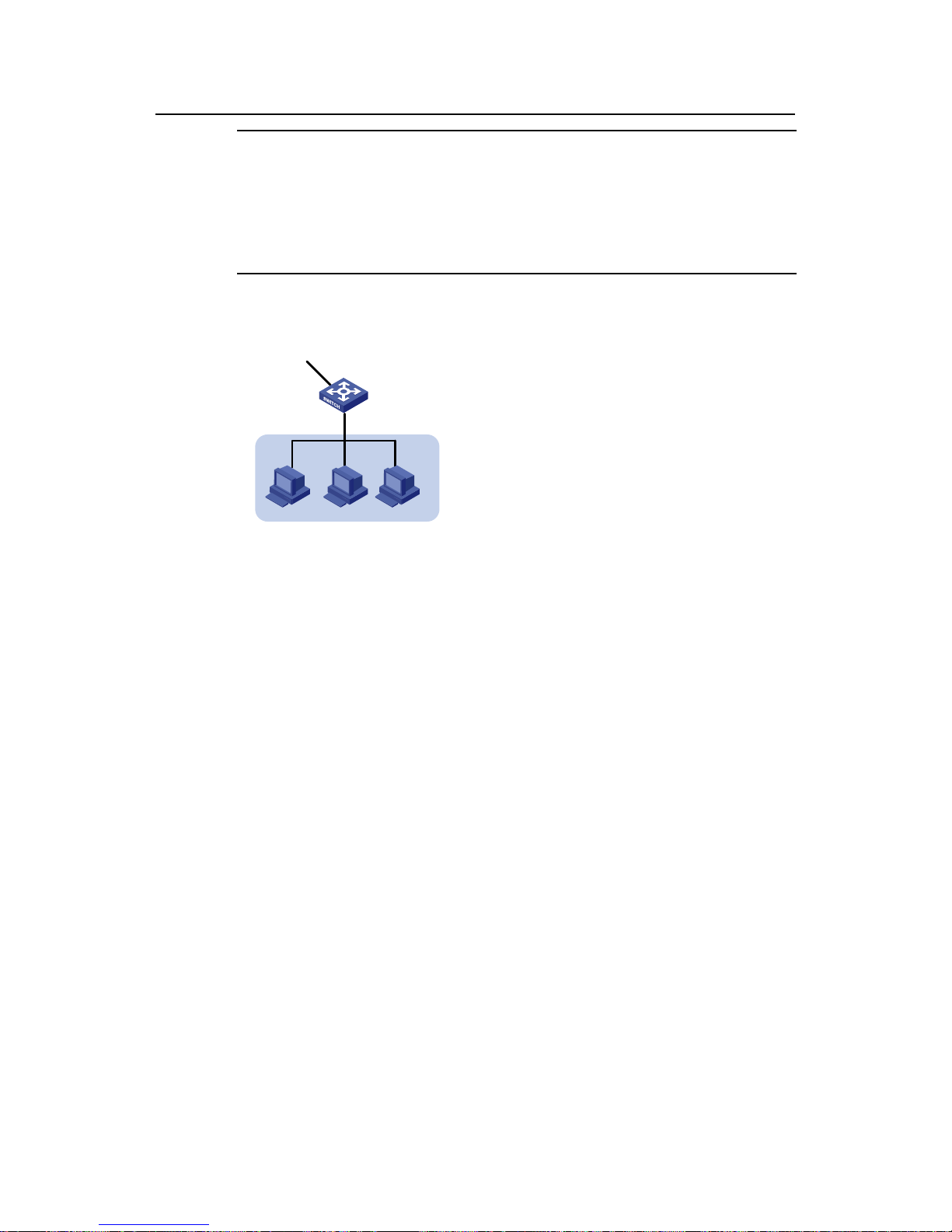
III. Configuring the Lab DHCP server
VLAN-int 15
192.168.17.1
0010-5ce9-1dea
Lab1
VLAN-int 17
172.16.2.4/30
Figure 2-4 Network diagram for the Lab DHCP server configuration
# Configure an address pool for Lab2 and specify the address rang e, lease period, and
the gateway address.
<LAB> system-view
[LAB] dhcp enable
[LAB] dhcp server ip-pool lab2
[LAB-dhcp-lab2] network 192.168.19.0 255.255.255.0
[LAB-dhcp-lab2] expired day 2
[LAB-dhcp-lab2] gateway-list 192.168.19.1
# Configure the IP address of VLAN-interface17 as 172.16.2.6/30 and enable it to
operate in global address pool mode.
[LAB-dhcp-lab2] quit
[LAB] interface Vlan-interface 17
[LAB-Vlan-interface17] ip address 172.16.2.6 30
[LAB-Vlan-interface17] dhcp select global
# Lab1 is connected to VLAN-interface15. Therefore, to assign the IP addre sses in the
192.168.17.0/24 network segment to the devices in Lab1, you only need to configure
VLAN-interface15 to operate in the interface address pool mode.
[LAB-Vlan-interface17] quit
[LAB] interface vlan-interface 15
[LAB-Vlan-interface15] ip address 192.168.17.1 24
Page 21
DHCP
H3C Low-End Ethernet Switches Configuration Examples Chapter 2 Configuration Examples
2-9
[LAB-Vlan-interface15] dhcp select interface
[LAB-Vlan-interface15] quit
# To ensure that the lab DHCP server forwards DHCP packets normally, you need
configure a routing protocol. The following configuration uses RIP as an example. For
the configuration of other routing protocols, see the related parts in product manuals.
[LAB] rip
[LAB-rip] network 192.168.17.0
[LAB-rip] network 172.16.0.0
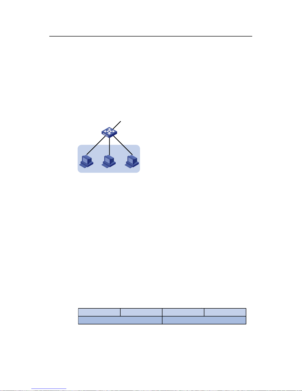
IV. Configuring DHCP snooping
Eth1/0/1
Eth1/0/11
Eth1/0/12
Eth1/0/13
Office
DHCP Snooping
Figure 2-5 Network diagram for DHCP snooping configuration
# Enable DHCP snooping and enable Option 82 support for DHCP snooping.
<Snooping> system-view
[Snooping] dhcp-snooping
[Snooping] dhcp-snooping information enable
[Snooping] dhcp-packet redirect Ethernet 0/11 to 0/13
V. Configuring the DHCP server in the HQ
# On the H3C series switches, port numbers, VLAN numbers, and the MAC addresses
of the DHCP snooping device and the DHCP relay agent are added to DHCP Option 82.
A complete piece of Option 82 information is a combination of the values of two
suboptions:
Circuit ID suboption: It identifies the VLAN to which the clients belong and the port to
which the DHCP snooping device is connected.
0 31
Type(1)
15
VLAN ID
Length(6) 0 4
Port Index
Figure 2-6 Packet structure of Circuit ID suboption
Page 22

DHCP
H3C Low-End Ethernet Switches Configuration Examples Chapter 2 Configuration Examples
2-10
For example, the DHCP messages from clients conne cted to Ethernet1/0/1 1 a re added
with Option 82, whose Circuit ID suboption should be 0x010600040001000a, where
01060004 is a fixed value, 0001 indicates the access port’ s VLAN is VLAN 1, and 000a
is the absolute number of the port, which is 1 less than the actual port number,
indicating the actual port is Ethernet1/0/11.
Remote ID suboption: It identifies the MAC address of the DHCP snooping device
connected to the client.
0 31
Type(2)
15
Bridge MAC Address
Length(8) 0 6
Figure 2-7 Packet structure of Remote ID suboption
For example, the DHCP messages from clients connected to the DHCP snooping
device with MAC 000f-e234-bc66 are added with Option 82, whose Remote ID
suboption should be 02080006000fe234bc66, where 02080006 is a fixed value and
000fe234bc66 is the MAC address of the DHCP snoo ping device.
In this example, IP addresses are assigned based on port number only. Therefore, on
the DHCP server , only a matching port number field in the Circuit ID suboption needs to
be found.
Note:
The following configuration is performed on the Cisco Catalyst 3745 switch running IOS
version 12.3(11)T2. If you are using any other models or devices running any other
version, see the user manuals provided with the devices.
# Enable DHCP server and allocate IP addresses using Option 82 information.
Switch> enable
Switch(config)# configure terminal
Enter Configuration commands, one per line. End with CNTL/Z.
Switch(config)# service dhcp
Switch(config)# ip dhcp use class
# Create a DHCP class for the client connected to Ethernet1/0/11 of the DHCP
snooping device and match the port number in the Circuit ID suboption of Option82,
and replace the contents without match need with a wildcard "*".
Switch(config)# ip dhcp class office1
Switch(dhcp-class)# relay agent information hex 010600040001000a*
Page 23

DHCP
H3C Low-End Ethernet Switches Configuration Examples Chapter 2 Configuration Examples
2-11
Switch(dhcp-class)# exit
# Configure a DHCP class for the client connected to Etherent1/0/12 of the DHCP
snooping device and match the port number in the Circuit ID suboption of Option82.
Switch(config)# ip dhcp class office2
Switch(dhcp-class)# relay agent information hex 010600040001000b*
# Create an address pool for Office and specify address ranges for the two DHCP
classes.
Switch(config)# ip dhcp pool office
Switch(dhcp-pool)# network 192.168.10.0
Switch(dhcp-pool)# class office1
Switch(dhcp-pool-class)# address range 192.168.10.2 192.168.10.25
Switch(dhcp-pool-class)# exit
Switch(dhcp-pool)# class office2
Switch(dhcp-pool-class)# address range 192.168.10.100 192.168.10.150
Switch(dhcp-pool-class)# exit
# Configure the lease period, gateway address, DNS server address, and WINS server
address for the address pool.
Switch(dhcp-pool)# lease 0 12
Switch(dhcp-pool)# default-router 192.168.10.1
Switch(dhcp-pool)# dns-server 192.168.100.2
Switch(dhcp-pool)# netbios-name-server 192.168.100.3
After the above-mentioned configuration, the DHCP server can automatically assign an
IP address, the gateway address, DNS server address, and the WINS server address
for each device in Office.
2.3 Precautions
2.3.1 Cooperation Between DHCP Relay Agent and IRF
z In an IRF network, the DHCP relay agent runs on all the units in the Fabric. But
only the DHCP relay agent running on the master unit can receive and send
packets to perform full DHCP relay agent functions. The DHCP relay agent
running on a slave unit, however, only serves as a backup for the master unit.
z DHCP is an application-layer protocol based on UDP. Once a slave unit receives a
DHCP request, UDP-Helper redirects the packet to the master unit. Then, the
DHCP relay agent running on the master unit gives a response back to the request
and sends the real time information to each slave unit for backup. In this way,
when the current master unit fails, one of the slaves becomes the new master and
operates as the DHCP relay agent immediately. Therefore, make sure you enable
UDP-Helper before using DHCP relay agent in an IRF system.
Page 24

DHCP
H3C Low-End Ethernet Switches Configuration Examples Chapter 3 Related Documents
3-1
Chapter 3 Related Documents
3.1 Protocols and Standards
z RFC2131: Dynamic Host Configuration Protocol
z RFC2132: DHCP Options and BOOTP Vendor Extensions
z RFC3046: DHCP Relay Agent Information Option
Page 25

QACL
H3C Low-End Ethernet Switches Configuration Examples Table of contents
i
Table of Contents
Chapter 1 QACL Overview............................................................................................................ 1-1
1.1 Supported QACL Functions...............................................................................................1-1
1.1.1 ACL/QoS Functions Supported by H3C Low-End Ethernet Switches....................1-1
1.2 Configuration Guide........................................................................................................... 1-3
Chapter 2 Examples of QACL Configuration.............................................................................. 2-1
2.1 Network Environment ........................................................................................................ 2-1
2.2 Time-based ACL plus Rate Limiting plus Traffic Policing Configuration Example............2-2
2.2.1 Network Requirements............................................................................................ 2-2
2.2.2 Network Diagram.....................................................................................................2-2
2.2.3 Configuration Procedure......................................................................................... 2-2
2.3 Configuration Example of Priority Re-marking plus Queue Scheduling Algorithm plus
Congestion Avoidance plus Packet Priority Trust....................................................................
2-4
2.3.1 Network Requirements............................................................................................ 2-4
2.3.2 Network Diagram.....................................................................................................2-4
2.3.3 Configuration Procedure......................................................................................... 2-4
2.4 Configuration Example of Traffic Measurement plus Port Redirection.............................. 2-5
2.4.1 Network Requirements............................................................................................ 2-5
2.4.2 Network Diagram.....................................................................................................2-6
2.4.3 Configuration Procedure......................................................................................... 2-6
2.5 Configuration Example of Local Traffic Mirroring .............................................................. 2-7
2.5.1 Network Requirements............................................................................................ 2-7
2.5.2 Network Diagram.....................................................................................................2-7
2.5.3 Configuration Procedure......................................................................................... 2-8
2.6 Precautions........................................................................................................................ 2-8
2.7 Other Functions Referencing ACL Rules .......................................................................... 2-9
Chapter 3 Configuration Example of WEB Cache Redirection................................................. 3-1
3.1 Configuration Example of WEB Cache Redirection ..........................................................3-1
3.1.1 Network Requirements............................................................................................ 3-1
3.1.2 Network Diagram.....................................................................................................3-2
3.1.3 Configuration Procedure......................................................................................... 3-2
Page 26

QACL
H3C Low-End Ethernet Switches Configuration Examples Abstract
ii
QACL Configuration Examples
Key words: ACL, and QoS
Abstract: This document describes QACL configurations on Ethernet switches in actual
networking environments. To satisfy different user needs, the document covers
various functions and applications like time-based ACLs, traffic policing, priority
re-marking, queue scheduling, traffic measurement, port redirection, local traffic
mirroring, and WEB Cache redirection.
Acronyms: Access control list (ACL), and quality of service (QoS)
Page 27

QACL
H3C Low-End Ethernet Switches Configuration Examples Chapter 1 QACL Overview
1-1
Chapter 1 QACL Overview
1.1 Supported QACL Functions
1.1.1 ACL/QoS Functions Supported by H3C Low-End Ethernet Switches
Table 1-1 ACL/QoS functions supported by H3C low-end ethernet switches
Model
Function
S3600-EI S3600-SI S5600 S5100-EI S5100-SI
S3100-
SI
Basic ACL
z
z
z
z
z
z
Advanced
ACL
z
z
z
z
z
z
Layer 2 ACL
z
z
z
z
—
—
User-defined
ACL
z
z
z
—
—
—
Software-bas
ed ACL
referenced by
upper-layer
software
z
z
z
z
z
z
Apply
hardware-bas
ed ACL to
hardware
z
z
z
z
—
—
Traffic
classification
z
z
z
z
—
—
Priority
re-marking
z
z
z
z
—
—
Port rate
limiting
z
z
z
—
z
z
Traffic policing
z
z
z
z
—
—
Traffic
shaping
—
—
—
z
—
—
Port
redirection
z
z
z
z
—
—
Queue
scheduling
z
z
z
z
z
z
Congestion
avoidance
z
z
—
—
—
—
Page 28

QACL
H3C Low-End Ethernet Switches Configuration Examples Chapter 1 QACL Overview
1-2
Model
Function
S3600-EI S3600-SI S5600 S5100-EI S5100-SI
S3100-
SI
Local traffic
mirroring
z
z
z
z
—
—
Traffic
measurement
z
z
z
z
—
—
WEB Cache
redirection
z
—
—
—
—
—
Note:
z means that the function is supported.
— means that the function is not supported.
Note:
For details on ACL/QoS functions supported by different models, refer to
corresponding operation manuals.
Page 29

QACL
H3C Low-End Ethernet Switches Configuration Examples Chapter 1 QACL Overview
1-3
1.2 Configuration Guide
Note:
z ACL/QoS configuration varies with switch models. The configuration below takes an
H3C S3600 Ethernet Switch as an example. For ACL/QoS configuration on other
switches, refer to corresponding user manuals.
z The section below only lists basic configuration steps. For the operating principle
and detailed information of each function, refer to the operation manual and
command manual of each product.
Table 1-2 Configure ACL/QoS in system view
Configuration Command Remarks
Create an ACL and
enter ACL view
acl number acl-number
[ match-order { config |
auto } ]
By default, the matching
order is config.
Layer 2 ACLs and
user-defined ACLs do not
support match-order.
Define an ACL rule
rule [ rule-id ] { permit |
deny } rule-string
The parameters (criteria)
available for rule-string vary
with ACL types. For details,
refer to the corresponding
command manual.
Configure a queue
scheduling algorithm in
system view
queue-scheduler
{ strict-priority | wfq
queue0-width
queue1-width
queue2-width
queue3-width
queue4-width
queue5-width
queue6-width
queue7-width | wrr
queue0-weight
queue1-weight
queue2-weight
queue3-weight
queue4-weight
queue5-weight
queue6-weight
queue7-weight }
z If the weight or minimum
bandwidth of a queue is
set to 0 in the WRR or
WFQ approach, strict
priority queuing applies
to the queue.
z By default, the WRR
queue scheduling
algorithm is used for all
outbound queues on a
port. Default weights
are 1:2:3:4:5:9:13:15.
z The queue scheduling
algorithm defined using
the queue-scheduler
command in system
view will work on all
ports.
Configure congestion
avoidance
wred queue-index qstart
probability
—
Page 30

QACL
H3C Low-End Ethernet Switches Configuration Examples Chapter 1 QACL Overview
1-4
Table 1-3 Configure ACL/QoS in port view
Configuration Command Remarks
Apply an ACL on a port
packet-filter { inbound |
outbound } acl-rule
—
Configure the switch to
trust the priority of
received packets
priority trust
Configure the switch to
trust the priority carried in
received packets.
Configure port-based rate
limit
line-rate { inbound |
outbound } target-rate
The granularity is 64
kbps. If an entered
number is in the range
N×64 to (N+1)×64 (N is a
natural number), the
switch takes the value
(N+1)×64.
Reference an ACL for
traffic identification, and
re-assign a priority to the
matching packets
traffic-priority { inbound
| outbound } acl-rule
{ { dscp dscp-value |
ip-precedence
{ pre-value | from-cos } } |
cos { pre-value |
from-ipprec } |
local-precedence
pre-value }*
You can re-mark the IP
priority, 802.1p priority,
DSCP priority of packets,
and the priority of local
queues.
Configure traffic policing
traffic-limit inbound
acl-rule target-rate
[ exceed action ]
exceed action: specifies
the action taken on the
excess packets when the
packet traffic exceeds the
preset limit.
z drop: Drop the
excess packets.
z remark-dscp value:
Re-set the DSCP
priority, and forward
the packets.
Page 31

QACL
H3C Low-End Ethernet Switches Configuration Examples Chapter 1 QACL Overview
1-5
Configuration Command Remarks
Configure a queue
scheduling algorithm in
port view
queue-scheduler { wfq
queue0-width
queue1-width
queue2-width
queue3-width
queue4-width
queue5-width
queue6-width
queue7-width | wrr
queue0-weight
queue1-weight
queue2-weight
queue3-weight
queue4-weight
queue5-weight
queue6-weight
queue7-weight }
z The queue
scheduling
algorithm defined
using the
queue-scheduler
command in
Ethernet port view
will work on the
current port only.
z In the globally
defined WRR or
WFQ queue
scheduling
algorithm, you can
modify the weight or
bandwidth in port
view if the weight or
bandwidth of each
queue cannot
satisfy the needs of
a port.
z Queue weight or
bandwidth defined
in port view take
priority over the
global settings.
z The queue weight or
bandwidth defined
in port view cannot
be displayed using
the display
queue-scheduler
command.
Configure redirection
traffic-redirect
{ inbound | outbound }
acl-rule { cpu | interface
interface-type
interface-number }
A packet cannot be
forwarded normally if it is
redirected to the CPU.
Reference an ACL for
traffic identification, and
measure the traffic of the
matching packets
traffic-statistic inbound
acl-rule
—
Page 32

QACL
H3C Low-End Ethernet Switches Configuration Examples Chapter 2 Examples of QACL Configuration
2-1
Chapter 2 Examples of QACL Configuration
2.1 Network Environment
PC 1
Server 1
Data Detect Server
LAN 1
LAN 12LAN 10
PC 4
PC 3PC 2
LAN 11 LAN 12
E1/0/1 E1/0/4
E1/0/3E1/0/2
E1/0/20
GE1/1/2
GE1/1/1
LAN 2
Server 4Server 3Server 2
10.0.0.1
10.0.0.410.0.0.310.0.0.2
10.0.0.10 10.0.0.13
10.0.0.1210.0.0.11
0012-a990-2440 0012-a990-2443
0012-a990-24420012-a990-2441
Figure 2-1 Network topology
Figure 2-1 shows the network topology of a company. The environment is as follows:
z An S3600 switch serves as the central switch of the company. The software
version is Release 1510.
z The devices within the company gain access to the Internet through Server1
attached to the port GigabitEthernet1/1/1.
z Server2, Server3, and Server4 are the data server, mail server and file server of
the company respectively. They are connected to the port GigabitEthernet1/1/2.
z The Data Detect Server is connected to the port Ethernet1/0/20.
z PC1, PC2, PC3 and PC4 are clients of the company, and are connected to the
ports Ethernet1/0/1, Ethernet1/0/2, Ethernet1/0/3, and Ethernet1/0/4 respectively.
Page 33

QACL
H3C Low-End Ethernet Switches Configuration Examples Chapter 2 Examples of QACL Configuration
2-2
2.2 Time-based ACL plus Rate Limiting plus Traffic Policing
Configuration Example
2.2.1 Network Requirements
The company gains access to the Internet through Server1. The requirements are as
follows:
z During the period from 8:30 to 18:30 in workdays, the clients are not allowed to
access the Internet through HTTP. In other periods, the clients are allowed to
access the Internet. The maximum access traffic is 100 Mbps.
z For the packets with the IP priority of 7 that are sent by PC 1, the allowed
maximum rate is 20 Mbps. The DSCP priority of such packets at rates higher than
20 Mbps is modified as EF.
z For the packets with the CoS priority of 5 that are sent by PC 2, the allowed
maximum rate is 10 Mbps. Such packets at rates higher than 10 Mbps are
discarded.
2.2.2 Network Diagram
PC 1
Server 1
LAN 1
LAN 12LAN 10
PC 4
PC 3PC 2
LAN 11 LAN 12
E1/0/1 E1/0/4
E1/0/3E1/0/2
E1/0/20
GE1/1/2
GE1/1/1
10.0.0.1
10.0.0.10 10.0.0.13
10.0.0.1210.0.0.11
0012-a990-2440 0012-a990-2443
0012-a990-24420012-a990-2441
Figure 2-2 Network diagram for configuration of time-based ACL plus port-based
bandwidth limiting plus traffic policing
2.2.3 Configuration Procedure
# Create time range a001, defining the office hours on working days.
<H3C> system-view
System View: return to User View with Ctrl+Z.
Page 34

QACL
H3C Low-End Ethernet Switches Configuration Examples Chapter 2 Examples of QACL Configuration
2-3
[H3C] time-range a001 8:30 to 18:00 working-day
# Create time range a002, defining off hours.
[H3C] time-range a002 00:00 to 8:30 working-day
[H3C] time-range a002 18:00 to 24:00 working-day
[H3C] time-range a002 00:00 to 24:00 off-day
# Define ACL 3010: Forbid the clients to access the Internet through HTTP during the
time range a001; classify and mark the packet s with the IP priority of 7 gen erated when
PC 1 accesses the Internet during non-workday periods.
[H3C] acl number 3010
[H3C-acl-adv-3010] rule 0 deny tcp destination 10.0.0.1 0 destination-port eq
80 time-range a001
[H3C-acl-adv-3010] rule 1 permit ip source 10.0.0.10 0 precedence 7 time-range
a002
[H3C-acl-adv-3010] quit
# Define ACL 4010: Classify and mark the packet s wit h the CoS priority of 5 generated
when PC 2 accesses the Internet during non-work periods.
[H3C] acl number 4010
[H3C-acl-ethernetframe-4010] rule 0 permit cos 5 source 0012-0990-2241
ffff-ffff-ffff time-range a002
[H3C-acl-ethernetframe-4010] quit
# Apply rule 0 of ACL 3010 to the port GigabitEthernet1/1/1 con nected t o Server1, and
set the maximum traffic rate by clients’ accessing the Internet to 100 Mbps.
[H3C] interface GigabitEthernet 1/1/1
[H3C-GigabitEthernet1/1/1] packet-filter outbound ip-group 3010 rule 0
[H3C-GigabitEthernet1/1/1] line-rate outbound 102400
[H3C-GigabitEthernet1/1/1] quit
# Perform traffic policing for the packets marked rule 1 of ACL 3010 on the port
Ethernet1/0/1 connected to PC 1, and modify the DSCP priority of the excess packets
to EF.
[H3C] interface Ethernet 1/0/1
[H3C-Ethernet1/0/1] traffic-limit inbound ip-group 3010 rule 1 20480 exceed
remark-dscp ef
[H3C-Ethernet1/0/1] quit
# Perform traffic policing for the packets marked rule 0 of ACL 4010 on the port
Ethernet1/0/2 connected to PC 2, set the maximum traffic rate to 10 Mbps, and discard
the excess packets.
[H3C] interface Ethernet 1/0/2
[H3C-Ethernet1/0/2] traffic-limit inbound link-group 4010 rule 0 10240 exceed
drop
Page 35

QACL
H3C Low-End Ethernet Switches Configuration Examples Chapter 2 Examples of QACL Configuration
2-4
Note: The traffic-limit command works only with the permit rules in ACLs.
2.3 Configuration Example of Priority Re-marking plus
Queue Scheduling Algorithm plus Congestion Avoidance
plus Packet Priority Trust
2.3.1 Network Requirements
Server2, Server3, and Server4 are the data server, mail server and file server of the
company respectively. The detailed requirements are as follows:
z The switch first processes the packets accessing the data server, th en the packets
accessing the mail server, and finally the packet accessing the file server.
z Configure the port GigabitEthernet1/1/2 to use the WRR queue priority algorithm,
and configure the weight of outbound queues as 1:1:1:5:1:10:1:15.
z Configure the queue with an index of 4 on the port GigabitEthernet1/1/2 to use
WRED: Discard subsequent packets at random when the queue is more than 64
packets in size, and configure the probability of discarding as 20%.
z Configure the port Ethernet1/0/3 to trust the priority of packets rather than to use
the priority of the port.
2.3.2 Network Diagram
GE1/1/2
LAN 2
Server 4Server 3Server 2
10.0.0.410.0.0.310.0.0.2
Figure 2-3 Network diagram for configuration of priority re-marking plus queue
scheduling algorithm plus congestion avoidance plus packet priority trust
2.3.3 Configuration Procedure
# Define ACL 3020: Classify and mark packets according to their destination IP
addresses.
Page 36

QACL
H3C Low-End Ethernet Switches Configuration Examples Chapter 2 Examples of QACL Configuration
2-5
<H3C> system-view
System View: return to User View with Ctrl+Z.
[H3C] acl number 3020
[H3C-acl-adv-3020] rule 0 permit ip destination 10.0.0.2 0
[H3C-acl-adv-3020] rule 1 permit ip destination 10.0.0.3 0
[H3C-acl-adv-3020] rule 2 permit ip destination 10.0.0.4 0
[H3C-acl-adv-3020] quit
# Re-mark priority for the packets on th e port GigabitEthernet1/1/2 that match the rules
in ACL 3020.
[H3C] interface GigabitEthernet 1/1/2
[H3C-GigabitEthernet1/1/2] traffic-priority outbound ip-group 3020 rule 0
local-precedence 7
[H3C-GigabitEthernet1/1/2] traffic-priority outbound ip-group 3020 rule 1
local-precedence 5
[H3C-GigabitEthernet1/1/2] traffic-priority outbound ip-group 3020 rule 2
local-precedence 3
# Configure the WRR queue scheduling algorithm on the port GigabitEthernet1/1/2,
and configure the weight of outbound queues as 1:1:1:5:1:10:1:15.
[H3C-GigabitEthernet1/1/2] queue-scheduler wrr 1 1 1 5 1 10 1 15
# Configure the queue with an index of 4 on the port GigabitEthernet1/1/2 to use WRED:
Discard subsequent packets at ra ndom when the queue is more than 64 p ackets in size,
and configure the probability of discarding as 20%.
[H3C-GigabitEthernet1/1/2] wred 4 64 20
[H3C-GigabitEthernet1/1/2] quit
# Configure the port Ethernet1/0/3 connected to PC 3 to trust the 802.1p priority carried
by packets.
[H3C] interface Ethernet 1/0/3
[H3C-Ethernet1/0/3] priority trust
Note: The traffic-priority command works only with the permit rules in ACLs.
2.4 Configuration Example of Traffic Measurement plus Port
Redirection
2.4.1 Network Requirements
The Data Detect Server is connected to the port Ethernet1/0/20. The detailed
requirements are as follows:
z Measure the HTTP traffic generated by Internet access through the port
Ethernet1/0/1 during non-workday periods.
Page 37
QACL
H3C Low-End Ethernet Switches Configuration Examples Chapter 2 Examples of QACL Configuration
2-6
z Redirect all the HTTP traffic generated by the Internet access through the port
Ethernet1/0/1 during workday period to the port Ethernet1/0/20.
2.4.2 Network Diagram
PC 1
E1/0/1
E1/0/20
10.0.0.10
0012-a990-2440
LAN 10
Data Detect Server
Figure 2-4 Network diagram for configuration of traffic measurement plus port
redirection
2.4.3 Configuration Procedure
# Configure a workday period.
<H3C> system-view
System View: return to User View with Ctrl+Z.
[H3C] time-range a001 8:30 to 18:00 working-day
# Configure non-workday periods.
[H3C] time-range a002 00:00 to 8:30 working-day
[H3C] time-range a002 18:00 to 24:00 working-day
[H3C] time-range a002 00:00 to 24:00 off-day
# Define ACL 3030: Classify the packets accessing the Internet through HTTP
according to periods.
[H3C] acl number 3030
[H3C-acl-adv-3030] rule 0 permit tcp destination 10.0.0.1 0 destination-port
eq 80 time-range a001
[H3C-acl-adv-3030] rule 1 permit tcp destination 10.0.0.1 0 destination-port
eq 80 time-range a002
Page 38

QACL
H3C Low-End Ethernet Switches Configuration Examples Chapter 2 Examples of QACL Configuration
2-7
# Configure traffic redirection on the port Ethernet1/0/1: Redirect all the HTTP traffic
generated by Internet access during workday period to the port Ethernet1/0/20.
[H3C] interface Ethernet 1/0/1
[H3C-Ethernet1/0/1] traffic-redirect inbound ip 3030 rule 0 interface Ethernet
1/0/20
# Measure the HTTP traffic generated by Internet access during non-workday periods
on the port Ethernet1/0/1.
[H3C-Ethernet1/0/1] traffic-statistic inbound ip-group 3030 rule 1
Note: The traffic-redirect and traffic-statistic commands work only with the permit
rules in ACLs.
2.5 Configuration Example of Local Traffic Mirroring
2.5.1 Network Requirements
The Data Detect Server is connected to the port Ethernet1/0/20. All the packets
accessing the Internet through the ports Ethernet1/0/1 and Ethernet1/0/2 using HTTP
during workday period must be mirrored to the port Ethernet1/0/20. Then, the Data
Detect Server analyzes the packets.
2.5.2 Network Diagram
PC 1
Data Detect Server
LAN 10
PC 2
LAN 11
E1/0/1
E1/0/2
E1/0/20
10.0.0.10
10.0.0.11
0012-a990-2440
0012-a990-2441
Figure 2-5 Network diagram for configuration of traffic mirroring
Page 39

QACL
H3C Low-End Ethernet Switches Configuration Examples Chapter 2 Examples of QACL Configuration
2-8
2.5.3 Configuration Procedure
# Configure a workday period.
<H3C> system-view
System View: return to User View with Ctrl+Z.
[H3C] time-range a001 8:30 to 18:00 working-day
# Define ACL 3030: Classify the packets accessing the Internet through HTTP during
workday period.
[H3C] acl number 3030
[H3C-acl-adv-3030] rule 0 permit tcp destination 10.0.0.1 0 destination-port
eq 80 time-range a001
[H3C-acl-adv-3030] quit
# Configure the port Ethernet1/0/20 as the mirroring destination port.
[H3C] interface Ethernet 1/0/20
[H3C-Ethernet1/0/20] monitor-port
[H3C-Ethernet1/0/20] quit
# Configure traffic mirroring on the ports Ethernet1/0/1 and Ethernet1/0/2: Perform
traffic identification through ACL 3010, and mirror the matching packets to the
destination port Ethernet1/0/20.
[H3C] interface Ethernet 1/0/1
[H3C-Ethernet1/0/1] mirrored-to inbound ip-group 3010 rule 0
monitor-interface
[H3C-Ethernet1/0/1] quit
[H3C] interface Ethernet 1/0/2
[H3C-Ethernet1/0/2] mirrored-to inbound ip-group 3010 rule 0
monitor-interface
Note: The mirrored-to command works only with the permit rules in ACLs.
2.6 Precautions
Note the following points during the configurations:
1) When ACL rules are applied to a port, the match order of multiple rules in an ACL
depends on the hardware of the switch. For the S3600 Series Ethernet Switches,
the match order is “first applied, last matched”. Even if you configure a match order
while defining an ACL, the configured one will not work.
2) Each port supports eight outbound queues. The priority of Queues 7 to 0 goes
down one by one. When the SP+WRR queue scheduling algorithm is applied on a
port, the switch will first schedule the queue with the weight of 0. If no packets are
sent from the queue, the switch will perform the WRR scheduling for the remaining
queues. When the SP+WFQ queue scheduling algorithm is applied on a port, the
switch will first schedule the queue with the bandwidth of 0. If no packets are sent
Page 40

QACL
H3C Low-End Ethernet Switches Configuration Examples Chapter 2 Examples of QACL Configuration
2-9
from the queue, the switch will perform the WFQ scheduling for the remaining
queues.
3) The switch can be configured with multiple mirroring source ports but only one
mirroring destination port. You are recommended to use the mirror destination port
only for forwarding mirroring traffic rather than as a service port. Otherwise,
normal services may be affected.
4) The traffic-limit, traffic-priority, traffic-redirect, and mirrored-to commands
can work only on the permit rules in ACLs.
5) For the TCP/UDP port in an advanced ACL, only the eq operator is supported.
6) For a Layer 2 ACL, the format-type (including 802.3/802.2, 802.3, ether_ii, and
snap) parameter is not supported.
7) All redirected packets will be tagged no matter whether the egress port is tagged.
8) When configuring a user-defined ACL, consider the following points for the offset
length:
z All the packets that are processed by the switch internally have a VLAN tag. One
VLAN tag is four bytes in length.
z If the VLAN VPN function is disabled, all the packets that are processed by the
switch internally have one VLAN tag.
z If the VLAN VPN function is enabled on a port, the switch will add another layer of
VLAN tag to the packets received on all ports. No matter whether the packets
contain a VLAN tag originally, the packets will have two layers of VLAN tags.
The table below lists the common protocol types and offset.
Table 2-1 Common protocol type and offset
Protocol type Protocol number
Offset (VLAN
VPN disabled)
Offset (VLAN
VPN enabled)
ARP 0x0806 16 20
RARP 0x8035 16 20
IP 0x0800 16 20
IPX 0x8137 16 20
AppleTalk 0x809B 16 20
ICMP 0x01 27 31
IGMP 0x02 27 31
TCP 0x06 27 31
UDP 0x17 27 31
2.7 Other Functions Referencing ACL Rules
Other functions that reference ACL rules are as follows:
Page 41

QACL
H3C Low-End Ethernet Switches Configuration Examples Chapter 2 Examples of QACL Configuration
2-10
z Telnet/SNMP/WEB login user control. For Telnet users, ACLs 2000 to 4999 may
be referenced, and for SNMP/WEB users, ACLs 2000 to 2999 may be referenced.
z ACLs 2000 to 3999 can be referenced for routing policy match.
z ACLs 2000 to 3999 can be referenced for filtering route information.
z ACLs 2000 to 3999 can be referenced for displaying the routing entries that match
an ACL rule.
z ACLs 2000 to 3999 can be referenced for displaying the FIB entries that match an
ACL rule.
z ACLs 2000 to 3999 can be referenced for connecting a TFTP client to the TFTP
server.
The functions that reference system ACL rules include:
z 802.1x function (after 802.1x is enabled globally and on a port, ACL rules are
referenced to apply)
z Cluster function (the function is enabled by default. ACL rules are referenced to
apply to all ports). ACL 3998 and ACL 3999 are reserved for cluster management,
and cannot be configured.
z DHCP snooping (after the function is enabled, ACL rules are referenced to apply
to all ports)
z Port isolation (If the function is configured and a virtual interface is available, ACL
rules are referenced to apply)
z MAC+IP port binding (after the function is configured on a port, ACL rules are
referenced to apply)
z Flexible QinQ (after this function is configured on a port, the ACL rules within the
configured range are referenced to apply)
z Voice VLAN (if Voice VLAN is enabled on a port and an OUIMAC is available, ACL
rules are referenced to add)
Page 42

QACL
H3C Low-End Ethernet Switches Configuration Examples
Chapter 3 Configuration Example of WEB
Cache Redirection
3-1
Chapter 3 Configuration Example of WEB Cache
Redirection
Note:
Now, only the S3600-EI Series Ethernet Switches support the WEB Cache redirection
function.
3.1 Configuration Example of WEB Cache Redirection
3.1.1 Network Requirements
Figure 3-1 shows the network topology of a company. The environment is as follows:
z An S3600 switch serves as the central switch of the company. The software
version is Release 1510.
z The market department gains access to the switch through the port Ethernet1/0/1.
It belongs to VLAN 10, and the network segment is 192.168.1.1/24.
z The R&D department gains access to the switch through the port Ethernet1/0/2. It
belongs to VLAN 20, and the network segment is 192.168.2.1/24.
z The administrative department gains access to the switch through the port
Ethernet1/0/3. It belongs to VLAN 30, and the network segment is 192.168.3.1/24.
z The WEB Cache Server gains access to the switch through the port Ethernet1/0/4 .
It belongs to VLAN 40, and the network segment is 192.168.4.1/24.The IP address
of the WEB Cache Server is 192.168.4.2, and the MAC address of it is
0012-0990-2250.
The WEB Cache redirection function is enabled on the switch, and all the packets of the
market department, R&D department, and administrative department are redirected to
the WEB Cache Server, so as to relieve t he load from the connectio n links of the W AN,
and improve the speed of Internet access.
Page 43

QACL
H3C Low-End Ethernet Switches Configuration Examples
Chapter 3 Configuration Example of WEB
Cache Redirection
3-2
3.1.2 Network Diagram
The Marketing
department
The R&D
department
The Administrative
department
Web Cache Server
VLAN 40
VLAN 10 VLAN 20
VLAN 30
Eth1/0/1
Eth1/0/3
Eth1/0/2
Eth1/0/4
192.168.4.2
0012-0990-2250
Switch
Internet
Figure 3-1 Network diagram for configuration of WEB Cache redirection
3.1.3 Configuration Procedure
# Create VLAN 10 for the market department, and assign an IP address 192.168.1.1 to
the VLAN interface 10.
<H3C> system-view
System View: return to User View with Ctrl+Z.
[H3C] vlan 10
[H3C-vlan10] port Ethernet 1/0/1
[H3C-vlan10] quit
[H3C] interface Vlan-interface 10
[H3C-Vlan-interface10] ip address 192.168.1.1 24
[H3C-Vlan-interface10] quit
# Create VLAN 20 for the R&D department, and assign an IP address 192.168.2.1 to
the VLAN interface 20.
[H3C] vlan 20
[H3C-vlan20] port Ethernet 1/0/2
[H3C-vlan20] quit
[H3C] interface Vlan-interface 20
[H3C-Vlan-interface20] ip address 192.168.2.1 24
[H3C-Vlan-interface20] quit
Page 44

QACL
H3C Low-End Ethernet Switches Configuration Examples
Chapter 3 Configuration Example of WEB
Cache Redirection
3-3
# Create VLAN 30 for the administrative department, and assign an IP address
192.168.3.1 to the VLAN interface 30.
[H3C] vlan 30
[H3C-vlan30] port Ethernet 1/0/3
[H3C-vlan30] quit
[H3C] interface Vlan-interface 30
[H3C-Vlan-interface30] ip address 192.168.3.1 24
[H3C-Vlan-interface30] quit
# Create VLAN 40 for the WEB Cache Server , and assign an IP address 192.168.4.1 to
the VLAN interface 40.
[H3C] vlan 40
[H3C-vlan40] port Ethernet 1/0/4
[H3C-vlan30] quit
[H3C] interface Vlan-interface 40
[H3C-Vlan-interface40] ip address 192.168.4.1 24
[H3C-Vlan-interface40] quit
# Enable the WEB Cache redirection function, and redirect all the HTTP packets
received on VLAN 10, VLAN 20 and VLAN 30 to the WEB Cache Server.
[H3C] webcache address 192.168.4.2 mac 0012-0990-2250 vlan 40 port Ethernet
1/0/4
[H3C] webcache redirect-vlan 10
[H3C] webcache redirect-vlan 20
[H3C] webcache redirect-vlan 30
Note: The VLAN interface 40, VLAN interface 10, VLAN interface 20, and VLAN
interface 30 must be in UP state. Otherwise, the WEB Cache redirection function will
not work.
Page 45

802.1x
H3C Low-End Ethernet Switches Configuration Examples Table of Contents
i
Table of Contents
Chapter 1 802.1X Overview .......................................................................................................... 1-1
1.1 Introduction to 802.1X........................................................................................................ 1-1
1.2 Features Configuration...................................................................................................... 1-1
1.2.1 Global Configuration ............................................................................................... 1-1
1.2.2 Configuration in Port View....................................................................................... 1-1
1.2.3 Precautions .............................................................................................................1-2
Chapter 2 802.1X Configuration Commands..............................................................................2-1
Chapter 3 Enterprise Network Access Authentication Configuration Example.....................3-1
3.1 Network Application Analysis............................................................................................. 3-1
3.2 Network Diagram...............................................................................................................3-2
3.3 Configuration Procedure....................................................................................................3-2
3.3.1 Configuring the Switch............................................................................................ 3-2
3.3.2 Configuring the RADIUS Server..............................................................................3-5
3.3.3 Configuring the Supplicant System....................................................................... 3-11
3.3.4 Verifying Configuration..........................................................................................3-16
3.3.5 Troubleshooting.....................................................................................................3-16
Page 46

802.1x
H3C Low-End Ethernet Switches Configuration Examples Abstract
ii
802.1x Configuration Example
Keywords: 802.1x and AAA
Abstract: This article introduces the application of 802.1x on Ethernet switches in real
network environments, and then presents detailed configurations of the 802.1x
client, LAN Switch and AAA server respectively.
Acronyms: AAA (Authentication, Authorization and Accounting)
Page 47

802.1x
H3C Low-End Ethernet Switches Configuration Examples Chapter 1 802.1X Overview
1-1
Chapter 1 802.1X Overview
Note:
The use of this document is restricted to H3C S3600, H3C S5600, H3C S3100, H3C
S5100 and H3C S3100-52P Series Ethernet switches.
1.1 Introduction to 802.1X
The LAN defined in IEEE 802 protocols does not provide access authentication. In
general, users can access network devices or resources in a LAN as long as they
access the LAN. When it comes to application circumstances like telecom network
access, building, LAN and mobile office, however, administrators need to control and
configure the access of user devices. Therefore, port- or user-based access control
comes into being.
802.1x is a port-based network access control protocol. It is widely accepted by
vendors, service providers and end users for its low cost, superior service continuity
and scalability, and high security and flexibility.
1.2 Features Configuration
1.2.1 Global Configuration
z Enable 802.1x globally
z Set time parameters
z Set the maximum number of authentication request attempts
z Enable the quiet timer
z Enable re-authentication upon reboot
1.2.2 Configuration in Port View
z Enable dot1x on the port
z Enable Guest VLAN
z Set the maximum number of users supported on the port
z Set a port access control method (port-based or MAC-based)
z Set a port access control mode (force-authorized, force-unauthorized or auto)
z Enable client version checking
z Enable proxy detection
Page 48

802.1x
H3C Low-End Ethernet Switches Configuration Examples Chapter 1 802.1X Overview
1-2
1.2.3 Precautions
z The configuration of dot1x takes effect only after the dot1x feature is enabled
globally.
z You can configure dot1x parameters associated with Ethernet ports or devices
before enabling dot1x. However, the configured dot1x parameters only take effect
after dot1x is enabled.
z The configured dot1x parameters are reserved after dot1x is disabled and will take
effect if dot1x is re-enabled.
Page 49

802.1x
H3C Low-End Ethernet Switches Configuration Examples Chapter 2 802.1X Configuration Commands
2-1
Chapter 2 802.1X Configuration Commands
To implement 802.1x, you need to configure the supplicant system (client),
authenticator system (switch) and authentication/authorization server correctly.
z Supplicant system: Ensures that the PC uses a right client.
z Authenticator system: Configuring 802.1x and AAA on the authenticator system is
required.
z Authentication/authorization server: Configuring the authentication/authorization
server correctly is required.
The following table shows 802.1x configuration commands necessary for configuring
the switch (authenticator system). For configuration information on other devices, refer
to related manuals.
Table 2-1 802.1x configuration commands
To do… Use the command… Remarks
Enable 802.1x
globally
dot1x
Required
Disabled by default
In system view
dot1x [ interface
interface-list ]
Enable 802.1x on
one or more ports
In port view
dot1x
Required
Disabled on a port by default
802.1x must be enabled
both globally in system view
and on the intended port in
system view or port view.
Otherwise, it does not
function.
Set a port access
control method for
the specified or all
ports
dot1x port-method
{ macbased | portbased }
[ interface interface-list ]
Optional
macbased by default
Port-based access control is
required for Guest VLAN.
Enable a Guest
VLAN on the
specified or all ports
dot1x guest-vlan vlan-id
[ interface interface-list ]
Required
Not enabled by default. The
vlan-id of the Guest VLAN
must be created
beforehand.
Page 50

802.1x
H3C Low-End Ethernet Switches Configuration Examples
Chapter 3 Enterprise Network Access
Authentication Configuration Example
3-1
Chapter 3 Enterprise Network Access
Authentication Configuration Example
Note:
The configuration or information displayed may vary with devices. The following takes
the H3C S3600 series switch (using software Release 1510) as an example.
3.1 Network Application Analysis
An administrator of an enterprise network needs to authenticate users accessing the
network on a per-port basis on the switch to control access to network resources.
Table
3-1 shows the details of network application analysis.
Table 3-1 Network application analysis
Network requirements Solution
Access of users is controlled by
authentication.
Enable 802.1x
Users can only access VLAN 10 before
the authentication succeeds.
Enable Guest VLAN
Users can access VLAN 100 after the
authentication succeeds.
Enable dynamic VLAN assignment
Users select the monthly payment service
of 50 dollars and use 2M bandwidth to
access the network.
Configure an accounting policy and
bandwidth restraint policy on the
RADIUS server
IP address and MAC address are bound
after a user logs in.
Set MAC-to-IP binding
Tear down the connection by force if it is
idle for 20 minutes.
Enable idle cut
Users can be re-authenticated
successfully after the switch reboots
abnormally.
Enable re-authentication upon reboot
Page 51

802.1x
H3C Low-End Ethernet Switches Configuration Examples
Chapter 3 Enterprise Network Access
Authentication Configuration Example
3-2
3.2 Network Diagram
Internet
Supplicant
Authentication serverUpdate server
VLAN 10
Eth1/0/1
VLAN 1
Eth1/0/3
VLAN 2
Eth1/0/4
VLAN 100
Eth1/0/2
Figure 3-1 Network diagram for enterprise network application
3.3 Configuration Procedure
3.3.1 Configuring the Switch
# Create a RADIUS scheme named cams, and specify the primary and secondary
authentication/accounting servers.
<H3C> system-view
[H3C] radius scheme cams
[H3C-radius-cams] primary authentication 192.168.1.19
[H3C-radius-cams] primary accounting 192.168.1.19
[H3C-radius-cams] secondary authentication 192.168.1.20
[H3C-radius-cams] secondary accounting 192.168.1.20
# Set the password to expert for the switch to exchange messages with the RADIUS
authentication and accounting servers.
[H3C-radius-cams] key authentication expert
[H3C-radius-cams] key accounting expert
# Set the username format to fully qualified user name with domain name.
[H3C-radius-cams] user-name-format with-domain
# Set the server type to extended.
[H3C-radius-cams] server-type extended
# Enable re-authentication upon reboot.
[H3C-radius-cams] accounting-on enable
Page 52

802.1x
H3C Low-End Ethernet Switches Configuration Examples
Chapter 3 Enterprise Network Access
Authentication Configuration Example
3-3
# Create an ISP domain named abc and adopt the RADIUS scheme cams for
authentication.
[H3C] domain abc
[H3C-isp-abc] radius-scheme cams
[H3C-isp-abc] quit
# Set the ISP domain abc as the default ISP domain.
[H3C] domain default enable abc
# Enable dynamic VLAN assignment.
[H3C-isp-abc] vlan-assignment-mode integer
# Enable Guest VLAN 10 on the specified port.
[H3C] vlan 10
[H3C-Ethernet1/0/3] dot1x port-method portbased
[H3C-Ehternet1/0/3] dot1x guest-vlan 10
# Enable 802.1x.
[H3C] dot1x
# Enable dot1x in port view.
[H3C-Ethernet1/0/3] dot1x
# Use the display command to view the configuration associated with 802.1x and AAA
parameters.
[H3C] display dot1x interface ethernet1/0/3
Global 802.1x protocol is enabled
CHAP authentication is enabled
DHCP-launch is disabled
Proxy trap checker is disabled
Proxy logoff checker is disabled
Configuration: Transmit Period 30 s, Handshake Period 15 s
ReAuth Period 3600 s, ReAuth MaxTimes 2
Quiet Period 60 s, Quiet Period Timer is disabled
Supp Timeout 30 s, Server Timeout 100 s
Interval between version requests is 30s
Maximal request times for version information is 3
The maximal retransmitting times 2
Total maximum 802.1x user resource number is 1024
Total current used 802.1x resource number is 0
Ethernet1/0/3 is link-up
802.1x protocol is enabled
Page 53

802.1x
H3C Low-End Ethernet Switches Configuration Examples
Chapter 3 Enterprise Network Access
Authentication Configuration Example
3-4
Proxy trap checker is disabled
Proxy logoff checker is disabled
Version-Check is disabled
The port is an authenticator
Authentication Mode is Auto
Port Control Type is Port-based
ReAuthenticate is disabled
Max number of on-line users is 256
Authentication Success: 0, Failed: 0
EAPOL Packets: Tx 0, Rx 0
Sent EAP Request/Identity Packets : 0
EAP Request/Challenge Packets: 0
Received EAPOL Start Packets : 0
EAPOL LogOff Packets: 0
EAP Response/Identity Packets : 0
EAP Response/Challenge Packets: 0
Error Packets: 0
Controlled User(s) amount to 0
[H3C] display radius scheme cams
SchemeName =cams Index=1 Type=extended
Primary Auth IP =192.168.1.19 Port=1812
Primary Acct IP =192.168.1.19 Port=1813
Second Auth IP =192.168.1.20 Port=1812
Second Acct IP =192.168.1.20 Port=1813
Auth Server Encryption Key= expert
Acct Server Encryption Key= expert
Accounting method = required
Accounting-On packet enable, send times = 15 , interval = 3s
TimeOutValue(in second)=3 RetryTimes=3 RealtimeACCT(in minute)=12
Permitted send realtime PKT failed counts =5
Retry sending times of noresponse acct-stop-PKT =500
Quiet-interval(min) =5
Username format =with-domain
Data flow unit =Byte
Packet unit =1
unit 1 :
Primary Auth State=active, Second Auth State=active
Primary Acc State=active, Second Acc State=active
[H3C] display domain abc
The contents of Domain abc:
Page 54

802.1x
H3C Low-End Ethernet Switches Configuration Examples
Chapter 3 Enterprise Network Access
Authentication Configuration Example
3-5
State = Active
RADIUS Scheme = cams
Access-limit = Disable
Vlan-assignment-mode = Integer
Domain User Template:
Idle-cut = Disable
Self-service = Disable
Messenger Time = Disable
3.3.2 Configuring the RADIUS Server
The configuration of CAMS authentication, authorization and accounting server
consists of four parts:
z Creating an accounting policy
z Adding a service
z Adding an account user
z Configuring the access device
The following parts take CAMS server V1.20 (standard version) as an example to
introduce CAMS configuration.
I. Logging in the CAMS configuration console
1) Enter the correct user name and password on the logi n page to log in to the CAMS
configuration console.
Figure 3-2 Login page of CAMS configuration console
2) After login, the following page appears:
Page 55

802.1x
H3C Low-End Ethernet Switches Configuration Examples
Chapter 3 Enterprise Network Access
Authentication Configuration Example
3-6
Figure 3-3 CAMS configuration console
II. Creating an accounting policy
1) Enter the Accounting Policy Management page.
Log in the CAMS configuration console. On the navigation tree, select [Charges
Management/Accounting Policy] to enter the [Accounting Policy Management] page,
as shown in
Figure 3-4.
Figure 3-4 Accounting Policy Management
The list shows the created accounting policies. You can query , modify or maintain these
policies.
2) Create an accounting policy.
Click <Add> to enter the [Accounting Policy Basic Information] page and create a
monthly payment accounting policy, as shown in
Figure 3-5.
Page 56

802.1x
H3C Low-End Ethernet Switches Configuration Examples
Chapter 3 Enterprise Network Access
Authentication Configuration Example
3-7
Figure 3-5 Accounting Policy Basic Information
3) Click <Next> to enter the [Accounting Attribute Settings] page, and set Accounting
Type to By duration, Monthly Cycle to Monthly and Monthly Fixed Fee to 50 dollars,
as shown in
Figure 3-6.
Figure 3-6 Accounting Attribute Settings
Click <OK>. A monthly payment accounting policy is created.
III. Adding a service
1) Enter the Service Config page.
Log in the CAMS configuration console. On the navigation tree, select [Service
Management/Service Config] to enter the [Service Config] page, as shown in
Figure
3-7.
Figure 3-7 Service Config
The list shows the created service types. You can query , modify or delete these service
types.
2) Add a service.
Click <Add> to enter the [Add Service] page and configure as follows:
Page 57
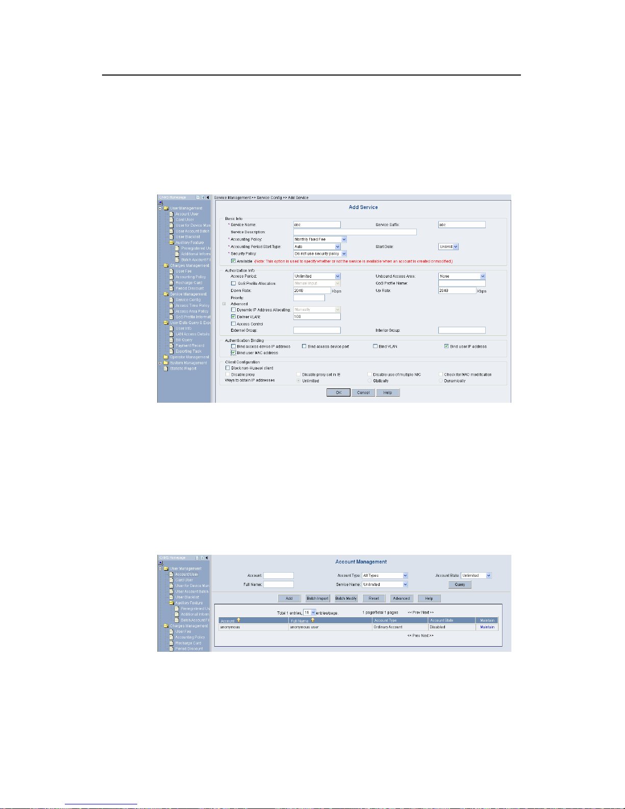
802.1x
H3C Low-End Ethernet Switches Configuration Examples
Chapter 3 Enterprise Network Access
Authentication Configuration Example
3-8
z Service Name: abc
z Service Suffix Name: abc
z Accounting Policy: Monthly Fixed Payment
z Upstream Rate Limitation: 2M (2048 Kbps)
z Downstream Rate Limitation: 2M (2048 Kbps)
z VLAN Assignment: VLAN 100
z Authentication Binding: Bind user IP address and bind user MAC address
Figure 3-8 Add Service
Click <OK>. A service type is added.
IV. Adding an account user
1) Enter the Account Management page.
Log in the CAMS configuration console. On the navigation tree, select [User
Management/Account User] to enter the [Account Management] page, as shown in
Figure 3-9.
Figure 3-9 Account Management
The list shows the created account users. You can maintain these account users.
2) Add an account user.
Page 58

802.1x
H3C Low-End Ethernet Switches Configuration Examples
Chapter 3 Enterprise Network Access
Authentication Configuration Example
3-9
Click <Add> to enter the [Add Acco unt] page and configure as follows:
z Account: info
z Password: info
z Full Name: Bruce
z Prepaid Money: 100 dollars
z Bind multiple IP address and MAC address: enable
z Online Limit: 1
z Max. Idle Time: 20 minutes
z Service Information: abc
Figure 3-10 Add Account
Click <OK>. An account user is ad ded.
V. Configuring the access device
1) Enter the System Configuration page.
Log in the CAMS configuration console. On the navigation tree, select [System
Management/System Configuration] to enter the [System Configuration] page, as
shown in
Figure 3-11.
Page 59

802.1x
H3C Low-End Ethernet Switches Configuration Examples
Chapter 3 Enterprise Network Access
Authentication Configuration Example
3-10
Figure 3-11 System Configuration
2) Click the Modify link for the Access Device item to enter the [Access Device
Configuration] page to modify access device configuration like IP address, shared
key, and authentication and accounting ports.
Figure 3-12 Access Device Configuration
VI. Adding configuration item
1) Click <Add> to enter the [Add Access Device] page and add configuration items,
as shown in
Figure 3-13.
Figure 3-13 Add Access Device
2) Click <OK>. The prompt page appears as shown in
Figure 3-14.
Page 60

802.1x
H3C Low-End Ethernet Switches Configuration Examples
Chapter 3 Enterprise Network Access
Authentication Configuration Example
3-11
Figure 3-14 Page prompting that system configuration is modified successfully
3) Return to the [System Configuration] page and click <Validate Now> to make the
configuration take effect immediately.
Figure 3-15 Validate Now on System Management page
3.3.3 Configuring the Supplicant System
You need to install an 802.1x client on the PC, which may be H3C’s 802.1x client, the
client shipped with Windows XP or other client from the third party. The following takes
H3C’s 802.1X as an example to introduce how to configure the supplicant system .
Page 61

802.1x
H3C Low-End Ethernet Switches Configuration Examples
Chapter 3 Enterprise Network Access
Authentication Configuration Example
3-12
I. Starting up H3C authentication client
Figure 3-16 H3C authentication client
II. Creating a connection
Right click the 802.1x Authentication icon and select [ Create an 802.1x connection], as
shown in
Figure 3-17.
Page 62

802.1x
H3C Low-End Ethernet Switches Configuration Examples
Chapter 3 Enterprise Network Access
Authentication Configuration Example
3-13
Figure 3-17 Create an 802.1x connection
III. Configuring connection attributes
Click <Next> to enter the [Set special properties] page:
Page 63

802.1x
H3C Low-End Ethernet Switches Configuration Examples
Chapter 3 Enterprise Network Access
Authentication Configuration Example
3-14
Figure 3-18 Set special properties
Keep default settings and click <OK>. The prompt page appears as shown in
Figure
3-19.
Page 64

802.1x
H3C Low-End Ethernet Switches Configuration Examples
Chapter 3 Enterprise Network Access
Authentication Configuration Example
3-15
Figure 3-19 Page prompting that a connection is created successfully
IV. Initiating the connection
Double click the info connection:
Figure 3-20 Connecting
The connection succeeds:
Page 65

802.1x
H3C Low-End Ethernet Switches Configuration Examples
Chapter 3 Enterprise Network Access
Authentication Configuration Example
3-16
Figure 3-21 Page prompting that the Authentication succeeds
3.3.4 Verifying Configuration
To verify that the configuration of Guest VLAN is taking effect, check that users can
access VLAN 10 before 802.1x authentication or the 802.1x authentication fails.
To verify that the dynamically assigned VLAN is taking effect, check that users can
access VLAN 100 after 802.1x authentication succeeds. At the same time, 802.1x
authentication cooperates with CAMS to complete accounting and real time monitoring.
To verify that the configuration of IP-to-MAC binding is taking effect, check that users
can be re-authenticated and access the Internet when the device reboot s abnormally. If
the configured IP-to-MAC binding is different from that on the CAMS, the user cannot
access the Internet.
3.3.5 Troubleshooting
I. Symptom: 802.1x authentication failed
Solution:
z Use the display dot1x command to verify 802.1x is enabled globally and on the
specified ports.
z Verify the username and password are set correctly.
z Verify the connection works well.
z Use the debugging dot1x packet command to verify the switch receives and
sends EAP and EAPoL packets normally.
Page 66

802.1x
H3C Low-End Ethernet Switches Configuration Examples
Chapter 3 Enterprise Network Access
Authentication Configuration Example
3-17
II. Symptom: Users can access network resources without 802.1x
authentication
z Use the display dot1x command to verify 802.1x is enabled globally and on the
specified ports.
z Use the display interface command to verify the statistics of incoming packets
are available for the specified port. 802.1x authentication applies only to incomi ng
packets, not outgoing packets.
Page 67

SSH
H3C Low-End Ethernet Switches Configuration Examples Table of Contents
i
Table of Contents
Chapter 1 SSH Overview .............................................................................................................. 1-1
1.1 Introduction to SSH............................................................................................................ 1-1
1.2 Support for SSH Functions................................................................................................ 1-1
1.3 SSH Configuration.............................................................................................................1-2
1.3.1 Configuring an SSH Server.....................................................................................1-2
1.3.2 Configuring an SSH Client...................................................................................... 1-2
1.3.3 Precautions .............................................................................................................1-2
Chapter 2 SSH Configuration Commands.................................................................................. 2-1
2.1 SSH Configuration Commands..........................................................................................2-1
2.2 Configuring an H3C Switch as an SSH Server..................................................................2-1
2.2.1 Configuration Procedure......................................................................................... 2-1
2.2.2 Configuration Commands .......................................................................................2-2
2.3 Configuring an H3C Switch as an SSH Client................................................................... 2-6
2.3.1 Configuration Procedure......................................................................................... 2-7
2.3.2 Configuration Commands .......................................................................................2-7
Chapter 3 SSH Configuration Example....................................................................................... 3-1
3.1 SSH Configuration Example.............................................................................................. 3-1
3.1.1 When the Switch Acts as the SSH Server and the Authentication Type is Password..... 3-1
3.1.2 When the Switch Acts as an SSH Server and the Authentication Type is RSA.....3-4
3.1.3 When the Switch Acts as an SSH Client and t he Authe ntication Typ e is Password.. 3-12
3.1.4 When the Switch Acts as an SSH Client and the Authentication Type is RSA .... 3-14
3.1.5 When the Switch Acts as an SSH Client and First-time authentication is not
Supported.......................................................................................................................
3-17
Page 68

SSH
H3C Low-End Ethernet Switches Configuration Examples Abstract
ii
SSH Configuration Example
Keywords: SSH, RSA
Abstract: This article introduces the application of SSH on the H3C low-end Ethernet
switches in real network environments, and then present s det ailed configurations of
the involved SSH client and Ethernet switches respectively.
Acronyms: SSH (Secure Shell), RSA (Rivest Shamir Adleman)
Page 69

SSH
H3C Low-End Ethernet Switches Configuration Examples Chapter 1 SSH Overview
1-1
Chapter 1 SSH Overview
1.1 Introduction to SSH
Secure Shell (SSH) is designed to provide secure remote login and other security
services in insecure network environments. When users remotely access the switch
across an insecure network, SSH will automatically encrypt data before transmission
and decrypt data after they reach the destination to guarantee information security and
protect switches from such attacks as plain-text password interception. In addition,
SSH provides powerful authentication to defend against the man-in-the-middle att acks.
SSH uses the client/server mode, by which the SSH server accepts the connection
requests from SSH clients and provides authentication. SSH client s can est ablish SSH
connections and log into the SSH server through the SSH connections.
SSH also provides other functions, such as compressing the data to be transmitted to
speed up the transmission speed, functioning as Telnet, and providing secure channels
for FTP, PoP and even PPP.
Note:
For details about SSH functions supported on different Ethernet switches, refer to
related user manuals.
1.2 Support for SSH Functions
Table 1-1 List of SSH functions supported on the H3C low-end Ethernet switches
Function
Model
SSH server SSH client
S3600-EI
z
z
S3600-SI
z
z
S5600
z
z
S5100
z
z
S3100
z
z
S3100-52P
z
z
Page 70

SSH
H3C Low-End Ethernet Switches Configuration Examples Chapter 1 SSH Overview
1-2
1.3 SSH Configuration
1.3.1 Configuring an SSH Server
I. For a H3C switch to be the SSH server
z Configure the protocols supported on user interfaces
z Create or destroy a RSA key pair
z Export a RSA key pair
z Create an SSH user and specify an authentication type
z Specify a service type for the SSH user
z Configure the SSH management function on the SSH server
z Configure a client public key on the SSH server
z Specify a public key for the SSH user
z Specify the source IP address or source interface of packets
II. For a non H3C device to be the SSH server
For such configuration, refer to the related user manual.
1.3.2 Configuring an SSH Client
I. Using SSH client software
There are many kinds of SSH client software, such as PuTTY and OpenSSH. You can
select one as required and refer to the attached manual for configuration.
II. Using an SSH2-capable switch
z Configure whether first-time authentication is supported
z Establish a connection between the SSH client and the SSH server
1.3.3 Precautions
z If you have configured a user interface to support the SSH protocol, you must
configure AAA authentication for the user interface by using the
authentication-mode scheme command to ensure successful login.
z Creating a RSA key pair on the SSH server is necessary for su ccessful SSH log in.
z For new SSH users to login successfully, you must specify an authentication type
for them.
Page 71

SSH
H3C Low-End Ethernet Switches Configuration Examples Chapter 2 SSH Configuration Commands
2-1
Chapter 2 SSH Configuration Commands
2.1 SSH Configuration Commands
To implement SSH, you need to configure the SSH client and the SSH server correctly.
The subsequent sections describe SSH configuration commands on the switch. For
more information, refer to the SSH Operation Manual.
2.2 Configuring an H3C Switch as an SSH Server
2.2.1 Configuration Procedure
Table 2-1 Configure the switch as an SSH server
Role
Common
configur
ation
Authenticatio
n type
Public key
configuration
Remarks
Password
authentication
—
For detailed
command, refer
to
Password
authentication.
Configure a
public key
manually:
copy the
public key
from the
client public
key file to
the SSH
server.
For detailed
commands, refer
to
Configuring
the client RSA
public key
manually .
SSH
server
For
detailed
command
, refer to
Common
configurat
ion.
RSA
authentication
Import a
public key:
import the
public key
from the
client public
file to the
SSH server
through
commands.
Associat
e the
client
public
key
saved
on the
SSH
server to
the SSH
client
For detailed
commands, refer
to
Importing the
client RSA public
key .
I. Precautions for authentication type configuration
The above table introduces the password authentication and RSA authentication
separately. In practice, you can combine the two authentication types.
Page 72

SSH
H3C Low-End Ethernet Switches Configuration Examples Chapter 2 SSH Configuration Commands
2-2
z Executing the ssh authentication-type default password-publickey command
or the ssh user authentication-type password-publickey command means that
users must not only pass the password authentication but also pass the RSA
authentication to login the SSH server.
z Executing the ssh authentication-type default all command or the ssh user
authentication-type all command means that users can login the SSH se rver as
long as they pass either the password or RSA authentication.
II. Public key configuration procedure and precautions
As shown inTable 2-1, you need to copy or import the public key from the client to the
server.
1) Manually configure the RSA public key
z When a switch acts as the SSH client, use the display rsa local-key-pair public
command to display the RSA public key after creating RSA key pair through the
corresponding commands.
z Manually copy the RSA public key to the SSH server. Thus, the SSH server has
the same public key as the SSH client, and can authenticate the SSH client when
the SSH client establishes a connection with it.
2) Import the RSA public key
z When a switch acts as the SSH server, use the SSH client software to generate an
RSA key pair, and then upload the RSA public key file to the SSH server through
FTP or TFTP.
z On the SSH server, import the public key from the public key file through
commands.
3) Precautions
When some SSH client software like PuTTY is used to generate an RSA key pair, you
can either manully configure the public key for the SSH server or import the public key
to the SSH server.
2.2.2 Configuration Commands
I. Common configuration
Table 2-2 Common configuration
Operation Command Remarks
Enter system view
system-view
—
Enter the view of one
or multiple user
interfaces
user-interface [ type-keyword ]
number [ ending-number ]
—
Page 73

SSH
H3C Low-End Ethernet Switches Configuration Examples Chapter 2 SSH Configuration Commands
2-3
Operation Command Remarks
Configure the
authentication mode
as scheme
authentication-mode scheme
[ command-authorization ]
Required
By default, the user
interface authentication
mode is password.
Specify the
supported protocol(s)
protocol inbound { all |ssh |
telnet }
Optional
By default, both Telnet
and SSH are supported.
Return to the system
view
quit —
Create an RSA key
pair
rsa local-key-pair create
Required
By default, no RSA key
pair is created.
Destroy the RSA key
pair
rsa local-key-pair destroy
Optional
Specify a service
type for the SSH user
ssh user username
service-type { stelnet | sftp |
all }
Optional
stelnet by default
Set SSH
authentication
timeout time
ssh server timeout seconds
Optional
By default, the timeout
time is 60 seconds.
Set SSH
authentication retry
times
ssh server
authentication-retries times
Optional
By default, the number of
retry times is 3.
Set RSA server key
update interval
ssh server rekey-interval
hours
Optional
By default, the system
does not update RSA
server keys.
Configure SSH
server to be
compatible with
SSH1.x clients
ssh server compatible-ssh1x
enable
Optional
By default, SSH server is
compatible with SSH1.x
clients.
Specify a source IP
address for the SSH
server
ssh-server source-ip
ip-address
Optional
Specify a source
interface for the SSH
server
ssh-server source-interface
interface-type
interface-number
Optional
Page 74

SSH
H3C Low-End Ethernet Switches Configuration Examples Chapter 2 SSH Configuration Commands
2-4
II. Password authentication configuration
Table 2-3 Configure password authentication
Operation Command Description
ssh
authenticatio
n-type
default
password
Specify the
default
authentication
type for all
SSH users
ssh user
username
Create an SSH User
and specify an
authentication type
Create an
SSH user,
and specify an
authentication
type for the
user
ssh user
username
authenticatio
n-type
password
Use either command.
By default, no SSH user
is created and no
authentication type is
specified.
Note that: If both
commands are used and
different authentication
types are specified, the
authentication type
specified with the ssh
user
authentication-type
command takes
precedence.
Note:
For common configuration commands, refer toTable 2-2.
III. Configuring the client RSA public key manually
Table 2-4 Configure the client RSA public key manually
Operation Command Description
ssh
authenticatio
n-type
default rsa
Specify the
default
authentication
type for all
SSH users
ssh user
username
Create an SSH user
and specify an
authentication type
Create an
SSH user,
and specify an
authentication
type for it
ssh user
username
authenticatio
n-typ rsa
Use either command.
By default, no SSH user
is created and no
authentication type is
specified.
Note that: If both
commands are used and
different authentication
types are specified, the
authentication type
specified with the ssh
user
authentication-type
command takes
precedence.
Enter public key view
rsa peer-public-key keyname
Required
Enter public key edit
view
public-key-code begin —
Page 75

SSH
H3C Low-End Ethernet Switches Configuration Examples Chapter 2 SSH Configuration Commands
2-5
Operation Command Description
Configure the client
RSA public key
Enter the content of the RSA
public key
The content must be a
hexadecimal string that
is generated randomly by
the SSH-supported client
software and coded
compliant to PKCS.
Spaces and carriage
returns are allowed
between characters.
Return from public
key code view to
public key view
public-key-code end
When you exit public key
code view, the system
automatically saves the
public key.
Return from public
key view to system
view
peer-public-key end —
Assign a public key to
an SSH user
ssh user username assign
rsa-key keyname
Required
If you issue this
command multiple times,
the last command
overrides the previous
ones
Note:
For general configuration commands, refer toTable 2-2.
IV. Importing the client RSA public key
Table 2-5 Import the client RSA public key
Operation Command Description
ssh
authenticatio
n-type
default rsa
Specify the
default
authentication
type for all
SSH users
ssh user
username
Create an SSH user
and specify an
authentication type
Create an
SSH user,
and specify an
authentication
type for it
ssh user
username
authenticatio
n-type rsa
Use either command.
By default, no SSH user
is created and no
authentication type is
specified.
Note that: If both
commands are used and
different authentication
types are specified, the
authentication type
specified with the ssh
user
authentication-type
command takes
precedence.
Page 76

SSH
H3C Low-End Ethernet Switches Configuration Examples Chapter 2 SSH Configuration Commands
2-6
Operation Command Description
Import the client RSA
public key from the
specified public key
file
rsa peer-public-key keyname
import sshkey filename
Required
Assign a public key to
an SSH user
ssh user username assign
rsa-key keyname
Required
If you issue this
command multiple times,
the last command
overrides the previous
ones
Note:
For general configuration commands, refer toTable 2-2.
2.3 Configuring an H3C Switch as an SSH Client
When the device connects to the SSH server as an SSH client, you can configure
whether the device supports first-time authentication.
z First-time authentication means that when the SSH client accesses the server for
the first time and is not configured with the server host public key, the user can
continue accessing the server, and will save the host public key on the client for
use in subsequent authentications.
z When first-time authentication is not supported, a client, if not configured with the
server host public key, will be denied of access to the server. To access the server,
a user must configure in advance the server host public key locally and specify the
public key name for authentication.
Page 77

SSH
H3C Low-End Ethernet Switches Configuration Examples Chapter 2 SSH Configuration Commands
2-7
2.3.1 Configuration Procedure
Table 2-6 Configure the switch as an SSH client
Role
Common
configur
ation
First-time
authentic
ation
support
Public key
configuration
Access
the SSH
server
Remarks
Yes
—
Refer to
Enabling
first-time
authentic
ation.
SSH
Client
Refer to
Common
configura
tion.
No
Configure
a public
key
manually:
copy the
server
public key
from the
public key
file to the
SSH client
Specify
the host
public key
of the
SSH
server to
be
connected
Establish
a
connecti
on
between
the SSH
client and
the SSH
server
Refer to
Disabling
first-time
authentic
ation and
manually
configurin
g the
server
public
key.
As shown in
Table 2-6, you need to configure the server public key to the client in the
case that the SSH client does not support first-time authentication.
2) Manually configure the RSA public key
z On the SSH server, use the display rsa local-key-pair public command to
display the RSA public key.
z Manually copy the public key to the SSH client. Thus, the SSH client has the same
public key as the SSH server, and can authenticate the SSH server using the
public key when establishing a connection with the SSH server.
2.3.2 Configuration Commands
I. Common configuration
Table 2-7 Common configuration
Operation Command Description
Enter system view
system-view
—
Specify a source IP
address for the SSH
client
ssh2 source-ip ip-address
Optional
Page 78

SSH
H3C Low-End Ethernet Switches Configuration Examples Chapter 2 SSH Configuration Commands
2-8
Operation Command Description
Specify a source
interface for the SSH
client
ssh2 source-interface
interface-type interface-number
Optional
II. Enabling first-time authentication
Table 2-8 Enable first-time authentication
Operation Command Description
Enter system view
system-view
—
Enable first-time
authentication
ssh client first-time enable
Optional
Enabled by default
Establish a connection
with the SSH server
ssh2 { host-ip | host-name }
[ port-num ] [ prefer_kex
{ dh_group1 |
dh_exchange_group } |
prefer_ctos_cipher { des |
aes128 } | prefer_stoc_cipher
{ des | aes128 } |
prefer_ctos_hmac { sha1 |
sha1_96 | md5 | md5_96 } |
prefer_stoc_hmac { sha1 |
sha1_96 | md5 | md5_96 } ] *
Required
In this command,
you can also
specify the
preferred key
exchange
algorithm,
encryption
algorithms and
HMAC algorithms
between the server
and client.
III. Disabling first-time authentication and manually configuring the server
public key
Table 2-9 Disable first-time authentication and manually configure the server public
key
Operation Command Description
Enter system view
system-view
—
Disable first-time
authentication
undo ssh client first-time
Required
Enabled by default
Enter public key view
rsa peer-public-key
keyname
Required
Enter public key edit
view
public-key-code begin —
Page 79

SSH
H3C Low-End Ethernet Switches Configuration Examples Chapter 2 SSH Configuration Commands
2-9
Operation Command Description
Configure server
public key
Enter the content of the public
key
When you input the key
data, spaces are allowed
between the characters
you input (because the
system can remove the
spaces automatically);
you can also press
<Enter> to continue your
input at the next line. But
the key you input should
be a hexadecimal digit
string coded in the public
key format.
Return to public key
view from public key
edit view
public-key-code end
When you exit public key
code view, the system
automatically saves the
public key
Exit public key view
and return to system
view
peer-public-key end —
Specify the host key
name of the server
ssh client { server-ip |
server-name } assign
rsa-key keyname
Optional
Required when the SSH
client does not support
first-time authentication
You need to copy the
server public key to the
SSH client before
performing this
configuration.
Start the client to
establish a connection
with an SSH server
ssh2 { host-ip | host-name }
[ port-num ] [ prefer_kex
{ dh_group1 |
dh_exchange_group } |
prefer_ctos_cipher { des |
aes128 } |
prefer_stoc_cipher { des |
aes128 } |
prefer_ctos_hmac { sha1 |
sha1_96 | md5 | md5_96 } |
prefer_stoc_hmac { sha1 |
sha1_96 | md5 | md5_96 } ] *
Required
In this command, you can
also specify the preferred
key exchange algorithm,
encryption algorithms
and HMAC algorithms
between the server and
client.
Page 80

SSH
H3C Low-End Ethernet Switches Configuration Examples Chapter 3 SSH Configuration Example
3-1
Chapter 3 SSH Configuration Example
Note:
The S3600 software version in this configuration example is Release 1510.
3.1 SSH Configuration Example
3.1.1 When the Switch Acts as the SSH Server and the Authentication Type is
Password
I. Network requirements
As shown inFigure 3-1, establish an SSH connection between the host (SSH Client)
and the switch (SSH Server) for secure data exchange. The host runs SSH2.0 client
software. Password authentication is required.
II. Network diagram
Figure 3-1 Network diagram of SSH server configuration using password
authentication
III. Configuration procedure
1) Configure the SSH server
# Create a VLAN interface on the switch and assign an IP address, which the SSH
client will use as the destination for SSH connection.
<H3C> system-view
[H3C] interface vlan-interface 1
[H3C-Vlan-interface1] ip address 192.168.0.1 255.255.255.0
[H3C-Vlan-interface1] quit
# Generate RSA key pairs.
[H3C] rsa local-key-pair create
# Set the authentication mode for the user interfaces to AAA.
Page 81

SSH
H3C Low-End Ethernet Switches Configuration Examples Chapter 3 SSH Configuration Example
3-2
[H3C] user-interface vty 0 4
[H3C-ui-vty0-4] authentication-mode scheme
# Enable the user interfaces to support SSH.
[H3C-ui-vty0-4] protocol inbound ssh
[H3C-ui-vty0-4] quit
# Create local client “client001”, and set the authentication password to “abc”, protocol
type to SSH, and command privilege level to 3 for the client.
[H3C] local-user client001
[H3C-luser-client001] password simple abc
[H3C-luser-client001] service-type ssh level 3
[H3C-luser-client001] quit
# Specify the authentication method of user client001 as password.
[H3C] ssh user client001 authentication-type password
2) Configure the SSH client
# Configure an IP address (192.168.0.2 in this case) for the SSH client. This IP address
and that of the VLAN interface on the switch must be in the same network segment.
# Configure the SSH client software to establish a connection to the SSH serve r.
Take SSH client software “Putty” (version 0.58) as an example:
z Run PuTTY.exe to enter the following configuration interface.
Figure 3-2 SSH client configuration interface
Page 82

SSH
H3C Low-End Ethernet Switches Configuration Examples Chapter 3 SSH Configuration Example
3-3
In the Host Name (or IP address) text box, enter the IP address of the SSH server.
z From the category on the left pane of the window, select SSH under Connection.
The window as shown in
Figure 3-3 appears.
Figure 3-3 SSH client configuration interface 2
Under Protocol options, select 2 from Preferred SSH protocol version.
z As shown inFigure 3-4, click Open to enter the following interface. If the
connection is normal, you will be prompted to enter the user name “client001” and
password “abc”. Once authentication succeeds, you will log onto the server.
Page 83

SSH
H3C Low-End Ethernet Switches Configuration Examples Chapter 3 SSH Configuration Example
3-4
Figure 3-4 SSH client interface
3.1.2 When the Switch Acts as an SSH Server and the Authentication Type is
RSA
I. Network requirements
As shown inFigure 3-5, establish an SSH connection between the host (SSH client) and
the switch (SSH Server) for secure data exchange. The host runs SSH2.0 client
software. RSA authentication is required.
II. Network diagram
Figure 3-5 Network diagram of SSH server configuration
III. Configuration procedure
1) Configure the SSH server
# Create a VLAN interface on the switch and assign an IP address, which the SSH
client will use as the destination for SSH connection.
<H3C> system-view
[H3C] interface vlan-interface 1
Page 84

SSH
H3C Low-End Ethernet Switches Configuration Examples Chapter 3 SSH Configuration Example
3-5
[H3C-Vlan-interface1] ip address 192.168.0.1 255.255.255.0
[H3C-Vlan-interface1] quit
# Generate RSA key pairs.
[H3C] rsa local-key-pair create
# Set the authentication mode for the user interfaces to AAA.
[H3C] user-interface vty 0 4
[H3C-ui-vty0-4] authentication-mode scheme
# Enable the user interfaces to support SSH.
[H3C-ui-vty0-4] protocol inbound ssh
# Set the client’s command privilege level to 3
[H3C-ui-vty0-4] user privilege level 3
[H3C-ui-vty0-4] quit
# Configure the authentication type of the SSH client named client 001 as RSA.
[H3C] ssh user client001 authentication-type rsa
Note:
Before performing the following steps, you must generate an RSA public key pair
(using the client software) on the client, save the key pair in a file named public, and
then upload the file to the SSH server through FTP or TFTP. For details, refer to
Configuring the SSH Client.
# Import the client’s public key named “Switch001” from file “public”.
[H3C] rsa peer-public-key Switch001 import sshkey public
# Assign the public key “Switch001” to client “client001”.
[H3C] ssh user client001 assign rsa-key Switch001
2) Configure the SSH client
# Generate an RSA key pair, taking PuTTYGen as an example.
z Run PuTTYGen.exe, choose SSH2(RSA) and click Generate.
Page 85

SSH
H3C Low-End Ethernet Switches Configuration Examples Chapter 3 SSH Configuration Example
3-6
Figure 3-6 Generate a client key pair (1)
Note:
While generating the key pair, you must move the mouse continuously and keep the
mouse off the green process bar shown in
Figure 3-6. Otherwise, the process bar stops
moving and the key pair generating process is stopped.
Page 86

SSH
H3C Low-End Ethernet Switches Configuration Examples Chapter 3 SSH Configuration Example
3-7
Figure 3-7 Generate a client key pair (2)
After the key pair is generated, click Save public key and enter the name of the file for
saving the public key (“public” in this case).
Page 87

SSH
H3C Low-End Ethernet Switches Configuration Examples Chapter 3 SSH Configuration Example
3-8
Figure 3-8 Generate a client key pair (3)
Likewise, to save the private key, click Save private key. A warning window pops up to
prompt you whether to save the private key without any protection. Click Yes and enter
the name of the file for saving the private key (“private.ppk” in this case).
Figure 3-9 Generate a client key pair (4)
Note:
After a public key pair is generated, you need to upload the pubic key file to the server
through FTP or TFTP, and complete the server end configuration before you continue
to configure the client.
Page 88

SSH
H3C Low-End Ethernet Switches Configuration Examples Chapter 3 SSH Configuration Example
3-9
# Establish a connection with the SSH server.
The following takes the SSH client software Putty (version 0.58) as an example.
z Launch PuTTY.exe to enter the following interface.
Figure 3-10 SSH client configuration interface 1
In the Host Name (or IP address) text box, enter the IP address of the server.
z From the category on the left pane of the window, select SSH under Connection.
The window as shown in
Figure 3-11appears.
Page 89

SSH
H3C Low-End Ethernet Switches Configuration Examples Chapter 3 SSH Configuration Example
3-10
Figure 3-11 SSH client configuration interface 2
Under Protocol options, select 2 from Preferred SSH protocol version.
z Select Connection/SSH/Auth. The following window appears.
Page 90

SSH
H3C Low-End Ethernet Switches Configuration Examples Chapter 3 SSH Configuration Example
3-11
Figure 3-12 SSH client configuration interface (2)
Click Bro wse… to bring up the file selection window , navigate to the private key file and
click OK.
z From the window shown inFigure 3-12, click Open. The following SSH client
interface appears. If the connection is normal, you will be prompted to enter the
username and password, as shown in
Figure 3-13.
Page 91

SSH
H3C Low-End Ethernet Switches Configuration Examples Chapter 3 SSH Configuration Example
3-12
Figure 3-13 SSH client interface
3.1.3 When the Switch Acts as an SSH Client and the Authentication Type is
Password
I. Network requirements
As shown inFigure 3-14, establish an SSH connection between Switch A (SSH Client)
and Switch B (SSH Server) for secure data exchange. The user name for login is
client001 and the SSH server’s IP address is 10.165.87.136. Password authentication
is required.
II. Network diagram
Figure 3-14 Network diagram of SSH client configuration when using password
authentication
III. Configuration procedure
1) Configure Switch B
# Create a VLAN interface on the switch and assign an IP address, which the SSH
client will use as the destination for SSH connection.
Page 92

SSH
H3C Low-End Ethernet Switches Configuration Examples Chapter 3 SSH Configuration Example
3-13
<H3C> system-view
[H3C] interface vlan-interface 1
[H3C-Vlan-interface1] ip address 10.165.87.136 255.255.255.0
[H3C-Vlan-interface1] quit
# Generate RSA key pairs.
[H3C] rsa local-key-pair create
# Set the authentication mode for the user interfaces to AAA.
[H3C] user-interface vty 0 4
[H3C-ui-vty0-4] authentication-mode scheme
# Enable the user interfaces to support SSH.
[H3C-ui-vty0-4] protocol inbound ssh
[H3C-ui-vty0-4] quit
# Create local user “client001”, and set the authentication password to abc, the login
protocol to SSH, and user command privilege level to 3.
[H3C] local-user client001
[H3C-luser-client001] password simple abc
[H3C-luser-client001] service-type ssh level 3
[H3C-luser-client001] quit
# Configure the authentication type of user client001 as password.
[H3C] ssh user client001 authentication-type password
2) Configure Switch A
# Create a VLAN interface on the switch and assign an IP address, which serves as the
SSH client’s address in an SSH connection.
<H3C> system-view
[H3C] interface vlan-interface 1
[H3C-Vlan-interface1] ip address 10.165.87.137 255.255.255.0
[H3C-Vlan-interface1] quit
# Establish a connection to the server 10.165.87.136.
[H3C] ssh2 10.165.87.136
Username: client001
Trying 10.165.87.136 ...
Press CTRL+K to abort
Connected to 10.165.87.136 ...
The Server is not authenticated. Do you continue to access it?(Y/N):y
Do you want to save the server's public key?(Y/N):n
Enter password:
*************************************************************************
Page 93

SSH
H3C Low-End Ethernet Switches Configuration Examples Chapter 3 SSH Configuration Example
3-14
* Copyright(c) 2004-2006 Hangzhou H3C Technologies Co., Ltd. *
* Without the owner's prior written consent, *
* no decompiling or reverse-engineering shall be allowed. *
*************************************************************************
<H3C>
3.1.4 When the Switch Acts as an SSH Client and the Authentication Type is
RSA
I. Network requirements
As shown inFigure 3-15, establish an SSH connection between Switch A (SSH Client)
and Switch B (SSH Server) for secure data exchange. The user name is client001 and
the SSH server’s IP address is 10.165.87.136. RSA authentication is required.
II. Network diagram
Figure 3-15 Network diagram of SSH client configuration when using publickey
authentication
III. Configuration procedure
1) Configure Switch B
# Create a VLAN interface on the switch and assign an IP address, which the SSH
client will use as the destination for SSH connection.
<H3C> system-view
[H3C] interface vlan-interface 1
[H3C-Vlan-interface1] ip address 10.165.87.136 255.255.255.0
[H3C-Vlan-interface1] quit
# Generate RSA key pair.
[H3C] rsa local-key-pair create
# Set the authentication mode for the user interfaces to AAA.
[H3C] user-interface vty 0 4
[H3C-ui-vty0-4] authentication-mode scheme
# Enable the user interfaces to support SSH.
[H3C-ui-vty0-4] protocol inbound ssh
# Set the user command privilege level to 3.
Page 94

SSH
H3C Low-End Ethernet Switches Configuration Examples Chapter 3 SSH Configuration Example
3-15
[H3C-ui-vty0-4] user privilege level 3
[H3C-ui-vty0-4] quit
# Specify the authentication type of user client001 as RSA.
[H3C] ssh user client001 authentication-type rsa
Note:
Before proceeding with the following steps, you need to generate an RSA key pair on
the client, and manually configure the RSA public key for the SSH server. For detailed
information, refer to SSH client configuration.
# Configure the public key of the SSH client on the SSH server, and specify the public
key name as Switch001..
[H3C] rsa peer-public-key Switch001
RSA public key view: return to System View with "peer-public-key end".
[H3C-rsa-public-key] public-key-code begin
RSA key code view: return to last view with "public-key-code end".
[H3C-rsa-key-code] 3047
[H3C-rsa-key-code] 0240
[H3C-rsa-key-code] C8969B5A 132440F4 0BDB4E5E 40308747 804F608B
[H3C-rsa-key-code] 349EBD6A B0C75CDF 8B84DBE7 D5E2C4F8 AED72834
[H3C-rsa-key-code] 74D3404A 0B14363D D709CC63 68C8CE00 57C0EE6B
[H3C-rsa-key-code] 074C0CA9
[H3C-rsa-key-code] 0203
[H3C-rsa-key-code] 010001
[H3C-rsa-key-code] public-key-code end
[H3C-rsa-public-key] peer-public-key end
[H3C]
# Assign the public key Switch001 to user client001.
[H3C] ssh user client001 assign rsa-key Switch001
2) Configure Switch A
# Create a VLAN interface on the switch and assign an IP address, which serves as the
SSH client’s address in an SSH connection.
<H3C> system-view
[H3C] interface vlan-interface 1
[H3C-Vlan-interface1] ip address 10.165.87.137 255.255.255.0
[H3C-Vlan-interface1] quit
# Generate a RSA key pair
[H3C] rsa local-key-pair create
Page 95

SSH
H3C Low-End Ethernet Switches Configuration Examples Chapter 3 SSH Configuration Example
3-16
# Display the RSA public key on the client.
<H3C> display rsa local-key-pair public
=====================================================
Time of Key pair created: 05:15:04 2006/12/08
Key name: H3C_Host
Key type: RSA encryption Key
=====================================================
Key code:
3047
0240
C8969B5A 132440F4 0BDB4E5E 40308747 804F608B
349EBD6A B0C75CDF 8B84DBE7 D5E2C4F8 AED72834
74D3404A 0B14363D D709CC63 68C8CE00 57C0EE6B
074C0CA9
0203
010001
<Omitted>
Note:
After generating an RSA key pair on the client, you need to configure the RSA public
key for the SSH server and finish the SSH server configuration before continuing to
configure the SSH client.
# Establish an SSH connection to the server 10.165.87.136.
[H3C] ssh2 10.165.87.136
Username: client001
Trying 10.165.87.136 ...
Press CTRL+K to abort
Connected to 10.165.87.136 ...
The Server is not authenticated. Do you continue to access it?(Y/N):y
Do you want to save the server's public key?(Y/N):n
*************************************************************************
* Copyright(c) 2004-2006 Hangzhou H3C Technologies Co., Ltd. *
* Without the owner's prior written consent, *
* no decompiling or reverse-engineering shall be allowed. *
*************************************************************************
Page 96

SSH
H3C Low-End Ethernet Switches Configuration Examples Chapter 3 SSH Configuration Example
3-17
<H3C>
3.1.5 When the Switch Acts as an SSH Client and First-time authentication is
not Supported
I. Network requirements
As shown inFigure 3-16, establish an SSH connection between Switch A (SSH Client)
and Switch B (SSH Server) for secure data exchange. The user name is client001 and
the SSH server’s IP address is 10.165.87.136. The RSA authentication mode is used
to enhance security.
II. Network diagram
Figure 3-16 Network diagram of SSH client configuration
III. Configuration procedure
1) Configure Switch B
# Create a VLAN interface on the switch and assign an IP address for it to serve as the
destination of the client.
<H3C> system-view
[H3C] interface vlan-interface 1
[H3C-Vlan-interface1] ip address 10.165.87.136 255.255.255.0
[H3C-Vlan-interface1] quit
# Generate RSA key pairs.
[H3C] rsa local-key-pair create
# Set AAA authentication on user interfaces.
[H3C] user-interface vty 0 4
[H3C-ui-vty0-4] authentication-mode scheme
# Configure the user interfaces to support SSH.
[H3C-ui-vty0-4] protocol inbound ssh
# Set the user command privilege level to 3.
[H3C-ui-vty0-4] user privilege level 3
[H3C-ui-vty0-4] quit
Page 97

SSH
H3C Low-End Ethernet Switches Configuration Examples Chapter 3 SSH Configuration Example
3-18
# Specify the authentication type for user client001 a s RSA.
[H3C] ssh user client001 authentication-type rsa
Note:
Before proceeding with the following steps, you need to generate an RSA key pair on
the client, and manually configure the RSA public key for the SSH server. For detailed
information, refer to SSH client configuration.
# Configure the public key of the SSH client on the SSH server, and specify the public
key name as Switch001
[H3C] rsa peer-public-key Switch001
RSA public key view: return to System View with "peer-public-key end".
[H3C-rsa-public-key] public-key-code begin
RSA key code view: return to last view with "public-key-code end".
[H3C-rsa-key-code] 3047
[H3C-rsa-key-code] 0240
[H3C-rsa-key-code] C8969B5A 132440F4 0BDB4E5E 40308747 804F608B
[H3C-rsa-key-code] 349EBD6A B0C75CDF 8B84DBE7 D5E2C4F8 AED72834
[H3C-rsa-key-code] 74D3404A 0B14363D D709CC63 68C8CE00 57C0EE6B
[H3C-rsa-key-code] 074C0CA9
[H3C-rsa-key-code] 0203
[H3C-rsa-key-code] 010001
[H3C-rsa-key-code] public-key-code end
[H3C-rsa-public-key] peer-public-key end
[H3C]
# Assign public key Switch001 to user client001
[H3C] ssh user client001 assign rsa-key Switch001
Note:
If first-time authentication is disabled on the device, it is necessary to configure on the
SSH client the RSA public key of the SSH server.
# Display the RSA public key on the server.
[H3C] display rsa local-key-pair public
=====================================================
Page 98

SSH
H3C Low-End Ethernet Switches Configuration Examples Chapter 3 SSH Configuration Example
3-19
Time of Key pair created: 09:04:41 2000/04/04
Key name: H3C_Host
Key type: RSA encryption Key
=====================================================
Key code:
308188
028180
C9330FFD 2E2A606F 3BFD5554 8DACDFB8 4D754E86
FC2D15E8 1996422A 0F6A2A6A A94A207E 1E25F3F9
E0EA01A2 4E0F2FF7 B1D31505 39F02333 E443EE74
5C3615C3 E5B3DC91 D41900F0 2AE8B301 E55B1420
024ECF2C 28A6A454 C27449E0 46EB1EAF 8A918D33
BAF53AF3 63B1FB17 F01E4933 00BE2EEA A272CD78
C289B7DD 2BE0F7AD
0203
010001
<Omitted>
2) Configure Switch A
# Create a VLAN interface on the switch and assign an IP address, which serves as the
SSH client’s address in an SSH connection.
<H3C> system-view
[H3C] interface vlan-interface 1
[H3C-Vlan-interface1] ip address 10.165.87.137 255.255.255.0
[H3C-Vlan-interface1] quit
# Generate a RSA key pair
[H3C] rsa local-key-pair create
# Export the generated RSA key pair to a file named Switch001.
<H3C> display rsa local-key-pair public
=====================================================
Time of Key pair created: 05:15:04 2006/12/08
Key name: H3C_Host
Key type: RSA encryption Key
=====================================================
Key code:
3047
0240
C8969B5A 132440F4 0BDB4E5E 40308747 804F608B
349EBD6A B0C75CDF 8B84DBE7 D5E2C4F8 AED72834
74D3404A 0B14363D D709CC63 68C8CE00 57C0EE6B
074C0CA9
Page 99

SSH
H3C Low-End Ethernet Switches Configuration Examples Chapter 3 SSH Configuration Example
3-20
0203
010001
<Omitted>
Note:
After the SSH client generates an RSA key pair, it is necessary to configure the RSA
public key for the SSH server and finish the SSH server configuration before continuing
to configure the SSH client.
# Disable first-time authentication on the device.
[H3C] undo ssh client first-time
Note:
If first-time authentication is disabled on the device, it is necessary to configure on the
SSH client the RSA public key of the SSH server.
# Configure the public key of the SSH server on the SSH client, and specify the public
key name as Switch002.
[H3C] rsa peer-public-key Switch002
RSA public key view: return to System View with "peer-public-key end".
[H3C-rsa-public-key] public-key-code begin
RSA key code view: return to last view with "public-key-code end".
[H3C-rsa-key-code] 308188
[H3C-rsa-key-code] 028180
[H3C-rsa-key-code] C9330FFD 2E2A606F 3BFD5554 8DACDFB8 4D754E86
[H3C-rsa-key-code] FC2D15E8 1996422A 0F6A2A6A A94A207E 1E25F3F9
[H3C-rsa-key-code] E0EA01A2 4E0F2FF7 B1D31505 39F02333 E443EE74
[H3C-rsa-key-code] 5C3615C3 E5B3DC91 D41900F0 2AE8B301 E55B1420
[H3C-rsa-key-code] 024ECF2C 28A6A454 C27449E0 46EB1EAF 8A918D33
[H3C-rsa-key-code] BAF53AF3 63B1FB17 F01E4933 00BE2EEA A272CD78
[H3C-rsa-key-code] C289B7DD 2BE0F7AD
[H3C-rsa-key-code] 0203
[H3C-rsa-key-code] 010001
[H3C-rsa-key-code] public-key-code end
[H3C-rsa-public-key] peer-public-key end
[H3C]
Page 100

SSH
H3C Low-End Ethernet Switches Configuration Examples Chapter 3 SSH Configuration Example
3-21
# Specify the host public key pair name of the server.
[H3C] ssh client 10.165.87.136 assign rsa-key Switch002
# Establish the SSH connection to server 10.165.87.136.
[H3C] ssh2 10.165.87.136
Username: client001
Trying 10.165.87.136 ...
Press CTRL+K to abort
Connected to 10.165.87.136 ...
*************************************************************************
* Copyright(c) 2004-2006 Hangzhou H3C Technologies Co., Ltd. *
* Without the owner's prior written consent, *
* no decompiling or reverse-engineering shall be allowed. *
*************************************************************************
<H3C>
 Loading...