

Page 1
Tool list 工具参考
The installation tools are not provided with the LB device. Prepare them
yourself.
设备不随机提供安装工具,请用户根据实际安装需求自备安装工具。
Airflow of the LB device 设备的风道设计
Make sure the air inlet and outlet vents are not blocked and the installation
site has a good ventilation system.
请确保设备的进、出风孔不被遮挡,并将设备安装在具有良好通风散热系
统的环境中。
Flat-blade
screwdriver
一字螺丝刀
Wire crimper
压线钳
Phillips
screwdriver
十字螺丝刀
Diagonal pliers
斜口钳
Needle-nose
pliers
尖嘴钳
ESD-preventive wrist strap
防静电腕带
Wire-stripping
pliers
剥线钳
Marker
记号笔
Installation accessories 安装附件介绍
Cage nut
(user supplied)
浮动螺母(用户自备)
Mounting brackets
and cable management
brackets (required)
挂耳(标配)
M6 screw
(user supplied)
M6 螺钉(用户自备)
Rubber pads
(required)
胶垫贴(标配)
Removable cable tie
(user supplied)
可拆卸式扎带(用户自备)
Grounding cable
(required)
地线(标配)
Wear an ESD-preventive wrist strap, and make sure the wrist strap makes
good skin contact and is well grounded.
操作者需佩戴防静电腕带,确保防静电腕带与皮肤良好接触,并确认防静电
腕带已经良好接地。
1
M4 countersunk-head
screw (required)
M4沉头螺钉(标配)
Bail latch(required)
电源卡钩(标配)
Left-to-right airflow aisle.
设备采用左进右出的风道设计
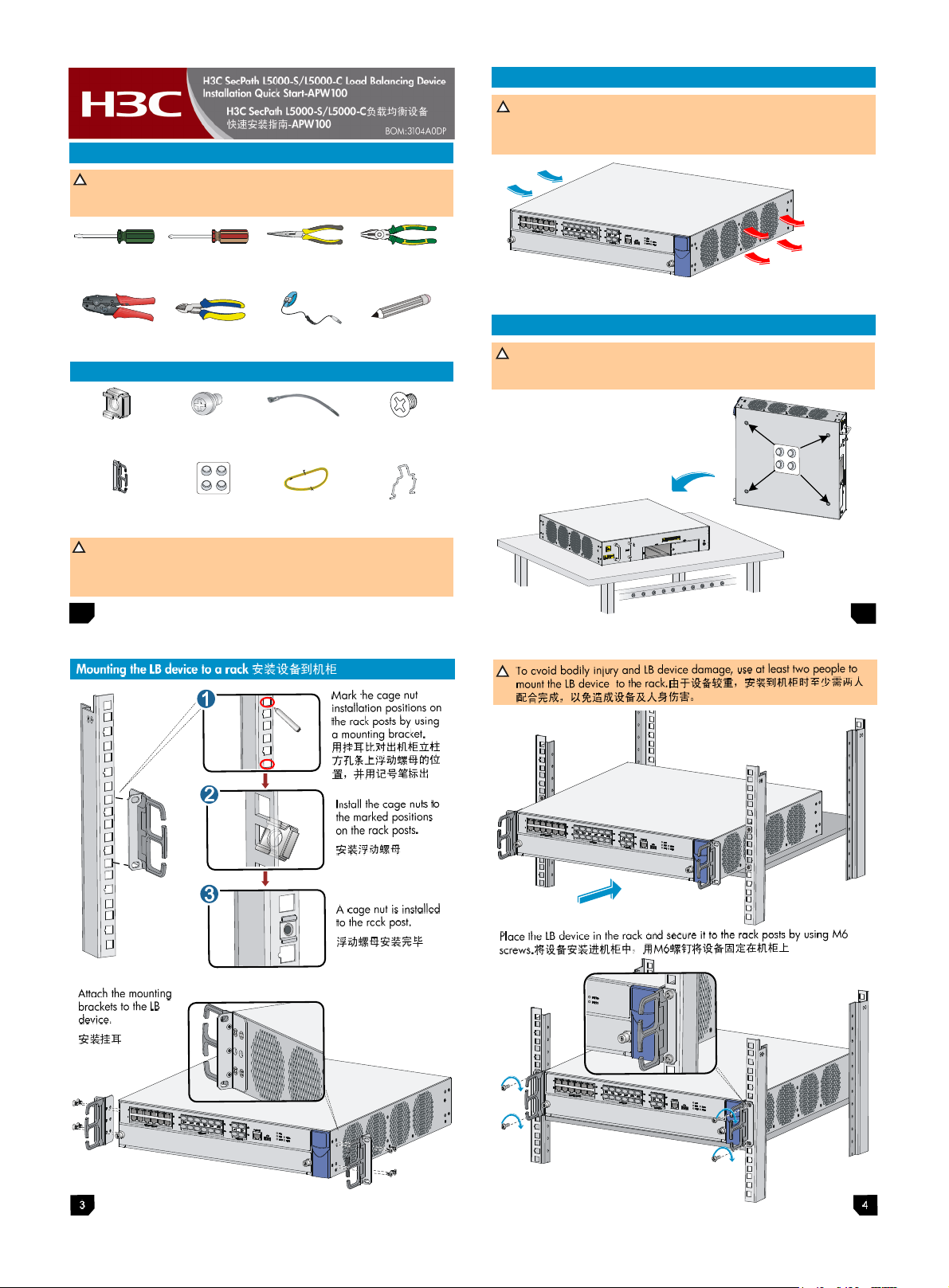
Mounting the LB device to a workbench 安装设备到工作台
Make sure the workbench is sturdy and correctly grounded.
Do not place heavy objects on the LB device.
保证工作台的平稳与良好接地,并且不要在设备上放置重物。
Attach the rubber feet to the four
round holes in the chassis bottom.
Place the LB device with upside up
on the workbench. 粘贴胶垫到设备
底部,将带胶垫贴的设备平放到工
作台上
2
Page 2
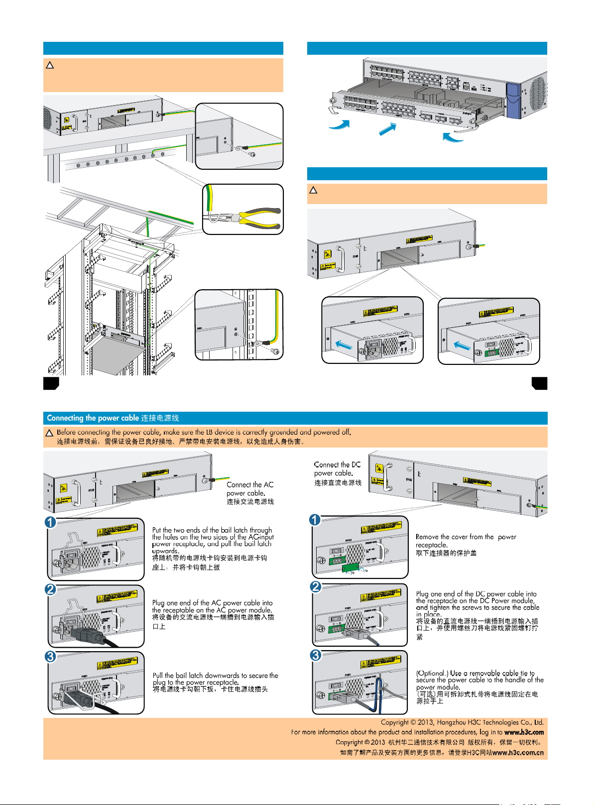
Connecting the grounding cable 连接保护地线
Correctly connecting the grounding cable is crucial to lightning protection
and EMI protection. To guarantee the grounding effect, use the grounding
cable provided with the LB device. 设备地线的正确连接是设备防雷、防干
扰的重要保障,请使用设备随机提供的保护地线正确接地。
+
+
Installing an interface card 安装接口板
1. Remove the filler panel from the interface card slot.拆卸接 口板槽位假面板
2. Insert the interface card into the slot.插入接口板
3. Use the Phillips screwdriver to tighten the captive screws.用十字螺丝刀拧紧松不脱螺丝
Installing a power module 安装电源模块
Do not install AC and DC power modules on the same LB device.
设备不支持直流和交流电源模块混插。
1. Remove the filler
panel from the power
module slot.拆卸电源
槽位假面板
2. Insert the AC or DC
power module.插入
AC/DC电源模块
3. Tighten the captive
screws to secure the
power module in
place.旋紧固定螺钉
AC power module
5
交流电源模块
DC power module
直流电源模块
6
Page 3

服务器负载均衡基本配置
操作
进入系统视图
创建实服务器组,并进入实服务器组视图
配置
配置实服务器组的调度算法 缺省情况下,实服务器组的调度算法为加权轮转算法
实服
务器
配置实服务器组中参与调度的实服务
组
器数量限制
配置实服务器组的可用条件
配置实服务器组的故障处理方式
创建实服务器,并进入实服务器视图
配置
配置实服务器的VSIP
实服
务器
配置实服务器的端口号
配置实服务器的权值 weight-value
配置实服务器被调用的优先级
指定实服务器所属的实服务器组
创建虚服务器,并进入虚服务器视图 virtual-server-name [ { | | } ]
配置虚服务器的VSIP
配置
虚服
务器
配置虚服务器的端口号
指定虚服务器的默认实服务器组、
备份实服务器组和持续性组
指定虚服务器引用的负载均衡策略
开启虚服务器的虚服务功能
配置IPv4地址
配置IPv6地址
配置IPv4地址
配置IPv6地址
percentage
server-farm-name2 ] [ sticky-name ]
server-farm-name
} [ mask ]
{ | | }
lower-percentage upper-
{ | | }
real-server-name 缺省情况下,不存在任何实服务器
ipv4-address
ipv6-address
port-number
priority-value
server-farm-name
ipv4-address [ mask-length | mask ]
port-number
policy-name
命令
{ | |
min-number max-number
ipv6-address [ prefix-length ]
server-farm-name1 [
-
缺省情况下,不存在任何实服务器组
缺省情况下,实服务器组中只有优先级最高的实服务器参
与调度
缺省情况下,实服务器组中只要有一台实服务器可用,该
实服务器组就被认为可用
缺省情况下,实服务器组的故障处理方式为保持已有连接
二者至少选其一
缺省情况下,实服务器没有IPv4和IPv6地址
缺省情况下,实服务器的端口号为0
缺省情况下,实服务器的权值为100
缺省情况下,实服务器被调用的优先级为4
缺省情况下,实服务器不属于任何实服务器组
缺省情况下,不存在任何虚服务器
二者至少选其一
缺省情况下,虚服务器没有IPv4和IPv6地址
缺省情况下,虚服务器的端口号为0
二者至少选其一
缺省情况下,没有指定虚服务器的默认实服务器组、备份
实服务器组和持续性组;虚服务器没有引用任何负载均衡
策略
缺省情况,虚服务器的虚服务功能处于关闭状态
说明
有关服务器及其它负载均衡方式的详细介绍,请参见产品配套的配置指导、命令参考。
Basic server load balancing configurations
Item
Enter system view
Create a real server group and enter real
server group view
Specify a scheduling algorithm for the real
Configuring
a real server
group
Configuring
a real
server
Configuring
a virtual
server
server group
Specify the number of real servers to
participate in scheduling
Set the criteria to determine that the real
server group is available
Specify the fault processing method for the
real server group
Create a real server and enter real server view By default, no real server is created.
Configure the
VSIP of the
real server
Configure the port number of the real server
Configure the weight of the real server
Configure the priority of the real server By default, the priority of the real server is 4.
Specify the server group for the real server
Create a virtual server and enter virtual
server view
Configure the
VSIP of the
virtual server
Configure the port number of the virtual server
Specify the default real server group, backup
real server group, and persistence group for
the virtual server
Specify an LB policy for the virtual server policy-name
Enable the virtual service function for the
virtual server
For more information about server load balancing and other load balancing configurations, see the configuration guides and command references of the product.
Configure an IPv4 address
Configure an IPv6 address
Configure an IPv4 address
Configure an IPv6 address
Command
N/A
server-farm-name
{ | |
} [ mask ]
{ | | }
min-number max-number
percentage
} ]
server-farm-name2 ] [ sticky-name ]
lower-percentage upper-
{ | | }
real-server-name
ipv4-address
ipv6-address
port-number
weight-value
priority-value
server-farm-name
virtual-server-name [ { | |
ipv4-address [mask-length |mask ]
ipv6-address [ prefix-length ]
port-number By default, the port number of the virtual server is 0.
server-farm-name1 [
By default, no real server group is created.
By default, the scheduling algorithm for the real
server group is weighted round robin.
By default, only the real server with the highest
priority participates in scheduling.
By default, when at least one real server is
available, the real server group is available.
By default, the fault processing method is
which means all available connections are kept.
Use at least one method.
By default, no IPv4 or IPv6 address is configured
for the real server.
By default, the port number of the real server is 0.
By default, the weight of the real server is 100.
By default, the real server does not belong to
any real server group.
By default, no virtual server is created.
Use at least one method.
By default, no IPv4 or IPv6 address is configured
for the virtual server.
Use at least one method.
By default, no default real server group, backup
real server group, or persistence group is
specified for the virtual server, and the virtual
server does not reference any LB policy.
By default, the virtual service function is disabled
for the virtual server.
Remarks
,
Page 4

1.
三台服务器ServerA、ServerB和ServerC均可提供FTP服务,其
硬件配置Server A最高、Server B次之、Server C最低。
通过配置负载均衡,在考虑硬件性能的前提下让这三台服务
器联合提供FTP服务,并通过健康检测来监控这些服务器是否
可达。
VSIP
IP network
Host
61.159.4.100
LB device
2.
(1) 配置实服务器组
#创建ICMP类型的NQA模板t1。
<Sysname> system-view
[Sysname] nqa template icmp t1
[Sysname-nqatplt-icmp-t1] quit
#创建实服务器组sf,配置其调度算法为加权轮转算法,并指定其
健康检测方法为t1。
[Sysname] server-farm sf
[Sysname-sfarm-sf] predictor round-robin
[Sysname-sfarm-sf] probe t1
[Sysname-sfarm-sf] quit
Server load balancing configuration example
Network requirements
Server A, Server B, and Server C provide FTP services, and are in
descending order of hardware configuration.
Configure load balancing on the LB device to distribute user
requests among the servers based on their hardware performance,
and use health monitoring to monitor the reachability of the
servers.
VSIP
IP network
Host
Configuration procedure
1. Configure a real server group:
# Create ICMP-type NQA template t1.
<Sysname> system-view
[Sysname] nqa template icmp t1
[Sysname-nqatplt-icmp-t1] quit
# Create real server group sf, and specify the scheduling algorithm
as weighted round robin and health monitoring method as t1.
[Sysname] server-farm sf
[Sysname-sfarm-sf] predictor round-robin
[Sysname-sfarm-sf] probe t1
[Sysname-sfarm-sf] quit
61.159.4.100
LB device
Server A
192.168.1.1:8080
Server B
192.168.1.2:8080
Server C
192.168.1.3:8080
Server A
192.168.1.1:8080
Server B
192.168.1.2:8080
Server C
192.168.1.3:8080
(2) 配置实服务器
#创建实服务器rs1,配置其IPv4地址为192.168.1.1、权值为
150,并加入实服务器组sf。
[Sysname] real-server rs1
[Sysname-rserver-rs1] ip address 192.168.1.1
[Sysname-rserver-rs1] weight 150
[Sysname-rserver-rs1] server-farm sf
[Sysname-rserver-rs1] quit
#创建实服务器rs2,配置其IPv4地址为192.168.1.2、权值为
120,并加入实服务器组sf。
[Sysname] real-server rs2
[Sysname-rserver-rs2] ip address 192.168.1.2
[Sysname-rserver-rs2] weight 120
[Sysname-rserver-rs2] server-farm sf
[Sysname-rserver-rs2] quit
#创建实服务器rs3,配置其IPv4地址为192.168.1.3、权值为
80,并加入实服务器组sf。
[Sysname] real-server rs3
[Sysname-rserver-rs3] ip address 192.168.1.3
[Sysname-rserver-rs3] weight 80
[Sysname-rserver-rs3] server-farm sf
[Sysname-rserver-rs3] quit
(3) 配置虚服务器
#创建TCP类型的虚服务器vs,配置其VSIP为61.159.4.100,指
定其默认实服务器组为sf,并开启其虚服务功能。
[Sysname] virtual-server vs type tcp
[Sysname-vs-tcp-vs] virtual ip address 61.159.4.100
[Sysname-vs-tcp-vs] default server-farm sf
[Sysname-vs-tcp-vs] service enable
[Sysname-vs-tcp-vs] quit
2. Configure real servers:
# Create real server rs1 with IPv4 address 192.168.1.1 and
weight 150, and add it to real server group sf.
Sysname] real-server rs1
[
Sysname-rserver-rs1] ip address 192.168.1.1
[
Sysname-rserver-rs1] weight 150
[
Sysname-rserver-rs1] server-farm sf
[
Sysname-rserver-rs1] quit
[
# Create real server rs2 with IPv4 address 192.168.1.2 and
weight 120, and add it to real server group sf.
Sysname] real-server rs2
[
Sysname-rserver-rs2] ip address 192.168.1.2
[
Sysname-rserver-rs2] weight 120
[
Sysname-rserver-rs2] server-farm sf
[
Sysname-rserver-rs2] quit
[
# Create real server rs3 with IPv4 address 192.168.1.3 and
weight 80, and add it to real server group sf.
[Sysname] real-server rs3
[Sysname-rserver-rs3] ip address 192.168.1.3
[Sysname-rserver-rs3] weight 80
[Sysname-rserver-rs3] server-farm sf
[Sysname-rserver-rs3] quit
3. Configure a virtual server:
# Create TCP virtual server vs with VSIP 61.159.4.100,
specify its default real server group sf, and enable the virtual
service function on it.
Sysname] virtual-server vs type tcp
[
[
Sysname-vs-tcp-vs] virtual ip address 61.159.4.100
[
Sysname-vs-tcp-vs] default server-farm sf
[
Sysname-vs-tcp-vs] service enable
[
Sysname-vs-tcp-vs] quit
 Loading...