

Page 1

H3C SecPath F5000-A5 Firewall
Installation Manual
Hangzhou H3C Technologies Co., Ltd.
http://www.h3c.com
Manual Version: 5PW101-20090424
Page 2

Copyright © 2008-2009, Hangzhou H3C Te chnologie s Co., Ltd . and it s licen sors
All Rights Reserved
No part of this manual may be reproduced or transmitted in any form or by any means without prior
written consent of Hangzhou H3C Technologies Co., Ltd.
Trademarks
H3C, , Aolynk, , H3Care,
SecPro, SecPoint, SecEngine, SecPath, Comware, Secware, Storware, NQA, VVG, V
XGbus, N-Bus, TiGem, InnoVision and HUASAN are trademarks of Hangzhou H3C Technologies Co.,
Ltd.
All other trademarks that may be mentioned in this manual are the property of their respective owners.
Notice
The information in this document is subject to change without notice. Every effort has been made in the
preparation of this document to ensure accuracy of the contents, but all statements, information, and
recommendations in this document do not constitute the warranty of any kind, express or implied.
Technical Support
customer_service@h3c.com
http://www.h3c.com
, TOP G, , IRF, NetPilot, Neocean, NeoVTL,
2
G, VnG, PSPT,
Page 3

About This Manual
Organization
H3C SecPath F5000-A5 Firewall Installation Manual is organized as follows:
Chapter Contents
1 Firewall Overview
Briefly introduces the product specifications, as
well as the features and applications of the H3C
SecPath F5000-A5.
2 Arranging Slots and Numbering Interfaces
3 Preparing for Installation
4 Installing the Firewall
5 Starting and Configuring the Firewall
6 Maintaining Software
7 Maintaining Hardware
8 Troubleshooting
9 Appendix
Introduces the slots and numbering rules of the
H3C SecPath F5000-A5.
Describes the requirements on installation site, the
safety recommendations before and during
installation, and the required tools.
Introduces how to install the F5000-A5, as well as
how to connect the power cable, console cable,
and Ethernet cable.
Helps you get familiar with the basic knowledge of
how to boot and configure the F5000-A5, including
device startup, power-on, and initialization of
system files, and so on.
Introduces how to maintain the software of the
F5000-A5, including upgrading the software and
configuration files.
Introduces how to maintain the hardware of the
F5000-A5.
Describes some problems that may occur during
installation and startup of the firewall and how to
solve them.
Provides the details of regulatory compliance
information and the safety information in Chinese,
comprising general warning, warnings on
installation, and safety with electricity.
Conventions
The manual uses the following conventions:
Command conventions
Convention Description
Boldface
italic
[ ] Items (keywords or arguments) in square brackets [ ] are optional.
{ x | y | ... }
[ x | y | ... ]
The keywords of a command line are in Boldface.
Command arguments are in italic.
Alternative items are grouped in braces and separated by vertical bars.
One is selected.
Optional alternative items are grouped in square brackets and
separated by vertical bars. One or none is selected.
Page 4
Convention Description
{ x | y | ... } *
[ x | y | ... ] *
&<1-n>
# A line starting with the # sign is comments.
Alternative items are grouped in braces and separated by vertical bars.
A minimum of one or a maximum of all can be selected.
Optional alternative items are grouped in square brackets and
separated by vertical bars. Many or none can be selected.
The argument(s) before the ampersand (&) sign can be entered 1 to n
times.
GUI conventions
Convention Description
< > Button names are inside angle brackets. For example, click <OK>.
[ ]
/
Window names, menu items, data table and field names are inside
square brackets. For example, pop up the [New User] window.
Multi-level menus are separated by forward slashes. For example,
[File/Create/Folder].
Symbols
Convention Description
Related Documentation
In addition to this manual, each H3C SecPath F5000-A5 Firewall documentation set includes the
following:
Manual Description
H3C SecPath Series Security Products User
Manual
Means reader be extremely careful. Improper operation may cause
bodily injury.
Means reader be careful. Improper operation may cause data loss or
damage to equipment.
Means an action or information that needs special attention to ensure
successful configuration or good performance.
Means a complementary description.
Means techniques helpful for you to make configuration with ease.
Describes the features, working principles, and
configuration and operation instruction of the
H3C SecPath series security products. It guides
you through configuring and operating the
SecPath series products through Web interfaces
and configuring some functions through the CLI.
Page 5

Obtaining Documentation
You can access the most up-to-date H3C product documentation on the World Wide Web at this URL:
http://www.h3c.com.
The following are the columns from which you can obtain different categories of product docume ntation:
[Products & Solutions]: Provides information about products and technologies, as well as solutions.
[Technical Support & Document > Technical Documents]: Provides several categories of product
documentation, such as installation, configuration, and maintenance.
[Technical Support & Document > Software Download]: Provides the documentation released with the
software version.
Documentation Feedback
You can e-mail your comments about product documentation to info@h3c.com.
We appreciate your comments.
Environmental Protection
This product has been designed to comply with the requirements on environmental protection. For the
proper storage, use and disposal of this product, national laws and regulations must be ob served.
Page 6

Table of Contents
1 Firewall Overview ······································································································································1-1
Introduction ·············································································································································1-1
Physical Description································································································································1-2
Front View ·······································································································································1-2
Rear View ········································································································································1-3
System Specifications·····························································································································1-4
MPU–NSQ1MPUA0 ························································································································1-4
LPU–NSQ1GT8C40 ························································································································1-7
LPU–NSQ1XP20·····························································································································1-9
Dimensions and Weight·················································································································1-10
Voltage and Current ······················································································································1-10
Fan Tray ········································································································································1-11
Operating Environment··················································································································1-11
Components··········································································································································1-11
MPU–NSQ1MPUA0 ······················································································································1-11
LPU–NSQ1GT8C40 ······················································································································1-17
LPU–NSQ1XP20···························································································································1-22
Power Supply Module····················································································································1-23
Port Lightning Arrester (Optional)··································································································1-25
Power Lightning Arrester (Optional)······························································································1-25
Signal Lightning Arrester (Optional) ······························································································1-26
System Software ···························································································································1-26
i
Page 7

1 Firewall Overview
Introduction
The H3C SecPath F5000-A5 firewall (hereinafter referred to as the F5000-A5) is a high-end core
firewall product developed by Hangzhou H3C Technologies Co., Ltd. (hereinafter referred to as H3C) to
deliver extremely high-performance security solutions for large-sized enterprises, carriers and data
center networks.
The F5000-A5 delivers the following features based on its powerful multi-core processor and
FPGA-based hardware acceleration technologies:
z Adopts dual-power input, passive backplane, switch architecture, and distributed modular
architecture.
z Separates the control plane from the data plane: At the control plane, a powerful multi-core
processor is used for service scheduling and application identification. At the data plane, a
dedicated field programmable gate array (FPGA) is used for rapid forwarding of data streams.
Moreover, additional service cards can be used to expand the process capability at the data plane.
z In addition to traditional firewall functions, the F5000-A5 supports virtual firewall, attack defense,
and content filtering, thus delivering more effective network protection.
z Uses the application specific packet filter (ASPF) status detection technology to monitor
connection processes, detect illegal operations, and implement dynamic packet filtering with ACLs.
z Supports server load balancing and link load balancing functions.
z Supports high-performance virtual private network (VPN) services, such as IPSec VPN, GRE, and
L2TP.
z Provides abundant routing capabilities and supports multiple routing protocols including Routing
Information Protocol (RIP), Open Shortest Path First (OSPF), and Border Gateway Protocol
(BGP).
z Supports Web-based configuration and management.
z Collects and conducts statistics of audit information such as NAT and security events through
H3C’s audit systems (e.g. SecCenter, Xlog, and QuidView).
z Conforms to both international and national standards to ensure interoperability with products of
different manufacturers at every layer.
1-1
Page 8
Physical Description
Front View
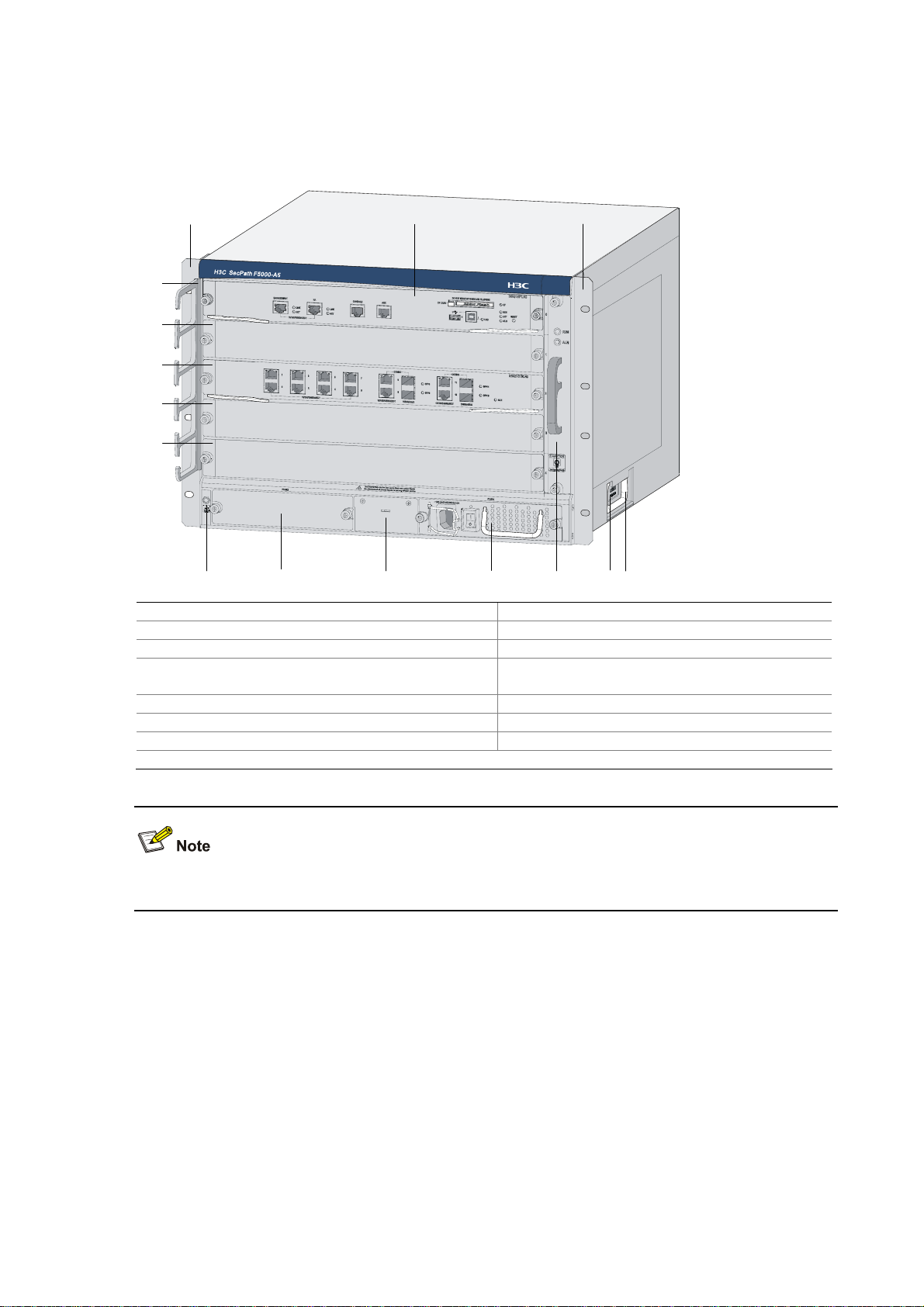
Figure 1-1 Front view of the F5000-A5
(1)
(15)
(14)
(13)
(12)
(11)
(2) (3)
(7) (5)(8)(9)(10)
(6)
(4)
(1) Left mounting bracket (2) Main processing unit (MPU)
(3) Right mounting bracket (4) Chassis handle
(5) Weight-bearing warning label (50 kg/110.2 lb.) (6) Fan tray
(7) AC power module (PWR1)
(8) Blank panel for PoE PSU (reserved PoE
slot)
(9) Blank panel for DC power module (PWR2) (10) ESD socket and silkscreen
(11) Blank panel for LPU (Slot 4) (12) Blank panel for LPU (Slot 3)
(13) Blank panel for LPU (Slot 2) (14) Blank panel for LPU (Slot 1)
(15) Cable management bracket
Currently, the device does not support power over Ethernet (PoE).
1-2
Page 9
Rear View
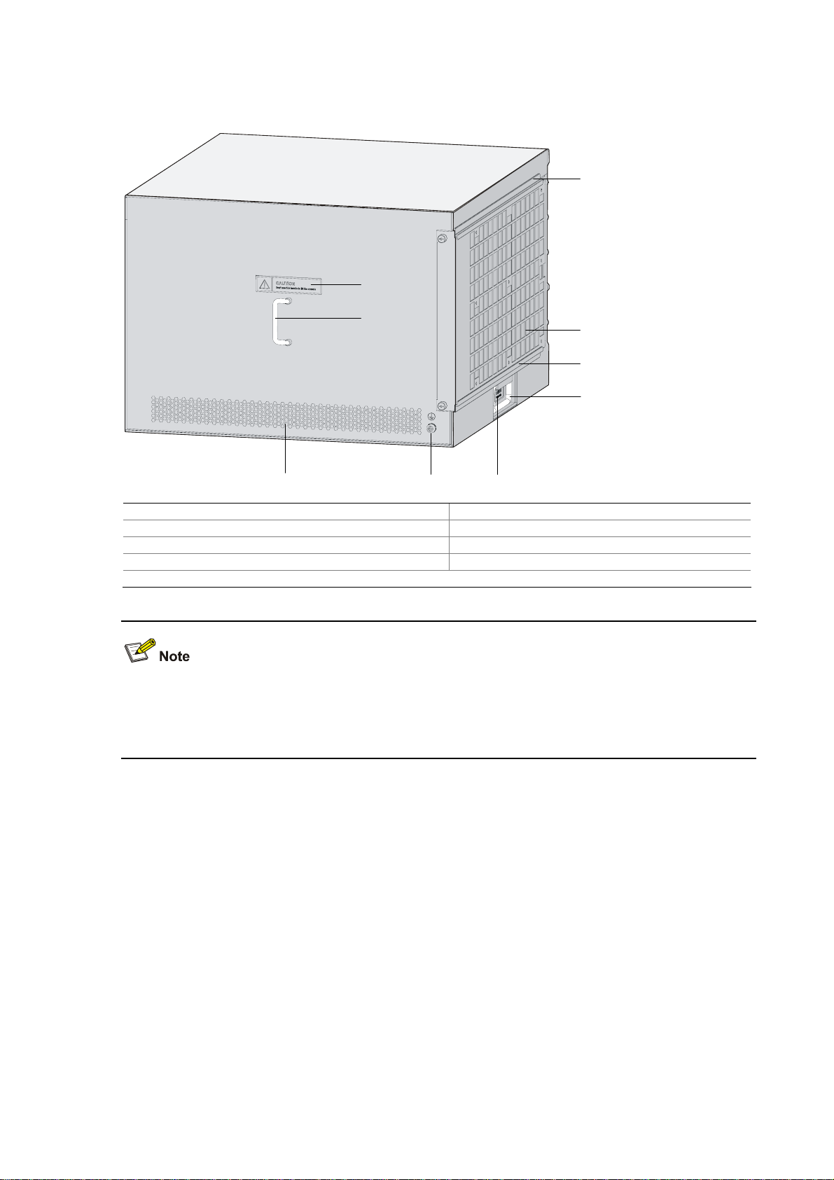
Figure 1-2 Rear view of the F5000-A5
(3)
(1)
(2)
(8)(9)
(7)
(4)
(5)
(6)
(1) Warning label (2) Handle on the rear chassis panel
(3) Upper slide rail for the air filter (optional) (4) Air filter (optional)
(5) Lower slide rail for the air filter (optional) (6) Chassis handle
(7) Weight-bearing warning label (50 kg/110.2 lb.) (8) Grounding screw and sign
(9) Vents
Do not hold the handle indicated by (2) in Figure 1-2 on the rear chassis panel to move the chassis
because it is designed for the convenience of the rear chassis panel removal, but not for bearing the
chassis weight.
1-3
Page 10
System Specifications
MPU–NSQ1MPUA0
Front view
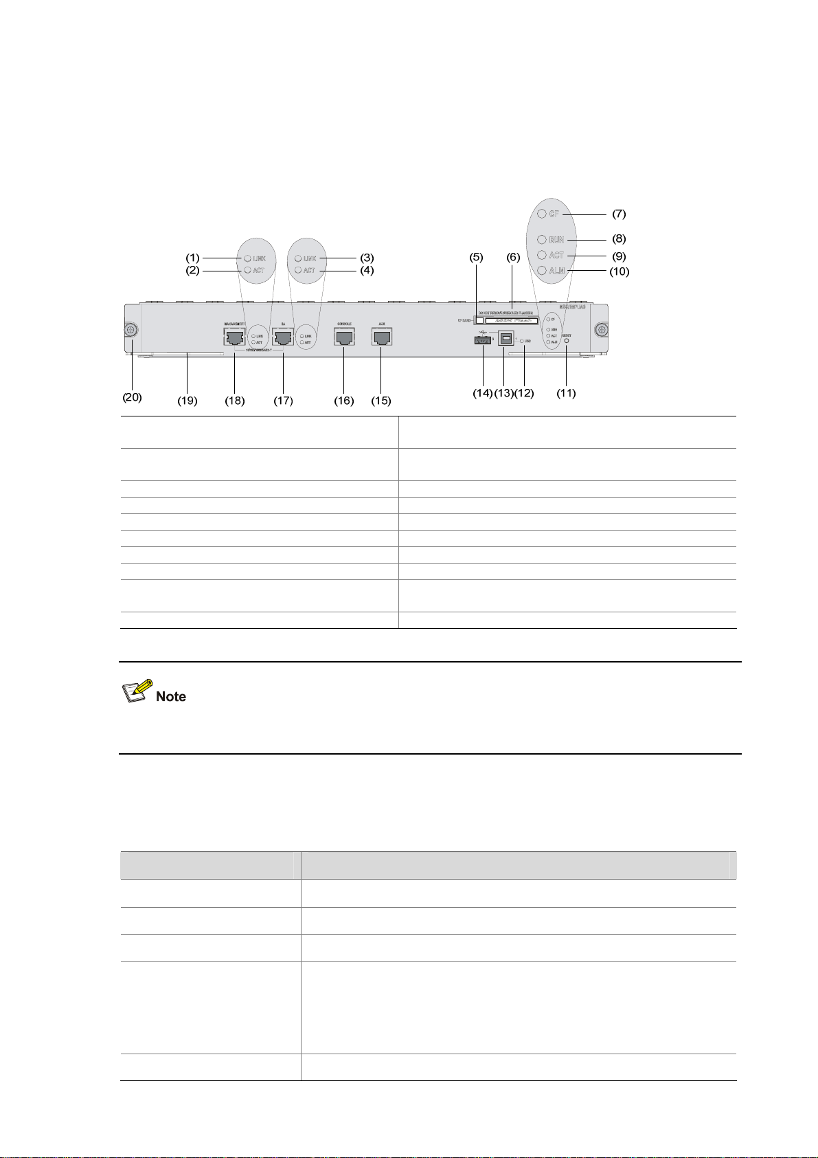
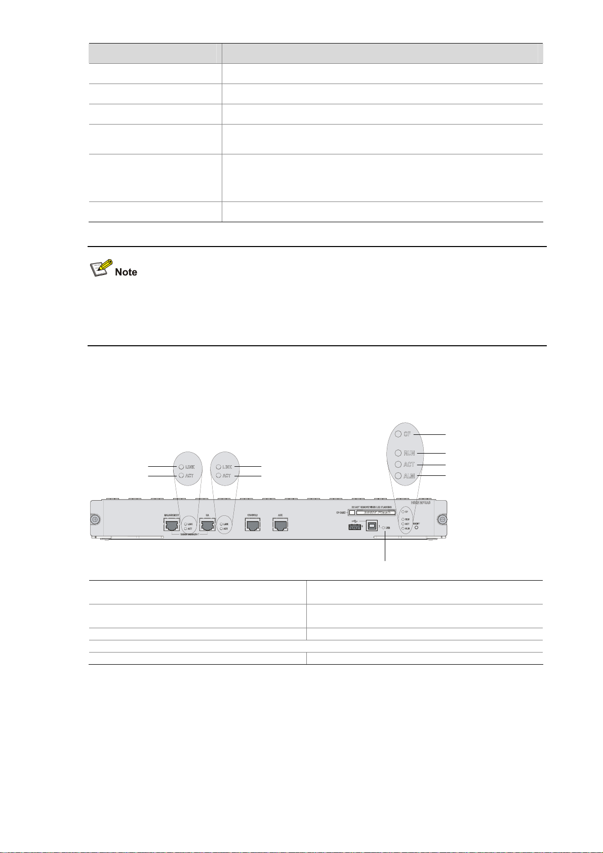
Figure 1-3 Front view of the MPU
(1) Link status LED of the management
Ethernet port (LINK)
(3) Link status LED of the HA port (LINK)
(5) CF card eject button (CF CARD) (6) CF card slot
(7) CF card LED (CF) (8) Run LED (RUN)
(9) Active LED of the MPU (ACT) (10) Alarm LED (ALM)
(11) Reset button (RESET) (12) USB interface 1 LED (USB1)
(13) USB interface 1 (1) (14) USB interface 0 (0)
(15) AUX port (AUX) (16) Console port (CONSOLE)
(17) HA port-10/100/1000BASE-T (HA)
(19) Ejector lever (20) Captive screw
(2) Data reception/transmission LED of the
management Ethernet port (ACT)
(4) Data reception/transmission LED of the HA port
(ACT)
(18) Management Ethernet port-10/100/1000BASE-T
(MANAGEMENT)
Currently, the device supports only one MPU and the MPU must be inserted in Slot 0.
Technical specifications
Table 1-1 Technical specifications of the MPU
Item Specification
Processor RMI XLR732 1 GHz
Processor cores 8
Flash 4 MB
DDR2 SDRAM
Memory type and size
2 memory slots
2 GB (default)
Memory modules must be used in pairs with the same size.
Console port 1 (9600 bps to 115200 bps, 9600 bps by default)
1-4
Page 11
Item Specification
AUX port 1 (9600 bps to 115200 bps, 9600 bps by default)
Management Ethernet port 1 (10Base-T/100Base-TX/1000Base-T)
HA port 1 (10Base-T/100Base-TX/1000Base-T)
CF card
z 256 MB by default for the built-in CF card
z 256 MB, 512 MB, or 1 GB for an optional external CF card
2 (USB 0: operating in the host mode; USB 1: operating in the device
USB interfaces
mode)
Reserved for future use
Reset button 1
z The flash is used for storing the boot file—the BootWare program.
z The memory is used for storing system data during operation and caching data in data forwarding.
z A CF card is used for storing the software system and configuration files of the device.
LEDs
Figure 1-4 LEDs on the MPU
(5)
(6)
(1)
(2)
(3)
(4)
(1) Link status LED of the management
Ethernet port (LINK)
(3) Link status LED of the HA port (LINK)
(9)
(2) Data reception/transmission LED of the
management Ethernet port (ACT)
(4) Data reception/transmission LED of the HA port
(ACT)
(7)
(8)
(5) CF card LED (CF) (6) Run LED (RUN)
(7) Data reception/transmission LED of the management Ethernet port/HA port (ACT)
(8) Alarm LED (ALM) (9) USB interface 1 LED
1) Device status LEDs
1-5
Page 12

Table 1-2 Description of the device status LEDs
LED Status Description
OFF No power input or the MPU is faulty.
Slow blinking (1 Hz) The MPU is operating normally.
RUN (green)
Fast blinking (8 Hz)
The application software is being loaded (in this state, never
power off the device or hot-swap the MPU; otherwise the
MPU may be damaged), or the MPU is not working.
Reset
The RUN LED goes off after the system is reset and flashes
fast on system startup.
OFF The MPU is in the standby state or there is no power input.
ACT (yellow)
ON The MPU is in the active state.
OFF The system is operating normally with no alarms.
A fault has occurred to the system. In this state, check the
system log immediately.
A critical fault has occurred to the system. In this state,
handle the fault immediately.
ALM (red)
ON
Fast blinking (8 Hz)
2) Management Ethernet port/HA port LEDs
Table 1-3 Description of the management Ethernet port/HA port LEDs
LED Status Description
OFF No link is present on the port.
LINK (green)
ON A link is present on the port.
ACT (yellow)
OFF No data is being transmitted or received on the port.
ON Data is being transmitted or received on the port.
3) USB interface LED
Table 1-4 Description of the USB interface LED
LED Status Description
OFF No host is connected to the device-mode USB interface.
A host is in connection with the device-mode USB interface. The
USB cable can be unplugged in this state.
Data is being transmitted or received through the device-mode
USB interface. Do not unplug the USB cable in this state.
USB (green)
ON
Blinking
USB interfaces are reserved for future use.
1-6
Page 13
4) CF card LED
Table 1-5 Description of the CF card LED
LED Status Description
OFF No CF card is present or the CF card is not recognizable.
CF (green)
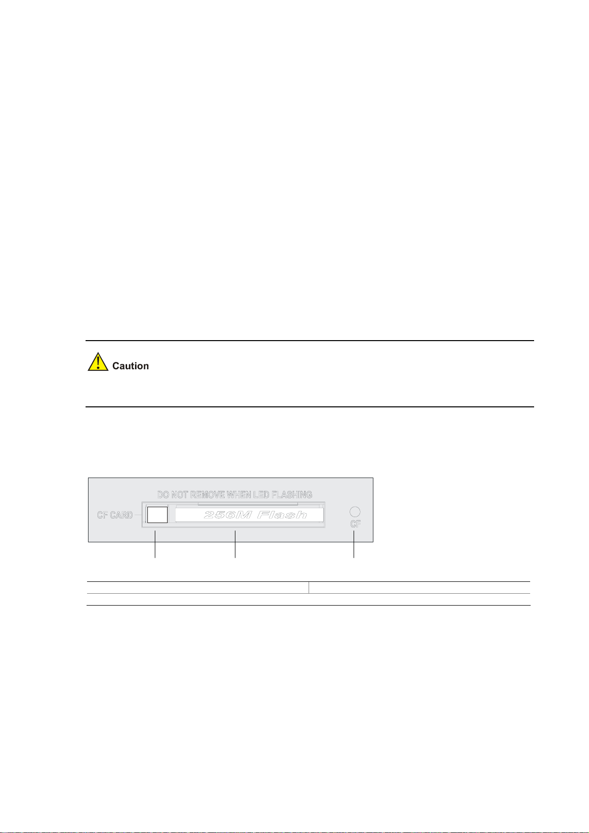
Do not remove the CF card when the CF LED is blinking. Otherwise, the files stored on the CF card will
be damaged.
LPU–NSQ1GT8C40
Introduction
An NSQ1GT8C40 line processing unit (LPU) provides eight electrical interfaces and four Combo
interfaces, delivering high-speed service process capabilities. Note that:
z An NSQ1GT8C40 LPU can be inserted in slot 1, 2, 3, or 4 of the F5000-A5.
z An F5000-A5 needs to be equipped with an MPU and at least one LPU to work normally.
ON A CF card is in position and has been detected.
Blinking
The system is accessing the CF card. Do not remove the CF
card in this state.
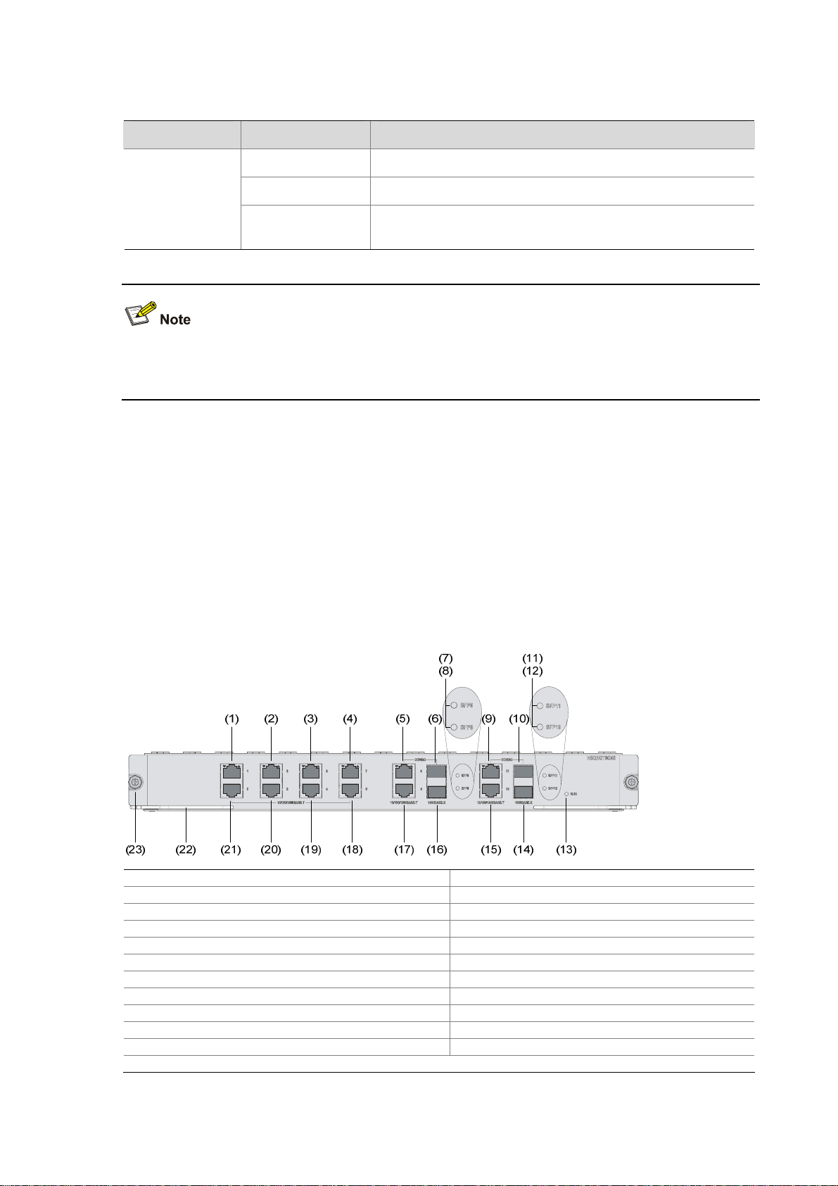
Figure 1-5 Front view of NSQ1GT8C40
(1) GE interface 1 (2) GE interface 3
(3) GE interface 5 (4) GE interface 7
(5) GE interface 9 (6) SFP interface 9
(7) SFP interface 9 LED (SFP9) (8) SFP interface 8 LED (SFP8)
(9) GE interface 11 (10) SFP interface 11
(11) SFP interface 11 LED (SFP11) (12) SFP interface 10 LED (SFP10)
(13) LPU LED (RUN) (14) SFP interface 10
(15) GE interface 10 (16) SFP interface 8
(17) GE interface 8 (18) GE interface 6
(19) GE interface 4 (20) GE interface 2
(21) GE interface 0 (22) Eject lever
(23) Captive screw
1-7
Page 14
Technical specifications
Table 1-6 Technical specifications of NSQ1GT8C40
Memory type and size
Item Description
DDR2 SDRAM
1 memory slot
512 MB (default), 1 GB (maximum)
8
Electrical interfaces
10 Mbps, half/full duplex
100 Mbps, half/full duplex
1000 Mbps, full duplex
4 (electrical/optical)
10 Mbps, half/full duplex
Combo interfaces
Electrical interfaces
100 Mbps, half/full duplex
1000 Mbps, full duplex
Optical interfaces 1000 Mbps, full duplex
Power consumption monitoring Supported
z A Combo interface is comprised of an electrical interface and a small form-factor pluggable (SFP)
interface.
z For an optical/electrical Combo interface, the default operating interface is the electrical interface.
z For a Combo interface, either the electrical interface or the optical interface can operate at one time.
You can use the combo enable { copper | fiber } command in interface view to switch between the
electrical and optical interfaces. For details about the combo enable { copper | fiber } command,
refer to H3C SecPath Series Security Products User Manual.
LEDs
Table 1-7 Description of the LEDs on NSQ1GT8C40
LED Status Description
OFF No power input or the LPU is faulty.
Slow blinking (1 Hz) The LPU is operating normally.
RUN
(green)
Fast blinking (8 Hz)
The application software is being loaded (in this state,
never power off the device or hot-swap the LPU; otherwise
the LPU may be damaged), or the LPU is not working.
Reset
The RUN LED goes off after the system is reset and
flashes fast on system startup.
1-8
Page 15
LED Status Description
OFF No link is present on the corresponding interface.
GE0 through
GE11
(yellow/green)
SFP8 through
SFP11
(yellow/green)
LPU–NSQ1XP20
Introduction
An NSQ1XP20 provides two Ten-gigabit small form-factor pluggable (XFP) interfaces, delivering
high-speed service process capabilities. The front panel of the LPU provides one LED for each interface.
Currently, this LPU supports only the LAN PHY mode, but not the WAN PHY mode. Note that:
Solid green A 1000 Mbps link is present on the interface.
Blinking green Data is being transmitted or received at 1000 Mbps.
Solid yellow A 10/100 Mbps link is present on the interface.
Blinking yellow Data is being transmitted or received at 10/100 Mbps.
OFF No fiber link is present on the interface.
Solid green A fiber link is present on the interface.
Blinking green Data is being transmitted or received at 1000 Mbps.
Solid yellow The optical module fails to be detected.
z NSQ1XP20 can be inserted in slot 1, 2, 3, or 4 of the F5000-A5.
z The F5000-A5 needs to be equipped with an MPU and at least one LPU to work normally.
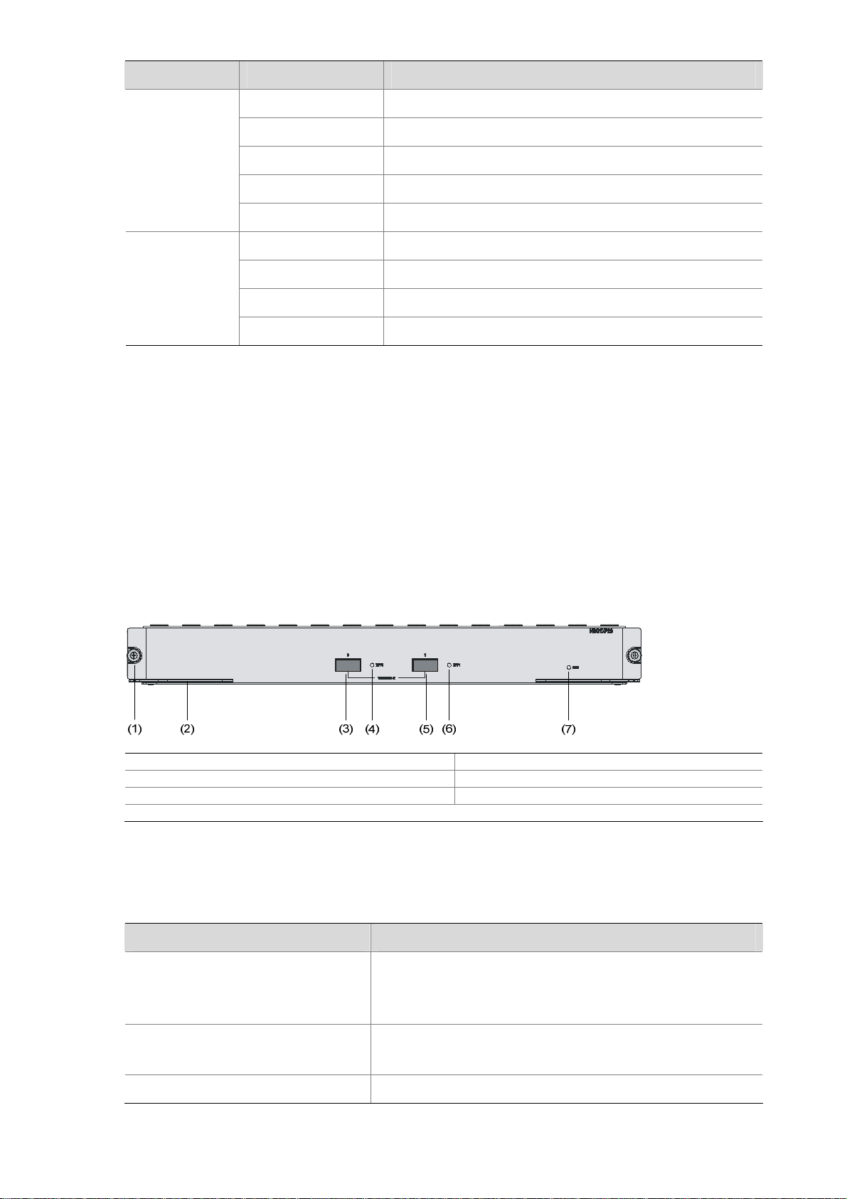
Figure 1-6 Front view of NSQ1XP20
(1) Captive screw (2) Eject lever
(3) XFP interface 0 (4) XFP interface 0 LED (XFP0)
(5) XFP interface 1 (6) XFP interface 1 LED (XFP1)
(7) LPU LED (RUN)
Technical specifications
Table 1-8 Technical specifications of NSQ1XP20
Item Description
DDR2 SDRAM
Memory type and size
1 memory slot
512 MB (default), 1 GB (maximum)
XFP interfaces
2
10GBASE-R
Power consumption monitoring Supported
1-9
Page 16

LPU LEDs
Table 1-9 Description of the LEDs on NSQ1XP20
LED Status Description
OFF No power input or the LPU is faulty.
Slow blinking (1 Hz) The LPU is operating normally.
RUN (green)
XFP0 (green)
XFP1 (green)
Fast blinking (8 Hz)
Reset
OFF No link is present on the interface.
ON A link is present on the interface.
Blinking Data is being transmitted or received on the interface.
OFF No link is present on the interface.
ON A link is present on the interface.
Blinking Data is being transmitted or received on the interface.
Dimensions and Weight
Table 1-10 Dimensions and weight of the F5000-A5
The application software is being loaded (in this state,
never power off the device or hot-swap the LPU; otherwise
the LPU may be damaged), or the LPU is not working.
The RUN LED goes off after the system is reset and
flashes fast on system startup.
Item Description
Dimensions without feet and mounting brackets
(H × W × D)
Weight (full configuration) 50 kg (110.23 lb.)
Voltage and Current
Table 1-11 Specifications of the voltage and current
Rated voltage range
Maximum input current
Maximum power consumption 650 W
308 × 436 × 476 mm (12.13 × 17.17 × 18.74 in.)
Item Description
AC powered: 100 VAC to 240 VAC; 50/60 Hz
DC powered: –48 VDC to –60 VDC
AC powered: 10 A
DC powered: 25 A
1-10
Page 17

Fan Tray
Table 1-12 Technical specifications of the fan tray
Rated voltage 12 VDC
Total fan power consumption 50 W
Dimensions (H × W × D) 227 × 31 × 413.3 mm (8.94 ×1.22 × 16.27 in.)
Table 1-13 Description of the fan tray LEDs
RUN (green) ON The fan tray is working normally.
ALM (red) ON The fan tray is faulty.
Item Specification
LED Status Description
The F5000-A5 supports automatic fan speed adjustment but not hot-swapping of the fan tray.
Operating Environment
Table 1-14 Operating environment specifications
Operating temperature 0°C to 45°C (32°F to 113°F)
Operating humidity 10% to 95%, noncondensing
Altitude –60 m to +4 km (–196.85 ft. to +2.49 miles)
Components
MPU–NSQ1MPUA0
Item Description
Processor
The NSQ1MPUA0 is an MPU that uses an RMI XLR732 1 GHz processor as the route processing
engine.
Flash
The flash size is 4 MB, of which 1 MB is used for storing the boot file—BootWare and the remaining
space for BootWare backup and storing important system parameters.
1-11
Page 18
Memory module
The memory module is used for storing data exchanged between the system and the CPU. The default
memory size of the MPU is 2 GB, which is the maximum memory size supported by the MPU. The MPU
provides two memory slots for memory modules of the same size.
You can use DDR2 SDRAM-1GB for the MPU of the device.
CF card
1) Introduction
A compact flash (CF) card is used for storing logs, host files, and configuration files.
The F5000-A5 is equipped with a 256 MB built-in CF card, which is identified with cfa0. In addition, the
device provides an external CF card slot to extend the local storage space. A CF card inserted into the
CF card slot is identified with cfb0.
The CF cards supported by the device are available in three sizes:
z 256 MB
z 512 MB
z 1 GB
Use CF cards provided by H3C only. The device may be incompatible with other CF cards.
2) CF card and slot
Figure 1-7 CF card and the LED
(1) (2) (3)
(1) Eject button (CF CARD) (2) CF card slot
(3) CF card LED (CF)
3) CF card LED
For the description of the CF card LED, see
Table 1-5.
1-12
Page 19
The CF card is hot-swappable. When the CF LED is blinking, do not unplug the CF card. Otherwise, the
file system on the CF card may be damaged.
Console port
1) Introduction
The F5000-A5 provides an RS232 asynchronous serial console port, which can be connected to a
computer for system debugging, configuration, maintenance, management, and host software loading.
2) Technical specifications
Table 1-15 Technical specifications of the console port
Connector type RJ-45
Item Description
Compliant standards RS232
Baud rate 9600 bps to 115200 bps, 9600 bps by default
Maximum transmission distance 15 m (49.21 ft.)
z Connection to an ASCII terminal
Services
z Connection to the serial interface of a local PC to run
the terminal emulation program
z Command line interface (CLI)
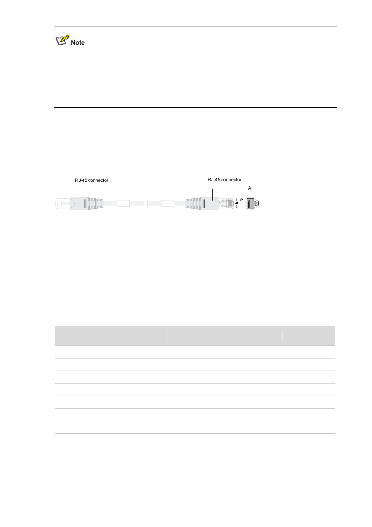
3) Console cable
The console cable is an 8-core shielded cable. The RJ-45 connector at one end of the cable is
connected to the console port on the device, and the DB-9 female connector at the other end is
connected to the serial port of a configuration terminal.
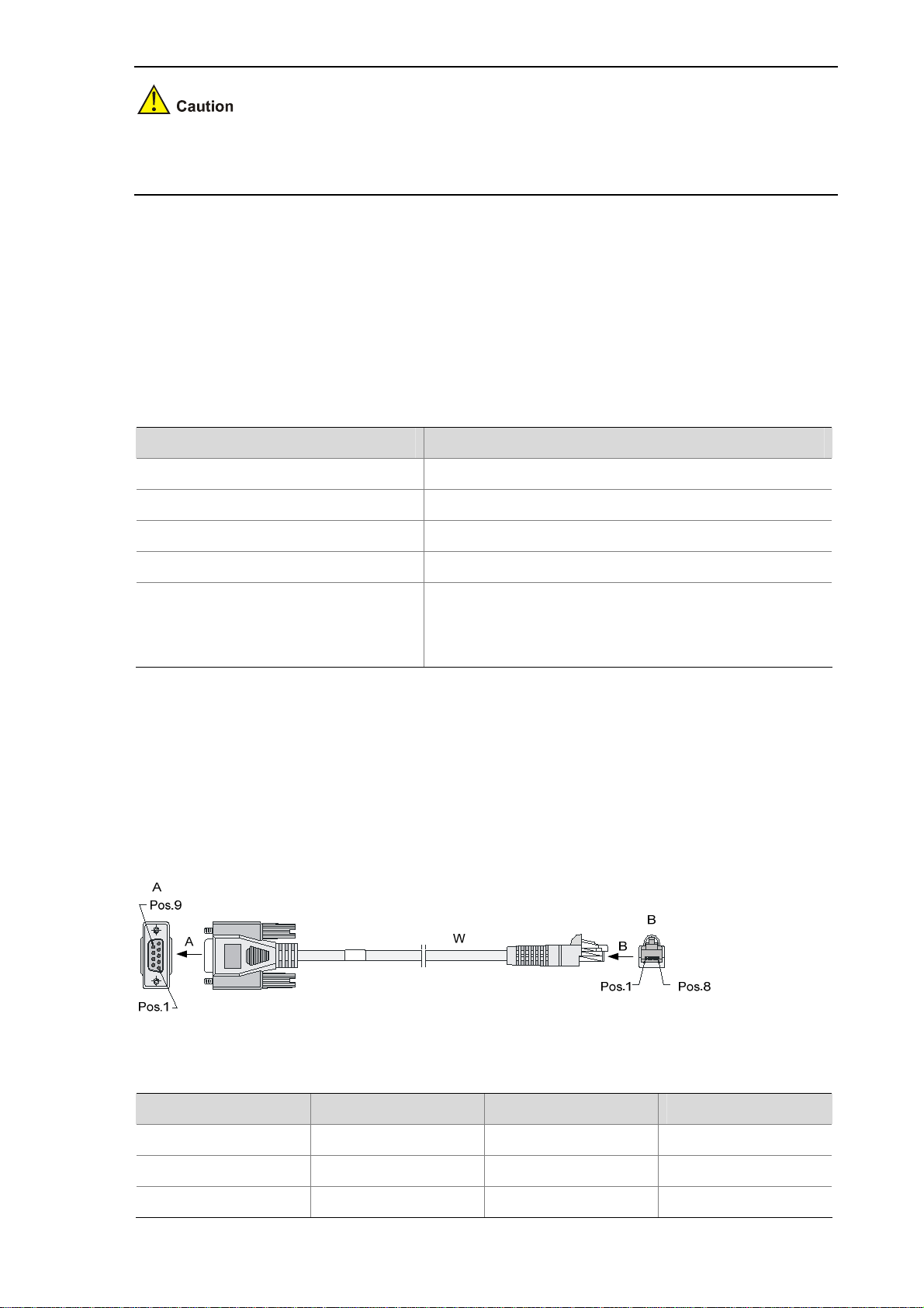
Figure 1-8 illustrates the console cable.
Figure 1-8 Console cable
Table 1-16 Console cable connector pinouts
RJ-45 pin Signal direction DB-9 Signal
1
2
3
Æ
Æ
Æ
8 CTS
6 DSR
2 RXD
1-13
Page 20

RJ-45 pin Signal direction DB-9 Signal
4
Å
1 DCD
5 — 5 GND
6
7
8
Å
Å
Å
3 TXD
4 DTR
7 RTS
For the connection of the console cable, refer to the section talking about connecting a console cable in
Chapter 4 “Installing the Firewall.”
AUX port
1) Introduction
The AUX port is an RS232 asynchronous serial port used for remote configuration or dialup backup.
You need to connect the local modem to the remote modem through the PSTN to reach the remote
device for remote system debugging, configuration, maintenance, and management. In case that the
console port is faulty, the AUX port can be connected to a terminal as a backup port of the console port.
For details, refer to Chapter 8 “Troubleshooting.”
2) Technical specifications
Table 1-17 Technical specifications of the AUX port
Item Description
Connector type RJ-45
Compliant standard RS232
Baud rate 9600 bps to 115200 bps, 9600 bps by default
Service
Connection to the serial interface of a remote PC through a pair of
modems to establish a dial-up connection with the remote PC
3) AUX cable
The AUX cable is an 8-core shielded cable. The RJ-45 connector at one end of the cable is connected
to the AUX port on the firewall, and the DB-25 male connector or DB-9 male connector at the other end
is connected to the serial port on a modem as needed.
1-14
Page 21
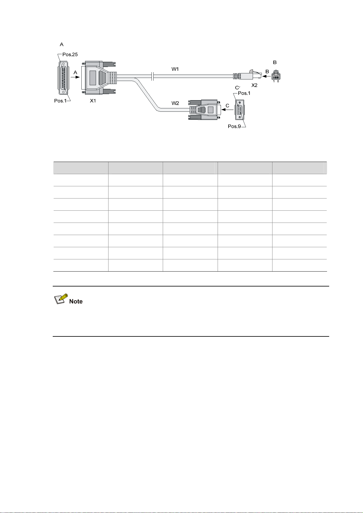
Figure 1-9 AUX cable
Table 1-18 AUX cable connector pinouts
RJ-45 Signal direction DB-25 DB-9 Signal
1
2
Æ
Æ
4 7 RTS
20 4 DTR
3
4
Æ
Å
2 3 TXD
8 1 DCD
5 — 7 5 GND
6
7
8
Å
Å
Å
3 2 RXD
6 6 DSR
5 8 CTS
For how to connect the AUX cable, refer to the section talking about connecting the AUX Cable to a
modem in Chapter 4 “Installing the Firewall.”
Management Ethernet port/HA port
The management Ethernet port is a 10Base-T/100Base-TX/1000Base-T RJ-45 auto-sensing interface.
It allows you to upgrade software and manage the device through a network management server,
without using any service interface of the device. The management Ethernet port is only for managing
the device and has no service processing capabilities such as data forwarding.
The high availability (HA) feature is mainly delivered through stateful failover and VRRP. The HA port is
a 10Base-T/100Base-TX/1000Base-T RJ-45 auto-sensing interface, which is used for synchronizing
link state packets in a dual-system network.
1-15
Page 22

Table 1-19 Technical specifications of the management Ethernet port/HA port
Item Description
Connector type RJ-45
Port quantity
1 management Ethernet port
1 HA port
Interface type Automatic MDI/MDIX
Frame formats
Ethernet_II
Ethernet_SNAP
10 Mbps, half/full duplex
Interface speed and duplex mode
100 Mbps, half/full duplex
1000 Mbps, full duplex
Maximum transmission distance 100 m (328.08 ft.)
Function Software upgrade and network management
The media dependent interface (MDI) standard is typically used on the Ethernet interface of network
adaptors. The media dependent interface crossover (MDI-X) standard is typically used on hubs or LAN
switches.
RESET button
The RESET button is used to reset the current MPU. The RUN LED goes off when the MPU is reset,
flashes fast (at 8 Hz) when BootWare is running, and flashes slowly (at 1 Hz) after the system is booted
and operates normally.
z If you perform no save operation before resetting the device, the current system configuration will
not be saved.
z Never press the RESET button when the device boots up with the RUN LED blinking fast or when
the device is accessing the CF card; otherwise, the file system of the device may be damaged.
Clock
The F5000-A5 is designed with an interface clock module, which provides the system time. You can set
the system time through the command line interface.
The clock module continues working even if a power failure occurs to the device, ensuring a correct
system time next time the device boots. With the device powered off, the clock module can work for at
least 10 years.
Note that:
1-16
Page 23

z Never replace the clock module battery when the device is powered on.
z The system time gets lost once the clock module battery is removed. You need to set the system
time again through the command line interface.
z Use the clock datetime time date command in user view to set the system date and time.
z For details about the clock datetime command, refer to H3C SecPath Series Security Products
User Manual.
LPU–NSQ1GT8C40
Ethernet interface introduction
NSQ1GT8C40 provides eight electrical interfaces (10Base-T/100Base-TX/1000Base-T) and four
Combo interfaces. A Combo interface consists of an electrical interface and an optical interface. The
default operating interface is the electrical interface.
z For the interface speed and duplex mode of electrical interfaces and the Combo interfaces
operating in electrical interface mode, see
Table 1-20.
Table 1-20 Interface speed and duplex mode of electrical interfaces
Interface speed Duplex mode
10 Mbps auto-sensing Half/full duplex
100 Mbps auto-sensing Half/full duplex
1000 Mbps auto-sensing Full duplex
The electrical interface LEDs are above the RJ-45 ports. The LEDs in triangle and inverted triangle
indicate the status of the lower and upper electrical Ethernet interfaces respectively. For the description
of the electrical interface LEDs, refer to
z The optical interface of a Combo interface supports 1000 Mbps in full duplex mode. It has an
Table 1-7.
interface LED on the right of the optical interface, indicating the status of the SFP optical interface.
For the description of the optical interface LEDs, refer to
Table 1-7.
For a Combo interface, either the electrical interface or the optical interface can operate at one time.
You can use the combo enable { copper | fiber } command in interface view to switch between the
electrical and optical interfaces. For details about the combo enable { copper | fiber } command, refer
to H3C SecPath Series Security Products User Manual.
1-17
Page 24

Technical specifications for Ethernet interfaces
z Technical specifications for electrical Ethernet interfaces
Table 1-21 Technical specifications for electrical Ethernet interfaces
Item Description
Connector type RJ-45
Interface type Automatic MDI/MDIX
Frame formats
Ethernet_II
Ethernet_SNAP
10 Mbps, half/full duplex
Interface speed and duplex mode
100 Mbps, half/full duplex
1000 Mbps, full duplex
z When 10/100 Mbps and half/full duplex mode are specified for an electrical Ethernet interface, the
electrical Ethernet interface operates in the forced mode. When 1000 Mbps or the speed and the
duplex mode are not simultaneously specified for an electrical Ethernet interface, the electrical
Ethernet interface operates in the auto-negotiation mode.
z No matter whether an electrical Ethernet interface operates in the forced or auto-negotiation mode,
it supports automatic MDI/MDIX.
z Technical specifications for optical Ethernet interfaces
Table 1-22 Technical specifications for GE optical interfaces
Item Description
Connector type SFP/LC
Compliant
standards
Type
Optical
transmit
power
802.3, 802.3u, and 802.3ab
Short-haul
multimode
optical
interface
module
(850 nm)
Medium-haul
single-mode
optical
interface
module (1310
nm)
Long-haul
optical
interface
module
(1310 nm)
Long-haul
optical
interface
module (1550
nm)
Ultra-long
haul optical
interface
module
(1550 nm)
Min –9.5 dBm –9 dBm –2 dBm –4 dBm –4 dBm
Max 0 dBm –3 dBm 5 dBm 1 dBm 2 dBm
Receiving
sensitivity
–17 dBm –20 dBm –23 dBm –21 dBm –22 dBm
Central wavelength 850 nm 1310 nm 1310 nm 1550 nm 1550 nm
1-18
Page 25
Item Description
Fiber type
Maximum
transmission
distance
62.5/125
μm
multimode
fiber
0.55 km
(0.34 miles)
9/125 μm
single-mode
fiber
10 km (6.21
miles)
9/125 μm
single-mode
fiber
40 km (24.86
miles)
9/125 μm
single-mode
fiber
40 km (24.86
miles)
9/125 μm
single-mode
fiber
70 km (43.50
miles)
Operating mode 1000 Mbps in full duplex mode
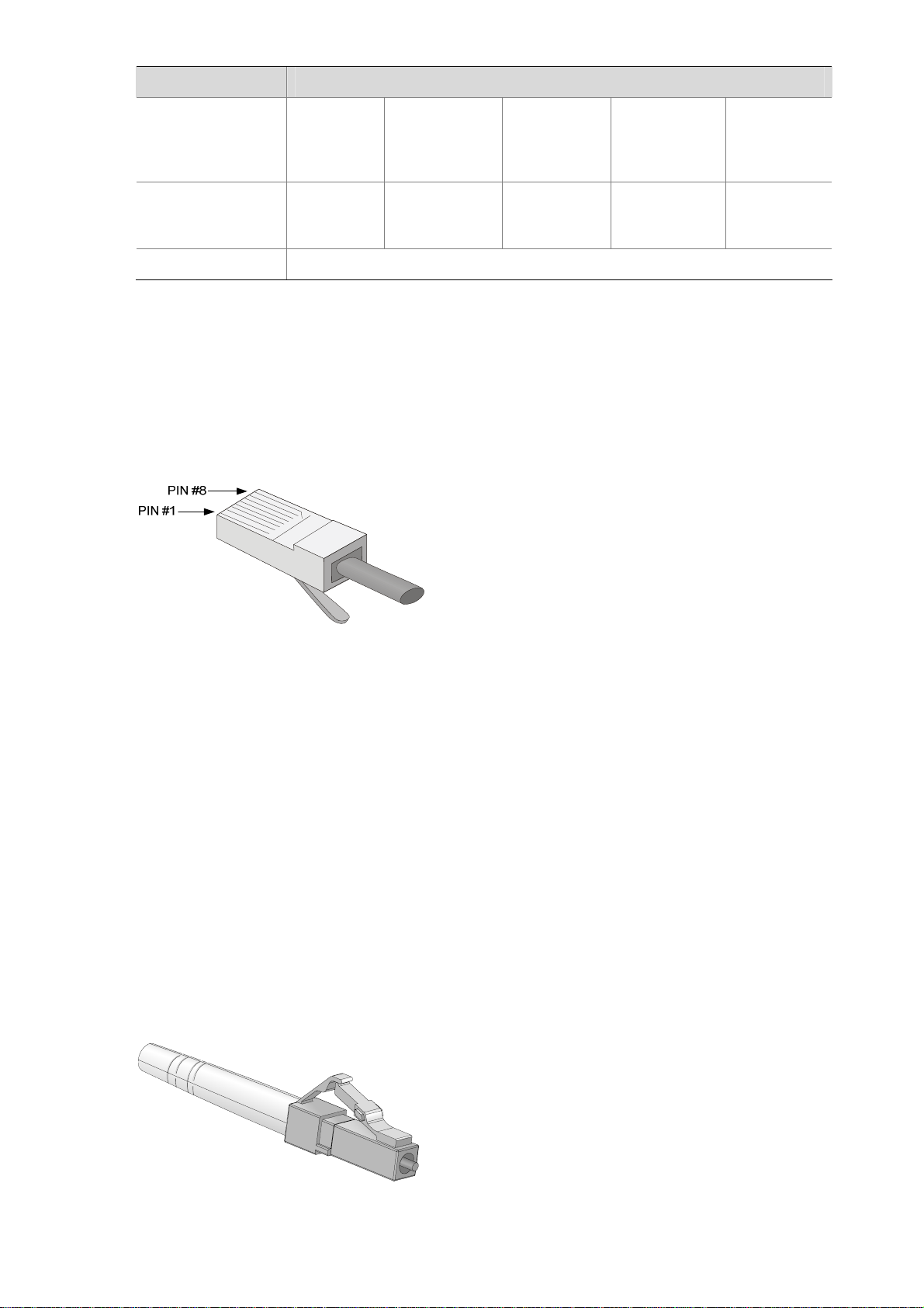
RJ-45 connector
The 10Base–T/100Base–TX/1000Base–T electrical Ethernet interfaces of the F5000-A5 use RJ-45
connectors and support automatic MDI/MDI-X. Category-5 twisted pair cables are used for RJ-45
connectors.
Figure 1-10 illustrates the RJ-45 connector.
Figure 1-10 RJ-45 connector
LC connector
Optical fiber connectors are indispensable passive components in optical fiber communication system.
Their application enables the removable connection between optical channels, which makes the optical
system debugging and maintenance more convenient and the transit dispatching of the system more
flexible.
Some optical fiber connecter types are as follows:
z LC: square optical fiber connector of the push-pull snap-in type
z SC: standard optical fiber connector
z FC: round optical fiber connector with screw thread
z ST: round plug-in optical fiber connector
z MT-RJ: square transceiver optical fiber connector
Currently, the optical Ethernet interfaces on NSQ1GT8C40 can only use LC connectors.
Figure 1-11 LC connector
1-19
Page 26
z Before using an optical fiber to connect a network device, verify that the optical fiber connector
matches the optical module.
z Before connecting an optical fiber, make sure the received optical power at the local end does not
exceed the upper threshold of the receiving optical power of the optical module. Otherwise, the
optical module may be damaged.
Cable connecting electrical Ethernet interfaces
Usually, you can use a Category-5 twisted pair cable to connect an electrical Ethernet interface. Figure
1-12 shows an Ethernet cable.
Figure 1-12 Ethernet cable
Ethernet cables fall into two categories:
z Standard cable: Also known as straight-through cable. At both ends of a standard cable, wires are
crimped in the RJ-45 connectors in the same sequence. A straight-through cable is used for
connecting a terminal (for example, a PC or router) to a hub or LAN switch. The cables delivered
with the firewall are straight-through cables.
z Crossover cable: At both ends of a crossover cable, wires are crimped in the RJ-45 connectors in
different sequences. A crossover cable is used for connecting two terminals (for example, PC or
router). You can make crossover cables by yourself as needed.
Table 1-23 Straight-through cable connector pinouts
RJ-45 Signal
1 TX+ White (Orange)
2 TX– Orange
3 RX+ White (Green)
Category-5
twisted pair
Signal direction RJ-45 pin
Æ
Æ
Å
1
2
3
4 — Blue — 4
5 — White (Blue) — 5
6 RX– Green
Å
6
7 — White (Brown) — 7
8 — Brown — 8
1-20
Page 27

Table 1-24 Crossover cable connector pinouts
RJ-45 Signal direction
1 TX+ White (Orange)
2 TX– Orange
3 RX+ White (Green)
Category-5
twisted pair
Signal direction RJ-45
Æ
Æ
Å
3
6
1
4 — Blue — 4
5 — White (Blue) — 5
6 RX– Green
Å
2
7 — White (Brown) — 7
8 — Brown — 8
z You can refer to the tables above when distinguishing between and preparing these two types of
Ethernet cables.
z When preparing Ethernet cables, follow the chromatogram given in the table to arrange the wires.
Otherwise, communication quality will be affected even if the two devices at both ends can
communicate.
z When preparing Ethernet cables, use shielded cables preferentially for electromagnetic
compatibility.
Fiber connecting optical Ethernet interfaces
You can use a single-mode or multimode fiber to connect a 1000 Mbps optical Ethernet interface and
select proper fibers for the installed 1000Base–X SFP optical modules (GE SFP transceivers for short).
Because the optical interfaces on these SFP transceivers use LC optical connectors, you must use
fibers with LC optical connectors. All SFP transceivers are hot-swappable.
z No SFP transceivers are shipped with the F5000-A5.
z Use only the SFP transceivers provided by H3C. The device cannot recognize other SFP
transceivers.
z For the connection of electrical Ethernet cables and optical fibers, refer to the section talking about
connecting Ethernet cables in Chapter 4 “Installing the Firewall.”
1-21
Page 28

LPU–NSQ1XP20
Introduction to 10 GE interfaces
NSQ1XP20 provides two XFP interfaces (10GBASE–R), which operate in the LAN PHY mode rather
than the WAN PHY mode. An XFP interface operating in the LAN PHY mode supports a maximum
data-rate of 10.3125 Gbps. The LED for an XFP interface is on the right of the interface, indicating the
status of the interface. For the description of the XFP interface LEDs, refer to
Technical specifications for 10 GE interfaces
Table 1-25 Technical specifications of the XFP interfaces
Item Description
Connector type XFP/LC
Physical layer 10GBASE–R
Interface speed LAN PHY mode: 10.3125 Gbps
Table 1-9.
Optical
transmit
power
Receiving sensitivity –7.5 dBm –10.3 dBm –11.3 dBm
Central wavelength 850 nm 850 nm 1310 nm
Maximum
transmission distance
Fiber type
Type Short-haul multimode
Min –7.3 dBm –8.2 dBm –1 dBm
Max –1.08 dBm 0.5 dBm 2 dBm
300 m (984.25 ft.) 300 m (984.25 ft.) 10 km (6.21 miles)
62.5/125 μm
multimode fiber
Medium-haul
single-mode
9/125 μm single-mode
fiber
Long-haul single-mode
9/125 μm single-mode
fiber
Cable connecting 10 GE interfaces
You can use a single-mode or multimode fiber to connect an XFP interface and select proper fibers for
the installed XFP optical modules (XFP transceivers for short). Since the optical interfaces on these
XFP transceivers use LC optical connectors, you must use fibers with LC optical connectors. All XFP
transceivers are hot-swappable.
Figure 1-11.
see
Figure 1-13 shows an XFP transceiver. For a fiber with LC connectors,
1-22
Page 29
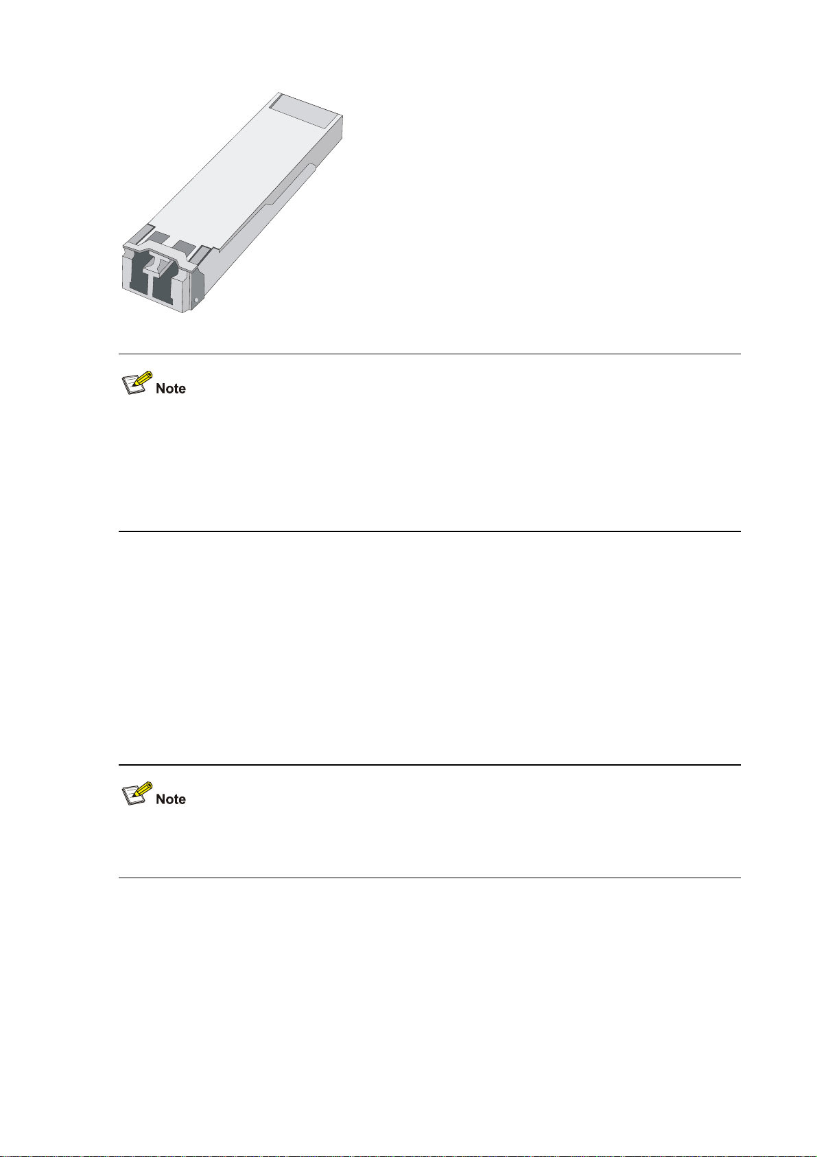
Figure 1-13 An XFP transceiver
z No XFP transceivers are shipped with the F5000-A5.
z Use only the XFP transceivers provided by H3C. The device cannot recognize other XFP
transceivers.
z For how to connect XFP transceivers, refer to the section talking about connecting Ethernet cables
in Chapter 4 “Installing the Firewall.”
Power Supply Module
The F5000-A5 supports both AC and DC power input. You can select an AC power module or a DC
power module. However, never install the two types of power PSUs in the same device.
The F5000-A5 needs only one PSU for normal operation of the system. But the device provides two
slots for 1+1 redundancy.
The PSUs are hot-swappable.
Online insertion and removal of a PSU refers to first switching off the power module and then removing
it from the device or inserting it into the device.
AC power module
Table 1-26 lists the specifications for the AC power module of the device.
1-23
Page 30
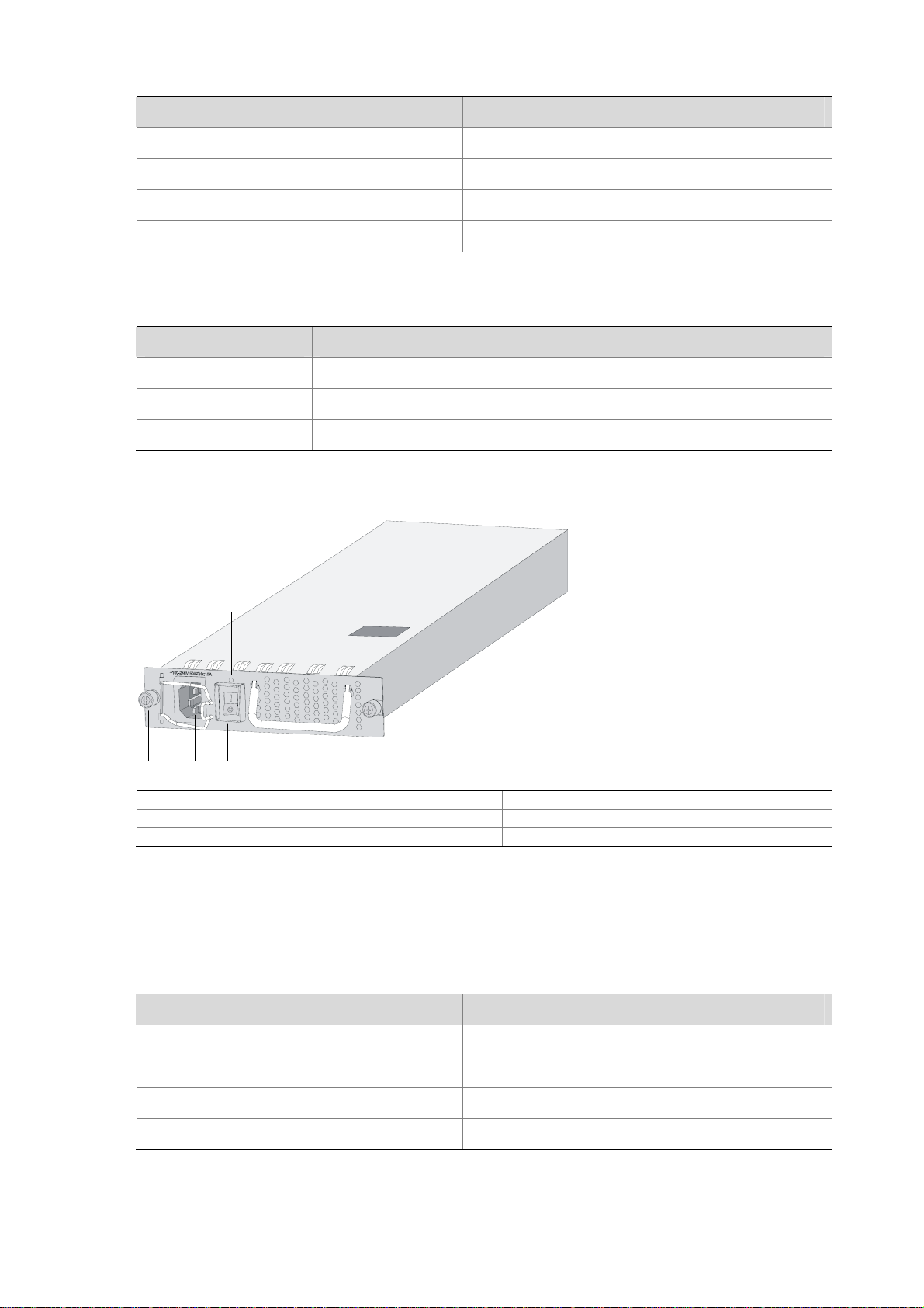
Table 1-26 AC power module specifications
Item Specification
Rated voltage range 100 VAC to 240 VAC; 50/60 Hz
Maximum input current 10 A
Maximum power consumption 650 W
Dimensions (H × W × D) 40.2 × 140 × 353.5 mm (1.58 × 5.51 ×13.92 in.)
Table 1-27 Description of the AC power LED
Status Description
OFF No power input is present.
Solid green The power module is working normally.
Solid red The power module is faulty.
Figure 1-14 AC power module
(5)
(1) (2) (3) (4)
(6)
(1) Captive screw (2) Bail latch
(3) Power socket (4) Power switch
(5) Power LED (6) PSU handle
DC power module
Table 1-28 lists the specifications for the DC power module of the device.
Table 1-28 DC power module specifications
Item Specification
Rated voltage range –48 VDC to –60 VDC
Maximum input current 25 A
Maximum power consumption 650 W
Dimensions (H × W × D) 40.2 × 140 × 353.5 mm (1.58 × 5.51 ×13.92 in.)
1-24
Page 31

Table 1-29 Description of the DC power LED
Status Description
OFF No power input is present.
Solid green The power module is working normally.
Solid red The power module is faulty.
Figure 1-15 DC power module
(1) Captive screw (2) Power input terminals
(3) Power switch (4) Power LED
(5) Power module handle
Port Lightning Arrester (Optional)
Before connecting an outdoor Ethernet cable to an Ethernet port, install a port lightning arrester to
protect the device against lightning strokes.
The following port lightning arrester can be installed on the F5000-A5. The specifications for the port
lightning arrester are as follows: Port protective unit–single port, maximum discharge current (8/20μs
waveform): 5 kA, output voltage (10/700μs waveform): core-core < 40 V, core-ground < 600 V.
For the installation of a port lightning arrester, refer to Chapter 4 “Installing the Firewall.”
Power Lightning Arrester (Optional)
Before connecting an outdoor AC power cable to the device, you can install a lightning protection
busbar at the AC power input end to protect the device against lightning strokes. In a heavy lightning
area, you are recommended to install a power lightning arrester.
1-25
Page 32

The following power lightning arrester can be installed on the F5000-A5. The specifications for the
power lightning arrester are as follows: Maximum discharge current: 6500 A, protection voltage: 220
VAC to 500 VAC.
For the installation of a power lightning arrester, refer to Chapter 4 “Installing the Firewall.”
Signal Lightning Arrester (Optional)
Generally, you need to install a signal lightning arrester between a signal cable and the connected
device. This can protect electronic devices against surge over-voltage resulting from lightning strokes
and other interferences, and minimize impact on the device.
The device supports three types of signal lightning arresters:
z Voltage-limiting protection parts–signal lightning arrester–maximum discharge current
2.5KA/protection voltage 25V—SMB-75J/SMB-75J-1W-10Mbps.
z Voltage-limiting protection parts–signal lightning arrester–maximum discharge current
2.5KA/protection voltage 25V-BNC-75K/BNC-75K-10Mbps.
z Voltage-limiting protection parts–single lightning arrester (U port)-maximum discharge current
3KA/comman mode 400 V/differential mode 170V-RJ11.
For the installation of a signal lightning arrester, refer to Chapter 4 “Installing the Firewall.”
System Software
The F5000-A5 uses the Comware V5 software platform, H3C’s core software platform.
Based on the IPv4/IPv6 dual stack, the Comware V5 software platform integrates link-layer protocols,
routing protocols, Multi-Protocol Label Switching (MPLS), virtual private network (VPN), security, and
other data communications features. It is scalable and portable because it adopts a componentized
architecture and effectively encapsulates and masks different operating systems and hardware.
1-26
Page 33

Table of Contents
2 Arranging Slots ands Numbering Interfaces··························································································2-1
Slot Arrangement····································································································································2-1
Numbering Interfaces······························································································································2-1
Examples ················································································································································2-2
Numbers of interfaces on NSQ1GT8C40························································································2-2
Numbers of interfaces on NSQ1XP20·····························································································2-2
i
Page 34

2 Arranging Slots ands Numbering Interfaces
Slot Arrangement
The F5000-A5 supports many types of interfaces, such as Console, AUX, GigabitEthernet, and
Ten-GigabitEthernet interfaces. This chapter describes how these interfaces are numbered.
Figure 2-1 Slot arrangement on the F5000-A5
The numbers 0 through 4 in Figure 2-1 represent Slot 0 through Slot 4 on the device respectively.
Actually, these numbers are not silk-screened on the device.
Numbering Interfaces
Except for user interfaces such as the Console port and AUX port, interfaces on the F5000-A5 are
numbered in the form of interface-type X/Y, where,
z interface-type: Type of the interface such as GigabitEthernet.
z X: Number of the slot where the LPU resides, in the range of 1 to 4.
z Y: Sequence number of the interface on the LPU, depending on the LPU model.
Note that:
z Interfaces on the same LPU have the same slot number X.
z For each type of interfaces, the sequence number Y starts from 0 and increases according to the
sequence on the LPU (from bottom to up or from left to right).
z The management Ethernet interface is permanently numbered as M-GigabitEthern et0/0.
2-1
Page 35

z The HA port is permanently Inner-Ethernet0/1.
Examples
Numbers of interfaces on NSQ1GT8C40
1) If the LPU is installed in Slot 1, GigabitEthernet interfaces on the LPU are numbered as follows:
z GigabitEthernet 1/0
z GigabitEthernet 1/1
z GigabitEthernet 1/2
z GigabitEthernet 1/3
z GigabitEthernet 1/4
z GigabitEthernet 1/5
z GigabitEthernet 1/6
z GigabitEthernet 1/7
z GigabitEthernet 1/8
z GigabitEthernet 1/9
z GigabitEthernet 1/10
z GigabitEthernet 1/11
2) If the LPU is installed in Slot 3, GigabitEthernet interfaces on the LPU are numbered as follows:
z GigabitEthernet 3/0
z GigabitEthernet 3/1
z GigabitEthernet 3/2
z GigabitEthernet 3/3
z GigabitEthernet 3/4
z GigabitEthernet 3/5
z GigabitEthernet 3/6
z GigabitEthernet 3/7
z GigabitEthernet 3/8
z GigabitEthernet 3/9
z GigabitEthernet 3/10
z GigabitEthernet 3/11
Numbers of interfaces on NSQ1XP20
1) If the LPU is installed in Slot 2, Ten-GigabitEthernet interfaces on the LPU are numbered as
follows:
z Ten-GigabitEthernet 2/0
z Ten-GigabitEthernet 2/1
2) If the LPU is installed in Slot 4, Ten-GigabitEthernet interfaces on the LPU are numbered as
follows:
z Ten-GigabitEthernet 4/0
z Ten-GigabitEthernet 4/1
2-2
Page 36

Table of Contents
3 Preparing for Installation ··························································································································3-1
Environment Requirements ····················································································································3-1
Temperature and Humidity Requirements ······················································································3-1
Cleanness Requirements ················································································································3-1
Ventilation Requirements ················································································································3-2
Electrostatic Discharge Prevention ·································································································3-2
Electromagnetic Interference Prevention ························································································3-4
Lightning Protection·························································································································3-4
Cabinet-Mounting Requirements·····································································································3-5
Safety Precautions··································································································································3-5
Safety Signs ····································································································································3-5
General Safety Recommendations ·································································································3-5
Electricity Safety ······························································································································3-5
Installation Tools, Meters and Devices ···································································································3-6
Checklist Before Installation····················································································································3-7
i
Page 37

3 Preparing for Installation
Environment Requirements
The device is designed for indoor application. To ensure the normal operation and prolong the service
life, the installation site must meet the requirements mentioned hereunder.
Temperature and Humidity Requirements
The temperature and humidity in the equipment room shall be maintained at an appropriate level.
A long-time high relative humidity will quite likely result in poor insulation performance, electric
leakage, mechanical property change, and corrosion.
A long-term low relative humidity will result in looseness of fastening screws owing to shrinkage of
insulation washers, or electrostatic discharge (ESD), which may damage the CMOS circuit on the
device.
A high temperature will speed up the aging of insulation materials, which greatly lower the device’s
reliability and shortens the service life.
Table 3-1 lists the requirements on temperature and humidity for the F5000-A5.
Table 3-1 Temperature and humidity requirements in the equipment room
Temperature Relative humidity
0°C to 45°C (32°F to 113°F) 10% to 95% (noncondensing)
Cleanness Requirements
Concentration limit of dust
Dust is harmful to the safe operation of the device. Dust on the chassis may result in static adsorption,
which causes poor contact between metal connectors or joints. The poor contact not only shortens the
service life of the device, but also brings about communication failures. Especially under the condition
of low indoor humidity, static adsorption is more likely to occur.
Table 3-2 lists the requirements on the dust concentration and diameters in the equipment room.
Table 3-2 Limitation on dust concentration and diameter in the equipment room
Diameter (μm) 0.5 1 3 5
Concentration limit (particles/m³) 1.4 x 10⁷ 7 x 10⁵ 2.4 x 10⁵ 1.3 x 10⁵
Concentration limit of harmful gases
Besides, the amounts of salt, acid, and sulfide in the equipment room should be strictly restricted.
Harmful gases could accelerate the corrosion of metal parts and the aging of some parts.
Table 3-3 lists the concentration limit of SO2, H2S, NH3, and CI2 in the equipment room.
3-1
Page 38

Table 3-3 Concentration limit of some harmful gases in the equipment room
Gas Max (mg/m3)
SO2 0.2
H2S 0.006
NH3 0.05
Cl2 0.01
Ventilation Requirements
The fans of the F5000-A5 draw air in through the inlet vents on the left and out through the exhaust
vents on the right.
Figure 3-1 Ventilation method for the F5000-A5
Make sure that:
There is a minimum clearance of 10 cm (3.9 in.) around the inlet vents and exhaust vents for heat
dissipation of the device chassis.
A ventilation system is available at the installation site.
Electrostatic Discharge Prevention
Generation and damage of static electricity
In the communication network to which the device is connected, static induction mainly results from:
External electrical fields such as outdoor high voltage power line or lightning
Indoor environment, flooring materials, and the device structure
Although the F5000-A5 adopts many antistatic measures, damage to board circuits or even the device
may still happen when the static electricity exceeds a certain limit.
Measures against ESD
To prevent electrostatic discharge (ESD),
3-2
Page 39

Make sure that the device and the floor are well grounded.
Take dust-proof measures for the equipment room.
Maintain the humidity and temperature at a proper level.
Always wear an ESD-preventive wrist strap or antistatic clothing when touching a circuit board or
optical module.
Place the removed MPU, LPU, memory module, or CF card on an antistatic workbench, with the
face upward, or put it into an antistatic bag.
Touch only the edges, instead of electronic components when observing or moving a removed
MPU, LPU, memory module or CF card.
Wearing an ESD-preventive wrist strap
Follow these steps to wear an ESD-preventive wrist strap:
Step1 Put on the ESD-preventive wrist strap, making sure that the strap makes good skin contact.
Step2 Plug the ESD-preventive wrist strap connector into the ESD socket on the chassis.
Step3 Make sure the chassis is well grounded.
For security, check the resistance of the ESD-preventive wrist strap. The resistance between human
body and ground should be in the range of 1 to 10 megohms.
3-3
Page 40

Figure 3-2 Wear an ESD-preventive wrist strap
(1) ESD-preventive wrist strap (2) Snap fastener
(3) ESD socket (4) Connector
Electromagnetic Interference Prevention
All possible interference sources, external or internal, affect the device in the way of capacitance
coupling, inductance coupling, electromagnetic radiation, and common impedance (including the
grounding system) coupling. To minimize the influence of interference sources on the device, take the
following into consideration:
Take effective measures to protect the power system from power grid interference.
Separate the protection ground of the device from the grounding device or lightning protection
grounding device of the common power supply equipments as far as possible.
Keep the device far from heavy-duty radio transmitters, radar transmitters, and high-frequency
devices.
Adopt electromagnetic shielding measures when necessary.
Lightning Protection
Although many measures have been taken to protect the device from lightning, damage to the device
may still happen if the lightning intensity exceeds a certain limit. To better protect the device from
lightning, do the following:
Ensure the PGND cable of the chassis is well grounded. Refer to “Connecting the PGND Cable” in
Chapter 4 “Installing the Firewall”.
Ensure the grounding terminal of the AC power socket is well grounded.
3-4
Page 41

Install a lightning arrester at the input end of the power supply to enhance the lightning protection
capability of the power supply.
Install a special lightning arrester at the input end of outdoor signal lines to which interface modules
of the device are connected to enhance the lightning protection capability.
For the installation of the power lightning arrester and signal lightning arrester, refer to “Installing a
Power Lightning Arrester (Lightning Protection Busbar) (Optional)” and “Selecting and Installing a
Signal Lightning Arrester (Optional)” in Chapter 4 “Installing the Firewall”
Cabinet-Mounting Requirements
When installing the firewall in a cabinet,
Install the firewall in an open cabinet if possible. If you install the firewall in a closed cabinet, make
sure that the cabinet is equipped with a good ventilation system.
Install the firewall on a shelf of the cabinet in view of the heavy weight of the firewall.
Make sure the cabinet is sturdy enough to support the weight of the firewall and installation
accessories.
Make sure that the size of the cabinet is appropriate for the firewall, and that there is enough
clearance around the left and right panels of the device for heat dissipation.
For heat dissipation and device maintenance, it is recommended that the front and rear of the
cabinet should be at least 0.8 m (31.5 in.) away from walls or other devices, and that the headroom
in the equipment room should be no less than 3 m (118.1 in.).
Safety Precautions
Safety Signs
When reading this manual, pay attention to the following:
: Means the reader be extremely careful. Improper operation may cause device damage
or bodily injury.
: Means the reader be careful. Improper operation may cause device malfunction.
General Safety Recommendations
Keep the firewall chassis and installation tools away from walk area.
Keep the firewall far away from a moist area and heat sources.
Unplug all external cables before moving the chassis.
Electricity Safety
Locate the emergency power switch in the equipment room before installation and maintenance so
that you can switch the power off in case of an accident.
3-5
Page 42

Make sure the device is correctly grounded.
Do not open or close the chassis cover when the device is powered on.
Connect the interface cables for the firewall correctly.
Use laser with caution. Do not directly stare into apertures or fiber connectors that emit laser
radiation.
Equip an uninterrupted power supply (UPS).
Disconnect the two power inputs to power off the firewall if there are two power inputs.
Avoid maintaining the firewall alone when it is powered on.
Installation Tools, Meters and Devices
Installation accessories supplied with the firewall
Power cable
Console cable
PGND cable
Mounting brackets
Cable management brackets
Blank panels
ESD-preventive wrist strap
User supplied tools
Philips screwdriver: P1-100 mm, P2-150 mm, and P3-250 mm
Flat-blade screwdriver: P4-75 mm
Screws with various specifications
Various meters and devices, such as configuration terminal and multimeter.
Optional cables
Reference
When installing and maintaining the device, you can refer to the following documents shipped with the
device:
H3C SecPath F5000-A5 Firewall Installation Manual
H3C SecPath F5000-A5 Firewall Electronic Documentation
You can obtain the latest documents from the documentation center on the website at
http://www.h3c.com.
3-6
Page 43

Checklist Before Installation
Table 3-4 Checklist before installation
Item Requirements
Ventilation
Temperature 0°C to 45°C (32°F to 113°F)
Relative humidity 10% to 95% (noncondensing)
Cleanness Dust concentration ≤ 3 × 10⁴ particles/m³
ESD prevention
Installation
site
Safety
precautions
EMI prevention
Lightning prevention
Electricity safety
Workbench
Cabinet-mounting
requirements
The firewall is far away from any moist area and heat source.
The emergency power switch in the equipment room is located.
There is a minimum clearance of 10 cm (3.9 in.) around
the inlet vents and exhaust vents for heat dissipation of
the router chassis.
A ventilation system is available at the installation site.
The equipment and the floor are well grounded.
The equipment room is dust-proof.
The humidity and temperature are at a proper level.
Always wear an ESD-preventive wrist strap and antistatic
clothing when touching a circuit board.
Place the removed MPU, LPU, memory module, or CF
card on an antistatic workbench, with the face upward, or
put it into an antistatic bag.
Touch only the edges, instead of electronic components,
when observing or moving a removed MPU, LPU,
memory module or CF card.
Take effective measures to protect the power system
from power grid interference.
Separate the protection ground of the router from the
grounding device or lightning protection grounding
device as far as possible.
Keep the router far away from heavy-duty radio
transmitters, radar transmitters, and high-frequency
devices.
Adopt electromagnetic shielding measures when
necessary.
The PGND cable of the chassis is well grounded.
The grounding terminal of the AC power socket is well
grounded.
A power lightning arrester is installed. (Optional)
A port lightning arrester is installed. (Optional)
Signal lightning arresters are installed. (Optional)
Equip an uninterrupted power supply (UPS).
In case of emergency during operation, switch off the
external power switch.
The workbench is stable enough.
The workbench is well grounded.
Install the firewall in an open cabinet if possible. If you
install the firewall in a closed cabinet, make sure that the
cabinet is equipped with a good ventilation system.
The rack is sturdy enough to support the weight of the
firewall and installation accessories.
The size of the cabinet is appropriate for the firewall.
The front and rear of the cabinet are at least 0.8 m (31.5
in.) away from walls or other devices.
3-7
Page 44

Item Requirements
Installation
tools
Reference
Installation accessories supplied with the firewall
User supplied tools
Documents shipped with the firewall
Electronic documents
3-8
Page 45

Table of Contents
4 Installing the Firewall································································································································4-1
Preparations············································································································································4-1
Installation Flowchart ······························································································································4-1
Installing the Firewall in a Rack ··············································································································4-1
Dimensions of the Firewall ··············································································································4-2
Installing an N68 Rack·····················································································································4-2
Installing Mounting Brackets onto the Firewall················································································4-2
Install the Firewall in a Rack············································································································4-3
Installing Generic Modules······················································································································4-4
PGND Cable Connection ························································································································4-5
Importance of the PGND Cable·······································································································4-5
Connecting the PGND Cable ··········································································································4-5
Installing a Port Lightning Arrester (Optional)·························································································4-6
Tools················································································································································4-7
Installation Procedures····················································································································4-7
Precautions······································································································································4-8
Installing an AC Power Lightning Arrester (Lightning Protection Busbar) (Optional) ·····························4-8
Selecting and Installing a Signal Lightning Arrester (Optional)·······························································4-9
Connecting the Power Cables ··············································································································4-10
Power Supply Interface and PGND Terminal················································································4-10
Connecting the AC Power Cord ····································································································4-10
Connecting the DC Power Cord ····································································································4-11
Connecting Interface Cables·················································································································4-13
Connecting Console Cable············································································································4-13
Connecting the AUX Port to a Modem ··························································································4-14
Connecting the Management Ethernet Port and HA Port Cables·················································4-15
Connecting Ethernet Cables ·········································································································4-16
Verifying Installation······························································································································4-18
i
Page 46

4 Installing the Firewall
Preparations
z Before installing the firewall, make sure that you have read through Chapter 3 “Preparing the
Installation.”
z Make sure all the requirements mentioned in Chapter 3 “Preparing the Installation” are satisfied.
Installation Flowchart
Figure 4-1 Installation flowchart for the F5000-A5
Start
Install the firewall to the
specified position
Connect the PGND cable
Connect the power cables
Connect the firewall to a
configuration terminal
Verify the installation
Turn on the power switch Troubleshoot
Is the power supply
normal?
Yes
Select and install LPUs
Connect the firewall to an
Ethernet network
Connect the firewall to a WAN
Verify the installation
No
Turn off the power switch
End
Installing the Firewall in a Rack
Install the firewall after you have completed the installation preparations.
4-1
Page 47

Dimensions of the Firewall
The F5000-A5 is designed to fit standard 19-inch racks. The following table describes the dimensions of
the firewall.
Table 4-1 Dimensions of the device
Item Description
Dimensions without foot pads and mounting
brackets (H × W × D)
308 × 436 × 476 mm (12.13 × 17.17 × 18.74 in.)
Installing an N68 Rack
The F5000-A5 firewall can be installed in an H3C N68 rack. For the installation of an N68 rack, refer to
N68 Cabinet Installation Guide.
Skip this procedure if the firewall is to be installed in a rack other than N68 rack.
Installing Mounting Brackets onto the Firewall
Before installing the firewall in a rack, you need to install the cable management bracket to the left
mounting bracket, and fix the left and right mounting brackets to the left and right sides of the firewall
respectively.
1) Install the cable management bracket
Before installing the mounting brackets to the chassis, screw the cable management bracket to the left
mounting bracket.
Figure 4-2 Install the cable management bracket
Figure 4-2 shows how to install the cable management bracket.
(1) (2)
(1) Left mounting bracket (2) Cable management bracket
2) Structure of mounting brackets
4-2
Page 48

Figure 4-3 Structure of mounting brackets
(1) (2)
(1) Left mounting bracket (2) Right mounting bracket
3) Install mounting brackets to the firewall
Before installing the firewall in the rack, fix the mounting brackets respectively to the left and right sides
of the front panel of the firewall.
Figure 4-4 shows how to install the mounting brackets.
Figure 4-4 Install mounting brackets to the firewall
Install the Firewall in a Rack
Follow these steps to install the firewall in a rack:
Step1 Check the grounding and stability of the rack.
Step2 Install a support tray on the rack for the firewall. Skip this step if a support tray is already installed.
Step3 Install the mounting brackets to the left and right sides of the front panel of the firewall. Refer to
“
Installing Mounting Brackets onto the Firewall” on page 4-2 for the installation.
4-3
Page 49

Step4 Put the firewall on the support tray and slide the firewall along the slide rails to an appropriate place.
Step5 Fix the firewall in the rack horizontally and firmly by fastening the mounting brackets onto the rack posts
with pan-head screws. The size of pan-head screws should satisfy the installation requirements
(maximally M6) and the surface of the screws should be anti-rust treated.
Figure 4-5 Install the firewall in a rack
Installing Generic Modules
Generic modules include RPU, LPU, AC/DC power module, fan, memory module, and CF card. For
their installation procedures, refer to Chapter 7 “Maintaining Hardware.”
4-4
Page 50

PGND Cable Connection
Importance of the PGND Cable
A correct connection of the protection ground (PGND) cable on the device chassis is an essential
safeguard against lightning strokes and electromagnetic interference (EMI). When installing or using
the firewall, make sure the PGND cable is correctly connected.
The power input end of the firewall is equipped with a noise filter. The neutral ground of the power input
end is directly connected to the chassis and is called PGND (also known as chassis ground). You need
to securely connect the PGND cable to the earth ground to safely lead induced current and leakage
current to the ground and reduce the electromagnetic susceptibility (EMS) of the firewall. The PGND
cable can also protect the firewall against high lightning voltage resulting from external network lines.
Connecting the PGND Cable
The grounding screw of the device is located on the lower right corner of the rear chassis panel and is
marked with a grounding sign, as shown in
Figure 4-6 Connect the grounding terminal of the PGND cable to the firewall
(3)
(2)(1)
(4)
(5)
(6)
Figure 4-6.
(1) Rear chassis panel (2) Grounding screw
(3) Grounding sign (4) Grounding screw hole
(5) OT terminal (6) PGND cable
Follow these steps to connect the PGND cable:
Step1 Remove the grounding screw from the firewall chassis.
Step2 Put the supplied OT terminal of the PGND cable on the grounding screw.
4-5
Page 51

Step3 Fasten the grounding screw, which is attached with the OT terminal, into the grounding screw hole with
a screwdriver.
Step4 Connect the other end of the PGND cable to the ground. Generally, the cabinets installed in equipment
rooms are equipped with a ground bar.
z If a grounding bar is available, you can connect the PGND cable of the firewall to the grounding bar
as follows: a) Use a cable stripper to strip off the insulation rubber about 15 mm (0.59 in.) from the
PGND cable. b) Wrap the naked part onto the grounding post of the grounding bar. c) Fix the
PGND cable onto the grounding post with a hex nut.
z If no grounding bar is available, connect the naked part of the PGND cable to the ground directly.
Figure 4-7 Connect the PGND cable to the grounding bar
(1) A hex nut (2) PGND cable
(3) Naked part of the PGND cable (4) Grounding post
(5) Grounding bar
z The resistance between the firewall chassis and the ground must be less than 5 ohms.
z Use the PGND cable provided with the firewall to connect the grounding bar in the equipment room.
Otherwise, the firewall may not be effectively grounded, which easily causes damage to the
firewall.
Installing a Port Lightning Arrester (Optional)
z Port lightning arresters are applicable to only 10/100 Mbps RJ-45 electrical Ethernet interfaces.
z No port lightning arresters are shipped with the firewall.
Before connecting an outdoor Ethernet cable to an Ethernet port, install a port lightning arrester in
between to protect the device against lightning strokes.
The following port lightning arrester can be installed on the F5000-A5. The specifications for the port
lightning arrester are as follows:
4-6
Page 52

Port protective unit–single port, maximum discharge current (8/20μs waveform): 5 kA, output voltage
(10/700μs waveform): core-core < 40 V, core-ground < 600 V.
Tools
z Philips or flat-blade screwdriver
z Multimeter
z Diagonal pliers
Installation Procedures
Follow these steps to install a port lightning arrester:
Step1 Use a double-faced adhesive tape to stick the port lightning arrester to the firewall. The port lightning
arrester should be as close to the grounding screw as possible.
Step2 Cut short the grounding cable of the port lightning arrester according to its distance to the grounding
screw. Fix the grounding cable to the grounding screw of the firewall.
Step3 Use a multimeter to check the connection between the grounding cable of the port lightning arrester and
the grounding screw of the chassis.
Step4 Follow the instructions to connect the port lightning arrester with a transit cable. Note that the external
cable should be connected to the IN end while the transit cable should be connected to the OUT end.
Verify that the ACU LED is normal.
Read the instructions of the port lightning arrester carefully before installation.
Step5 Bundle the cables with nylon wires neatly.
Figure 4-8 Install a port lightning arrester
4-7
Page 53

Precautions
Pay attention that the performance of the port lightning arrester may be affected in the following cases:
z The IN and OUT ends of the port lightning arrester are incorrectly connected. The IN end should be
connected to the external cable while the OUT end should be connected to the Ethernet interface
of the firewall.
z The port lightning arrester is not well grounded. Make sure that the grounding cable of the arrester
should be as short as possible and be well connected to the grounding screw of the firewall. Check
with a multimeter after connection.
z When more than one outdoor Ethernet cable are connected to the firewall, you need to install a port
lightning arrester for each outdoor Ethernet cable.
Installing an AC Power Lightning Arrester (Lightning Protection Busbar) (Optional)
No power lightning arresters are shipped with the firewall.
If an outdoor AC power cable is to be connected to the firewall, you should install a lightning protection
busbar at the AC power input end to protect the device against lightning strokes. You can use cable ties
and screws to fasten the lightning protection busbar on the cabinet, the workbench, or the wall in the
equipment room. With a lightning protection busbar, the AC current flows through the lightning
protection busbar before reaching the device.
Figure 4-9 Power lightning arrester
Grounding and polarity LED (red): When the LED is ON, a
cable connection error occurs (for example, no grounding cable
is connected or the live wire and zero wire are connected
incorrectly. In this case, check the power supply line.
Normal operation LED (green): When the
LED is ON, the protection circuit works
normally. Otherwise, the circuit is damaged.
Main electronic circuit board (built-in)
IEC-compliant socket,
connected to the power
supply in the equipment
room through a power
cable
Power switch
Automatic overload
protection device, which
can be manually reset
Multi-purpose socket, used
for connecting the power
supply of the router
Note that:
1) Make sure that the protection wire (PE) terminal of the power lightning arrester is well grounded
before using it.
4-8
Page 54

2) After the AC power cord connector of the device is plugged into a multi-purpose socket of the
power lightning arrester (lightning protection busbar), if the green LED is on while the red LED is off,
the lightning protection is functioning normally.
Pay attention when the red LED is on. You should correctly tell whether the grounding cable is not well
connected or the live and zero wires are reversely connected. You can use a multimeter to examine the
polarity of the multi-purpose socket of the power lightning arrester.
z If the live and zero wires are on the right and left respectively, supposing you are facing the socket,
the PE terminal of the power lightning arrester is not grounded.
z If not, the polarity of the power socket is reversed. In this case, open the power socket to correct the
polarity. After that, if the red LED is still on, the PE terminal is not grounded.
Selecting and Installing a Signal Lightning Arrester (Optional)
No signal lightning arresters are shipped with the firewall.
Generally, you need to install a signal lightning arrester between a signal cable and the connected
device, to protect the device against surge over-voltage resulting from lightning strokes and other
interferences.
Because the signal lightning arrester is serially connected to a signal cable, the signal lightning arrester
must satisfy the requirements of network performance indexes such as data transmission bandwidth, as
well as the lightning protection performance requirement. Therefore when selecting a signal lightning
arrester, you need to consider such performance indexes as lightning protection, bandwidth,
transmission loss, and interface type.
The device supports three types of signal lightning arresters:
z Voltage-limiting protection parts–signal lightning arrester–maximum discharge current
2.5KA/protection voltage 25V—SMB-75J/SMB-75J-1W-10Mbps
z Voltage-limiting protection parts–signal lightning arrester–maximum discharge current
2.5KA/protection voltage 25V-BNC-75K/BNC-75K-10Mbps
z Voltage-limiting protection parts–single lightning arrester (U port)-maximum discharge current
3KA/comman mode 400 V/differential mode 170V-RJ11
z The signal lightning arrester should be grounded to a place as near as possible. The grounding
resistance must be less than 4 ohms and must be less than 1 ohm in special cases.
z Connect the grounding cable to the special-purpose grounding cable of the signal lightning arrester
and connect it to the grounding grid, instead of connecting it to the lightning rod or lightning belt.
4-9
Page 55

Connecting the Power Cables
Power Supply Interface and PGND Terminal
You can use AC power modules for AC power input or DC power modules for DC power input for the
F5000-A5.
Table 4-2 Power supply interface and PGND terminal of the device
AC power socket (for the AC-powered firewall) 100 VAC to 240 VAC
DC power socket (for the DC-powered firewall) –60 VDC to –48 VDC
PGND terminal
Connecting the AC Power Cord
Table 4-2 shows the specifications for the power supply interface and PGND terminal.
Item Description
Connected to the ground through a PGND cable.
For the connection of the grounding terminal,
refer to “
PGND Cable Connection” on page 4-5.
AC power supply
Rated voltage range: 100 VAC to 240 VAC, 50 Hz/60 Hz
AC power socket
Figure 4-10 illustrates an AC power module.
Figure 4-10 AC power module
(5)
(1) (2) (3) (4)
(6)
(1) Captive screw (2) Bail latch holder
(3) AC power socket (4) Power switch
(5) Power LED (6) Power module handle
Before connecting the power supply, check the following:
z Use a three-terminal, single-phase power connector with a grounding contact.
z Ground the power supply reliably. Normally, the grounding contact of the power supply system in a
building was buried during construction and cabling.
z Make sure that the power supply of the building is well grounded before connecting the AC power
cord.
4-10
Page 56

Connection procedure
Follow these steps to connect the AC power cord:
Step1 Make sure that the PGND terminal is securely connected to the ground.
Step2 Move the power switch of the power module to the OFF position.
Step3 Move the bail latch holder to the left.
Step4 Connect one end of the supplied AC power cord to the AC power socket of the firewall, and the other
end to an AC power outlet.
Step5 Move the bail latch holder to the right to hold the power lord in position.
Step6 Move the power switch to the ON position.
Step7 Check the status of the power LED, PWR, on the front panel of the firewall. For the status of the power
LED, see
Table 4-3.
Table 4-3 Description of power LED status
Status Description
OFF No power is input.
Solid green The power module works normally.
Solid red The power module is faulty.
Figure 4-11 Connect the AC power cord
(1) (2) (3) (4)
(5)
(6) (7)
(1) Bail latch holder (2) AC power cord
(3) Power socket (4) Power LED
(5) Power switch (6) Power module holder
(7) Captive screw
Connecting the DC Power Cord
DC power supply
Rated voltage range: –48 VDC to –60 VDC.
DC power module
Figure 4-12 illustrates a DC power module.
4-11
Page 57

Figure 4-12 DC power module
(1) Captive screw (2) DC input terminals
(3) Power switch (4) Power LED
(5) Power module handle
DC power cables
Figure 4-13 DC power cables
(1) (2) (3) (4) (5) (6)
(9) (8) (7)
(1) Naked crimping terminal, OT, 6mm^2, M4, tin plating, naked ring terminal, 12 to 10 AWG
(2) Heat shrink tube
(3) Label 1 (+)
(4) Power cable, 600V, UL10455, 5.3 mm^2, 10AWG, black, 45 A
(5) Main label
(6) Heat shrink tube
(7) Power cable, 600 V, UL10455, 5.3 mm^2, 10AWG, blue, 45 A
(8) Label 2 (–)
(9) Common terminal, conductor cross section, 6mm^2, 20mm, 30 A, insertion depth 12 mm, black
Formula for calculating the cross section area of a DC power cable: S=2*I*L/(57*∆U)
Where,
I: Current in amperes.
L: Length of the power cable in meters.
∆V: Voltage drop on the power cable from the power distribution frame (PDF) to the firewall, usually, 3.2
V.
S: Cross section area of the power cable in square millimeters.
Connection procedure
Follow these steps to connect the DC power cables:
4-12
Page 58

Step1 Move the power switch to the OFF position.
Step2 Remove the DC input terminals with a Philips screwdriver.
Step3 Attach the end marked with “–“ of the supplied blue DC power cable to the negative terminal (–) on the
power module and fasten the screw.
Step4 Attach the end marked with “+“ of the supplied blue DC power cable to the passive terminal (+) on the
power module and fasten the screw.
Step5 Connect the other end of the DC power cables to the wiring terminals of the DC power supply.
Step6 Move the power switch to the ON position.
Step7 Check the status of the power LED, PWR, on the front panel of the firewall. For the status of the power
LED, see
When connecting DC power cables, pay attention to the labels on the power cable to avoid incorrect
connection.
Table 4-3.
Connecting Interface Cables
Connecting Console Cable
Follow these steps to connect the Console cable:
Step1 Select a configuration terminal.
A configuration terminal can be a standard ASCII terminal with an RS232 serial interface, or a common
PC.
Step2 Connect the Console cable.
Disconnect the power supply to the firewall. Connect the RJ-45 connector of the console cable to the
Console port on the firewall, and the DB-9 female connector to the serial interface on the configuration
terminal.
Step3 Power on the firewall after verifying the connection.
After performing verification, power on the devices. The configuration terminal displays the startup
banner of the firewall. For details, refer to “Firewall Power-on” in Chapter 5 “Starting and Configuring the
Firewall.”
4-13
Page 59

Figure 4-14 Connect the Console cable
(1) Console port (2) RJ-45 connector
(3) Serial interface on the configuration terminal (4) DB-9 (female) connector
(5) Console cable
Connecting the AUX Port to a Modem
The AUX port is usually used for remote configuration or dial backup. You need to connect the local
modem to the remote modem through PSTN and then to the remote device.
Follow these steps to connect the AUX cable:
Step1 Connect the RJ-45 connecter of the AUX cable to the AUX port on the firewall.
Step2 Plug the DB-25 (male) or DB-9 (female) connector of the AUX cable into the serial interface on the
analog modem.
4-14
Page 60

Figure 4-15 Connect the AUX cable
(1)
(2)
(3)
(4)
(5)
(1) AUX port (AUX) (2) RJ-45 connector
(3) AUX cable (4) Modem
(5) DB-25 (male) or DB-9 (female) connector
Connecting the Management Ethernet Port and HA Port Cables
The management Ethernet port and HA port are 10Base-T/100Base-TX/1000Base-T RJ-45
auto-sensing interfaces. They are used to upgrade software and manage the device through a network
management server, without using any service interface of the device. The management Ethernet port
and HA port are only for managing the device and have no service processing capabilities such as data
forwarding.
With support for automatic MDI/MDIX, the management Ethernet port and HA port use either a
straight-through cable or a crossover cable for connection to a configuration terminal.
Follow these steps to connect the management Ethernet port or the HA port to the configuration
terminal (take the management Ethernet port for example):
Step1 Turn off the power switches on all power modules of the firewall. Connect the RJ-45 connector of the
console cable to the Console port on the firewall, and the DB-9 female connector to the serial interface
on the configuration terminal.
Step2 Connect one end of the Ethernet cable to the management Ethernet port on the firewall and the other
end to the Ethernet interface on the configuration terminal.
4-15
Page 61

Figure 4-16 Connect the management Ethernet port
(1) Management Ethernet port (MANAGEMENT) (2) RJ-45 connector of the Ethernet cable
(3) Console port (CONSOLE) (4) RJ-45 connector of the Console cable
(5) Ethernet interface on the terminal (6) RJ-45 connector of the Ethernet cable
(7) Serial interface on the terminal (8) DB-9 (female) connector
(9) Ethernet cable (10) Console cable
Connecting Ethernet Cables
Connecting an electrical Ethernet interface
Follow these steps to connect an electrical Ethernet interface:
Step1 Connect one end of the Ethernet cable to the electrical Ethernet interface on NSQ1GT8C40 and the
other end to the Ethernet interface on the peer device. Because a 10Base-T/100Base-TX/1000Base-T
electrical Ethernet interface supports automatic MDI/MDIX, it can use either a straight-through cable or
crossover cable for connection.
Step2 Check the LED of the electrical Ethernet interface after power-on. For the status of the LED, refer to the
table describing the behaviors of LPU LEDs in Chapter 1 “Firewall Overview.”
Connecting an optical Ethernet interface
SFP optical interfaces and XFP optical interfaces are connected in the same way. In the following
description, an SFP optical interface is used as an example.
Follow these steps to connect an SFP optical Ethernet interface:
Step1 Remove the dust cover from the optical Ethernet transceiver receptacle.
4-16
Page 62

Figure 4-17 Remove the dust cover
Step2 Align an SFP transceiver with the optical SFP transceiver receptacle, with the side having a release
lever facing outward. Then insert it into the receptacle.
Figure 4-18 Insert an optical transceiver
Step3 Identify the Rx and Tx ports on the SFP transceiver module. Plug the two LC connectors at one end of
the fiber cable into the Rx and Tx ports of the local SFP transceiver and the two LC connectors at the
other end to the Rx and Tx ports of the peer SFP transceiver. Note that the two LC connectors at each
end of the fiber cable should be inserted into a Tx port and Rx port respectively.
4-17
Page 63
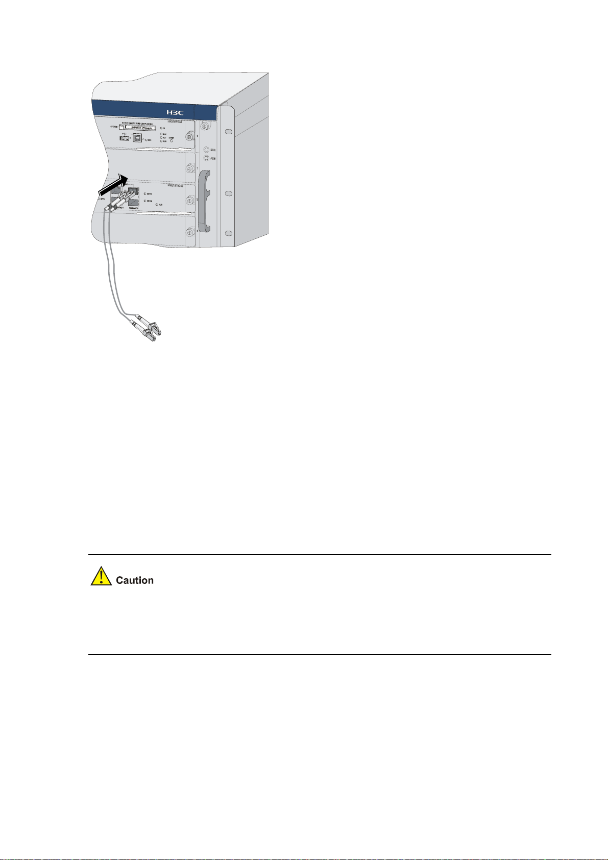
Figure 4-19 Connect fiber cables
Step4 After power-on, check the SFP LED. For the status of the SFP LED, refer to the table describing the
behaviors of the LEDs on NSQ1GT8C40 in Chapter 1 “Firewall Overview.”
Upon the connection of an XFP transceiver, you need to check the XFP LED. For details, refer to the
table describing the behaviors of the LEDs on NSQ1XP20 in Chapter 1 “Firewall Overview.”
Note that:
z Avoid excessively bending the optical fiber cables, with the curvature radium less than 10 cm (3.9
in.).
z Ensure that the Tx and Rx of the SFP/XFP transceiver module are connected correctly.
z Keep the end-faces of optical fiber cables clean.
z Do not look directly into an open optical Ethernet interface, because invisible rays emitted from the
optical Ethernet interface may hurt your eyes.
z Cover the dust cover if no optical transceiver is connected to the optical Ethernet interface.
Verifying Installation
Each time you power on the firewall during installation, you verify that:
z There is enough space around the firewall for heat-dissipation and the workbench is stable
enough.
z The power supply matches the requirements of the firewall.
z The PGND cable of the firewall is correctly connected.
4-18
Page 64

z The firewall is correctly connected to other devices, such as the configuration terminal.
It is very important to verify the installation because instability and poor grounding of the firewall and an
unmatched power supply will affect the operation of the firewall.
4-19
Page 65

Table of Contents
5 Starting and Configuring the Firewall ·····································································································5-1
Setting up a Configuration Environment·································································································5-1
Connecting the Firewall to a Configuration Terminal······································································5-1
Setting the Parameters for the Configuration Terminal···································································5-1
Firewall Power-on ···································································································································5-4
Checklist for Firewall Power-on·······································································································5-4
Powering on the Firewall·················································································································5-5
Checklist/Operations after Power-on·······························································································5-5
Startup Process·······································································································································5-5
Configuration Fundamentals···················································································································5-6
Command Line Interface·························································································································5-7
Features of the Command Line Interface························································································5-7
Command Line Interface·················································································································5-7
i
Page 66
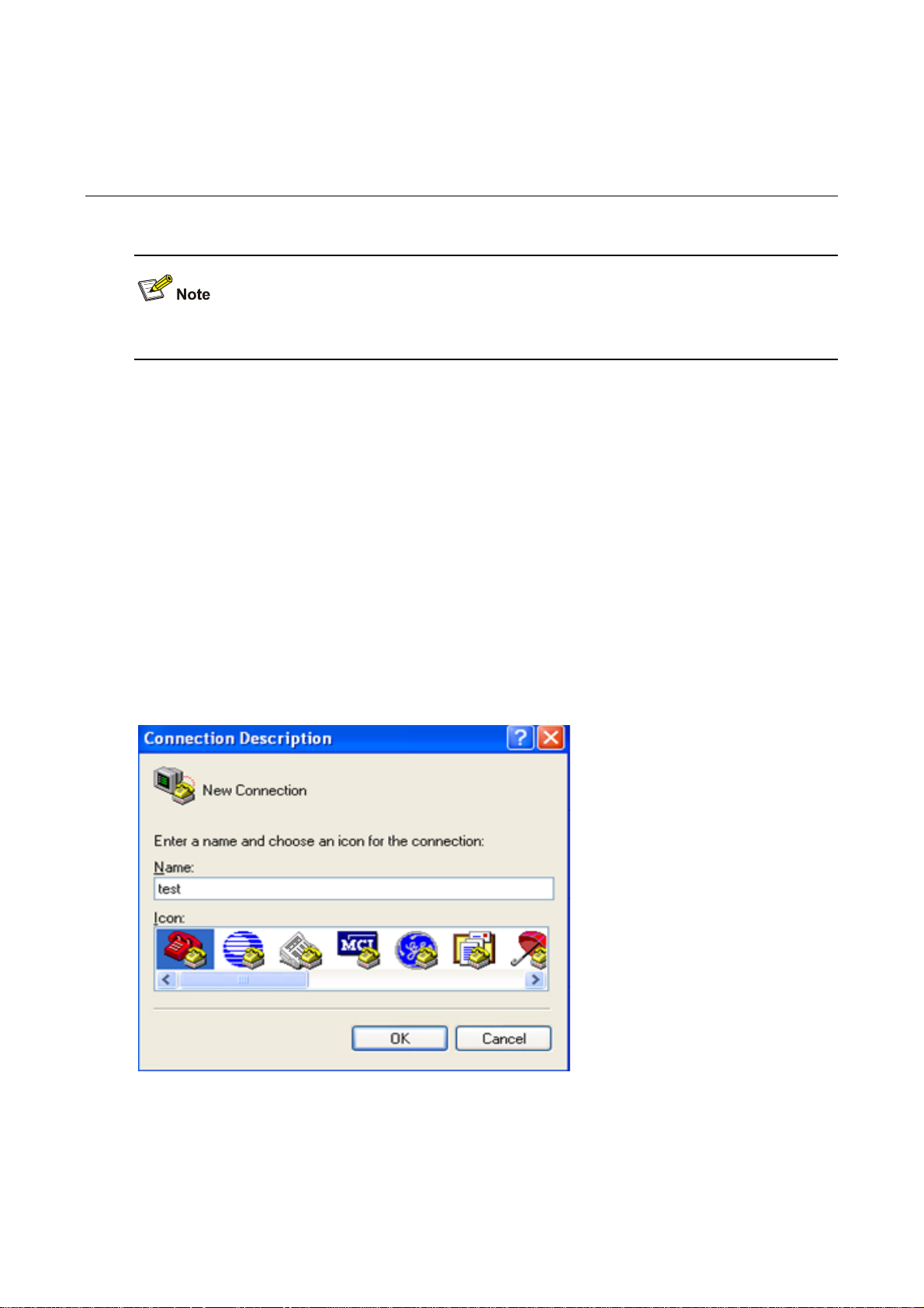
5 Starting and Configuring the Firewall
You can only use the console port to make initial configuration of the firewall.
Setting up a Configuration Environment
Connecting the Firewall to a Configuration Terminal
For the connection of the firewall to the configuration terminal, refer to “Connecting the Console Cable”
in Chapter 4 “Installing the Firewall”.
Setting the Parameters for the Configuration Terminal
Step1 Create a HyperTerminal connection. Select Start > Programs > Accessories > Communications >
HyperTerminal, and enter a connection name in the Connection Description dialog box, as shown in
Figure 5-1.
Figure 5-1 Create a connection
Step2 Select a connection port. Select a serial port from the Connect using drop-down list in the Connect To
dialog box as shown below. Be sure to select the serial port to which the console cable is actually
connected.
5-1
Page 67

Figure 5-2 Select a port for local configuration connection
Step3 Set serial port parameters
Figure 5-3 Set serial port parameters
Set the properties of the serial port in the COM1 Properties dialog box, as shown in
5-2
Table 5-1.
Page 68

Table 5-1 Set serial port parameters
Item Value
Bits per second 9600 bps (default)
Data bits 8
Parity None
Stop bits 1
Flow control None
In case SecureCRT is used to configure the F5000-A5 firewall, flow control of the serial port must be
set to Xon/Xoff; otherwise, the terminal screen displays nothing or only illegible characters.
To use the default settings, click Restore Defaults.
Step4 Click OK after setting the serial port parameters to enter the HyperTerminal window , as shown in
5-4.
Figure 5-4 HyperTerminal window
Figure
Step5 Set HyperTerminal properties. In the HyperTerminal window, select File > Properties from the menu,
and select the Settings tab to enter the properties setting dialog box, as shown in
Figure 5-5. Select
VT100 or Auto detect, and click OK to return to the HyperTerminal window.
5-3
Page 69

Figure 5-5 Set HyperTerminal properties
Firewall Power-on
Checklist for Firewall Power-on
Before powering on the firewall, check that:
z The power cord and ground cable are correctly connected.
z The voltage of the power source conforms to voltage requirements of the firewall.
z The console cable is correctly connected. The configuration terminal or PC is powered on and the
emulation program is properly configured.
z If an external CF card is needed to store applications, the CF card is properly installed.
Before powering on the firewall, locate the power switch so that you can disconnect the power supply in
time in case of an emergency.
5-4
Page 70

Powering on the Firewall
z Turn on the power source.
z Turn on the power switch on the power module of the firewall.
Checklist/Operations after Power-on
After powering on the firewall, check that:
1) The LEDs on the MPU are normal. For the status of the LEDs, refer to “Table 1-2 Description of the
device state LEDs” in Chapter 1 “Firewall Overview”.
2) The ventilation system works normally. You can hear that the fans are working.
3) The configuration terminal displays information normally. You can see the startup window on the
local configuration terminal. For more information, refer to “
4) After com pleting the power-on self-test (P OST), the system prompts you to press Enter. When the
command line prompt appears, you can proceed to configure the firewall.
Startup Process
After power-on, the firewall initializes its memory, and then runs the extended BootWare. The f ollowi ng
information appears on the terminal screen:
Startup Process” on page 5-5.
System start booting...
Booting Normal Extend BootWare....
*************************************************************************
* *
* H3C SecPath F5000-A BootWare, Version 1.00 *
* *
*************************************************************************
Copyright (c) 2004-2008 Hangzhou H3C Technologies Co., Ltd.
Compiled Date : May 06 2008
CPU Type : XLR732
CPU L1 Cache : 32KB
CPU Clock Speed : 1000MHz
Memory Type : DDR2 SDRAM
Memory Size : 2048MB
Memory Speed : 533MHz
BootWare Size : 1536KB
Flash Size : 4MB
cfa0 Size : 247MB
CPLD Version : 131.0
PCB Version : Ver.A
BootWare Validating
Press Ctrl+B to enter extended boot menu...
5-5
Page 71

Press Ctrl+B at this prompt to enter the extended Boot menu; otherwise, the sy st em st art s to read a nd
decompress the application program.
z To enter the extended Boot menu, press Ctrl+B within four seconds as the sy stem displays “Press
Ctrl+B to enter extended boot menu”. Otherwise, the system reads and decompresses the
application program.
z If you want to enter the extended Boot menu after the system starts decompression, you need to
restart the firewall.
z For convenience of reading and understanding, the extended Boot menu i s referred to as the main
BootWare menu unless otherwise described.
Starting to get the main application file--cfa0:/main.bin!..................
......................................................
The main application file is self-decompressing
..........................................................................
..........................................................................
.......
.......
Done!
System is starting.....
User interface con0 is available.
Press ENTER to get started.
Press Enter and the system displays:
<H3C>
This prompt indicates that the firewall has entered user view and is ready for configuration.
Configuration Fundamentals
In general, the configuration steps are as follows:
Step1 Before configuring the firewall, you should summarize the networking requirements, including the
networking objective, role of the firewall in the network, division of subnets, W AN type and transmission
medium, network security policy and network reliability.
Step2 Based on the above requirements, draw a clear, complete network diagram.
Step3 Configure the WAN interface of the firewall and the operating parameters of the interface according to
the WAN transmission medium.
Step4 Configure IP addresses of interfaces on the firewall according to the division of the subnets.
Step5 Configure routes. If it is necessary to enable a dynamic routing protocol, configure related operating
parameters of the protocol.
Step6 Perform special security configuration for the firewall if necessary.
5-6
Page 72

Step7 Perform reliability configuration for the firewall if necessary.
For the configuration details of the protocols or functions of the firewall, refer to H3C SecPath Series
Security Products User Manual.
Command Line Interface
Features of the Command Line Interface
The command line interface (CLI) of the firewall enables you to configure, manage, and maintain the
firewall.
The CLI provides the following functions:
z Allows you to perform local configuration through the console port.
z Allows you to perform local or remote configuration and directly log into and manage other device s
by using the telnet command.
z Provides online help information that is available by entering “?”.
z Provides network diagnostic tools, such as Tracert and Ping, for quick diagnosis of network
connectivity.
z Provides all kinds of detailed debugging information to help diagnose network faults.
z Supports the auto-complete function. If you enter a conflict-free part of a command, the command
will be interpreted. For example, you just need to enter dis for display.
z Supports the suggest function. For example, if you type dis and press Tab, all commands start ing
with dis will be displayed.
Command Line Interface
The command line interface of the firewall provides plenty of configuration commands. All the
commands are grouped in system view. Each group corresponds to a view. You can switch between
different configuration views by using corresponding commands. In general, only certain commands
can be executed in a particular view. However, some commonly used commands, such as ping and
display current-configuration, can be executed in any view.
5-7
Page 73

Table of Contents
6 Maintaining Software·································································································································6-1
Overview·················································································································································6-1
Files·················································································································································6-1
BootWare Program File···················································································································6-1
Application Files ······························································································································6-1
Configuration Files···························································································································6-2
Software Maintenance Methods······································································································6-3
BootWare Menu······································································································································6-5
Main Menu·······································································································································6-5
Serial Submenu·······························································································································6-7
Ethernet Submenu···························································································································6-8
File Control Submenu······················································································································6-9
BootWare Operation Submenu·······································································································6-9
Storage Device Operation Submenu·····························································································6-10
Upgrading BootWare and Applications Through a Serial Port······························································6-10
Introduction to Xmodem················································································································6-10
Modifying Serial Port Parameters··································································································6-11
Upgrading an Application ··············································································································6-13
Upgrading BootWare·····················································································································6-14
Upgrading BootWare and Applications Using TFTP·············································································6-16
Upgrading an Application Using TFTP on the BootWare Menu····················································6-17
Upgrading and Backing Up an Application Using TFTP at the CLI···············································6-20
Upgrading BootWare and Applications Using FTP···············································································6-22
Upgrading an Application Using FTP on the BootWare Menu······················································6-22
Upgrading and Backing Up an Application Using FTP at the CLI·················································6-24
Maintaining Application and Configuration Files···················································································6-29
Displaying All Files ························································································································6-29
Setting Application Files Attributes································································································6-30
Deleting a File································································································································6-32
Dealing with Password Loss·················································································································6-33
BootWare Password Loss·············································································································6-33
Dealing With User Password Loss································································································6-34
Dealing With Super Password Loss······························································································6-35
Backing Up and Restoring BootWare···································································································6-35
Backing Up the Entire BootWare···································································································6-36
Restoring the Entire BootWare······································································································6-36
i
Page 74

6 Maintaining Software
Overview
Files
Three types of files need to be managed on the firewall:
z BootWare program file
z Application file
z Configuration file
BootWare Program File
The BootWare program file is used for booting the application program when the firewall starts and is
stored in the flash memory. The entire BootWare program consists of a basic section and an extended
section.
z The basic section is used for the basic initialization of the system.
z The extended section provides abundant human-computer interactio n (HCI) functions an d is used
to initialize interfaces and upgrade the application program and the boot system.
z The entire BootWare program is the combination of the basic section and the extended section.
After the basic section is loaded, you can load and upgrade the extended section on the menu of
the basic section.
Application Files
The firewall supports the dual image function. By default, the system defines three types of application
files for boot.
z Main application file (with the attribute of M)
z Backup application file (with the attribute of B)
z Secure application file (with the attribute of S)
These three types of application files are stored in a CF card.
By default, they are written into the built-in CF card before delivery.
If you have uploaded all the three types of application files into the built-in CF card, the system will b oot
using these three files in the M-B-S order. For information about attribute and boot order modifications
for application files, refer to "
Maintaining Application and Configuration Files” on page 6-29.
The following gives the default names of the application files and their priorities for system boot.
z Main application file. The default name is main.bin. It is the default application file used for system
boot.
z Backup application file. The default name is backup.bin. When booting with the main application
file fails, the system uses the backup application file for startup.
z Secure application file. The default name is secure.bin. When booting with the main and backup
application files fails, the system uses the secure application file for startup. If booting with the
secure application file fails, the system displays a boot failure.
6-1
Page 75

Note that:
z An application file with the attribute of M, B, or S can be used for system startup, but one with an
attribute of N/A (that is, an application file without a specific attribute assigned to it) cannot.
z You can modify the names of application files at the CLI after the application program is started.
z You can modify the attributes of application files on the BootWare menu or the CLI after the
application program is started. Because the secure application file is the last resort for system boot,
you cannot change its attribute or turn another type of application file into a secure application file
by means of attribute modification. You can only download it on the BootWare menu.
z An application file can have different attributes assigned, but only one file of the same type (M, B, or
S) can exist in the CF card at a time. For instance, if a file in the CF card has both M and B attributes,
no other file with the attribute of M or B can exist in the CF card. If the attribute of another file is
changed from N/A to B, the existing file that has both M and B attributes will lose its B attribute.
Configuration Files
The configuration files are used to store the configuration information of the firewall and load the
configuration information at system boot.
1) A system that supports the main and backup attributes of configuration files defines three types of
configuration files by default:
z Main configuration file (with the attribute of M)
z Backup configuration file (with the attribute of B)
z Secure configuration file (with the attribute of S)
The main and backup configuration files are mainly used as follows:
z When the main configuration file is damaged or lost, the backup configuration file is used to load
the configuration information. This double protection mechanism enhances the security and
reliability of the file system.
z When saving the current configuration file, you can specify its attribute as main or backup. If no
attribute is specified, N/A is used for the configuration file.
z You can select to delete the main or backup configuration file. For a configuration file with both M
and B attributes, you can select to remove its M or B attribute.
z You can define a configuration file as the one to be used at the next boot by changing its attribut e to
M.
The secure configuration file is used when the system fails to boot using the main, and then the backup
configuration file.
2) A system that does not support the main and backup attributes of configuration files define only one
type of configuration file, denoted by N/A.
The configuration files have a file name extension of .cfg.
By default, they are written into the built-in CF card before delivery.
Y ou can configure the system to support the main and backu p attributes of configuration files as needed.
However, after doing that, you cannot restore the single type configuration file mode.
The system will select a configuration file as follows:
1) If the system supports the main and backup attributes of configuration files, the system:
z Uses the main configuration file to initialize the configuration if the main file exists.
z Uses the backup configuration file to initialize the configuration if the main file does not exist.
z Uses default settings for initialization if the backup file does not exist either.
2) If the system does not support the main and backup attributes of configuration files, the system:
6-2
Page 76

z Uses the default configuration file (if any) to initialize the configuration. The default configuration file
is startup.cfg. Note that you can use the startup saved-configuration cfgfile command to define
the configuration file to be used at the next system boot.
z Uses the default settings if the default configuration file does not exist.
Note that:
z The F5000-A5 does not support the main and backup attributes of configuration files.
z You can rename the configuration files at the CLI after the application program is started.
z A configuration file name cannot be longer than 64 characters, including a drive letter and a string
terminator. For instance, if the drive letter is “cfa0:/”, the file name without the drive letter and st ring
terminator can be at most [ 64 – 1 – 6 ] = 57 characters in length.
z If the file name with the drive identifier and string terminator excluded contains more than 57
characters, errors will occur in file operation. Typically, a file name with the driver identifier and
string terminator excluded is recommended to contain no more than 16 characters.
z At BootWare boot, the names of the configuration files will be displayed, but the types will still be
displayed as N/A.
z For details about the startup saved-configuration cfgfile command, refer to H3C SecPath Series
Security Products User Manual.
Software Maintenance Methods
You can maintain the firewall software in the following two ways:
z Upgrade BootWare and application programs using the Xmodem protocol through a serial port.
z Upgrade BootWare and application programs usi ng the FTP or TFTP protocol through an Ethernet
interface. This upgrade can be carried out on the BootWare menu or at the CLI.
Note that:
z When upgrading an application file, if you select to overwrite the existing application file, make sure
the power supply works normally during the upgrade process. Otherwise, the application upgrade
will fail and the existing application file will be damaged. If the existing application file is the only
one for booting the system, the device will fail at the next reboot.
z When upgrading the basic BootWare section, make sure the power supply works normally during
the upgrade process. Otherwise, the basic BootWare section will be damaged, resulting in failure
of device reboot.
z If upgrading the extended BootWare section fails, you can upgrade it again.
6-3
Page 77
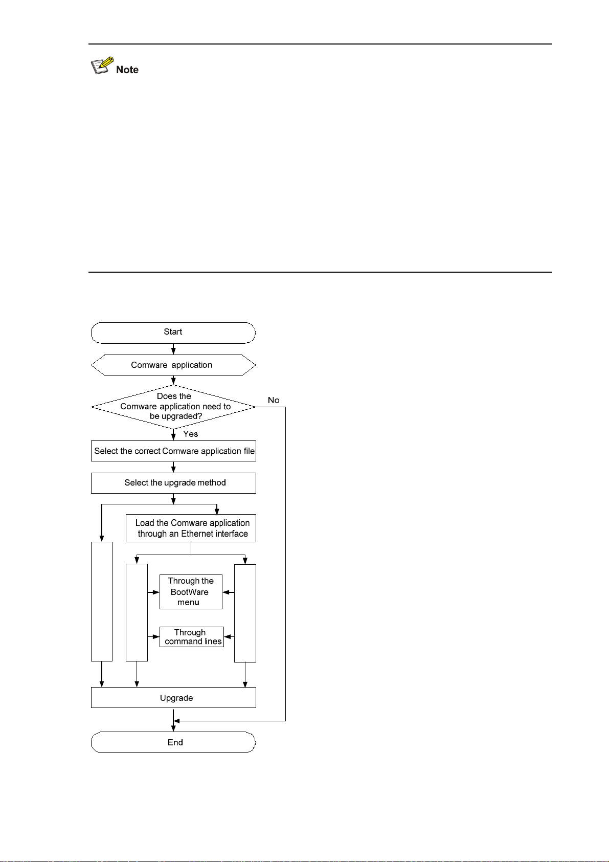
z The BootWare program is upgraded together with the Comware application program. You do not
need to upgrade the BootWare program separately. After you upgrade the Comware application
program to the latest version and restart the device, the system checks whether the current
BootWare version is consistent with the one in the host application. If not, the system automatically
upgrades the BootWare program.
z When a service card is started up, it automatically checks the current BootWare version. If the
BootWare version bound to the Comware application program is different from the current
BootWare version, the system upgrades the current BootWare version automatically.
z To use correct files for upgrading, check the current versions of the BootWare and Comware
application programs. For associations between Comware versions and BootWare versions, refer
to the hardware and software compatibility matrix in Release Notes.
Figure 6-1 BootWare and Comware upgrade flow
Using Xmodem
Using TFTP
Usi n g FTP
6-4
Page 78

BootWare Menu
Main Menu
When the firewall is powered on, it first runs the basic segment and then the extended segment of
BootWare. The followin g informatio n is displayed on the configuration terminal:
System start booting...
Booting Normal Extend BootWare....
*************************************************************************
* *
* H3C SecPath F5000-A BootWare, Version 1.00 *
* *
*************************************************************************
Copyright (c) 2004-2008 Hangzhou H3C Technologies Co., Ltd.
Compiled Date : May 06 2008
CPU Type : XLR732
CPU L1 Cache : 32KB
CPU Clock Speed : 1000MHz
Memory Type : DDR2 SDRAM
Memory Size : 2048MB
Memory Speed : 533MHz
BootWare Size : 1536KB
Flash Size : 4MB
cfa0 Size : 247MB
CPLD Version : 131.0
PCB Version : Ver.A
BootWare Validating
Press Ctrl+B to enter extended boot menu...
Starting to get the main application file--cfa0:/main.bin!...............
..........................................................................
..................................................................
The main application file is self-decompressing
Press Ctrl + B to enter the extended BootWare menu or let the system start to read and decompress
the main application file.
6-5
Page 79

z To enter the extended BootWare menu, press Ctrl+B within fou r seconds after th e system displays
“Press Ctrl+B to enter extended boot menu”. Otherwise, the system reads and decompresses the
main application file.
z If you want to enter the extended BootWare menu after the system starts main application file
decompression, you need to restart the firewall.
z For convenience, the extended BootWare menu is referred to as the main BootWare menu unless
otherwise specified.
Press Ctrl + B when “Press Ctrl+B to enter extended boot menu...” appears, and then the system
displays:
Please input BootWare password:
After you type the correct BootWare password, the system will display the BootWare menu, which
provides:
z The name of the operating device.
z A Storage Device Operation option for you to select the storage device from which you are going to
loading the application file.
Note that:
z The initial BootWare password is null.
z You have three chances to enter the correct BootWare password. If you fail to enter the correct
password for three times, the system will be halted and you n eed to restart the fi rewall to ente r the
correct password.
z You can enter the main menu only after you enter the correct BootWare password.
Note: The current operating device is cfa0
Enter < Storage Device Operation > to select device.
========================<EXTEND-BOOTWARE MENU>========================
|<1> Boot System |
|<2> Enter Serial SubMenu |
|<3> Enter Ethernet SubMenu |
|<4> File Control |
|<5> Modify BootWare Password |
|<6> Skip Current System Configuration |
|<7> BootWare Operation Menu |
|<8> Clear Super Password |
|<9> Storage Device Operation |
|<0> Reboot |
======================================================================
Enter your choice(0-9):
Table 6-1 gives a detailed description of the menu.
6-6
Page 80

Table 6-1 BootWare main menu
Menu item Description
<1> Boot System Load and boot system applications from a CF card.
Enter the serial port submenu.
<2> Enter Serial SubMenu
For detailed description of this submenu, refer to “
Submenu“ on page
6-7.
Enter the Ethernet submenu.
<3> Enter Ethernet SubMenu
For detailed description of this submenu, refer to “
Submenu” on page
6-8.
Enter file control submenu.
<4> File Control
<5> Modify BootWare
Password
For detailed description of this submenu, refer to “
Submenu” on page
Modify the BootWare password.
6-9.
Skip current system configuration.
<6> Skip Current System
Configuration
This operation takes effect only once.
This operation is generally used when you lose the password.
<7> BootWare Operation
Menu
Enter BootWare operation submenu
For detailed description of this submenu, refer to “
Operation Submenu“ on page
6-9.
Serial
Ethernet
File Control
BootWare
Clear the super password.
The super password is used in user level switching.
<8> Clear Super Password
No super password is set by default.
This setting is valid for the first reboot of the firewall only. The
super password will be restored after a second reboot.
Enter the storage device operation menu.
<9> Storage Device Operation
<0> Reboot Reboot the firewall.
This operation allows you to select a storage medium in which the
application will be used to boot the system.
z In the firewall, the built-in CF card is identified with cfa0, while the external CF card is identified with
cfb0.
z If an application file is stored in the external CF card, you need to select 9 on the main BootWare
menu and then choose to load the application from cfb0.
Serial Submenu
Select 2 on the main menu to enter the serial submen u, where you can upgrade application files and the
BootWare program through Xmodem.
The system displays:
=========================<Enter Serial SubMenu>=======================
6-7
Page 81

|Note:the operating device is cfa0 |
| <1> Download Application Program To SDRAM And Run |
| <2> Update Main Application File |
| <3> Update Backup Application File |
| <4> Update Secure Application File |
| <5> Modify Serial Interface Parameter |
| <0> Exit To Main Menu |
======================================================================
Enter your choice(0-5):
Items on this submenu are described in Table 6-2.
Table 6-2 BootWare serial submenu
Menu item Description
<1> Download Application Program To SDRAM
And Run
<2> Update Main Application File Upgrade the main application file
<3> Update Backup Application File Upgrade the backup application file
<4> Update Secure Application File Upgrade the secure application file
<5> Modify Serial Interface Parameter Modify serial port parameters
<0> Exit To Main Menu Return to the main menu
Ethernet Submenu
Select 3 on the main menu to enter the Ethernet submenu, where you can upgra de application files and
the BootWare program through FTP or TFTP.
The system displays:
=========================<Enter Ethernet SubMenu>=====================
|Note:the operating device is cfa0 |
| <1> Download Application Program To SDRAM And Run |
| <2> Update Main Application File |
| <3> Update Backup Application File |
| <4> Update Secure Application File |
| <5> Modify Ethernet Parameter |
| <0> Exit To Main Menu |
| < Ensure The Parameter Be Modified Before Downloading! > |
======================================================================
Enter your choice(0-5):
Download an application to SDRAM through the
serial port and run the program.
Items on this submenu are described in Table 6-3.
Table 6-3 Ethernet submenu
Menu item Description
<1> Download Application Program To SDRAM
And Run
Download an application to SDRAM and run
the program.
<2> Update Main Application File Upgrade the main application file
6-8
Page 82

Menu item Description
<3> Update Backup Application File Upgrade the backup application file
<4> Update Secure Application File Upgrade the secure application file
<5> Modify Ethernet Parameter Modify Ethernet interface parameters
<0> Exit To Main Menu Return to the main menu
File Control Submenu
Select 4 on the main menu to enter the file control submenu, where you can view, modify, or delete
application files.
The system displays:
==============================<File CONTROL>==========================
|Note:the operating device is cfa0 |
| <1> Display All File(s) |
| <2> Set Application File type |
| <3> Delete File |
| <0> Exit To Main Menu |
======================================================================
Enter your choice(0-3):
Items on this submenu are described in Table 6-4.
Table 6-4 File control submenu
Menu item Description
<1> Display All File(s) Display all files.
<2> Set Application File type Set the application file type.
<3> Delete File Delete a file.
<0> Exit To Main Menu Return to the main menu.
BootWare Operation Submenu
Select 7 on the main menu to enter the BootWare operation subme nu:
========================<BOOTWARE Operation Menu>=====================
|Note:the operating device is cfa0 |
| <1> Backup Full BootWare |
| <2> Restore Full BootWare |
| <3> Update BootWare By Serial |
| <4> Update BootWare By Ethernet |
| <0> Exit To Main Menu |
======================================================================
Enter your choice(0-4):
Items on this submenu are described in Table 6-5.
6-9
Page 83

Table 6-5 BootWare operation submenu
Menu item Description
<1> Backup Full BootWare Back up the entire BootWare.
<2> Restore Full BootWare Restore the entire BootWare.
<3> Update BootWare By Serial Upgrade BootWare through a serial port.
<4> Update BootWare By Ethernet Upgrade BootWare through an Ethernet interface.
<0> Exit To Main Menu Return to the main menu.
Storage Device Operation Submenu
Select 9 on the main menu to enter the storage device operation submenu:
==========================<DEVICE CONTROL>============================
|<1> Display All Available Nonvolatile Storage Device(s) |
|<2> Set The Operating Device |
|<3> Set The Default Boot Device |
|<0> Exit To Main Menu |
======================================================================
Enter your choice(0-3):
Items on this submenu are described in Table 6-6.
Table 6-6 Storage device operation submenu
Menu item Description
<1> Display All Available Nonvolatile Storage Device(s) Display all available storage devices.
<2> Set The Operating Device Configure the operating device.
<3> Set The Default Boot Device Configure the default boot device.
<0> Exit To Main Menu Return to the main menu.
Upgrading BootWare and Applications Through a Serial Port
Introduction to Xmodem
Xmodem is used for upgrading BootWa re and applications through a serial port.
Xmodem is a file transfer protocol that is widely used due to its simplicity and high performance.
Xmodem transfers files through a serial port. It support s two types of data packet s (128 bytes and 1 KB),
two check methods (checksum and CRC), and error packet retransmission mechanism (generally the
maximum number of retransmission attempts is 10).
An Xmodem transmission procedure is completed by the cooperation of a receiving program and a
sending program. The receiving program sends a negotiation character to negotiate a packet check
method. After the negotiation, the sending program starts to transmit data packets. Upon receiving a
complete data packet, the receiving program chec ks the packet using the agreed method.
z If the check succeeds, the receiving program sends an acknowledgement character and the
sending program proceeds to send another packet.
6-10
Page 84

z If the check fails, the receiving program sends a negative acknowledgement character and the
sending program retransmits the packet.
Modifying Serial Port Parameters
In actual applications, you may need to make the serial port baud rate higher to reduce upgrading time
or make it lower to guarantee transmission reliability. This section introduces how to adjust the serial
port baud rate.
Step1 Enter the main menu and select 2 to enter the serial submenu, and then select 5 to modify the baud rate.
The system displays the following:
============================<BAUDRATE SET>============================
|Note:'*'indicates the current baudrate |
| Change The HyperTerminal's Baudrate Accordingly |
|-----------------------<Baudrate Available>-------------------------|
|<1> 9600(Default) * |
|<2> 19200 |
|<3> 38400 |
|<4> 57600 |
|<5> 115200 |
|<0> Exit |
======================================================================
Enter your Choice(0-5):
Step2 Select a proper baud rate. For example, select 5 for a baud rate of 115200 bps and the system displays:
Baudrate has been changed to 115200 bps.
Please change the terminal's baudrate to 115200 bps, press ENTER when ready.
At this time, the baud rate of the serial port of the firewall is 11520 0 bps, while that of the terminal is still
9600 bps. The firewall and the terminal cannot communicate with each other with different baud rates.
Therefore, you need to make the baud rate on the terminal consistent with that on the firewall.
Step3 Perform the following operations on the terminal:
Figure 6-2 Disconnect the terminal
Step4 Select File > Properties, and then click Configure… to change the bits per second to 115200.
6-11
Page 85

Figure 6-3 Modify the baud rate on the terminal
Step5 Select Call > Call to establish a new connection.
Figure 6-4 Establish a new connection
Step6 Press Enter on the console terminal. The system displays the current baud rate and returns to the
previous menu.
The system displays:
The current baudrate is 115200 bps
After downloading files with a changed baud rate, you need to restore the baud rate on the
HyperTerminal to 9600 bps to ensure normal display on the console screen when the system boots or
reboots.
6-12
Page 86

Upgrading an Application
The application upgrading on a serial port is implemented on the serial submenu.
Step1 Select 2 on the main menu to enter the serial submenu. For details about this submenu, refer to “
Submenu” on page
6-7.
The following example shows how to upgrade the main application file main.bin:
To accelerate the upgrading speed, you can modify the serial port baud rate before upgrading the main
application file. For details, refer to “
Modifying Serial Port Parameters” on page 6-11.
Step2 Select 2 on the serial submenu. The system displays:
Please Start To Transfer File, Press <Ctrl+C> To Exit.
Waiting...CCCCCCCCCCCCCCCCCCCC
Step3 Select Transfer > Send file… in the terminal window. The following dialog appears:
Figure 6-5 Send file dialog box
Serial
Step4 Click Browse… to select the application file to be downloaded, select Xmodem from the Protocol
drop-down list, and click Send. The following dialog box appears:
Figure 6-6 Sending file dialog box
After the application file is downloaded, the following information appears on terminal interface,
indicating a successful upgrade.
6-13
Page 87

Download successfully!
14092032 bytes downloaded!
The system then prompts you to enter the target file name.
Input the File Name:
Step5 Input the file name.
1) If the file name is different from that of any existing file in the storage medium, the application file is
saved using the specified file name, for example,
Input the File Name:main.bin
Updating File cfa0:/main.bin......... ..........................
........................................................................................
........................................................................................
.........................................Done!
After that, you need to return to the main menu, enter the file control submenu, and set this application
file as the default boot program. The system will use this program at next system reboot. For description
of the default boot program, refer to “
2) If the file name already exists in the storage medium, the system displays:
The file is exist,will you recover it? [Y/N]
Setting Application Files Attributes” on page 6-30.
z Enter Y to overwrite the existing application file and complete the upgra ding operation. The system
uses the new application file at next system reboot.
z Enter N and the system displays:
Cancel to overwrite the file.
Failed!
As a result, the existing application file is not overwritten and the upgrading operation fails.
The size of an application is often over 10 MB. Even if the baud rate is 115200 bps, it takes about 30
minutes to upgrade the application through a serial port. Therefore, you are recommended to upgrade
an application through Ethernet.
Upgrading BootWare
To upgrade the BootWare, follow these steps:
Step1 Enter the main BootWare menu (refer to “
Main Menu” on page 6-5).
Step2 Select 7 to enter the BootWare operation submenu, where you can perform all BootWare operations.
For detailed description, refer to “
BootWare Operation Submenu” on page 6-9.
The following example shows how to upgrade the entire BootWare.
You need to upgrade the basic segment and then the extended segment to upgrade the BootWare.
Step3 Select 3 on the BootWare operation submenu. The system displays:
=================<BOOTWARE OPERATION SERIAL SUB-MENU>================
|<1> Update Full BootWare |
|<2> Update Extend BootWare |
6-14
Page 88

|<3> Update Basic BootWare |
|<4> Modify Serial Interface Parameter |
|<0> Exit To Main Menu |
=====================================================================
Enter your choice(0-4):
To accelerate the upgrade speed, you need to modify the serial port baud rate.
Step4 Select 4 to modify the serial baud rate to 115200 bps. To ensure communication between the device
and the terminal, you need to make the baud rate of the terminal consistent with that of the serial port.
For the modification of the terminal baud rate, refer to “
Modifying Serial Port Parameters” on page 6-11.
Step5 After setting the baud rate, return to the BootWare operation submenu and select 1. The system
displays the following:
Waiting ...CCCCCCCCCCCCCCCCCCCCCCCCC...
Step6 Select Transfer > Send file… in the terminal window. The following dialog appears.
Figure 6-7 Send file dialog box
Step7 Click Browse… to specify the application file to be downloaded, select Xmodem from the Protocol
drop-down list, and click Send. The following dialog box appears:
Figure 6-8 Sending file dialog box
6-15
Page 89

After the application file is downloaded, the following information appears on terminal interface,
indicating a successful upgrade.
Download successfully!
14092032 bytes downloaded!
Updating Basic BootWare? [Y/N]
Step8 Upgrade the BootWare.
1) If you enter N, the system displays:
Not update the Basic!
Updating Extend BootWare? [Y/N]
The system stops upgrading the basic segment and asks you whether to upgrade the extended
segment or not.
2) If you enter Y, the system proceeds to upgrade the basic segment:
Updating Basic BootWare...............Done!
Updating Extend BootWare? [Y/N]Y
The system finishes upgrading the basic segment and asks you whether to upgrade the extended
segment or not.
z If you type N, the system does not upgrade the extended segment. In this case, the system only
has the basic segment upgraded.
z If you type Y, the system proceeds to upgrade the extended segment:
Updating Extend BootWare.................Done!
At this prompt, the extended segment is successfully upgraded.
By now, the entire BootWare has been successfully upgraded.
z The BootWare program is upgraded together with the Comware application. You do not need to
upgrade the BootWare separately. After the Comware is upgraded to the latest version, the system
automatically upgrades the BootWare when the system reboots.
z When a service card is started up, it automatically checks the current BootWare version. If the
BootWare version bound to the Comware application is different from the current BootWare
version, the system upgrades the current BootWare version automatically.
z The file name, size, and path in the above figures are for reference only. Check the current
BootWare and application versions before upgrading them.
Upgrading BootWare and Applications Using TFTP
If the application file is large, you can use TFTP to upgrade it to reduce upgrade time.
Trivial File Transfer Protocol (TFTP), a protocol in the TCP/IP suite, is used for file transfer between
client and server. It provides not-so-complex and low-cost file transfer services. TFTP provides
unreliable data transfer services over UDP and does not provide any access authorization and
authentication mechanism. It employs timeout and retransmission mechanisms to guarantee
successful data delivery.
6-16
Page 90

The firewall can serve as the TFTP client. The filer server serves as the TFTP server. You can
upload/download the application file on the firewall to/from the file server.
There are two approaches to upgrading BootWare and application files using TFTP:
z On the BootWare menu
z At the CLI
Upgrading an Application Using TFTP on the BootWare Menu
1) Set up a TFTP upgrading environment.
Figure 6-9 Set up a TFTP upgrading environment
z The firewall serves as the TFTP client and the PC serves as the TFTP server.
z Connect the management Ethernet port on the firewall to the PC using a crossover Ethernet cable.
Ensure the firewall and the PC are reachable to each other. Configure the IP address of the
management Ethernet port as 192.168.80.10 and that of the PC as 192.168.80.200.
z Start the TFTP server on the PC and set the path where the application file is stored.
6-17
Page 91

z The TFTP server is not provided with the device. You need to purchase and install it.
z You can upgrade applications and the BootWare through the console port or the management
Ethernet port.
2) Configure Ethernet port parameters on the BootWare menu.
Enter the main menu and select 3 to enter the Ethernet submenu. Select 5 to set the Ethernet port
parameters.
======================<ETHERNET PARAMETER SET>========================
|Note: '.' = Clear field. |
| '-' = Go to previous field. |
| Ctrl+D = Quit. |
======================================================================
Protocol (FTP or TFTP):tftp
Load File Name :main.bin
:main.bin
Target File Name :main.bin
:main.bin
Server IP Address :192.168.80.200
Local IP Address :192.168.80.10
Gateway IP Address :
FTP User Name :
FTP User Password :
Table 6-7 Command output description for setting Ethernet port parameters
Item Description
'.' = Clear field Shortcut key is to clear the current input.
'-' = Go to previous field Shortcut key is to return to the previous field.
Ctrl+D = Quit Shortcut key Ctrl + D is to quit the parameter setting page.
Protocol (FTP or TFTP) Choose to upgrade applications using FTP or TFTP.
Name of the download file, which needs to be the same as that of the
actual file to be downloaded.
At the same time, you need to set the download path on the
FTP/TFTP Client.
Load File Name
Note that:
z The first “main.bin“ is the previous file name automatically
remembered in the system.
z The second “main.bin“ is the file name set by the user.
z The file name with an extension, such as .bin, cannot contain
more that 50 characters.
6-18
Page 92

Item Description
Name of the target file after the file is downloaded to the firewall. The
extension of the target file needs to be the same as that of the
download file.
Target File Name
Note that:
z The first “main.bin“ is the previous file name automatically
remembered in the system.
z The second “main.bin“ is the file name set by the user.
Server IP Address IP address of the FTP/TFTP server
Local IP Address IP address of the interface connecting to the FTP/TFTP server.
Gateway IP Address IP address of the gateway. You need not configure this IP address.
FTP User Name
FTP User Password
FTP username, which will be used in FTP download. TFTP download
needs no username.
FTP password, which will be used in FTP download. TFTP download
needs no password.
z To use the default parameter after the colon, press Enter directly.
z If the Ethernet port parameter CRC appears faulty, the system modifies the parameters to the
default settings and displays “Check net params crc error, use the default value.”
3) After the configuration, the system automatically returns to the Ethernet submenu, where you can
select 2 to upgrade the main application file.
Loading.........
................
...... .... done
14092032 bytes downloaded!
Updating File cfa0:/main.bin
.........Done!
4) After the upgrading is finished, select 0 to return to the main menu and select 1 to reboot the
system from the CF card.
z If the input application file name already exists on the CF card, the system displays “The file is exist,
will you recover it? [Y/N]”. If you enter Y, the input application file overwrites the one in the CF card
and becomes the only application file of that type.
z Make sure the available space in the CF card is sufficient. Otherwise, the system displ ays “The free
space isn’t enough!”
z For detailed description of file types, refer to “Overview”.
6-19
Page 93
Upgrading and Backing Up an Application Using TFTP at the CLI
1) Set up a TFTP upgrading environment
z The firewall serves as the TFTP client and the PC serves as the TFTP server.
z For the procedures of setting up a upgrading environment, refer to “Upgrading an Application Using
TFTP on the BootWare Menu”.
z Run the terminal emulation program on the PC, and configure the IP addresses of the client and
server to be on the same subnet. Ensure the firewall and the PC a re reachable to each other. In this
example, configure the IP address of the management Ethernet port as 192.168.80.10 and that of
the PC as 192.168.80.200.
z You can use the ping command to verify the connectivity.
You can upgrade applications of the device through the console p ort or the management Ethernet port.
2) View the files in the storage medium and its available space.
To prepare for upgrading application files, use the dir command on the terminal to view the files stored
in the current file system and the available space of the storage device.
<H3C>dir
Directory of cfa0:/
0 drw- - Oct 28 2000 04:09:30 logfile
1 -rw- 24802996 Oct 21 2007 17:03:26 main.bin
2 -rw- 1355 Oct 04 2007 17:22:12 startup.cfg
3 -rw- 24802996 Sep 13 2037 13:21:20 backup.bin
505480 KB total (456576 KB free)
File system type of cfa0: FAT16
Table 6-8 Output description
Field Description
Directory of cfa0:/ Name of the existing directory
505480 KB total (456576 KB free) Used space of the CF card (available space)
File system type of cfa0: FAT16 File system type of the CF card
3) Upgrade an application
Using TFTP, you can download an application file from the server to the firewall and overwrite the
existing main application file to implement application upgrading. The upgraded application file takes
effect when the device reboots.
# Download the application file main.bin from the PC to the firewall.
<H3C> tftp 192.168.80.200 get main.bin main.bin
6-20
Page 94

The file main.bin exists. Overwrite it? [Y/N]:y
Verifying server file...
Deleting the old file, please wait...
File will be transferred in binary mode
Downloading file from remote TFTP server, please wait...|
TFTP: 14092032 bytes received in 907 second(s)
File downloaded successfully.
z When you download an application file, if a file with the same name exists on the firewall, the
system asks you whether to overwrite the existing file on your device. You need to enter Y for
confirmation.
z For details about the ftfp command, refer to H3C SecPath Series Security Products User Manual.
z You can upgrade a configuration file in the way you upgrade an application file. A configuratio n file
can be modified using a text editor. You can modify a configuration file and then download the
modified configuration file to the firewall to finish upgrading the configuration file. The modification
takes effect after the firewall reboots.
4) Backup an application file
Using TFTP, you can backup an application file by uploading it from the firewall to the PC.
# Upload file main.bin on the firewall to the PC and save it as main.bin.
<H3C> tftp 192.168.80.200 put main.bin main.bin
File will be transferred in binary mode
Sending file to remote TFTP server. Please wait...\
TFTP: 14092032 bytes sent in 32 second(s).
File uploaded successfully.
z When you backup an application file, if the file name already exists on the server, the system
overwrites the existing file without any prompt.
z For details about the ftfp command, refer to H3C SecPath Series Security Products User Manual.
z You can backup a configuration file in the way you backup an application file.
6-21
Page 95

Table 6-9 Command output description for upgrading and backing up an a pplication file
Field Description
tftp 192.168.80.200 get main.bin main.bin
The file main.bin exists. Overwrite it? [Y/N]:
TFTP: 14092032 bytes received in 907
second(s)
Download the file to be upgraded from the
server.
Whether to overwrite the existing file with the
same name.
The file is downloaded and upgrading of the file is
successfully completed.
tftp 192.168.80.200 put main.bin main.bin Upload the file on the firewall to the server.
TFTP: 14092032 bytes sent in 32 second(s)
The file is uploaded and backup of the file is
successfully completed.
Upgrading BootWare and Applications Using FTP
If the application file is large, you can use FTP to downl oad it for upgrade, to reduce maintenance time.
As an application layer protocol, the File Transfe r Protocol (FTP) is mainly used to provide dat a transfer
between hosts. FTP provides reliable and connection-oriented data transfer service over TCP.
Compared with TFTP, the FTP software is much bigger.
There are two approaches to upgrading BootWare and application files using FTP:
z On the BootWare menu. In this approach, the firewall can serve as the FTP client only.
z At the CLI. In this approach, the firewall can serve as the FTP server or the FTP client.
Upgrading an Application Using FTP on the BootWare Menu
Set up an FTP upgrading environment.
6-22
Page 96

Figure 6-10 Set up an FTP upgrading environment
z The firewall serves as the FTP client and the PC serves as the FTP server.
z Connect the management Ethernet port on the firewall to the PC using a crossover Ethernet cable.
Ensure the connectivity between the firewall and the PC. In this example, configure the IP address
of the management Ethernet port as 192.168.80.10 while that of the PC as 192.168.80.200.
z Enable FTP server on the PC and set the path where the application file is stored. Set the FTP
username and password.
z The TFTP Server is not provided with the device. You need to purchase and install it.
z You can upgrade applications of the device through the con sole port or the m anage ment Ethernet
port.
For step 2 through step 4, refer to the corresponding steps in “
the BootWare Menu” on page
6-20.
Upgrading an Application Using TFTP on
6-23
Page 97

Upgrading and Backing Up an Application Using FTP at the CLI
Firewall serving as the FTP client and PC serving as the FTP server
1) Set up the upgrading environment. Refer to “Upgrading and Backing Up an Application Using
TFTP at the CLI” on page
2) Use the dir command on the terminal to view the files stored in the current file system and the
available space of the storage device. For details, refer to “
Application Using TFTP at the CLI” on page
3) Enable FTP server on the PC and set the path where the application file is stored. Set the FTP
username and password. In this example, the FTP username is guest and the password is
123456.
4) Log into the FTP server.
<H3C>ftp 192.168.80.200
Trying 192.168.80.200 ...
Press CTRL+K to abort
Connected to 192.168.80.200.
220 3Com 3CDaemon FTP Server Version 2.0
User(192.168.80.200:(none)):guest
331 User name ok, need password
Password:
230 User logged in
[ftp]
6-20.
Upgrading and Backing Up an
6-20.
After you log into the server, you can update and backup an application file using the CLI.
Table 6-10 Command output description for logging into the FTP server
Field Description
ftp 192.168.80.200 Log into the FTP server and enter FTP client view.
User(192.168.80.200:(none)) Input the username configured on the FTP server.
331 User name ok, need password Input the password.
230 User logged in You have logged into the FTP server successfully.
5) Upgrading an application file.
Using FTP, you can download an application file from the PC to the firewall, and overwrite the existing
main application file to implement application upgrading. The new application fil e t akes ef fect whe n the
firewall reboots.
# Download file main.bin from the FTP server to the firewall and save it using the same name of
main.bin.
[ftp]get main.bin main.bin
cfa0:/main.bin has been existing. Overwrite it? [Y/N]:y
227 Entering passive mode (192,168,80,200,7,237)
125 Using existing data connection
226 Closing data connection; File transfer successful.
FTP: 14092032 byte(s) received in 467.570 second(s), 53.00K byte(s)/sec.
6-24
Page 98

z When you download an application file, if a file with the same name exists on the firewall, the
system asks you whether to overwrite the existing file on your device. You need to enter Y for
confirmation.
z For details about the get command, refer to H3C SecPath Series Security Products User Manual.
z You can upgrade a configuration file in the way you upgrade an application file. A configuratio n file
can be modified using a text editor. You can modify a configuration file and then download the
modified configuration file to the firewall to upgrade the configuration file. The modification takes
effect after the firewall reboots.
6) Backup an application file.
Using FTP, you can backup an application file by uploading it from the firewall to the PC.
# Upload file main.bin on the firewall to the PC and save it as main.bin.
[ftp]put main.bin main.bin
227 Entering passive mode (192,168,80,200,5,34)
125 Using existing data connection
226 Closing data connection; File transfer successful.
FTP:14092032 byte(s) sent in 14.400 second(s), 1722.00Kbyte(s)/sec
[ftp]quit
221 Service closing control connection
z When you backup an application file, if the file name already exists on the server, the system
overwrites the existing file without any prompt.
z For details about the put command, refer to H3C SecPath Se ries Security P roducts User M anual.
z You can backup a configuration file in the way you backup an application file.
Table 6-11 Command output description for upgrading and backi ng up an application file
Field Description
[ftp]get main.bin main.bin Download the file used for upgrading.
cfa0:/main.bin has been existing. Overwrite it?
[Y/N]:y
FTP: 14092032 byte(s) received in 467.570
second(s), 53.00K byte(s)/sec
The system asks you whether to overwrite the
existing file.
Download and upgrading of the application file
is finished.
[ftp]put main.bin main.bin Upload the file from the firewall to the PC.
FTP: 14092032 byte(s) sent in 14.400 second(s),
1722.00Kbyte(s)/sec
6-25
Upload and backup of the application file is
finished.
Page 99

Field Description
[ftp]quit Quit FTP client view.
221 Service closing control connection Close the service control conne ction.
Firewall serving as the FTP client and PC serving as the FTP server
1) Set up an FTP upgrading environment.
Figure 6-11 Set up an FTP upgrading environment
Router
FTP Server
Ethernet
Cable
PC
FTP Client
CONSOLE
Cable
z Connect the management Ethernet interface on the firewall to the PC using a crossover Ethernet
cable.
z Configure the IP addresses of the server and the PC to be on the same network segment. Ensure
the connectivity between the router and the PC. In this example, the IP address of the management
Ethernet port is 192.168.80.10 and that of the PC is 192.168.80.200.
z You can use the ping command to verify the connectivity.
You can upgrade applications of the device through the console p ort or the management Ethernet port.
6-26
Page 100

2) Enable FTP server on the firewall.
# Enable FTP server.
[H3C] ftp server enable
# Add FTP username and password.
[H3C] local-user guest
New local user added.
[H3C-luser- guest] service-type ftp
[H3C-luser- guest] password simple 123456
[H3C-luser-guest] authorization-attribute level 3
Table 6-12 Output description
Field Description
ftp server enable Enable the FTP serve r.
local-user guest Create a local user, and enter user view.
service-type ftp Set the service type that can be used locally as FTP.
password simple 123456 Configure the user password.
authorization-attribute level 3 Set the user level to 3.
z The FTP service is enabled after the authentication and authorization of the FTP server are
configured. The FTP server supports multi-client access. A remote FTP client sends a request to
the FTP server. The FTP server executes an action accordingly and returns the e xecution result to
the client.
z After you configure FTP server authentication and authorization, you need to set the user level to 3.
Otherwise, when you store the backed-up file to the firewall, the system will display “You have no
rights to store files”. For configurations of user levels, refer to H3C SecPath Series Security
Products User Manual.
3) Enable the FTP client on the PC.
In the following example, the FTP client program is the built-in Windows XP FTP client:
Enter ftp in the DOS window:
C:\Documents and Settings\Administrator>ftp
ftp>
ftp> open 192.168.80.10
Connected to 192.168.80.10.
220 FTP service ready.
User (192.168.80.10:(none)): guest
331 Password required for guest
Password:
230 User logged in.
6-27
 Loading...