

Page 1

H3C SecPath F100-A Firewall
Installation Manual
Hangzhou H3C Technologies Co., Ltd.
http://www.h3c.com
Manual Version: T2-08044B-20070622-C-1.03
Page 2

Copyright © 2006-2007, Hangzhou H3C Te chnologie s Co., Ltd . and it s licen sors
All Rights Reserved
No part of this manual may be reproduced or transmitted in any form or by any means
without prior written consent of Hangzhou H3C Technologies Co., Ltd.
Trademarks
H3C, , Aolynk, , H3Care,
Neocean, NeoVTL, SecPro, SecPoint, SecEngine, SecPath, Comware, Secware,
Storware, NQA, VVG, V
HUASAN are trademarks of Hangzhou H3C Technologies Co., Ltd.
All other trademarks that may be mentioned in this manual are the property of their
respective owners.
Notice
The information in this document is subject to change without notice. Every effort has
been made in the preparation of this document to ensure accuracy of the content s, but
all statements, information, and recommendations in this document do not constitute
the warranty of any kind, express or implied.
To obtain the latest information, please access:
http://www. h3c.com
Technical Support
customer_service@h3c.com
http://www. h3c.com
, TOP G, , IRF, NetPilot,
2
G, VnG, PSPT, XGbus, N-Bus, TiGem, InnoVision and
Page 3

About This Manual
Related Documentation
In addition to this manual, each H3C SecPath Series Security Products documentation
set includes the following:
Manual Description
H3C SecPath Series Security Products
Operation Manual
H3C SecPath Series Security Products
Command Manual
It introduces the functional features,
principles and guide to configuration and
operation for H3C SecPath Series
Security Gateways/Firewalls.
It discusses all commands available in
the configuration and operation on H3C
SecPath Series Security
Gateways/Firewalls. The details include
command name, complete command
form, parameter, operation view, usage
description and configuration example.
Organization
H3C SecPath F100-A Firewall Installation Manual is organized as follows:
H3C SecPath Series Security Products
Web-Based Configuration Manual
Chapter Contents
Profiles the system characteristics and applications.
1 Product Overview
2 Installation Preparations
3 Firewall Installation
4 Firewall Configuration
Product appearance and system description are
also available in this chapter.
Focuses on environment requirements for system
installation, precautions before and during
installation. Installation tools are also listed in this
chapter.
Elaborates on mechanical installation, physical
connection of power cords, console cables and
Ethernet cables.
Presents fundamentals on system booting and
configuration.
It directs users to configure the H3C
SecPath Series Firewalls in Web mode.
5 Software Maintenance
Discusses system software maintenance, including
software upgrade and configuration file loading.
Page 4

Chapter Contents
Conventions
The manual uses the following conventions:
I. Command conventions
6 Troubleshooting
7 MIM Modules
Convention Description
Boldface
italic
[ ]
The keywords of a command line are in Boldface.
Command arguments are in italic.
Items (keywords or arguments) in square brackets [ ] are
optional.
Lists common system failures and specific locating
methods.
Details appearance, panel and LEDs of the
functional modules available on the H3C SecPath
F100-A, as well as module installation and
connection of interface cables.
{ x | y | ... }
[ x | y | ... ]
{ x | y | ... } *
[ x | y | ... ] *
&<1-n>
# A line starting with the # sign is comments.
Alternative items are grouped in braces and separated by
vertical bars. One is selected.
Optional alternative items are grouped in square brackets
and separated by vertical bars. One or none is selected.
Alternative items are grouped in braces and separated by
vertical bars. A minimum of one or a maximum of all can be
selected.
Optional alternative items are grouped in square brackets
and separated by vertical bars. Many or none can be
selected.
The argument(s) before the ampersand (&) sign can be
entered 1 to n times.
II. GUI conventions
Convention Description
< >
Button names are inside angle brackets. For example, click
<OK>.
[ ]
Window names, menu items, data table and field names
are inside square brackets. For example, pop up the [New
User] window.
Page 5
Convention Description
/
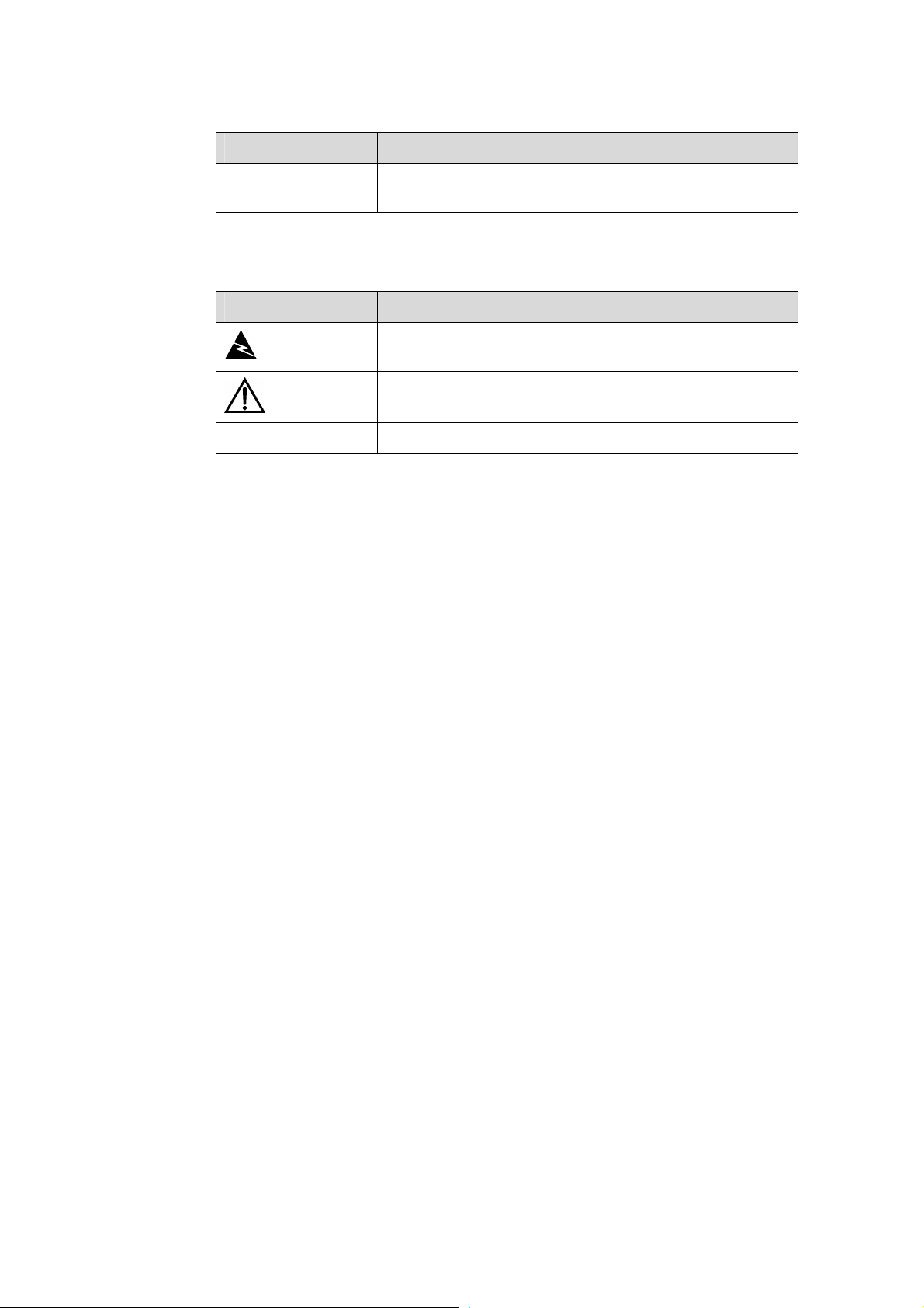
III. Symbols
Convention Description
Warning
Caution
Note Means a complementary description.
Environmental Protection
This product has been designed to comply with the requirements on environmental
protection. For the proper storage, use and disposal of this product, national laws and
regulations must be observed.
Multi-level menus are separated by forward slashes. For
example, [File/Create/Folder].
Means reader be extremely careful. Improper operation
may cause bodily injury.
Means reader be careful. Improper operation may cause
data loss or damage to equipment.
Page 6

Installation Manual
H3C SecPath F100-A Firewall Table of Contents
Table of Contents
Chapter 1 Product Overview........................................................................................................1-1
1.1 Overview ............................................................................................................................ 1-1
1.2 Hardware Features ............................................................................................................ 1-3
1.2.1 Appearance............................................................................................................. 1-3
1.2.2 System Specifications ............................................................................................. 1-3
1.2.3 LEDs........................................................................................................................ 1-4
1.2.4 Fixed Interface Attributes ........................................................................................ 1-5
Chapter 2 Installation Preparations............................................................................................. 2-1
2.1 General Site Requirements ............................................................................................... 2-1
2.1.1 Temperature and Humidity...................................................................................... 2-1
2.1.2 Cleanliness.............................................................................................................. 2-1
2.1.3 ESD Prevention....................................................................................................... 2-2
2.1.4 Electromagnetic Compatibility................................................................................. 2-2
2.1.5 Lightning Protection ................................................................................................ 2-3
2.1.6 Checking the Rack .................................................................................................. 2-3
2.2 Safety Precautions............................................................................................................. 2-3
2.3 Unpacking Inspections....................................................................................................... 2-4
2.4 Installation Tools, Meters and Equipment ......................................................................... 2-4
Chapter 3 Firewall Installation ..................................................................................................... 3-1
3.1 Installation Flow ................................................................................................................. 3-1
3.2 Mounting the Firewall......................................................................................................... 3-2
3.2.1 Free-Standing.......................................................................................................... 3-2
3.2.2 Rack-Mounting ........................................................................................................ 3-2
3.3 Connecting the PGND Wire............................................................................................... 3-3
3.4 Connecting to the Console Terminal ................................................................................. 3-4
3.5 Connecting to the Ethernet Interface................................................................................. 3-5
3.6 Connecting the Power Cord............................................................................................... 3-6
3.7 Verifying Installation........................................................................................................... 3-7
Chapter 4 Firewall Configuration................................................................................................. 4-1
4.1 Booting............................................................................................................................... 4-1
4.1.1 Setting Up a Configuration Environment................................................................. 4-1
4.1.2 Powering Up the Firewall ........................................................................................ 4-4
4.1.3 Booting Process ...................................................................................................... 4-5
4.2 Configuration Fundamentals.............................................................................................. 4-6
4.2.1 Basic Configuration Procedures.............................................................................. 4-6
4.2.2 Command Line Interface......................................................................................... 4-7
i
Page 7

Installation Manual
H3C SecPath F100-A Firewall Table of Contents
Chapter 5 Software Maintenance................................................................................................. 5-1
5.1 Boot Menu.......................................................................................................................... 5-1
5.2 Upgrading Application and Boot ROM Using XModem..................................................... 5-2
5.3 Backing Up and Restoring the Extended Segment of the Boot ROM ............................... 5-5
5.4 Upgrading the Application Program Using TFTP .............................................................. 5-6
5.5 Uploading/Downloading Applications/Files Using FTP...................................................... 5-8
5.6 Modifying Boot ROM Password....................................................................................... 5-12
5.7 Resetting a Lost Password .............................................................................................. 5-13
Chapter 6 Troubleshooting .......................................................................................................... 6-1
6.1 Troubleshooting PSU......................................................................................................... 6-1
6.2 Troubleshooting Configuration System ............................................................................. 6-1
6.3 Troubleshooting Application Upgrading............................................................................. 6-2
Chapter 7 MIM Modules................................................................................................................ 7-1
7.1 MIM Options....................................................................................................................... 7-1
7.2 Installing and Removing an MIM ....................................................................................... 7-1
7.3 Troubleshooting an MIM .................................................................................................... 7-3
7.4 1FE/2FE/4FE Module ........................................................................................................ 7-3
7.4.1 Introduction.............................................................................................................. 7-3
7.4.2 Appearance............................................................................................................. 7-3
7.4.3 Interface Attributes .................................................................................................. 7-4
7.4.4 Panel and Interface LEDs ....................................................................................... 7-5
7.4.5 Interface Cable........................................................................................................ 7-5
7.4.6 Connecting the Interface Cable............................................................................... 7-7
7.5 HNDE Module.................................................................................................................... 7-8
7.5.1 Introduction.............................................................................................................. 7-8
7.5.2 Interface Attributes .................................................................................................. 7-8
7.5.3 Panel and Interface LEDs ....................................................................................... 7-8
7.5.4 Troubleshooting the HNDE Module ........................................................................ 7-9
ii
Page 8

Installation Manual
H3C SecPath F100-A Firewall List of Figures
List of Figures
Figure 1-1 Front panel of the H3C SecPath F100-A firewall.................................................. 1-3
Figure 1-2 Rear panel of the H3C SecPath F100-A firewall .................................................. 1-3
Figure 3-1 Installation flow for the firewall.............................................................................. 3-1
Figure 3-2 Rack-mount the firewall ........................................................................................ 3-3
Figure 3-3 Console cable assembly....................................................................................... 3-4
Figure 3-4 Ethernet cable assembly ...................................................................................... 3-5
Figure 4-1 Local configuration through the console port ....................................................... 4-1
Figure 4-2 Create a new connection...................................................................................... 4-2
Figure 4-3 Select connection port.......................................................................................... 4-2
Figure 4-4 Define port parameters......................................................................................... 4-3
Figure 4-5 Select emulation type ........................................................................................... 4-4
Figure 5-1 Send File dialog box ............................................................................................. 5-3
Figure 5-2 Sending File interface........................................................................................... 5-4
Figure 5-3 Set up the local upload/download environment....................................................5-8
Figure 5-4 Set up the remote upload/download environment................................................ 5-9
Figure 7-1 Install the MIM I .................................................................................................... 7-2
Figure 7-2 Install the MIM II ................................................................................................... 7-2
Figure 7-3 1FE module ..........................................................................................................7-3
Figure 7-4 2FE module ..........................................................................................................7-4
Figure 7-5 4FE module ..........................................................................................................7-4
Figure 7-6 1FE module panel ................................................................................................7-5
Figure 7-7 2FE module panel ................................................................................................7-5
Figure 7-8 4FE module panel ................................................................................................7-5
Figure 7-9 Ethernet cable ...................................................................................................... 7-6
Figure 7-10 Category-5 twisted-pair cable............................................................................. 7-6
Figure 7-11 HNDE module panel ........................................................................................... 7-8
iii
Page 9

Installation Manual
H3C SecPath F100-A Firewall List of Tables
List of Tables
Table 1-1 Technical specifications of the H3C SecPath F100-A firewall................................ 1-3
Table 1-2 LEDs on the H3C SecPath F100-A firewall............................................................ 1-4
Table 1-3 Attributes of the console port.................................................................................. 1-5
Table 1-4 Attributes of the AUX port ....................................................................................... 1-5
Table 1-5 Attributes of the Ethernet interfaces ....................................................................... 1-5
Table 2-1 Temperature/humidity requirements in the equipment room.................................. 2-1
Table 2-2 Limits on the dust particles in the equipment room................................................ 2-1
Table 2-3 Harmful gas limits in the equipment room.............................................................. 2-2
Table 3-1 Physical dimensions of the H3C SecPath F100-A firewall..................................... 3-2
Table 7-1 Interface attributes of the 1FE, 2FE and 4FE modules .......................................... 7-4
Table 7-2 LEDs on the 1FE/2FE/4FE module ........................................................................7-5
Table 7-3 Straight-through cable pinout ................................................................................. 7-6
Table 7-4 Crossover cable pinout........................................................................................... 7-7
Table 7-5 Interface attributes of the HNDE module ............................................................... 7-8
Table 7-6 LEDs on the HNDE module.................................................................................... 7-9
iv
Page 10

Installation Manual
H3C SecPath F100-A Firewall Chapter 1
Chapter 1 Product Overview
1.1 Overview
H3C SecPath F100-A Firewall, developed by H3C Technologies, is a new-generation
firewall designed for enterprise users. It can work both as an egress firewall for small
and medium businesses and as an internal firewall for midsize enterprises.
H3C SecPath F100-A firewall provides four 10/100 Mbps autosensing LAN interfaces,
three 10/100 Mbps autosensing WAN interface and one MIM expansion slot which
supports multiple VPN access types and can accommodate the 1FE/2FE/4FE and
HNDE modules.
H3C SecPath F100-A firewall applies ASPF status detection technique to monitor
connection process and malicious commands and works together with access control
lists (ACLs) to implement dynamic packet filtering.
Product Overview
H3C SecPath F100-A firewall supports authentication, authorization, accounting (AAA ),
network address translation (NAT), hybrid mode, object oriented management, and
flow logging to ensure security and guaranteed services to the private networks
constructed on the open Internet.
H3C SecPath F100-A firewall supports multiple virtual private network (VPN) services,
such as layer 2 tunneling protocol (L2TP) VPN, IP security (IPsec) VPN, generic routing
encapsulation (GRE) VPN, and dynamic VPN, and allows users to build various VPNs,
like Internet, Intranet, and remote access VPNs using customized remote-user access
approaches, such as dial-up, leased line, Virtual LAN (VLAN), and tunneling.
H3C SecPath F100-A firewall provides basic routing features, including the routing
information protocol (RIP), open shortest path first (OSPF), routing policy, and policy
routing, as well as abundant QoS (quality of service) features, such as traffic policing,
traffic shaping, and multiple queue scheduling policies.
H3C SecPath F100-A firewall offers these main features:
I. IP VPN solution
Networks benefit enterprises in many ways; company headquarters can send important
information to its branch offices quickly and conveniently. To interconnect the intranets
of a company over the Internet, however, you need VPN technologies. The H3C
SecPath F100-A firewall provides abundant IP VPN services: L2TP and GRE provide
Layer 2 and Layer 3 tunneling respectively; IPsec provides tunnels encapsulated with a
security protocol.
1-1
Page 11

Installation Manual
H3C SecPath F100-A Firewall Chapter 1
II. Data security and reliability
The H3C SecPath F100-A firewall offers:
z High network security. ACL-based packet filtering detects data packet at the
network and transport layers to prevent illegal intrusion. Application specific
packet filter (ASPF) detects information about the application layer protocols and
monitors traffic at the application layer.
z NAT. Other than the basic functions, the NAT also can limit the number of
concurrent connections for an individual user. This eliminates the malicious
resource seizures without any negative impact on general network applications. In
addition, its enhanced NAT application layer gateway (ALG) function provides NAT
traversal for H.323, FTP, ICMP, and so on.
z AAA and RADIUS user authentication
z VPN (including GRE, L2TP, and MPLS) with the IPsec and IKE technologies to
guarantee the security of private networks over the Internet.
z OSPF and RIP2 to offer MD5 authentication and guarantee reliable exchange of
routing information.
z Virtual router redundancy protocol (VRRP) to provide communication line or
equipment backup in case of failure. This effectively enhances network
robustness and reliability.
z Deeper application recognition (DAR) to recognize and classify packets more
deeply, enhancing the control over data flows.
z Active/standby switchover to protect current services against interruption,
eliminating the defects of traditional networking solution, for example, VRRP
networking solution.
Product Overview
III. Online software upgrade
You can upgrade the application and Boot ROM programs online to add features and
extend functions.
IV. Network management
The H3C SecPath F100-A firewall supports SNMPv3 network management
(compatible with SNMPv2c and SNMPv1) and provides powerful device management.
V. Regulatory compliance
Designed according to the standards dominant in China, North America, Europe,
Australia, and Japan, the H3C SecPath F100-A firewall complies with the requirements
of these countries and regions for electromagnetic compatibility (EMC), safety standard,
and network access.
1-2
Page 12
Installation Manual
H3C SecPath F100-A Firewall Chapter 1
1.2 Hardware Features
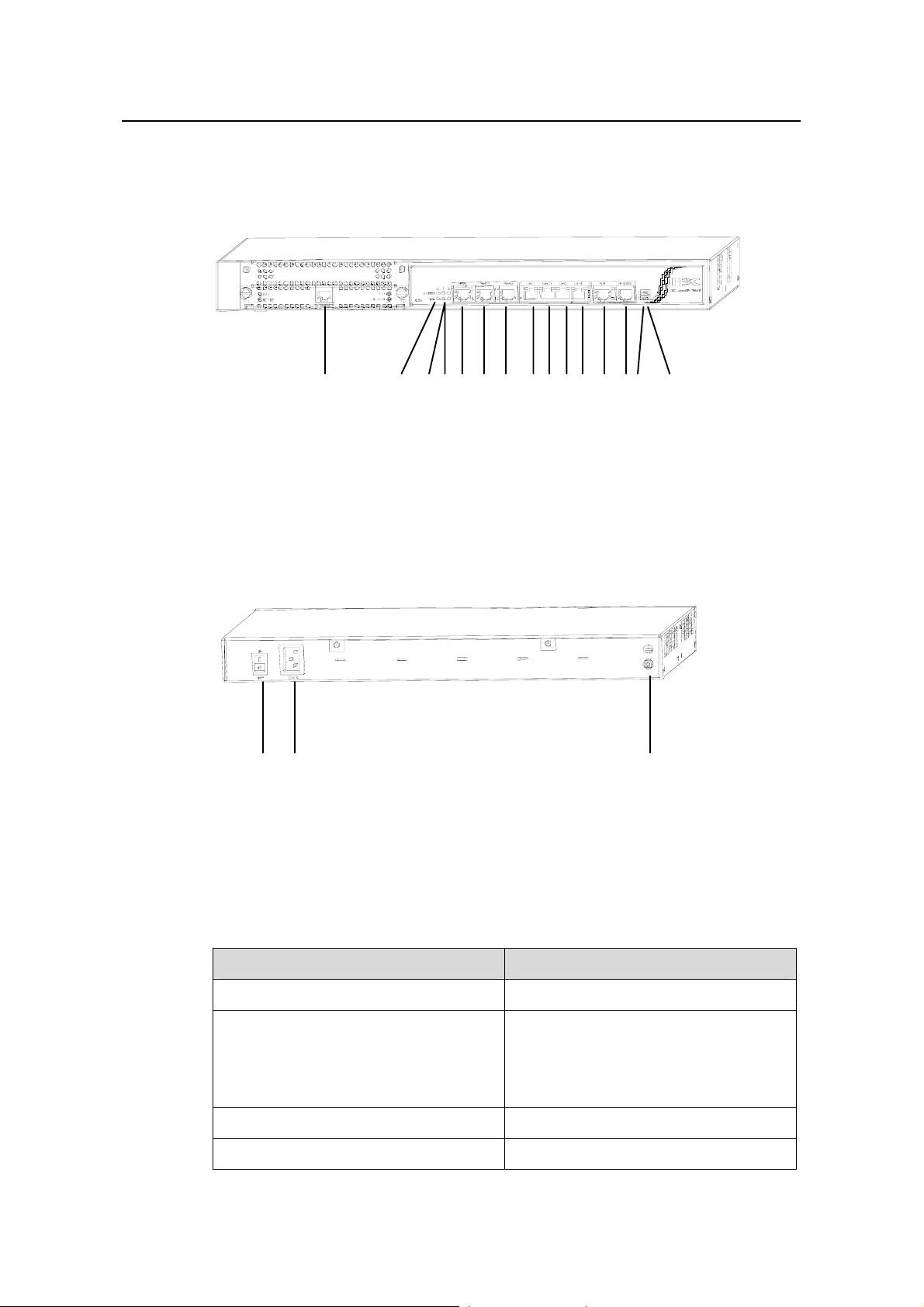
1.2.1 Appearance
Product Overview
(1)
(1) MIM slot (2) Two LEDs for the fixed WAN 0 interface
(3) Two LEDs for the fixed WAN 1 interface (4) Two LEDs for the fixed WAN 2 interface
(5) Fixed WAN 0 interface (WAN 0) (6) Fixed WAN 1 interface (WAN 1)
(7) Fixed WAN 2 interface (WAN 2) (8) Fixed LAN 0 interface (LAN 0)
(9) Fixed LAN 1 interface (LAN 1) (10) Fixed LAN 2 interface (LAN 2)
(11) Fixed LAN 3 interface (LAN 3) (12) Auxiliary port (AUX)
(13) Console port (CONSOLE) (14) System LED (SYS)
(15) Power LED (PWR)
Figure 1-1 Front panel of the H3C SecPath F100-A firewa
(1) (2) (3)
(1) Power switch (2) Power socket
(3) Grounding screw
(2) (3)(4)(5) (6) (7) (8)(9)(10)(11)(12)(13)(14) (15)
ll
Figure 1-2 Rear panel of the H3C SecPath F100-A firewa
1.2.2 System Specifications
Table 1-1 Technical specifications of the H3C SecPath F100-A firewall
Item Description
MIM slot 1
Fixed interface
Boot ROM 512 KB
DDR SDRAM 256 MB
1-3
ll
Four 10/100 Mbps LAN interfaces, three
10/100 Mbps WAN interfaces
One AUX port
One console port (CONSOLE)
Page 13

Installation Manual
H3C SecPath F100-A Firewall Chapter 1
Item Description
Product Overview
Flash memory 16 MB
Physical dimensions (H × W × D)
Weight
44 × 436 × 330 mm (1.7 × 17.2 × 13.0
in.) (excluding feet)
4 kg (8.8 lb)
Rated voltage: 100 VAC to 240 VAC, 50
Power supply
Hz or 60 Hz
Rated current: 1.5 A
Max. power consumption
Operating temperature
Operating humidity (noncondensing)
54 W
0°C to 40°C (32°F to 104°F)
10% to 90%
Note:
Double data rate synchronous dynamic random access memory (DDR SDRAM) stores
the communication data of the running system with the CPU.
1.2.3 LEDs
Table 1-2 LEDs on the H3C SecPath F100-A firewall
PWR
SYS
LINK/ACT
100M
LED Description
Power supply unit (PSU) LED: OFF
means the PSU is not supplying power
to the device. ON means the PSU is
supplying power to the device.
System operating status LED: Blinking
means the system is operating normally.
OFF means the system is operating
abnormally.
OFF means no link is present. ON
means a link is present. Blinking means
packets are being transmitted/received.
OFF means packets are being
transmitted/received at 10 Mbps on the
interface. ON means packets are being
transmitted/received at 100 Mbps on the
interface.
1-4
Page 14

Installation Manual
H3C SecPath F100-A Firewall Chapter 1
1.2.4 Fixed Interface Attributes
I. Console port (CONSOLE)
Table 1-3 Attributes of the console port
Item Description
Product Overview
Connector
Interface standard
Baud rate
RJ-45
RS-232
1,200 bps to 115,200 bps, defaults to
9,600 bps
Connected to an ASCII terminal
Connected to the serial interface of a
Service
local PC running terminal emulation
software
Command line interface (CLI)
II. AUX port
Table 1-4 Attributes of the AUX port
Item Description
Connector
Interface standard
RJ-45
RS-232
Baud rate 1,200 bps to 115,200 bps
Service
Modem dialup
Backup
III. Ethernet interfaces
The H3C SecPath F100-A firewall provides seven 10/100 Mbps autosensing Ethernet
interfaces. Their attributes are described in
Table 1-5.
Table 1-5 Attributes of the Ethernet interfaces
Item Description
Connector
RJ-45
1-5
Page 15

Installation Manual
H3C SecPath F100-A Firewall Chapter 1
Item Description
Product Overview
Interface type
Frame format
Operating mode
Both LAN and WAN interfaces support
auto-MDI/MDIX.
Ethernet_II
Ethernet_SNAP
10/100 Mbps autosensing
Half/full duplex
1-6
Page 16

Installation Manual
H3C SecPath F100-A Firewall Chapter 2
Chapter 2 Installation Preparations
2.1 General Site Requirements
The H3C SecPath F100-A firewall must be used indoors. To guarantee normal
operation and longevity of your device, its installation site should meet the
requirements described in this chapter.
2.1.1 Temperature and Humidity
The equipment room must maintain proper humidity to prevent poor insulation,
electricity creepage and corrosion accompanying high humidity, or washer contraction
and electrostatic discharge accompanying low humidity. In dry environments where the
relative humidity is very low, electrostatic discharge (ESD) is more likely to happen
causing the complementary metal-oxide-semiconductor (CMOS) circuitry to fail.
Installation Preparations
Table 2-1 lists the temperature and humidity requirements.
Table 2-1 Temperature/humidity requirements in the equipment room
0°C to 40°C (32°F to 104°F)
2.1.2 Cleanliness
Dust is hazardous to the operating safety of your device. Dust buildup on the chassis
may result in static absorption, causing poor contact of metal components or points.
When indoor humidity is extremely low, this is more likely to happen to shorten the
useful life of the device and cause communication failures.
The equipment room must be free of explosion hazards and the electrical and magnetic
conductible dust as well. The following table lists the limits on dust particles:
Table 2-2 Limits on the dust particles in the equipment room
Mechanical active
material
Dust particle
Temperature Relative humidity
Unit Content
Particle/m³
10% to 90% (noncondensing)
4
≤ 3 × 10
(No visible dust on desk in three days)
Note: Dust particles diameter = 5µm
2-1
Page 17

Installation Manual
H3C SecPath F100-A Firewall Chapter 2
Besides, the equipment room should meet the rigorous limits on salt, acid and sulfide to
eliminate corrosion and premature aging of some parts, as shown in the
Table 2-3 Harmful gas limits in the equipment room
Gas Max content (mg/m3)
Installation Preparations
Table 2-3.
SO
2
H2S 0.006
NH
3
Cl
2
2.1.3 ESD Prevention
By design, the H3C SecPath F100-A firewall is ESD preventative, but excessive
buildup of static electricity can still damage the card circuitry and even the entire device.
On the communication network connected to the firewall, static electricity is primarily
introduced from the outside electrical fields, such as the outdoor high-voltage power
cabling and lightning, and from the inside system, such as indoor environment, floor
material and the equipment frame. To avoid damage, ensure that:
z The device is well grounded.
z The equipment room is dust-proof.
z Maintain adequate temperature and humidity.
z Wear an ESD-preventive wrist strap and clothes when contacting the circuit board.
z Place the removed circuit board upward on the ESD-preventive workbench, or into
a static shielded bag.
z Hold the circuit board by its edge when observing or moving it, avoiding direct
contact with the elements on it.
0.2
0.05
0.01
2.1.4 Electromagnetic Compatibility
All interference sources, from the outside or from the inside of the device/application
system, adversely affect the device in the conduction patterns of capacitance coupling,
inductance coupling, electromagnetic wave radiation, and common impedance
(including grounding system) coupling. To prevent the interference, do the following:
z Take effective measures against interference from the power grid.
z Use a separate grounding system or lightning protection grounding from that for
the power supply equipment and keep them as far as possible.
z Keep the device far away from strong power wireless launchers, radar launchers
and high frequency and high-current equipment.
z Use electromagnetic shielding when necessary.
2-2
Page 18

Installation Manual
H3C SecPath F100-A Firewall Chapter 2
2.1.5 Lightning Protection
By design, the H3C SecPath F100-A firewall is lightning protective; but excessive
lightning may still damage the device. To protect the device better, you are
recommended to:
z Ensure the grounding screw of the chassis is securely connected to the earth
ground.
z Ensure the earth point of the power socket is securely connected to the earth
ground.
z Add a lightning arrester onto the front end of the power input to better protect the
power supply from lightning strikes.
2.1.6 Checking the Rack
When installing the H3C SecPath F100-A firewall, observe the following:
z Reserve adequate clearance at the air inlet and exhaust for adequate ventilation
inside the chassis.
z The rack has a good ventilation system.
z The rack is stable enough to support the weight of the device and the installation
accessories.
z The rack is well-grounded.
Installation Preparations
2.2 Safety Precautions
When reading this manual, pay adequate attention to the following.
Warning appears in operation procedures that, if performed incorrectly, might
cause bodily injury to the operators or damage the device.
Caution appears throughout this manual in procedures that, if performed
incorrectly, might affect the operation of the device.
When installing or using on the firewall, you are recommended to:
z Keep the firewall far away from the heat sources and water/liquid.
z Make sure that the firewall has been correctly grounded.
z Wear an ESD-preventive wrist strap in installation and maintenance, making sure
that the strap has good skin contact.
z Do not hot swap the console cable or AUX cable.
z Adopt uninterrupted power supply (UPS).
2-3
Page 19

Installation Manual
H3C SecPath F100-A Firewall Chapter 2
2.3 Unpacking Inspections
Check the arrived shipment contents against the packing list, making sure all the items
are included and in good condition. Contact your agent for shortage or wrong delivery.
2.4 Installation Tools, Meters and Equipment
I. Tools
z Phillips screwdriver
z ESD-preventive wrist strap
z Static shielding bag
II. Cables
z Grounding wire and power cord
z Console cable
z Optional cables
Installation Preparations
III. Meters and other equipment
z Hub or LAN switch
z Console terminal (or a PC)
z Multimeter
Note:
The firewall is not shipped with any installation tools, meters, or equipment. You must
prepare them yourself.
2-4
Page 20

Installation Manual
H3C SecPath F100-A Firewall Chapter 3
Chapter 3 Firewall Installation
3.1 Installation Flow
Start
Install cabinet (optional)
Install the device to
the specified location
Connect PGND wire
Connect power cord
Firewall Installation
Connect the device to
console terminal
Check
Power on
Normal?
Yes
Power off and disconnect
the power cord
Install MIM (optional)
Connect device to Ethernet
Check
Connect the power
cord/power on
End
Troubleshooting
No
Power off
Figure 3-1 Installation flow for the firewall
3-1
Page 21

Installation Manual
H3C SecPath F100-A Firewall Chapter 3
Caution:
Before you install the H3C SecPath F100-A firewall, make sure:
z You have read Chapter 2 carefully.
z The requirements listed in Chapter 2 are matched.
3.2 Mounting the Firewall
You can place the H3C SecPath F100-A firewall on a workbench/tabletop or mount it in
a 19-inch standard rack.
3.2.1 Free-Standing
Place the firewall on a clean and flat workbench/tabletop. To prevent any damage,
observe the following:
Firewall Installation
z Ensure the workbench/table is stable enough.
z Allow 10 cm (3.9 in.) of clearance around the ventilation openings.
z Do not place heavy stuff on the firewall.
3.2.2 Rack-Mounting
The H3C SecPath F100-A firewall is designed to be mounted in 19-inch standard racks.
Table 3-1 shows its physical dimensions.
Table 3-1 Physical dimensions of the H3C SecPath F100-A firewall
H3C SecPath F100-A firewall
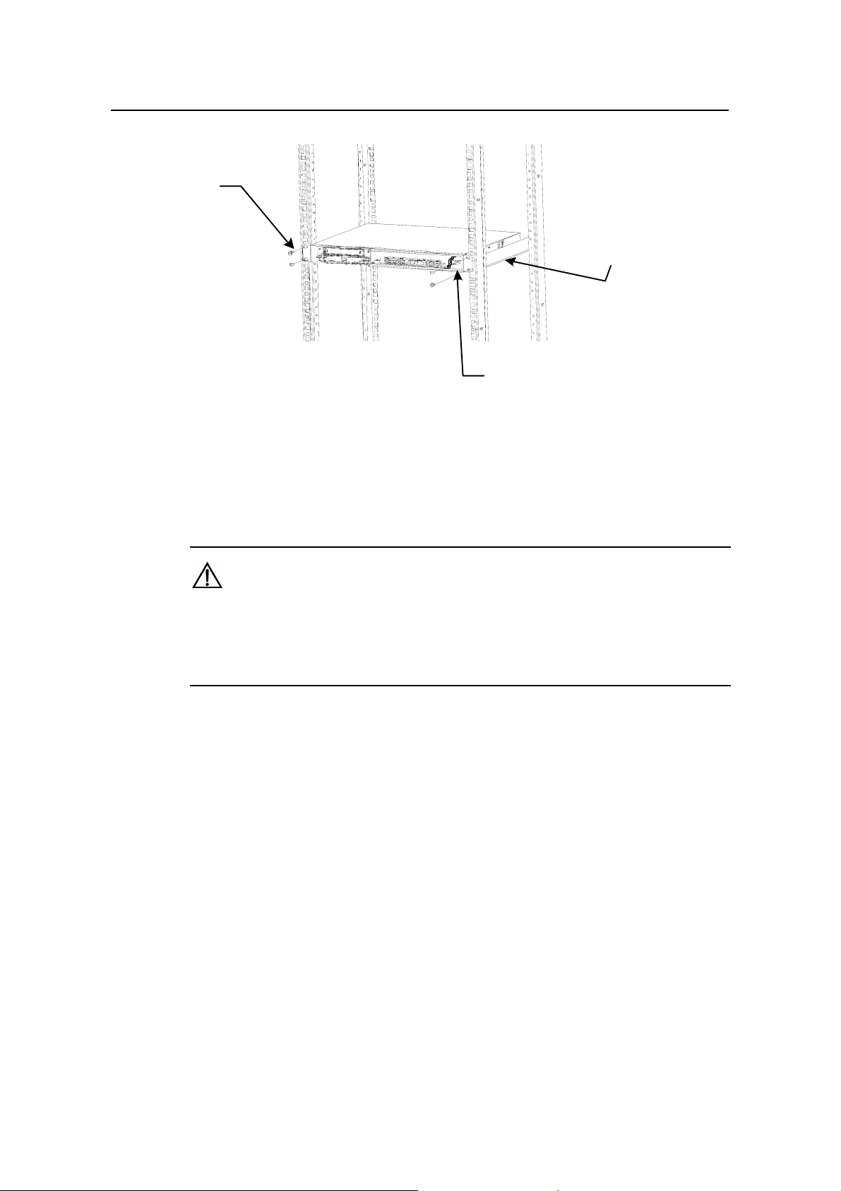
Follow these steps to rack-mount the H3C SecPath F100-A firewall:
Step 1: Check the grounding and stability of the rack. Use the screws to fix the
mounting ears at both sides near the front panel of the device.
Step 2: Put the device in a rack tray. Depending on the actual situation, slide the device
along the guide rails to an appropriate place.
Model
Physical dimensions (H × W × D)
44 × 436 × 330 mm (1.7 × 17.2 × 13.0
in.) (excluding feet)
Step 3: Fix the mounting ears to the rack posts with suitable antirust pan-head screws.
Make sure that the device is placed horizontally and securely fixed.
3-2
Page 22
Installation Manual
H3C SecPath F100-A Firewall Chapter 3
(1)
(3)
Firewall Installation
(1) Screws (four) (2) Mounting ear
(3) Guide rail
Figure 3-2 Rack-mount the firewa
ll
3.3 Connecting the PGND Wire
Caution:
Connection of the PGND wire is an important guard against the lightning and
interference. Therefore, the user must first correctly connect the PGND wire before
installing and using the firewall.
The H3C SecPath F100-A firewall provides a grounding screw, which must be well
grounded, so as to safely conduct the inductive and leaky current to the earth ground,
and thereby improve the capability of the whole device to guard against the
electromagnetic interference.
(2)
The grounding screw of H3C SecPath F100-A firewall, which is marked with grounding
symbol, is at the right end on the real panel, as shown in
Figure 1-2.
Use a PGND wire to connect the grounding screw to the earth ground, and the
grounding resistance should not be greater than 5-ohm. Likewise, if the firewall is
installed in a 19-inch standard rack, this rack is required to be grounded too.
3-3
Page 23

Installation Manual
H3C SecPath F100-A Firewall Chapter 3
Caution:
The firewall must be well grounded during its operation. Otherwise, it cannot be
protected reliably from lightning, which may damage the firewall itself and even the
peer device.
3.4 Connecting to the Console Terminal
I. Console port
The H3C SecPath F100-A firewall provides an RS-232 asynchronous serial console
port, through which you can configure the device. For the attributes of the console port,
refer to section
II. Console cable
1.2.4 I. "Console port (CONSOLE)”.
Firewall Installation
The console cable is an 8-core shielded cable. At one end of the cable is an RJ-45
connector that can be plugged to the console port of the firewall; at the other end is a
DB9 (female) connector, which can be plugged to the serial interface of the console
terminal.
Figure 3-3 illustrates a console cable.
A
X3
A
Figure 3-3 Console cable assembly
III. Connecting the console cable
Before configuring the firewall through a console terminal, follow these steps to connect
the console cable:
Step 1: Select a console terminal. The console terminal can be either a PC or a
standard ASCII terminal with an RS-232 serial interface.
Step 2: Connect the cable. Turn the power switch off, connect the DB9 serial interface
of the console cable to the PC, and then connect the RJ-45 interface to the console port
of the firewall.
Verify the connection and power up the firewall and console terminal. The console
terminal shows the startup information of the firewall if the connection is correct. For
details, see section
4.1.3 “Booting Process”.
3-4
Page 24

Installation Manual
H3C SecPath F100-A Firewall Chapter 3
3.5 Connecting to the Ethernet Interface
I. Ethernet interface
H3C SecPath F100-A firewall provides four fixed 10/100 Mbps autosensing LAN
interfaces, and three fixed 10/100 Mbps autosensing WAN interfaces for connection to
switches or routers.
Note:
The four LAN interfaces on H3C SecPath F100-A firewall can work at Layer 2 and in
Hub mode. You can configure the four LAN interfaces to work at Layer 3 by executing
the insulate command in system view. At this time, the interfaces LAN0, LAN1, LAN2
and LAN3 on the firewall correspond to E0/0, E0/1, E0/2 and E0/3 interfaces in the
command line respectively; by executing the undo insulate command in system view,
you can configure the four LAN interfaces to work in Hub mode. At this time, the
interfaces LAN0, LAN1, LAN2 and LAN3 on the firewall correspond to interface E0/0 in
the command line; WAN0, WAN1 and WAN2 interfaces correspond to E1/0, E1/1 and
E1/2 interfaces in the command line respectively.
Firewall Installation
II. Ethernet cable
The H3C SecPath F100-A firewall uses the category-5 twisted pair cable to connect its
Ethernet interfaces. See
Figure 3-4 Ethernet cable assembly
Note:
When preparing network cables, it is recommended to use shielded cables for the sake
of electromagnetic compatibility.
Figure 3-4.
3-5
Page 25

Installation Manual
H3C SecPath F100-A Firewall Chapter 3
III. Connecting the Ethernet cable
Take the LAN0 interface on the front panel of the H3C SecPath F100-A firewall for
example. Follow these steps to connect its Ethernet cable:
Caution:
Read the symbol above the interface carefully to avoid misconnection.
Step 1: Connect one end of the Ethernet cable to the firewall and the other end to the
peer device.
Step 2: Check that the LINK/ACT LED corresponding to LAN0 is on. ON means a link is
present on the interface. OFF means no link is present on the interface and you should
check the connection.
Firewall Installation
3.6 Connecting the Power Cord
The H3C SecPath F100-A firewall has AC-powered model.
I. AC power supply
AC input: 100 VAC to 240 VAC, 50 Hz or 60 Hz
Figure 1-2 shows the power socket on an AC-powered model.
II. Recommended AC power socket
You are recommended to use a single-phase three-terminal socket with an earth
contact, which must be properly grounded. The building ground system is often buried
during the wiring engineering. Make sure that the building ground system is normal
before connecting the AC power cord.
III. Connecting the AC power cord
Step 1: Make sure that the grounding screw on the chassis is securely connected to the
earth ground.
Step 2: Make sure that the power switch is in the OFF position. Connect one end of the
AC power cord to the AC-input socket (100 VAC to 240 VAC) on the left end of the rear
panel and the other end to the AC site power.
Step 3: Push the site power to ON position.
Step 4: Push the power switch of the firewall to ON position.
Step 5: Check that the PWR LED on the front panel is on. ON means the power
connection is correct.
3-6
Page 26

Installation Manual
H3C SecPath F100-A Firewall Chapter 3
Step 6: Check that the SYS LED on the front panel is blinking. Blinking means the
hardware system is operating normally.
3.7 Verifying Installation
Each time you power up the H3C SecPath F100-A firewall during installation, verify
that:
z Enough clearance has been reserved around the ventilation openings of the
device and the workbench/rack is stable enough.
z Proper power supply is used.
z The PGND wire is correctly connected.
z The firewall has been correctly connected to other devices, such as a console
terminal.
Note:
The installation verification is very important, because the stability, grounding of the
firewall and power supply will directly affect the operation of the firewall.
Firewall Installation
3-7
Page 27

Installation Manual
H3C SecPath F100-A Firewall Chapter 4
Chapter 4 Firewall Configuration
4.1 Booting
For the initial use of the H3C SecPath F100-A firewall, you can only make CLI
configuration through the console port.
4.1.1 Setting Up a Configuration Environment
I. Connecting a console terminal to the firewall
Connect the RJ-45 connector of the console cable to the console port on the firewall
and the DB9 connector to the serial interface on the PC (see
Figure 4-1).
Firewall Configuration
RS-232 serial interface
PC
Console cable
Figure 4-1 Local configuration through the console port
H3C SecPath F100-A
Console port
II. Setting terminal parameters
Step 1: Start the PC (or the console terminal), run on the PC the emulation (the Terminal
on Windows3.1, or the HyperTerminal on Windows95/Windows98/Windows NT for
example) and create a new connection. Enter the name of the new connection in the
[Name] field and click <OK>. See
Figure 4-2.
4-1
Page 28

Installation Manual
H3C SecPath F100-A Firewall Chapter 4
Figure 4-2 Create a new connection
Step 2: Define terminal parameters (using the HyperTerminal on Windows98 as an
example).
Firewall Configuration
1) Select connection port
Select the serial interface to be used from the Connect Using drop-down list. The serial
interface selected here must be the one connected to the console cable.
Figure 4-3 Select connection port
2) Set the connection port
The [Settings] tab appears as shown in
parameters as follows:
z Bits per second = 9600
4-2
Figure 4-4, and set the serial interface
Page 29

Installation Manual
H3C SecPath F100-A Firewall Chapter 4
z Data bits = 8
z Parity = None
z Stop bit = 1
z Flow control = None
Click <OK> and the HyperTerminal dialog box appears.
Firewall Configuration
Figure 4-4 Define port parameters
3) Select emulation type
Choose [Properties/Settings] to enter the corresponding page and select the emulation
as VT100 or Auto detect. Click <OK> and HyperTerminal window appears.
4-3
Page 30

Installation Manual
H3C SecPath F100-A Firewall Chapter 4
Firewall Configuration
Figure 4-5 Select emulation type
4.1.2 Powering Up the Firewall
I. Checking before power-up
Check the following issues before powering up the firewall:
z Both the power cord and the PGND wire are correctly connected.
z The voltage of the power supply matches the requirements.
z The console cable is correctly connected. The console terminal (or PC) has been
started and the associated parameters have been set on it.
Caution:
Locate the power switch of the power supply in the equipment room before powering up
the firewall. Then, if an accident occurs, you can quickly shut off the power.
II. Powering up the Firewall
z Turn on the site power.
z Turn on the power switch of the firewall.
4-4
Page 31

Installation Manual
H3C SecPath F100-A Firewall Chapter 4
III. Checking after power-up
After the firewall is powered up, please check:
z The LEDs on the front panel are normal.
Firewall Configuration
Refer to section
z The console terminal display is correct.
After powering up the firewall, you can see the startup window on the console terminal
(see section
4.1.3 “Booting Process”). After the startup (or power-on self-test), you are
prompted to press <Enter>. When the prompt <H3C> appears, the system is ready for
your configuration.
4.1.3 Booting Process
After being powered up, the firewall first runs the Boot ROM program. The terminal
screen displays the following system information.
Note:
The contents displayed on the terminal may vary with Boot ROM versions.
**************************************************
* *
* H3C SecPath Series Gateway Boot ROM V1.17 *
* *
**************************************************
Copyright(C) 2004-2007 by Hangzhou H3C Technologies Co.,Ltd.
Compiled at Wed Apr 12 17:39:36 CST 2006
Testing memory...OK!
256M bytes DDR SDRAM Memory
16M bytes Flash Memory
Hardware Version is 3.0
CPLD Version is 1.0
Press Ctrl-B to enter Boot Menu
1.2.3 “LEDs” for the LED description.
Press <Ctrl+B> right now and the system will enter the Boot menu. Otherwise, the
system will start the program decompression process.
4-5
Page 32

Installation Manual
H3C SecPath F100-A Firewall Chapter 4
Note:
To enter the Boot menu, you need to press <Ctrl+B> within three seconds after the
prompt information “Press Ctrl-B to Enter Boot menu...” appears.
The terminal screen gives this information when the system starts decompression and
initialization:
System is self-decompressing.............................................
System is starting...
User interface Con 0 is available.
Press ENTER to get started.
Press <Enter>, and the system displays (if login authentication is not enabled):
Firewall Configuration
<H3C>
Now the firewall has entered user view and is ready for your configuration.
4.2 Configuration Fundamentals
4.2.1 Basic Configuration Procedures
Following are the basic steps that you can follow to configure the firewall.
Step 1: Figure out detailed networking requirements, including networking objectives,
the role of the firewall in the network, transmission medium, security policy, and
network reliability.
Step 2: Draw a networking topology based on the requirements.
Step 3: Configure IP addresses for the interfaces on the firewall.
Step 4: Configure routes, and if a dynamic routing protocol is enabled, set parameters
for the protocol.
Step 5: Configure security features as required.
Step 6: Configure reliability features as required.
For more information on the configuration of protocols and functions for the firewall, see
the Operation Manual and Command Manual of the corresponding product.
4-6
Page 33

Installation Manual
H3C SecPath F100-A Firewall Chapter 4
4.2.2 Command Line Interface
I. Characteristics of CLI
The command line interface (CLI) offers a series of configuration commands. It allows
you to:
z Configure the device locally through the console port.
z Telnet to configure the device locally or remotely, and then telnet to access and
manage other devices.
z Get on-line help whenever you enter <?>.
z Test network connectivity quickly with network diagnostic tools, such as tracert
and ping.
z Have detailed debugging information for troubleshooting your network.
z Enter the conflict-free keyword portion instead of the whole command, because
the CLI supports command prompting. For example, you simply need to enter
“dis” for the display command.
II. CLI
Firewall Configuration
In system view, all the commands are put into groups for the convenience of
management, each being associated to a view. You can switch between the views by
executing some particular commands. Under normal circumstances, you can only
execute the commands appropriate to the view that you access. However, you are
allowed to execute some common commands (such as ping, display,
current-configuration, and interface) in any view.
4-7
Page 34

Installation Manual
H3C SecPath F100-A Firewall Chapter 5
Chapter 5 Software Maintenance
The firewall manages three types of files:
z Boot ROM program files
z Application program files
z Configuration files
Software maintenance mainly involves upgrading/downloading Boot ROM/application
program files and uploading/downloading configuration files.
5.1 Boot Menu
This section introduces the Boot menu that you use in maintaining the software of the
firewall.
Software Maintenance
Set up a configuration environment (see
Figure 4-1) and then boot the firewall. Press
<Ctrl+B> when the system prompts “Press Ctrl-B to enter Boot menu”. Then the system
displays:
Please input Boot ROM password :
Caution:
z Press <Ctrl+B> within three seconds to access the Boot menu after the prompt
“Press Ctrl-B to Enter Boot menu...” appears. Otherwise, the system starts
decompressing the program.
z If you want to access the Boot menu after the system starts decompressing the
program, you need to reboot the firewall.
Type the correct password and press <Enter> (If no Boot ROM password has been set,
just press <Enter>). The system accesses the Boot menu shown as follows:
I. Boot menu on the H3C SecPath F100-A firewall
Boot Menu:
1: Download application program with XMODEM
2: Download application program with NET
3: Display file in flash
4: Delete file from flash
5: Start up and ignore configuration
6: Enter debugging environment
5-1
Page 35

Installation Manual
H3C SecPath F100-A Firewall Chapter 5
7: Boot Rom Operation Menu
8: Do not check the version of the software
9: Exit and reboot
Enter your choice(1-9):
Further description is given for the option 8:
If you fail to upgrade the software and the system prompts “invalid version” although
you use the correct software version, you can select this option to ignore the version
check during software upgrade. Note that this option works only once when you select
it. The system resumes version check after you reboot the firewall.
II. Boot ROM operation menu of the H3C SecPath F100-A 100F
As mentioned previously, you can select 7 in the Boot menu to enter the Boot ROM
operation menu as follows:
Boot ROM Operation Menu:
1: Download Boot ROM with XModem
2: Download Extended Segment of Boot ROM with XModem
3: Restore Extended Segment of Boot ROM from FLASH
4: Backup Extended Segment of Boot ROM to FLASH
5: Exit to Main Menu
Enter your choice(1-5):
Software Maintenance
The menu provides approaches to upgrade, back up, and restore the Boot ROM
program. See the sections
5.3 “Backing Up and Restoring the Extended Segment of the Boot ROM” for
and
5.2 “Upgrading Application and Boot ROM Using XModem”
details.
Caution:
You are recommended to upgrade the software under the guidance of technical support
engineers. When upgrading the firewall, make sure that the version of the Boot ROM
software is consistent with the application program.
5.2 Upgrading Application and Boot ROM Using XModem
You can use XModem to upgrade the software through the console port even without
setting up a configuration environment.
I. Upgrading the application program
Step 1: Enter the Boot menu and select 1 to download an application program using
XModem. These download speeds are available on the firewall:
5-2
Page 36

Installation Manual
H3C SecPath F100-A Firewall Chapter 5
Downloading application program from serial ...
Please choose your download speed:
1: 9600 bps
2: 19200 bps
3: 38400 bps
4: 57600 bps
5: 115200 bps
6: Exit to Main Menu
Enter your choice(1-6):
Step 2: Select an appropriate downloading speed (for example, 115200 bps by entering
5).
Download speed is 115200 bps. Change the terminal's speed to 115200 bps, and
select XModem protocol. Press ENTER key when ready.
Step 3: Change your terminals baud rate (see Figure 4-4) to the same baud rate for
software downloading (115200 bps in this example). After that, disconnect the terminal
([Dial-in/Disconnect]), reconnect it ([Dial-in/Dialing]), and press <Enter> to start
downloading. Then the system displays:
Software Maintenance
Downloading ... CCCCC
Note:
The new baud rate takes effect only after you disconnect and reconnect the terminal
emulation program.
Step 4: Select [Transmit/Send File] in the HyperTerminal window. The following dialog
box pops up:
Figure 5-1 Send File dialog box
Step 5: Click <Browse>, select the application file to be downloaded, set protocol to
XModem, and click <Send>.The following interface pops up:
5-3
Page 37

Installation Manual
H3C SecPath F100-A Firewall Chapter 5
Figure 5-2 Sending File interface
Software Maintenance
Step 6: After completing the downloading, the system begins writing data to the Flash
memory and then displays the following information in the terminal window, indicating
the completion of the downloading:
XModem download completed, Packet length 8790321 bytes.
System file length 7868992 bytes, http.zip file length 921329 bytes.
Writing file flash:/system to FLASH...
Please wait, it may take a long time
################################################
Writing into Flash Succeeds.
Writing file flash:/http.zip to FLASH...
Please wait, it may take a long time
##########################################################################
######
#########
Writing into Flash Succeeds.
Please use 9600 bps.Press <ENTER> key to reboot the system.
Restore the speed of the console terminal to 9600 bps as prompted, and then
disconnect and reconnect the terminal. The system boots normally.
II. Upgrading the entire Boot ROM program
Step 1: Enter the Boot menu, and select 7 to enter the Boot ROM operation menu.
5-4
Page 38

Installation Manual
H3C SecPath F100-A Firewall Chapter 5
Step 2: Select 1 in the Boot ROM operation menu to download the Boot ROM program
using XModem. The subsequent operation steps are the same as those upgrading the
application program.
Caution:
If you fail to upgrade the entire Boot ROM program, you cannot restore it on site.
Therefore, you can only upgrade the entire Boot ROM program under the direction of
technical support engineers and when it is urgently necessary.
III. Upgrading the extended segment of the Boot ROM program
Step 1: Enter the Boot menu, and select 7 to enter the Boot ROM operation menu.
Step 2: Select 2 in the Boot ROM operation menu to download the extended segment
of Boot ROM with XModem. The subsequent operation steps are the same as those for
upgrading the application program.
Software Maintenance
Caution:
This upgrade approach is used to upgrade only a portion of the Boot ROM program, so
you may make a second attempt once an error occurs.
5.3 Backing Up and Restoring the Extended Segment of the Boot ROM
I. Backing up the extended segment to Flash memory
Follow these steps to back up the Boot ROM program.
Step 1: Enter the Boot menu, and select 7 to enter the Boot ROM operation menu.
Step 2: Select 4 in the Boot ROM operation menu to copy the current extended
segment of the Boot ROM program to the Flash memory.
Backup Extended Segment, are you sure?[Y/N]
Enter Y and the system starts backing up the extended segment.
If the backup attempt is successful, the following message appears:
Writing to FLASH.Please wait...####
Backuping Boot ROM program to FLASH successed!
5-5
Page 39

Installation Manual
H3C SecPath F100-A Firewall Chapter 5
Step 3: When the Boot ROM operation menu appears again, select 5 to exit and reboot
the firewall.
II. Restoring the extended segment from the Flash memory
If faults occur to the extended segment of the Boot ROM program or you upgrade it by
mistake, you can restore the extended segment saved in the Flash memory to the Boot
ROM following these steps:
Step 1: Enter the Boot menu, and select 7 to enter the Boot ROM operation menu.
Step 2: Select 3 in the Boot ROM operation menu to restore the extended segment of
the Boot ROM program from the Flash memory. The system displays the following
message:
Restore Extended Segment, are you sure?[Y/N]
Enter Y and the system starts backing up the extended segment.
If the restoration is successful, the system displays:
Writing to Boot ROM.Please wait...######
Restoring Boot ROM program successed!
Software Maintenance
Step 3: When the Boot ROM operation menu appears again, select 5 to exit and reboot
the firewall.
5.4 Upgrading the Application Program Using TFTP
The application program is downloaded using TFTP through the Ethernet interface. In
this case, the firewall acts as the client and must be connected to the TFTP server
through one of its fixed Ethernet interfaces.
Caution:
The TFTP server program is not shipped with the H3C SecPath F100-A firewall. You
need to purchase and install it by yourself.
The H3C SecPath F100-A firewall can only act as the TFTP client, so you can only
upgrade the application program using TFTP in these steps:
1) Start the TFTP server.
Start the TFTP server on the PC connected to the Ethernet interface on the firewall and
set the path to the file to be downloaded.
2) Configure the firewall
Step 1: Boot the firewall and enter the Boot menu (refer to
5.1 “Boot Menu” for details).
Select 2 to enter the Net Port Download Menu shown as follows:
5-6
Page 40

Installation Manual
H3C SecPath F100-A Firewall Chapter 5
Net Port Download Menu:
1: Change Net Parameter
2: Download From Net
3: Exit to Main Menu
Enter your choice(1-3): 1
Step 2: Select 1 in the Net Port Download Menu to set parameters for the Ethernet
interface on the security gateway (including the interface in use, IP address and subnet
mask of the interface) and parameters for the TFTP server (including IP address of the
Ethernet interface on the TFTP server and the name of the application program).
Change Download parameter
Download device : WAN2
Download file(Max 60 char) :system
IP address of WAN2 :192.168.1.15
Subnet mask for WAN2 :255.255.255.0
IP address of the server :192.168.1.10
IP address of the gateway :10.110.95.117
Software Maintenance
Caution:
z The upgrade should be performed through interface WAN2 on the firewall.
z The IP address of the server: [192.168.1.10] field must be set to the IP address of
the TFTP server connected to the Ethernet interface on the firewall.
z You are recommended to configure the IP addresses of the network interface on the
TFTP server and that of the WAN2 on the firewall into the same network segment.
Step 3: After you input the last parameter value, the system displays the following
message and returns to the Net Port Download Menu:
Saving config, please wait...OK!
Net Port Download Menu:
1: Change Net Parameter
2: Download From Net
3: Exit to Main Menu
Enter your choice(1-3): 2
3) Download application program using TFTP
Select 2 to download the application program through TFTP. The system displays the
following message:
Starting the TFTP download...
..........................................................................
.......................
5-7
Page 41

Installation Manual
H3C SecPath F100-A Firewall Chapter 5
TFTP download completed, Packet length 8790321 bytes.
System file length 7868992 bytes, http.zip file length 921329 bytes.
Writing file flash:/system to FLASH...
Please wait, it may take a long time
####################################################################
Writing into Flash Succeeds.
Writing file flash:/http.zip to FLASH...
Please wait, it may take a long time
##########################################################################
######
#########
Writing into Flash Succeeds.
Software Maintenance
The downloading is successful. Press <Enter> to reboot the system.
5.5 Uploading/Downloading Applications/Files Using FTP
The H3C SecPath F100-A firewall offers FTP server function, which provides you
another way of updating configuration files, and upgrading application and Boot ROM
program. You only need to connect a FTP client, local or remote, to the firewall. When
you pass the authentication, you can upload and download configuration files or
applications.
Note:
Upload: Transfer files from PCs running FTP client to firewall, namely the put operation.
Download: Transfer files from firewall to PCs running FTP client, namely the get
operation.
I. Setting up upload/download environment
z Setting up the local upload/download environment
10.110.10.13/24
H3C SecPath F100-A (FTP Server)
PC
(FTP Client)
LAN
Ethernet interface
Figure 5-3 Set up the local upload/download environment
5-8
10.110.10.10/24
Page 42

Installation Manual
H3C SecPath F100-A Firewall Chapter 5
Step 1: Connect the PC to the Ethernet port of firewall.
Step 2: Configure the IP address of the Ethernet port of firewall. Here suppose it is
10.110.10.10.
Step 3: Configure the IP address of the PC. Here suppose it is 10.110.10.13.
Step 4: Copy the application, Boot ROM program or configuration files to a specific path.
Here suppose the path is C:\\ version.
Caution:
The network port IP address of the PC must be in the same network segment with that
of the Ethernet port of the firewall.
z Setting up the remote upload/download environment
Software Maintenance
H3C SecPath F100-A (FTP Server)
H3C SecPath F100-A (FTP Server)
10.110.20.13/24
10.110.20.13/24
10.110.20.13/24
PC
PC
PC
(FTP Client)
(FTP Client)
(FTP Client)
Router
Router
Router
H3C SecPath F100-A (FTP Server)
Ethernet interface
Ethernet interface
WAN
WAN
WAN
Ethernet interface
10.110.10.10/24
10.110.10.10/24
10.110.10.10/24
Figure 5-4 Set up the remote upload/download environment
Step 1: Connect the PC through WAN to any interface of the firewall. The IP addresses
of the PC and the firewall can be in different network segments.
Step 2: Copy the application, Boot ROM program or configuration files to a specific path.
Here suppose the path is C:\\ version.
II. Booting FTP server
Ask the technical personnel at the firewall side to make the following configuration:
Step 1: Configure authentication mode.
Note:
You can perform AAA authentication configuration as needed. See the AAA and
RADIUS configuration part in the Operation Manual and Command Manual of the
corresponding product for details.
5-9
Page 43

Installation Manual
H3C SecPath F100-A Firewall Chapter 5
Step 2: Add the username and password.
[VPNGateway] local-user VPNGateway
VPNGateway is the username.
Step 3: Add the password.
[VPNGateway-luser-vpngateway] password simple 123
Step 4: Add the service type and specify the FTP directory.
[VPNGateway-luser-vpngateway] service-type ftp ftp-directory flash:
Step 5: Add an authority level.
[VPNGateway-luser-vpngateway] level 3
Step 6: Enable the FTP server.
[VPNGateway] ftp-server enable
After the above operation, the FTP server is enabled on the firewall, and a user is set.
Then, any FTP client program can access FTP server using this user name and
password.
Software Maintenance
III. Uploading/downloading application, configuration files and uploading Boot
ROM program
Step 1: Enter the path of the files or applications in DOS window, perform FTP
command, and create the FTP connection to the firewall, for example:
C:\version\ftp 10.110.10.10
If the connection is set up, the system displays the following message (taking
Windows98 as an example):
Connected to 10.110.10.10
220 FTP server ready on SecPath Gateway at
User(10.110.10.10:(none)):
Step 2: Access FTP server using the configured user name and password.
User(10.110.10.10:(none)): SecPath Gateway
331 Password required for ftp
Password:
230 User ftp logged in
ftp>
At the prompt of ftp>, you can upload or download files.
Step 3: Upload/download applications, configuration files, or upload Boot ROM
programs.
5-10
Page 44

Installation Manual
H3C SecPath F100-A Firewall Chapter 5
Note:
By default, the application name of the firewall side is system, the filename is config.cfg,
Boot ROM filename extension is bootrom, and the entire Boot ROM filename is
bootromfull.
z Upload application, Boot ROM program, or configuration files.
ftp> put
local file
remote file
After the upload, at the prompt of “ftp>”, you can input dir to view the filenames and file
sizes on the firewall. If the upload succeeds, the size of the configuration file is the
same as that of the file on the host.
Software Maintenance
Caution:
z When using FTP to upgrade the application program, make sure that the firewall
has enough flash memory. If the memory is not enough, you need to use the delete
/unreserved command to permanently delete old version files or other files to save
the memory space; otherwise, new files cannot be uploaded.
z After uploading Boot ROM program using the put command, read the
bootrom/bootromfull program from Flash root directory using the upgrade bootrom
[ full ] command, and write it into Boot ROM to complete Boot ROM upgrade.
z After uploading the application program into the flash memory, you need to rename
the program file to “system” to make the program take effect at next startup.
z After uploading configuration files into the flash memory, you need to rename the file
to “config.cfg” to make the files take effect at next startup of the system, or use the
startup saved-configuration command to set the configuration files used for next
startup.
z Download application or configuration files
ftp> get
remote file
local file
Step 4: After the upload/download, quit the FTP client program.
ftp>quit
5-11
Page 45

Installation Manual
H3C SecPath F100-A Firewall Chapter 5
IV. Detaching the Web file
When the downloading using FTP is completed, the Web file is included in the
application program. You need to detach it from the application program using the
detach command.
<VPN Gateway> detach system
System file length 7856557 bytes, http file length 834724 bytes.
<VPN Gateway> dir
Directory of flash:/
0 -rw- 8691281 Jun 16 2009 06:46:36 system
1 -rw- 1830 Jun 17 2009 07:47:16 config.cfg
2 -rw- 834724 Jun 18 2009 02:22:39 http.zip
If the Web file is not included, the system gives the corresponding prompt. The Web file
name defaults to http.zip.
5.6 Modifying Boot ROM Password
Software Maintenance
You can use the Boot menu of the firewall to change the Boot ROM password.
Start the firewall. When “System starts booting” appears on the configuration terminal,
press <Ctrl+D>, and then the system prompts:
Please input Boot ROM password :
Caution:
z To enter the Boot menu, you must press <Ctrl+D> within three seconds after the
“System starts booting” prompt appears on the configuration terminal; otherwise,
the system starts decompressing the program.
z You need to restart the firewall if you want to enter the Loader menu after entering
the Boot ROM extended segment.
After entering the correct password, press <Enter>to enter the Boot menu (press
<Enter> directly if the password is not set), and the system displays the information as
follows:
Boot Menu:
1: Download Boot ROM with XModem
2: Download Extended Segment of Boot ROM with XModem
3: Modify Boot ROM password
4: System booting from Flash
5: Do not check the version of Extended Segment of Boot ROM
5-12
Page 46

Installation Manual
H3C SecPath F100-A Firewall Chapter 5
6: Exit and reboot
Enter your choice(1-6):
Following is the description on the options of Boot menu:
z 1: Download Boot ROM with XModem
z 2: Upgrade the extended segment of Boot ROM with XModem
z 3: Modify Boot ROM password
z 4: Boot the system from flash (This option requires backing up the extended
segment of Boot ROM in flash, refer to
z 5: Do not check the software version of extended segment of Boot ROM (This
5.3 for details.)
option is used for backward compatibility of version upgrade. When the software
version is correctly adopted for software upgrade, but you still cannot operate
successfully, the system prompts “invalid version”. At this time, select this option to
cancel the version checking for version upgrade. However, this option can function
only once, the version checking is restored after restarting the firewall.)
z 6: Exit from the Loader menu and restart the firewall.
Select 3 in the Boot menu to change the Boot ROM password, and the system prompts:
Software Maintenance
Modify Boot ROM password, are you sure?[Y/N]y
Please input new password(Max 32 char) :
Retype the new password(Max 32 char) :
Saving the password... Success!
Note:
The password can contain up to 32 characters.
5.7 Resetting a Lost Password
Please contact support technicians if your Boot ROM password or user password of the
firewall is lost. Then you can get assistance to enter the firewall again and set a new
password.
5-13
Page 47

Installation Manual
H3C SecPath F100-A Firewall Chapter 6
Chapter 6 Troubleshooting
6.1 Troubleshooting PSU
1) Symptom
The power LED (PWR) is always off.
2) Solution
Check whether:
z The power switch of the firewall is turned on.
z The site power supply is turned on.
z The power cord is properly connected.
z The required power supply is used.
Troubleshooting
Caution:
Do not hot-swap the power cable. If the PWR is still off after you have checked the
above items, contact the agent.
6.2 Troubleshooting Configuration System
If the firewall operates normally after being powered up, the console terminal displays
booting information; if the system fails, the console terminal displays nothing or just
illegible characters.
I. Troubleshooting no terminal display
1) Symptom
The console terminal displays nothing on the screen after the firewall is powered on.
2) Solution
Step 1: Check whether:
z The PSU operates normally.
z The console cable is connected correctly.
Step 2: If no problem is found, examine the parameters configured at the terminal (such
as HyperTerminal), or check the console cable.
6-1
Page 48

Installation Manual
H3C SecPath F100-A Firewall Chapter 6
II. Troubleshooting illegible characters
1) Symptom
The console terminal displays illegible characters on the screen after the firewall is
powered on.
2) Solution
Confirm the parameters are configured at the terminal (such as HyperTerminal):
z Bits per second = 9600
z Data bits = 8
z Parity = none
z Stop bits = 1
z Flow control = none
z Emulation = VT100
Reset them if they are not set to these values.
6.3 Troubleshooting Application Upgrading
Troubleshooting
I. Fault 1
1) Symptom
Boot the firewall, upgrade Comware software using TFTP, and the system displays the
following:
Net Port Download Menu:
1: Change Net Parameter
2: Download From Net
3: Exit to Main Menu
Enter your choice(1-3): 2
Starting the TFTP download...
Failed to connect the tftp server!!
Please check the network setting!!
2) Solution
The above symptom may be caused by either of the two problems:
z The TFTP server program does not run.
z The Ethernet is not connected properly.
Run the TFTP server program on the system, confirm that the IP address is set
correctly and the network cables are connected.
6-2
Page 49

Installation Manual
H3C SecPath F100-A Firewall Chapter 6
II. Fault 2
1) Symptom
Boot the firewall, upgrade Comware software using TFTP, and the system displays the
following:
Net Port Download Menu:
1: Change Net Parameter
2: Download From Net
3: Exit to Main Menu
Enter your choice(1-3): 2
Starting the TFTP download...
Failed to find the updated file
Please check the network setting!!
2) Solution
Troubleshooting
The above symptom is caused by either of the two problems:
z The downloaded files are not available.
z The paths of the files are not correct.
Confirm that the files to be downloaded are under the path specified by the TFTP
server.
III. Fault 3
1) Symptom
Boot the firewall, upgrade Comware software using TFTP, and the system displays the
following:
Net Port Download Menu:
1: Change Net Parameter
2: Download From Net
3: Exit to Main Menu
Enter your choice(1-3): 2
Starting the TFTP download...
The downloaded software is not a valid version.
Please download the correct version.
2) Solution
The above problem is caused by the wrong version of the download program, so the
program cannot pass the version authentication. Confirm that the program version is
correct.
6-3
Page 50

Installation Manual
H3C SecPath F100-A Firewall Chapter 6
Note:
There is a bar code pasted on the firewall. Since the bar code contains product and
maintenance information, you need to tell the agent about the information if you need to
fix the device.
Troubleshooting
6-4
Page 51

Installation Manual
H3C SecPath F100-A Firewall Chapter 7
Chapter 7 MIM Modules
7.1 MIM Options
Currently the H3C SecPath F100-A firewall supports these types of multifunctional
interface modules (MIMs):
z 1-port 10Base-T/100Base-TX FE interface module (1FE)
z 2-port 10Base-T/100Base-TX FE interface module (2FE)
z 4-port 10Base-T/100Base-TX FE interface module (4FE)
z High-performance network data encryption module (HNDE)
7.2 Installing and Removing an MIM
MIM Modules
Caution:
There is a shield finger on the front panel of the MIM module, which provides
electromagnetic shielding for the firewall. You must keep the shield finger intact when
replacing the module. Do not remove the shield finger.
Before installing MIMs, read
Chapter 2 “Installation Preparations” carefully.
I. Tools
ESD-preventive wrist strap
II. Installing an MIM
Caution:
Before performing any of the following operations, make sure you have completely
powered down the firewall to avoid getting electric shocks.
Step 1: Place the firewall with its front panel facing you.
Step 2: Turn off the site power and remove the power cord.
7-1
Page 52

Installation Manual
H3C SecPath F100-A Firewall Chapter 7
Step 3: Select a slot and push the MIM into the chassis until it is fully seated in the slot
and its front panel is flush with the front of the chassis.
Step 4: Tighten the captive screws to secure the MIM.
Step 5: Power up the firewall and check the state of the ACT LED for the slot on the
firewall. Blinking means the MIM is installed correctly.
Figure 7-1 Install the MIM I
MIM Modules
Figure 7-2 Install the MIM II
III. Removing an MIM
Step 1: Place the firewall with its front panel facing you.
Step 2: Turn off the site power and remove the power cord.
Step 3: Remove all interface cables from the front of the chassis.
Step 4: Loosen the captive screws at both sides of the MIM.
Step 5: Pull the MIM towards you until it is completely separated from the bottom of the
chassis.
Caution:
z If you remove an MIM and do not install a new one right away, you must replace the
blanking filler panel to prevent dust from entering the firewall and to provide
adequate ventilation.
z Do not operate at MIMs near the passageway to avoid accidents to the unit or the
removed MIMs.
7-2
Page 53

Installation Manual
H3C SecPath F100-A Firewall Chapter 7
7.3 Troubleshooting an MIM
You can read the LEDs on the MIM panel to check for the MIM installation.
If the MIM on the firewall does not operate normally, check that:
z Correct interface cables are used.
z The interfaces are working well by reading the interface LEDs.
z The configurations on the MIM are validated by executing the display command.
7.4 1FE/2FE/4FE Module
7.4.1 Introduction
1-/2-/4-port 10Base-T/100Base-TX Fast Ethernet interface module (1FE/2FE/4FE)
provides the communications between the firewall and a LAN.
The 1FE provides one 10/100 Mbps Ethernet interface with the RJ-45 connector, while
the 2FE and 4FE can provide two and four. All of them support:
MIM Modules
z The transmission distance of 100 meters (328 ft) over the category-5 twisted-pair
cable.
z The Operating rates of 100 Mbps and 10 Mbps, with autosensing.
z Full duplex (commonly used) and half duplex.
7.4.2 Appearance
I. Appearance of the 1FE module
Figure 7-3 shows the 1FE module.
Figure 7-3 1FE module
II. Appearance of the 2FE module
Figure 7-4 shows the 2FE module.
7-3
Page 54

Installation Manual
H3C SecPath F100-A Firewall Chapter 7
Figure 7-4 2FE module
III. Appearance of the 4FE module
Figure 7-5 shows the 4FE module.
MIM Modules
Figure 7-5 4FE module
7.4.3 Interface Attributes
Table 7-1 shows the interface attributes of the 1FE, 2FE and 4FE modules.
Table 7-1 Interface attributes of the 1FE, 2FE and 4FE modules
Attribute 1FE module 2FE module 4FE module
Connector RJ-45
Number of
connectors
Cable type Straight-through Ethernet cable
Operating mode
Frame format
1 2 4
Full/half duplex
10/100 Mbps autosensing
Ethernet_II
Ethernet_SNAP
7-4
Page 55

Installation Manual
H3C SecPath F100-A Firewall Chapter 7
7.4.4 Panel and Interface LEDs
Figure 7-6 shows the 1FE module panel.
MIM Modules
10/100BASE-TX
Figure 7-6 1FE module panel
Figure 7-7 shows the 2FE module panel.
01
Figure 7-7 2FE module panel
Figure 7-8 shows the 2FE module panel.
Figure 7-8 4FE module panel
Table 7-2 describes the LEDs on the 1FE/2FE/4FE module panel and how to read their
state.
Table 7-2 LEDs on the 1FE/2FE/4FE module
LINK
ACTIVE
7.4.5 Interface Cable
I. Ethernet cable
The FE modules use category-5 twisted-pair cables with RJ-45 connectors (see Figure
). Pins 1 and 2 of the connectors are for transmitting data, and Pins 3 and 6 are for
7-9
receiving data.
LED Description
OFF means no link is present; ON
means a link is present.
OFF means no packets are being
transmitted/received on the interface;
blinking means packets are being
transmitted/received on the interface.
7-5
Page 56

Installation Manual
H3C SecPath F100-A Firewall Chapter 7
Figure 7-9 Ethernet cable
II. Making an Ethernet cable
To make an Ethernet cable with RJ-45 connectors using a category-5 twisted-pair cable,
refer to
Figure 7-10. A category-5 twisted-pair cable is composed of eight wires that are
identified and grouped by colors of the outer insulator. Usually a solid color wire and a
white/solid color wire are organized in pairs. But sometimes, wires are also paired by
color coded points.
Blue
Pair 1
White/blue
Orange
Pair 1
White/orange
Green
Pair 1
White/green
MIM Modules
Brown
Pair 1
White/brown
Figure 7-10 Category-5 twisted-pair cabl
e
Table 7-3 Straight-through cable pinout
Category-5
RJ-45 Signal
twisted-pair
cable
1 Tx+
White
(orange)
2 Tx- Orange
3 Rx+ White (green)
Direction of
signal
→
→
←
RJ-45
1
2
3
4 –– Blue –– 4
5 –– White (blue) –– 5
6 Rx- Green
←
6
7 –– White (brown) –– 7
8 –– Brown –– 8
7-6
Page 57

Installation Manual
H3C SecPath F100-A Firewall Chapter 7
Table 7-4 Crossover cable pinout
MIM Modules
RJ-45
Direction of
signal
1 Tx+
2 Tx- Orange
3 Rx+ White (green)
Category-5
twisted-pair
cable
White
(orange)
Direction of
signal
→
→
←
RJ-45
3
6
1
4 –– Blue –– 4
5 –– White (blue) –– 5
6 Rx- Green
←
2
7 –– White (brown) –– 7
8 –– Brown –– 8
Ethernet cables are divided into two categories: straight-through and crossover.
z Straight-through cable: The sequences of the twisted pairs crimped in the RJ-45
connectors at both ends are the same. It connects a terminal device (PC or router)
to a HUB or LAN switch.
z Crossover cable: The sequences of the twisted pairs crimped in the RJ-45
connectors at both ends are different. It connects a terminal device (PC or router)
to another terminal device. You make crossover cables by yourself.
Note:
In making network cables, shielded cables are preferred for the sake of
electromagnetic compatibility.
7.4.6 Connecting the Interface Cable
Step 1: Plug one end of the cable to an Ethernet port of the FE module on the firewall
and another end to the desired device. (For a PC or Router, use a crossover cable; for
a HUB or LAN switch, use a straight-through cable.)
Step 2: Power up the firewall and check state of the LINK LED on the FE module. ON
means a link is present. OFF means no link is present and you should check the
connection.
7-7
Page 58

Installation Manual
H3C SecPath F100-A Firewall Chapter 7
Caution:
Read the mark of a port carefully before you connect it; a wrong connection can cause
damages to the interface module and even the device.
7.5 HNDE Module
7.5.1 Introduction
High Network Data Encryption (HNDE) supports IPsec protocol, multiple hardware
encryption/decryption and hash algorithm to speed up the encryption of the IP packets,
featuring high-performance and high-reliability.
Insert HNDE module in the MIM slot of the SecPath Series Security Products. The main
board forwards the IP packets and implements the VPN with encryption feature which is
complemented by encryption card.
MIM Modules
7.5.2 Interface Attributes
Table 7-5 Interface attributes of the HNDE module
Attribute Description
Protocol supported IPsec
Hardware algorithm
7.5.3 Panel and Interface LEDs
Figure 7-11 shows the HNDE module panel.
Figure 7-11 HNDE module panel
Key algorithm (DES, 3DES, AES)
Authentication algorithm
(HMAC-MD5-96, HMAC-SHA-1-96)
7-8
Page 59

Installation Manual
H3C SecPath F100-A Firewall Chapter 7
Table 7-6 LEDs on the HNDE module
LED Description
ON (green): The HNDE module is
powered on properly.
STATUS
OFF: There is no power supply,
damaged power supply, or sever
hardware failure.
OFF after flashing yellow for two
seconds: Initialized the HNDE module.
Blinking continuously: The HNDE
ACTIVE
module operates normally and there is
data transmission with the host.
OFF: HNDE module runs normally and
no data transmission exists with the
host.
7.5.4 Troubleshooting the HNDE Module
MIM Modules
1) Symptom 1: The STATUS LED stays off after turning on the firewall.
Solution: The STATUS LED should stay solid on after powered on. The OFF status
indicates that the HNDE module or some hardware is not powered on properly. Check
the connection of the power supply.
If the device is powered on, the failure may due to the damaged power supply of the
module, or abnormal operation of CPLD (Complex Programmable Logic Device). In
these circumstances, contact our agents for support.
2) Symptom 2: The ACTIVE LED stays off when powering on the firewall.
Solution: When powering up the device, the ACTIVE LED should flashing for two
seconds before turning off, which indicates the encryption processor of the HNDE
module has been configured and is ready for work. If the ACTIVE LED stays on when
powering up the device, this means the initialization of the processor fails and the
system bus does not work normally. Check the connection between the HNDE module
and the host. If the connection is good, the abnormal status may due to the host or the
HNDE module, contact our agents for support.
3) Symptom 3: The ACTIVE LED stays on or off when the HNDE module is running.
Solution: The ACTIVE LED should be blinking when the HNDE module runs the
encryption service. The solid on or off indicates the system bus works abnormally.
Check the connection between the HNDE module and host. If the connection is good,
the abnormal status may due to the host or the HNDE module, contact our agents for
support.
7-9
 Loading...