

Page 1

H3C SecPath F1000-A Firewall
Installation Manual
Hangzhou H3C Technologies Co., Ltd.
http://www.h3c.com
Manual Version: T2-08044H-20070622-C-1.03
Page 2

Copyright © 2006-2007, Hangzhou H3C Te chnologie s Co., Ltd . and it s licen sors
All Rights Reserved
No part of this manual may be reproduced or transmitted in any form or by any means
without prior written consent of Hangzhou H3C Technologies Co., Ltd.
Trademarks
H3C, , Aolynk, , H3Care,
Neocean, NeoVTL, SecPro, SecPoint, SecEngine, SecPath, Comware, Secware,
Storware, NQA, VVG, V
HUASAN are trademarks of Hangzhou H3C Technologies Co., Ltd.
All other trademarks that may be mentioned in this manual are the property of their
respective owners.
Notice
The information in this document is subject to change without notice. Every effort has
been made in the preparation of this document to ensure accuracy of the content s, but
all statements, information, and recommendations in this document do not constitute
the warranty of any kind, express or implied.
To obtain the latest information, please access:
http://www. h3c.com
Technical Support
customer_service@h3c.com
http://www. h3c.com
, TOP G, , IRF, NetPilot,
2
G, VnG, PSPT, XGbus, N-Bus, TiGem, InnoVision and
Page 3

About This Manual
Related Documentation
In addition to this manual, each H3C SecPath Series Security Products documentation
set includes the following:
Manual Description
H3C SecPath Series Security Products
Operation Manual
H3C SecPath Series Security Products
Command Manual
It introduces the functional features,
principles and guide to configuration and
operation for H3C SecPath Series
Security Gateways/Firewalls.
It discusses all commands available in
the configuration and operation on H3C
SecPath Series Security
Gateways/Firewalls. The details include
command name, complete command
form, parameter, operation view, usage
description and configuration example.
Organization
H3C SecPath F1000-A Firewall Installation Manual is organized as follows:
H3C SecPath Series Security Products
Web-Based Configuration Manual
Chapter Contents
Profiles the system characteristics and
1 Product Overview
2 Preparation for Installation
3 Hardware Installation
4 Booting and Configuration
applications. Product appearance and system
description are also available in this chapter.
Focuses on environment requirements for
system installation, precautions before and
during installation. Installation tools are also
listed in this chapter.
Elaborates on mechanical installation, physical
connection of power cords, console cables and
Ethernet cables.
Presents fundamentals on system booting and
configuration.
It directs users to configure the H3C
SecPath Series Firewalls in Web mode.
5 Software Maintenance
Discusses system software maintenance,
including software upgrade and configuration
file loading.
Page 4

Chapter Contents
Conventions
The manual uses the following conventions:
I. Command conventions
6 Hardware Maintenance
7 Troubleshooting
8 Multifunctional Interface
Modules
Convention Description
Boldface
italic
The keywords of a command line are in Boldface.
Command arguments are in italic.
Introduces system hardware maintenance,
including replacing DDR SDRAM.
Lists common system failures and specific
locating methods.
Details appearance, panel and LEDs of the
functional modules available on the SecPath
F1000-A, as well as module installation and
connection of interface cables.
[ ]
{ x | y | ... }
[ x | y | ... ]
{ x | y | ... } *
[ x | y | ... ] *
&<1-n>
# A line starting with the # sign is comments.
Items (keywords or arguments) in square brackets [ ] are
optional.
Alternative items are grouped in braces and separated by
vertical bars. One is selected.
Optional alternative items are grouped in square brackets
and separated by vertical bars. One or none is selected.
Alternative items are grouped in braces and separated by
vertical bars. A minimum of one or a maximum of all can be
selected.
Optional alternative items are grouped in square brackets
and separated by vertical bars. Many or none can be
selected.
The argument(s) before the ampersand (&) sign can be
entered 1 to n times.
Page 5
II. GUI conventions
Convention Description
< >
[ ]
/
Button names are inside angle brackets. For example, click
<OK>.
Window names, menu items, data table and field names
are inside square brackets. For example, pop up the [New
User] window.
Multi-level menus are separated by forward slashes. For
example, [File/Create/Folder].
III. Symbols
Convention Description
Means reader be extremely careful. Improper operation
Warning
Caution
Note Means a complementary description.
may cause bodily injury.
Means reader be careful. Improper operation may cause
data loss or damage to equipment.
Environmental Protection
This product has been designed to comply with the requirements on environmental
protection. For the proper storage, use and disposal of this product, national laws and
regulations must be observed.
Page 6

Installation Manual
H3C SecPath F1000-A Firewall Table of Contents
Table of Contents
Chapter 1 Product Overview........................................................................................................1-1
1.1 Brief Introduction................................................................................................................ 1-1
1.2 Hardware Features ............................................................................................................ 1-2
1.2.1 Appearance............................................................................................................. 1-2
1.2.2 System Description ................................................................................................. 1-2
1.2.3 LEDs........................................................................................................................ 1-3
1.2.4 Attributes of the Fixed Interfaces ............................................................................ 1-4
1.2.5 MIM ......................................................................................................................... 1-6
Chapter 2 Preparation for Installation.........................................................................................2-1
2.1 Site Requirements ............................................................................................................. 2-1
2.1.1 Temperature/Humidity............................................................................................. 2-1
2.1.2 Cleanness ............................................................................................................... 2-1
2.1.3 ESD Prevention....................................................................................................... 2-2
2.1.4 Electromagnetic Environment ................................................................................. 2-3
2.1.5 Lightning Protection ................................................................................................ 2-3
2.1.6 Mounting Rack ........................................................................................................ 2-3
2.2 Safety Precautions............................................................................................................. 2-3
2.3 Unpacking Check............................................................................................................... 2-4
2.4 Tools, Meters, and Devices ............................................................................................... 2-4
Chapter 3 Hardware Installation .................................................................................................. 3-1
3.1 Installation Procedure ........................................................................................................ 3-1
3.2 Mounting the Device .......................................................................................................... 3-2
3.2.1 Tabletop/Workbench-Mounting the Device............................................................. 3-2
3.2.2 Rack-Mounting the Device...................................................................................... 3-2
3.3 Installing an MIM................................................................................................................ 3-3
3.4 Connecting the Grounding Wires....................................................................................... 3-3
3.5 Connecting to the Console Terminal ................................................................................. 3-4
3.6 Connecting the Ethernet Interface..................................................................................... 3-5
3.7 Connecting a PSU ............................................................................................................. 3-8
3.7.1 Connecting an AC-Input PSU ................................................................................. 3-8
3.7.2 Connecting a DC-Input PSU ................................................................................. 3-10
3.8 Verifying Installation......................................................................................................... 3-10
Chapter 4 Booting and Configuration......................................................................................... 4-1
4.1 Booting............................................................................................................................... 4-1
4.1.1 Setting up a Configuration Environment ................................................................. 4-1
4.1.2 Powering up the Firewall......................................................................................... 4-4
4.1.3 Booting Process ...................................................................................................... 4-5
i
Page 7

Installation Manual
H3C SecPath F1000-A Firewall Table of Contents
4.2 Configuration Fundamentals.............................................................................................. 4-6
4.2.1 Basic Configuration Procedures.............................................................................. 4-6
4.2.2 Command Line Interface......................................................................................... 4-7
Chapter 5 Software Maintenance................................................................................................. 5-1
5.1 Introduction ........................................................................................................................ 5-1
5.1.1 Boot Menu ............................................................................................................... 5-1
5.1.2 Upgrading the Application and Boot ROM Programs Using XModem.................... 5-3
5.1.3 Backing up and Restoring the Extended Segment of the Boot ROM ..................... 5-6
5.1.4 Upgrading an Application Program Using TFTP..................................................... 5-7
5.1.5 Uploading/Downloading a Program/File Using FTP ............................................... 5-9
5.1.6 Modifying Boot ROM Password ............................................................................ 5-13
5.1.7 Resetting a Lost Password ................................................................................... 5-14
Chapter 6 Hardware Maintenance................................................................................................6-1
6.1 Preparing Tools.................................................................................................................. 6-1
6.2 Opening the Chassis Cover............................................................................................... 6-1
6.3 Replacing a DDR SDRAM ................................................................................................. 6-2
6.3.1 Locating the DDR SDRAMs on the Mainboard....................................................... 6-4
6.3.2 Removing a DDR SDRAM ...................................................................................... 6-5
6.3.3 Installing a DDR SDRAM ........................................................................................ 6-6
6.4 Closing the Chassis Cover ................................................................................................ 6-6
6.5 Replacing an MIM.............................................................................................................. 6-7
Chapter 7 Troubleshooting .......................................................................................................... 7-1
7.1 Troubleshooting the Power System................................................................................... 7-1
7.2 Troubleshooting the Configuration System ....................................................................... 7-1
7.3 Troubleshooting the Software Upgrade............................................................................. 7-2
Chapter 8 Multifunctional Interface Modules ............................................................................. 8-1
8.1 Multifunctional Interface Module Options .......................................................................... 8-1
8.2 Installing and Removing an MIM ....................................................................................... 8-1
8.3 Troubleshooting an MIM .................................................................................................... 8-3
8.4 1FE/2FE/4FE Module ........................................................................................................ 8-3
8.4.1 Introduction.............................................................................................................. 8-3
8.4.2 Appearance............................................................................................................. 8-3
8.4.3 Interface Attributes .................................................................................................. 8-5
8.4.4 Panel and Interface LEDs ....................................................................................... 8-5
8.4.5 Interface Cable........................................................................................................ 8-6
8.4.6 Connecting the Interface Cable............................................................................... 8-8
8.5 1GBE/2GBE Module.......................................................................................................... 8-9
8.5.1 Introduction.............................................................................................................. 8-9
8.5.2 Appearance............................................................................................................. 8-9
8.5.3 Interface Attributes .................................................................................................. 8-9
8.5.4 Panel and Interface LEDs ..................................................................................... 8-10
ii
Page 8

Installation Manual
H3C SecPath F1000-A Firewall Table of Contents
8.5.5 Interface Connection Cable................................................................................... 8-10
8.5.6 Connecting the Interface Cable............................................................................. 8-11
8.6 1GEF/2GEF Module ........................................................................................................ 8-12
8.6.1 Introduction............................................................................................................ 8-12
8.6.2 Appearance........................................................................................................... 8-12
8.6.3 Interface Attributes ................................................................................................ 8-13
8.6.4 Panel and Interface LEDs ..................................................................................... 8-13
8.6.5 Interface Connection Fiber Cable ......................................................................... 8-14
8.6.6 Connecting the Interface Fiber Cable ................................................................... 8-15
8.7 SSL Module ..................................................................................................................... 8-15
8.7.1 Introduction............................................................................................................ 8-15
8.7.2 Appearance........................................................................................................... 8-15
8.7.3 Module Attributes .................................................................................................. 8-16
8.7.4 Panel and Module LEDs ....................................................................................... 8-16
8.7.5 Troubleshooting SSL Module................................................................................ 8-17
iii
Page 9

Installation Manual
H3C SecPath F1000-A Firewall List of Figures
List of Figures
Figure 1-1 Front panel of the H3C SecPath F1000-A............................................................ 1-2
Figure 1-2 Rear panel of the H3C SecPath F1000-A ............................................................ 1-2
Figure 3-1 Installation procedure ........................................................................................... 3-1
Figure 3-2 Install the H3C SecPath F1000-A firewall in a rack.............................................. 3-3
Figure 3-3 Grounding screw on the firewall ........................................................................... 3-4
Figure 3-4 Console cable assembly....................................................................................... 3-5
Figure 3-5 Ethernet cable assembly ...................................................................................... 3-6
Figure 3-6 Power socket on the AC-powered firewall............................................................ 3-9
Figure 4-1 Local configuration through the console port ....................................................... 4-1
Figure 4-2 Set up a new connection ...................................................................................... 4-2
Figure 4-3 Select serial interface ........................................................................................... 4-2
Figure 4-4 Set communications parameters.......................................................................... 4-3
Figure 4-5 Settings tab........................................................................................................... 4-4
Figure 5-1 Send File dialog box ............................................................................................. 5-4
Figure 5-2 Sending File interface........................................................................................... 5-4
Figure 5-3 Set up an environment for local uploading/downloading using FTP.................... 5-9
Figure 5-4 Set up an environment for remote uploading/downloading using FTP .............. 5-10
Figure 6-1 Open the chassis.................................................................................................. 6-2
Figure 6-2 DDR SDRAM maintenance flow........................................................................... 6-3
Figure 6-3 Position of the DDR SDRAMs, Flash, and Boot ROM on the mainboard ............ 6-5
Figure 6-4 Remove a DDR SDRAM ......................................................................................6-5
Figure 6-5 Close the chassis cover........................................................................................6-7
Figure 8-1 Install the MIM I .................................................................................................... 8-2
Figure 8-2 Install the MIM II ................................................................................................... 8-2
Figure 8-3 1FE module ..........................................................................................................8-4
Figure 8-4 2FE module ..........................................................................................................8-4
Figure 8-5 4FE module ..........................................................................................................8-4
Figure 8-6 1FE module panel ................................................................................................8-5
Figure 8-7 2FE module panel ................................................................................................8-5
Figure 8-8 4FE module panel ................................................................................................8-5
iv
Page 10

Installation Manual
H3C SecPath F1000-A Firewall List of Figures
Figure 8-9 Ethernet cable ...................................................................................................... 8-6
Figure 8-10 Category-5 twisted-pair cable............................................................................. 8-7
Figure 8-11 1GBE module ..................................................................................................... 8-9
Figure 8-12 2GBE module .....................................................................................................8-9
Figure 8-13 1GBE module panel .........................................................................................8-10
Figure 8-14 2GBE module panel .........................................................................................8-10
Figure 8-15 Ethernet cable .................................................................................................. 8-11
Figure 8-16 Category-5 twisted-pair cable........................................................................... 8-11
Figure 8-17 1GEF module ................................................................................................... 8-12
Figure 8-18 2GEF module ................................................................................................... 8-12
Figure 8-19 1GEF module panel.......................................................................................... 8-14
Figure 8-20 2GEF module panel.......................................................................................... 8-14
Figure 8-21 SSL module ...................................................................................................... 8-16
Figure 8-22 SSL module panel ............................................................................................ 8-16
v
Page 11

Installation Manual
H3C SecPath F1000-A Firewall List of Tables
List of Tables
Table 1-1 Technical specifications of the H3C SecPath F1000-A.......................................... 1-2
Table 1-2 LEDs on the front panel of the H3C SecPath F1000-A.......................................... 1-3
Table 1-3 Attributes of the console port.................................................................................. 1-4
Table 1-4 Attributes of the AUX port....................................................................................... 1-4
Table 1-5 Attributes of the GE electrical interfaces ................................................................ 1-5
Table 1-6 Attributes of the GE optical interfaces .................................................................... 1-5
Table 2-1 Temperature/Humidity requirements in the equipment room ................................. 2-1
Table 2-2 Limit to the content of dust in an equipment room .................................................2-2
Table 2-3 Limits on the contents of harmful gases in the equipment room............................ 2-2
Table 3-1 Dimensions of the firewall ...................................................................................... 3-2
Table 6-1 Memory specifications ............................................................................................ 6-4
Table 8-1 Interface attributes of the 1FE, 2FE and 4FEmodules ........................................... 8-5
Table 8-2 LEDs on the 1FE/2FE/4FE module ........................................................................ 8-6
Table 8-3 Straight-through cable pinout ................................................................................. 8-7
Table 8-4 Crossover cable pinout...........................................................................................8-7
Table 8-5 Interface attributes of the 1GBE/2GBE module ..................................................... 8-9
Table 8-6 LEDs on the 1GBE/2GBE module........................................................................ 8-10
Table 8-7 Interface attributes of the 1GEF/2GEF module.................................................... 8-13
Table 8-8 LEDs on the 1GEF/2GEF module ........................................................................ 8-14
Table 8-9 SSL module attributes .......................................................................................... 8-16
Table 8-10 LEDs on the SSL module ................................................................................... 8-16
vi
Page 12

Installation Manual
H3C SecPath F1000-A Firewall Chapter 1
Chapter 1 Product Overview
1.1 Brief Introduction
H3C SecPath F1000-A Firewall is a new-generation firewall intended for the use on
enterprise networks. It can act as the egress firewall for medium businesses and
internal firewall for large and medium enterprises.
H3C SecPath F1000-A Firewall provides:
z Two fixed 10/100/1000 Mbps auto-sensing Ethernet interfaces that can be optical
or electrical
z One multifunctional interface module (MIM) expansion slot, which currently can
accommodate 1FE/2FE/4FE/1GBE/2GBE/1GEF/2GEF/SSL module
z Dual-power redundancy (AC+AC model and DC+DC model)
z Inside-chassis temperature detection, network management and carrier-class
reliability
Product Overview
It supports such features as external attack defense, TCP proxy, internal network
security, traffic policing, web filtering, and email filtering, to effectively safeguard your
network.
It adopts the application specific packet filtering (ASPF) technology to monitor
connection process and malicious commands and works together with access control
lists (ACLs) to implement dynamic packet filtering.
It provides various intelligent analysis and management methods, supports email
alarming and multiple logs, and provides network management monitoring to help
network administrators perform network security management.
It supports authentication, authorization and accounting (AAA), network address
translation (NAT), hybrid mode, and object oriented management to ensure security
and guaranteed services to the private networks constructed on the open Internet.
It supports multiple virtual private network (VPN) services, such as layer 2 tunneling
protocol (L2TP) VPN, IP security (IPsec) VPN, generic routing encapsulation (GRE)
VPN, and dynamic VPN, and allows users to build various VPNs, like Internet, Intranet,
and remote access VPNs using customized remote-user access approaches, such as
dial-up, leased line, virtual LAN (VLAN), and tunneling.
It provides basic routing features, including routing information protocol (RIP), open
shortest path first (OSPF), border gateway protocol (BGP) routing policy and policy
routing, and also provides abundant QoS (quality of service) features, such as traffic
policing, traffic shaping and queue scheduling.
It supports deeper application recognition (DAR) to recognize and classify packets
more deeply, enhancing the control over data flows.
1-1
Page 13
Installation Manual
H3C SecPath F1000-A Firewall Chapter 1
It supports active/standby switchover to protect current services against interruption,
eliminating the defects of traditional networking solution, for example, VRRP
networking solution.
You can upgrade the application and Boot ROM programs on line to add features and
extend functions.
Designed taking into considerations the national and international standards dominant
in China, North America, Europe, Australia, and Japan, the SecPath Series Firewall
complies with the requirements of these countries and regions in EMC, safety, and
network access.
1.2 Hardware Features
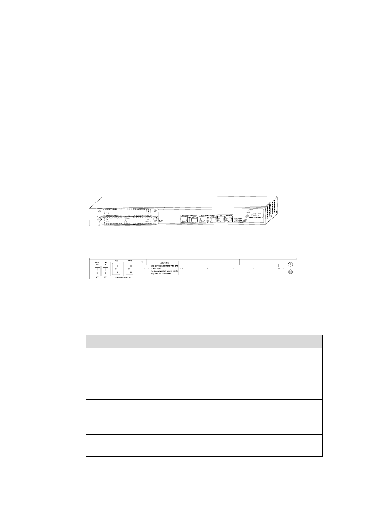
1.2.1 Appearance
Product Overview
Figure 1-1 Front panel of the H3C SecPath F1000-A
Figure 1-2 Rear panel of the H3C SecPath F1000-A
1.2.2 System Description
Table 1-1 Technical specifications of the H3C SecPath F1000-A
Item Description
MIM slot One
Fixed interface
Boot ROM 512 Kb
Two 10/100/1000 Mbps Ethernet interfaces (applicable to
both optical and electrical modes)
One auxiliary port (AUX)
One console port (CON)
DDR SDRAM
Flash memory
Default: 512 MB
Max: 1 GB
Default: 16 MB
Max: 32 MB
1-2
Page 14

Installation Manual
H3C SecPath F1000-A Firewall Chapter 1
Item Description
Product Overview
Physical dimensions
(H × W × D)
44 × 436 × 430 mm (1.7 × 17.2 × 16.9 in.), excluding the
rubber feet
Rated voltage range: 100 VAC to 240 VAC, 50 Hz or 60
Hz
AC+AC
Input
Max voltage range: 90 VAC to 264 VAC, 50 Hz or 60 Hz
Rated current: 1.5 A
power
Rated voltage range: – 60 VDC to –48 VDC
DC+DC
Max voltage range: – 72 VDC to –36 VDC
Rated current: 1.5 A
Max power
consumption
Operating temperature
Operating humidity
(non-condensing)
100 W
0°C to 40°C (32°F to 104°F
10% to 90%
)
Note:
Double data rate synchronous dynamic random access memory (DDR DSRAM) stores
the communication data with the CPU and running system.
Flash memory stores application files, exceptional information and configuration files.
Boot read only memory (Boot ROM) stores the bootstrap program files.
1.2.3 LEDs
The following table describes the LEDs on the front panel of the H3C SecPath F1000-A
and describes how to read their status.
Table 1-2 LEDs on the front panel of the H3C SecPath F1000-A
LED Description
Power supply unit (PSU) LED:
PWR0
OFF means the PWR0 is not supplying power to the device; ON
means the PWR0 is supplying power to the device.
PSU LED:
PWR1
OFF means the PWR1 is not supplying power to the device; ON
means the PWR1 is supplying power to the device.
System operating status LED:
SYS
On means the system is operating normally; OFF means the
system is operating abnormally.
1-3
Page 15

Installation Manual
H3C SecPath F1000-A Firewall Chapter 1
LED Description
Software running LED:
ACT
Blinking means the software is operating normally; OFF means
the software is faulty.
Product Overview
LINK
GE interface LED:
ON means a link is present; OFF means no link is present.
GE interface LED:
ACTIVE
ON means data are being transmitted/received on the interface;
OFF means no packets are being transmitted/received on the
interface.
1.2.4 Attributes of the Fixed Interfaces
I. Console port (CON)
Table 1-3 Attributes of the console port
Attribute Description
Connector RJ-45
Standard RS-232
Baud rate 1200 bps to 115200 bps, defaults to 9600 bps
Connected to an ASCII terminal
Services
Connected to the serial interface of a local PC running terminal
emulation software
Command line interface (CLI)
II. Auxiliary port (AUX)
Table 1-4 Attributes of the AUX port
Attribute Description
Connector RJ-45
Standard RS-232
Baud rate 1200 bps to 115200 bps
Services
Modem dial-up
Backup
1-4
Page 16
Installation Manual
H3C SecPath F1000-A Firewall Chapter 1
III. Gigabit Ethernet (GE) Interface
On the H3C SecPath F1000-A, the SRPU board provides two 10/100/1000 Mbps
Ethernet interfaces: Ethernet 0 (right) and Ethernet 1 (left), each as optical or electric
interface. The electric interface uses the RJ-45 connector and the optical interface uses
the Small Form-Factor Pluggable (SFP) connector.
Five 1000Base-FX SFP optical transceiver options are available for the H3C SecPath
F1000-A: multi-mode short-haul (850 nm), single mode medium-haul (1310 nm), single
mode long-haul (1310 nm), single mode long-haul (1550 nm), and single mode
ultra-long haul (1550 nm). They all provide LC interfaces and are hot swappable.
The following table shows the Ethernet interface attributes of the H3C SecPath
F1000-A:
Table 1-5 Attributes of the GE electrical interfaces
Attribute Description
Connector RJ-45
Product Overview
Interface type auto-MDI/MDIX
Frame format
Ethernet_II
Ethernet_SNAP
10/100/1000 Mbps auto-sensing
Operating mode
Full duplex/Half-duplex
(1000 Mbps and half-duplex cannot be
used at the same time)
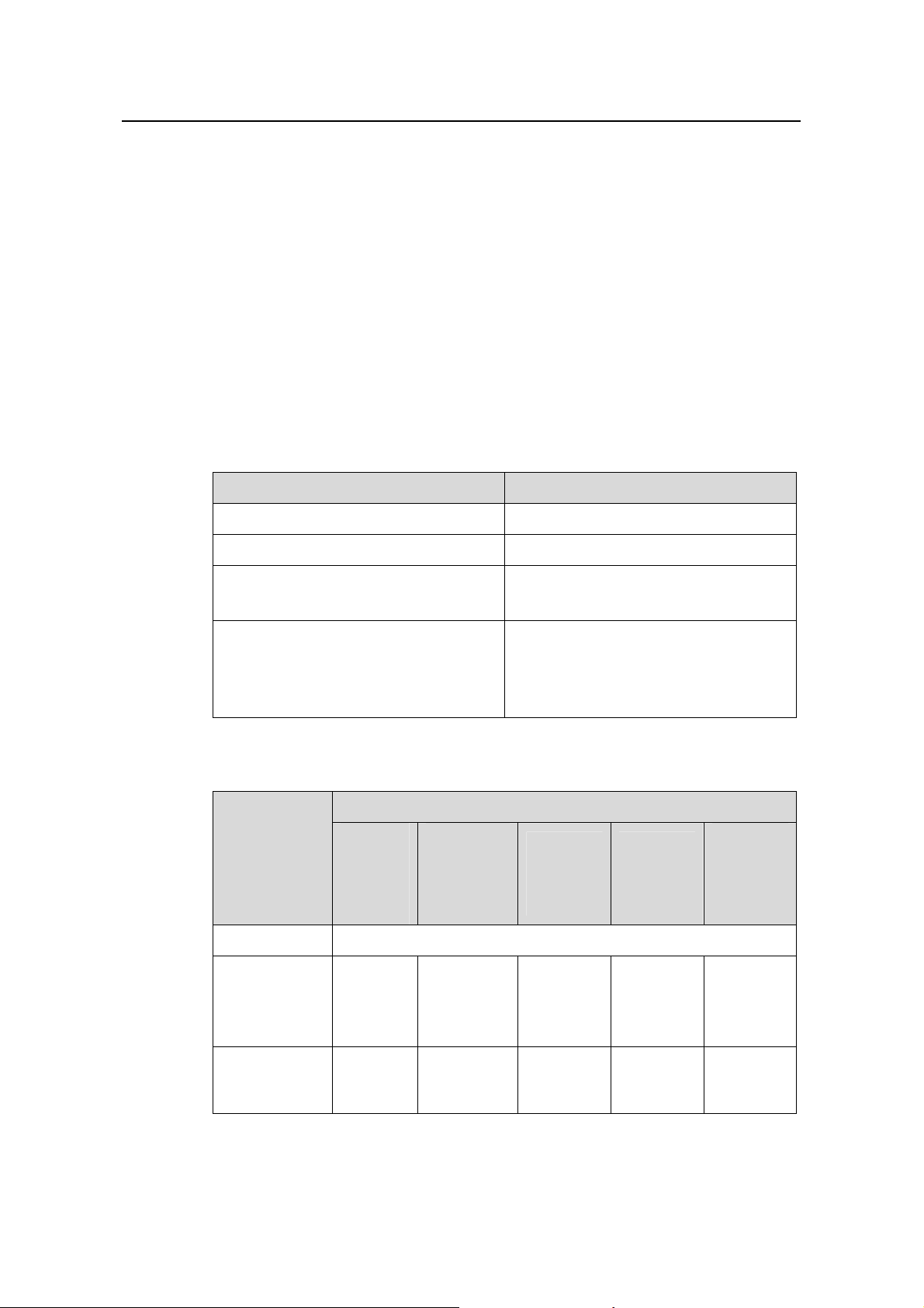
Table 1-6 Attributes of the GE optical interfaces
Description
Attribute
Multi-mo
de
short-ha
ul (850
nm)
Single
mode
medium-ha
ul (1310
nm)
Single
mode
short-haul
(1310 nm)
Connector SFP/LC
Optical fiber
62.5/125
μm
multi-mod
e fiber
9/125μm
single-mod
e fiber
9/125μm
single-mod
e fiber
Single
mode
long-haul
(1550 nm)
9/125μm
single-mod
e fiber
Single
mode
ultra-long
haul (1550
nm)
9/125μm
single-mod
e fiber
Max
transmission
distance
0.55 km
(0.34 mi)
10 km (6.21
mi)
1-5
40 km
(24.86 mi)
40 km
(24.86 mi)
70 km
(43.5 mi)
Page 17

Installation Manual
H3C SecPath F1000-A Firewall Chapter 1
Description
Product Overview
Attribute
Central
wavelength
tter
optical
power
Receiver
sensitivity
Operating
mode
Frame format
Note:
Multi-mo
de
short-ha
ul (850
nm)
Single
mode
medium-ha
ul (1310
nm)
Single
mode
short-haul
(1310 nm)
Single
mode
long-haul
(1550 nm)
Single
mode
ultra-long
haul (1550
nm)
850 nm 1310 nm 1310 nm 1550 nm 1550 nm
Min -9.5 dBm -9 dBm -2 dBm -4 dBm -4 dBm Transmi
Max 0 dBm -3 dBm 5 dBm 1 dBm 2 dBm
-17 dBm -20 dBm -23 dBm -21 dBm -22 dBm
1000 Mbps
Full duplex
Ethernet_II
Ethernet_SNAP
1.2.5 MIM
z When using optical transceivers, select those that have been approved by our
company.
z Before performing switchover between electrical/optical interfaces, you need to first
disable the rate and duplex mode configurations in the current mode (electrical or
optical), and then configure the interface after the switchover.
The H3C SecPath F1000-A provides one extended MIM slot where one of the following
MIMs can be installed:
z 1-port 10Base-T/100Base-TX Fast Ethernet interface module (1FE)
z 2-port 10Base-T/100Base-TX Fast Ethernet interface module (2FE)
z 4-port 10Base-T/100Base-TX Fast Ethernet interface module (4FE)
z 1-port 10Base-T/100Base-T/1000Base-TX Ethernet interface module (1GBE)
z 2-port 10Base-T/100Base-T/1000Base-TX Ethernet interface module (2GBE)
z 1-port 1000Base-LX/1000Base-SX optical interface module (1GEF)
z 2-port 1000Base-LX/1000Base-SX optical interface module (2GEF)
z Security socket layer encryption module (SSL)
For more information on the MIMs, see
1-6
Chapter 8 “Multifunctional Interface Module”.
Page 18

Installation Manual
H3C SecPath F1000-A Firewall Chapter 1
Product Overview
1-7
Page 19

Installation Manual
H3C SecPath F1000-A Firewall Chapter 2
Chapter 2 Preparation for Installation
2.1 Site Requirements
The H3C SecPath Series Firewalls must be used indoors. To guarantee the normal
operation and long service life of your device, install it in an environment that can meet
the requirements in the following subsections.
2.1.1 Temperature/Humidity
The equipment room must maintain adequate temperature and humidity. Long-lasting
high humidity is prone to cause bad insulation and even electricity creepage.
Sometimes the mechanical performance changes of materials, the rustiness and
corrosion of some metal parts are also likely to occur. If the relative humidity is too low,
the captive screws can become loose due to insulation washer contraction. Meanwhile,
the static is likely produced in the dry environments, jeopardizing the CMOS circuit of
the product. The higher the temperature is, the greater the damage to your device.
Long-lasting high temperature can speed up the aging of the insulation materials,
greatly lower the device reliability, and hence significantly shorten its service life.
Preparation for Installation
The following table lists the temperature and humidity requirements.
Table 2-1 Temperature/Humidity requirements in the equipment room
0°C to 40°C (32°F to 104°F)
2.1.2 Cleanness
Dust is a hazard to the operating safety of your device. The dust accumulated on the
chassis can cause electrostatic adsorption, one of the sources that cause the poor
contact of connectors or metal contact points. This not only shortens the service life of
your device but also causes communications failures. When the indoor relative
humidity is low, electrostatic adsorption is more likely to happen.
The equipment room must be free of explosion hazards and the electrical and magnetic
conductible dust as well. The contents of the dust must be limited as shown in the
following table:
Temperature Relative humidity
10% to 90% (noncondensing)
2-1
Page 20

Installation Manual
H3C SecPath F1000-A Firewall Chapter 2
Table 2-2 Limit to the content of dust in an equipment room
Substance Unit Content
≤ 3 X 10
Dust Particles/m³
(No visible dust on the
table top for three days)
Note: diameter of a dust particle ≥ 5μm
Besides the dust, there are rigorous limits on the harmful gases that can accelerate the
erosion and aging of metals, such as salts, acids, and sulfides, as shown in the
following table.
Table 2-3 Limits on the contents of harmful gases in the equipment room
Gas Maximum (mg/m3)
Preparation for Installation
4
SO
2
H2S 0.006
NH
3
Cl
2
2.1.3 ESD Prevention
Although the H3C SecPath Series Firewall is designed to be electrostatic discharge
(ESD) preventive, the card circuits and even the device can be badly damaged when
excessive static electricity is present.
On the communication network connected to your device, the static electricity mainly
comes from the outside electrical fields, such as outdoor high-voltage power cables
and lightning, and from the indoor environments, floor materials and the internal system
such as the equipment frame. To prevent damage, observe the following:
z Connect your device and the floor to the earth ground properly.
z Keep the equipment room as clean as possible.
z Maintain adequate temperature and humidity.
z Wear an ESD-preventive wrist strap and clothes when handling the circuit board.
z Place the removed circuit board upward on the ESD-preventive workbench, or into
a static shielding bag.
z Hold the circuit board by its edge when observing or moving it, avoiding direct
contact with the elements on it.
0.2
0.05
0.01
2-2
Page 21

Installation Manual
H3C SecPath F1000-A Firewall Chapter 2
2.1.4 Electromagnetic Environment
All interference sources, wherever they are from, impact the firewall negatively in the
conducted emission patterns of capacitance coupling, inductance coupling,
electromagnetic wave radiation, and common impedance (including the grounding
system) coupling. To resist the interference, make sure to:
z Take effective measures against the interference caused by the power supply grid.
z Use a grounding system or lightning protection grounding different from that for the
power supply equipment and keep them as far as possible.
z Keep the device far from strong the power radio launchers, radar launchers, and
high frequency and high-current equipment.
z Use electromagnetic shielding when necessary.
2.1.5 Lightning Protection
Although the H3C SecPath Series Firewall is designed to be lightning resistant, your
device can get damaged when excessive lightning is present. To protect your device
against lightning,
Preparation for Installation
z Ensure the chassis is connected to the earth ground.
z Ensure the earth point of the power socket is well connected to the earth ground.
z Add a lightning arrester onto the front end of the power input to better protect the
power supply from lightning strikes.
2.1.6 Mounting Rack
When installing the device in a rack, make sure that:
z There is adequate clearance between the air inlet/exhaust vents and the rack for
ventilation.
z The rack has a good ventilation system.
z The rack is firm enough to support the device and its accessories.
z The rack is well earthed.
2.2 Safety Precautions
Be sure that you observe all safety precautions when you install your device and pay
adequate attention to the following icons:
Warning appears in operation procedures that, if performed incorrectly, might
cause bodily injury to the operators or damage the device.
Caution means care should be taken in these operations during installation and
use. Improper operations may result in abnormal running of the device.
2-3
Page 22

Installation Manual
H3C SecPath F1000-A Firewall Chapter 2
Follow these safety precautions when installing or using your device:
z Keep the device far from the moisture and heat sources.
z Make sure that the device is well earthed.
z Always wear an ESD-preventive wrist strap when installing and maintaining the
SecPath 1000F, making sure the strap has good skin-contact.
z Do not hot-swap the console cable and auxiliary cable.
z Do not look directly into the fiber Tx port or the optical connector connected to it.
z You are recommended to use Uninterrupted Power Supply (UPS) for the firewall.
2.3 Unpacking Check
Check the arrived shipment against the packing list, making sure all the items are
included and in good condition. Contact your agent for shortage or wrong delivery.
2.4 Tools, Meters, and Devices
I. Tools
Preparation for Installation
z Phillips screwdriver
z Flat-blade screwdriver
z ESD-preventive wrist strap
z Static shielding bag
II. Cables
z Grounding wire and power cord
z Console cable
z Interface cable (optional)
III. Meters and devices
z HUB or LAN switch
z Console terminal (or PC)
z Multimeter
Note:
The installation tools, meters and devices are not shipped with the firewall.
2-4
Page 23
Installation Manual
H3C SecPath F1000-A Firewall Chapter 3
Chapter 3 Hardware Installation
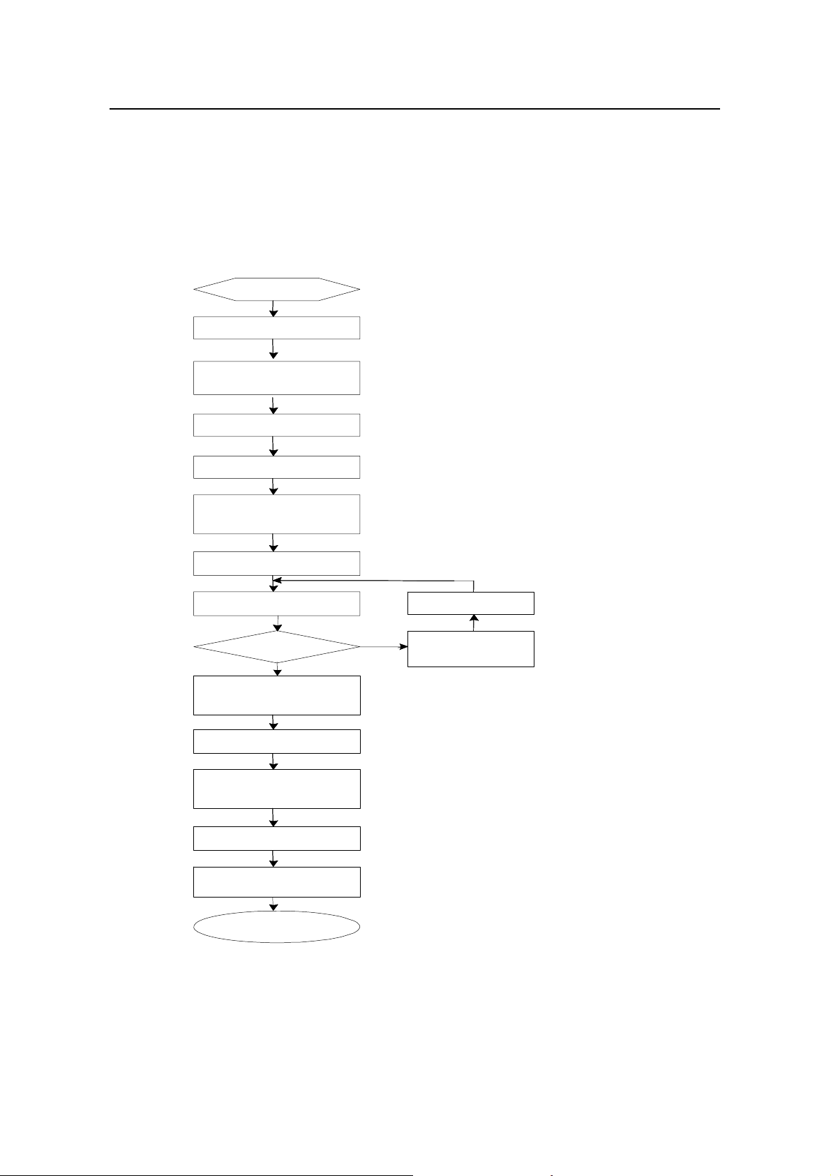
3.1 Installation Procedure
Start
Install the cabinet (optional)
Install the device at the
specified place
Connect the grounding wires
Connect the power cord
Hardware Installation
Connect the consol e
terminal to device
Verify the installation
Power up the device
Normal?
YES
Power down the device and
remove the power cord
Install MIM (optional)
Connect the Ethernet
interface
Verify the installation
Connect the power cord
/power up the device
NO
Troubleshooting
Power down the
device
End
Figure 3-1 Installation procedure
3-1
Page 24
Installation Manual
H3C SecPath F1000-A Firewall Chapter 3
Caution:
Before you install your device, make sure that:
You have read
Chapter 2 “Preparation for Installation” carefully.
The requirements in Chapter 2 are satisfied.
3.2 Mounting the Device
You can install your device on a workbench/tabletop or in a rack.
3.2.1 Tabletop/Workbench-Mounting the Device
If a 19-inch standard rack is unavailable, you can place the firewall on a clean
workbench/tabletop. To prevent any damage, observe the following:
z Ensure the table is stable and well earthed.
z Reserve the clearance of 10 cm (3.9 in.) around the device for adequate
ventilation.
z Do not place any heavy stuff on the device.
Hardware Installation
3.2.2 Rack-Mounting the Device
The firewall can be placed in a 19-inch standard rack. The following table shows its
dimensions:
Table 3-1 Dimensions of the firewall
Model
H3C SecPath F1000-A
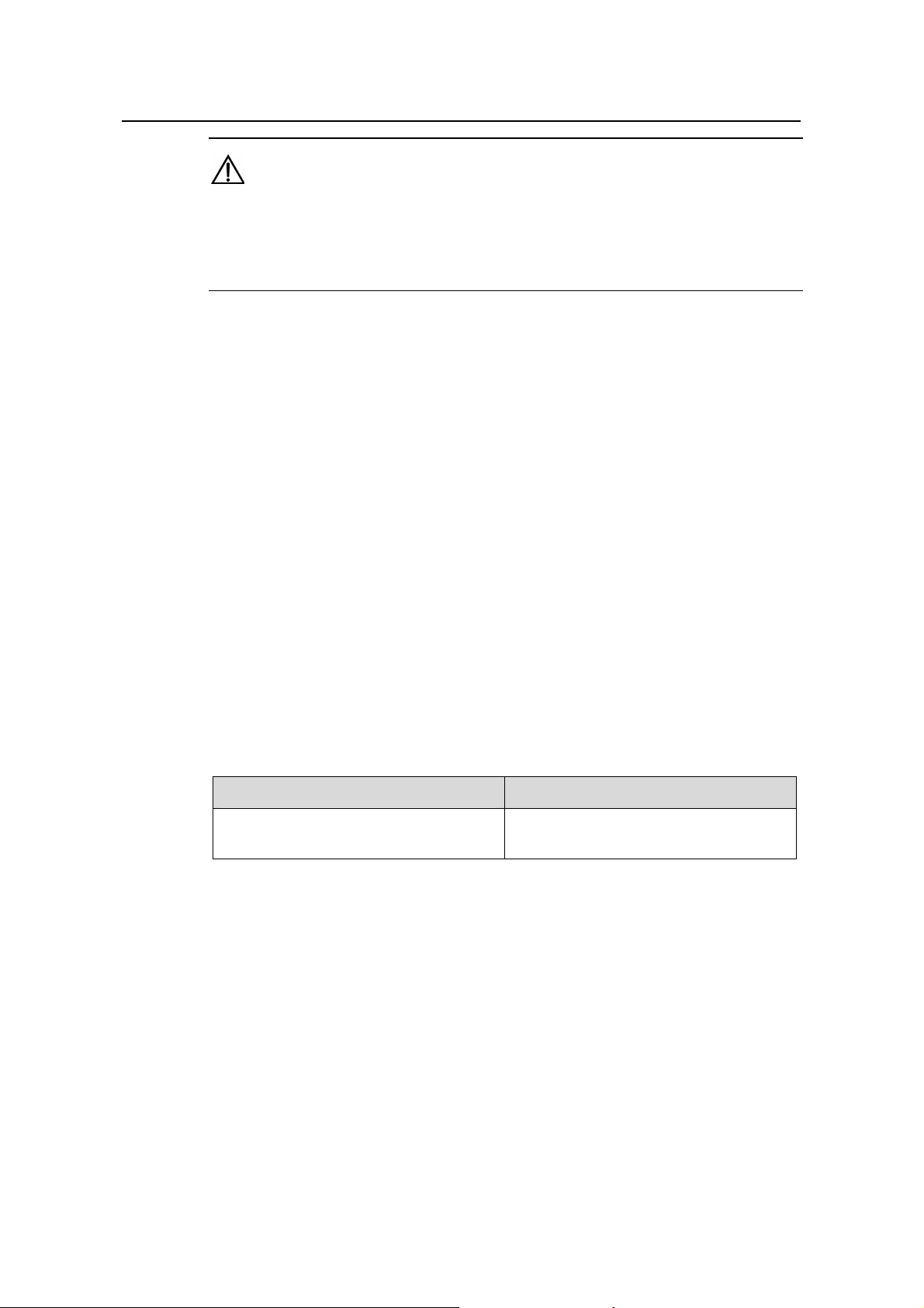
Follow these steps to install the H3C SecPath F1000-A firewall:
Step 1: Check that the rack is stable enough and properly earthed. Attach the mounting
ears to the front or rear of the chassis with screws.
Step 2: Place the device on a shelf in the rack and slide it to a proper position along the
guide rails, reserving a suitable clearance between the device and the guide rails.
Step 3: Fix the brackets to the rack posts with suitable antirust pan-head screws,
making sure that the device is securely fixed.
Dimensions (H × W × D)
44 × 436 × 430 mm (1.7 × 17.2 × 16.9
in.), excluding the rubber feet
3-2
Page 25
Installation Manual
H3C SecPath F1000-A Firewall Chapter 3
(1) Pan-head screws (4) (2) Mounting ear (3) Guide rail
Figure 3-2 Install the H3C SecPath F1000-A firewall in a rack
3.3 Installing an MIM
For details about installing MIMs, see Chapter 8 “Multifunctional Interface Modules”.
Hardware Installation
3.4 Connecting the Grounding Wires
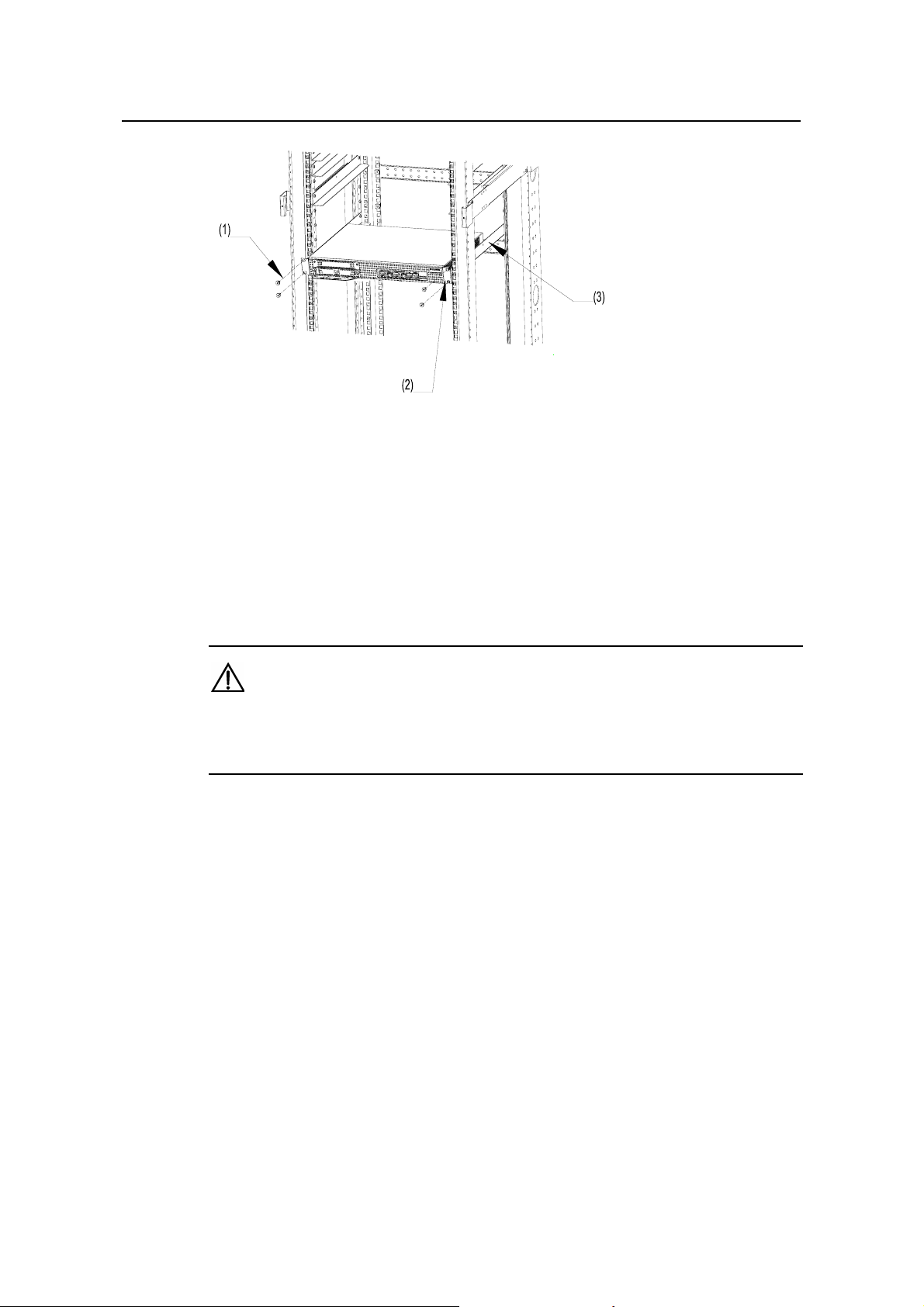
Caution:
When installing or using your device, properly connect the grounding wire for lightning
protection and anti-interference.
The H3C SecPath Series Firewall provides a grounding screw, which must be
connected to the earth ground properly to safely channel the faradic current and
leakage electricity to the ground and have the device less susceptible to
electromagnetic interference (EMI).
On the rear panel of the firewall, the grounding screw resides at the bottom right with a
grounding mark, as shown in
Figure 3-3.
3-3
Page 26

Installation Manual
H3C SecPath F1000-A Firewall Chapter 3
(1) Grounding screw
Figure 3-3 Grounding screw on the firewall
Connect this screw to the earth ground using a grounding wire. The grounding
resistance must be smaller than 5 ohm. If the device is mounted in a 19-inch standard
rack, the rack must be earthed.
Hardware Installation
Caution:
Lightning strikes can damage your device and the connected device as well. For
secure lightning protection, make sure that your device has a good ground connection
when it is operating.
3.5 Connecting to the Console Terminal
I. Console port
On the H3C SecPath Series Firewalls, one RS-232 asynchronous serial console port is
available for you to configure the device. For the attributes of the console port, refer to
the section “
II. Console cable
Console cable is an 8-wire shielded cable. At one end of the cable is an RJ-45
connector to the console port on the firewall; at the other end is a DB9 (female)
connector to the serial port of the console terminal.
1.2.4 Attributes of the Fixed Interfaces”.
Figure 3-4 illustrates a console cable:
3-4
Page 27

Installation Manual
H3C SecPath F1000-A Firewall Chapter 3
A
X3
A
Figure 3-4 Console cable assembly
III. Connecting the console cable
When configuring the firewall through a console terminal, follow these steps to connect
the console cable:
Step 1: Select a console terminal.
The console terminal can be either a standard ASCII terminal with an RS-232 serial
port, or more commonly, a PC.
Step 2: Power down the firewall and the console terminal; connect the RS-232 serial
port on the console terminal to the console port on the firewall through the console
cable.
Hardware Installation
Step 3: Verify the connection and power up the devices.
The console terminal shows the startup information of the firewall if the connection is
correct. For details, see
Chapter 4 “Booting and Configuration”.
3.6 Connecting the Ethernet Interface
I. Introduction to the Ethernet interface
The H3C SecPath F1000-A firewall provides two fixed 10/100/1000 Mbps auto-sensing
GE interfaces, each providing an optical interface and an electrical interface (one in use
at a time). For optical interfaces, SFP transceivers are used. For the available SFP
transceiver options, see
II. Ethernet cable
Electrical and optical Ethernet interfaces use different Ethernet cables for connection.
1) Cables for electrical Ethernet interfaces
For an electrical Ethernet interface, you can use a category-5 twisted-pair cable
(straight-through or crossover), as shown in
Table 1-6.
Figure 3-5:
3-5
Page 28

Installation Manual
H3C SecPath F1000-A Firewall Chapter 3
Figure 3-5 Ethernet cable assembly
Note:
In making network cables, shielded cables are preferred for the sake of
electromagnetic compatibility.
2) Cables for optical Ethernet interfaces
For an optical Ethernet interface, you can choose the appropriate fiber cable,
single-mode or multi-mode, depending on the 1000Base-FX SFP optical transceiver
you are using (see
Table 1-6 for fiber options). Because all the available optical
transceivers use LC optical connectors, your must use the fiber cable with LC fiber
connectors. All the optical transceivers are hot-swappable.
Hardware Installation
Note:
A fiber connector, as defined by the International Telecommunications Union (ITU), is a
passive component that connects two or more fiber cable segments stably but not
permanently. Fiber connectors are indispensable to an optical communication system,
making it possible to connect and disconnect optical channels.
Following are several fiber connector types:
FC: A round optical connector with screw threads
ST: A round plug-in optical connector
SC: A square optical connector
MT-RJ: A square optical transceiver
LC: A compact optical connector developed by Lucent
Note:
The fiber cable selection depends on SFP module. You must specify the desired SFP
modules when you purchase a firewall. Otherwise, the fiber cable is not provided.
3-6
Page 29

Installation Manual
H3C SecPath F1000-A Firewall Chapter 3
III. Connecting an Ethernet cable
Take the fixed 10/100/1000 Mbps Ethernet 1 port on the front panel of the H3C SecPath
F1000-A firewall for example. Follow these steps to connect its Ethernet cable:
Caution:
For each fixed Ethernet interface (for example, 10/100/1000 Mbps Ethernet 1 on the
H3C SecPath F1000-A firewall), if both of its electrical and optical ports are connected,
the electrical port is regarded as the operating port by default.
1) Connect the Ethernet electrical port
Hardware Installation
Caution:
Read the mark above the port to be connected carefully, making sure it is the correct
port.
Step 1: Connect one end of the Ethernet cable to the electrical port of the 10/100/1000
Mbps Ethernet 1 and the other end to the peer device.
Step 2: Check the status of the LINK LED for the Ethernet 1 interface. ON means the Rx
link is present. OFF means no Rx link is present; check the line for the cause.
2) Connect the optical Ethernet port
Caution:
In connecting the fiber cable, observe the following:
Do not over-bend the fiber cable. Its curvature radius must be greater than 10 cm (3.9
in.).
Ensure that the Tx and Rx ends are correctly connected.
Ensure that the fiber ends are clean.
3-7
Page 30

Installation Manual
H3C SecPath F1000-A Firewall Chapter 3
Caution:
Laser danger: never look into the optical ports that are connected to the laser. It can
harm your eyes.
Step 1: Correctly connect one end of a fiber-optic cable to the Rx port of the
10/100/1000 Mbps interface on the firewall and the other end to the Tx port on the peer
device. Connect another fiber-optic cable between the Tx port on the firewall and the
Rx port on the peer device.
Step 2: Power up the firewall and check the status of the LINK LED of the Ethernet 1
interface. On means the Rx link is present. OFF means no Rx link is present; check the
line for the cause.
3.7 Connecting a PSU
Hardware Installation
The H3C SecPath Series Firewall can be AC-powered or DC-powered. Except for PSU,
the two models are exactly the same with respect to functionalities and other features.
Note:
If both PSUs are connected, they operate in mutual backup mode.
3.7.1 Connecting an AC-Input PSU
I. AC-input PSU
AC input: 100 VAC to 240 VAC, 50 Hz or 60 Hz
Figure 3-6 illustrates the power socket on an AC-powered firewall:
3-8
Page 31

Installation Manual
H3C SecPath F1000-A Firewall Chapter 3
(1) PWR1 switch (2) PWR0 switch
(3) AC-input PWR1 (4) AC-input PWR0
Figure 3-6 Power socket on the AC-powered firewall
II. Recommended power socket
Hardware Installation
You are recommended to use a single-phase three-terminal socket with an earth
contact, which must be properly grounded. The building ground system is often buried
during the wiring engineering. Make sure that the building ground system is normal
before connecting the AC power cord.
III. Connecting an AC-input PSU
Take the H3C SecPath F1000-A firewall for example.
Step 1: Make sure that the grounding screw on the chassis is securely connected to the
earth ground.
Step 2: Make sure that the power switches are placed in the OFF position. Connect one
end of an AC power cord provided with the device to the socket of AC-input PWR0 on
the left-rear of the chassis and the other end to the AC mains supply.
Step 3: Repeat Step 2 to connect the PWR1. (Skip this step if you use only one PSU.)
Step 4: Place the PWR0 switch into the ON position.
Step 5: Place the PWR1 switch to the ON position. (Skip this step if you use only
PWR0.)
Step 6: Check that the PWR0 and PWR1 LEDs on the front panel light. ON means the
power connections are correct.
Step 7: Check that the SYS LED on the front panel is ON. ON means the hardware
system is working well.
3-9
Page 32

Installation Manual
H3C SecPath F1000-A Firewall Chapter 3
3.7.2 Connecting a DC-Input PSU
I. DC-input PSU
DC input power: – 60 VDC to – 48 VDC
II. Connecting a DC-input PSU
Take the H3C SecPath F1000-A firewall for example.
Step 1: Make sure that the PGND is securely connected to the earth ground.
Step 2: Make sure that the power switches are placed in the OFF position. Connect one
end of a DC power cord provided with the device to the socket of DC-input PWR0 on
the left-rear of the chassis and the other end to the – 48 VDC power source.
Step 3: Repeat Step2 to connect the PWR1. (Skip this step if you use only one PSU.)
Caution:
Hardware Installation
Before connecting a DC-input PSU, read the label on the power cord to be used to
make sure that you are using a DC power cord.
Step 4: Place the PWR0 switch into the ON position.
Step 5: Place the PWR1 switch to the ON position. (Skip this step if you use only
PWR0.)
Step 6: Check that the PWR0 and PWR1 LEDs on the front panel are ON. ON means
the power connections are correct.
Step 7: Check that the SYS LED on the front panel is ON. ON means the hardware
system is working well.
3.8 Verifying Installation
Each time you power up the firewall during the installation, verify that:
z The device has adequate clearance around it for heat dissipation and the
table/rack is stable enough.
z The proper power supply is used.
z The grounding wire is correctly connected.
z The device is correctly connected to other devices, such as a console terminal.
3-10
Page 33

Installation Manual
H3C SecPath F1000-A Firewall Chapter 3
Note:
Installation verification is extremely important, because the operations of the firewall
depend on its stability, grounding, and power supply.
Hardware Installation
3-11
Page 34

Installation Manual
H3C SecPath F1000-A Firewall Chapter 4
Chapter 4 Booting and Configuration
4.1 Booting
You can only configure the H3C SecPath Series Firewall through the console port when
you use it for the first time.
4.1.1 Setting up a Configuration Environment
I. Connecting the device to a console terminal
Connect the RJ-45 connector of the console cable to the console port on the firewall
and the DB9 connector to the serial port on the console terminal, as shown in
.
4-1
Booting and Configuration
Figure
To RS-232 serial interface
PC
Figure 4-1 Local configuration through the console port
H3C SecPath F1000-A
To console port
II. Setting terminal parameters
Follow these steps to set terminal parameters on the console terminal, a PC running
Windows98 for example:
Step 1: When you perform the configuration on a PC, the terminal emulations, such as
the Windows 3.1 Terminal, the HyperTerminal of Windows95/Windows98/WindowsNT,
is needed for a connection. Enter the name of the new connection and click <OK>. See
Figure 4-2.
4-1
Page 35

Installation Manual
H3C SecPath F1000-A Firewall Chapter 4
Figure 4-2 Set up a new connection
Step 2: Set the terminal parameters.
Booting and Configuration
Set the HyperTerminal parameters of Windows98 as follows:
1) Select serial interface
Select the serial interface to be used from the Connect using drop-down list as shown in
Figure 4-3. The serial interface selected here must be the one connected to the console
cable.
Figure 4-3 Select serial interface
2) Set the serial interface
The [Port Settings] tab appears as shown in
parameters as follows:
4-2
Figure 4-4, and set the serial interface
Page 36

Installation Manual
H3C SecPath F1000-A Firewall Chapter 4
z Baud rate = 9600
z Data bits = 8
z Parity = None
z Stop bits = 1
z Flow control = None
Click <OK> and the HyperTerminal window appears.
Booting and Configuration
Figure 4-4 Set communications parameters
3) Select emulation type
Choose [Properties/Settings] to enter the corresponding page and select the emulation
as VT100 or Auto detect. Click <OK> and the HyperTerminal window appears.
4-3
Page 37

Installation Manual
H3C SecPath F1000-A Firewall Chapter 4
Booting and Configuration
Figure 4-5 Settings tab
4.1.2 Powering up the Firewall
I. Checking before power-up
Before powering up the firewall, check that:
z Both the power cord and the grounding wire are correctly connected.
z Proper power supply is used.
z The console cable is correctly connected.
z The console terminal (or PC) has been started and the related parameters have
been set on it.
Caution:
Locate the emergency power-off switch in the room before powering up the firewall.
Then, if an accident occurs, you can quickly shut off the power.
II. Powering up the Firewall
z Turn on the switch of the mains supply.
z Place the power switch(es) on the device into the ON position.
4-4
Page 38

Installation Manual
H3C SecPath F1000-A Firewall Chapter 4
III. Checking/Operating after power-up
After powering up the firewall, check that:
z The ventilation system is operating well.
After powering up the firewall, you can hear the sound of the fan blade spinning and feel
the airflow when you put your hands close to the air vents.
z The LEDs on the front panel of the chassis are in normal state.
Booting and Configuration
See the section
z The console terminal display is correct.
After powering up the firewall, you can see the startup interface on the console terminal
(see the section “
(POST), press <Enter> as prompted. When “<H3C>” is displayed, you can proceed to
configure the firewall.
4.1.3 Booting Process
After being powered up, the firewall first runs the Boot ROM program. The terminal
screen displays the following system information:
Note:
The message displayed on the terminal may vary with Boot ROM versions.
**************************************************
* *
* H3C SecPath Series Gateway Boot ROM V1.17 *
* *
**************************************************
Copyright(C) 2004-2007 by Hangzhou H3C Technologies Co.,Ltd.
Compiled at Wed Apr 12 17:39:36 CST 2006
Testing memory...OK!
512M bytes DDR SDRAM Memory
16M bytes Flash Memory
Hardware Version is 3.0
CPLD Version is 2.0
Press Ctrl-B to enter Boot Menu
1.2.3 “LEDs” for more information on LED state.
4.1.3 Booting Process”). After the system passes Power-On Self-Test
4-5
Page 39

Installation Manual
H3C SecPath F1000-A Firewall Chapter 4
Press <Ctrl+B> to enter the Boot menu. Otherwise, the system starts decompressing
the program.
Note:
To enter the Boot Menu, you must press <Ctrl+B> within three seconds after the prompt
“Press Ctrl-B to Enter Boot Menu…” appears.
The system starts decompression and initialization, and displays:
Press Ctrl-B to enter Boot Menu
System is self-decompressing............................................
System is starting...
User interface Con 0 is available.
Press ENTER to get started.
Booting and Configuration
Press <Enter>. The system displays (if login authentication is not enabled):
<H3C>
The prompt indicates that the firewall enters user view and is ready for your
configuration.
4.2 Configuration Fundamentals
4.2.1 Basic Configuration Procedures
Following are the basic steps that you can follow to configure your firewall:
Step 1: Figure out detailed networking requirements, including networking objectives,
the role of the firewall in the network, transmission medium, security policy, and
network reliability.
Step 2: Draw a network topology based on the requirements.
Step 3: Configure IP addresses of the interfaces on the firewall.
Step 4: Configure routes, and if a dynamic routing protocol is enabled, the parameters
related to the protocol.
Step 5: Configure security settings as required.
Step 6: Configure reliability settings as required.
For more information on the configuration of protocols and functions for the firewall, see
the Operation Manual and Command Manual of the corresponding product.
4-6
Page 40

Installation Manual
H3C SecPath F1000-A Firewall Chapter 4
4.2.2 Command Line Interface
I. Features of the CLI
The CLI of the firewall offers lots of configuration commands for you to configure and
manage the firewall. The CLI allows you to:
z Configure the device through the console port at the local.
z Telnet to access and manage the local and remote devices.
z Get online help whenever you enter <?>.
z Test network connectivity quickly with network diagnostic tools, such as tracert
and ping.
z Have detailed debugging information for network troubleshooting.
z Enter a command by only entering the conflict-free keyword portion, because the
CLI interpreter supports fuzzy keyword search. For example, you simply need to
enter dis for the display command.
II. CLI
Booting and Configuration
In system view, all the commands are put into several groups for the convenience of
management, each being associated to a view. You can switch between the views by
executing the proper commands. In normal circumstances, you can only execute the
commands appropriate to the view that you access. However, you are allowed to
execute in any view some commands in common use, such as ping, display
current-configuration, and interface.
4-7
Page 41

Installation Manual
H3C SecPath F1000-A Firewall Chapter 5
Chapter 5 Software Maintenance
5.1 Introduction
The firewall maintains three types of files:
z Boot ROM program files
z Application program files
z Configuration files
The software maintenance mainly involves upgrading/downloading Boot
ROM/application program files and uploading/downloading configuration files.
5.1.1 Boot Menu
This section introduces the Boot menu that you use in maintaining the software of the
firewall.
Software Maintenance
Set up a configuration environment as shown in
Figure 4-1 and then boot the firewall.
Press <Ctrl+B> when the system prompts “Press Ctrl-B to enter Boot Menu”. The
system displays:
Please input Boot ROM password :
Caution:
z Press <Ctrl+B> within three seconds after the prompt “Press Ctrl-B to Enter Boot
Menu...” appears to access the Boot Menu. Otherwise, the system starts
decompressing the program.
z If you want to access the Boot menu after the system starts decompressing the
program, you need to reboot the firewall.
Type the correct password and press <Enter>. (If no Boot ROM password is configured,
just press <Enter>.) The system accesses the following Boot menu:
I. Boot menu of the H3C SecPath F1000-A firewall
Boot Menu:
1: Download application program with XMODEM
2: Download application program with NET
3: Display file in flash
4: Delete file from flash
5-1
Page 42

Installation Manual
H3C SecPath F1000-A Firewall Chapter 5
5: Start up and ignore configuration
6: Enter debugging environment
7: Boot Rom Operation Menu
8: Do not check the version of the software
9: Exit and reboot
Enter your choice(1-9):
Note that:
z To download an application program using XModem, see section 5.1.2
“Upgrading the Application and Boot ROM Programs Using XModem”.
z In downloading an application program using the Ethernet, only TFTP is available
for the H3C SecPath F1000-A firewall. See section
Application Program Using TFTP
z If option 5 is selected, the system starts up with the initial configurations.
z If option 8 is selected, the system ignores the software version of the Boot ROM
” for the procedures.
5.1.4 “Upgrading an
program, its extended segment, and application program for backward
compatibility. If you fails to upgrade the software because the system decides that
you are using an “invalid version” even when the correct version is used, you can
use the option 7 to ignore the version check during a software upgrading. Note that
this option works only once when you select it. The system resumes version check
after you reboot the firewall.
Software Maintenance
II. Boot ROM submenu of the H3C SecPath F1000-A firewall
As mentioned earlier, you can select 7 in the Boot menu to enter the Boot ROM
submenu as follows:
Boot ROM Operation Menu:
1: Download Boot ROM with XModem
2: Download Extended Segment of Boot ROM with XModem
3: Restore Extended Segment of Boot ROM from FLASH
4: Backup Extended Segment of Boot ROM to FLASH
5: Exit to Main Menu
Enter your choice(1-5):
The menu provides approaches to Boot ROM upgrade, backup, and restoration. See
sections
and
5.1.2 “Upgrading the Application and Boot ROM Programs Using XModem”
5.1.3 “Backing up and Restoring the Extended Segment of the Boot ROM” for the
procedures.
5-2
Page 43

Installation Manual
H3C SecPath F1000-A Firewall Chapter 5
Software Maintenance
Caution:
You are recommended to upgrade the software of the firewall under the guidance of
support engineers. In addition, when upgrading the firewall, make sure the version of
the Boot ROM software is consistent with that of the application program.
5.1.2 Upgrading the Application and Boot ROM Programs Using XModem
You can use the console port to upgrade the software using XModem without the need
of setting up a configuration environment.
I. Upgrading an application program
Step 1: Enter the Boot menu (see section 5.1.1 “Boot Menu”) and enter 1 to download
an application program using XModem. The firewall supports the following download
speeds:
Downloading application program from serial ...
Please choose your download speed:
1: 9600 bps
2: 19200 bps
3: 38400 bps
4: 57600 bps
5: 115200 bps
6: Exit to Main Menu
Enter your choice(1-6):
Step 2: Choose an appropriate downloading speed (for example, 115200 bps by
entering 5). The following message appears:
Download speed is 115200 bps. Change the terminal's speed to 115200 bps, and
select XModem protocol. Press ENTER key when ready.
Step 3: Change your terminal’s baud rate (see Figure 4-4) to the same baud rate for
software downloading (115200 bps in this example). After that, disconnect the terminal
([Dial-in/Disconnect]), reconnect it ([Dial-in/Dialing]), and press <Enter> to start
downloading. The system displays:
Downloading ... CCCCC
5-3
Page 44

Installation Manual
H3C SecPath F1000-A Firewall Chapter 5
Note:
The new baud rate takes effect only after you reconnect the terminal emulation
program.
Step 4: Select [Transmit/Send File] in the terminal window. The following dialog box
pops up:
Software Maintenance
Figure 5-1 Send File dialog box
Step 5: Click <Browse>. Select the application file to be downloaded and set protocol to
XModem. Click <Send>. The following interface pops up:
Figure 5-2 Sending File interface
Step 6: After completing the downloading, the system begins writing data to the Flash,
and then displays the following information in the terminal interface, indicating the
completion of the downloading:
XModem download completed, Packet length 8790321 bytes.
System file length 7868992 bytes, http.zip file length 921329 bytes.
5-4
Page 45

Installation Manual
H3C SecPath F1000-A Firewall Chapter 5
Writing file flash:/system to FLASH...
Please wait, it may take a long time
################################################
Writing into Flash Succeeds.
Writing file flash:/http.zip to FLASH...
Please wait, it may take a long time
##########################################################################
######
#########
Writing into Flash Succeeds.
Please use 9600 bps.Press <ENTER> key to reboot the system.
Restore the speed of the console terminal to 9600 bps as prompted, disconnect and
reconnect the terminal. The system starts up normally.
II. Upgrading the Boot ROM program
Step 1: Enter the Boot Menu (see the section “5.1.1 Boot Menu”) and select 7 to enter
the Boot ROM operation submenu.
Software Maintenance
Step 2: Enter 1 in the Boot ROM operation submenu to download the Boot ROM
program using XModem. Several speed options are available for you. The subsequent
steps are the same as those described in section
program
”.
I. “Upgrading an application
Caution:
You cannot restore the Boot ROM program on site if you fail to upgrade the entire Boot
ROM program. Therefore, you must not upgrade the entire Boot ROM program unless
necessary and under direction of support engineers.
III. Upgrading the extended segment of the Boot ROM
Step 1: Enter the Boot Menu (see section 5.1.1 “Boot Menu”) and select 7 to enter the
Boot ROM operation submenu.
Step 2: Select 2 in the Boot ROM operation submenu to upgrade the extended segment
of the Boot ROM using XModem. Several speed options are available for you. The
subsequent steps are the same as those described in section
application program
”.
5.1.2 I. "Upgrading an
5-5
Page 46

Installation Manual
H3C SecPath F1000-A Firewall Chapter 5
Software Maintenance
Caution:
This upgrade approach is only used to upgrade a portion of the Boot ROM program, so
you can make a second attempt once errors occur.
5.1.3 Backing up and Restoring the Extended Segment of the Boot ROM
I. Backing up the extended segment of the Boot ROM to the Flash
Follow these steps to back up the extended segment of the Boot ROM:
Step 1: Enter the Boot Menu (see section
5.1.1 “Boot Menu”) and select 7 to enter the
Boot ROM operation submenu.
Step 2: Select 4 in the operation submenu to copy the current extended segment of the
Boot ROM to the Flash.
Backup Extended Segment, are you sure?[Y/N]
Enter Y. The system starts backing up the extended segment.
If the backup attempt is successful, the following message appears:
Writing to FLASH.Please wait...####
Backuping Boot ROM program to FLASH successed!
Step 3: When the Boot submenu appears again, select 5 to exit and reboot the firewall.
II. Restoring the extended segment of the Boot ROM from the Flash
If faults occur to the extended segment of the Boot ROM or you upgrade it wrongly, you
can restore the extended segment of the Boot ROM from the Flash to the Boot ROM by
taking these steps:
Step 1: Enter the Boot Menu (see section
5.1.1 “Boot Menu”), and select 7 to enter the
Boot ROM operation submenu.
Step 2: Select 3 in the operation submenu to restore the extended segment of the Boot
ROM from the Flash.
Restore Extended Segment, are you sure?[Y/N]
Enter Y. The system starts restoring the extended segment.
If the operation is successful, the system displays:
Writing to Boot ROM.Please wait...######
Restoring Boot ROM program successed!
Step 3: When the Boot submenu appears again, select 5 to exit and reboot the firewall.
5-6
Page 47

Installation Manual
H3C SecPath F1000-A Firewall Chapter 5
5.1.4 Upgrading an Application Program Using TFTP
Upgrade an application program with net is to download the application program using
an Ethernet interface. In this approach, the firewall is the client that needs to be
connected to the TFTP server using one of its fixed Ethernet interfaces.
Caution:
The H3C SecPath Series Firewall does not provide TFTP server programs. You should
purchase and install one by yourself.
The H3C SecPath F1000-A can only act as the TFTP client, so you can only upgrade
an application program using TFTP, shown as follows:
z Start the TFTP server
z Start the TFTP server on the PC connected to the Ethernet interface on the
SecPath 1000F and set the path to the file to be downloaded.
z Configure the SecPath 1000F
Software Maintenance
Step 1: Start the firewall and enter the Boot menu (see section
5.1.1 “Boot Menu”).
Select 2 to enter the Net Port Download Menu. The system displays the following
message:
Net Port Download Menu:
1: Change Net Parameter
2: Download From Net
3: Exit to Main Menu
Enter your choice(1-3): 1
Step 2: Select 1 to configure the network interface parameters (including the interface
in use and the IP address and subnet mask of the interface) and the TFTP server
parameters (including the IP address of the Ethernet interface on the TFTP server and
the file name of the application program).
Change Download parameter
Download device ETH0
Download file(Max 60 char) :system
IP address of ETH0 :192.168.1.15
Subnet mask for ETH0 :255.255.255.0
IP address of the server :192.168.1.10
IP address of the gateway :10.110.95.117
5-7
Page 48

Installation Manual
H3C SecPath F1000-A Firewall Chapter 5
Caution:
z The upgrade should be performed through interface ETH0 on the firewall.
z The item “IP address of the server: [192.168.1.10]” must be set to the IP address of
the TFTP server connected to the Ethernet interface on the firewall.
z You are recommended to configure the IP addresses of the TFTP server network
interface and that of the ETH0 on the firewall into the same network segment.
Step 3: After you input the last parameter value, the system displays the following
message and returns to the Net Port Download Menu:
Saving config, please wait...OK!
Net Port Download Menu:
1: Change Net Parameter
2: Download From Net
3: Exit to Main Menu
Enter your choice(1-3): 2
Software Maintenance
Step 4: Select 2 to download the application program using TFTP. The system displays
the following message:
Starting the TFTP download...
..........................................................................
.......................
TFTP download completed, Packet length 8790321 bytes.
System file length 7868992 bytes, http.zip file length 921329 bytes.
Writing file flash:/system to FLASH...
Please wait, it may take a long time
####################################################################
Writing into Flash Succeeds.
Writing file flash:/http.zip to FLASH...
Please wait, it may take a long time
##########################################################################
######
#########
Writing into Flash Succeeds.
The downloading is successful. Press <Enter> to reboot the system.
5-8
Page 49

Installation Manual
H3C SecPath F1000-A Firewall Chapter 5
5.1.5 Uploading/Downloading a Program/File Using FTP
The H3C SecPath Series Firewalls can act as the FTP server. Any FTP clients (local or
remote) connected to the firewall can update configuration files or upgrade
application/Boot ROM programs using FTP. A user can upload/download configuration
files and application programs after passing the authentication. The following
subsections describe the procedures.
Note:
Upload is to transfer files from an FTP client to the firewall, that is, the put operation.
Download is to transfer files from the firewall to an FTP client, that is, the get operation.
I. Setting up an uploading/downloading environment
z Set up a local uploading/downloading environment using FTP
Software Maintenance
H3C SecPath F1000-A (FTP Server )
10.110.10.13/24
LAN
Ethe
rnet interface
10.
P C
(FTP Client)
110.10.10/24
Figure 5-3 Set up an environment for local uploading/downloading using FTP
Step 1: Connect the PC to an Ethernet interface on the firewall.
Step 2: Assign an IP address, 10.110.10.10 for example, to the Ethernet interface on
the firewall.
Step 3: Assign an IP address, 10.110.10.13 for example, to the Ethernet interface on
the PC.
Step 4: Copy the application program/Boot ROM/configuration file to a directory, “C:\
version” for example.
5-9
Page 50

Installation Manual
H3C SecPath F1000-A Firewall Chapter 5
Caution:
The IP addresses assigned to the network interfaces of the PC and the firewall must
reside on the same network segment.
z Set up a remote uploading/downloading environment using FTP
H3C SecPath F1000-A (FTP Server)
H3C SecPath F1000-A (FTP Server)
H3C SecPath F1000-A (FTP Server)
10.110.20.13/24
10.110.20.13/24
10.110.20.13/24
PC
PC
PC
(FTP Client)
(FTP Client)
(FTP Client)
Router
Router
Router
WAN
WAN
WAN
Et
hernet interface
Et
hernet interface
Et
hernet interface
1
0.110.10.10/24
1
0.110.10.10/24
1
0.110.10.10/24
Software Maintenance
Figure 5-4 Set up an environment for remote uploading/downloading using FTP
Step 1: Connect the PC to an interface on the firewall through the WAN. The PC and
the firewall can reside on different network segments.
Step 2: Copy the application program/Boot ROM/configuration file to a directory,
“C:\version” for example.
II. Enabling the FTP server
Follow these steps under the direction of service engineers.
Step 1: Configure an authentication method.
Note:
You can configure AAA authentication as needed. For more information, see section
“AAA and RADIUS Configurations” in the Operation Manual and Command Manual of
the corresponding product.
Step 2: Add the username and password.
[VPNGateway] local-user VPNGateway
VPNGateway is the username.
Step 3: Add the password.
[VPNGateway-luser-vpngateway] password simple 123
Step 4: Add the service type and specify the FTP directory.
5-10
Page 51

Installation Manual
H3C SecPath F1000-A Firewall Chapter 5
[VPNGateway-luser-vpngateway] service-type ftp ftp-directory flash:
Step 5: Add an authority level.
[VPNGateway-luser-vpngateway] level 3
Step 6: Enable the FTP server.
[VPNGateway] ftp-server enable
After the FTP server is enabled and the user is added onto the firewall, any FTP client
program can use the username and password to log onto the FTP server.
III. Uploading/Downloading an application program/configuration file and
uploading the Boot ROM program
Step 1: In the DOS environment, access the directory containing the application
program/Boot ROM/configuration file. Execute the ftp command to set up an FTP
connection with the firewall, for example:
C:\version\ftp 10.110.10.10
If the connection is set up, the following message appears (taking Windows98 for
example):
Software Maintenance
Connected to 10.110.10.10
220 FTP server ready on VPNGateway at
User(10.110.10.10:(none)):
Step 2: Log onto the FTP server using the username and password set on the SecPath
1000F.
User(10.110.10.10:(none)): VPNGateway
331 Password required for ftp
Password:
230 User ftp logged in
ftp>
Appearance of the prompt “ftp>” indicates that you can begin uploading/downloading
the desired file.
Step 3: Upload/Download the application program/configuration file/Boot ROM.
Note:
On the firewall, the default name of the application program is "system”, the
configuration file “config.cfg”, the extended segment of the Boot ROM “bootrom”, and
the entire Boot ROM “bootromfull”.
z Upload the application program/Boot ROM/configuration file
ftp> put
5-11
Page 52

Installation Manual
H3C SecPath F1000-A Firewall Chapter 5
local file
remote file
Upon the completion of uploading, the prompt “ftp>” appears again. Enter dir to view
the name and size of the uploaded file on the firewall. It has the same size as the
original file on the host if the uploading is successful.
Caution:
z When using FTP to upgrade the application program, make sure that the firewall
has enough flash memory. If the memory is not enough, you need to use the delete
/unreserved command to permanently delete old version files or other files to save
the memory space; otherwise, new files cannot be uploaded.
z The Boot ROM upgrade is not complete after the Boot ROM program is uploaded
using the put command. To complete the upgrade, use the upgrade bootrom [ full ]
command to decompress the bootrom/bootromfull program from the root directory
in the Flash and write it to the Boot ROM. After that you have completed the upgrade
of Boot ROM.
z After uploading the application program into the flash memory, you need to rename
the program file to “system” to make the program take effect at next startup.
z After uploading configuration files into the flash memory, you need to rename the file
to “config.cfg” to make the files take effect at next startup of the system, or use the
startup saved-configuration command to set the configuration files used for next
startup.
Software Maintenance
z Download an application program/configuration file
ftp> get
remote file
local file
Step 4: Upon the completion of the uploading/downloading, quit the FTP client
program.
ftp>quit
IV. Detaching the Web file
When the downloading using FTP is completed, the Web file is included in the
application program. You need to detach it from the application program using the
detach command.
<VPN Gateway> detach system
System file length 7856557 bytes, http file length 834724 bytes.
<VPN Gateway> dir
5-12
Page 53

Installation Manual
H3C SecPath F1000-A Firewall Chapter 5
Directory of flash:/
0 -rw- 8691281 Jun 16 2009 06:46:36 system
1 -rw- 1830 Jun 17 2009 07:47:16 config.cfg
2 -rw- 834724 Jun 18 2009 02:22:39 http.zip
If the Web file is not included, the system gives the corresponding prompt. The Web file
name defaults to http.zip.
5.1.6 Modifying Boot ROM Password
You can use the Boot menu of the firewall to change the Boot ROM password.
Start the firewall. When “System starts booting” appears on the configuration terminal,
press <Ctrl+D>, and then the system prompts:
Please input Boot ROM password :
Software Maintenance
Caution:
z To enter the Boot menu, you must press <Ctrl+D> within three seconds after the
“System starts booting” prompt appears on the configuration terminal; otherwise,
the system starts decompressing the program.
z You need to restart the firewall if you want to enter the Loader menu after entering
the Boot ROM extended segment.
After entering the correct password, press <Enter>to enter the Boot menu (press
<Enter> directly if the password is not set), and the system displays the information as
follows:
Boot Menu:
1: Download Boot ROM with XModem
2: Download Extended Segment of Boot ROM with XModem
3: Modify Boot ROM password
4: System booting from Flash
5: Do not check the version of Extended Segment of Boot ROM
6: Exit and reboot
Enter your choice(1-6):
Following is the description on the options of Boot menu:
z 1: Download Boot ROM with XModem
z 2: Upgrade the extended segment of Boot ROM with XModem
z 3: Modify Boot ROM password
5-13
Page 54

Installation Manual
H3C SecPath F1000-A Firewall Chapter 5
z 4: Boot the system from flash (This option requires backing up the extended
segment of Boot ROM in flash, refer to
z 5: The system ignores the software version of the Boot ROM program, its
5.1.3 for details.)
extended segment, and application program for backward compatibility. If you fail
to upgrade the software because the system decides that you are using an “invalid
version” even when the correct version is used, you can use this option to ignore
the version check during a software upgrading. Note that this option works only
once when you select it. The system resumes version check after you reboot the
firewall.
z 6: Exit from the Loader menu and restart the firewall.
Select 3 in the Boot menu to change the Boot ROM password, and the system prompts:
Modify Boot ROM password, are you sure?[Y/N]y
Please input new password(Max 32 char) :
Retype the new password(Max 32 char) :
Saving the password... Success!
Software Maintenance
Note:
The password can contain up to 32 characters.
5.1.7 Resetting a Lost Password
Contact our support engineers in case of Boot ROM or user password loss. They can
help your access the firewall to set a new password.
5-14
Page 55

Installation Manual
H3C SecPath F1000-A Firewall Chapter 6
Chapter 6 Hardware Maintenance
6.1 Preparing Tools
z Phillips screwdriver
z Flat-blade screwdriver
z ESD-preventive wrist strap
z Static shielding bag
Note:
These tools are not shipped with the firewall, so you need to prepare them yourself.
Hardware Maintenance
6.2 Opening the Chassis Cover
Step 1: Power down the firewall and remove the power cords.
Step 2: Remove the interface cables from the front of the chassis, except for the
grounding wire.
Step 3: Place the firewall on a flat table, with the rear forward. Use a Phillips screwdriver
to remove the two captive screws securing the cover at the rear of the chassis.
Step 4: Undo the two captive screws securing the cover at each side of the chassis.
Step 5: Raise the cover to such a height that the edge of the cover is separated from the
bottom of the chassis.
Step 6: Pull the cover towards you until the tabs on the edge of the cover are separated
from the front panel. Put the cover away.
6-1
Page 56

Installation Manual
H3C SecPath F1000-A Firewall Chapter 6
(1)
(1)
(2)
Hardware Maintenance
(1)
(1) Remove the six screws (2) Pull it out towards this direction
Figure 6-1 Open the chassis
Caution:
z Do not replace the hardware unless necessary and under the guidance of support
engineers.
z There is an anti-dismantle seal on a screw on the chassis. You must keep the seal
intact before your sales representative maintains the firewall. So you must contact
your sales representative to obtain the permission before you open the chassis. The
company is not liable for any damage or consequence resulted from users'
operation without permission.
z Ensure that the firewall has no electricity before servicing the device to avoid bodily
injuries and device damages.
z Wear an ESD-preventive wrist strap when servicing the device, making sure it has
good skin-contact.
z You must use the SDRAMs provided by H3C. Otherwise, anomalies might occur to
the device.
6.3 Replacing a DDR SDRAM
Following are the storage media available for the firewall:
z DDR SDRAM (Synchronous Dynamic RAM): where the programs of the firewall
are running.
z Flash memory: stores the programs and configuration files of the firewall.
z Boot ROM: stores the boot and initialization programs of the firewall.
6-2
Page 57

Installation Manual
H3C SecPath F1000-A Firewall Chapter 6
Hardware maintenance mainly involves DDR SDRAM replacement.
Follow this maintenance flow to replace a DDR SDRAM:
Start
Start
Start
Start
Start
Start
Start
Start
Prepare the tools
Prepare tools
Prepare the tools
Prepare tools
Prepare the tools
Prepare tools
Prepare the tools
Prepare tools
Open the chassis
Open the chassis
Open the chassis
Open the chassis
Open the chassis
Open the chassis
Open the chassis
Open the chassis
Verify th
e position of
Verify th
e position of
Verify th
e position of
Verify th
Locate the DDR SDRAM
Locate the DDR SDRAM
Locate the DDR SDRAM
Locate the DDR SDRAM
RemoveD the
RemoveD the
RemoveD the
RemoveD the
Remove the old DDR SDRAM
Remove the old DDR SDRAM
Remove the old DDR SDRAM
Remove the old DDR SDRAM
e position of
DDR SD
DDR SD
DDR SD
DDR SD
DR SDRAM
DR SDRAM
DR SDRAM
DR SDRAM
RAM
RAM
RAM
RAM
old
old
old
old
Hardware Maintenance
Install th
Install th
Install th
Install th
Install a new DDR SDRAM
Install a new DDR SDRAM
Install a new DDR SDRAM
Install a new DDR SDRAM
Close the chassis
Close the chassis
Close the chassis
Close the chassis
Close the chassis
Close the chassis
Close the chassis
Close the chassis
Complete h
Complete h
Complete h
Complete h
DDR SD
DDR SD
DDR SD
DDR SD
End
End
End
End
maint
maint
maint
maint
e new
e new
e new
e new
RAM
RAM
RAM
RAM
ardware
ardware
ardware
ardware
enance
enance
enance
enance
Figure 6-2 DDR SDRAM maintenance flow
A DDR SDRAM is a mainboard component that you can expand and replace as needed.
Generally, you need to expand a DDR SDRAM for:
z Upgrading the Comware.
z Providing an adequate memory size for retaining a large routing table or
processing tasks that consume huge memory resources.
When booting the firewall, you can see the following messages:
**************************************************
* *
* H3C SecPath Series Gateway Boot ROM V1.17 *
* *
**************************************************
Copyright(C) 2004-2007 by Hangzhou H3C Technologies Co.,Ltd.
Compiled at Wed Apr 12 17:39:36 CST 2006
Testing memory...OK!
512M bytes DDR SDRAM Memory
6-3
Page 58

Installation Manual
H3C SecPath F1000-A Firewall Chapter 6
16M bytes Flash Memory
Hardware Version is 3.0
CPLD Version is 2.0
Press Ctrl-B to enter Boot Menu
“512M bytes DDR SDRAM” means that the firewall is installed with a DDR SDRAM of
512M bytes.
Note:
Note that there is a limit on the times that you can install a DDR SDRAM in a memory
bank.
6.3.1 Locating the DDR SDRAMs on the Mainboard
Hardware Maintenance
When removing/installing a DDR SDRAM, make sure to identify the type of mainboard
and the exact position of the DDR SDRAM. See the following table for the types of
memory used in the firewall and the configuration:
Table 6-1 Memory specifications
Item Specifications
Memory type DDR SDRAM
Max size of an identifiable memory bank (MB) 512
Expansion limit Expandable to 1 GB
The following figure shows where the DDR SDRAMs, Flash, and Boot ROM are located
on the mainboard:
6-4
Page 59

Installation Manual
H3C SecPath F1000-A Firewall Chapter 6
Figure 6-3 Position of the DDR SDRAMs, Flash, and Boot ROM on the mainboard
Each DDR SDRAM has one positioning recess at its bottom for correct orientation.
When installing a DDR SDRAM into a memory bank, press the positioning recess into
the pin in the bank.
Hardware Maintenance
6.3.2 Removing a DDR SDRAM
Step 1: Locate the DDR SDRAM to be replaced on the mainboard.
Step 2: Press the clips at both sides of the DDR SDRAM bank outward with appropriate
pressure, till the DDR SDRAM ejects from the bank.
Figure 6-4 Remove a DDR SDRAM
Step 3: Hold the DDR SDRAM by its non-conductive edge and take it out of the bank.
Place it in a static shielding bag to avoid ESD damages.
6-5
Page 60

Installation Manual
H3C SecPath F1000-A Firewall Chapter 6
Caution:
z Hold the DDR SDRAM only by its non-conductive edge, because it is prone to ESD
and could be damaged by incorrect operations.
z You need to exercise some strength to pull the DDR SDRAM out of its bank but do
not overdo it.
z Do not touch the components on the DDR SDRAM by hands.
z The marks “DDR SDRAM1” and “DDR SDRAM2” in Figure 6-3 do not mean the
DDR SDRAMs are divided into basic and extended DDR SDRAMs; they are
identical.
6.3.3 Installing a DDR SDRAM
Follow these steps to install a DDR SDRAM.
Hardware Maintenance
Step 1: Locate the memory bank on the mainboard with reference to
Step 2: Hold the DDR SDRAM by its non-conductive top edge and place it in the
desired memory bank.
Step 3: Exercise adequate pressure on the DDR SDRAM to press it into the bank.
Press the clips at both sides of the bank inward until the locking pins at the end of the
clips are engaged with the semicircular recesses at the bottom of the DDR SDRAM.
Repeat these steps to install all the DDR SDRAMs.
6.4 Closing the Chassis Cover
Step 1: Place the firewall on a flat table, with the rear forwards.
Step 2: Hold the chassis cover and align the small tabs on the cover with the edges of
the bottom of the chassis.
Step 3: Push the chassis cover and ensure the tabs on the cover and the tabs on the
top of the front panel are engaged.
Step 4: Lower the chassis cover onto the chassis bottom, engaging the tabs on the
cover with the tabs on the top of the side panels.
Figure 6-3.
6-6
Page 61

Installation Manual
H3C SecPath F1000-A Firewall Chapter 6
(2)
(1)
(2)
(2)
(1) Insert the cover in this direction (2) Install six screws at these places
Figure 6-5 Close the chassis cover
Step 5: Tighten the four captive screws that are removed in steps 3 and 4 described in
section
6.2 “Opening the Chassis Cover” to secure the cover to the chassis body.
Hardware Maintenance
6.5 Replacing an MIM
For details, see Chapter 8 “Multifunctional Interface Modules“.
6-7
Page 62

Installation Manual
H3C SecPath F1000-A Firewall Chapter 7
Chapter 7 Troubleshooting
7.1 Troubleshooting the Power System
1) Symptom:
The PWR0/PWR1 LED does not light.
2) Troubleshooting:
Check that:
z The power switch of the PSU is turned on.
z The power switch of the mains supply is turned on.
z The power cord is connected correctly.
z Correct mains supply is used.
Troubleshooting
Caution:
Do not hot-swap the power cord. Contact your supplier if the PWR0/PWR1 LED does
not light yet after you finish the above operations.
7.2 Troubleshooting the Configuration System
If the firewall is operating normally after it is powered up, it displays the start-up
information on the console terminal. If the configuration system has failed, it displays
illegible characters or nothing at all.
I. No information on the terminal
1) Symptom:
The powered-up firewall displays nothing on the console terminal.
2) Troubleshooting:
Step 1: Check that:
z The power system is operating normally.
z The console cable is connected correctly.
Step 2: If you cannot locate the problem yet, check the console cable and the terminal
(e.g., HyperTerminal) parameter settings.
7-1
Page 63

Installation Manual
H3C SecPath F1000-A Firewall Chapter 7
II. Illegible characters on the terminal
1) Symptom:
The powered-up firewall displays illegible characters on the console terminal.
2) Troubleshooting:
Make sure you have set on your terminal (HyperTerminal):
z Bits per second = 9600
z Data bits = 8
z Parity = None
z Stop bits = 1
z Flow control = None
z Emulation = VT100
Reconfigure the parameters if their values are different.
7.3 Troubleshooting the Software Upgrade
Troubleshooting
I. Fault 1
1) Symptom:
Start the firewall and upgrade the Comware using TFTP. The system displays:
Net Port Download Menu:
1: Change Net Parameter
2: Download From Net
3: Exit to Main Menu
Enter your choice(1-3): 2
Starting the TFTP download...
Failed to connect the tftp server!!
Please check the network setting!!
2) Troubleshooting:
Check that:
z The TFTP server program is started.
z An Ethernet connection to the TFTP server is present (the IP address is correct
and the network cable is securely connected).
II. Fault 2
1) Symptom:
Start the firewall and upgrade the Comware using TFTP. The system displays:
Net Port Download Menu:
1: Change Net Parameter
7-2
Page 64

Installation Manual
H3C SecPath F1000-A Firewall Chapter 7
2: Download From Net
3: Exit to Main Menu
Enter your choice(1-3): 2
Starting the TFTP download...
Failed to find the updated file
Please check the network setting!!
2) Troubleshooting:
Check that the file to be downloaded exists and you have correctly specified the
directory in the TFTP server.
III. Fault 3
1) Symptom:
Start the firewall and upgrade the Comware using TFTP. The system displays:
Net Port Download Menu:
1: Change Net Parameter
2: Download From Net
3: Exit to Main Menu
Enter your choice(1-3): 2
Starting the TFTP download...
The downloaded software is not a valid version.
Please download the correct version.
2) Troubleshooting:
Troubleshooting
Check that you are downloading the correct software version.
Note:
The bar code labels attached to the firewall unit and the smart interface cards (SICs)
contain the information about production and maintenance. Before you ask your
supplier to repair a problem unit, provide its bar code.
7-3
Page 65

Installation Manual
H3C SecPath F1000-A Firewall Chapter 8
Multifunctional Interface Modules
Chapter 8 Multifunctional Interface Modules
8.1 Multifunctional Interface Module Options
Following are the Multifunctional Interface Modules (MIMs) available for the H3C
SecPath F1000-A firewall:
I. Ethernet interface modules
z 1-port 10Base-T/100Base-TX Fast Ethernet interface module (1FE)
z 2-port 10Base-T/100Base-TX Fast Ethernet interface module (2FE)
z 4-port 10Base-T/100Base-TX Fast Ethernet interface module (4FE)
z 1-port 10Base-T/100Base-T/1000Base-TX Ethernet interface module (1GBE)
z 2-port 10Base-T/100Base-T/1000Base-TX Ethernet interface module (2GBE)
z 1-port 1000Base-LX/1000Base-SX optical interface module (1GEF)
z 2-port 1000Base-LX/1000Base-SX optical interface module (2GEF)
z Security socket layer encryption module (SSL)
8.2 Installing and Removing an MIM
Caution:
The electromagnetic shielding (EMS) gaskets on the front panel of an MIM have special
EMS effect for the entire firewall. So keep the gaskets intact when removing or
replacing an MIM and do not damage them.
Before installing MIMs, read
I. Tools
ESD-preventive wrist strap
Chapter 2 “Preparation for Installation” carefully.
8-1
Page 66

Installation Manual
H3C SecPath F1000-A Firewall Chapter 8
II. Installing an MIM
Caution:
Before performing any of the following operations, make sure you have completely
powered down the firewall to avoid getting electric shocks.
Step 1: Place the firewall with its front facing towards you.
Step 2: Turn off the mains supply and remove the power cord.
Step 3: Select a slot and push the MIM into the chassis until it is fully seated in the slot
and its front panel is flush with the front of the chassis.
Step 4: Tighten the captive screws to secure the MIM.
Step 5: Power up the firewall and check the state of the ACT LED for the slot on the
firewall. If the LED is blinking, it means the MIM is installed correctly.
Multifunctional Interface Modules
Figure 8-1 Install the MIM I
Figure 8-2 Install the MIM II
III. Removing an MIM
Step 1: Place the firewall with its front facing towards you.
Step 2: Turn off the mains supply and remove the power cord.
Step 3: Remove all interface cables from the front of the chassis.
Step 4: Loosen the captive screws at both sides of the MIM.
8-2
Page 67

Installation Manual
H3C SecPath F1000-A Firewall Chapter 8
Step 5: Pull the MIM towards you until it is completely separated from the bottom of the
chassis.
Caution:
z If you remove an MIM and do not install a new one right away, you must replace the
blanking filler panel to prevent dust and debris from entering the firewall and to
provide adequate ventilation.
z Do not operate at MIMs near the passageway to avoid accidents to the unit or the
removed MIMs.
8.3 Troubleshooting an MIM
You can read the LEDs on the MIM panel to check that the MIM is correctly installed.
Multifunctional Interface Modules
If the MIM on the firewall does not operate normally, check that:
z Correct interface cables are used.
z The interfaces are working well by reading the interface LEDs.
z The configurations on the MIM are validated by executing the display command.
8.4 1FE/2FE/4FE Module
8.4.1 Introduction
1-/2-/4-port 10Base-T/100Base-TX Fast Ethernet interface module (1FE/2FE/4FE)
provides the communications between the firewall and a LAN.
The 1FE provides one 10/100 Mbps Ethernet interface with the RJ-45 connector, while
the 2FE and 4FE can provide two and four. All of them support:
z The transmission distance of 100 meters (328 ft) over the category-5 twisted-pair
cable.
z The Operating rates of 100 Mbps and 10 Mbps, with auto-sensing.
z Full duplex (commonly used) and half duplex.
8.4.2 Appearance
I. Appearance of the 1FE module
Figure 8-3 shows the 1FE module.
8-3
Page 68

Installation Manual
H3C SecPath F1000-A Firewall Chapter 8
Figure 8-3 1FE module
II. Appearance of the 2FE module
Figure 8-4 shows the 2FE module.
Multifunctional Interface Modules
Figure 8-4 2FE module
III. Appearance of the 4FE module
Figure 8-5 shows the 4FE module.
Figure 8-5 4FE module
8-4
Page 69

Installation Manual
H3C SecPath F1000-A Firewall Chapter 8
8.4.3 Interface Attributes
Table 8-1 shows the interface attributes of the 1FE, 2FE and 4FE modules.
Table 8-1 Interface attributes of the 1FE, 2FE and 4FEmodules
Attribute 1FE module 2FE module 4FE module
Connector RJ-45
Multifunctional Interface Modules
Number of
connectors
1 2 4
Cable type Straight-through Ethernet cable
Operating mode
Frame format
8.4.4 Panel and Interface LEDs
Figure 8-6 shows the 1FE module panel.
Figure 8-6 1FE module panel
Full/half duplex
10/100 Mbps auto-sensing
Ethernet_II
Ethernet_SNAP
10/100BASE-TX
Figure 8-7 shows the 2FE module panel.
01
Figure 8-7 2FE module panel
Figure 8-8 shows the 4FE module panel.
Figure 8-8 4FE module panel
8-5
Page 70

Installation Manual
H3C SecPath F1000-A Firewall Chapter 8
Table 8-2 describes the LEDs on the 1FE/2FE/4FE module panel and how to read their
state.
Table 8-2 LEDs on the 1FE/2FE/4FE module
LED Description
LINK OFF means no link is present; ON means a link is present.
OFF means no packets are being transmitted/received on the
ACTIVE
interface; blinking means packets are being transmitted/received on
the interface.
8.4.5 Interface Cable
I. Ethernet cable
The FE modules use category-5 twisted-pair cables with RJ-45 connectors (see Figure
). Pins 1 and 2 of the connectors are for transmitting data, and Pins 3 and 6 are for
8-9
receiving data.
Multifunctional Interface Modules
Figure 8-9 Ethernet cable
II. Making an Ethernet cable
To make an Ethernet cable with RJ-45 connectors using a category-5 twisted-pair cable,
refer to
Figure 8-10. A category-5 twisted-pair cable is composed of eight wires that are
identified and grouped by colors of the outer insulator. Usually a solid color wire and a
white/solid color wire are organized in pairs. But sometimes, wires are also paired by
color coded points.
8-6
Page 71

Installation Manual
H3C SecPath F1000-A Firewall Chapter 8
Blue
Pair 1
White/blue
Orange
Pair 1
White/orange
Green
Pair 1
White/green
Brown
Pair 1
White/brown
Multifunctional Interface Modules
Figure 8-10 Category-5 twisted-pair cabl
e
Table 8-3 Straight-through cable pinout
Category-5
RJ-45 Signal
twisted-pair
cable
1 Tx+
White
(orange)
2 Tx- Orange
3 Rx+ White (green)
Direction of
signal
→
→
←
RJ-45
1
2
3
4 –– Blue –– 4
5 –– White (blue) –– 5
6 Rx- Green
←
6
7 –– White (brown) –– 7
8 –– Brown –– 8
Table 8-4 Crossover cable pinout
RJ-45
Direction of
signal
1 Tx+
2 Tx- Orange
3 Rx+ White (green)
Category-5
twisted-pair
cable
White
(orange)
Direction of
signal
→
→
←
RJ-45
3
6
1
4 –– Blue –– 4
5 –– White (blue) –– 5
6 Rx- Green
8-7
←
2
Page 72

Installation Manual
H3C SecPath F1000-A Firewall Chapter 8
Category-5
twisted-pair
cable
RJ-45
Direction of Direction of
signal
7 –– White (brown) –– 7
8 –– Brown –– 8
Ethernet cables are divided into two categories: straight-through and crossover.
z Straight-through cable: The sequences of the twisted pairs crimped in the RJ-45
connectors at both ends are the same. It connects a terminal device (PC or router)
to a HUB or LAN switch.
z Crossover cable: The sequences of the twisted pairs crimped in the RJ-45
connectors at both ends are different. It connects a terminal device (PC or router)
to another terminal device. You make crossover cables by yourself.
Note:
Multifunctional Interface Modules
signal
RJ-45
In making network cables, shielded cables are preferred for the sake of
electromagnetic compatibility.
8.4.6 Connecting the Interface Cable
Step 1: Plug one end of the cable to an Ethernet port of the FE module on the firewall
and another end to the desired device. (For a PC or Router, use a straight-through
cable; for a HUB or LAN switch, use a crossover cable.)
Step 2: Power up the firewall and check state of the LINK LED on the FE module. ON
means a link is present. OFF means no link is present and you should check the
connection.
Caution:
Read the mark of a port carefully before you connect it; a wrong connection can cause
damages to the interface module and even the device.
8-8
Page 73

Installation Manual
H3C SecPath F1000-A Firewall Chapter 8
8.5 1GBE/2GBE Module
8.5.1 Introduction
1-/2-port 10Base-T/100Base-T/1000Base-TX Ethernet interface module (1GBE/2GBE)
can provide the communications between the firewall and a LAN.
The 1GBE/2GBE module supports:
z The transmission distance of 100 meters over category-5 twisted-pair cable
z Three operating rates: 1000 Mbps, 100 Mbps, and 10 Mbps, with auto-sensing
z Full-duplex mode
8.5.2 Appearance
Figure 8-11 and Figure 8-12 show respectively the 1GBE and 2GBE module.
Multifunctional Interface Modules
Figure 8-11 1GBE module
Figure 8-12 2GBE module
8.5.3 Interface Attributes
Table 8-5 shows the interface attributes of the 1GBE/2GBE module.
Table 8-5 Interface attributes of the 1GBE/2GBE module
Attribute 1GBE 2GBE
Connector RJ-45
Number of connectors 1 2
Interface type MDI/MDIX
Interface standard 802.3, 802.3u, 802.3ab
Cable type Ethernet cable
8-9
Page 74

Installation Manual
H3C SecPath F1000-A Firewall Chapter 8
Attribute 1GBE 2GBE
Multifunctional Interface Modules
Operating mode
8.5.4 Panel and Interface LEDs
Figure 8-13 and Figure 8-14 show respectively the panel of the 1GBE and 2GBE
modules.
Figure 8-13 1GBE module panel
10/100/1000 Mbps, auto-sensing
Full-/half-duplex autonegotiation
Figure 8-14 2GBE module panel
Table 8-6 describes the LEDs on the 1GBE/2GBE module panel and how to read their
status.
Table 8-6 LEDs on the 1GBE/2GBE module
LED Description
LINK OFF means no link is present; ON means a link is present.
OFF means no packets are being transmitted/received on the
ACT
interface; blinking means packets are being transmitted/received on
the interface.
8.5.5 Interface Connection Cable
I. Ethernet cable
The 1GBE/2GBE module uses a category-5 twisted-pair cable with RJ-45 connectors
Figure 8-15). Pins 1 and 2 of the connectors are for transmitting data, and Pins 3
(see
and 6 are for receiving data.
8-10
Page 75

Installation Manual
H3C SecPath F1000-A Firewall Chapter 8
Figure 8-15 Ethernet cable
II. Making an Ethernet cable
To make an Ethernet cable with RJ-45 connectors using a category-5 twisted-pair cable,
refer to
Figure 8-16. A category-5 twisted-pair cable is composed of eight wires that are
identified and grouped by colors of the outer insulator. Usually a solid color wire and a
white/solid color wire are organized in pairs. But sometimes, wires are also paired by
color coded points.
Multifunctional Interface Modules
Pair 1
Pair 1
Pair 1
Pair 1
Figure 8-16 Category-5 twisted-pair cabl
Blue
White/blue
Orange
White/orange
Green
White/green
Brown
White/brown
e
Ethernet cables are divided into two categories: straight-through and crossover.
z Straight-through cable: The sequences of the twisted pairs crimped in the RJ-45
connectors at both ends are the same. The cable connects a terminal device (PC
or router) to a HUB or LAN Switch.
z Crossover cable: The sequences of the twisted pairs crimped in the RJ-45
connectors at both ends are different. The cable connects a terminal device (PC or
router) to another terminal device. You can make crossover cables by yourself.
For the Ethernet cable pinout, see
Manual
.
8.5.6 Connecting the Interface Cable
Step 1: Plug one end of the cable to the GE port on the 1GBE/2GBE module on the
firewall and another end to the peer device. (For a PC or Router, use a crossover cable;
for a HUB or LAN Switch, use a straight-through cable.)
Step 2: Power up the firewall and check the status of the LED for the module on the
front panel of the firewall. ON means the module has passed the POST and can
Low-End and Mid-Range Series Routers Cable
8-11
Page 76

Installation Manual
H3C SecPath F1000-A Firewall Chapter 8
operate normally; OFF means the POST fails. In the latter case, contact your agent for
help.
Step 3: Check the status of the LINK LED on the 1GBE/2GBE module panel. ON
means a link is present. OFF means no link is present; check the line for the cause.
8.6 1GEF/2GEF Module
8.6.1 Introduction
1-/2-port 1000Base-LX/1000Base-SX Ethernet optical interface module (1GEF/2GEF)
can provide the communications between the firewall and a LAN.
The 1GEF/2GEF module can be multi-mode short-haul (850 nm), single mode
medium-haul (1310 nm), single mode long-haul (1310 nm), single mode long-haul
(1550 nm), and single mode ultra-long haul (1550 nm). You can purchase them as
needed.
The 1GEF/2GEF module supports:
Multifunctional Interface Modules
z The operating rate of 1000 Mbps
z Full-duplex mode
8.6.2 Appearance
Figure 8-17 and Figure 8-18 show respectively the panel of the 1GEF and 2GEF
modules.
Figure 8-17 1GEF module
Figure 8-18 2GEF module
8-12
Page 77

Installation Manual
H3C SecPath F1000-A Firewall Chapter 8
8.6.3 Interface Attributes
Table 8-7 shows the interface attributes of the 1GEF/2GEF module.
Table 8-7 Interface attributes of the 1GEF/2GEF module
Attribute 1GEF 2GEF
Connector SFP/LC
Multifunctional Interface Modules
Number of
connectors
Interface
standard
Trans-
Type
mitter
optical
power
Min -9.5 dBm -9 dBm -2 dBm -4 dBm -4 dBm
Max 0 dBm -3 dBm 5 dBm 1 dBm 2 dBm
Receiver
sensitivity
Central
wavelength
Optical fiber
1 2
IEEE 802.3, 802.3u and 802.3ab
Multi- mode
short-haul
(850 nm)
Single
mode
medium
-haul
(1310
nm)
Single
mode
long-haul
(1310 nm)
Single
mode
long-haul
(1550 nm)
Single
mode
ultra-long
haul (1550
nm)
-17 dBm -20 dBm -23 dBm -21 dBm -22 dBm
850 nm 1310 nm 1310 nm 1550 nm 1550 nm
62.5/125μm
multi-mode
fiber
9/125μm
single
-mode
fiber
9/125μm
single-mod
e fiber
9/125μm
single-mod
e fiber
9/125μm
single
-mode
fiber
Max
transmission
distance
Operating
mode
0.55 km
(0.34 mi)
1000 Mbps full-duplex
Note:
When using optical transceivers, select those that have been approved by our
company.
8.6.4 Panel and Interface LEDs
Figure 8-19 and Figure 8-20 show the panel of the 1GEF and 2GEF modules:
10 km
(6.2 mi)
8-13
40 km
(24.9 mi)
40 km
(24.9 mi)
70 km
(43.5 mi)
Page 78

Installation Manual
H3C SecPath F1000-A Firewall Chapter 8
Figure 8-19 1GEF module panel
Figure 8-20 2GEF module panel
Table 8-8 LEDs on the 1GEF/2GEF module
LED Description
LINK OFF means no Rx link is present; ON means an Rx link is present.
Multifunctional Interface Modules
OFF means no packets are being transmitted/received on the
ACTIVE
interface; blinking means packets are being transmitted/received
on the interface.
8.6.5 Interface Connection Fiber Cable
You can select the corresponding the fiber cable (with LC connector) depending on the
1000Base-SX/1000Base-LX SFP optical module type you choose.
Note:
LC optical connector is a type of small push button connector developed by Lucent
Technologies.
The fiber cable is optional. You must specify the optional SFP module when purchasing
the interface module.
8-14
Page 79

Installation Manual
H3C SecPath F1000-A Firewall Chapter 8
8.6.6 Connecting the Interface Fiber Cable
Caution:
In connecting the fiber cable, observe the following:
z Do not over-bend the fiber cable. Its curvature radius must be equal to or greater
than 10 cm.
z Ensure that the Tx and Rx ends are correctly connected.
z Ensure that the fiber ends are clean.
Caution:
Laser danger: never look into the optical ports that are connected to the laser. It can
harm your eyes.
Multifunctional Interface Modules
Step 1: Insert the shipped SFP module into the corresponding slot.
Step 2: Identify the Rx and Tx optical ports on the 1GEF/2GEF module. Plug one end of
a fiber cable into the Rx port on the module and the other end into the Tx port on the
peer device. Plug one end of another fiber cable into the Tx port on the module, and the
other end into the Rx port on the peer device.
Step 3: Power up the firewall. Check the status of the LINK LED on the module panel.
ON means an Rx link is present. OFF means no Rx link is present; check the
connection for the cause.
8.7 SSL Module
8.7.1 Introduction
The SSL encryption module supports multiple types of hardware encryption/decryption
and Hash algorithms and provides high-performance and high-reliability encryption
features by processing the SSL protocol, which is available on the module.
When a SSL encryption module is inserted on a MIM slot, the mainboard receives and
transmits packets and processes the SSL protocol, while the SSL encryption module
encrypts and decrypts packets.
8.7.2 Appearance
Figure 8-21 shows the SSL module.
8-15
Page 80

Installation Manual
H3C SecPath F1000-A Firewall Chapter 8
Figure 8-21 SSL module
8.7.3 Module Attributes
Table 8-9 shows the attributes of the SSL module.
Table 8-9 SSL module attributes
Attribute Description
Supported protocol SSL
Multifunctional Interface Modules
Hardware algorithm
8.7.4 Panel and Module LEDs
Figure 8-22 shows the panel of the SSL module.
Figure 8-22 SSL module panel
Table 8-10 LEDs on the SSL module
LED Description
STATUS
OFF means the module is not powered, or the power supply is OFF
or in fault; ON means an Rx link is present.
Key algorithm (DES, 3DES, AES and RC4)
Authentication algorithm (HMAC-MD5 and
HMAC-SHA-1)
ACTIVE
OFF means the module is normal but no packets are being
transmitted/received on the interface; blinking continuously means
the module is normal and packets are being transmitted/received on
the interface; blinking for two seconds and then OFF means the
module initiation is completed.
8-16
Page 81

Installation Manual
H3C SecPath F1000-A Firewall Chapter 8
8.7.5 Troubleshooting SSL Module
Symptom 1: The STATUS LED is OFF when the firewall starts.
Solution:
1) The STATUS LED should be ON when the firewall starts. OFF means that the
module or some components on the module are not powered on normally. Check
the system power supply is correctly connected.
2) If the system power supply works normally, the cause may be that module power
supply is faulty or that CPLD (complex programmable logic device) is faulty.
Please contact your agent.
Symptom 2: The ACTIVE LED keeps ON during the booting of the firewall.
Solution: The ACTIVE LED should blink for two seconds and then become OFF during
the booting of the firewall. Solid OFF means that the module initialization fails. The
possible cause is that the system bus does not work normally. Check if the module is
properly connected to the firewall. If the connection is OK, there must be a fault on the
module or the firewall. Please contact your agent.
Multifunctional Interface Modules
Symptom 3: The ACTIVE LED keeps ON or OFF during the operation of the SSL
module.
Solution: The ACTIVE LED should blink when the SSL module processes encryption
services. Solid ON or OFF means the system bus does not work normally. Check if the
module is properly connected to the firewall. If the connection is OK, there must be a
fault on the module or the firewall. Please contact your agent.
8-17
 Loading...