

Page 1

Installation Manual
H3C AR 18-22-24 Router
Table of Contents
i
Table of Contents
Chapter 1 Product Overview ........................................................1-1
1.1 Preface...............................................................................1-1
1.2 Product Specifications .......................................................1-2
Chapter 2 Product Installation .....................................................2-1
2.1 Installation Requirements ..................................................2-1
2.2 Installing the Router...........................................................2-2
2.2.1 Placing the Router on a Tabletop/Workbench........2-2
2.2.2 Rack-Mounting the Router ......................................2-2
2.3 Connecting the Ground Wire .............................................2-4
2.4 Connecting the Power Cord...............................................2-4
2.5 Connecting the Router to a Console Terminal...................2-6
2.6 Connecting the Router to LAN...........................................2-7
2.7 Verifying Installation...........................................................2-9
Chapter 3 Configuring and Maintaining the Router...................3-1
3.1 Configuring the Router.......................................................3-1
3.1.1 Setting up Configuration Environment.....................3-1
3.1.2 Powering On the Router..........................................3-5
3.2 Maintaining the Router.......................................................3-6
3.2.1 Boot Menu...............................................................3-6
3.2.2 Upgrading Software through XModem..................3-10
3.2.3 Backing Up and Restoring the Extended Segment of
the Boot Rom Program...................................................3-14
3.2.4 Upgrading Boot ROM at CLI .................................3-15
Page 2

Installation Manual
H3C AR 18-22-24 Router
Table of Contents
ii
3.2.5 Upgrading the Application Program through
Networks ........................................................................3-19
Chapter 4 Installation Troubleshooting.......................................4-1
4.1 Troubleshooting the Power Supply....................................4-1
4.2 Troubleshooting the Console Terminal..............................4-1
4.3 Handling Lost Boot Rom Password...................................4-3
Page 3

Installation Manual
H3C AR 18-22-24 Router
Chapter 1
Product Overview
1-1
Chapter 1 Product Overview
1.1 Preface
H3C AR 18-22-24 Router, developed by Huawei-3Com,
integrates switching functions into the router and can provides a
networking solution to enterprises and branch of fices with the flexibility
of integrated switching and routing functions in a single device.
AR 18-22-24, with 32-bit high-performance CPU, can provide
high-efficient data forwarding. It has a default memory of 64MB and
Flash memory of 8MB. AR 18-22-24 provides the fixed interfaces: two
10/100 Mbps WAN interfaces, 24 × 10/100 Mbps LAN in terfaces a nd
one console port.
AR 18-22-24 supports diverse VPN service s, such as L2TP VPN,
IPSec VPN, GRE VPN and Huawei dynamic VPN. It can access
remote users in tunnel mode following specific customer needs and
set up Internet, Intranet, Access and other types of VPNs.
AR 18-22-24 supports firewall, AAA, NAT, QoS and other security
features to ensure secure, reliable private networks over the Internet.
With the standard-compliant interfaces, AR 18-22-24 can
interoperate with the products of other manufacturers on all levels,
and protect customer investment to the utmost.
Page 4
Installation Manual
H3C AR 18-22-24 Router
Chapter 1
Product Overview
1-2
(7)
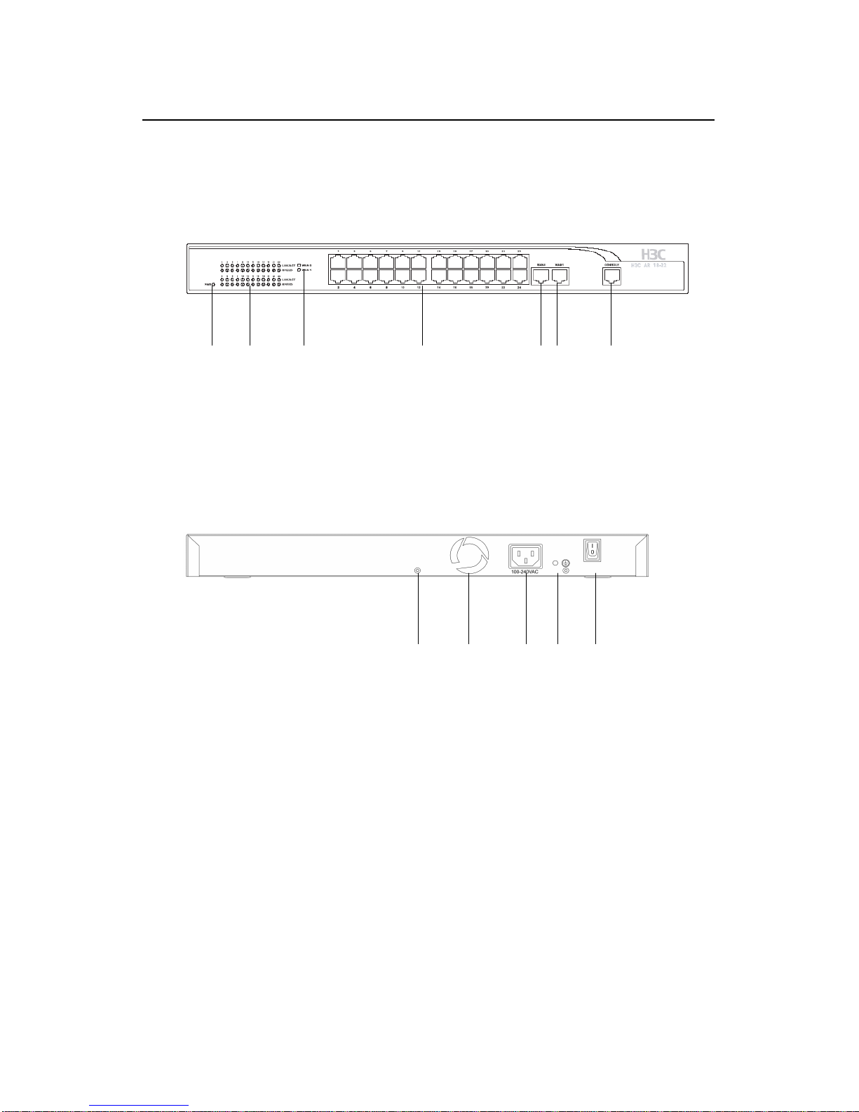
1.2 Product Specifications
I. Panel
(1) (2) (3) (4) (5)(6)
(1) Power LED (PWR) (2) LAN LEDs (LAN1~LAN24)
(3) WAN LED (WAN0/WAN1) (4) LAN interfaces (LAN1~LAN24)
(5) WAN interface (WAN0) (6) WAN interface (WAN1)
(7) Console port (CONSOLE)
Figure 1-1 AR 18-22-24 front panel
(1) (2) (3) (4) (5)(1) (2) (3) (4) (5)
(1) Screw hole (2) Air exhaust
(3) Power socket (4) Grounding screw
(5) Power switch
Figure 1-2 AR 18-22-24 rear panel
Page 5

Installation Manual
H3C AR 18-22-24 Router
Chapter 1
Product Overview
1-3
II. Technical specifications
Table 1-1 Technical specifications of AR 18-22-24
Item Description
Interface
One console port
Two 10/100 Mbps WAN interfaces
24 × 10/100 Mbps LAN interfaces
Flash 8 MB
SDRAM 64 MB
Dimensions (H × W × D) 42 × 435 × 205 mm (1.7 × 17.1 × 8.1 in.)
Weight 3.0 kg (6.6 lb)
Power supply
Rated voltage range: 100VAC to
240VAC, 50 or 60 Hz
Maximum tolerance: 90VAC to
264VAC, 50 or 60 Hz
Power consumption 30W
Operating temperature
0°C to 40°C (32°F to 104°F)
Operating humidity
(noncondensing)
10% to 90%
III. LEDs
AR18-22-24 provides 51 LEDs on its front panel. See the
following table for details.
Page 6

Installation Manual
H3C AR 18-22-24 Router
Chapter 1
Product Overview
1-4
Table 1-2 LEDs on AR 18-22-24
LED Status Description
OFF No link is present.
ON A link is present.
Link/Act
Blinking
Packets are transmitted or
received on the interface.
OFF
The link is in 10 Mbps
mode.
LAN1~LAN24
SPEED
ON
The link is in 10 Mbps
mode.
OFF The router is powered off.
PWR
ON The router is powered on.
OFF No link is present.
ON A link is present.
WAN0/WAN1
Blinking
Packets are transmitted or
received on the interface.
IV. Interface attributes
AR 18-22-24 provides 24 × 10/100 Mbps LAN interfaces, two
10/100 Mbps WAN interfaces and one console port.
1) Console port
Table 1-3 Attributes of the console port
Attribute Description
Connector RJ-45
Page 7

Installation Manual
H3C AR 18-22-24 Router
Chapter 1
Product Overview
1-5
Attribute Description
Interface
standard
Asynchronous RS-232
Baudrate 9600 bps (default) to 115200bps
Function
Connecting an ASCII terminal
Connecting the serial port on a local PC and
running emulation program on the PC
As command line interface (CLI)
2) Ethernet interfaces
Table 1-4 Attributes of Ethernet interfaces
Attribute
10/100BASE-Tx WAN
interface
10/100BASE-Tx LAN
interface
Connector RJ-45
Interface type MDI/MDIX auto-sensing
Operating
mode
10/100 Mbps
auto-negotiation
Full/half duplex
10/100 Mbps
auto-negotiation
Full/half duplex
Only Layer 2 switching
supported
Page 8
Installation Manual
H3C AR 18-22-24 Router
Chapter 2
Product Installation
2-1
Chapter 2 Product Installation
2.1 Installation Requirements
Caution:
To avoid possible product damage or body injury, consider the
following issues.
z Maintain an indoor temperature of 0°C to 40°C (32°F to
104°F) and a humidity level of 10% to 90%.
z Keep the router far away from radio transmitting stations,
radar stations, and high-frequency devices. Use
electromagnetic shielding if necessa ry.
z Do not place the router on an unstable table or platform.
z Make sure that the rack/workbench has a good ventilation
system and is properly grounded.
z Wear an ESD-preventive wrist strap during installation,
making sure that it has good skin contact.
z Reserve adequate clearance at the air inlet and exhaust
ports for proper ventilation.
z For power supply, use a single-phase three-prong power
socket with an earth contact or use a universal PC power
socket, making sure that the earth contact is well connected
to the building ground.
Page 9

Installation Manual
H3C AR 18-22-24 Router
Chapter 2
Product Installation
2-2
z Make sure the correct voltage is used.
z Put a lightning arrester at the front end of the power input to
enhance its lightning protection. To this end, put a special
lightning arrester at the front end of signal cables that are led
outdoors.
z Do not open the chassis when the router is operating or
when electricity hazards are present to avoid electrical
shocks. Before you open the chassis, obtain the permission
of your sales agent.
z Correctly connect the interface cables.
z Do not hot swap any cable.
2.2 Installing the Router
You can place your router on a sturdy tabletop or workbench, or
mount it in a rack.
2.2.1 Placing the Router on a Tabletop/Workbench
When placing the router on a tabletop or wo rkbench,
z Make sure that the tabletop or workbench is sturdy enough.
z Allow 10 cm (3.9 in.) of clearance around the chassis.
z Do not place a router on another.
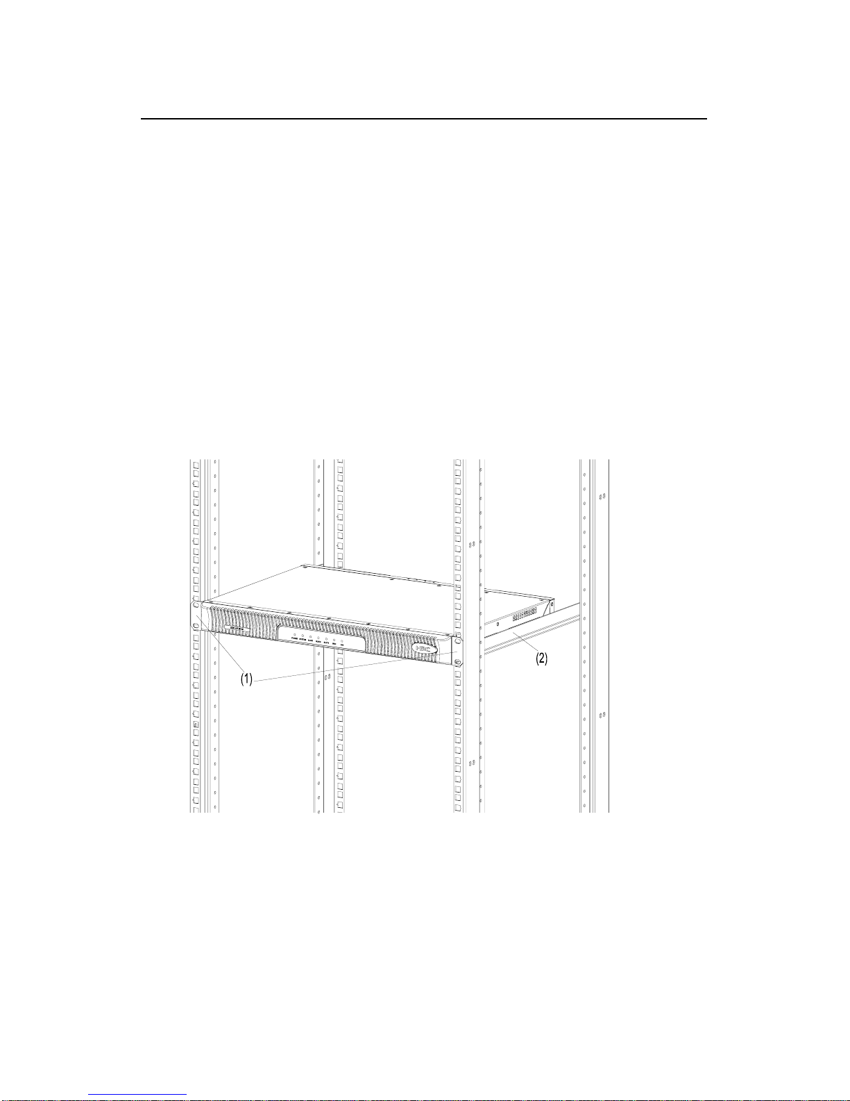
2.2.2 Rack-Mounting the Router
AR 18-22-24 is designed according to the dimensions of the
standard 19-inch cabinet and can be installed in the rack.
Follow these steps to instal l the router (see
Figure 2-1):
Page 10
Installation Manual
H3C AR 18-22-24 Router
Chapter 2
Product Installation
2-3
Step 1: Check the grounding and stability of the rack. Use the
screws to fix the mounting ears at both sides near the front panel or
the rear panel of the router.
Step 2: Put the router in a rack tray. Depending on the actual
situation, slide the router along the chassis guides to an appropriate
place.
Step 3: Fasten the mounting ears with the recess screws to
secure the router in the rack horizontally and firmly. The specifications
of recess screws should satisfy the installation requirements and the
surface of the screws should be anti-rust.
(1) Mounting ear (2) Guide rail
Figure 2-1 Rack-mount AR 18-22-24
Page 11

Installation Manual
H3C AR 18-22-24 Router
Chapter 2
Product Installation
2-4
2.3 Connecting the Ground Wire
Caution:
Properly connect the ground wire before connecting other cables and
shorten it as much as possible to prevent the router and the connected
device from getting damaged during periods of lightning activities.
The grounding screw of the chassis is located on the rear panel.
Connect this screw to the earth ground with a ground wire. The
grounding resistance must not be greater than 5 ohm.
2.4 Connecting the Power Cord
I. AC-input power supply
The required AC input voltage ra nge: 100 VAC to 240 VAC, 50/60
Hz.
The AC-input power socket is illustrated in the following figure.
Page 12

Installation Manual
Chapter 2
Product Installation
H3C AR 18-22-24 Router
2-5
(1)
~
(2)
(1) AC-input power socket (2) Power switch
Figure 2-2 AC-input power socket of AR 18-22-24
II. Recommended AC-input power socket
You are recommended to use a single-phase three-prong socket
with an earth contact, which must be properly grounded. The ground
of the building power system is often buried during the wiring
engineering. Make sure that the building ground is OK before
connecting the AC power cord.
III. Connecting the AC-input power cord
Step 1: Make sure that the grounding screw of the router has
been connected to the earth ground.
Step 2: Put the power switch of the router in OFF position.
Connect the output of the power supply to the power input on the rear
panel of the router, and then insert the input connector of the power
supply into an AC power outlet.
St ep 3: Put the power switch of the router in ON position.
Step 4: Check that the Power LED on the front panel is ON. ON
means the power cord is connected correctly.
Page 13
Installation Manual
H3C AR 18-22-24 Router
Chapter 2
Product Installation
2-6
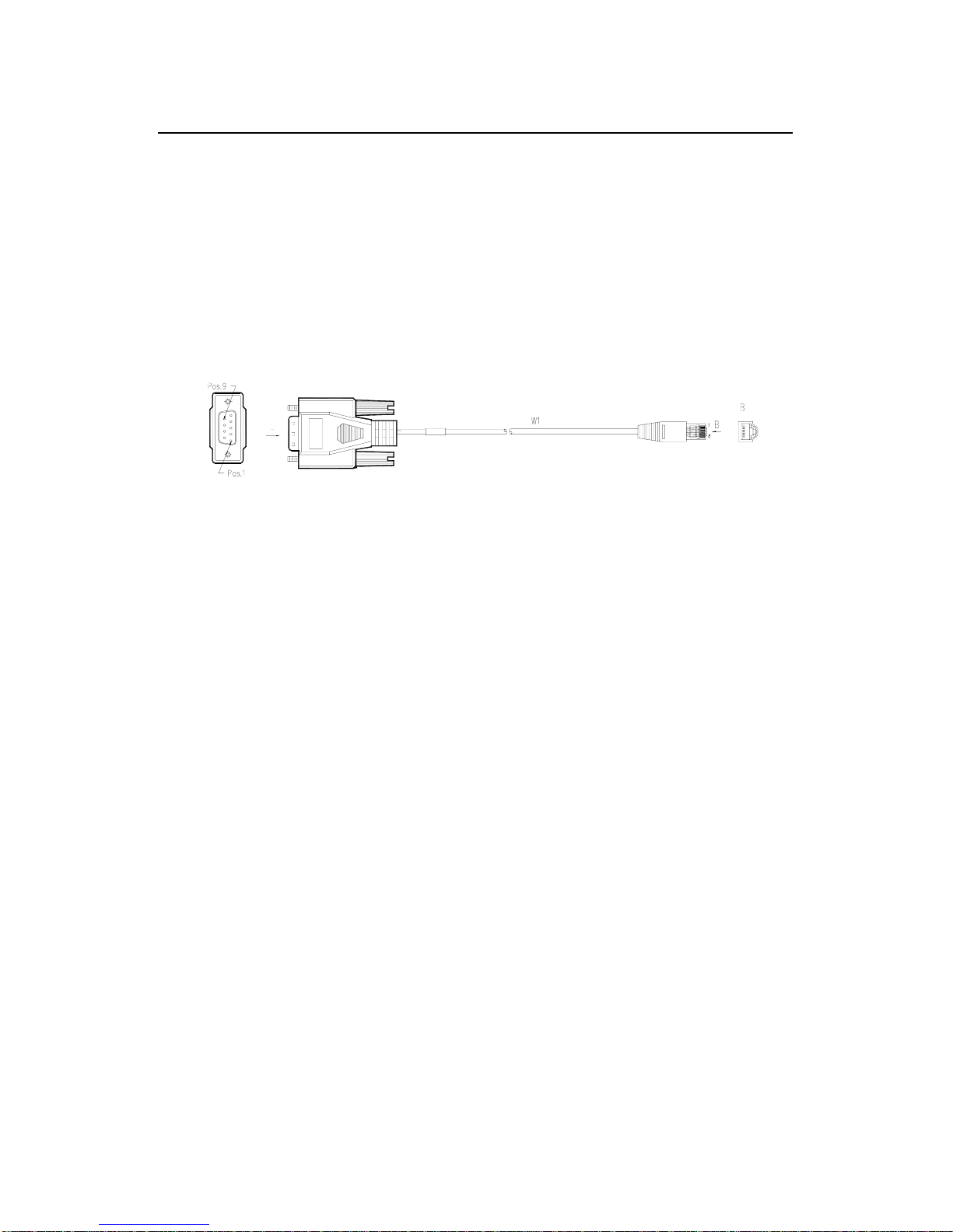
2.5 Connecting the Router to a Console
Terminal
I. Console cable
The console cable has an RJ-45 connector at one end and a DB9
(female) connector at the other end.
A
A
Figure 2-3 Console cable assembly
II. Connecting the console cable
Follow these steps to connect the router to a console terminal:
St ep 1: Select a console terminal.
The console terminal can be either a standard ASCII terminal
with an RS-232 serial interface or more commonly, a PC.
Step 2: Connect the console cable.
Power off the router and the console terminal, and then connect
the RS-232 serial port on the console terminal to the console port on
the router using the console cable.
V erify the connection and powe r on the router. If everything is OK,
the startup information is displayed on th e terminal screen. For details,
refer to
3.1.2 Powering On the Router.
Page 14

Installation Manual
H3C AR 18-22-24 Router
Chapter 2
Product Installation
2-7
2.6 Connecting the Router to LAN
I. Ethernet cable
A 10/100Base-TX Ethernet interface is usually connected to an
Ethernet using a category 5 twisted pair cable as shown in following
figure.
Figure 2-4 Ethernet cable assembly
Ethernet cables fit into two categories: straight-through and
crossover.
z Straight-through cable: The wires at both ends are crimped
in the same sequence in the RJ-45 connectors. The cable is
used for connecting different types of devices, such as a
terminal device (PC for example) or router to a Hub or LAN
switch.
z Crossover cable: The wires at both ends are crimped in
different sequence in the RJ-45 connectors. The cable is
used for connecting the same type of devices, su ch as a PC
to another PC or to a router.
Page 15

Installation Manual
H3C AR 18-22-24 Router
Chapter 2
Product Installation
2-8
Caution:
In preparing network cables, shielded cables are preferred for the
sake of electromagnetic compatibility.
II. Connecting the Ethernet cable
Caution:
Observe carefully the mark above the port before making connection
to make sure it is the right port.
The 10/100BASE-Tx interfaces on AR 18-22-24 support
auto-MDI/MDIX, so you can use either the straight-through cable or
crossover cable to connect a PC, router, HUB or LAN switch.
z Connect the cable to the Ethernet port on the router;
z Connect the other end of the cable to the peer device.
Page 16

Installation Manual
H3C AR 18-22-24 Router
Chapter 2
Product Installation
2-9
2.7 Verifying Installation
After you complete installation, verify that:
z The required power supply is used.
z The ground wire of the router is correctly connected.
z The console cable and the power cord are correctly
connected.
Page 17

Installation Manual
H3C AR 18-22-24 Router
Chapter 3 Configuring and
Maintaining the Route
r
3-1
Chapter 3 Configuring and Maintaining
the Router
3.1 Configuring the Router
3.1.1 Setting up Configuration Environment
I. Connecting a console terminal to the router
Connect the RJ-45 connector of the console cable to the console
port on the router, and the DB9 connector to the serial port on the
console terminal (a PC for example), as shown in
Figure 3-1.
PC
Router
Console cable
To console
port
t
Figure 3-1 Local configuration through the console por
II. Setting up the console terminal
Step 1: Start the console terminal and create a new connection.
Run on the terminal the emulation (the Terminal on Windows3.1,
the HyperTerminal on Windows95/Windows98/Windows NT for
example) and create a new connection. Enter the name of the new
connection in the Name field and click <OK>. See
Figure 3-2.
Page 18

Installation Manual Chapter 3 Configuring and
Maintaining the Route
r
H3C AR 18-22-24 Router
3-2
Figure 3-2 Create a new connection
Step 2: Define terminal parameters (using the HyperTerminal on
Windows98 as an example).
1) Select the serial port to be used from the Connect using
drop-down list. The serial port must be the port physically
connected with the console cable.
Page 19

Installation Manual Chapter 3 Configuring and
Maintaining the Route
r
H3C AR 18-22-24 Router
3-3
Figure 3-3 Choose connection port
2) Define port parameter.
In the page as shown in
Figure 3-4, make these settings:
z Bits per second: 9600
z Data bits: 8
z Parity: None
z Stop bits: 1
z Flow control: None.
Click <OK> to return to the HyperTerminal window.
Page 20

Installation Manual Chapter 3 Configuring and
Maintaining the Route
r
H3C AR 18-22-24 Router
3-4
Figure 3-4 Define port parameters
3) Set emulation type.
Choose [Properties/Settings] to enter the corresponding page
and select the emulation as VT100 or Auto detect. Click <OK> to
return to the HyperTerminal window.
Page 21

Installation Manual Chapter 3 Configuring and
Maintaining the Route
r
H3C AR 18-22-24 Router
3-5
Figure 3-5 Set emulation type
3.1.2 Powering On the Router
After the router is powered on, the Boot Rom program runs first
and the following system information appears on the terminal screen:
Router starts booting... (V2.00)
Starting at 0x1500000...
********************************************
* *
Page 22

Installation Manual
H3C AR 18-22-24 Router
Chapter 3 Configuring and
Maintaining the Route
r
3-6
* H3C Series Routers Boot Rom, V9.00 *
* *
********************************************
Compiled at 18:00:31 , Jan 18 2005.
Testing memory...OK!
64M bytes SDRAM
8192k bytes flash memory
Hardware Version is MTR 2.0
CPLD Version is CPLD 1.0
Press Ctrl-B to enter Boot Menu
System is self-decompressing.........................
....................OK!
System is starting...
Starting at 0x10000...
Press <Enter> and the screen displays (providing that no login
authentication is set):
<H3C>
Now the router has entered the user view and is ready for your
configuration.
3.2 Maintaining the Router
3.2.1 Boot Menu
Start the router. When the prompt “Press Ctrl-B to enter Boot
Menu” appears on the terminal screen, press <Ctrl+B>. The system
displays:
Please input Boot Rom password :
Page 23

Installation Manual
H3C AR 18-22-24 Router
Chapter 3 Configuring and
Maintaining the Route
r
3-7
Caution:
z To enter the Boot Menu, you mu st press <Ctrl+B> within three
seconds after the prompt “Press Ctrl-B to Enter Boot Menu...”
appears. Otherwise, the system starts decompressing the
program.
z If you want to enter the Boot menu after the system starts
decompressing the program, you need to reboot the router.
Type the correct password and press <Enter>. (If no Boot Rom
password is configured, just press <Ente r>.) The system accesses the
Boot menu as follows:
Boot Menu:
1: Download application program with XMODEM
2: Download application program with NET
3: Start up and ignore configuration
4: Enter debugging environment
5: Boot Rom Operation Menu
6: Do not check the version of the software
7: Exit and reboot
Enter your choice(1-7):
1) Refer to 3.2.2 for details about “Download application
program with XModem”.
2) If selecting the “Download application program with NET”
option, you can enter the Net port download menu as
follows:
Net Port Download Menu:
Page 24

Installation Manual
H3C AR 18-22-24 Router
Chapter 3 Configuring and
Maintaining the Route
r
3-8
1: Change Net Parameter
2: Download From Net
3: Exit to Main Menu
Enter your choice(1-3):1
z Change Net Parameter
The following information is prompted for this option:
Change Boot Parameter:
'.' = clear field; '-' = go to previous field; ^D = quit
boot device : fei0
processor number : 0
host name : 8040
file name : M8240ram.arj
inet on ethernet (e) : 169.254.10.10
inet on backplane (b):
host inet (h) : 169.254.10.11
gateway inet (g) :
user (u) : 8040
ftp password (pw) (blank = use rsh):
flags (f) : 0x0
target name (tn) :
startup script (s) :
other (o) :
Note:
You just enter the new parameters after colons.
Page 25

Installation Manual
H3C AR 18-22-24 Router
Chapter 3 Configuring and
Maintaining the Route
r
3-9
AR 18-22-24 support application program upgrade using TFTP or
FTP. Refer to
3.2.5 Upgrading the Application Program through
Networks
for details.
z Download from Net
You can choose this option to begin the download after desired
parameters are defined.
Caution:
Care should be taken in deciding to upgrade router softwa re. Upgrade
the software of your AR 18-22-24 with the assistance of technicians
and when absolutely needed. Make sure the version of the Boot Rom
matches that of the application.
3) When selecting the “Boot Rom Operation Menu” option, the
screen displays:
Boot Rom Download Menu:
1: Download Boot ROM with XModem
2: Download Extended Segment of Boot Rom with XModem
3: Restore Extended Segment of Boot Rom from FLASH
4: Backup Extended Segment of Boot Rom to FLASH
5: Exit to Main Menu
Enter your choice(1-5):
The menu provides means to upgrade, back up and restore the
Boot Rom program. Refer
3.2.2 and 3.2.3 for details.
Page 26

Installation Manual
H3C AR 18-22-24 Router
Chapter 3 Configuring and
Maintaining the Route
r
3-10
4) The “Do not check the version of the software” option is used
for backward compatibility purpose during upgrade. Your
upgrade attempt may fail even if you select the correct
software version (the system prompts you with “invalid
version” message at this time). If you are experiencing this,
you can select this option to have the system skip version
check during upgrade. This option, however, works only
once; the system checks software version all the same at
reboot.
3.2.2 Upgrading Software through XModem
When upgrading software through XModem, you can simply use
the console port without building up another configuration
environment.
I. Upgrading the application program
S tep 1: Enter Boot menu a nd p ress <1 >. The follo win g downl oad
speeds are available with the router:
Downloading application program from serial ...
Please choose your download speed:
1: 9600 bps
2: 19200 bps
3: 38400 bps
4: 57600 bps
5: 115200 bps
6: Exit and reboot
Enter your choice(1-6):
Step 2: Select an appropriate download speed, <5> for 115200
bps for example. The cons ole screen displays:
Page 27

Installation Manual
H3C AR 18-22-24 Router
Chapter 3 Configuring and
Maintaining the Route
r
3-11
Download speed is 115200 bps. Change the terminal's speed
to 115200 bps, and select XModem protocol. Press ENTER key
when ready.
Step 3: Change the baud rate on the console terminal to a value
identical to the software download speed (115200 bps in this example).
After that, select [Dial-in/Disconnect] and then [Dial-in/Dialing] to
disconnect and reconnect the terminal. Press <Enter> to start
downloading. During course of downloading, the console screen
displays:
Downloading ... CCCCC
Note:
To validate the new baud rate setting on the console terminal, you
must disconnect and then reconnect the terminal emulation program.
Step 4: Select [Transfer/Send file…] in the HyperTerminal. The
Send File dialog box appears, as shown in
Figure 3-6.
Figure 3-6 Send File dialog box
Page 28

Installation Manual
H3C AR 18-22-24 Router
Chapter 3 Configuring and
Maintaining the Route
r
3-12
Step 5: In the Send File dialog box, click <Browse…> and
navigate to the directory where the desired file resides to select the
application file to be downloaded, and then select XModem from the
Protocol drop-down list. Then click <Send>. The following interface
pops up:
Figure 3-7 Sending file interface
Step 6: After completing the downloading, the system begins
writing to Flash memory. You will be prompted with the following
message when the writing process finishes:
Download completed.
Writing to flash memory...
Please wait,it needs a long time .Please wait...
#######################################################
Writing FLASH Success.
Page 29

Installation Manual
H3C AR 18-22-24 Router
Chapter 3 Configuring and
Maintaining the Route
r
3-13
Please use 9600 bps.Press <ENTER> key to reboot the
system.
Restore the speed of the console terminal to 9600 bps as
prompted, disconnect and reconnect the terminal. The system starts
up normally.
II. Upgrading the Boot Rom program
Step 1: Enter the Boot menu, and then select <5> to enter the
Boot Rom download menu.
Step 2: Select <1> in the menu to download the Boot Rom
program through XModem. The subsequent steps are the same as
those described in the Upgrading the application program section.
Caution:
Failures during upgrading the entire Boot Rom cannot be recovered
on-site, so upgrade the entire Boot Rom with the assistance of a
technician when absolutely needed.
III. Upgrading the extended segment of the Boot Rom
program
Step 1: Enter the Boot menu, and then select <5> to enter the
Boot Rom download menu.
Step 2: Select <2> in Boot Rom download menu to download
extended segment of Boot Rom with XModem. The subsequent step s
Page 30

Installation Manual
H3C AR 18-22-24 Router
Chapter 3 Configuring and
Maintaining the Route
r
3-14
are the same as those described in the Upgrading the application
program section.
Caution:
This approach upgrades only a portion of the Boot Rom program, so
you can make a second attempt once errors occur.
3.2.3 Backing Up and Restoring the Extended
Segment of the Boot Rom Program
I. Backing up the extended segment to Flash memory
Follow these steps to back up the extended segment of the Boot
Rom program:
Step 1: Enter the Boot menu, and then select <5> to enter the
Boot Rom download menu.
Step 2: Select <4> in Boot Rom download menu to back up the
extended segment of the Boot Rom program in use to Flash memory.
For a successful backup, the console screen displays:
Writing to FLASH.Please wait...####
Backuping Boot Rom program to FLASH successed!
Step 3: When Boot Rom download menu appears again, select
<5> to exit and reboot the router.
Page 31

Installation Manual
H3C AR 18-22-24 Router
Chapter 3 Configuring and
Maintaining the Route
r
3-15
II. Restoring the extended segment from Flash memory
In case faults occur to the extended segment or the upgrade is
done inadvertent, take these step s to restore the extended segment of
the Boot Rom program from Flash memory to the Boot Rom:
Step 1: Enter the Boot menu, and then select <5> to enter the
Boot Rom download menu.
Step 2: In Boot Rom download menu, select <3> to restore the
extended segment from Flash memory.
For a successful restoration, the console screen displays:
Writing to Boot Rom.Please wait...######
Restoring Boot Rom program successed!
Step 3: When Boot Rom download menu appears again, select
<5> to exit and reboot the router.
3.2.4 Upgrading Boot ROM at CLI
After the router starts normally, you can upgrade and back up
application programs, and backup and restore the configuration at the
command line interface (CLI)
I. Upgrading Boot ROM Through TFTP
1) Connect the TFTP server to the router on which Boot ROM
is to be upgraded so that they can communicate with each
other. A TFTP server is a device running the TFTP server
program.
2) Specify the path on the TFTP server to the folder that
contains the Boot ROM upgrade file. That is, ensure the
Boot ROM upgrade file are available in the Base Directory
Page 32

Installation Manual
H3C AR 18-22-24 Router
Chapter 3 Configuring and
Maintaining the Route
r
3-16
folder, as shown in Figure 3-8 (For different TFTP server
software packages, the interfaces differ).
Figure 3-8 TFTP server program interface
3) Configure the router to download the Boot ROM upgrade file
from the TFTP server.
<H3C> tftp 1.1.1.1 get bootromfull
As shown in the above display, 1.1.1.1 is the IP address of the
TFTP server, and bootromfull is the Boot ROM upgrade file.
4) Execute the following command on the router to upgrade
Boot ROM.
<H3C> system-view
[H3C] upgrade bootrom full
Page 33

Installation Manual
H3C AR 18-22-24 Router
Chapter 3 Configuring and
Maintaining the Route
r
3-17
WARNING: This operation will update the Boot ROM.
It may result in booting failure.
Caution!!! upgrade bootrom [Y/N]?y
Please wait, it may take a long time
The upgrade succeeds!
5) After the upgrade operation is complete, restart the router so
that the upgrade made to the Boot ROM takes effect. After
the router is restarted, you can use the display version
command to display the current Boot ROM version, or
directly enter the Boot ROM menu, so as to verify the
upgrade operation.
II. Upgrading Boot ROM Through FTP
1) Connect the FTP server to the router on which Boot ROM is
to be upgraded so that they can communicate with each
other. An FTP server is a device running the FTP server
program.
2) Specify the path on the FTP server to the folder that contains
the Boot ROM upgrade file, and set the username and
password. As shown in
Figure 3-9, configure the username
in the Profile text box and set a password. Make sure the
currently configured path contains the Boot ROM upgrade
file. (For different FTP server software packages, the
interfaces differ).
Page 34

Installation Manual Chapter 3 Configuring and
Maintaining the Route
r
H3C AR 18-22-24 Router
3-18
Figure 3-9 FTP server program interface
3) Configure the router to download the Boot ROM upgrade file
from the FTP server.
<H3C> ftp 1.1.1.1
Trying 1.1.1.1 ...
Press CTRL+K to abort
Connected to 1.1.1.1.
220 3Com 3CDaemon FTP Server Version 2.0
User(1.1.1.1:(none)):guest //Enter the username
configured on the FTP server.
331 User name ok, need password
Password: // Enter the corresponding
password.
230 User logged in//The connection is established
successfully.
[ftp] get bootromfull
Page 35

Installation Manual
H3C AR 18-22-24 Router
Chapter 3 Configuring and
Maintaining the Route
r
3-19
4) Execute the following command on the router to upgrade
Boot ROM.
<H3C> system-view
[H3C] upgrade bootrom full
WARNING: This operation will update the Boot ROM.
It may result in booting failure.
Caution!!! upgrade bootrom [Y/N]?y
Please wait, it may take a long time
The upgrade succeeds!
5) After the upgrade operation is complete, restart the router so
that the upgrade made to the Boot ROM takes effect. After
the router is restarted, you can use the display version
command to display the current Boot ROM version, or
directly enter the Boot ROM menu, so as to verify the
upgrade operation.
3.2.5 Upgrading the Application Program through
Networks
When downloading applications through networks, the router
operates as a client and you need to connect to a TFTP server o r FTP
server through one of its fixed Ethernet interfaces.
Page 36

Installation Manual
H3C AR 18-22-24 Router
Chapter 3 Configuring and
Maintaining the Route
r
3-20
Caution:
z TFTP server or FTP server is not shipped with your AR18-22-24,
you need to purchase and install it by yourself.
z On AR 18-22 -24 you can only upgrade the application program
through the WAN0 interface.
Follow these steps to upgrade the application program through
networks:
1) Start TFTP server or FTP server.
Start TFTP server or FTP server on the PC connected to the
Ethernet interface on the router and set the path for getting the source
file. User name and password are required for the FTP server.
2) Enter the Net port download menu.
In Boot menu, select <3> to enter Net port download menu.
3) Enter the Change Download Parameter page.
In Net port download menu, select <1> to change the download
parameters.
z In TFTP mode, you need to configure these parameters:
file name: Name of the file to be loaded.
inet on ethernet (e): IP address of the download interface on the
router.
host inet (h): IP address of the TFTP server.
flags (f): You must enter 0x80 for TFTP mode.
Page 37

Installation Manual
H3C AR 18-22-24 Router
Chapter 3 Configuring and
Maintaining the Route
r
3-21
z In FTP mode, you need to configure these parameters:
file name: Name of the file to be loaded.
inet on ethernet (e): IP address of the download interface on the
router.
host inet (h): IP address of the FTP server.
user (u): User name, which must be consistent with that on the
FTP server.
ftp password (pw) (blank = use rsh): Password, which must be
consistent with that on the FTP server.
flags (f): You must enter 0x0 for FTP mode.
After you configure these parameters, the system saves them
automatically.
4) The upgrading succeeds and the router reb oots.
Press <Enter> and the system returns to Net port download
menu. Select <2> and the system displays:
boot device : fei
unit number : 0
processor number : 0
host name : 8040
file name : Q8040.BIN
inet on ethernet (e) : 10.110.27.235
host inet (h) : 10.110.27.231
user (u) : 8040
ftp password (pw) : 8040
flags (f) : 0x80
Attached TCP/IP interface to fei0.
Subnet Mask: 0xfffff800
Page 38

Installation Manual
H3C AR 18-22-24 Router
Chapter 3 Configuring and
Maintaining the Route
r
3-22
Attaching network interface lo0... done.
Loading...
NET download completed...
read len = [04378489]
Please wait,it needs a long time
#######################################################
###########################
Writing Comwaresoftware File Succeeds!
Press <Enter> key to reboot the system .
Then the upgrade succeeds. Press <Enter> and the router
reboots.
Page 39

Installation Manual
H3C AR 18-22-24 Router
Chapter 4 Installation
Troubleshooting
4-1
Chapter 4 Installation Troubleshooting
4.1 Troubleshooting the Power Supply
1) Symptom
The Power LED is OFF.
2) Solution
Please check
z If the router power switch is turned on.
z If the site power supply is turned on.
z If the power cord is properly connected.
z If the required power supply is used.
Caution:
Never hot swap the power cord. If the Power LED remains OFF after
these checkups, please contact the agent.
4.2 Troubleshooting the Console Terminal
If everything is OK, the console terminal shall display booting
information on the screen after the router is powered on. Otherwise,
the console terminal may display nothing or illegible characters.
Page 40

Installation Manual
H3C AR 18-22-24 Router
Chapter 4 Installation
Troubleshooting
4-2
I. No display on the terminal screen
1) Symptom
The console terminal displays nothing on the screen after the
router is powered on.
2) Solution
S t ep 1: Please check
z If the power supply is OK.
z If the console cable is properly connected.
Step 2: If no problem is found in the checkups, examine the
console cable itself and parameters settings of the terminal (such as
HyperTerminal).
II. Illegible characters on the terminal screen
1) Symptom
The console terminal displays illegible characters on the screen
after the router is powered on.
2) Solution
Check parameters settings for the terminal (such as
HyperTerminal):
z Bits per second: 9600
z data bits: 8
z Parity: none
z Stop bit: 1
z Flow control: None
z Emulation: VT100 or auto-detect.
If they are not set to these values, modify them.
Page 41

Installation Manual
H3C AR 18-22-24 Router
Chapter 4 Installation
Troubleshooting
4-3
4.3 Handling Lost Boot Rom Password
Please contact the local Huawei-3Com agent if your Boot Rom
password of the router is lost. Then you can get assistance to enter
the router again and set a new password.
 Loading...