

Page 1

© 2017 erie water treatment TM-EN-H2O-CS-ECO-Rev2017.03
Technical Manual
WATER SOFTENER
Models: H2O-CS-ECO
Page 2

TABLE OF CONTENT
Page 2
Table of content ...................................................................................................................Page 2
Warning & Safety instructions ..............................................................................................Page 3
Operating conditions & Requirements .................................................................................Page 4
Installation ...........................................................................................................................Page 5
Commissioning .....................................................................................................................Page 6
Electronic control panel .......................................................................................................Page 7
Maintenance ........................................................................................................................Page 11
Hydraulic flow diagram ........................................................................................................Page 12
Troubleshooting ...................................................................................................................Page 14
Electrical wiring diagram ......................................................................................................Page 16
Default configuration parameter settings.............................................................................Page 17
Exploded view - System .......................................................................................................Page 18
Exploded view - Valve body assembly ..................................................................................Page 20
Exploded view - Valve head & Timer assembly .....................................................................Page 22
Technical data ......................................................................................................................Page 23
Page 3

WARNING & SAFETY INSTRUCTIONS
Page 3
Before you begin the installation of the appliance, we advise you read
and carefully follow the instructions contained in this manual. It contains
important information about safety, installation, use and maintenance of
the product. The actual system that you have received, may differ from
the pictures/illustrations/descriptions in this Technical Manual.
Failure to follow the instructions could cause personal injury or damage
to the appliance or property. Only when installed, commissioned and
serviced correctly, the appliance will offer you many years of trouble-free
operation.
The appliance is intended to 'soften' the water, meaning it will remove
hardness minerals; it will not necessarily remove other contaminants
present in the water. The appliance will not purify polluted water or make
it safe to drink!
Installation of the appliance should only be undertaken by a competent
person, aware of the local codes in force. All plumbing and electrical
connections must be done in accordance with local codes.
Before setting up the appliance, make sure to check it for any externally
visible damage; do not install or use when damaged.
Use a hand truck to transport the appliance. To prevent accident or
injury, do not hoist the appliance over your shoulder. Do not lay the
appliance on its side.
Keep this Technical Manual in a safe place and ensure that new users are
familiar with the content.
The appliance is designed and manufactured in accordance with current
safety requirements and regulations. Incorrect repairs can result in
unforeseen danger for the user, for which the manufacturer cannot be
held responsible. Therefore repairs should only be undertaken by a
competent technician, familiar and trained for this product.
In respect of the environment, this appliance should be disposed of in
accordance with Waste Electrical and Electronic Equipment
requirements. Refer to national/local laws and codes for correct recycling
of the appliance.
Page 4

OPERATING CONDITIONS & REQUIREMENTS
Page 4
OPERATING PRESSURE MIN-MAX: 1,4-5,0 bar / 20-73 psi
for cold water applications (max. 48 °C (120 °F)) max. operating
pressure is 8,3 bar (120 psi).
this appliance is configured to perform optimally at an
operating pressure of 3 bar (45 psi) ±½ bar (7 psi); in case of a
lower or higher operating pressure the performance may be
affected negatively!
check water pressure regularly.
take into account that night time water pressure may be
considerably higher than day time water pressure.
install a pressure reducer ahead of the appliance if necessary.
OPERATING TEMPERATURE MIN-MAX: 2-65 °C / 35-149 °F
do not install the appliance in an environment where high
ambient temperatures (e.g. unvented boiler house) or freezing
temperatures can occur.
the appliance cannot be exposed to outdoor elements, such as
direct sunlight or atmospheric precipitation.
ELECTRICAL CONNECTION:
the appliance only works on 24 VAC; always use it in
combination with the supplied transformer.
make sure to plug the transformer into a power outlet, which is
installed in a dry location, with the proper rating and overcurrent protection.
Page 5
INSTALLATION
Page 5
PREPARATION BRINE CABINET
Picture 1&11
To facilitate the installation, you may want to remove the salt
lid and main cover from the brine cabinet.
1. Remove the salt lid.
2. Unscrew the screw rivets at the front of the main cover.
3. Carefully lift the main cover from the water softener.
CASTER WHEELS (optional on micro & mini only)
In case the water softener is delivered with the optional
caster wheel set, it needs to be mounted on the cabinet upon
installation of the water softener.
Picture 2
1. Position the reinforcement plate on the bottom of the
water softeners cabinet, making sure the 4 holes in the
reinforcement plate align properly with the 4 threaded
sockets in the cabinet.
2. Screw the 4 caster wheels into the threaded sockets;
make sure to install the washers. Tighten firmly. Make
sure the 2 caster wheels with brake are easily accessible.
INLET & OUTLET
In case of high concentration of impurities in the inlet
water, we recommend the installation of a sediment filter,
ahead of the appliance.
We strongly recommend the use of flexible hoses to
connect the appliance to the water distribution system; use
hoses with a large diameter in order to limit the pressure
loss.
The inlet/outlet adaptors are equipped with an
integrated non-return valve, to prevent any kind of backflow
into the water softener or mains water supply; make sure to
install them in the correct flow direction!
If the appliance is not equipped with the factory bypass
(optional), we strongly recommend to install a 3-valve
bypass system (not included with this product!) to isolate the
appliance from the water distribution system in case of
repairs. It allows to turn off the water to the appliance, while
maintaining (untreated) water supply to the user.
WITH FACTORY BYPASS (optional)
Picture 3
= mains water supply (untreated water)
= inlet of appliance (untreated water)
= outlet of appliance (treated water)
= application (treated water)
1. Screw the factory bypass onto the elbow connections of
the appliance (&); make sure to install the gasket
seals. Tighten the nuts firmly by hand.
2. Screw the connection kit with nuts onto the factory
bypass (&); make sure to install the gasket seals.
Tighten the nuts firmly by hand.
3. Connect the mains water supply to the adaptor on the
inlet port of the factory bypass ().
4. Connect the application to the adaptor on the outlet port
of the factory bypass ().
WITH 3-VALVE BYPASS SYSTEM (not included)
Picture 4
= inlet of appliance (untreated water)
= outlet of appliance (treated water)
1. Install the 3-valve bypass system.
2. Screw the connection kit with nuts onto the elbow
connections of the appliance (&); make sure to install
the gasket seals. Tighten the nuts firmly by hand.
3. Connect the 3-valve bypass system to the adaptors on the
in () and out () elbow connections.
4. Connect the mains water supply to the inlet of the 3-valve
bypass system.
5. Connect the application to the outlet of the 3-valve
bypass system.
DRAIN
We recommend the use of a stand pipe with P-trap.
To prevent backflow from the sewerage system into the
appliance, always install and use the included drain adaptor
with air gap and double hose barb, to connect the drain
hoses to the sewerage system.
Always use separate drain hoses for the control valve
(discharge of rinse water) and the brine cabinet's overflow.
Lay-out the drain hoses in such a way that pressure loss
is minimized; avoid kinks and unnecessary elevations.
Make sure that the sewerage system is suitable for the
rinse water flow rate of the appliance.
Picture 5
1. Install the drain adaptor to the sewerage system; it fits
over a 32 mm pipe or inside a 40 mm pipe adaptor. Ensure
a permanent and watertight connection.
2. Connect a 13 mm hose to the drain solenoid of the control
valve (); secure it by means of a clamp.
3. Run the drain hose to the drain adaptor and connect it to
one of the hose barbs; secure it by means of a clamp. This
drain line operates under pressure, so it may be installed
higher than the appliance.
4. Connect a 13 mm hose to the brine cabinet overflow
elbow; secure it by means of a clamp.
5. Run the drain hose to the drain adaptor and connect it to
the other hose barb; secure it by means of a clamp. This
drain line does NOT operate under pressure, so it may
NOT be installed higher than the appliance.
Page 6
COMMISSIONING
Page 6
ELECTRICAL
Picture 6
1. Plug the transformers output lead into the socket on the
appliances power cord; secure it by means of the
TwistLock clamp.
2. Plug the transformer into an electrical outlet.
PRESSURIZING
1. Make sure the bypass system is in 'bypass' position.
2. Make sure the electronic controller of the appliance is in
service mode.
3. Open the mains water supply.
4. Open a cold treated water faucet nearby the appliance
and let the water run for a few minutes until all air is
purged and all foreign material that may have resulted
from the installation is washed out; close the tap.
5. Gently pressurize the appliance, by putting it into service:
factory bypass:
1. open the 'outlet' valve;
2. slowly open the 'inlet' valve.
3-valve bypass:
1. close the 'bypass' valve;
2. open the 'outlet' valve;
3. slowly open the 'inlet' valve.
6. After 2-3 minutes, open a cold treated water faucet
nearby the appliance and let the water run for a few
minutes until all air is purged from the installation and the
resin bed is rinsed (it is normal for the rinse water to show
some discoloration!); close the tap.
7. Check the appliance and all hydraulic connections for
leaks.
After the first regenerations of the appliance, some
slight discoloration of the treated water might occur. This is
totally harmless and will disappear rapidly!
BRINE CABINET
1. Add water conditioner salt to the brine cabinet.
ELECTRONIC CONTROL PANEL
1. Program the electronic controller.
ADJUSTMENT RESIDUAL HARDNESS
WITH FACTORY BYPASS (optional)
In practice the residual hardness is influenced by the
inlet pressure, flow rate and hardness of the incoming
untreated water. When adjusting the residual hardness,
make sure these conditions are similar to the actual
operating conditions.
Picture 7
1. Adjust the residual hardness of the water that leaves the
appliance, by means of the adjusting screw, incorporated
in the ‘outlet’ valve of the factory bypass:
to raise the residual hardness: turn the screw counter
clockwise.
to reduce the residual hardness: turn the screw
clockwise.
2. Measure the residual water hardness with a water
hardness test kit; readjust if necessary.
PERFORM REGENERATION
1. Manually initiate a regeneration, by pressing the scroll
button; the display will show:
2. Leave the appliance in this position; the countdown timer
will countdown to 0 sec and start a regeneration.
Regen in 10 sec
Page 7
ELECTRONIC CONTROL PANEL
Page 7
Picture 8
symbol
button
function
SCROLL
to advance to the next
parameter
UP
to
increase the value of the
parameter
DOWN
to decrease the value of the
parameter
POWER-UP
After power-up the display will show the 5-digit Part Number
of the electronic board and the installed software version.
POWER FAILURE
In the event of a power failure, the program will remain
stored in the NOVRAM® during an undefined period, while an
incorporated SuperCap will maintain the correct time of day
during a period of several hours; consequently, in case of
prolonged power failure, the time of day might not be
maintained; if this happens, the time of day will be reset to
8:00 when the power supply is re-established, while the
indication will flash, indicating that the time of day needs to
be set.
When the power failure occurs during the execution of an
automatic regeneration, the appliance will immediately
return to the service mode; when the power supply is reestablished, the appliance will resume the regeneration.
TIMER FAILURE
In the event of a timer failure, the display will show the
message:
If powering off/on the appliance doesn’t solve this problem,
professional service is required.
MAINTENANCE REMINDER
Only available if the maintenance reminder function has
been activated and programmed by your supplier!
Once the maintenance interval is reached, the display will
intermittently show the message:
While the appliance will continue to operate normally, it is
recommended to have preventive maintenance performed
by a professional.
To reset the maintenance reminder, simply access the
configuration parameters programming mode.
SERVICE MODE
In service mode the display shows the time of day and the
remaining capacity:
REGENERATION MODE
In regeneration mode the display shows the actual
regeneration cycle and, where relevant, the total remaining
regeneration time and remaining cycle time:
The appliance can be reset to service mode at any time by
pressing the scroll button, as such manually advancing it
through the regeneration cycles.
CHECKING THE FLOW METER
In case of water usage, the remaining capacity counter in the
service display will count back per unit, i.e. per litre. This way
the correct functioning of the water meter can be verified.
MANUAL REGENERATION
It is possible to manually initiate an immediate regeneration
or a delayed regeneration (at the preprogrammed time of
regeneration).
1. Press the scroll button; the display will show:
If the control panel is left in this position, the
countdown timer will countdown to 0 sec and start an
immediate regeneration.
To cancel this mode, press the scroll button before
the countdown timer has reached 0 sec; the display
will show:
If the control panel is left in this position, a delayed
regeneration will be started at the indicated
preprogrammed time of regeneration.
To cancel this mode, press the scroll button; the
control panel will return to the service mode.
Service Required
BRINE FILL
REGEN PENDING
Rgn:XXX CycY:ZZZ
8:01 1000L -
Regen in 10 sec
Regen @ 2:00
Maintenance Now
Page 8
ELECTRONIC CONTROL PANEL
Page 8
PROGRAMMING INSTRUCTIONS -
BASIC SETTINGS
Before entering the programming mode, make sure that
the appliance is in service mode.
In case no button is pressed in a period of 5 min, the
control panel will automatically return to the service mode;
any changes made will NOT be saved!
1. Press the scroll button and hold it for 2 sec until the
display shows:
Press the up or down button to set the
language.
2. Press the scroll button again; the display will show:
Press the up or down button to set the time of
day.
3. Press the scroll button again; the display will show:
Press the up or down button to set the unit of
measure for water hardness. Make sure it is identical
to the unit of measure of the water hardness test kit
or water analysis report that is used to determine the
hardness of the incoming untreated water!
4. Press the scroll button again; the display will show:
Press the up or down button to set the hardness
of the incoming untreated water.
5. Press the scroll button again; the display will show:
Press the up or down button to save the settings
into the NOVRAM® and exit the programming mode.
PROGRAMMING INSTRUCTIONS -
CONFIGURATION PARAMETERS
All configuration parameters on this appliance have
been pre-programmed in the factory, to offer optimal
performance in a wide range of applications and situations.
See table at the end of this manual for default configuration
parameter settings.
Before entering the programming mode, make sure that
the appliance is in service mode.
In case no button is pressed in a period of 5 min, the
control panel will automatically return to the service mode;
any changes made will NOT be saved!
1. Press the scroll button and hold it for 6 sec until the
display shows:
2. Within 10 sec, press the up button; the display will
show:
Press the up or down button to set the units of
measure (Metric or US).
3. Press the scroll button again; the display will show:
Press the up or down button to activate the
maintenance reminder function by setting the
maintenance interval, or deactivate the maintenance
reminder function.
4. Press the scroll button again; the display will show:
Press the up or down button to set the
exchange capacity per litre of resin.
5. Press the scroll button again; the display will show:
Press the up or down button to set the volume
of resin.
6. Press the scroll button again; the display will show:
Press the up or down button to set the number
of days between regenerations.
7. Press the scroll button again; the display will show:
Press the up or down button to set the length
of the regeneration cycle.
Cycle 1: XXX sec
System Check
Resin:XXX liters
ExCap:5.1°f M3/L
Override: 7 days
Language:English
Set time: 8:01
Set Hardn: XX °f
HardUnit: °f
Exit
Units:Metric
MaintInt: OFF
Page 9
ELECTRONIC CONTROL PANEL
Page 9
Press the scroll button again to advance to the next
regeneration cycle.
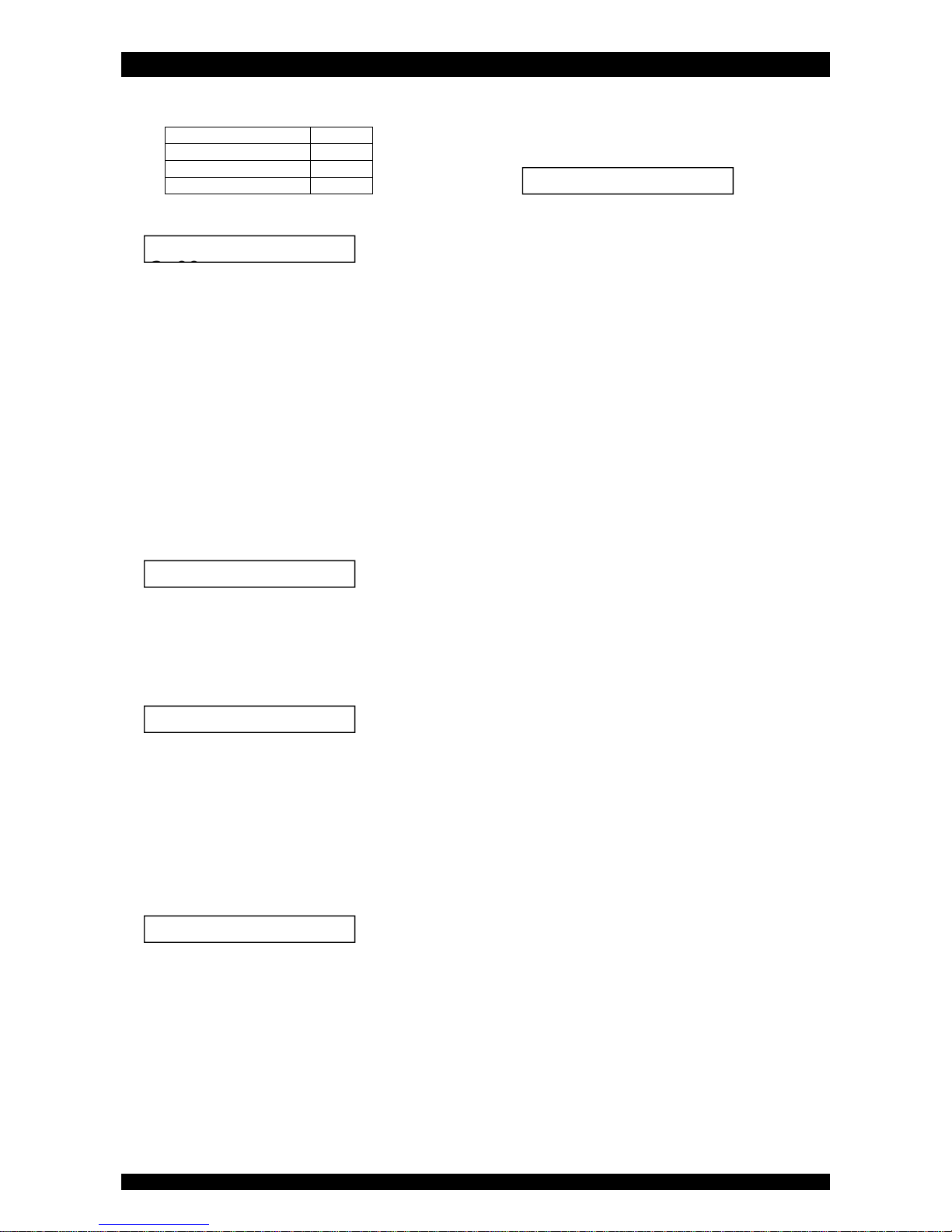
Eco Refill Cycle 1
Brine preparation
Cycle 2
Brine draw/slow rinse
Cycle 3
8. Press the scroll button again; the display will show:
Press the up or down button to set the
regeneration mode:
Dlyd/Immd: when the remaining capacity equals
the reserve capacity, a delayed regeneration is
started at the programmed time of regeneration;
however when the remaining capacity equals 0
before the programmed time of regeneration is
reached, an immediate regeneration is started.
Immediate: when the remaining capacity equals
0, an immediate regeneration is started.
Delayed: when the remaining capacity equals the
reserve capacity, a delayed regeneration is
started.
9. Press the scroll button again; the display will show
(only when the regeneration mode was set to 'Delayed' or
'Dlyd/Immd'):
Press the up or down button to set the time of
regeneration.
10. Press the scroll button again; the display will show
(only when the regeneration mode was set to 'Dlyd' or
'Dlyd/Immd'):
Press the up or down button to set the reserve
capacity:
Variable: the reserve capacity is calculated
automatically, based on the registered daily water
usage.
Fxd: press the scroll button again and press the
up or down button to set the reserve
capacity to a fixed amount.
11. Press the scroll button again; the display will show:
Press the up or down button to set the function
of the auxilliary contact:
Regen: aux. contact is powered during entire
regeneration (does not include refill and brine
preparation cycles!).
Chlor.Cell: aux. contact is powered at start of
brine draw/slow rinse cycle. Press the scroll
button again and press the up or down
button to set the duration of activation of the
chlorination cell.
Maintenance: aux. contact is powered when
maintenance reminder is triggered.
Error: aux. contact is powered when timer failure
occurs.
12. Press the scroll button again; the display will show:
Press the up or down button to save the settings
into the NOVRAM® and exit the programming mode.
Regen @ 2:00
Exit
Regen:Dlyd/Immd
Rsrv Variable
AUX: Regen
Page 10
ELECTRONIC CONTROL PANEL
Page 10
DIAGNOSTICS MODE
In the Diagnostics mode several operating parameters
can be consulted; particularly during a service intervention,
these parameters can be helpful to identify the cause of a
problem or malfunction.
Before entering the Diagnostics mode, make sure that
the appliance is in service mode.
In case no button is pressed in a period of 5 min, the
control panel will automatically return to the service mode!
ACCESSING THE DIAGNOSTICS MODE
1. Press the scroll button and hold it for 6 sec until the
display shows:
2. Within 10 sec, press the down button; the display will
show:
You are now in the Diagnostics mode.
Press the scroll button to advance to the next
diagnostics parameter.
AVAILABLE DIAGNOSTICS PARAMETERS
Regen X days ago: number of days since last
regeneration.
In Srvc: total number of days in service.
# of Regens: number of regenerations since installation.
TotVol: total volume of treated water since installation.
LastSet: number of days since last change of configuration
parameter or hardness of incoming untreated water.
InstFlow: instantaneous flow rate through appliance.
AvgVol: calculated average daily water usage.
LastRgn@: consumed capacity at last regeneration.
Capacity: calculated capacity between regenerations.
MaintCnt: current status of maintenance reminder
counter (counting up).
MP Resets: number of resets of microprocessor.
Memory Reset: number of corrupt memory start-ups.
CapToUse: remaining capacity.
Fill: length of refill cycle of last regeneration.
Reserve: calculated reserve capacity.
EZ3P5f EZ3PB r14: software version.
EXITING THE DIAGNOSTICS MODE
1. Press the scroll button repeatedly until the display
shows:
Press the up or down button to exit the
Diagnostics mode.
Exit
Regen XXdays ago
System Check
Page 11
MAINTENANCE
Page 11
RECOMMENDATION
Notwithstanding the reliability of the appliance, we strongly
recommend to have it serviced and maintained on a regular
basis by a competent and duly trained technician. He will be
able to determine the appropriate maintenance interval for
the appliance, depending on your specific application and the
local operating conditions. The advantages of performing
regular maintenance are:
regular check of the local operating conditions (water
quality, pressure, etc);
regular control and adjustment of the settings of the
appliance, to guarantee it operates at maximum
efficiency;
minimize the risk of unexpected break-down.
Contact your dealer or installer for more information, or visit
our website.
ROUTINE CHECKS
Regularly the user should perform a basic check to verify if the
appliance is functioning correctly, on the basis of the
following control points:
1. Check settings of electronic control panel.
2. Measure water hardness before/after appliance.
3. Check drain line from control valve; there shouldn’t be
any water flow (unless appliance is in regeneration).
4. Check drain line from brine cabinet overflow; there
shouldn’t be any water flow.
5. Check appliance and surrounding area; there shouldn’t be
any water leakages.
BYPASSING THE APPLIANCE
Occasionally it may be necessary to put the appliance
hydraulically in bypass, i.e. to isolate it from the water
distribution system; f.e.:
in case of an urgent technical problem;
when it is not necessary to supply treated water to the
house/application (refill swimming pool, irrigation,...).
WITH FACTORY BYPASS (optional)
Picture 9.a
SERVICE POSITION
= inlet valve to appliance is OPEN
= outlet valve from appliance is OPEN
Picture 9.b
BYPASS POSITION
= inlet valve to appliance is CLOSED
= outlet valve from appliance is CLOSED
Picture 9.c
MAINTENANCE POSITION
= inlet valve to appliance is OPEN
= outlet valve from appliance is CLOSED
WITH 3-VALVE BYPASS SYSTEM (not included)
Picture 10.a
SERVICE POSITION
= bypass valve is CLOSED
= inlet valve to appliance is OPEN
= outlet valve from appliance is OPEN
Picture 10.b
BYPASS POSITION
= bypass valve is OPEN
= inlet valve to appliance is CLOSED
= outlet valve from appliance is CLOSED
Picture 10.c
MAINTENANCE POSITION
= bypass valve is OPEN
= inlet valve to appliance is OPEN
= outlet valve from appliance is CLOSED
WATER CONDITIONER SALT
Picture 11
The appliance needs 'brine' for its periodic regenerations. This
brine solution is made from water, that is automatically dosed
in the brine cabinet by the control valve, and water
conditioner salt. The user should make sure that the brine
cabinet is always kept full of water conditioner salt. Therefore
he should periodically check the salt level inside the brine
cabinet and refill it if necessary. The salt lid can be removed
completely to facilitate refilling.
Ideally the level of water conditioner salt inside the brine
cabinet is kept between 1/3 and 2/3. A lower level of water
conditioner salt can cause insufficient brine saturation,
resulting in a loss of softening capacity. A higher level of water
conditioner salt can cause salt bridging (hard crust or salt
bridges in the brine cabinet). When you suspect salt bridging:
carefully pound on the outside of the brine cabinet to
break loose the salt bridges;
using a broom (or like blunt tool) carefully push the salt to
break it apart;
pour warm water over the top of the salt to dissolve it.
APPEARANCE
To retain the appearance of the appliance, simply wipe it with
a damp cloth or clean it with a mild soap solution; never use
abrasive cleaners, ammonia or solvents.
RESIN CLEANER
Other contaminants (f.e. iron) present in the feed water can
cause the resin bed to foul up, resulting in a loss of softening
capacity. An approved resin cleaner can be used periodically
to thoroughly clean the resin bed.
Page 12

MAINTENANCE
Page 12
SANITIZING THE APPLIANCE
This appliance is manufactured from premium quality
material and assembled in safe conditions to assure it is clean
and sanitary. If installed and serviced correctly, this appliance
will not infect or contaminate your water supply. However, as
in any 'device' plumbed-in in your water distribution system,
a proliferation of bacteria is possible, especially in case of
'stagnant water'. Therefore this appliance is equipped with a
'days override' feature, that will automatically rinse the resin
bed periodically, even in case of low or absence of water
usage.
If the power supply to the appliance is disconnected for a
longer period of time, we recommend, when the power
supply is re-established, to manually initiate a complete
regeneration.
Page 13
HYDRAULIC FLOW DIAGRAMS
Page 13
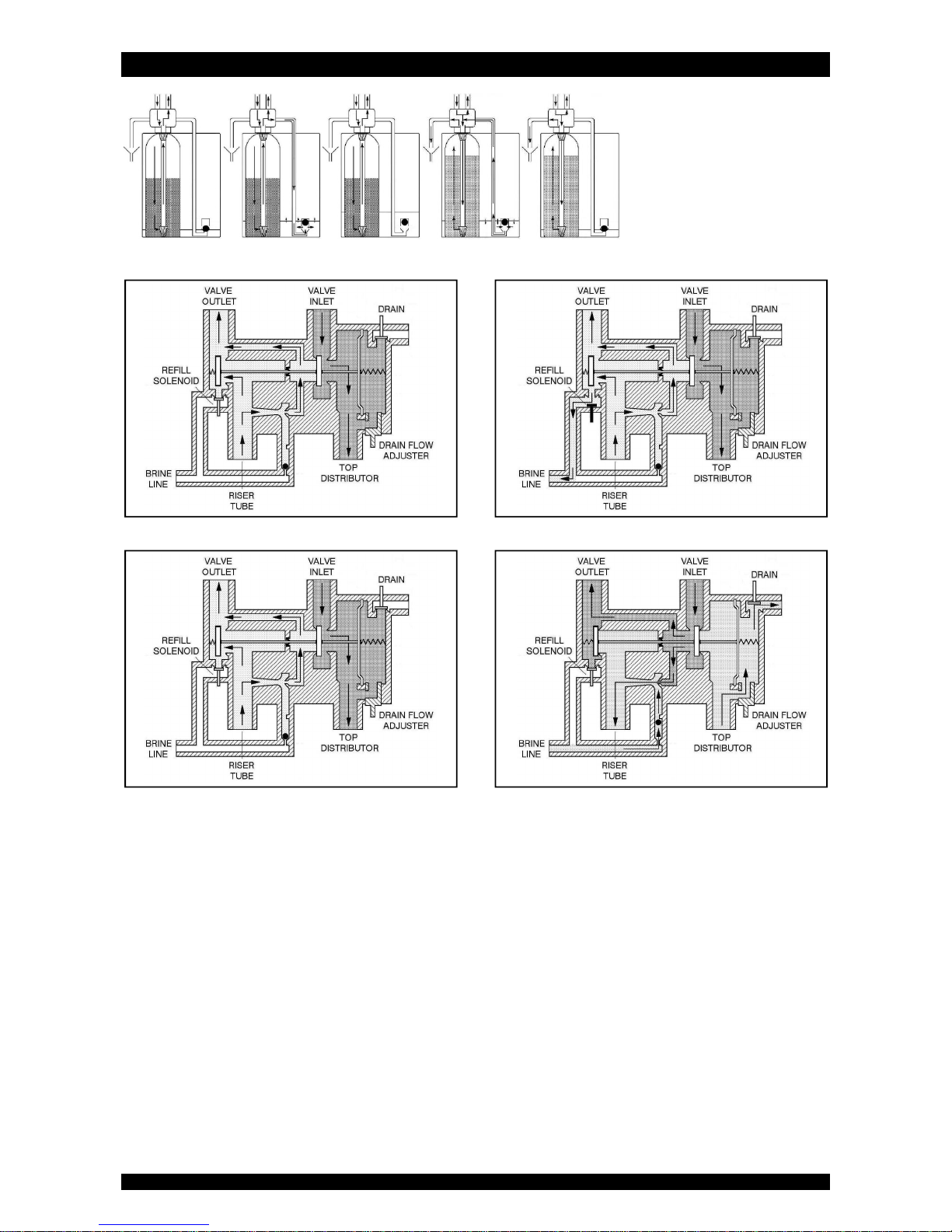
SERVICE REFILL BRINE PREP. BRINE DRAW SLOW RINSE
SERVICE REFILL
BRINE PREPARATION BRINE DRAW / SLOW RINSE
Page 14
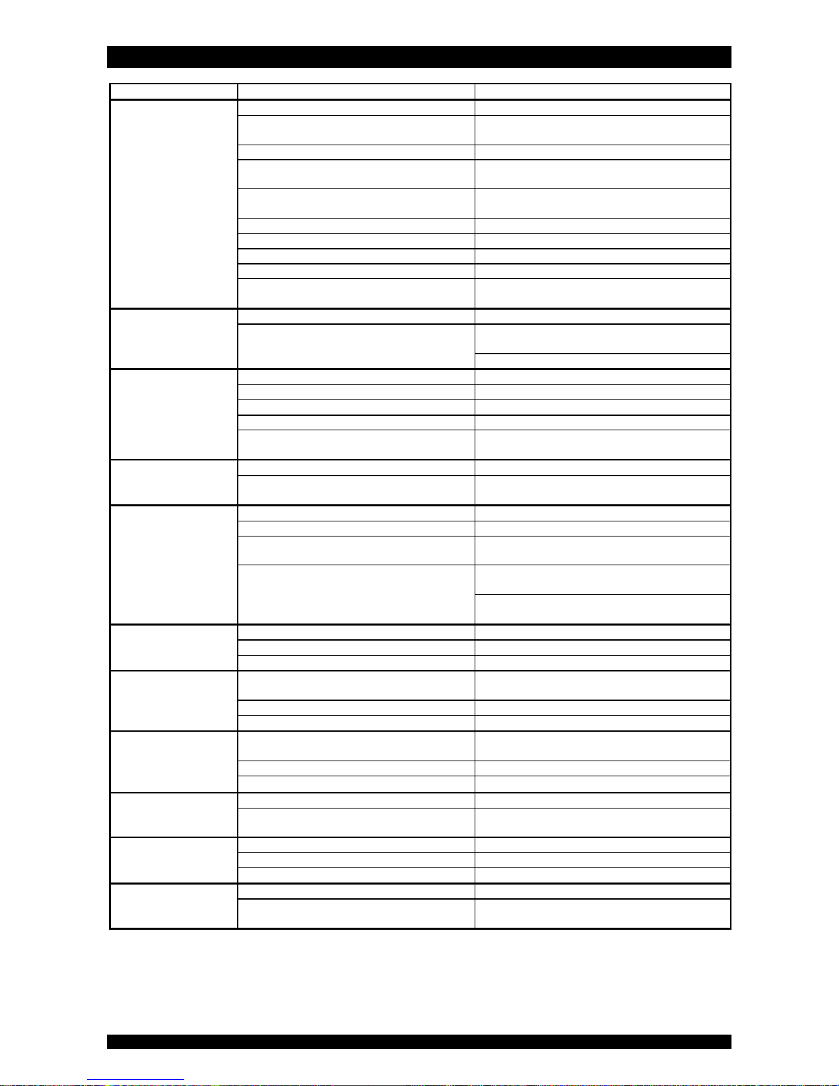
TROUBLESHOOTING
Page 14
PROBLEM
CAUSE
SOLUTION
Hard (untreated) water
to service
Open or defective bypass
Close
or replace
bypass
Appliance
in
regeneration
Wait until regeneration finishes or
manually
advance regeneration to end
No salt in brine
cabinet
Add salt an
d initiate regeneration manually
Salt bridging
Break salt bridge(s)
and initiate regeneration
manually
Change in raw water
hardness
Measure
the
hardness
of the incoming untreated
water and adjust programming accordingly
Appliance
fails to
r
egenerat
e Refer to problem “
Appliance
fails to
regenerate
” Improper brine draw
Refer to problem “
Improper brine draw
” Decreasing
exchange capacity of resin
Clean or replace resin bed
Loss of resin
Refer to problem “Loss of resin”
Leak at riser tube
Verify that riser tube is seated correctly and is not
cracked
Residual hardness in
treated water
Bypass not completely closed
Close bypass
Appliance is overrunning its softening capacity
Measure
the
hardness
of the incoming untreated
water and adjust programming accordingly
Verify operation of flow meter
Appliance
fails to
regenerate
Faulty electrical supply
Verify
electrical service (fuse, transformer,...)
Defective flow meter
Verify operation of flow meter
Defective PCB
Replace PCB
Defective drain solenoid
Replace drain solenoid
Control valve does not switch to regeneration
position
C
heck operating
pressure; must be higher than 1,4
bar
Appliance
uses too
much salt
Excessive water in brine
cabinet
Refer to problem “Excessive water in brine
cabinet
” System
regenerates too frequently
Measure
the
hardness
of the incoming untreated
water and adjust programming accordingly
Excessive water in
brine cabinet
Improper brine draw
Refer to problem “
Improper brine draw
” Improper setting
of refill cycle
Verify
setting of re
fill
cycle
Missing refill flow control
Verify that
refill
flow control is
installed and
properly sized
Leak from
control valve to brine cabinet
Clean or replace plunger and solenoid diaphragm of
refill solenoid
Check seal between brine draw check ball and brine
draw restrictor
Salt taste in treated
water
Improper setting
of brine draw/slow rinse cycle
Verify
setting of brine draw/slow rinse cycle
Excessive water in brine tank
Refer to problem “Excessive water in brine tank”
Improper brine draw
Refer to problem “
Improper brine draw
” Loss of water pressure
Mineral or
iron build
-
up in resin tank
Clean resin bed and control valve; increase
regeneration frequency
Plugged lower and/or upper distributor
Verify that distributors are free of debris
Crushed lower and/or upper distributor
Replace distributor(s)
Drain
line from control
valve flows
continuously
Appliance
in regeneration
Wait until regeneration finishes or
manually
advance regeneration to end
Drain solenoid stuck in open position
Clean drain solenoid
Defective PCB
Replace PCB
Drain line from
brine
cabinet overflow flows
continuously
Excessive water in brine cabinet
Refer to problem “Excessive water in brine
cabinet
” Leak between control valve and pressure tank
Verify seal between control valve and pressure tank
Control v
alve fails to
refill brine tank
Improper setting
of refill cycle
Verify
setting of re
fill
cycle
Plugged refill flow control
Clean refill flow control
Refill solenoid not opening
Verify operation of refill solenoid
Loss of resin
Lower and/or upper distributor damaged
Replace
distributor(s)
Leak between riser tube and upper distributor
Verify that riser tube is seated correctly and is not
cracked
Page 15

TROUBLESHOOTING
Page 15
PROBLEM
CAUSE S
OLUTION
Improper brine draw
Low operating pressure
Check operating pressure; must be higher than 1,4
bar
Plugged injector and/
or brine
draw
restrictor
Clean injector and/
or brine
draw restrictor
Plugged injector filter
Clean injector filter
Restricted drain line
Verify drain
line for kinks or restrictions
Restricted brine line
Verify brine line for kinks or restrictions
Leak in brine line
Verify brine line and connections for air leakage
No
water in brine tank
Refer to problem “Control v
alve fails to refill brine
tank”
Page 16
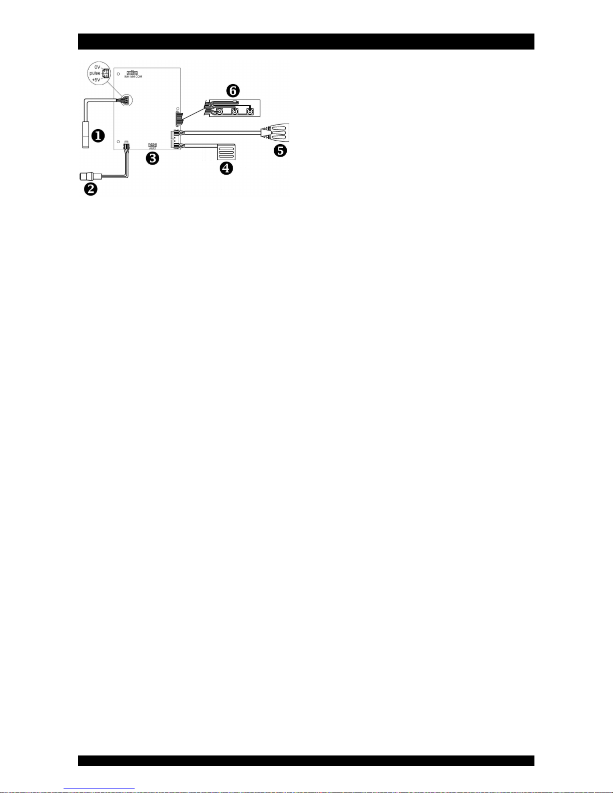
ELECTRICAL WIRING DIAGRAM
Page 16
= flow meter
= power lead
= auxilliary contact (24 VAC, max. 500mA)
= refill solenoid (white)
= drain solenoid
= key pad
Page 17
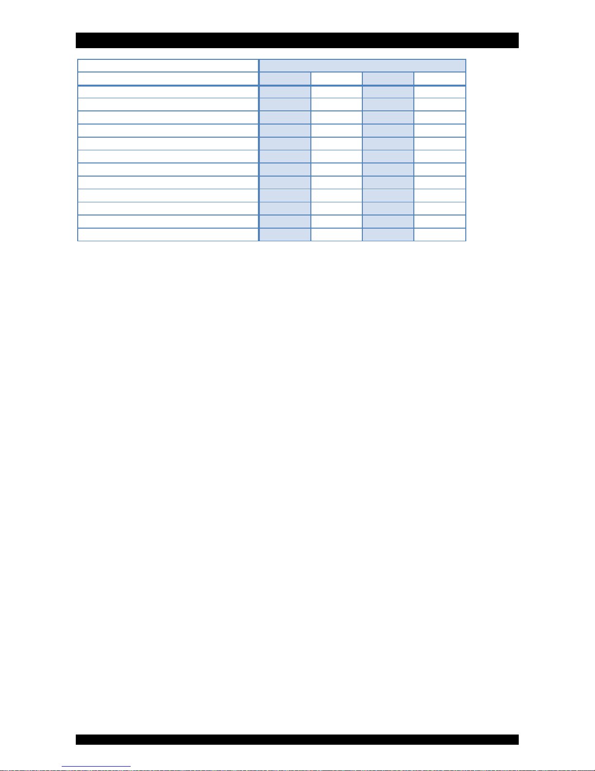
DEFAULT CONFIGURATION PARAMETER SETTINGS
Page 17
Model H2O-CS-EcoResin 9 12 18 26
Units Metric
Metric
Metric
Metric
MaintInt (mths) OFF OFF OFF OFF
Exchange capacity per liter resin (°f M3/L)
(1) (2)
3,5 4,0 4,5 4,5
Resin (liters) 9 12 18 26
Override (days) 7 7 7 7
Cycle 1: REFILL (sec)
(2)
198 264 396 572
Cycle 2: BRINE PREPARATION (min) 15 15 15 15
Cycle 3: BRINE DRAW/SLOW RINSE (min) 45 50 75 110
Regen Dlyd/Immd Dlyd/Immd Dlyd/Immd Dlyd/Immd
Regen @ 2:00 2:00 2:00 2:00
Rsrv Variable Variable Variable Variable
Auxilliary contact Regen Regen Regen Regen
(1) When the Hardness Unit is changed in the Basic Settings, the Exchange capacity per liter resin is automatically converted to the new Hardness Unit.
(2) When the Exchange capacity per liter resin is changed, the refill cycle time needs to be adjusted accordingly.
Page 18
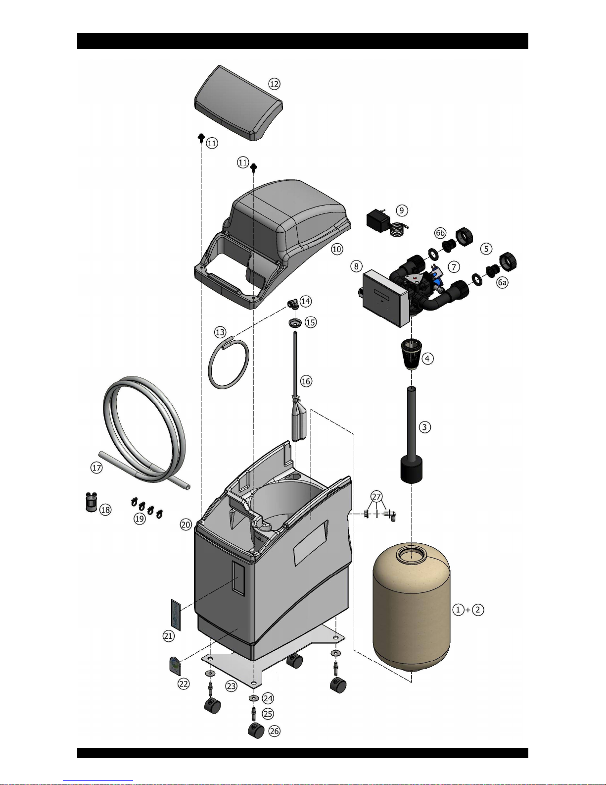
EXPLODED VIEW - SYSTEM
Page 18
Page 19
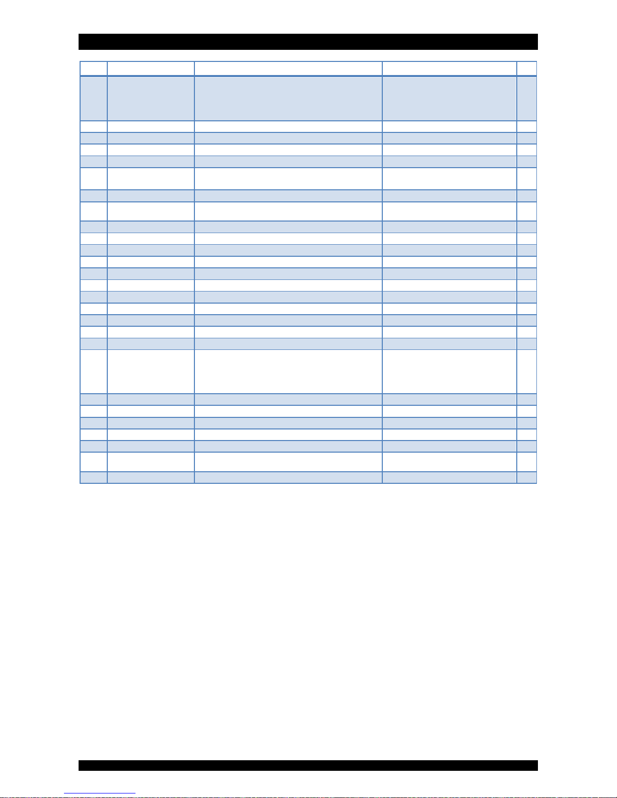
EXPLODED VIEW - SYSTEM
Page 19
Item PN Description Remark (*)
1 PT/0913/CP Pressure tank 9x13 9L
PT/0916/CP Pressure tank 9x16 12L
PT/0922/CP Pressure tank 9x22 18L
PT/0932/CP Pressure tank 9x32 26L
2 E8000 Softening resin
3 38528 Riser tube assembly with deflector to be cut to length
4 287/166 Top distributor
5 568/232 Nut, connection kit (2x)
6a 39078 Inlet adaptor ¾” BSP male plastic, with check valve
6b 39079 Outlet adaptor ¾” BSP male plastic, with check valve
7 71110 Gasket, connection kit (2x)
8
541N89/J90
541N89/J80
Control valve assembly
Control valve assembly
9L
12L, 18L, 26L
9 28/298/11 Transformer 230/24V - 50 Hz, 24VA, EuroT plug
10 39040 Cover
11 38547 Screw rivet (2x)
12 39041 Salt lid
13 H1015/2 Brine line polytube to be ordered per meter
14 DM/A6EU6 Quick-fit elbow 3/8”
15 38560 Plastic cap
16 74269 Air check assembly to be cut to length
17 38522 Drain hose to be ordered per meter
18 74163 Air gap with double hose barb
19 74174 Clamp, drain hose (4x)
20 39009 Cabinet body, micro 9L
39080 Cabinet body, mini 12L
39011 Cabinet body, midi 18L
39012 Cabinet body, maxi 26L
21 39054 Dome label ‘H2Optimo’
22 39004 Dome label ‘erie water treatment’
23 39076 Aluminum cabinet support only for 9L, 12L
24 39075 Washer M8x30 (x4) only for 9L, 12L
25 39073 Mounting pin, swivel caster (x4) only for 9L, 12L
26 39072
39071
Swivel caster, without brake (x2)
Swivel caster, with brake (x2)
only for 9L, 12L
only for 9L, 12L
27 38532 Overflow assembly
(*) Recommended Spare Part
Page 20
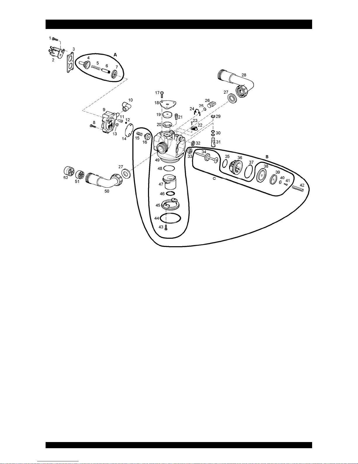
EXPLODED VIEW - VALVE BODY ASSEMBLY
Page 20
Page 21

EXPLODED VIEW - VALVE BODY ASSEMBLY
Page 21
Item PN Description Remark (*)
1 15/90 Screw, solenoid retainer (4x)
2 413/134/24 Solenoid
3 541/229 Retainer, solenoid
4 413/58 Guide, solenoid
5 413/62 Spring, solenoid plunger
6 74099 Plunger, solenoid
7 74098 Diaphragm, solenoid
8 15/222 Screw, back cap (4x)
9 541/286/3 Back cap
10 74258 Brine elbow
11 74022 Brine draw restrictor 1,0 mm (black)
12 541/275 Check ball
13 568/385/2/A Refill flow control 0,25 gpm
14 541/206 Gasket, back cap
15 541/239 Spring, check disc
16 541/246 Check disc
17 15/89 Screw, cover plate (3x)
18 541/221 Cover plate, injector
19 428/5 Injector disc #5
20 541/325 Gasket, injector
21 74179 Filter, injector
22 72609 Locking plate, drain flow adjuster
23 15/76 Screw, locking plate
24 541/254 Spring clip
25 186/118 O-ring, brine plug
26 541/273 Brine plug
27 72467 Union gasket (2x)
28 72542 Elbow, inlet
29 19/19 Clip, drain flow adjuster
30 186/134 O-ring, drain flow adjuster (2x)
31 541/238 Drain flow adjuster
32 529/244 O-ring, drain port
33 467/216 Seal, body stem
34 72605 Body stem
35 185/024/1 O-ring, seat insert (small)
36 541/204 Seat insert
37 185/029/1 O-ring, seat insert (large)
38 72602 Main diaphragm
39 72507 Retainer, main diaphragm
40 72245 Washer, main diaphragm
41 72552 Screw, main diaphragm
42 516/221 Spring, main diaphragm
43 15/90 Screw, adapter ring (2x)
44 185/67/4 O-ring, tank
45 541/232 Adapter ring
46 185/214/1 O-ring, riser tube
47 541/218 Riser insert 1,050”
48 185/029/1 O-ring, riser insert
49 541/257/1 Valve body (incl. 467/216)
50 72543 Elbow, outlet
51 72544 Impeller
52 72545 Hub, Impeller
A RK/413 Repair kit solenoid diaphragm
B RK/541/244 Repair kit body stem and seat
C 72611 Repair kit body stem
(*) Recommended Spare Part
Page 22
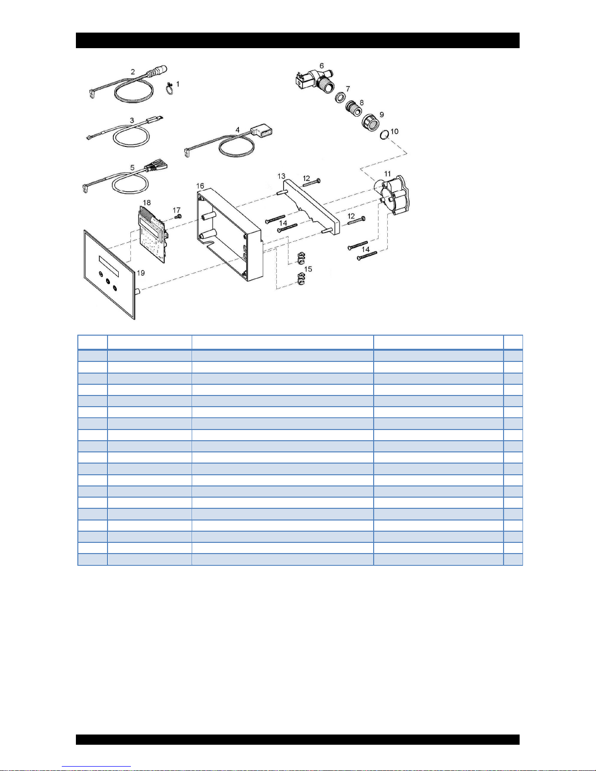
EXPLODED VIEW - VALVE HEAD & TIMER ASSEMBLY
Page 22
(*) Recommended Spare Part
Item PN Description Remark (*)
1 72263 Twist lock clamp, power cord
2 70971 Power cord
3 72519 Flow meter cable
4 71682 Refill solenoid cable (white)
5 72561 Drain solenoid cable
6 74023 Drain solenoid
7 74019 Gasket, drain solenoid
8 74016 Drain line adaptor
9 74018 Nut, drain solenoid
10 185/115/1 O-ring, drain line adaptor
11 15/87 Screw, valve head (4x)
12 72216 Valve head
13 74262 Screw, timer housing (2x) Standard metric thread (ISO)
14 74189 Timer mounting bracket
15 28/8/28 Strain relief (2x)
16 74026 PCB housing back
17 15/102 Screw, PCB (2x)
18 72788 Printed Circuit Board
19 74230 PCB housing front assembly Standard metric thread (ISO)
Page 23
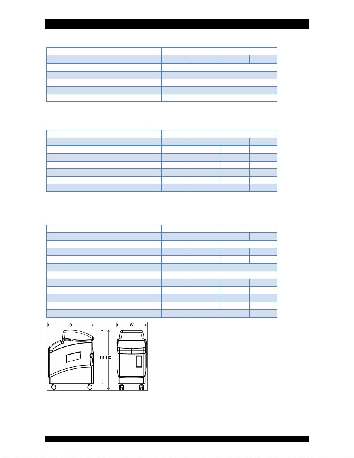
TECHNICAL DATA
Page 23
Technical specifications:
Model
H2O-CS-Eco-
Resin (Ltr) 9 12 18 26
Operating pressure min/max (bar)
(1)
1,4/5,0
Operating temperature min/max (°C)
(1)
2/65
Electrical connection (V/Hz) 230/50
(2)
Maximum power consumption (VA) 17
Hydraulic connection inlet/outlet ¾” BSP Male
(1) For cold water applications (max. 48 °C) max. operating pressure is 8,3 bar
(2) Supplied with 24V transformer
Performances @ 3 bar operating pressure
(3)
:
Model
H2O-CS-Eco-
Resin (Ltr) 9 12 18 26
Nominal exchange capacity (m³x°f) 32 48 81 117
Nominal exchange capacity (m³x°d) 18 26 45 65
Service flow rate @∆p 1 bar (m³/hr) 1,6 1,6 1,5 1,4
Recommended maximum service flow (m³/hr)
(4)
0,9 1,2 1,8 2,6
Salt usage per regeneration (kg)
(5)
1,1 1,5 2,3 3,3
Rinse water usage per regeneration (Ltr)
(5)
49 54 82 120
(3) Indicative numbers, performances depending on operating conditions and water quality
(4) Flow rate at which softening process is still executed adequately
(5) Maximum salt/water usage as brining is proportional (minimum of 60%)
Dimensions & weights:
Model
H2O-CS-Eco-
Resin (Ltr) 9 12 18 26
Width (mm) (W) 280
Height (mm) (H1) 513 591 744 998
Height, including wheels (mm) (H2) 567 645 N/A N/A
Depth (mm) (D) 438
Depth, including bypass (mm) 540
Height inlet/outlet (mm) 375 453 606 860
Height inlet/outlet, including bypass (mm) 381 459 612 866
Weight (kg) 15,5 20,0 26,5 36,0
Weight, including bypass (kg) 16,0 20,5 27,0 36,5
Maximum salt storage capacity (kg) 13 17 23 35
Page 24

Manufactured & Assembled by
erie water treatment
a division of Aquion, Inc.
www.eriewatertreatment.com
 Loading...