

Page 1
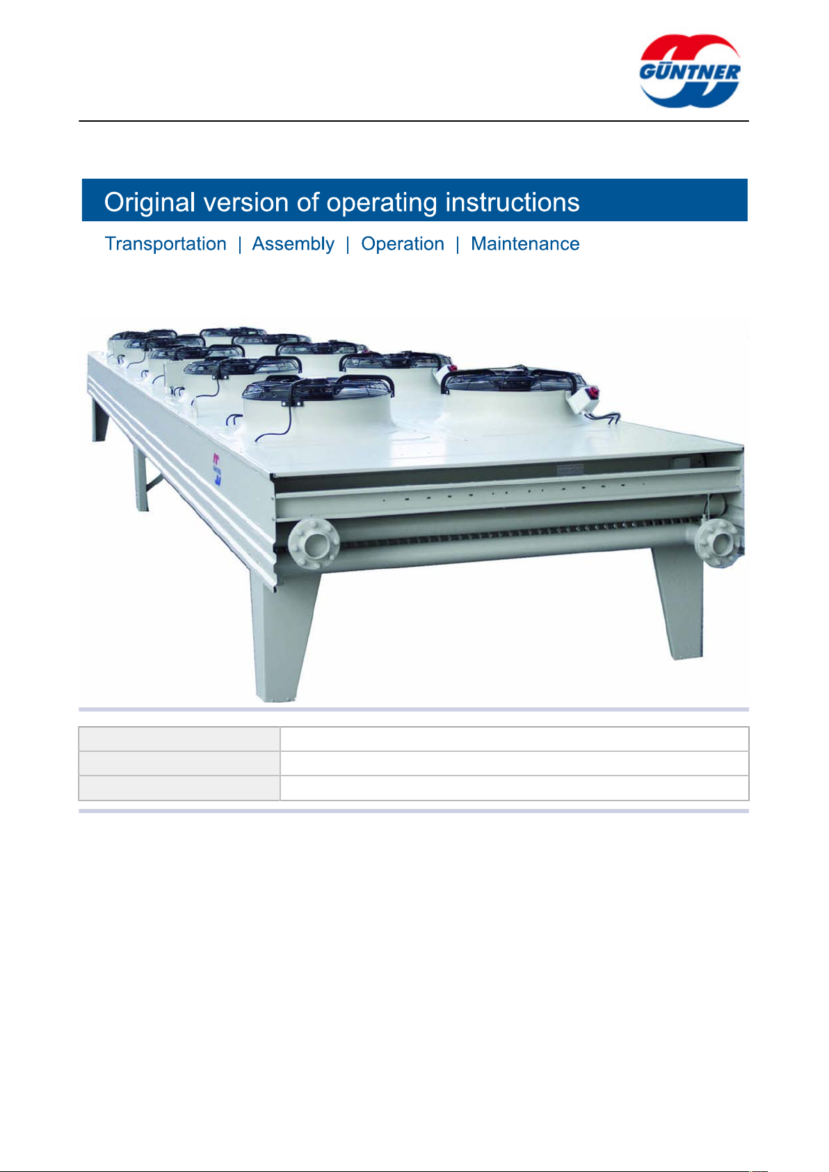
Drycoolers – GFH
Product line: Drycooler
Series variant description: Drycooler - Axial, Horizontal
Series: GFH
www.guentner.de
GFH | 2010-09
Page 2

Contents
page 2 / 59
1 Important basic information........................................................5
1.1 Safety instructions............................................................................. 5
1.1.1 Observing operating instructions.......................................................... 5
1.2 Importance of the EN 378 series of standards – refrigeration sys-
tems and heat pumps – safety-related and environmental require-
ments................................................................................................... 5
1.3 Responsibilities.................................................................................. 5
1.3.1 Manufacturer's responsibilities............................................................. 5
1.3.2 Responsibilities of the system's installer.............................................. 6
1.3.3 Owner or operator responsibilities....................................................... 6
1.4 Legal notes..........................................................................................7
1.5 Operating instructions....................................................................... 7
1.5.1 Scope....................................................................................................7
1.5.2 Set-up and other applicable documents.............................................. 7
1.6 Conventions........................................................................................ 8
1.6.1 Typographical conventions................................................................... 8
1.6.2 List of abbreviations............................................................................. 8
1.7 Conventions for safety signs and notices.......................................9
1.7.1 General safety signs and their meaning in these operating instruc-
tions...................................................................................................... 9
1.7.2 Warning signs and their meaning in these operating instructions.........9
1.7.3 Prohibitory signs and their meaning in these operating instruc-
tions.................................................................................................... 10
1.7.4 Mandatory signs and their meaning in these operating instruc-
tions.................................................................................................... 10
2 Safety........................................................................................... 12
2.1 Labelling on the unit:.......................................................................12
2.1.1 Safety signs on the unit..................................................................... 12
2.1.2 Other signs and notes on the unit......................................................13
2.2 Basic safety notices.........................................................................15
2.2.1 How to act in an emergency.............................................................. 15
2.2.2 Personnel, care requirements............................................................ 16
2.3 Proper intended use.........................................................................16
2.3.1 Proper intended use........................................................................... 16
2.3.2 Operating conditions...........................................................................16
2.3.3 Improper use...................................................................................... 17
2.4 Mechanical residual hazards...........................................................18
2.4.1 Fins, sharp unit corners and edges................................................... 18
2.4.2 Fans.................................................................................................... 19
2.5 Electrical residual hazards.............................................................. 19
2.6 Thermal residual hazards................................................................ 20
GFH | 2010-09
© Güntner AG & Co. KG
Page 3

page 3 / 59
2.6.1 Danger of burns................................................................................. 20
2.6.2 Frostbite hazard..................................................................................20
2.7 Residual hazards with the brine glycol..........................................20
2.8 Residual hazards caused by vibrations.........................................22
2.9 Residual hazards caused by pressurised parts............................22
2.10 Residual hazards caused by defective installation.......................23
2.11 Residual hazards with break during operation............................. 24
2.12 Residual hazards caused by escaping objects or liquids............ 24
2.13 Residual hazards with disposal...................................................... 25
3 Technical data............................................................................. 26
3.1 Unit..................................................................................................... 26
3.2 Fans....................................................................................................26
4 Set-up and function....................................................................28
5 Fan motor.................................................................................... 29
6 Transportation and storage....................................................... 30
6.1 Safety................................................................................................. 30
6.2 Transportation and storage.............................................................30
6.3 Storage before installation.............................................................. 32
7 Set-up and start-up.................................................................... 33
7.1 Safety................................................................................................. 33
7.1.1 Safety instructions for set-up and start-up......................................... 33
7.1.2 System-side safety requirements....................................................... 34
7.1.3 Customer-side safety precautions...................................................... 35
7.2 Requirements at the set-up point...................................................36
7.3 Unpacking the unit........................................................................... 41
7.4 Installation......................................................................................... 42
7.4.1 System-side requirements for stress-free installation........................ 42
7.4.2 Mounting the unit................................................................................42
7.5 Notes on connecting the unit......................................................... 43
7.5.1 Operation with water spray system....................................................43
7.5.2 Connect the unit to the heat carrier circuit of the system................... 43
7.5.3 Unit electrical connection and protection........................................... 44
7.6 Perform acceptance test..................................................................45
7.7 Test readiness for operation........................................................... 46
7.8 Putting the unit into operation for the first time........................... 46
GFH | 2010-09
8 Operation..................................................................................... 47
8.1 Safety................................................................................................. 47
8.2 Putting the unit into operation........................................................47
8.3 Taking the unit out of operation..................................................... 47
8.4 Shutting the unit down.................................................................... 48
© Güntner AG & Co. KG
Page 4

page 4 / 59
8.5 Putting the unit into operation after a shutdown.......................... 49
8.6 Changing the unit over to another working fluid.......................... 49
9 Troubleshooting..........................................................................50
9.1 Safety................................................................................................. 50
9.2 Service............................................................................................... 50
9.3 Troubleshooting table...................................................................... 50
10 Maintenance................................................................................ 51
10.1 Safety................................................................................................. 51
10.1.1 Before starting all maintenance..........................................................51
10.1.2 With all maintenance work................................................................. 51
10.1.3 After all maintenance work................................................................. 52
10.2 Inspection and maintenance plan.................................................. 53
10.2.1 Fans.................................................................................................... 53
10.2.2 Unit heat exchanger........................................................................... 53
10.3 Maintenance work............................................................................ 55
10.3.1 Remove leaks.....................................................................................55
10.4 Clean unit.......................................................................................... 55
10.4.1 General............................................................................................... 55
10.4.2 Clean heat exchanger........................................................................ 55
10.4.3 Cleaning fans......................................................................................58
11 Plans/diagrams........................................................................... 59
11.1 Electrics documentation..................................................................59
11.1.1 Fan motor connection diagram.......................................................... 59
11.2 Working fluidconnection diagram.................................................. 59
GFH | 2010-09
© Güntner AG & Co. KG
Page 5
page 5 / 59
1 Important basic information
1.1 Safety instructions
1.1.1 Observing operating instructions
CAUTION
Always keep the operating instructions in the unit's immediate vicinity at all times.
Ensure that the operating instructions are accessible to all people that have anything at all to
do with the unit at all times.
Ensure that the operating instructions are read and understood by all people that have anything at all to do with the unit.
1.2 Importance of the EN 378 series of standards – refrigeration systems and heat pumps – safety-related and environmental requirements
EN 378 deals with safety-related and environmental requirements for designing, constructing, producing, installing, operating, maintaining and disposing of refrigeration systems and cooling equipment.
EN 378 is oriented towards manufacturers, installers and operators of refrigeration systems and
cooling equipment (see section 1.2. Responsibilities).
The objective of EN 378 is to restrict the possible hazards of refrigeration systems, cooling equipment and their working fluids (refrigerants and coolants) for people, property and the environment
to a minimum.
Insufficient safety measures or non-compliance with safety-relevant regulations can result in:
•
Breaks or ruptures on components with the danger of escaping materials (hazards caused by
the influence of low temperatures, excess pressure, direct influence of the fluid phase, moving
machine parts).
•
Escaping working fluid after a break or leak because of defective design, improper operation, insufficient maintenance, repairs, filling and disposal (hazards caused by flammability, explosion
hazard, disturbance of nervous system, suffocation, panic)
1.3 Responsibilities
1.3.1 Manufacturer's responsibilities
The notes provided in these operating instructions on maintaining the unit's functional safety, preventing possible hazards when transporting, setting up and installing, start-up and operation, and
with maintenance activities (cleaning, servicing and repairing) refer exclusively to the unit.
The manufacturer's responsibilities are documented in the unit's version in acc. with EN 378-2 (design, manufacture and testing).
GFH | 2010-09
The construction, soldering and welding materials are configured so that they withstand the foreseeable mechanical, thermal and chemical stresses, and are resistant to the working fluid and the
working fluid/refrigerator oil mixture used.
© Güntner AG & Co. KG
Page 6

The working fluid-carrying parts of the unit (core tubes, distributor tube and header outlet) are configured so that they remain tight with the foreseeable mechanical, thermal and chemical stresses,
and withstand the maximum permissible operating pressure.
Material, wall thickness, tensile strength, corrosive resistance, shaping process and testing are suitable for the working fluid used and withstand the possible pressures and stresses that might occur.
All responsibilities regarding the equipment,, into which the unit is integrated, are the exclusive responsibility of the people involved in the individual workflows.
1.3.2 Responsibilities of the system's installer
The responsibilities of the system installer including the brine circuit/are documented in the
system's version (design, manufacture and testing – cooling equipment and refrigeration system) in
acc. with EN 378-2.
Component supplier-system installer interfaces :
•
Inform Güntner AG & Co. KG if faults occur:
Inform Güntner AG & Co. KG immediately if faults occur during the set-up, installation, start-up
and operation.
The responsibilities of the system installer in particular include:
page 6 / 59
•
Planning and preparing emergency measures:
To avoid consequential damage caused by operational disruptions, a warning system which immediately signals all faults must be provided on-site. Prepare emergency measures that prevent
consequential damage for people and property should faults occur.
•
Install emergency STOP switches that can be actuated without danger.
•
Specify checking and maintenance intervals:
The system including the brine circuit/(complete system:must be configured and equipped with
all required equipment for maintenance and sufficient servicing and testing in acc. with EN
378-4.
With the integration of the unit into the refrigeration system's brine circuit/ the working fluid and version must not deviate from the order-related information specified in the order-related offer documents.
The installer of the system including the brine circuit/must refer to the requirement for sufficient instruction of the operating and supervision staff when operating and maintaining the equipment .
It is recommended that the future customer staff – if possible – be present with the set-up and installation, with the tightness test and cleaning, with the filling with working fluid and with the setting
of the equipment including the brine circuit.
1.3.3 Owner or operator responsibilities
The owner or operator responsibilities are documented in the operation, maintenance, servicing
and recovery of the system including the brine circuit in acc. with EN 378-4.
GFH | 2010-09
The owner or operator must ensure that the proper people are sufficiently trained and qualified for
operating, monitoring and servicing the system including the brine circuit/.
The operating personnel for the system and the brine circuit must have sufficient knowledge and
experience with regard to the mode of operation, operation and daily monitoring of this system including the brine circuit .
© Güntner AG & Co. KG
Page 7
Before the system start-up including the brine circuit/the owner or operator must ensure that the operating personnel are sufficiently instructed with the system's documentation (which is part of the
operating instructions) on the set-up, monitoring, mode of operation and servicing of the system including the brine circuit/and the safety measures to be observed, and with regard to the properties
and handling of the working fluid to be used.
The owner or operator must ensure that when operating, monitoring and maintaining the system including the brine circuit the working fluid and version must not deviate from the details specified in
the order-related offer documents.
Planning and preparing emergency measures: To avoid consequential damage caused by operational disruptions, a warning system must be installed on the customer's premises. Prepare emergency measures that prevent consequential damage for people and property should faults occur.
Responsibility remains with the owner or operator of the system including brine circuit, if the system including brine circuitare used by somebody else, unless there is an agreement on sharing responsibility.
1.4 Legal notes
Warranty claim expires as follows:
page 7 / 59
•
With faults and damages that can be attributed to non-compliance with the specifications of
these operating instructions.
•
With complaints that can be attributed to use of spare parts other than the original spare parts
specified in the order-related offer documents.
•
With changes to the unit (working fluid, version, function, operating parameters) vis-a-vis the or-
der-related information specified in the order-related offer documents without the manufacturer's
prior consent.
The operating instructions may not be reproduced electronically or mechanically, circulated,
changed passed on to third parties, translated or used otherwise, in full or in part, without Güntner
AG & Co. KG's prior explicit written approval.
1.5 Operating instructions
1.5.1 Scope
1.5.2 Set-up and other applicable documents
These operating instructions apply for all drycoolers of the GFH series.
You will find the precise type of your unit in the attached order-related offer documents.
The unit's operating instructions include the following parts:
NOTICE
GFH | 2010-09
•
These instructions
•
Order-related offer documents
The order-related offer documents are attached to these instructions and include the following
information:
– The order-related proper use as specified
– The order-related scope of delivery
– The order-related technical data
© Güntner AG & Co. KG
Page 8
– The order-related drawings specifying customer, project number and order number
•
Motor connection wiring diagram in terminal boxes
These operating instructions are part of the operating instructions manual of the system, provided
by the system's installer including the brine circuit/.
1.6 Conventions
1.6.1 Typographical conventions
1.6.2 List of abbreviations
The following text markups are used in these operating instructions:
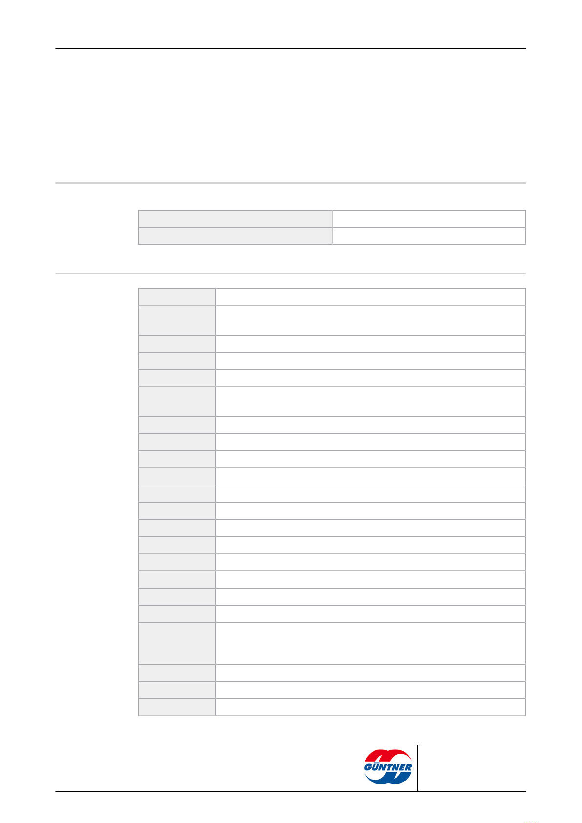
Bold Requires special attention!
Grey triangle Instructions
Abbreviations Meaning
EN 378 European Norm 378: Refrigeration systems and heat pumps; safety-related
and environmental requirements
page 8 / 59
EN European Norm
DIN German industrial standard (specification of a standard)
ISO International Standardization Organization
Emergency
STOP
°C Degrees Celsius (Celsius scale temperature)
bar Unit of pressure
I Litre (liquid volume)
Vol % Volume percent (concentration level relative to a volume)
IP Insulation protection
Q 6.3 Balancing quality
ppm parts per million, concentration figure, stands for "millionth"
Hz Hertz (frequency)
D Delta connection (rotating current: high speed)
S Star connection (rotating current: low speed)
3~ 3-phase rotating current
1~ 1-phase alternating current
Switch for immediately switching off the refrigeration system
GFH | 2010-09
VDE "Verband der Elektrotechnik, Elektronik und
Informationstechnik" (Association for Electrical, Electronic & Information
Technologies)
TCC Technical Connection Conditions
EPC Electric Power Company
VDI "Verein Deutscher Ingenieure" (German engineers' association)
© Güntner AG & Co. KG
Page 9
1.7 Conventions for safety signs and notices
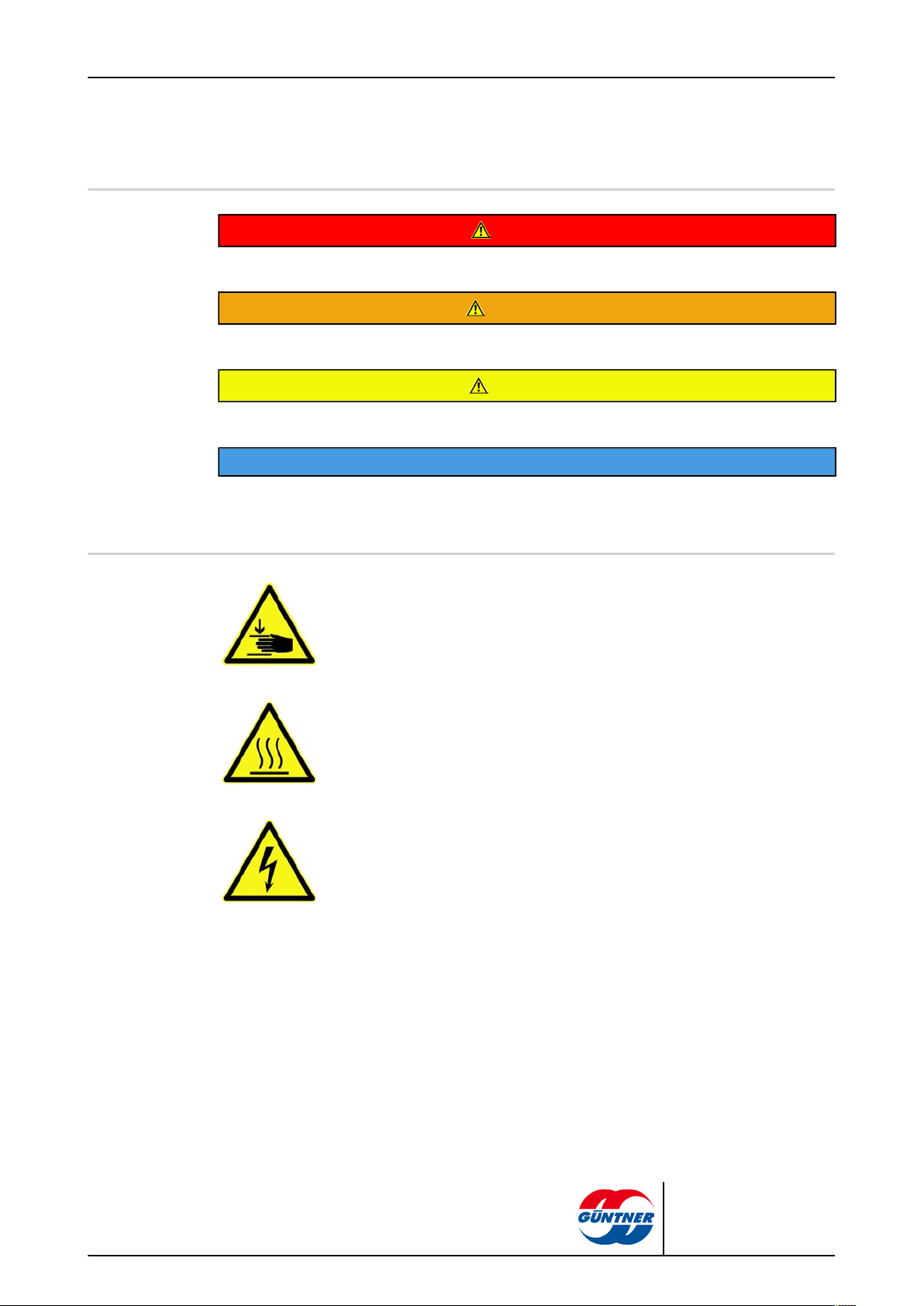
1.7.1 General safety signs and their meaning in these operating instructions
DANGER
Dangerous situation that will definitely cause serious injury or death if it is not avoided.
WARNING
Dangerous situation that could cause serious injury or death if it is not avoided.
CAUTION
Dangerous situation that could cause slight to moderate injury if it is not avoided.
NOTICE
Refers you to possible damage to property.
page 9 / 59
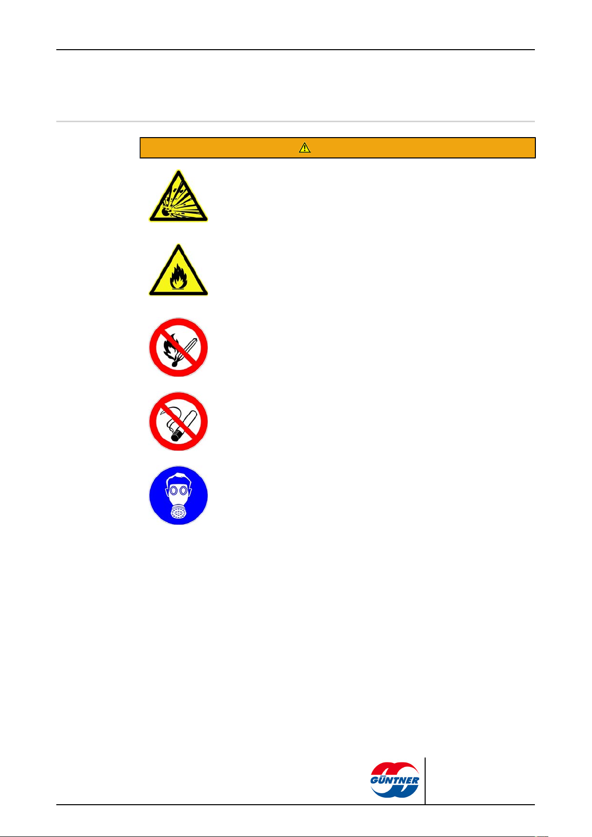
1.7.2 Warning signs and their meaning in these operating instructions
Warns against hand injuries!
Hands or fingers can be crushed, pulled in or otherwise injured with non-compliance.
Warns against hot surfaces!
The temperature is over +45 °C (protein clotting) and can cause burns.
Warns against dangerous electrical voltage!
Danger of an electric shock if voltage-carrying parts are touched.
GFH | 2010-09
© Güntner AG & Co. KG
Page 10
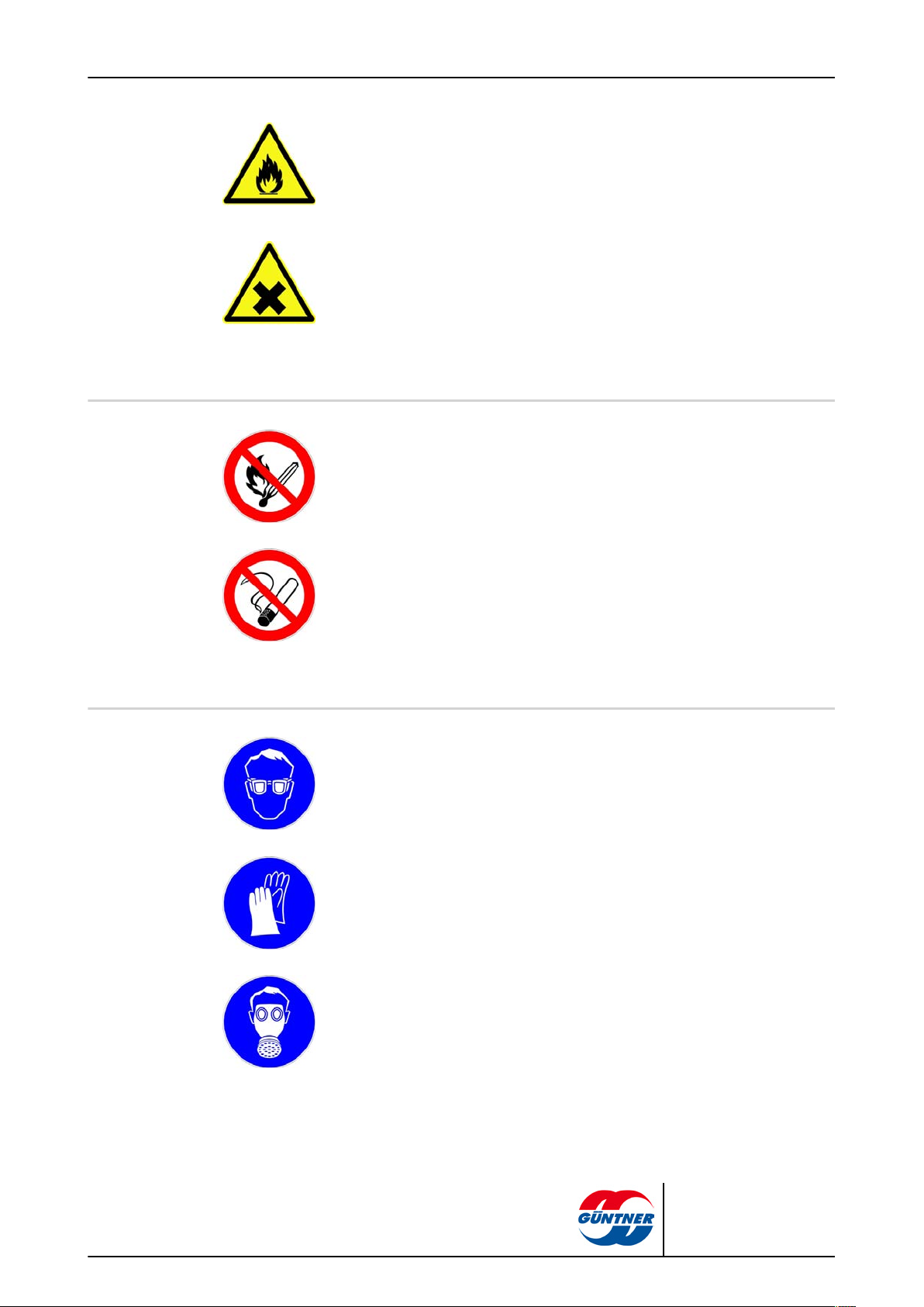
Warns against fire-risk substances at set-up point.
Use of ignition sources can cause fire at set-up point.
Warns against harmful to health or irritant substances at set-up point
Contact with or inhaling harmful to health or irritant substances can cause injuries
or damage the health.
1.7.3 Prohibitory signs and their meaning in these operating instructions
Feuer, offenes Licht und Rauchen verboten!
Ignition sources must be kept away and ignition sources must not develop!
page 10 / 59
No smoking!
Smoking is forbidden.
1.7.4 Mandatory signs and their meaning in these operating instructions.
Use eye protection!
Eye protection: Use protective cover, protective glasses or face protection.
Use hand protection!
Protective gloves must protect against mechanical and chemical dangers (see imprinted pictograms).
Use respiratory protection!
Breathing apparatus must be suitable for the working fluid used. Breathing apparatus must consist of:
•
At least two independent breathing devices (self-contained breathing apparatus)
GFH | 2010-09
© Güntner AG & Co. KG
Page 11
page 11 / 59
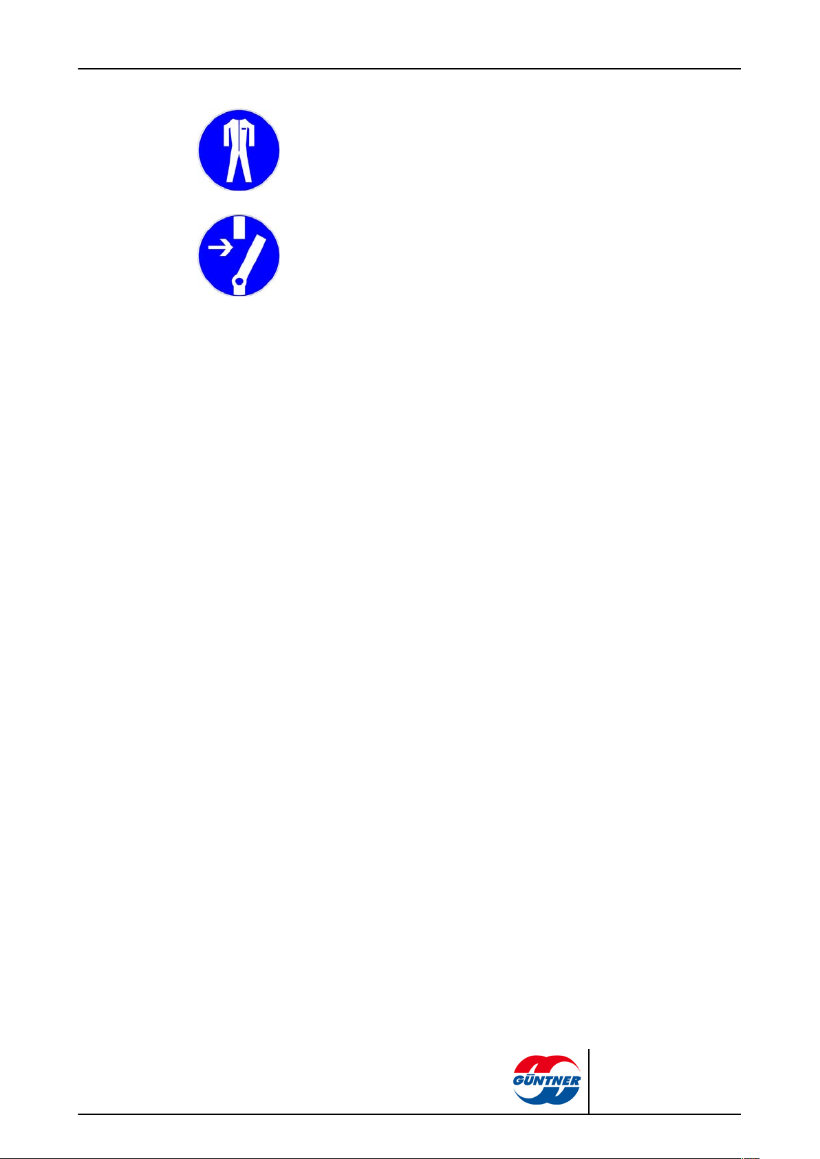
Use protective clothing!
Personal protective clothing must be suitable for the working fluid used and for low
temperatures, and must have good heat insulation properties.
Activate before work!
Activate the electrical system and secure against switching on again before starting installation, maintenance and repair work.
GFH | 2010-09
© Güntner AG & Co. KG
Page 12
2 Safety
2.1 Labelling on the unit:
1 Unit type plate on front plate 6 "Fan guard" warning sign – only with units
2 Güntner logo 7 Connections ON, OFF
3 "Transportation filling" warning sign next to
Schrader valve
4 Usage area for fork lifts; affix in the struts
area
5 Inspection door, only on units with inspec-
tion doors
page 12 / 59
with individual removable fan protection,
e.g. Woods fans.
8 Transportation regulation; affix on both
sides between the lifting lugs; also affix at
the front/end sides; and on the packaging
if required
11 Installation instructions for vibration
dampers (enclosed with vibration
dampers)
2.1.1 Safety signs on the unit
Safety signs on the unit individually:
3 - "Transportation filling" warning sign next to Schrader valve
GFH | 2010-09
© Güntner AG & Co. KG
Page 13
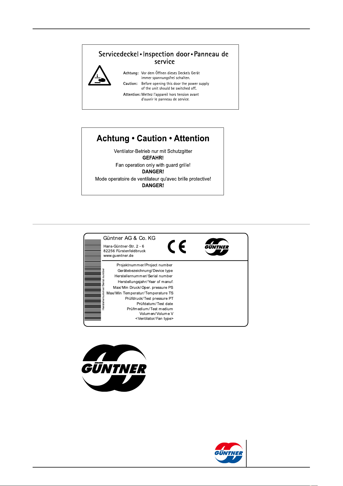
Note on inspection door (only with hinged fans)
page 13 / 59
7 - "Guard grille" warning sign (only used with separate removable guard grille)
2.1.2 Other signs and notes on the unit
1 - Unit type plate
GFH | 2010-09
2 – Güntner logo
© Güntner AG & Co. KG
Page 14
12 - Connections ON and OFF
page 14 / 59
GFH | 2010-09
21 - Transport regulation in acc. with SP 11
4 - Usage area for forklifts in acc. with SP 34
© Güntner AG & Co. KG
Page 15
2.2 Basic safety notices
2.2.1 How to act in an emergency
Danger of injuries and damage to property!
The unit is operated as standard with the brine, ethylene glycol (synonyms:
ethane-1,2-diol, glycol). When using other brines, prior agreement with the manufacturer is an absolute must.
Ethylene glycol is a colourless, slightly viscous, not very fluid, water-mixable,
deliquescent liquid with a sweet smell or taste.
Ethylene glycol is flammable and explosive at higher temperatures in a vapour/
gaseous state.
With skin contact ethylene glycol causes slight irritation with the danger of skin
absorption; with eye contact mucous membrane irritation; with ingestion agitation with disruption of the central nervous system; with prolonged endangering
effect – fatigue, coordination disruption, unconsciousness, kidney damage.
Keep ethylene glycol away from ignition sources. No smoking!
Ethylene glycol vapours are heavier than air and may flow off to rooms on a lower level. In still air there may be an increase of the ground level concentration.
With high concentrations, there is a danger of suffocation due to reduced oxygen concentration, especially at ground level.
Avoid contact with skin, floor, clothing! Remove contaminated, soaked clothing
immediately!
Do allow contact with heavy oxidation agents (chromo-sulphuric acid, potassium permanganate, smoking sulphuric acid, or similar)! Danger of strong reactions!
Unauthorised people must not have access to the unit. When setting up it must
be ensured that the brine/ escaping from the unit cannot penetrate the interior of
the building or put people at risk in any other way.
Safety measures and procedure:
•
With unexpected serious brine/ breaks, activate the emergency STOP switch
set up in a safe place, e.g. with:
– Visibly escaping brine from the heat exchanger or pipe components.
– Sudden large release (release and evaporation of the greater part of the
entire brine/ in a short time, e.g. in less than 5 minutes).
•
Have experienced, trained personnel with prescribed protective clothing perform all necessary protective and other measures:
– Use respiratory protection.
– Use a room air-independent breathing apparatus with maintenance work
in high brine/ concentrations in the room air.
– Ensure the set-up room is well ventilated.
– Divert escaped brine/ liquid safely in acc. with EN 378-3.
page 15 / 59
WARNING
GFH | 2010-09
© Güntner AG & Co. KG
Page 16
2.2.2 Personnel, care requirements
The unit must only be put into operation, operated, maintained and repaired by trained, experienced and qualified personnel. People that are responsible for the operation, maintenance, repair
and evaluation of systems and their components must have the required training and specialist
knowledge for their work in acc. with EN 378-1 to be qualified. Qualified or expert means the ability to satisfactorily perform the activities required for the operation, maintenance, repair and evaluation of refrigeration systems and their components.
The unit may be operated by operating personnel that have no specific knowledge of refrigeration
engineering, but have sufficient knowledge and experience with regard to the mode of operation,
operation and daily monitoring of this system, including the brine circuit . This operating personnel may not make any interventions or settings on the system including the brine circuit .
Changes to the unit, which the manufacturer has first agreed to in writing, may only be made by
the instructed and qualified personnel.
Electrical installation:
Work on the electrical equipment may only be performed by personnel that have the required expertise (e.g. an electrician or an electro-technically instructed person), and who are authorised by
the operator, in compliance with the respective VDE regulations (and national and international
provisions) and the TCCs of the EPCs.
page 16 / 59
CAUTION
2.3 Proper intended use
2.3.1 Proper intended use
2.3.2 Operating conditions
Drycoolers of the GFH series are intended for installation in the brine circuit of a refrigeration system and for outdoor installations. The drycoolers cool the brine by giving off heat to the air that is
being moved by fans over the dry heat exchanger surface.
The unit is delivered for operation with a specific operating point:
•
Brine flow temperature
•
Brine return temperature or circulating brine volume
•
Airflow volume
•
Air inlet temperature
The specified operating point is provided in the order-related offer documents.
The unit is a component of the heat carrier circuit a cooling system including its working fluid circuit.
The purpose of these operating instructions, as part of the operating instructions manual (of which
these operating instructions are a part), is to restrict the dangers to people and property and the environment from the unit and the working fluid used in it to a minimum. These dangers are essentially connected with the physical and chemical properties of the working fluid and with the pressures
and temperatures that occur in the working fluid-carrying components of the unit see Residual haz-
ards with the brine glycol, page 20.
GFH | 2010-09
© Güntner AG & Co. KG
Page 17
Danger of injuries and damage to property!
The unit must only be used in acc. with the proper intended use. The operator must ensure that
when operating, monitoring and maintaining the unit, the fluid and version do not deviate from the
order-related information specified in the order-specific offer documents.
The operator must ensure that maintenance measures are performed in compliance with the
system's operating instructions manual.
Filling the unit is only permitted following written approval by the manufacturer. You will find the
order-related proper use as intended in the order-specific offer documents.
Do not exceed the max. operating pressure given on the unit's type plate.
2.3.3 Improper use
page 17 / 59
WARNING
WARNING
Danger of injuries and damage to property!
Working fluids and their combinations with water or other substances in the working fluid-carrying components have chemical and physical effects from the inside on the materials surrounding
them. The unit must only pressurised with brine glycol. Pressurising the unit with another working fluid results in,
■
the structural, soldering and welding materials used do not withstand the foreseeable mechanical, thermal and chemical stresses, and the pressure that can occur during operation
and when shut down is not withstood.
■
material, wall thickness, tensile strength, corrosive resistance, shaping process and testing
are not suitable for the working fluid used and do not withstand the possible pressures and
stresses that might occur.
■
the unit not being resistant to the other working fluid and the other working fluid mixture.
■
the unit not remaining tight during operation and when shut down.
■
a possible sudden escaping of working fluids could directly endanger people and/or property
and the environment.
The maximum permissible operating pressure specified on the type plate must not be exceeded!
If the operating pressure is exceeded,
■
the structural and welding materials will not withstand the foreseeable mechanical, thermal
and chemical stresses and the pressure that can occur during operation and when shut down.
■
the unit will not remain tight during operation and when shut down.
■
there may be a possible sudden escaping of working fluids after a break or leakage on work-
ing fluid-carrying components, which would result in the following dangers:
– Danger of escaping materials
– Suffocation hazard
– Hazards caused by panic reactions,
– Environmental pollution
GFH | 2010-09
© Güntner AG & Co. KG
Page 18
page 18 / 59
WARNING
Drycoolermay not be used
■
where it is possible that short or prolonged effect caused by contact, inhalation or ingestion of
the working fluid glycol might result in harmful hazards.
■
where the possibility exists of a sudden large release of the greater part of the entire working
fluid filling in a short time (e.g. in less than 5 minutes).
The unit must not be changed without prior written consent by Güntner AG & Co. KG. Changes to
the unit are:
■
Changing the operating point (see chapter Unit)
■
Changing the fan capacity (air volume)
■
Changing the working fluid flow-through volume
■
Changing over to another working fluid
The unit must not be operated if safety devices recommended by the manufacturer are not available, not properly installed or not fully functional.
The unit must not be operated if it is damaged or demonstrates faults. All damages and faults
must be reported to Güntner AG & Co. KG immediately and must be removed immediately.
Work on the unit must not be performed without the personal protective equipment specified in
these operating instructions.
2.4 Mechanical residual hazards
2.4.1 Fins, sharp unit corners and edges
Warns against hand injuries!
Danger of cuts on hands and fingers on the fins and on sharp corners and
edges of the unit.
Use reliable hand protection!
WARNING
GFH | 2010-09
© Güntner AG & Co. KG
Page 19
2.4.2 Fans
page 19 / 59
WARNING
Danger of cutting off, pulling in!
There is a danger of cutting off fingers on the rotating fan blades, injury hazard
for the hands and pulling in danger for loose elements such as hair, necklaces
or clothing parts.
Do not operate fans without guard grille. Pinch/trap point hazard!
With automatic fan start during maintenance work there is a danger of pinching/trapping for the hands and fingers.
Power off the unit before you begin maintenance work with which you must remove the guard grille. Secure the unit against unintentional switching on again
by removing the electric fuses for the unit. Secure the unit with a suitable warning sign referring to unintentional switching on.
2.5 Electrical residual hazards
Warns against dangerous electrical voltage!
Direct and indirect contact with voltage-carrying parts of motors and electrical
lines can cause serious injuries or death.
Power off the unit before you begin maintenance work. See the refrigeration
system's system documentation for this. Secure the unit against unintentional
switching on again by removing the electric fuses for the unit. Secure the unit
with a suitable warning sign referring to unintentional switching on.
Please note that the mains cables may also be carrying voltage, even if the unit
is powered off.
Work on electrical equipment must only be performed by people that have the
required expertise (e.g. an electrician or an electro-technically instructed person) and who are authorised to do so by the operator.
WARNING
GFH | 2010-09
© Güntner AG & Co. KG
Page 20

2.6 Thermal residual hazards
2.6.1 Danger of burns
Warns against hot surfaces!
In operation the unit's heat exchanger and pipes have temperatures of over +45
°C. Contact can cause burns.
With brine temperatures over +45 °C there is the hazard of burns on pipe components and distribution pipes.
Use hand protection!
2.6.2 Frostbite hazard
page 20 / 59
WARNING
WARNING
Warns against frostbite!
With insufficient frost protection filling and operation in areas with frost hazard
the unit can cause frostbite. With units that cannot be drained completely the
hazard of frostbite also remains after draining. It is imperative that the proper
ventilation be ensured when draining the unit. With pressure test, operation and
shutdown of units filled with water or insufficient frost protection filling or insufficient setting of the brine/, these are disrupted at minus temperatures.
2.7 Residual hazards with the brine glycol
WARNING
Danger of injuries and damage to property!
General description of hazards:
The unit is operated as standard with the brine ethylene glycol (synonyms: ethane-1,2-diol, glycol) . When using other brine/coolants, brine prior agreement with the manufacturer is an absolute must.
Ethylene glycol is a colourless, slightly viscous, not very fluid, water-mixable, deliquescent liquid
with a sweet smell or taste.
Unauthorised people must not have access to the unit. When setting up it must be ensured that
the brine/ escaping from the unit cannot penetrate the interior of the building or put people at risk.
GFH | 2010-09
WARNING
Danger of harm to health!
With skin contact ethylene glycol causes slight irritation with the danger of skin absorption; with
eye contact mucous membrane irritation; with ingestion agitation with disruption of the central
nervous system; with prolonged endangering effect – fatigue, coordination disruption, unconsciousness, kidney damage.
© Güntner AG & Co. KG
Page 21
page 21 / 59
•
Avoid contact with skin, eyes and clothing! Remove contaminated, soaked clothing immedi-
ately!
•
Ethylene glycol vapours are heavier than air and may flow off to rooms on a lower level. In
still air there may be an increase of the ground level concentration. With high concentrations,
there is a danger of suffocation due to reduced oxygen concentration, especially at ground
level.
•
To avoid the inhalation of high vapour concentrations, the working rooms must be well aired.
•
Test the tightness of the unit regularly, as specified in these operating instructions.
Ignition and fire hazard!
Ethylene glycol is flammable and explosive at higher temperatures in a vapour/
gaseous state.
•
Keep ethylene glycol away from ignition sources.
•
Suitable fire fighting equipment must be provided on site with work involving
fire or sparks, such as grinding, welding, etc.
•
Ensure that the provided fire fighting equipment is provided in sufficient
quantities, that it functions properly and that the extinguishing agent does not
react with the brine/.
•
No smoking!
Danger of poisoning!
Contact of the brine/ with open fire must be prevented, as toxic combustion
products can form.
•
Prevent brine/ contact with open fire!
•
Welding and soldering must therefore only take place after completely draining the relevant section of the system of the brine/. Ensure good ventilation
here!
•
Do not bring into contact with heavy oxidation agents (chromo-sulphuric
acid, potassium permanganate, smoking sulphuric acid, or similar)! Danger of
strong reactions!
Frostbite hazard!
With insufficient frost protection filling and operation in areas with frost hazard
the unit can cause frostbite. With units that cannot be drained completely the
hazard of frostbite also remains after draining.
•
It is imperative that the proper ventilation be ensured when draining the unit.
•
With pressure test, operation and shutdown of units filled with water or insufficient frost protection filling or insufficient setting of the brine/, these are disrupted at minus temperatures.
GFH | 2010-09
© Güntner AG & Co. KG
Page 22

2.8 Residual hazards caused by vibrations
WARNING
Danger of injuries and damage to property caused by escaping materials
If fans are damaged during fan operation, flying parts of the fan blades can injure people or cause
damage to property close to the fan.
Fans, components and cables in the system, including the brine circuit must be designed, constructed and integrated so that dangers caused by vibrations that it or other parts of the system
generate are reduced to an absolute minimum, while incorporating all available means for reducing vibrations, preferably at the source.
NOTICE
Damage to property caused by vibrations
Vibrations that are increased by imbalances, as created by dirt or fan blade damage, are regularly
caused with fan operation. The vibrations are transferred to the unit, where they can cause damage and damage the unit mounting or brine circuit components connected to the unit.
page 22 / 59
Check the fan blades and guard grille regularly for dirt and frosting and/or icing and the fans'
smooth running (see Fans, page 53).
Check the fan blades and guard grille regularly for dirt and the fans' smooth running (see Fans,
page 53).
2.9 Residual hazards caused by pressurised parts
WARNING
Injury and damage to property caused by pressurised components that contain brine/!
Breaks in pressurised pipes or pressurised components of the unit can cause injuries or damage
to property caused by escaping materials. A sudden large release of the working fluid with its hazardous properties after a break or leak on pressurised components of the unit can cause the following hazards:
■
Irritations and health hazards
■
Strong chemical reactivity
■
Flammability
■
Suffocation
■
Panic,
■
Environmental pollution
Ensure that the unit in question is pressure-free before maintenance work begins or remove the
working fluid from the unit in question.
GFH | 2010-09
Only perform maintenance work – especially soldering and welding work – on the unit in question
after completely removing the working fluid from the unit.
© Güntner AG & Co. KG
Page 23

2.10 Residual hazards caused by defective installation
WARNING
Injuries and damage to property caused by defective installation!
Defective installation results in hazards caused by:
■
Break or leak on liquid-carrying unit components and pipes
■
Uneven load distribution on the fixtures with the danger of stresses within the unit or unit dis-
placement (breaks or leaks on fluid-carrying components of the unit and pipes; danger of
breaking off).
■
Insufficient securing of working fluid-carrying lines against mechanical damage! On-site con-
nections: loaded installation; effect of forces on the distribution and header pipes with the
danger of breaks or leaks on fluid-carrying components of the unit and pipes; danger of break-
ing off!
■
Break-off and fall danger of the unit with hazard of escaping working fluid and exposed electri-
cal cables.
■
Break-off danger of the unit with hazard of escaping working fluid and exposed electrical ca-
bles.
■
Danger of damage caused by environment-conditional hazard sources (production, transport
and other processes at the set-up point).
■
Unit functional faults caused by air inlet/outlet obstructions.
■
Obstruction of all-side inspection, checks and maintenance, i.e. no unobstructed accessibility
to the working fluid-carrying and electrical components, connections and cables, no recognis-
able identifiers on the pipes and insufficient space for tests.
Ensure that:
page 23 / 59
•
The units are to be installed on the fixing points corresponding with their weights and tight-
ened with fixing bolts. The operator or installer is responsible for ensuring that the bolted con-
nections are of an adequate strength.
•
The diameters of the mounting holes have been statically determined by the manufacturer and
the fixing bolts are adapted accordingly.
•
The fixing bolts are secured against loosening by means of an appropriate locking device.
•
The fixing bolts are not overtightened or stripped.
•
All fixing bolts are tightened equally to achieve a load distribution on the connections that is
as balanced as possible.
•
All fixing points maintain the same spacing to the fixing level permanently and under load, so
that no mechanical stress occurs in the unit structure. The units are anchored in their fixing
position in order to prevent the equipment from moving.
•
The functional safety of the fixing bolts is tested as part of the maintenance periods. see Main-
tenance, page 51.
•
The unit is fixed and set up so that it is not damaged by environment-conditional hazard
sources (production, transport and other processes at the set-up point) or its functioning is
not disturbed by the interventions of unauthorised persons.
•
The units are fixed and set up with sufficient slopes for drip water flow.
•
The units are fixed and set up so that unobstructed air inlet/outlet is constantly available with-
out any air short circuiting.
•
The units are fixed and set up so that unobstructed heater rod swap-out with electric defrost-
ing is constantly available (option: accessory at customer's request).
•
The units are fixed so that they can be inspected, checked and maintained from all sides at all
times, i.e. there must be unobstructed access to the refrigerant-carrying and electrical compo-
nents, connections and lines, the pipeline labelling must be identifiable and adequate space
must be available for testing.
GFH | 2010-09
© Güntner AG & Co. KG
Page 24

•
The working fluid-carrying lines are protected against mechanical damage. On-site connec-
tions: when installing keep the unit free of load; force must not be exerted on the distribution
and header pipes.
•
The following must be observed without fail when installing the unit:
– Imperative adherence to spacing from objects that could be endangered brine/ effects.
– Easily flammable materials must not be placed below the unit.
– Set up and fix units as follows: In areas that are used for inner-plant traffic, the pipelines
to and from the unit must only be installed with connections and fittings that cannot be removed.
– Release devices to prevent liquid escapes must be provided and available.
2.11 Residual hazards with break during operation
WARNING
Injuries and damage to property caused by break during operation!
•
Residual hazards with break during operation (see Residual hazards caused by defective in-
stallation, page 23),
•
Non-compliance with maximum permissible operating pressure (see Operating conditions,
page 16),
•
Disregarding pressurised line sections with maintenance (see Residual hazards caused by
pressurised parts, page 22).
•
Disregarding residual hazards caused by vibration (see Residual hazards caused by vibra-
tions, page 22)
result in ruptures during operation and maintenance. This results in dangers caused by
page 24 / 59
•
escaping materials (see Residual hazards caused by pressurised parts, page 22).
•
released working fluid (see Residual hazards with the brine glycol, page 20).
Ensure that:
•
The installation is fault-free.
•
The maximum permissible operating pressure is always adhered to.
•
Pressurised line sections are de-pressurised before all maintenance and repair work.
•
Vibrations from the refrigeration system including the heat carrier circuit, (vibrations caused
by the complete system's compressors, components and lines, including the heat carrier cir-
cuit) and from the fan (imbalances caused by frosting, icing or dirt build-up or damages) are
reduced with all available means and brought down to an absolute minimum.
•
Release devices to prevent liquid escapes are provided and available.
2.12 Residual hazards caused by escaping objects or liquids
WARNING
Injuries and damage to property caused by escaping objects or liquids!
Residual hazards caused by escaping objects and liquids (see Residual hazards with break dur-
ing operation, page 24).
GFH | 2010-09
© Güntner AG & Co. KG
Page 25

2.13 Residual hazards with disposal
Danger of injuries and damage to property caused by working fluid, , , glycol!
The following notes are recommendations for the proper professional disposal of the unit. Applicable waste disposal laws are binding for the country of operation:
■
Disposal must only be carried out by experts.
■
All unit components, e.g. working fluids, brine, heat exchangers, fans must be disposed of
properly as specified.
■
Used working fluid that is not determined for reuse, must be treated as waste and safely dis-
posed of. There must be no emissions into the environment.
■
A disposable single-use container must not be used, as it is possible that brine/ residues in
the container may escape during disposal.
■
The working fluid container must not be overfilled. The maximum permissible pressure of the
working fluid container must not be exceeded during the work process.
■
The working fluid must not be filled in a liquid container that contains another or an unknown
working fluid. This other or unknown working fluid must not be released into the atmosphere,
but rather identified, treated again, or properly disposed of as specified.
■
An officially authorised facility can be used for destroying the working fluid.
■
It must be ensured that all unit components containing working fluids and brine/are disposed
of properly as specified.
■
The unit consists predominantly of the basic materials, copper, aluminium, galvanized steel
(heat exchangers and enclosures), steel, polyamide (motors). These materials can be handled
by the waste industry, including in paint-treated state, to recycling via mechanical and thermal
separation.
■
Before scrapping the working fluid-carrying unit components must be drained, whereby the
pressure must be reduced to at least 0.6 bar absolute for a unit pipe volume up to and inclus-
ding 200 l and to 0.3 bar absolute for a unit pipe volume over 200 l. The pressure reduction
process is then ended when the pressure no longer increases and remains constant, and the
unit is at ambient temperature.
page 25 / 59
WARNING
WARNING
Danger of environmental pollution!
Ensure that no brine enters water systems or sewage.
Operate the facility for recovery or disposing of the refrigerant, so that the danger of a working
fluis emission into the environment is kept as low as possible.
Güntner AG & Co. KG's transportation packaging is made from environmentally compatible material
and is suitable for recycling.
GFH | 2010-09
© Güntner AG & Co. KG
Page 26

3 Technical data
3.1 Unit
The fans' capacity values depend on the ambient temperature and on the air resistance at the setup point.
Güntner AG & Co. KG recommends electric fan ring heating with use in the temperature range.
Please consult the manufacturer when operating the unit below -40°C because of the special material requirements and selection.
All electrical parts must be installed in acc. with EN standards.
Project number See order-related offer documents
Unit name See order-related offer documents
Manufacturer number See order-related offer documents
page 26 / 59
NOTICE
3.2 Fans
Production year See order-related offer documents
Working fluid See order-related offer documents
Volume See order-related offer documents
Permissible operating pressure 16 bar
Test pressure 17.6 bar
Permissible air humidity 100 %
Test date See order-related offer documents
Test medium Dry air
Airborne noise emitted See order-related offer documents In acc. with standard
procedure for calculating sound level in acc. with EN
13487; Annex C (normative).
Weight See order-related offer documents
230V 1~ 50 Hz is switched in alternating current for GFH fans used with 450 to 650 mm diameter.
The fans with 800 to 1000 mm diameter can be speed-controlled with Güntner control units The rotating current fans can generally by operated with D-S changeover with 2 different speeds. 5 capacity/sound levels (N, M, L, S, E) can be delivered.
GFH | 2010-09
Fan type See order-related offer documents
Protection rating IP 54, thermal class 155 and DIN VDE 0530
Current type Rotating or alternating current
Voltage 400 V 3~ 50 Hz or
230 V 1~ 50 Hz
Balancing quality Q 6.3 in acc. with VDI 2060
© Güntner AG & Co. KG
Page 27
page 27 / 59
Fan type See order-related offer documents
Permissible air temperature Usage range: -30 C to +55 °C
Protective devices
•
Thermal: Thermo contacts (break contact
- protective device for preventing thermal
overload).
•
Mechanical: Protective contact grille in acc.
with EN 294
GFH | 2010-09
© Güntner AG & Co. KG
Page 28

4 Set-up and function
The drycooler consists of,
•
a heat exchanger, consisting of pipe coils fitted with fins (copper pipe, aluminium fins), distribution and header pipes (copper) and pipe connections to the pipeline system,
•
a casing consisting of galvanized sheet steel, painted.
•
and – depending on the version – with one or more low noise axial fans with maintenance-free
motors.
The GFH series drycoolers are intended for installation in the brine circuit of a refrigeration system.
The refrigeration system is a combination of refrigerant-carrying components and fittings connected
with one another, which form a closed circuit, in which the refrigerant circulates.
The GFH series drycoolers feature reduced installation input with:
•
Fewer unit legs with Güntner support profiles, therefore fewer bases are required.
•
Max. 6 feet with unit length up to 12 m.
•
Lower roof load with reduced unit weight.
The heat carrier is the working fluid that is used for the heat exchange, and which remains in the
liquid phase during the heat absorption.
The liquid used is a heat carrier in acc. with EN 378-1, section 3.7.2. There is no imminent danger
for the staff.
page 28 / 59
The brine is the working fluid that is used for the heat exchange, and which remains in the liquid
phase during the heat absorption. The drycooler cools the brine by giving off heat to the air (airside) that is being moved by fans over the dry heat exchanger surface.
Fan motor
The fan motors for the 450 mm to 650 mm fan diameters are connected in alternating current, 230V
1~ 50Hz.
The fan motors for the fan diameters 800 mm to 1000 mm are connected in 3~ rotating current,
"delta connection" with 50 Hz (IP54). A "star connection" can be used to reduce the speed if required. The star connection = low voltage (S) or delta connection = high voltage (D) must be adjusted to the actual on-site mains voltage.
The fan motors can be speed-controlled with Güntner control units. The direction must be checked;
a change in the direction, if the direction is wrong, is made by interchanging two phases.
Water spray system (optional)
The system can be extended with optional water spraying for relieving capacity peaks. The water
spraying can, however, only be used within restrictions (max. 50 hours a year). A corresponding
pipe system with nozzles is available.
GFH | 2010-09
© Güntner AG & Co. KG
Page 29
5 Fan motor
During longer storage or downtime periods, the fans must be operated for 2 to 4 hours each
month.
In the case of fans with protection type IP55 or higher, any sealed condensate drain holes must be
opened at least every six months.
AC technology
The AC motors are protected against overheating by a thermo-contact (or positor).
For motors with thermocontacts, the thermocontact has to be wired in the switch cabinet in such a
way that turning on of the motor with triggered thermocontact is not possible. A locking device is
recommended for preventing reactivation.
page 29 / 59
NOTICE
NOTICE
Motors with PTC resistors require an additional trigger device for the installed thermistors. Locking
is recommended to prevent reactivation. Max. 2.5 V test voltage or current-limited meters may be
used on thermistors.
When star-delta connection, corresponding time delays must be taken into consideration.
For motors with direct start and a connection value > 4.0 kW, a startup current limitation (softstart
using thyristor) may be necessary.
If frequency converters for speed control are used, the following has to be observed for external rotor motors:
Between frequency converter and motor, an effective all-pole sine filter has to be installed (sinus-shaped output voltage! Filter effect between phase against phase, phase against earth).
Güntner frequency converters feature this function as standard. Güntner three-phase standard motors are suitable for direct operation on frequency converters.
The three-phase fan motors can be operated by means of star-delta connection with two speeds
and/or with speed control. The direction of rotation must be checked. If the direction is wrong, it can
be changed by interchanging two phases.
Electronic technology
The fan motors avail of a separate electronic power circuit. This power circuit is controlled via
Güntner Motor Management GMM. The motors can be powered at single-phase (1~, 200 - 277 V
AC, 50/60 Hz) and three-phase (3~, 380 - 480 V AC, 50/60 Hz) voltages. Please refer to the wiring diagrams or motor terminal box information for the electrical connection.
NOTICE
GFH | 2010-09
© Güntner AG & Co. KG
Page 30

6 Transportation and storage
6.1 Safety
Crushing danger with falling down!
The unit weighs between 60 kg and 2750 kg. It can slip and fall off the means of transport, causing
serious injuries or death. Heavy impacts or vibrations can damage the unit.
Observe the instructions on the transport labels on the packed units.
Ensure that the assigned staff is trained for proper unloading.
Use a transporting device appropriate for the unit's weight (see Transportation and storage, page
30). You will find the weight of the packed unit in the order-related offer documents.
Ensure that nobody is under the unit or near the loaded area during the transport.
Observe even distribution of unit weight for transport. Observe the instructions on the transport
labels on the packed units (see Other signs and notes on the unit, page 13).
page 30 / 59
WARNING
Secure the unit against slipping and mechanical damage.
When transporting by crane: The hooks and lifting gear of the load lifting equipment must be
only attached at the points specified by the manufacturer. Ensure that the unit enclosure is not
crushed by slings.
Use auxiliary transport equipment where required. Use a transporting device appropriate for the
unit's weight (see graphic in chapter Transportation and storage). You will find the weight of the
unit in the order-related offer documents (see Set-up and other applicable documents, page 7). Do
not use connection pieces and header pipes as hooking points for lifting, pulling, fixing or mounting. This can cause leaks.
Transport the unit carefully. Avoid setting the unit down hard in particular.
Only step on to the units with firm, tough and safe footwear, and only when required.
If the units do not have any railings, always only walk on them with a safety device that prevents
falling.
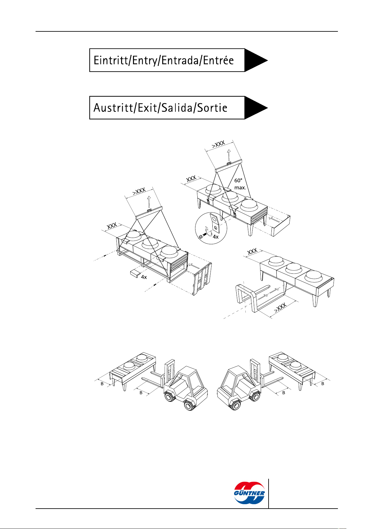
6.2 Transportation and storage
Read and observe all transport signs on the units' packaging!
Prolonged mechanical stresses caused by uneven road surfaces and potholes and vibrations
during transport by ship can cause transportation damage. Before transportation by sea or in
countries with difficult transport routes, attachment parts that are likely to vibrate – in particular
fans and base stands – must be removed for transportation.
NOTICE
GFH | 2010-09
The units are transported as complete system components. Ensure the correct hooking points
when transporting with a crane:
© Güntner AG & Co. KG
Page 31

page 31 / 59
•
Transporting the unit at the set-up point
•
Unloading the unit
21 - Transport regulation in acc. with SP 11
4 - Usage area for forklifts in acc. with SP 34
GFH | 2010-09
© Güntner AG & Co. KG
Page 32

•
Transport and unload the packed unit with suitable transport equipment (e.g. forklift, crane) at
the set-up point.
CAUTION: When transporting with a forklift: Only lift the packed unit with a forklift with full fork
length.
6.3 Storage before installation
page 32 / 59
NOTICE
Danger of corrosion and dirt build-up!
Moisture and dirt must be prevented from entering the unit.
Protect the unit against dust, dirt, moisture and wetness, damage and other harmful effects.
Harmful effects: see Safety instructions for set-up and start-up, page 33
Do not store the unit for longer than necessary. Only store the units in their original packaging
until installation. Always only place packaging units of the same size on top of one another.
Store the unit at a protected place free of dust, dirt, moisture and damage-free until its set-up
(well-ventilated halls or roofed storage site).
If the unit set-up is delayed with regard to the planned installation time: protect the unit against
weather and other harmful effects and dirt and other contaminants with an appropriate cover.
The unit must also be well-ventilated here.
GFH | 2010-09
© Güntner AG & Co. KG
Page 33

7 Set-up and start-up
7.1 Safety
7.1.1 Safety instructions for set-up and start-up
WARNING
Danger of injuries and damage to property with escaping brine!
Incorrect installation causes the danger of working fluid escaping when the unit is operated and
injuries or damage to property (see Residual hazards with the brine glycol, page 20).
Follow the set-up instructions in this chapter precisely and apply extreme care!
NOTICE
Damage to the system's cooling equipment!
Foreign materials and contaminants in the working fluid circuit can impair the effectiveness or
damage components. Particularly harmful contaminants are:
page 33 / 59
– Moisture
– Atmospheric air
– Welding and soldering residues
– Rust
– Soot/ash/cinders
– Metal cuttings
– Dust and dirt of all kinds
Moisture in the working fluid-carrying components of the unit can have the following consequences:
– Acidification
– Ageing and brine decay
– Corrosion
Atmospheric air and other non-condensable gases can have the following consequences:
– Brine/ oxidation
– Brine/ chemical reactions
Brine/ chemical reactions with the absence of moisture or atmospheric air with ageing and decay
can have the following consequences:
– Formation of organic and inorganic acids
– Corrosion
Other contaminants can cause:
– Accelerated chemical processes (decomposition)
– Mechanical and electrical faults in the brine circuit/
Ensure with installation (connecting the working fluid-carrying components of the unit to the
working fluid-carrying system of the installation's – or to the refrigeration system's heat carrier
circuit) that internal contamination is strictly avoided.
GFH | 2010-09
© Güntner AG & Co. KG
Page 34

page 34 / 59
Perform the installation with extreme cleanliness.
Finish all on-site pipe installation work before releasing the transport pressure!
Only release the transport pressure on the Schrader valve immediately before installation.
Only remove the sealing caps on the distribution and header pipe immediately before installation.
NOTICE
Danger of corrosion and dirt build-up!
Humidity and dirt may not get into the unit's interior. If humidity or dirt get into the unit's interior,
fittings and other components of the refrigeration installation can be damaged.
Protect the unit against dust, contamination, moisture and wetness, damage and other harmful influences. Harmful influences are, for example:
– Mechanical: Damages caused by impacts, objects falling on or against, collisions with trans-
port equipment, etc.
– Physical: Damages caused by close by concentrated flammable gases
– Chemical: Damages caused by contaminated atmospheres (salt, acid, chlorine, sulphur-con-
taining, or similar)
– Thermal: Damages caused by close by heat sources
Start as soon as possible with installation.
The electrical installation must only be performed by electricians in compliance with the relevant
VDE rules (or applicable national and international regulations) and the TCCs of the EPCs!
7.1.2 System-side safety requirements
The unit is a component of the brine circuit/of an installation and can only be operated in conjunction with the installation
•
All equipment required for operating the unit must be integrated into the switching and activation
equipment :
– Electrics: Fans
– Working fluids: valves and fittings
•
An emergency STOP switch that can be actuated without danger must be installed.
•
The brine-side and electrical connections for the unit must be available for the unit on the brine
circuit of the refrigeration system. The connections must be specified in the order-related offer
documents.
•
The power supply of the fans must be provided in acc. with the specifications on the type plate
on the fan motors.
•
A switch-off device for preventing unexpected start-up (repairs switch), which separates all active conductors from the power supply (all-pole switch-off), must be provided for the fans in acc.
with EN 60204-1.
•
The fans' switch-on/off device must be secured (e.g. with a padlock) to prevent uncontrolled fan
start-up.
•
The electrical motor, repairs switch, terminal box and switching cabinet connections must be
provided in acc. with the respective connection diagrams.
•
It must be possible to shut off the unit if a leak occurs.
WARNING
GFH | 2010-09
© Güntner AG & Co. KG
Page 35

•
People wearing ambient air-independent breathing apparatus in full protective clothing must also be able to activate all safety-relevant shut-off fittings.
•
It must be possible to activate all devices meant for diverting escaping working fluids from a
safe position.
7.1.3 Customer-side safety precautions
Danger of injuries!
The unit contains brine/ (see Residual hazards with the brine glycol, page 20).
The unit is operated as standard with the brine/, ethylene glycol (synonyms:
ethane-1,2-diol, glycol). Prior agreement with the manufacturer is imperative
when using other brines.
Ethylene glycol is a colourless, slightly viscous, not very fluid, water-mixable,
deliquescent liquid with a sweet smell or taste.
With skin contact ethylene glycol causes slight irritation with the danger of skin
absorption; with eye contact mucous membrane irritation; with ingestion agitation with disruption of the central nervous system; with prolonged endangering
effect – fatigue, coordination disruption, unconsciousness, kidney damage.
Ignition and fire hazard! Ethylene glycol is flammable and explosive at higher
temperatures in a vapour/gaseous state. Keep ethylene glycol away from ignition sources. No smoking!
Ethylene glycol vapours are heavier than air and may flow off to rooms on a lower level. In still air there may be an increase of the ground level concentration.
With high concentrations, there is a danger of suffocation due to reduced oxygen concentration, especially at ground level.
Avoid contact with skin, eyes and clothing! Remove contaminated, soaked
clothing immediately!
There is no imminent danger for the staff. Ethylene glycol vapours are heavier than air and may flow off to rooms on a lower level. In still air there may be
an increase of the ground level concentration. With high concentrations, there
is a danger of suffocation due to reduced oxygen concentration, especially at
ground level.
Do not bring into contact with heavy oxidation agents (chromo-sulphuric acid,
potassium permanganate, smoking sulphuric acid, or similar)! Danger of strong
reactions!
Unauthorised people must not have access to the unit. When setting the unit up
it must be ensured that the coolant escaping from the unit cannot penetrate the
interior of the building or put people at risk in any other way.
page 35 / 59
WARNING
GFH | 2010-09
WARNING
Danger of environmental pollution!
•
Set up the unit so that brine/, which can escape from the unit in the event of a fault, cannot en-
ter water systems or sewage.
•
Operate the facility for recovering or disposing of brine/ so that the danger of a brine emission
into the environment is kept as low as possible.
© Güntner AG & Co. KG
Page 36

7.2 Requirements at the set-up point
You will find the dimensions and weights in the order-related offer documents.
Ensure that the unit is set up so that it is not damaged by environment-conditional hazard
sources (production, transport and other processes at the set-up point) and its functioning is not
disturbed by the interventions of unauthorised persons.
Position the unit so that it cannot be damaged by internal traffic or transport processes.
Enable optimum unit control and accessibility:
– Place the unit so that is can be monitored and controlled from all sides at all times.
– Ensure that sufficient space is provided for maintenance.
– Ensure that all liquid-carrying components, connections and lines and all electrical connec-
tions and lines are easy to access.
– Ensure that the pipes' identification is well visible.
Lightning antennae beside the unit are recommended as lightning protection.
Several units can be placed space-saving in rows with high nominal capacity to cover high capacities. With double or multiple row set-ups a substructure is required to guarantee sufficient
air-side pressurizing.
page 36 / 59
NOTICE
GFH | 2010-09
© Güntner AG & Co. KG
Page 37

Outdoor set-up
page 37 / 59
1 Airflow direction
2 Head space required
Unit dimensions: L = length, W = width, H = free flow height
Heat exchanger free flow area: AA = L * W (in m2)
Heat exchanger afflux area: AZ = 2(L+W) * H (in m2)
Condition: AZ ≥ AA * 0.7
GFH | 2010-09
© Güntner AG & Co. KG
Page 38

Set-up next to a building wall
1 Airflow direction
2 Free area for air suction
page 38 / 59
Unit standing lengthways alongside the building wall.
Legs must be extended, from serial length to customized length
400 mm to 800 mm
600 mm to 1000 mm
Set-up in a pit/hollow
1 Airflow direction
2 Free area for air suction
Fans without additional device (without Güntner Streamer)
X ≥ 0.7 * W
Fans with Güntner Streamer
X ≥ 0.5 * W
Min. spacing X on both long sides
GFH | 2010-09
© Güntner AG & Co. KG
Page 39

1 Airflow direction
2 Free area for air suction
Fans with Güntner Streamer
(floor level is Streamer top edge)
X ≥ 0.6 * W
Min. spacing X on both long sides
page 39 / 59
1 Airflow direction
2 Free area for air suction
Fans with ventilation channel and rectifier
X ≥ 0.5 * W
LD = 450 bis 650 mm
H1 = 200 to 340 mm (depending on fan diameter)
Min. spacing X on both long sides
GFH | 2010-09
© Güntner AG & Co. KG
Page 40

Setting up several units
page 40 / 59
1 Airflow direction
2 Free area for air suction
Recommended set-up
Minimum clearance B1 = 80 mm (necessary because of projection on vibration
dampers):
Free flow area: AA = L * W * n (in m2) n... Number of units
Afflux area: AZ = 2 * L * H + 2 * n * B * H (in m2)
H results from the condition: AZ ≥ AA * 0.7 (in m2)
H = f (n; L, W)
GFH | 2010-09
© Güntner AG & Co. KG
Page 41
7.3 Unpacking the unit
page 41 / 59
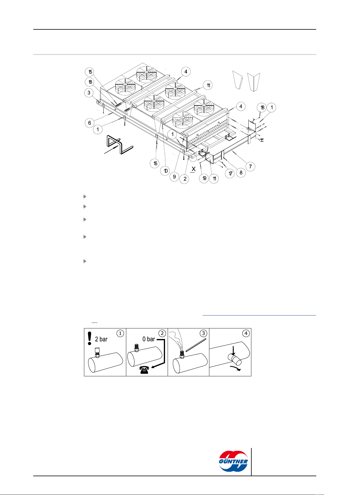
Remove lateral lining boards, squared timber and packaging material (1, 7, 8,11 etc.).
Remove lining boards, squared timber (1, 2, 3, 4, 5, 8, 9, 10, 11).
Check delivery scope on completeness. For complete delivery scope, refer to the order-specific
offer documents.
Note damage due to transport and / or missing parts on the delivery note. Report damage or
missing parts immediately to the manufacturer in writing. Damaged fins can be straightened with
a fin comb on site.
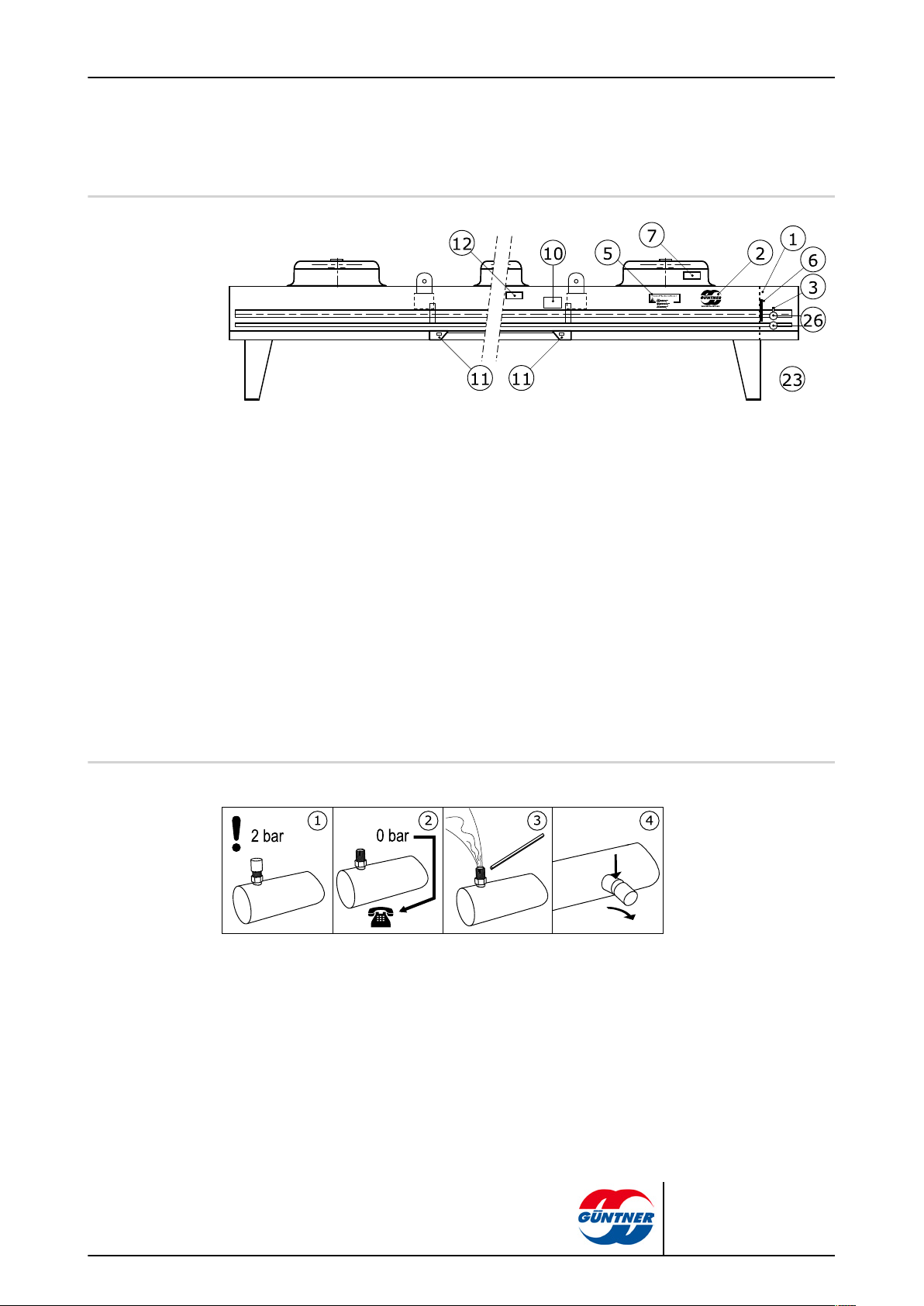
Check transport excess pressure: The units are delivered by the manufacturer with approx. 1
bar transport excess pressure (cleaned and dried air). Check transport pressure at the Schrader
valve (presure measurement). For pressure-less unit: Report immediately to manufacturer and
note missing pressure on delivery note. Ein druckloses Gerät deutet auf eine Undichtigkeit am
Gerät hin.
WARNING! Danger of injuries and damage to property due to escaping convector fluid! A
presure-less unit is sign of a leak on the unit due to transport damage. Escaping convector fluid due to leaks on the unit can lead to injuries ( see Residual hazards with the brine glycol, page
20).Do not take the unit into operation!
GFH | 2010-09
1 Transport pressure filling
2 Check transport pressure; inform manufacturer with unpressurised unit
3 Release transport pressure
4 Remove blanking plugs.
© Güntner AG & Co. KG
Page 42

NOTICE
Danger of corrosion and dirt build-up!
Moisture and dirt must be prevented from entering the unit.
Protect the unit against dust, dirt, moisture, wet conditions, damaging and other detrimental influences. Detrimental influences:see Safety instructions for set-up and start-up, page 33
Begin with the installation as soon as possible.
7.4 Installation
7.4.1 System-side requirements for stress-free installation
Prevent stresses in the unit:
°
Ensure that all fixing points have the same spacing to the fixing level.
°
Ensure that all fixing points maintain the same spacing to the fixing level under load and permanently.
Set up and fix units as follows: Airflow must not be impaired by obstructions.
page 42 / 59
The units must be installed on fixing points that are appropriate for the unit's weight and then
bolted with fixing bolts. The operator or installer of the equipment is responsible for ensuring
that the bolted connections are of an adequate strength. The following instructions must be observed when fixing the units:
– The diameter of the mounting holes have been statically determined by the manufactur-
er; the fixing bolts must be adapted accordingly. When calculating the transferring bearing
strength it is imperative to take into account the total weight of the unit (= structural weight +
weight of pipe content + additional weight, such as water, frost, ice, dirt or similar).
– The fixing bolts must be secured against loosening with an appropriate locking device.
– The fixing bolts must not be overtightened or stripped.
– All fixing bolts must be tightened equally.
Prevent the unit from shifting in its position. Fix the unit in its position. Tighten the fixing bolts
and secure then against loosening.
Only fix the unit to the intended fixing points.
7.4.2 Mounting the unit
Danger of injuries with escaping brine/!
In case of improper installation, leak of working fluid can occur during operation of the installation, this can lead to injuries or damage to property (see Residual hazards with the brine glycol,
page 20)
WARNING
GFH | 2010-09
© Güntner AG & Co. KG
Page 43
7.5 Notes on connecting the unit
Danger of injuries and damage to property caused by escaping brine/!
In case of improper installation, leak of working fluid can occur during operation of the installation, this can lead to injuries or damage to property (see Residual hazards with the brine glycol,
page 20).
Prevent working fluid from escaping from the unit into the environment.
•
Secure all working fluid-carrying lines against mechanical damage.
•
In areas that are used for internal traffic, only lay the pipelines to and from the unit with con-
nections and fittings that cannot be removed.
Ensure that the on-site connections do not exercise any forces upon the distribution and header
points. This can cause leaks on the working fluid connection points of the unit and on connection
points of the on-site pipe-laying.
Ensure that:
•
Release devices to prevent liquid escapes are provided and available.
page 43 / 59
WARNING
7.5.1 Operation with water spray system
Limited water spraying is recommended for reducing peak capacity levels. The following must be
observed when using a water spraying system with unknown water quality:
•
Operation with water spraying max. 50 hours/year.
•
Soft water (≤4°dH); use softening system where required.
•
Water spraying with max. 3 bar.
•
Pipe system with nozzles can be provided.
NOTICE
High corrosion danger (high voltage potential, Cu/Al) if inadmissible water quality is used!
Only use water in admissible quality!
NOTICE
Observe the VDMA leaflet "Notes and recommendations for operating and maintaining evaporation cooling plants" (name translated).
7.5.2 Connect the unit to the heat carrier circuit of the system
WARNING
GFH | 2010-09
Danger of injuries and damage to property!
Improper connection to the heat carrier circuit of the system causes hazards:
•
Welding work on pressurised parts can result in fires or explosions.
•
Leaks result in escaping brine/ (see Residual hazards with the brine glycol, page 20).
•
Soldering and welding work on pressurised parts can result in fires or explosions.
•
Smoking or open light can cause fires or explosions.
© Güntner AG & Co. KG
Page 44
page 44 / 59
•
Ensure that stresses and vibrations from the system including the heat carrier circuit are not
passed on to the unit.
•
Only lay working fluid-side connections stress-free! The on-site pipeline system must be
braced before connecting to the unit!
•
Soldering and welding work is only permitted on unpressurised units!
•
Evacuate the unit professionally in acc. with EN 378-2.
•
The use of open fire at the installation site is forbidden. Fire extinguishers and extinguishing
agents used to protect the equipment and the operating staff must comply with the require-
ments of EN 378-3.
Install the pipes in acc. with EN 378-1 and EN 378-3. Ensure here:
– Release devices to prevent liquid escapes must be provided and available.
– That the pipeline installation is kept as short as possible. Use as few bends as possible, and if
bends are necessary, use big radii!
– The free space around the unit must be big enough to ensure there is no danger to the unit; reg-
ular maintenance of the components must be possible, and it must also be possible to check
and repair components, pipes and fittings.
– It must be possible to shut off the unit if a leak occurs. It must be possible to activate all devices
used for diverting escaping working fluids from a safe position.
– Electrical components, e.g. for fan operation, for ventilation, for illumination and for alarm sys-
tem on installation site, have to be designed with regard to condensation of air humidity and
droplet formation in acc. with EN 378-3; section 6.
– Observe the following when soldering:
°
All connections must be hard-soldered!
°
Avoid percussive soldering joints; use copper pipe ends that are widened on one side (capillary soldering)!
°
Prevent leaks, solder precisely and carefully!
°
Prevent overheating when soldering (danger of excessive scaling)!
°
Use shielding gas when soldering (prevent excessive scaling)!
After completing pipe installation and before connecting the units they must be professionally
cleaned internally and evacuated in acc. with EN 378-2.
7.5.3 Unit electrical connection and protection
All fans with rotating current drive can be operated via D-S switch-over with two different speeds:
•
D: high speed
•
S: lower speed
The fans can be speed-controlled with the use of Güntner control units.
Connect fan motors in acc. with motor connection circuit and check connection.
Provide power supply in acc. with the specifications on the fan motor's type plate:
■
The fan motors are operated in 1~ alternating current and 3~ rotating current (IP 54).
Connect thermo contacts for motor protection.
Seal all electrical lines to the connection boxes in acc. with their protection class. The connection class is specified in the order-related offer documents.
NOTE! Danger of damaging! If the fusing is too high there is the danger of injuries to people
and damage to property. The supply lines must always be fused in acc. with the smallest wire
cross-section.
GFH | 2010-09
© Güntner AG & Co. KG
Page 45

7.6 Perform acceptance test
Danger of injuries and damage to property!
Escaping brine/ can cause injuries or even death (see Residual hazards with the brine glycol,
page 20).
Perform the following acceptance test with an expert before starting up the unit after making important changes and after a unit swap-out.
Ensure that the temperature at the set-up point corresponds with the technical data (see Techni-
cal data, page 26).
Ensure that sufficient air can be sucked in and released.
Ensure that the supply feed is sufficient for the required energy. Compare the unit inside the
brine circuit of the systemwith the plans of the systemincluding the brine circuit and the electrical
wiring diagrams.
Test the unit for vibrations and movements that can be caused by the fans and operation of the
system including the brine circuit . Remove oscillations, vibrations and movements following
consultation with the manufacturer or independently.
Perform visual inspection of the structural design, the brackets and fixtures (materials, sequence, connections), the ability to operate and the arrangement of the fittings.
Check and re-tighten all threaded connections, especially on the fans.
page 45 / 59
WARNING
Check installation of pipe connections.
Check laying of working fluid-carrying connection pipes.
Ensure that the unit is protected against mechanical damage.
Ensure that the unit is protected against inadmissible heating up and cooling down.
Check the fin blades protection.
Ensure that optimum unit control and accessibility are guaranteed.
– Is the unit placed so that it can be monitored and controlled from all sides at all times?
– Is sufficient space provided for maintenance?
– Are all liquid-carrying components, connections and lines and all electrical connections and
lines easy to access?
– Are the pipes easy to identify?
Check heat exchanger surfaces for dirt and clean as required (see Clean unit, page 55).
Perform function tests on the fans (rotation direction, power consumption, etc.).
Check electrical connections of the fan motors for damage.
Check the soldering and welding connections, the electrical connections and the fixture connections.
Perform pressure test with test gas and with a test pressure of 1.1-times the permissible operating pressure: check the connection seals and detect leaks, e.g. with foaming agent, or similar.
Check corrosion protection: Perform a visual inspection on all bends, components and component holders that are not heat-insulated. Document and archive test results.
Perform test run. Observe and check unit during test run, in particular for:
GFH | 2010-09
– Fan smooth running (bearing noises, contact noises, imbalances, etc.).
– Fan power consumption:
© Güntner AG & Co. KG
Page 46

– Leaks
Report all defects to the manufacturer immediately. Remove defects following consultation with
the manufacturer.
Check the unit and the unit's interaction with the brine circuit of the system again after 48 operating hours, especially on the connections and on the fans, and document the test results.
7.7 Test readiness for operation
Ensure that all electrical protective measures are ready to function.
Ensure that all working fluid-carrying connections are securely in place.
Ensure that all electrical connections (fans ) are effected securely.
7.8 Putting the unit into operation for the first time
WARNING
Danger of injuries and damage to property!
page 46 / 59
Escaping heat carrier/ can cause injuries or even death (see Residual hazards with the brine gly-
col, page 20).
Only put the unit into operation, when:
•
the units has been properly mounted and connected (see Installation, page 42),
•
You have performed a complete acceptance test (see Perform acceptance test, page 45).
•
You have performed a test for ensuring the system's readiness for operation (see Test readi-
ness for operation, page 46) and
•
all safety precautions (see Safety, page 33) have been taken.
Follow the operating instructions manual of the system!
Contact the manufacturer immediately if you want to operate the unit under different operating
conditions as those defined in the order-related offer documents.
Switch on the system including the heat carrier circuit and of the electrical system (see system).
Activate the unit:
– Open the valves on the inlet and outlet-side heat carrier circuit of the system.
– Activate fans
Wait until the operating point is reached. After the operating point is reach the unit is ready to
operate (see system).
Parameters for setting the operating point, see order-related offer documents. Operating point:
•
Heat carrier flow temperature
•
Heat carrier return temperature or circulating heat carrier volume
•
Airflow volume
•
Air inlet temperature
To ensure the specified operating point is complied with the actuators for the operating point setting
must be secured against unauthorized access (e.g. by sealing, screwing on caps, removing hand
wheels, etc.).
GFH | 2010-09
© Güntner AG & Co. KG
Page 47

8 Operation
8.1 Safety
Danger of cutting off, pulling in!
Burn hazard!
page 47 / 59
WARNING
There is a danger of cutting off fingers on the rotating fan blades, injury hazard
for the hands and pulling in danger with loose elements such as hair, necklaces
or clothing parts.
Do not operate fans without guard grille!
WARNING
Danger of burns if parts are touched (see Thermal residual hazards, page 20).
Do not touch any parts of the unit without protective gloves when the unit is in
operation or if it has not yet cooled down again after operation.
8.2 Putting the unit into operation
To operate the unit, the system must be in operation, including the brine circuit and the electrical
system. The unit must be started up by opening the respective valves on the inlet and outlet-side
of the brine circuit and by connecting to the electrical system (see refrigeration system operating instructions manual):
Switch on electrical system
Open working fluid-carrying lines
Switch on fans
8.3 Taking the unit out of operation
GFH | 2010-09
The units are system components of a refrigeration system, including the brine circuit. The unit is
taken out of operation by switching off the brine circuit of the system in acc. with the system operating instructions manual. To do this, the working fluid-carrying lines must be shut off from the system
and the fans must be disconnected from the electrical system (see refrigeration system operating
instructions manual):
© Güntner AG & Co. KG
Page 48

Switch fans off
Switch electrical system off
Close working fluid-carrying lines
NOTE! When shut down consider max. operating pressure! If necessary, take precautions so
that it cannot be exceeded.
With shutdown times of a month or longer put the fans into operation for approx. 2-4 hours a
month to maintain their functionality.
8.4 Shutting the unit down
Danger of injuries and damage to property!
Escaping brine/ can cause injuries (see Residual hazards with the brine glycol, page 20, and see
Residual hazards caused by pressurised parts, page 22).
page 48 / 59
NOTICE
WARNING
Ensure that the maximum operating pressure is not exceeded after the shutdown either!
NOTICE
Danger of corrosion and dirt build-up!
Moisture and dirt must be prevented from entering the unit.
Protect the unit against dust, dirt, moisture, wet conditions, damaging and other detrimental influences (see Safety instructions for set-up and start-up, page 33).
With shutdown times of a month or longer put the fans into operation for approx. 2-4 hours a
month to maintain their functionality.
Take the unit out of operation (see Taking the unit out of operation, page 47).
Secure the unit:
– When shutdown consider max. operating pressure (see Technical data, page 26)! If neces-
sary, take precautions so that it cannot be exceeded.
– Secure the fan motor drives against switching on again
– Secure working fluid-carrying lines against pressurizing with working fluid.
– Secure unit against detrimental influences at the installation or storage location (see Safe-
ty instructions for set-up and start-up, page 33) in order to keep all unit components in good
state for proper use and to conserve the usability of the unit. For this purpose, special stor-
age conditions (see Storage before installation, page 32) and preventive measures for corro-
sion protection have to be provided, regular testing of the functionality of the fans and of the
unit taken out of operation have to be effected.
Drain the unit: Completely release brine/ (see Residual hazards with disposal, page 25).
GFH | 2010-09
© Güntner AG & Co. KG
Page 49
8.5 Putting the unit into operation after a shutdown
The unit must be put back into operation after a shutdown in acc. with the system-specific set-up in
acc. with the operating instructions manual as follows:
Test the unit's readiness for operation (see Test readiness for operation, page 46). Perform
pressure test and visual inspection for corrosion protection.
NOTE! The pressure test with recommissioning must only be carried out with appropriate media at appropriate test pressure.
Put the unit into operation (see Putting the unit into operation, page 47).
8.6 Changing the unit over to another working fluid
WARNING
Danger of injuries and damage to property!
Considerable dangers can be caused with operation with another working fluid without prior manufacturer approval (Improper use).
page 49 / 59
The unit must not be changed over to another working fluid without prior written consent by
Güntner AG & Co. KG.
Ensure that the unit manufacturer has agreed to the changeover.
Ensure that the right working fluid is re-filled. Ensure that all materials used in the unit are compatible with the new working fluid.
Ensure that the permissible pressure is not exceeded.
Check that the new working fluid can be used without requiring a new test certificate for the unit.
Ensure that classification is complied with.
The safety device for the unit must be swapped out or reset.
Mixtures with residues of working fluid , for example, must be prevented.
All information concerning the new working fluid must be changed accordingly.
The complete documentation, including these operating instructions and the system operating
instructions manual must be changed accordingly.
Perform acceptance test (see Perform acceptance test, page 45).
GFH | 2010-09
© Güntner AG & Co. KG
Page 50

9 Troubleshooting
9.1 Safety
Danger of injuries and damage to property!
Faults that are not described in these operating instructions must only be removed by Güntner.
Contact the Güntner hotline.
Faults that are described in these operating instructions must only be removed by appropriately
trained personnel (see Personnel, care requirements, page 16).
With faults that occur during the operation, monitoring and maintenance of the complete system,
inform Güntner AG & Co. KG immediately.
9.2 Service
Office hours
page 50 / 59
WARNING
Tel. +49 8141 242-473
Fax. +49 8141 242-422
Email: service@guentner.de
Mon-Thurs: 7.30 am - 5 pm
Fri: 7.30 am - 1.30 pm
9.3 Troubleshooting table
Fault Possible cause(s) Remedy
Power supply interrupted Restore power supplyFan motor not
running
Bearing noises Defective fan motor Renew bearing or fan motor
Unit capacity
not achieved
Fan blade stuck Enable fan to rotate freely
Defective fan blades Change fan bladesUnit vibrating
Loose fan fixture Tighten fixtures
Coil is strongly contaminated with
dirt
Fans not running properly or down Repair, swap out fans
Working fluid pressurising defective
(temperature and quantity insufficient)
Clean
Set working fluid pressurising values (temperature and quantity) to
reference values.
GFH | 2010-09
Unit capacity
not achieved
Working fluid
escaping
Insufficient heat exchanger setting Set heat exchanger setting (con-
centration, inhibition)
Unit working fluid-carrying components leaking
Switch off working fluid feed and
fans, close leak
© Güntner AG & Co. KG
Page 51

10 Maintenance
10.1 Safety
10.1.1 Before starting all maintenance
Danger of injuries and damage to property with escaping working fluid (see Residual hazards with
the brine glycol, page 20)!
Only perform maintenance work – especially welding work – on the leaking unit after completely
removing the working fluid from the leaking unit!
Perform the following safety measures before beginning all maintenance work:
■
Evacuate the unit's heat exchanger
■
Clean and blow out the unit's heat exchanger.
10.1.2 With all maintenance work
page 51 / 59
WARNING
WARNING
Danger of injuries and damage to property with escaping working fluid! see Residual hazards
with the brine glycol)!
Escaping working fluid with leaks on the unit can cause the following hazard situations and injuries:
Warns against hot surfaces!
In operation the unit's heat exchanger and pipes have temperatures of over +45
°C. Contact can cause burns.
With brine temperatures over +45 °C there is the hazard of burns on pipe components and distribution pipes. Use hand protection!
Warns against frostbite!
With insufficient frost protection filling and operation in areas with frost hazard
the unit can cause frostbite. With units that cannot be drained completely the
GFH | 2010-09
© Güntner AG & Co. KG
Page 52

page 52 / 59
hazard of frostbite also remains after draining. It is imperative that the proper
ventilation be ensured when draining the unit. With pressure test, operation and
shutdown of units filled with water or insufficient frost protection filling or insufficient setting of the brine, these are disrupted at minus temperatures.
•
Use eye protection!
•
Use hand protection!
•
Ensure that the unit in question is pressure-free before maintenance work begins or the working fluid is sucked up from the unit in question.
•
Power off the electrical system and secure it against unintentional switching on again.
•
Separate the unit to be maintained from the brine circuit of the system and secure it.
Danger of damage to property!
With work in the inlet and outlet feeds of the fans and heat exchanger, objects
can get into the fans and therefore cause faults and damage on the components.
•
Power off the fans before beginning maintenance work and secure them
against switching on again.
•
After the work has finished do not allow any objects to get back into the inlet
and outlet feeds of the fans or the set-up room.
Only step on to the units when required and only with firm, tough and safe footwear.
If the units do not have any railings, always only walk on them when required and with a safety
device that prevents falling.
10.1.3 After all maintenance work
NOTICE
WARNING
WARNING
GFH | 2010-09
Danger of injuries and damage to property caused by escaping brine/ (see Residual hazards with
the brine glycol, page 20)!
Perform the following safety measures after finishing all maintenance work:
•
Ensure the switching and activation devices, the measuring and display devices and the safety devices function properly.
•
Ensure the working fluid fittings are functioning.
•
Check the identification of the pipelines and ensure this is visible and legible.
© Güntner AG & Co. KG
Page 53

•
Check the fixing and corrosion protection of the components in question.
•
Ensure the electrical connections (fans) are functioning.
•
Perform a pressure test and a tightness test (see operating instructions manual annex).
•
Perform an acceptance test (see Perform acceptance test, page 45).
•
Perform a pressure test (see operating instructions manual annex).
10.2 Inspection and maintenance plan
10.2.1 Fans
The checks to be performed are listed in the following sections as time-scaled checklists.
The manufacturer's operating specifications take priority for this component. Güntner AG & Co KG
recommends proceeding in acc. with the following inspection and maintenance plan:
d = daily, w = weekly, m = monthly, y = yearly
Work to be performed d w m y
page 53 / 59
Check the fans for dirt build-ups.
•
With dirt build-ups: Clean fans (see Clean unit, page 55)
Check the fan drive for smooth running.
•
Vibrations on the unit: remove imbalances
•
Where required, tighten and correct blade fixtures and blade settings
Fan bearing: Running sound and smoothness changes
•
Swap out bearing
Fan motor: Is a new bearing due?
•
Swap out bearing or motor; where applicable, clean and repair
motor
Fan wheel: corrosion on bolts (with threaded blades)
•
Swap out bolts
Fan blades: Corrosion or damage on blades
•
Swap out blades or wheel
*) Recommended: every six months
10.2.2 Unit heat exchanger
X
X
X
X
*
X
*
X
*
GFH | 2010-09
WARNING
Danger of injuries and damage to property caused by escaping brine(see Residual hazards with
the brine glycol, page 20)!
d = daily, w = weekly, m = monthly, y = yearly
Work to be performed d w m y
Check heat exchanger for dirt build-ups.
•
With dirt build-ups: Clean heat exchanger (see Clean unit, page
55).
X
© Güntner AG & Co. KG
Page 54

page 54 / 59
d = daily, w = weekly, m = monthly, y = yearly
Work to be performed d w m y
Check heat exchanger's general condition.
•
Damages found: remove damages
Check heat exchanger's operating point (see Operation, page 47).
•
Change in fan capacity found: restore required system-side conditions (including brine circuit).
•
Change in surface temperatures found: restore required system-side conditions (including brine circuit).
Change in heat exchanger setting found: restore required heat exchanger setting (concentration, inhibition)
Check heat exchanger and connections for tightness.
•
Repair affected unit part (see Remove leaks, page 55).
Check heat exchanger for working fluid pressurising.
•
Restore required brine-side conditions.
Check heat exchanger for corrosion.
•
Corrosion or damage on core tubes, fins, support structures, tube
connections, fixtures: repair unit sections affected.
*) recommended: every six months
Care and maintenance plan
X
X
X
*
X
*
X
X
*
Measure Cleaning agent Interval
Component cleaning Mechanically As required (visual inspec-
tion)
Complete cleaning Warm water or environmen-
tally safe cleaning agent
Leak check After 6 months
Heat exchanger setting
check
Corrosion protection check After 6 months
After 120 hours
After 6 months
GFH | 2010-09
© Güntner AG & Co. KG
Page 55
10.3 Maintenance work
10.3.1 Remove leaks
Danger of injuries with brine (see Residual hazards with the brine glycol, page 20)!
•
Have leaks removed as quickly as possible by an expert.
•
Do not fill with a working fluid other than that specified in acc. with the order-related offer documents!
•
Only put the unit back into operation when all leaks have been repaired.
Perform all work including pressure, acceptance and functional test (see Perform acceptance
test, page 45, and see Test readiness for operation, page 46).
10.4 Clean unit
10.4.1 General
The following applies for cleaning: The operator must ensure that the cleaning agent is environmental friendly. Harmful to the environment substances, e.g. acid-forming, are forbidden.
page 55 / 59
WARNING
Clean casing by rinsing with warm water (approx. +25°C) and/or with environmentally friendly
cleaning agents.
Rinse thoroughly with water after using cleaning agents.
Allow casing to dry completely.
Check working fluid-carrying and electrical connections (see Test readiness for operation, page
46).
10.4.2 Clean heat exchanger
Drain the unit (see system).
Shut off the unit (see system).
Power off the fans (see system).
Perform defrosting (see system).
Clean the heat exchanger with one of the following procedures:
– Cleaning with compressed air (see Cleaning with compressed air, page 56).
– Hydraulic cleaning (see Hydraulic cleaning, page 56)
– Cleaning with brushes or brushes and compressed air (see Cleaning with brushes or brush-
es and compressed air, page 57).
NOTICE
GFH | 2010-09
Danger of damage to property!
The fins can be damaged with too high a pressure, too small a distance or a cleaning jet that hits
the fins at an angle. Mechanical cleaning with hard objects (e.g. steel brushes, screw drivers, or
similar) damages the heat exchanger.
© Güntner AG & Co. KG
Page 56

•
Use a pressure of max. 50 bar with hydraulic cleaning and max. 80 bar with cleaning with compressed air!
•
Maintain a minimum distance from the fins of 200 mm!
•
Always aim the jet vertically (max. ±5 degree deviation) at the fins!
•
Do not use any hard objects when cleaning!
Switch fans on (see system).
Open drain side (see system operating instructions manual).
Open inlet side (see system operating instructions manual).
10.4.2.1 Cleaning with compressed air
Blast heat exchanger (max. 80 bar pressure) with compressed air to remove dirt and contaminants.
NOTE! Hold the jet of the cleaner vertical to the fins (max. deviation of ±5 degrees) to prevent
fins from bending.
10.4.2.2 Hydraulic cleaning
page 56 / 59
WARNING
Warns against dangerous electrical voltage!
Direct and indirect contact with voltage-carrying parts of motors and electrical
lines can cause serious injuries or death. Water and cleaning agents conduct
electricity.
•
Power off the fans for cleaning with water or steam jet and ensure them
against switching on again.
NOTICE
Danger of damage to property!
Water or steam jets can damage fans, electrical lines or other components.
•
Ensure that electrical connections and motors, as well as components and stored goods at
the set-up point are not touched by water or steam jets. Cover these if required.
Heavier moisture or greasy dirt must be removed with a high-pressure water jet (max. 50 bar
pressure), steam pressure jet (max. 50 bar pressure), min. 200 mm distance with flat jet nozzle,
or using neutral cleaning agent where applicable, always against the airflow direction. Ensure
here:
– With oily and greasy dirt it helps to add a cleaning agent to the water.
– When applying chemical agents ensure that they are not aggressive towards the unit's mate-
rials. Rinse the unit off after the treatment.
– Cleaning should be done from inside to the outside (but always opposing the dirt onset) and
from top to bottom, so that the dirt can be removed without returning.
GFH | 2010-09
© Güntner AG & Co. KG
Page 57

page 57 / 59
– Hold the jet of the cleaner vertical to the fins (heat exchanger – max. deviation of ±5 de-
grees) to prevent fins from bending.
Continue cleaning until all dirt has been removed.
10.4.2.3 Cleaning with brushes or brushes and compressed air
Remove dry dust or dirt with a brush, a hand brush or with compressed air (max. 80 bar pressure, min. distance of 200 mm to the fins; against the airflow direction) or with a powerful industrial vacuum cleaner. Ensure here:
– Use soft brushes (no steel brushes or similar)!
– Where possible, cleaning should be from the top down. Where possible, cleaning should
be from top to bottom, so that the dirt can be removed without the possibility of returning to
cleaned parts. Continue cleaning until all dirt has been removed.
– Always brush the fins lengthways – never across!
10.4.2.4 Cleaning the pipe insides
Rinsing with solvents removes dirt build-ups formed by lime scale, paint-type layers, oil residues,
etc.
The following are suitable as solvents:
•
10%-content formic acid
•
Trichlorethylene for organic layers
Cleaning principle:
GFH | 2010-09
1 Pump
2 Heat exchanger
3 Containers for catch-
ing cleaning liquid
Chemical cleaning is applied where the dirt is stubborn or with heat exchangers with lime scaled
pipes and collectors.
© Güntner AG & Co. KG
Page 58

page 58 / 59
Select the pump's supply rate so that a speed that is adjusted to the cleaning effect is achieved
(2.5 to 5 m/s).
Neutralise and rinse the heat exchanger well after cleaning.
WARNING
Toxic hazard!
Trichlorethylene is harmful to the health and highly narcotic: inhalation of air
with 200 ppm causes tiredness. It has been classified by the MAC Commission
as carcinogenic (category 2) and germ cell mutagenic (category 3B). It must be
identified as "Toxic".
Acute poisoning causes brain damage, blindness and destruction of the smell
and taste senses.
•
Only use trichlorethylene in closed systems with complete recovery.
•
Exclude all open flames or spark sources.
•
Smoking is forbidden.
•
Protect the skin and eyes with suitable protective materials.
10.4.3 Cleaning fans
Danger of cutting off, pulling in!
There is a danger of cutting off fingers on the rotating fan blades, injury hazard for the hands and
pulling in danger for loose elements such as hair, necklaces or clothing parts.
•
Power off the unit before you begin maintenance work. Secure the unit against unintentional
switching on again by removing the electric fuses for the unit. Secure the unit with a suitable
warning sign referring to unintentional switching on.
•
Put fans and guard grilles that were removed or opened for maintenance back into their original status without fail before you put the unit back into operation!
Dirt build-ups on the fans, the streamers or air outlet connectors (if installed) and the fan guard
grilles must be removed regularly, otherwise they will cause imbalances or destruction and power
losses. The fan motors themselves are maintenance-free.
Power off the unit and secure it against unintentional switching on.
Clean fans with one of the following procedures:
NOTE! Danger of damage to property! Mechanical cleaning with hard objects (e.g. steel brushes, screw drivers, or similar) damages the fan. Forbidden!
– Cleaning with compressed air: Blow fans with compressed air (max. 10 bar pressure; min.
distance 200 mm) to remove dirt and contaminants. Continue cleaning until all dirt has been
removed.
– Cleaning with compressed air and brushes: Remove dry dust or dirt with a brush, a hand
brush or with compressed air (max. 10 bar pressure, min. distance of 200 mm) or with a
powerful industrial vacuum cleaner. Ensure here: use soft brushes (no steel brushes or simi-
lar)! Continue cleaning until all dirt has been removed.
Mount guard grille, streamer or air inlet connections (if installed)
WARNING
GFH | 2010-09
Switch unit on
© Güntner AG & Co. KG
Page 59

11 Plans/diagrams
11.1 Electrics documentation
11.1.1 Fan motor connection diagram
11.2 Working fluidconnection diagram
See motor terminal box cover inside on the fan.
See order-related offer documents
page 59 / 59
GFH | 2010-09
© Güntner AG & Co. KG
 Loading...