

Page 1
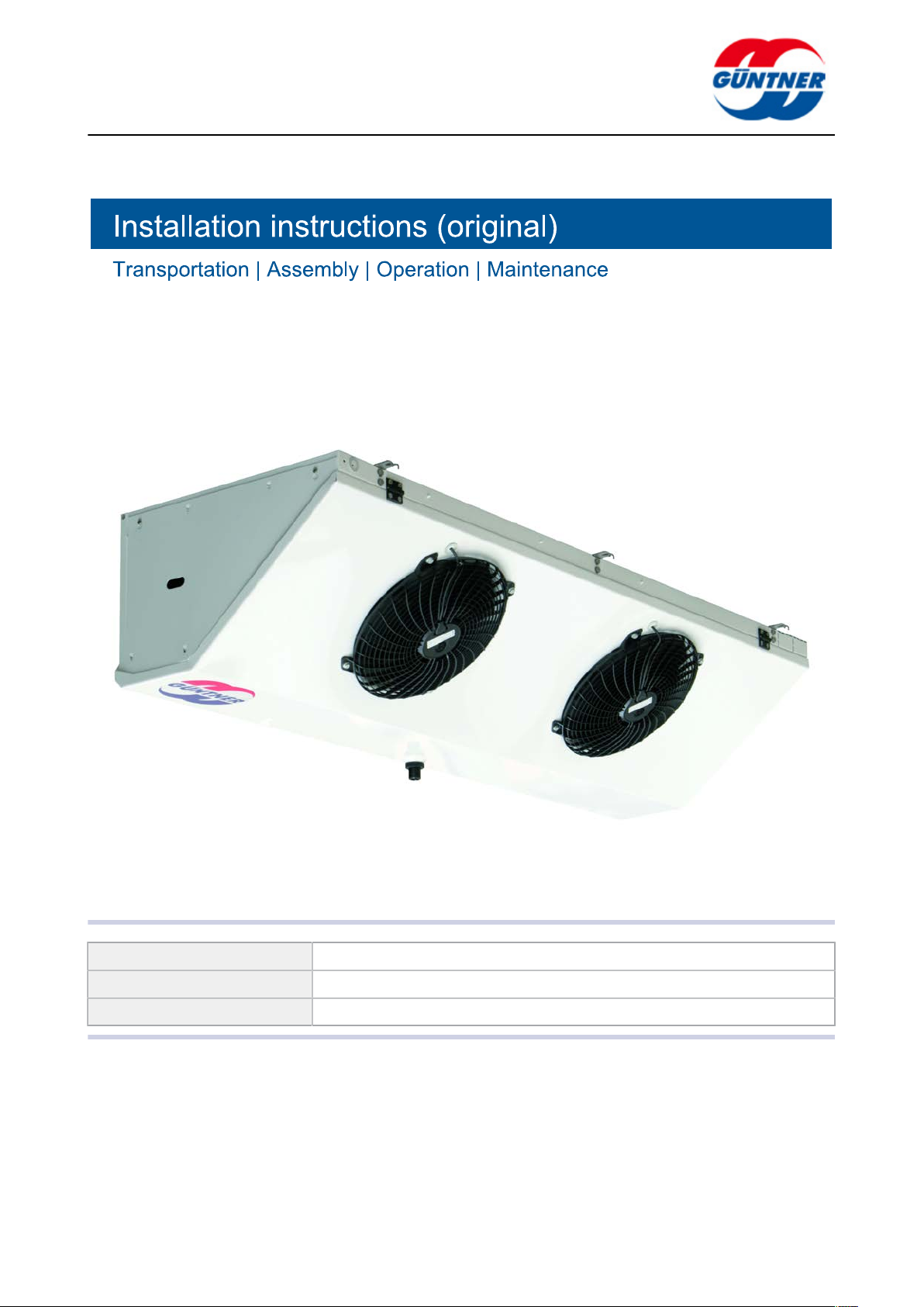
CO2-evaporators – CXGDF.1
Product line: CO2aircoolers
Series description: Slim ceiling evaporators
Series: CXGDF.1
www.guentner.de
CXGDF.1 | 2015-12
Page 2
Contents
page 2 / 68
1 Important basic information...................................................... 5
1.1 Safety instructions........................................................................... 5
1.1.1 Observing operating instructions........................................................5
1.2 Importance of the EN 378 series of standards – refrigeration
systems and heat pumps – safety-related and environmental re-
quirements.........................................................................................5
1.3 Responsibilities................................................................................ 5
1.3.1 Manufacturer's responsibilities........................................................... 5
1.3.2 Responsibilities of the system’s installer............................................6
1.3.3 Owner or operator responsibilities..................................................... 6
1.4 Legal notes........................................................................................7
1.5 Operating instructions..................................................................... 7
1.5.1 Scope..................................................................................................7
1.5.2 Set-up and other applicable documents............................................ 7
1.6 Conventions...................................................................................... 8
1.6.1 Typographical conventions.................................................................8
1.6.2 List of abbreviations........................................................................... 8
1.7 Conventions for safety signs and notices.....................................9
1.7.1 General safety signs and their meaning in these operating instruc-
tions.................................................................................................... 9
1.7.2 Warning symbols and their meaning in these operating instruc-
tions.................................................................................................... 9
1.7.3 Prohibitory signs and their meaning in these operating instruc-
tions.................................................................................................. 10
1.7.4 Mandatory signs and their meaning in these operating instruc-
tions.................................................................................................. 10
CXGDF.1 | 2015-12
2 Safety..........................................................................................12
2.1 Labelling on the unit:.....................................................................12
2.1.1 Safety signs on the unit................................................................... 12
2.1.2 Other signs and notes on the unit....................................................15
2.2 Basic safety notices.......................................................................18
2.2.1 How to act in an emergency............................................................18
2.2.2 Personnel, care requirements.......................................................... 18
2.3 Proper intended use.......................................................................19
2.3.1 Proper intended use.........................................................................19
2.3.2 Operating conditions.........................................................................19
2.3.3 Improper use.................................................................................... 20
2.4 Mechanical residual hazards.........................................................21
2.4.1 Fins, sharp unit corners and edges................................................. 21
2.4.2 Flap down drip tray.......................................................................... 21
2.4.3 Fans.................................................................................................. 22
© Güntner GmbH & Co. KG
Page 3

page 3 / 68
2.4.4 Thermostatic expansion valve(option)..............................................22
2.5 Electrical residual hazards............................................................ 23
2.6 Thermal residual hazards.............................................................. 23
2.6.1 Frostbite hazard................................................................................23
2.7 Residual hazards due to carbon dioxide (CO2)........................... 23
2.8 Residual hazards caused by vibrations.......................................25
2.9 Residual hazards caused by pressurised parts.......................... 26
2.10 Residual hazards caused by defective installation.....................26
2.11 Residual hazards with break during operation........................... 28
2.12 Residual hazards caused by escaping objects or liquids.......... 28
2.13 Combined residual hazards.......................................................... 29
2.13.1 Easy to open side covers/................................................................29
2.14 Residual hazards with disposal....................................................29
3 Technical data........................................................................... 31
3.1 Unit................................................................................................... 31
3.2 Fans..................................................................................................31
4 Set-up and function.................................................................. 33
5 Fan motor.................................................................................. 34
6 Transportation and storage.....................................................35
6.1 Safety............................................................................................... 35
6.2 Transportation and storage...........................................................35
6.3 Storage before installation............................................................ 36
7 Set-up and start-up...................................................................37
7.1 Safety............................................................................................... 37
7.1.1 Safety instructions for set-up and start-up....................................... 37
7.1.2 System-side safety requirements..................................................... 38
7.1.3 Customer-side safety precautions....................................................39
7.2 Requirements at the set-up point................................................. 40
7.3 Unpacking the unit.........................................................................41
7.4 Installation....................................................................................... 42
7.4.1 System-side requirements for stress-free installation...................... 42
7.4.2 Mounting the unit..............................................................................44
7.5 Notes on connecting the unit....................................................... 44
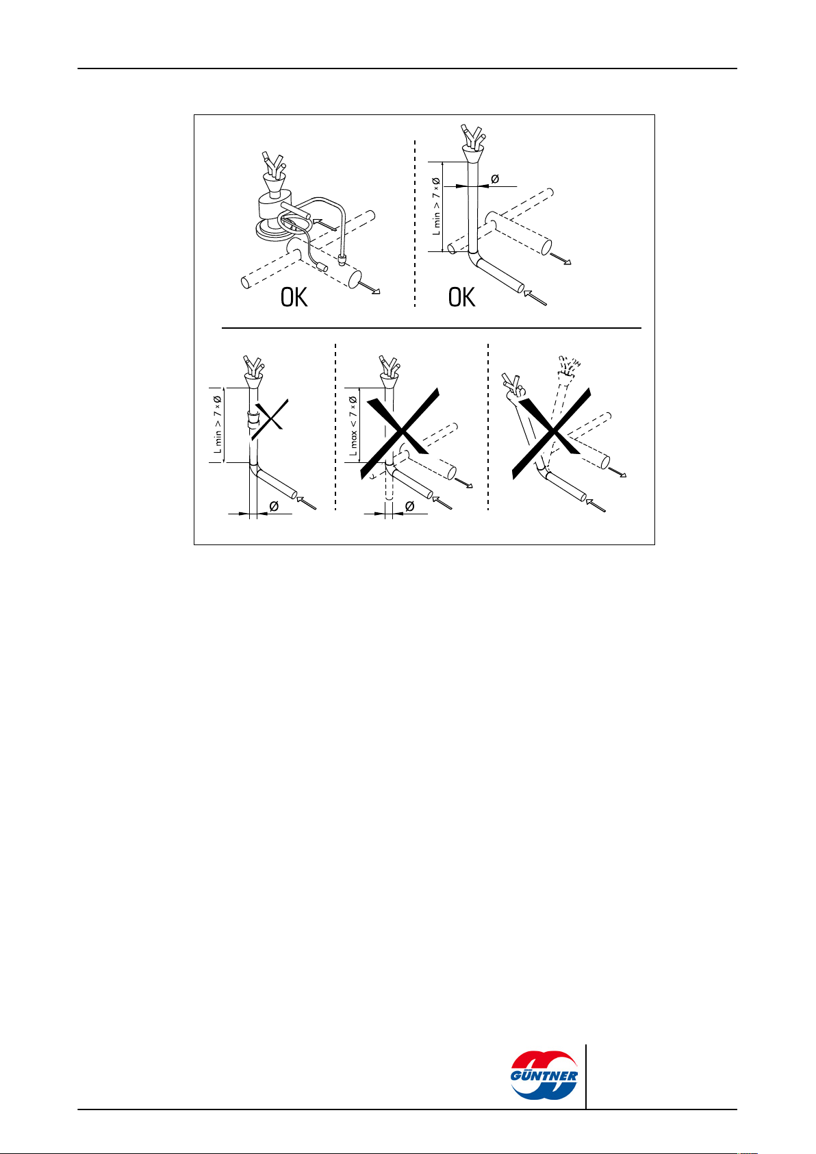
7.5.1 Connecting the thermostatic expansion valve..................................45
7.5.2 Connecting the drain line to the drip tray......................................... 45
7.5.3 Connect the unit to the system........................................................ 46
7.5.4 Unit electrical connection and protection......................................... 47
7.6 Perform acceptance test................................................................48
7.7 Test readiness for operation......................................................... 49
7.8 Putting the unit into operation for the first time......................... 49
CXGDF.1 | 2015-12
© Güntner GmbH & Co. KG
Page 4

page 4 / 68
8 Operation................................................................................... 51
8.1 Safety............................................................................................... 51
8.2 Putting the unit into operation......................................................51
8.3 Taking the unit out of operation...................................................51
8.4 Shutting the unit down.................................................................. 52
8.5 Putting the unit into operation after a shutdown........................ 53
8.6 Changing the unit over to another working fluid........................ 53
9 Troubleshooting........................................................................ 54
9.1 Safety............................................................................................... 54
9.2 Service............................................................................................. 54
9.3 Troubleshooting table....................................................................54
9.4 Dealing with faults......................................................................... 55
10 Maintenance...............................................................................56
10.1 Safety............................................................................................... 56
10.1.1 Before starting all maintenance........................................................56
10.1.2 With all maintenance work............................................................... 56
10.1.3 After all maintenance work...............................................................58
10.2 Inspection and maintenance plan................................................ 58
10.2.1 Fans.................................................................................................. 59
10.2.2 Unit heat exchanger......................................................................... 59
10.3 Maintenance work.......................................................................... 61
10.3.1 Remove leaks...................................................................................61
10.4 Clean unit........................................................................................ 61
10.4.1 General............................................................................................. 61
10.4.2 Clean heat exchanger...................................................................... 62
10.4.3 Cleaning fans....................................................................................63
10.5 Defrosting the unit......................................................................... 64
10.5.1 Notes on defrosting.......................................................................... 64
10.5.2 Defrost control.................................................................................. 65
10.5.3 Circulation air defrosting...................................................................66
10.5.4 Electric defrosting (optional)............................................................. 66
10.5.5 Further notes on defrosting.............................................................. 67
CXGDF.1 | 2015-12
11 Plans/diagrams..........................................................................68
11.1 Electrics documentation................................................................68
11.1.1 Fan motor connection diagram........................................................ 68
11.1.2 Connection diagram electrical defrost (selectable option; accessory
on customer request)....................................................................... 68
© Güntner GmbH & Co. KG
Page 5
page 5 / 68
1 Important basic information
1.1 Safety instructions
1.1.1 Observing operating instructions
CAUTION
Always keep the operating instructions in the unit's immediate vicinity at all times.
Ensure that the operating instructions are accessible to all people that have anything at all to do with
the unit at all times.
Ensure that the operating instructions are read and understood by all people that have anything at all
to do with the unit.
1.2 Importance of the EN 378 series of standards – refrigeration systems and heat pumps – safety-related and environmental requirements
EN 378 deals with safety-related and environmental requirements for designing, constructing, producing, installing, operating, maintaining and disposing of refrigeration systems and cooling equipment.
EN 378 is oriented towards manufacturers, installers and operators of refrigeration systems and
cooling equipment (see section 1.2. Responsibilities).
The objective of EN 378 is to restrict the possible hazards of refrigeration systems, cooling equipment and their working fluids (refrigerants and coolants) for people, property and the environment
to a minimum.
Insufficient safety measures or non-compliance with safety-relevant regulations can result in:
•
Breaks or ruptures on components with the danger of escaping materials (hazards caused by
the influence of low temperatures, excess pressure, direct influence of the fluid phase, moving
machine parts).
•
Escaping working fluid after a break or leak because of defective design, improper operation, insufficient maintenance, repairs, filling and disposal (hazards caused by damage to health, frostbite, suffocation, panic).
1.3 Responsibilities
1.3.1 Manufacturer's responsibilities
The notes provided in these operating instructions on maintaining the unit's functional safety, preventing possible hazards when transporting, setting up and installing, start-up and operation, and
with maintenance activities (cleaning, servicing and repairing) refer exclusively to the unit.
The manufacturer's responsibilities are documented in the unit's version in acc. with EN 378-2 (design, manufacture and testing).
CXGDF.1 | 2015-12
The materials used in the construction and for soldering and welding are designed to withstand
the foreseeable mechanical, thermal and chemical stresses, and are resistant to the working fluids
used and to mixtures of such working fluids and the oils used to lubricate refrigeration compressors.
© Güntner GmbH & Co. KG
Page 6

The working fluid-carrying parts of the unit (core tubes, distributor tube and header outlet) are configured so that they remain tight with the foreseeable mechanical, thermal and chemical stresses,
and withstand the maximum permissible operating pressure.
Material, wall thickness, tensile strength, corrosive resistance, shaping process and testing are suitable for the working fluid used and withstand the possible pressures and stresses that might occur.
All responsibility for the equipment into which the unit is integrated, are the exclusive responsibility
of the people involved in the individual workflows.
1.3.2 Responsibilities of the system’s installer
The responsibilities of the system installer are documented in the system’s version (design, manufacture and testing – in accordance with EN 378-2.
Component supplier-system installer interfaces :
•
In the event of any malfunction, inform Güntner GmbH & Co. KG :
Inform Güntner GmbH & Co. KG immediately if faults occur during the set-up, installation, startup and operation..
The responsibilities of the system installer in particular include:
•
Planning and preparing emergency measures:
To avoid consequential damage caused by operational disruptions, a warning system which immediately signals all faults must be provided on-site. Prepare emergency measures that prevent
consequential damage for people and property should faults occur.
•
Specify checking and maintenance intervals:
The system must be configured and equipped with all required equipment for maintenance and
sufficient servicing and testing in accordance with EN 378-4.
When the unit is integrated into the refrigeration system , the working fluid and version must not deviate from the order-related information specified in the order-related documents.
page 6 / 68
The installer of the system must refer to the requirement for sufficient instruction of the operating
and supervision staff when operating and maintaining the equipment .
It is recommended that the future customer staff – if possible – be present during the set-up and installation, for tightness tests and cleaning, while the system is being filled with working fluid and for
the adjustment of the equipment .
1.3.3 Owner or operator responsibilities
The owner or operator responsibilities are documented in the operation, maintenance, servicing
and recovery of the system in accordance with EN 378-4.
The owner or operator must ensure that the proper people are sufficiently trained and qualified for
operating, monitoring and servicing the system .
The operating personnel for the system must have sufficient knowledge and experience with regard
to the mode of operation, operation and daily monitoring of this system .
Before starting up the system, the owner or operator must ensure that the operating personnel are
sufficiently instructed about the system’s documentation (which is part of the operating instructions)
on the set-up, monitoring, mode of operation and servicing of the system and the safety measures
to be observed, and with regard to the properties and handling of the working fluid to be used.
The owner or operator must ensure that when operating, monitoring and maintaining the system
the working fluid and version must not deviate from the details specified in the order-related documents.
CXGDF.1 | 2015-12
© Güntner GmbH & Co. KG
Page 7
Planning and preparing emergency measures: To avoid consequential damage caused by operational disruptions, a warning system must be installed on the customer's premises. Prepare emergency measures that prevent consequential damage for people and property should faults occur.
Responsibility remains with the owner or operator of the system , if the system are used by anybody else, unless there is a contrary agreement on sharing responsibility.
1.4 Legal notes
Warranty claim expires as follows:
•
With faults and damages that can be attributed to non-compliance with the specifications of
these operating instructions.
•
With complaints that can be attributed to use of spare parts other than the original spare parts
specified in the order-related offer documents.
•
With changes to the unit (working fluid, version, function, operating parameters) vis-a-vis the or-
der-related information specified in the order-related offer documents without the manufacturer's
prior consent.
The operating instructions may not be reproduced electronically or mechanically, circulated,
changed passed on to third parties, translated or used otherwise, in full or in part, without Güntner
GmbH & Co. KG’s prior explicit written approval.
page 7 / 68
1.5 Operating instructions
1.5.1 Scope
1.5.2 Set-up and other applicable documents
These operating instructions apply to all CO2evaporators of the CXGDF.1 series.
You will find the precise type of your unit in the attached order-related documents.
The unit's operating instructions include the following parts:
•
These instructions
•
Order-related documents
The order-related documents are included with these instructions and contain the following in-
formation:
– The order-related proper use as specified
– The order-related scope of delivery
– The order-related technical data
– The order-related drawings specifying customer, project number and order number
•
Motor connection wiring diagram in terminal boxes
These operating instructions are part of the operating instructions manual of the system, provided
by the system’s installer .
NOTICE
CXGDF.1 | 2015-12
© Güntner GmbH & Co. KG
Page 8
1.6 Conventions
1.6.1 Typographical conventions
1.6.2 List of abbreviations
The following text markups are used in these operating instructions:
Bold Requires special attention!
Grey triangle Instructions
Abbreviations Meaning
page 8 / 68
CO
2
EN 378 European Norm 378: Refrigeration systems and heat pumps; safety-related
EN European Norm
DIN German industrial standard (specification of a standard)
ISO International Standardization Organization .
°C Degrees Celsius (Celsius scale temperature)
is Unit of pressure
I Litre (liquid volume)
Vol% Volume percent (concentration level relative to a volume)
IP Insulation protection
Q 6,3 Balancing quality
ppm parts per million, concentration figure, stands for “millionth part”.
Hz Hertz (frequency)
D Delta connection (alternating current: high speed)
S Star connection (alternating current: low speed)
3~ 3-phase current
CO2 refrigerant (R744)
and environmental requirements
CXGDF.1 | 2015-12
1~ 1-phase alternating current
VDE “Verband der Elektrotechnik, Elektronik und Informationstechnik” (Association
for Electrical, Electronic & Information Technologies)
TCC Technical Connection Conditions
EPC Electric Power Company
VDI “Verein Deutscher Ingenieure” (German engineers’ association)
© Güntner GmbH & Co. KG
Page 9
1.7 Conventions for safety signs and notices
1.7.1 General safety signs and their meaning in these operating instructions
DANGER
Dangerous situation that will definitely cause serious injury or death if it is not avoided.
WARNING
Dangerous situation that could cause serious injury or death if it is not avoided.
CAUTION
Dangerous situation that could cause slight to moderate injury if it is not avoided.
NOTICE
Refers you to possible damage to property.
page 9 / 68
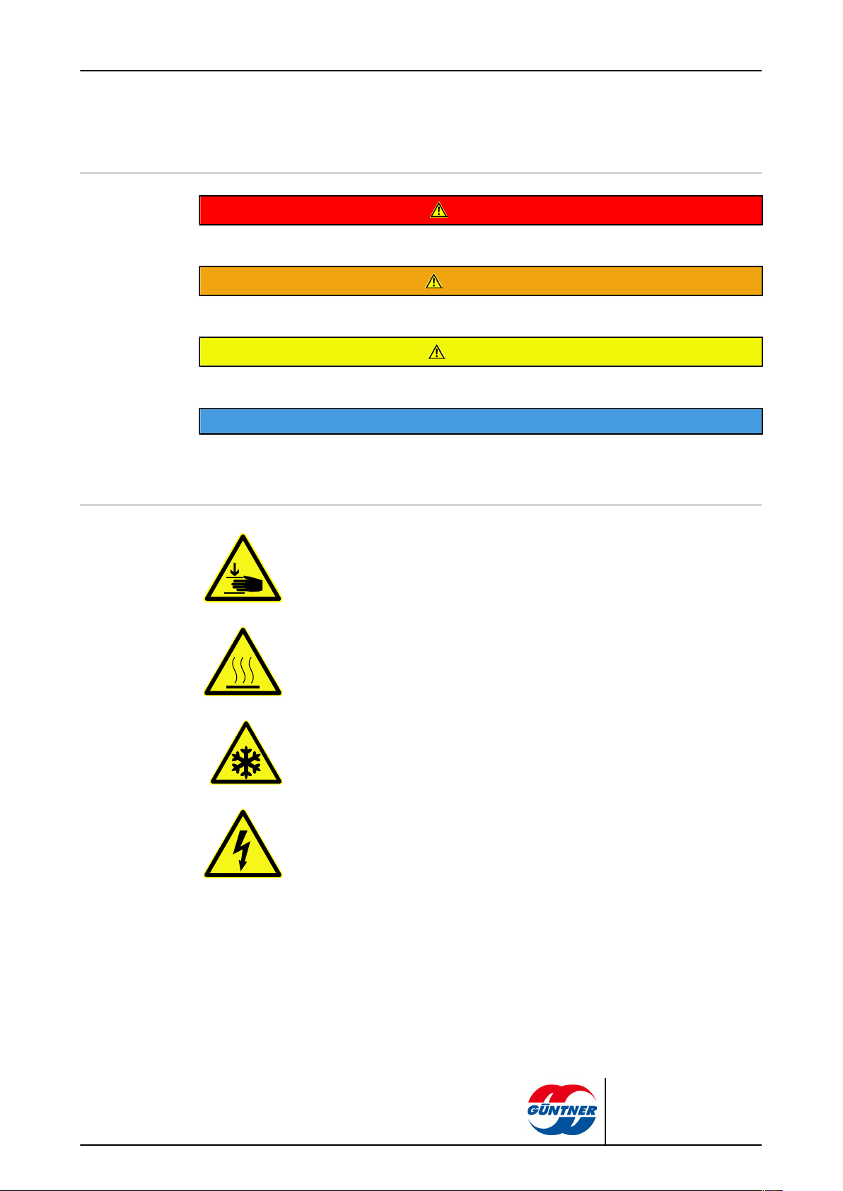
1.7.2 Warning symbols and their meaning in these operating instructions
Warns against hand injuries!
Failure to comply with warnings may result in hands or fingers being crushed,
dragged in or otherwise injured.
Warns against hot surfaces!
The temperature is over +45°C (at which protein clots) and can cause burns.
Warns against cold!
The temperature is below 0°C and can cause frostbite.
Warns against dangerous electrical voltage!
Danger of an electric shock if voltage-carrying parts are touched.
CXGDF.1 | 2015-12
© Güntner GmbH & Co. KG
Page 10
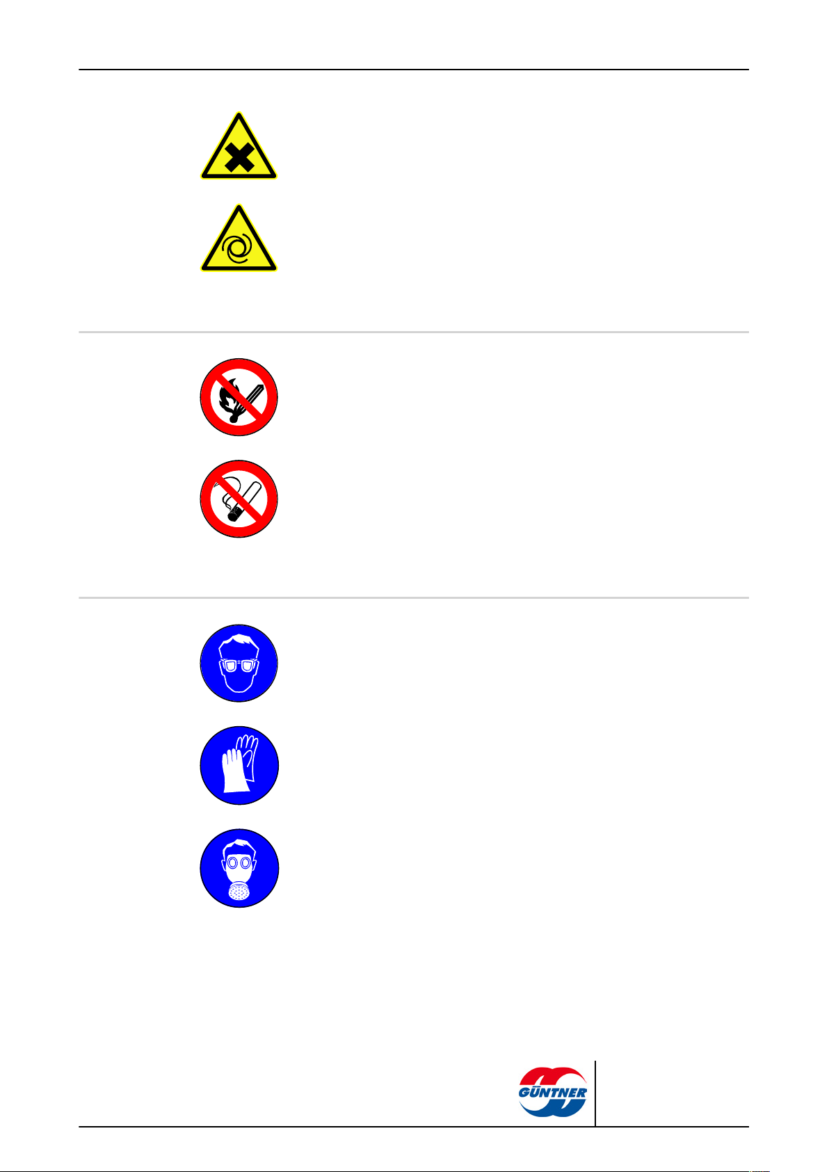
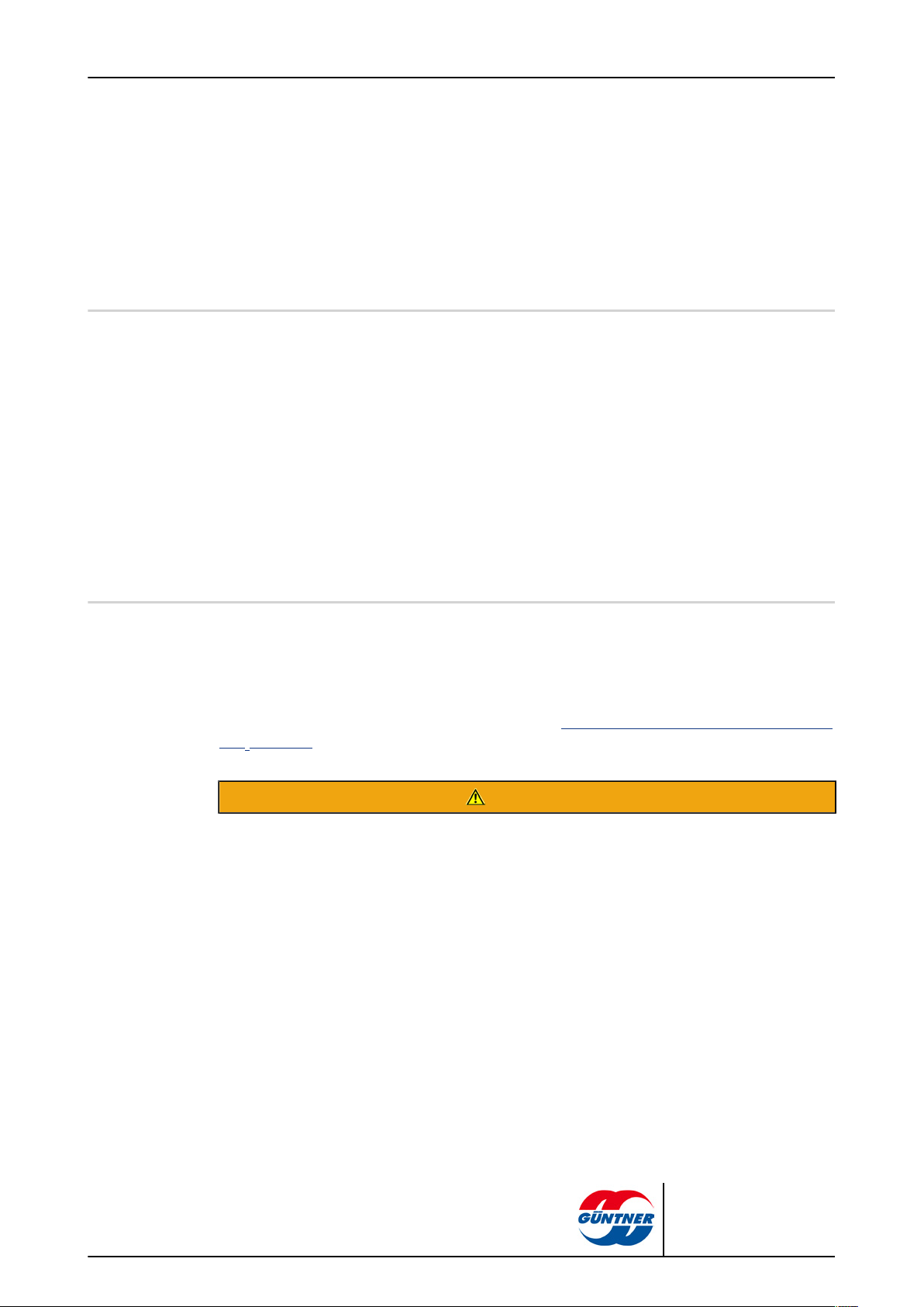
Warns against harmful to health or irritant substances at set-up point
Contact with or inhaling substances that are irritant or harmful to health can cause
injuries or damage peoples’ health.
Warning of automatic start-up
If the unit starts up automatically during maintenance work there is a danger of
pinching/trapping the hands and fingers.
1.7.3 Prohibitory signs and their meaning in these operating instructions
Fire, open fire and smoking prohibited!
Ignition sources must be kept away and ignition sources must not develop!
page 10 / 68
No smoking!
Smoking is forbidden.
1.7.4 Mandatory signs and their meaning in these operating instructions.
Use eye protection!
Eye protection: Use protective cover, protective glasses or face protection.
Use hand protection!
Protective gloves must protect against mechanical and chemical dangers (see imprinted pictograms).
Use respiratory protection!
Breathing apparatus must be suitable for the working fluid used. Breathing apparatus must consist of:
•
At least two independent breathing devices (self-contained breathing apparatus)
CXGDF.1 | 2015-12
© Güntner GmbH & Co. KG
Page 11
page 11 / 68
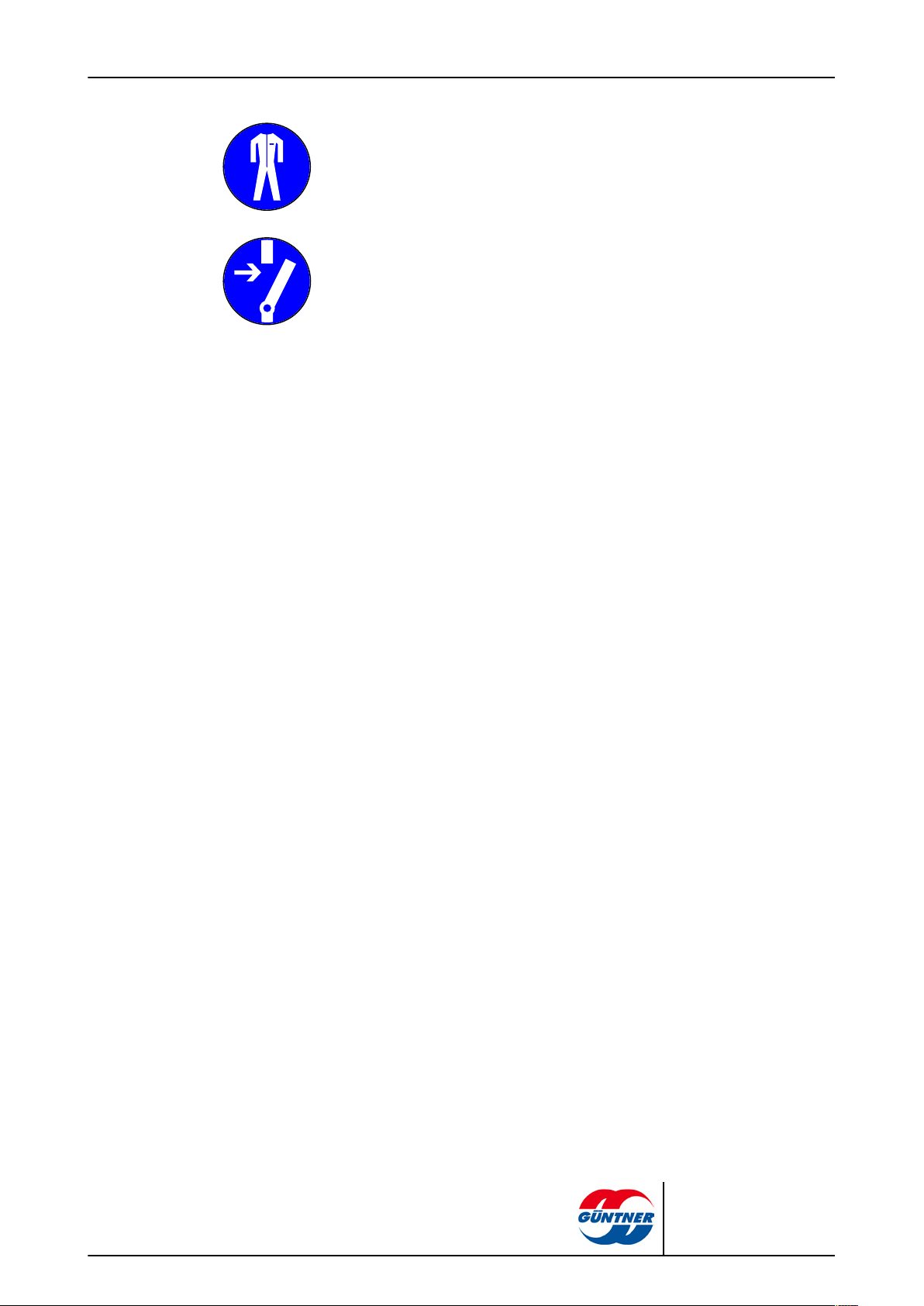
Use protective clothing!
Personal protective clothing must be suitable for the working fluid used and for low
temperatures, and must have good heat insulation properties.
Activate before work!
Activate the electrical system and secure against switching on again before starting installation, maintenance and repair work.
CXGDF.1 | 2015-12
© Güntner GmbH & Co. KG
Page 12
2 Safety
GDF.1 Typ A, B
GDF.1 Typ C
1
1
14
22
2
14
22
2
23
6
7
13
23
6
7
13
24
24
17
TÜV
GÜNTNER
GÜNTNER
ACHTUNG! CAUTION! ATTENTION!
ACHTUNG! CAUTION! ATTENTION!
ACHTUNG! CAUTION! ATTENTION!
ACHTUNG! CAUTION! ATTENTION!
Servickedeckel . Inspeczion door . Panneaude service
TÜV
Servickedeckel . Inspeczion door . Panneaude service
Auf
Open
Zu
Close
Auf
Open
Zu
Close
Prüfmedium
Aufgebrachter Prüfdruck PT
zulässige max./min. Temperatur TS
max./min. zulässiger Druck PS
Gerätebezeichnung
Herstellungsjahr
Herstellernummer
Projektnummer
WÄRMEAUSTAUSCHER
D-82256 FÜRSTENFELDBRUCK
INDUSTRIESTRASSE 14
HANS GÜNTNER GMBH
Ventilator-Typ/Nummer
Volumen V
Prüfdatum
c) Geräte vereinzeln
Unload units separately
Séparer, les appareils
b) Zum Vereinzeln
Transportschutz entfernen
Single unit
Remove transport protection
Appareil individuel
Enlever protection de transport
2. Montage
Mounting
Assemblage
a) Gesamt/ All units
Tous les appareil
1. Entladen
Unloading
Décharger
A
A
SW
13
SW1
3
SW
13
Prüfmedium
Aufgebrachter Prüfdruck PT
zulässige max./min. Temperatur TS
max./min. zulässiger Druck PS
Gerätebezeichnung
Herstellungsjahr
Herstellernummer
Projektnummer
WÄRMEAUSTAUSCHER
D-82256 FÜRSTENFELDBRUCK
INDUSTRIESTRASSE 14
HANS GÜNTNER GMBH
Ventilator-Typ/Nummer
Volumen V
Prüfdatum
2.1 Labelling on the unit:
Placing identifiers on the unit
page 12 / 68
Placing identifiers on the unit
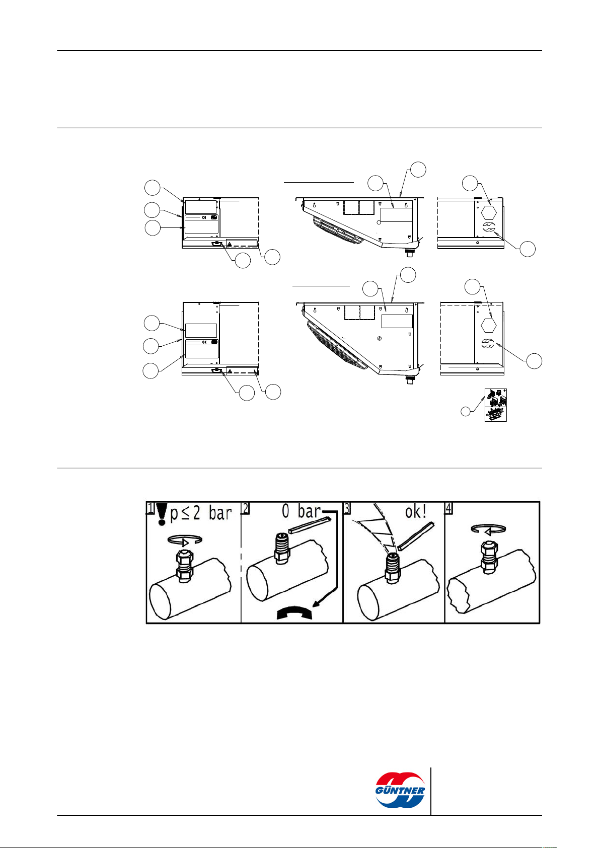
2.1.1 Safety signs on the unit
Safety signs on the unit individually:
940 - “Transportation filling” warning sign next to Schrader valve
CXGDF.1 | 2015-12
© Güntner GmbH & Co. KG
Page 13
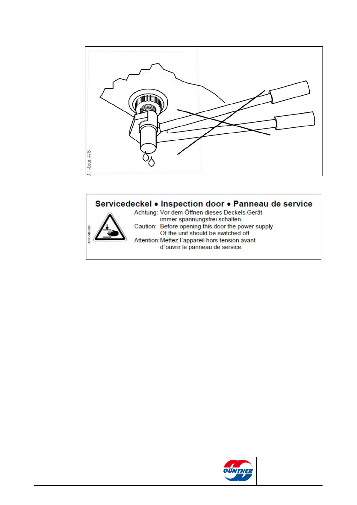
4413 - “Do not use wrench” warning sign beside tray drain
page 13 / 68
938 - Warning on inspection door (only with hinged fans)
CXGDF.1 | 2015-12
© Güntner GmbH & Co. KG
Page 14
page 14 / 68
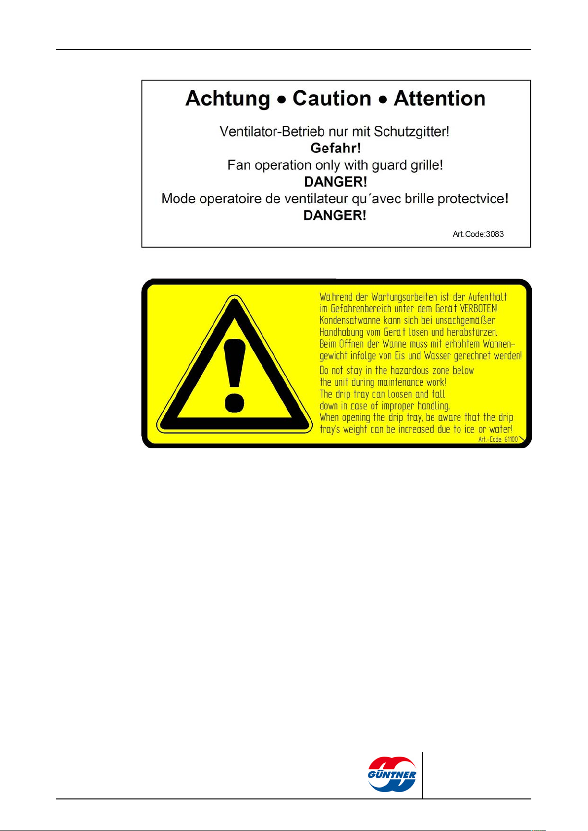
3083 - “Protection grill” warning sign (only used with separate removable protection grill)
61100 - Tray safety catch warning sign
CXGDF.1 | 2015-12
© Güntner GmbH & Co. KG
Page 15
2.1.2 Other signs and notes on the unit
page 15 / 68
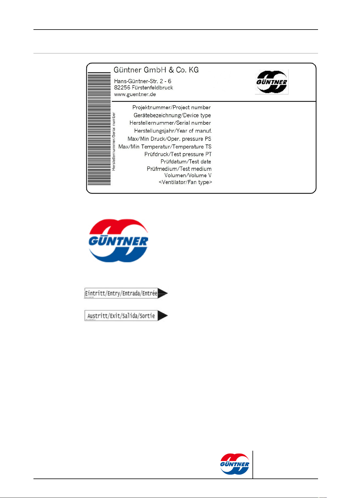
2483 - Example of a manufacturer’s nameplate
2119 – Logo
943 and 943.1 - Connections IN and OUT
CXGDF.1 | 2015-12
© Güntner GmbH & Co. KG
Page 16
page 16 / 68
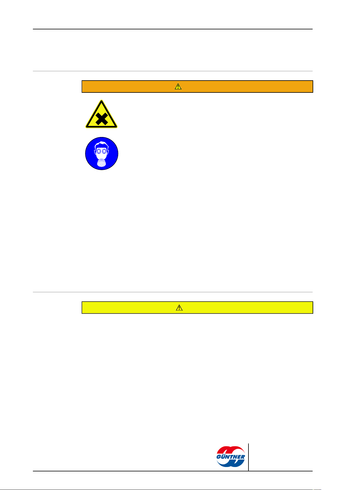
13 - Expansion valve mounting
CXGDF.1 | 2015-12
© Güntner GmbH & Co. KG
Page 17
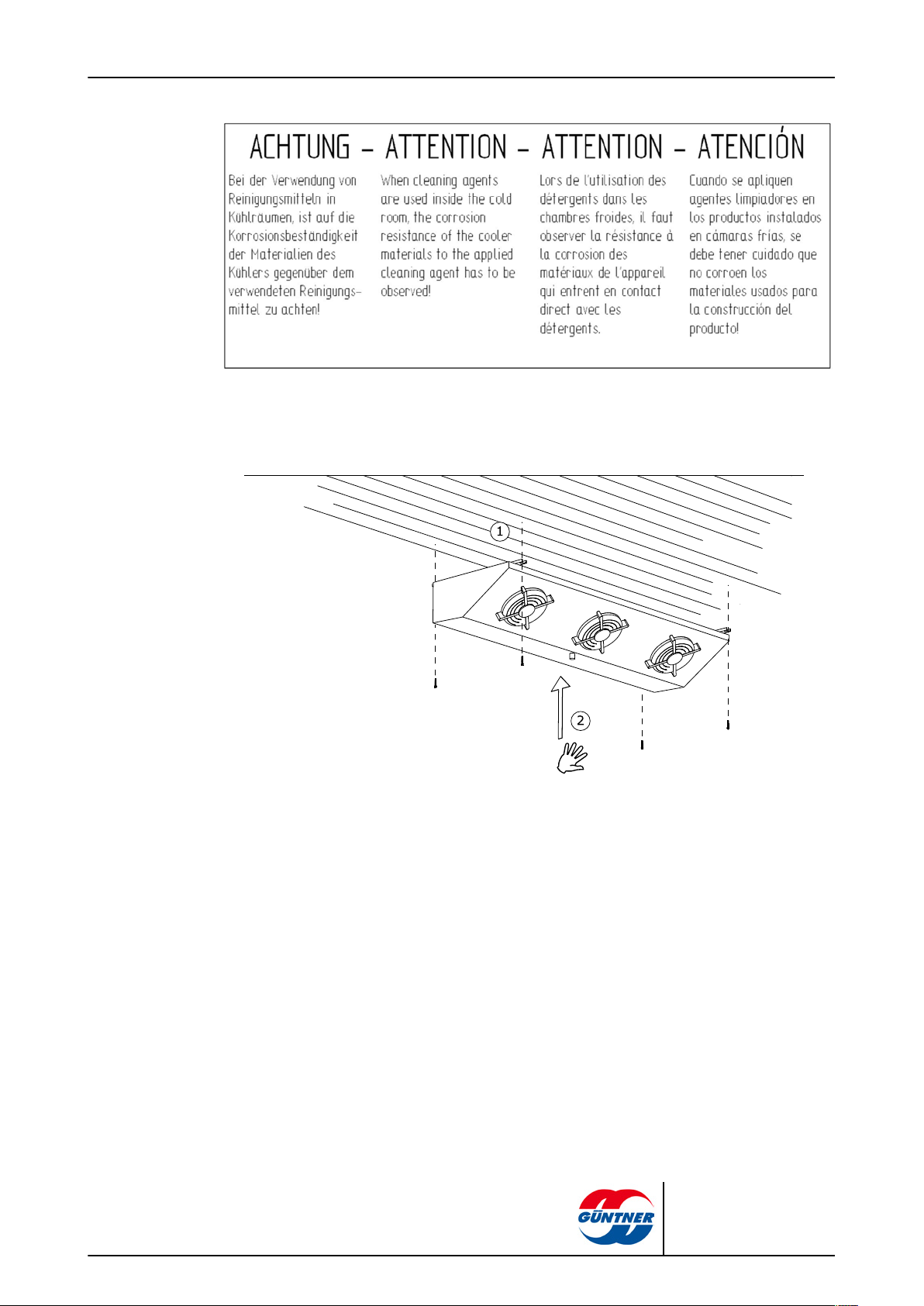
947 - Corrosion resistance
page 17 / 68
CXGDF.1 | 2015-12
Installation
© Güntner GmbH & Co. KG
Page 18
2.2 Basic safety notices
2.2.1 How to act in an emergency
Danger of injuries and damage to property!
CO2 is an irritant gas and when inhaled causes agitation, dizziness, vomiting and
cramps; with heavy concentrations suffocation and life-threatening pulmonary oedema.
Irritation of the respiratory centre with 30,000 to 50,000 ppm (3 to 5 vol %).
Unconsciousness with 70,000 to 100,000 ppm (7 to 10 vol%).
Safety measures and procedure:
•
In the event of serious unexpected leakage of refrigerant, leave the set-up room immediately and activate the emergency measures provided, e.g. if:
– Visibly escaping refrigerant liquid or vapour from the heat exchanger or tube
components.
– Sudden large release (release and evaporation of the greater part of the entire
refrigerant filling in a short time, e.g. in less than 5 minutes).
– Sudden irritation of the respiratory centre
– Activation of the NH2 alarm device (NH3 concentration > 5,000 ppm - MAC val-
ue):
•
Have experienced, trained personnel with appropriate protective clothing perform all
necessary protective and other measures:
– Use respiratory protection.
– Use a room air-independent breathing apparatus for maintenance work in high
CO2concentrations in the room air.
– Ensure the set-up room is well ventilated.
– Divert escaped refrigerant vapour and escaped refrigerant liquid safely.
page 18 / 68
WARNING
2.2.2 Personnel, care requirements
The unit may be installed, put into operation, operated, maintained and repaired only by trained, experienced and qualified personnel. In order to be considered qualified, people who are to be responsible
for the operation, maintenance, repair and evaluation of systems and their components must have the
necessary training and specialist knowledge for such work, as stipulated in EN 378-1. Qualified or expert means the ability to satisfactorily perform the activities required for the operation, maintenance, repair and evaluation of refrigeration systems and their components.
The unit may be operated by operating personnel that have no specific knowledge of refrigeration engineering, but have sufficient knowledge and experience with regard to the mode of operation, operation
and daily monitoring of this system, . This operating personnel may not make any interventions or settings on the system.
Changes to the unit, which the manufacturer has first agreed to in writing, may only be made by the instructed and qualified personnel.
CAUTION
CXGDF.1 | 2015-12
© Güntner GmbH & Co. KG
Page 19
Electrical installation:
Work on the electrical equipment may only be performed by personnel that have the required expertise
(e.g. an electrician or an electro-technically instructed person), and who are authorised by the operator,
in compliance with the respective VDE regulations (and national and international provisions) and the
TCCs of the EPCs.
2.3 Proper intended use
2.3.1 Proper intended use
CO2 evaporators of the CXGDF.1 series are intended for installation in a refrigeration system and
are used for cooling and circulating the room air e.g. in cold storage rooms and cold storage cells,
etc. The slimline design of these evaporators, and the CXGDF.1 in particular, enables optimum
room use. The CXGDF.1 series is ideal for deep-freeze applications (with a recommended fin spacing of 7 mm).
The unit is delivered for operation with a specific operating point:
•
Evaporation temperature
•
Airflow volume
•
Air inlet temperature
•
Relative air humidity.
The specified operating point is given in the order-related documents.
page 19 / 68
2.3.2 Operating conditions
The unit is a component a cooling system including its working fluid circuit. The purpose of these
operating instructions, as part of the operating instructions manual (of which these operating instructions are a part), is to minimise the danger to people and property and the environment from
the unit and the working fluid used in it. These dangers are essentially connected with the physical and chemical properties of the working fluid and with the pressures and temperatures that occur in the working fluid-carrying components of the unit see Residual hazards due to carbon dioxide
(CO2), page 23.
Danger of injuries and damage to property!
The unit may be used only in accordance with the proper intended use. The operator must ensure that
when operating, monitoring and maintaining the unit, the fluid used and the mode of operation do not
deviate from the order-related information specified in the order-specific documents.
The operator must ensure that maintenance measures are performed in compliance with the system’s
operating instructions manual.
Filling the unit with a different fluid is permitted only following written approval by the manufacturer. You
will find the order-related proper use as intended in the order-specific documents.
Do not exceed the max. operating pressure given on the unit’s type plate.
WARNING
CXGDF.1 | 2015-12
© Güntner GmbH & Co. KG
Page 20
2.3.3 Improper use
Danger of injuries and damage to property!
Working fluids and their combinations with water or other substances in the working fluid-carrying components have chemical and physical effects from the inside on the materials surrounding them. The unit
may be pressurised only with CO2. Pressurising the unit with another working fluid would have the effect
that
■
the structural, soldering and welding materials used do not withstand the foreseeable mechanical,
thermal and chemical stresses, and the pressure that can occur during operation and when shut
down is not withstood.
■
material, wall thickness, tensile strength, corrosive resistance, shaping process and testing are not
suitable for the working fluid used and do not withstand the possible pressures and stresses that
might occur.
■
the unit would not be resistant to the other working fluid and the combination of the other working fluid and
■
the unit not remaining tight during operation and when shut down.
■
a possible sudden escape of working fluids could directly endanger people and/or property and the
environment.
page 20 / 68
WARNING
The maximum permissible operating temperature specified on the type plate must not be exceeded! If
the operating temperature is exceeded,
•
the unit would be exposed to an impermissibly high pressure (pressure/temperature correlation),
•
signs of material fatigue would emerge,
The maximum permissible operating pressure specified on the type plate must not be exceeded! If the
operating pressure is exceeded,
■
the parts of the unit carrying the working fluid might not withstand the foreseeable mechanical, thermal and chemical stresses and the pressures that may occur during operation and when shut down,
■
the unit would not remain tight during operation and when shut down,
■
there may be a possible sudden escaping of working fluids after a break or leakage on working fluid-carrying components, which would result in the following dangers:
– Danger of escaping materials
– Fire hazard (caused by refrigerator oil parts)
– danger of frostbite (caused by liquid coolant squirting/splashing),
– Suffocation hazard
– hazards caused by panic reactions, agitation, dizziness, vomiting and cramps,
– Environmental pollution
WARNING
CO2evaporators may not be used
■
where it is possible that short or prolonged effect caused by contact, inhalation or ingestion of the
working fluid CO2 might result in harmful hazards.
■
where the possibility exists of a sudden large release (release and evaporation) of the greater part of
the entire working fluid filling in a short time (e.g. in less than 5 minutes).
CXGDF.1 | 2015-12
© Güntner GmbH & Co. KG
Page 21
page 21 / 68
■
where the possibility exists that the longest time that people are exposed to a large release of the
CO2 refrigerant is more than 60 minutes when the refrigerant concentration exceeds 5,000 ppm
(MAC value) and the number of clearly identified emergency exits for the number of usually present
people are not available.
■
where the number of clearly identified emergency exits for the number of usually present people are
not available.
The unit must not be changed without the prior written consent of Güntner GmbH & Co. KG . Changes
to the unit are:
■
Changing the operating point (as specified in section see Unit, page 31)
■
Changing the fan capacity (air volume)
■
Changing the working fluid flow-through volume
■
Changing over to another working fluid
The unit must not be operated if safety devices recommended by the manufacturer are not available, not
properly installed or not fully functional.
The unit must not be operated if it is damaged or demonstrates faults. All damage and faults must be
reported to Güntner GmbH & Co. KG immediately and dealt with promptly.
Work on the unit must not be performed without the personal protective equipment specified in these operating instructions.
2.4 Mechanical residual hazards
2.4.1 Fins, sharp unit corners and edges
Warns against hand injuries!
Danger of cuts on hands and fingers on the fins and on sharp corners and edges of
the unit.
Use reliable hand protection!
2.4.2 Flap down drip tray
WARNING
WARNING
CXGDF.1 | 2015-12
Warning against personal injury and damage to property!
Danger of falling unit parts, masses of water or ice when the drip tray is flapped out.
Nobody is allowed to be in the danger area below the unit during cleaning or maintenance work.
The drip tray can be flapped down for cleaning and is protected from falling down by a safety catch.
Unit parts, masses of water or ice can nonetheless fall down when it is flapped down.
© Güntner GmbH & Co. KG
Page 22

2.4.3 Fans
page 22 / 68
WARNING
Danger of cutting off, pulling in!
There is a danger of cutting off fingers on the rotating fan blades, injury hazard for the
hands and pulling in danger for loose elements such as hair, necklaces or clothing
parts.
Do not operate fans without guard grille. Pinch/trap point hazard!
With automatic fan start during maintenance work there is a danger of pinching/trapping for the hands and fingers.
Power off the unit before you begin maintenance work with which you must remove
the guard grille. Secure the unit against unintentional switching on again by removing
the electric fuses for the unit. Secure the unit with a suitable warning sign referring to
unintentional switching on.
The removable and hinged drip trays and the easy to open side covers must only be
opened by specialist staff and only for maintenance and repair purposes. Close the removable and hinged drip trays and the easy to open side covers after completing the
work and secure them against unintentional or unauthorised opening! Only open the
removable and hinged drip trays and the easy to open side covers after turning off the
fan's power (power-off state)!
2.4.4 Thermostatic expansion valve(option)
All work on the thermostatic expansion valve (e.g. overheating adjustment, changing nozzle uses) must only be performed by trained and instructed specialist staff. All
abovementioned work must be logged.
A nozzle use must only be changed with pressure-free line sections!
After changing a nozzle use the seal must be replaced!
When using a special expansion valve the screw for adjusting the set static overheating must be secured against unauthorized manipulations after every adjustment.
WARNING
CXGDF.1 | 2015-12
© Güntner GmbH & Co. KG
Page 23

2.5 Electrical residual hazards
Warns against dangerous electrical voltage!
Direct and indirect contact with voltage-carrying parts of motors and electrical lines can
cause serious injuries or death .
Power off the unit before you begin maintenance work. See the refrigeration system's
system documentation for this. Secure the unit against unintentional switching on
again by removing the electric fuses for the unit. Secure the unit with a suitable warning sign referring to unintentional switching on.
Please note that the mains cables may also be carrying voltage, even if the unit is
powered off.
Work on electrical equipment may be performed only by people that have the required
expertise (e.g. an electrician or an electro-technically instructed person) and who are
authorised to do so by the operator.
2.6 Thermal residual hazards
page 23 / 68
WARNING
2.6.1 Frostbite hazard
WARNING
Warns against cold!
In refrigerationoperation the heat exchanger and pipes have a temperature below ±0
°C. Contact can cause frostbite.
Use hand protection!
2.7 Residual hazards due to carbon dioxide (CO2)
The unit is operated with carbon dioxide (CO2). Carbon dioxide is a group L1/A1 refrigerant in ac-
cordance with classification according to flammability (L) and toxicity (A) in compliance with EU Directive 97/23/EG on pressure equipment (Pressure Equipment Directive):
– Refrigerants that, when gaseous, are non-flammable irrelevant of their concentration in air.
– Refrigerants with a time-weighted, averaged concentration that have no adverse effects on the
majority of staff that are exposed every day during a normal 8 hour working day and a 40 hour
working week to this concentration, which is greater than or equal to 400 ml/m3 (400 ppm (V/V)).
Carbon dioxide (CO2) as a refrigerant has the following properties:
CXGDF.1 | 2015-12
– Non-flammable, known fire extinguisher agent
– Non-toxic, food safety-approved and declaration-free
– Odourless
– Colourless
© Güntner GmbH & Co. KG
Page 24

page 24 / 68
– Taste-neutral
– Heavier than air
– Stable compound, used under normal ambient conditions as an inert gas
– Combination with water CO2 + H2O = H2CO3. Of dissolved CO2 gas in water, only 0.1% is
present as acid. The pH value of watery CO2 solutions at normal pressure is 3.7. Under pres-
sure it falls to a limit value of 3.3. CO2 is therefore suitable as a neutralisation medium for basic
solutions.
– Medical applications: Inhalations of 3 to 5% CO2 in breathing gas.
There is no imminent danger for the staff. With good air ventilation and removal by suction, it will fall
easily and clearly below the allowed limit values.
WARNING
Danger of harm to health and environmental damage!
Refrigerants of the Group L1/A1 are generally heavier than air and may flow off to rooms on a lower level. In still air there may be an increase of the ground level concentration. With high concentrations there
are the following hazards – especially near to the floor:
– Irritation of the respiratory centre with 30,000 to 50,000 ppm (3 to 5 vol %).
– Unconsciousness with 70,000 to 100,000 ppm (7 to 10 vol %) due to lack of oxygen.
– CO2 is an irritant gas and causes agitation, dizziness, vomiting and cramps, with high concentrations
causing suffocation and life-threatening pulmonary oedema.
Always observe the following safety instructions:
•
Unauthorised people must not have access to the unit.
•
Ensure working rooms are well-ventilated in order to prevent inhalation of high vapour concentrations. MAC value 5,000 ml/m3 (ppm) as 8 h average value; a concentration of 10,000 ppm (instantaneous value) for 60 min. three times per shift is permitted a peak limit.
•
Ensure that the CFC/HFC refrigerant escaping from the unit cannot penetrate the interior of the
building or put people at risk in any other way. CO2 refrigerant vapour or gas must be kept from pen-
etrating neighbouring rooms, staircases, yards, passages or drainage systems and must be discharged without risk.
•
Monitor the CO2 refrigerant concentration in the ambient air to ensure constant compliance with lim-
it values. With good air ventilation and removal by suction, it will fall easily and clearly below the allowed limit values.
•
With emergency work in high CO2 refrigerant concentrations in the room air wear a room air-inde-
pendent breathing apparatus.
•
Prevent the refrigerant or oil from escaping: Test the tightness of the unit regularly, as specified in
these operating instructions ( see Inspection and maintenance plan, page 58).
•
With leaks on the evaporator (escaping CO2), if hazard-free handling is guaranteed, the emergency
STOP switch must be pressed and the endangered unit shut off.
•
Harmful to the environment effects: CO2 must not be released into the atmosphere – environmental
damage (with a 50% content CO2 is one of the most significant anthropogenic greenhouse gases)
CXGDF.1 | 2015-12
© Güntner GmbH & Co. KG
Page 25

page 25 / 68
Ignition and fire hazard!
•
With work involving fire or sparks, e.g. grinding, welding, etc., ensure suitable fire
fighting equipment is on-site.
•
In particular be aware of the danger of ignition of oil residues unintentionally carried
in in the CO2 refrigerant.
•
Ensure that the provided fire fighting equipment is provided in sufficient quantities,
that it functions properly and that the extinguishing agent does not react with the
CO2 refrigerant.
•
Smoke during work is forbidden!
Frostbite hazard
Frostbite if CO2 comes into contact with the skin or eyes (-57°C). Leaks in the unit
can cause the CO2 refrigerant to escape into the set-up room.
•
When removing faults after spills of CO2 refrigerant, you must be vigilant for any re-
maining superheated CO2 refrigerant as splashes can cause frostbite and evapora-
tion can cause irritation.
Danger of poisoning!
CO2 refrigerant contact with fire can form toxic combustion products.
•
Prevent CO2 refrigerant contact with open fire.
•
Welding and soldering may therefore take place only after completely draining the
relevant section of the system of the CO2 refrigerant. Ensure good ventilation here!
•
With emergency work in high CO2 refrigerant concentrations in the room air wear a
room air-independent breathing apparatus.
2.8 Residual hazards caused by vibrations
WARNING
Danger of injuries and damage to property caused by escaping materials
If fans are damaged during fan operation, flying parts of the fan blades can injure people or cause damage to property close to the fan.
Fans, components and cables in system, must be designed, constructed and integrated so that dangers
caused by vibrations that it or other parts of the system generate ,, are reduced to an absolute minimum,
while incorporating all available means for reducing vibrations, preferably at the source.
CXGDF.1 | 2015-12
© Güntner GmbH & Co. KG
Page 26
NOTICE
Damage to property caused by vibrations
Vibrations that are increased by imbalances, as created by dirt, icing or fan blade damage, are regularly caused with fan operation. The vibrations are transferred to the unit, where they can cause damage
and damage the unit mounting or components connected to the unit.
Check fan blades and protection grill regularly for contamination and frost and/or ice and make sure
the fans run smoothly ( see Fans, page 59).
Check fan blades and protection grill regularly for contamination and make sure the fans run smoothly
(see Fans, page 59).
2.9 Residual hazards caused by pressurised parts
WARNING
Injury and damage to property caused by pressurised parts that contain CO2 refrigerant!
Breaks in pressurised pipes or pressurised components of the unit can cause injuries or damage to
property caused by escaping materials ( A sudden large release of the working fluid with its hazardous
properties after a break or leak on pressurised components of the unit can cause the following hazards:
■
Flammability (caused by proportion of lubricating oil for refrigerating compressors present)
■
Irritation of the respiratory centre
■
Frostbite (caused by liquid refrigerant squirting/splashing)
■
Suffocation
■
Panic, agitation, dizziness, vomiting and cramps
■
Environmental pollution
Ensure that the unit in question is pressure-free before maintenance work begins or remove the working
fluid from the unit in question.
page 26 / 68
Perform maintenance work – especially soldering and welding – on the unit in question only after completely removing the working fluid from the unit.
2.10 Residual hazards caused by defective installation
WARNING
Injuries and damage to property caused by defective installation!
Defective installation results in hazards caused by:
■
Break or leak on liquid-carrying unit components and pipes
■
Absence of release devices to prevent liquid escape: Observe the magnet valve/check valve se-
quence combination in the fluid line: In the flow direction the magnet valve must be installed first and
then the check valve. If the sequence is reversed, liquid will be locked in between the check valve
and the magnet valve when the magnet valve is closed; this will heat up during shutdown state and
can cause pipes or connection flanges to break when it expands. This applies in particular to lines
carrying cold liquids.
■
Subcooled liquid in system sections: If system sections are opened for repairs and the pressure is
equalised with the atmosphere, there is a danger that liquid, subcooled ammonia will still be present
in the opened area. Carbon dioxide has a very high evaporation heat, so that the heat penetration
in the pipes, for example, which are laid with a “fluid sack”, is not sufficient to evaporate the liquid re-
CXGDF.1 | 2015-12
© Güntner GmbH & Co. KG
Page 27

page 27 / 68
frigerant quickly – especially if this is an insulated line. This hazard is therefore referred to explicitly in
BGR 500.
■
Uneven load distribution on the fixtures with the danger of stresses within the unit or unit displace-
ment (breaks or leaks on fluid-carrying components of the unit and pipes; danger of breaking off).
■
Insufficient securing of working fluid-carrying lines against mechanical damage! On-site connections:
loaded installation; effect of forces on the distribution and header pipes with the danger of breaks or
leaks on fluid-carrying components of the unit and pipes; danger of breaking off!
■
Break-off and fall danger of the unit with hazard of escaping working fluid and exposed electrical ca-
bles.
■
Danger of damage caused by environment-conditional hazard sources (production, transport and
other processes at the set-up point).
■
Unit functional faults caused by air inlet/outlet obstructions.
■
Obstructed heater rods exchange with electric defrosting (accessory at customer’s request)/
■
Obstruction of all-side inspection, checks and maintenance, i.e. no unobstructed accessibility to the
working fluid-carrying and electrical components, connections and cables, no recognisable identifiers
on the pipes and insufficient space for tests.
Ensure that:
•
The units are to be installed on the fixing points corresponding with their weights and tightened with
fixing bolts. The operator or installer is responsible for ensuring that the bolted connections are of an
adequate strength.
•
The diameters of the mounting holes have been statically determined by the manufacturer and the
fixing bolts are adapted accordingly.
•
The fixing bolts are secured against loosening by means of an appropriate locking device.
•
The fixing bolts are not overtightened or stripped.
•
All fixing bolts are tightened equally to achieve a load distribution on the connections that is as bal-
anced as possible.
•
All fixing points maintain the same spacing to the fixing level permanently and under load, so that no
mechanical stress occurs in the unit structure. The units are anchored in their fixing position in order
to prevent the equipment from moving.
•
The functional safety of the fixing bolts is tested as part of the maintenance periods. see Mainte-
nance, page 56,
•
The unit is fixed and set up so that it is not damaged by environment-conditional hazard sources
(production, transport and other processes at the set-up point) or its functioning is not disturbed by
the interventions of unauthorised persons.
•
The units are fixed and set up with sufficient slopes for drip water flow.
•
The units are fixed and set up so that unobstructed air inlet/outlet is constantly available without any
air short circuiting.
•
The units are fixed and set up so that unobstructed heater rod exchange with electric defrosting is
constantly available (option: accessory at customer’s request).
•
The units are fixed so that they can be inspected, checked and maintained from all sides at all
times, i.e. there must be unobstructed access to the refrigerant-carrying and electrical components,
connections and lines, the pipeline labelling must be identifiable and adequate space must be avail-
able for testing.
•
The working fluid-carrying lines must be protected against mechanical damage. On-site connec-
tions: when installing keep the unit free of load; force must not be exerted on the distribution and
header pipes.
•
The following must be observed without fail when installing the unit:
– Imperative adherence to spacing from objects that could be endangered by a CO2 effect.
– Provision of measures to safeguard people from a CO2 concentration of more than 5,000 ppm
(MAC value).
CXGDF.1 | 2015-12
© Güntner GmbH & Co. KG
Page 28

– Set up and fix units as follows: In areas that are used for inner-plant traffic, the pipelines to and
from the unit must be installed only with connections and fittings that cannot be removed.
– Release devices to prevent liquid escapes must be provided and available.
– Subcooled liquid may be present in only the lowest possible amount in system sections in shut-
down state – minimized number of “fluid sacks”.
2.11 Residual hazards with break during operation
WARNING
Injuries and damage to property caused by break during operation!
•
Defective installation (see Residual hazards caused by defective installation, page 26).
•
Non-compliance with maximum permissible operating pressure ( see Operating conditions, page
19).
•
Disregarding pressurised line sections with maintenance ( see Residual hazards caused by pres-
surised parts, page 26).
•
Disregarding residual hazards caused by vibrations ( see Residual hazards caused by vibrations,
page 25).
result in ruptures during operation and maintenance. This results in dangers caused by
page 28 / 68
•
escaping materials (see Residual hazards caused by pressurised parts, page 26).
•
released working fluid (see Residual hazards due to carbon dioxide (CO2), page 23).
Ensure that:
•
The installation is fault-free.
•
The maximum permissible operating pressure is always adhered to.
•
Pressurised line sections are de-pressurised before all maintenance and repair work.
•
Vibrations from the refrigeration system, from the (vibrations caused by system compressors, , components and lines) and from the fan (imbalances caused by frosting, icing or dirt build-up or damages) are reduced with all available means and brought down to an absolute minimum.
•
Release devices to prevent liquid escapes are provided and available.
•
Undercooled liquid is only present in the lowest possible amount in system sections in shutdown
state – minimized number of "fluid sacks".
2.12 Residual hazards caused by escaping objects or liquids
WARNING
Injuries and damage to property caused by escaping objects or liquids!
Residual hazards caused by escaping objects and liquids ( see Residual hazards with break during oper-
ation, page 28).
CXGDF.1 | 2015-12
© Güntner GmbH & Co. KG
Page 29
2.13 Combined residual hazards
2.13.1 Easy to open side covers/
Danger of frostbite!
Danger of hand injuries!
With unauthorized access into the opened unit there is the danger of frostbite if heat
exchangers or pipes are touched, and the danger of cuts on sharp edges.
The easy to open side covers, and the removable and hinged drip trays, must only
be opened by staff and only for maintenance and repair purposes. Close the opened
side covers and the removable and hinged drip trays, after the work is completed
and secure them against unintentional or unauthorised opening!
2.14 Residual hazards with disposal
page 29 / 68
WARNING
WARNING
Danger of injuries and damage to property caused by working fluid, , CO2!
The following notes are recommendations for the proper professional disposal of the unit. Applicable
waste disposal laws are binding for the country of operation:
■
Disposal must only be carried out by experts.
■
All unit components, e.g. working fluids, refrigerator oil, heat exchangers, fans, must be disposed of
properly as specified.
■
Used working fluid that is not determined for reuse, must be treated as waste and safely disposed
of. There must be no emissions into the environment.
■
The CO2 refrigerant must be filled into a special refrigerant container in compliance with the respec-
tive safety measures. This special refrigerant container must be suitable for the CO2 refrigerant. It
must be easy to identify and labelled for the refrigerant, e.g. "Carbon dioxide (CO2) recovered".
■
A disposable single-use container must not be used, as refrigerant vapour residues in the container
escape during disposal.
■
The working liquid receiver must not be overfilled. The maximum permissible pressure of the working
fluid container must not be exceeded during the work process.
■
The working fluid must not be filled in a liquid container that contains another or an unknown working
fluid. This other or unknown working fluid must not be released into the atmosphere, but rather identified, treated again, or properly disposed of as specified.
■
An officially authorised facility can be used for destroying the working fluid.
■
It must be ensured that all unit components containing working fluids and refrigerator oil, are disposed of properly as specified.
CXGDF.1 | 2015-12
© Güntner GmbH & Co. KG
Page 30
page 30 / 68
■
The unit consists predominantly of the basic materials, copper, aluminium, (heat exchangers and
casings), steel and aluminium, copper, polyamide (motors), steel, copper, insulating material (heater
rods with electric defrosting – option; accessory at customer's request). These materials can be handled by the waste industry, including in paint-treated state, to recycling via mechanical and thermal
separation.
■
Before scrapping the working fluid-carrying unit components must be drained, whereby the pressure
must be reduced to at least 0.6 bar absolute for a unit pipe volume up to and including 200 l, and
to 0.3 bar absolute for a unit pipe volume over 200 l. The pressure reduction process is then ended
when the pressure no longer increases and remains constant, and the unit is at ambient temperature.
WARNING
Danger of environmental damage!
Carbon dioxide (CO2) is a greenhouse gas that appears in the most important natural compounds. Addi-
tional emissions from anthropogenic sources result in serious global warming and therefore damage to
the global climate:
– As an important, climate-relevant trace gas, carbon dioxide (CO2) contributes significantly to regula-
tion of the earth's heat balance. Carbon dioxide (CO2) changes the earth's radiation balance by al-
lowing (almost unobstructed) the short-wave solar radiation to pass through to the earth's surface,
and by partially absorbing the long-wave heat radiation emitted by the earth.
At 50 %, carbon dioxide (CO2) is one of the most significant anthropogenic greenhouse gases
•
Ensure that no refrigerant enters water systems or sewage.
•
Operate the facility for recovering or disposing of working fluids so that the danger of a working fluid
or refrigerator oil emission into the environment is kept as low as possible.
•
Ensure that carbon dioxide (CO2) never enters the atmosphere uncontrolled!
Güntner GmbH & Co. KG’s transportation packaging is made from environmentally compatible material and is suitable for recycling.
CXGDF.1 | 2015-12
© Güntner GmbH & Co. KG
Page 31
3 Technical data
3.1 Unit
The fans’ capacity values depend on the ambient temperature and on the air resistance at the set-up
point.
Güntner GmbH & Co. KG recommends electric fan ring heating with use in the temperature range.
Please consult the manufacturer when operating the unit below -40°C because of the special material
requirements and selection.
All electrical parts must be installed in accordance with EN standards.
Project number See order-related documents
Unit name See order-related documents
Manufacturer number See order-related documents
page 31 / 68
NOTICE
Production year See order-related documents
Working fluid R 744 (carbon dioxide, CO2)
Volume See order-related documents
Permissible operating pressure 32 bar
Test pressure 35.2 bar
Permissible operating temperature -60- +140 °C
Permissible ambient temperature -30- +40 °C
Permissible air humidity > 100%
Test date See order-related documents
Test medium Dry air
Airborne noise emitted See order-related documents In accordance with the
standard procedure for calculating sound level described
in EN 13487; Annex C (normative). As cold storage
rooms have only very low absorption behaviour, we recommend you to expect only very low absorption of the
sound level at large distances.
Weight See order-related documents
3.2 Fans
CXGDF.1 | 2015-12
The fans' technical delivery conditions comply with DIN 24166, accuracy class 2.
Fan type See order-related documents
Protection rating IP 54 in acc. with DIN 40050, thermal class 130
(B)
Current type alternating current (EC motors)
© Güntner GmbH & Co. KG
Page 32

Voltage 230 V 1~ 50 - 60 Hz
Permissible air temperature Operating range: -30°C to +40°C
page 32 / 68
Protective devices
•
Thermal: Thermo-contacts (temperature
monitor for safeguarding against thermal
overload).
•
Mechanical: Protective contact grille in acc.
with EN 294
CXGDF.1 | 2015-12
© Güntner GmbH & Co. KG
Page 33

4 Set-up and function
The air cooler consists of,
•
a heat exchanger arranged as consisting of pipe coils fitted with fins (copper pipe; aluminium
fin) distribution and header pipes (copper)/ and pipe connections to the pipeline system,
•
an aluminium-magnesium alloy casing, powder-coated RAL 9003 (signal white); brackets for
ceiling fixing made of stainless steel, flush with housing top edge;
•
a thermally-decoupled and therefore condensation-free drip tray made of AlMg, powder-coated
RAL 9003 (signal white). The drip tray is hinged and removable for easier cleaning.
•
and – depending on the version – with one or more axial fans with maintenance-free motors.
Two fan versions are possible here: normal and boosted (optional). High throw distances can be
achieved with Güntner streamers.
•
and – depending on the version – with one or more axial fans with EC motors.
The evaporator is a refrigeration system component. It provides a finned heat exchanger (straight
and curved pipes – pipe coils – with fins, which are connected to form a heat exchanger) in which
liquid refrigerant evaporates by absorbing heat from the material to be cooled.
The refrigeration system is a combination of refrigerant-carrying components and fittings connected
with one another, which form a closed circuit, in which the refrigerant circulates.
The refrigerant absorbs heat at a low temperature and low pressure and evaporates (evaporator-side), and at a higher temperature and higher pressure gives off the heat again and condenses
itself (condenser-side).
page 33 / 68
The heat from the material to be cooled is dissipated with fans over the entire surface of the evaporator.
The CXGDF.1 series evaporators standardly operate in accordance with the “dry evaporation” principle. The refrigerant liquid fed to the evaporator is completely evaporated in it, and overheated
to protect the compressor from slugging. The refrigerant used, R 744 (carbon dioxide, CO2), is a
Group L1/A1 refrigerant (see Residual hazards due to carbon dioxide (CO2), page 23).
CXGDF.1 | 2015-12
© Güntner GmbH & Co. KG
Page 34

5 Fan motor
During longer periods of storage or standstill, the fans must be activated during 2 to 4 hours per month.
For fans with the protection rating IP55 or higher, existing closed condensation water holes must be
opened at least once every six months.
AC technology
The AC motors are protected against overheating by a thermocontact (or PTC resistor).
For motors with a thermocontact, the thermocontact must be switched in such a way that the motor
cannot be powered on when the thermocontact is triggered. A locking mechanism is recommended
to prevent renewed power-on.
Motors with a PTC resistor need an additional external trigger unit for the installed thermistors. A
locking mechanism is recommended to prevent renewed power-on. The test voltage at the thermistors is not permitted to exceed 2.5 V, or only current-limiting test devices may be used.
page 34 / 68
NOTICE
NOTICE
When using a star-delta connection, a corresponding delay must be considered.
For motors with direct starting and a connection value > 4.0 kW, an inrush current limitation (soft
start using a thyristor) could be required.
If frequency converters are to be used for speed control, the following points must be considered for
external rotor fans:
Between the frequency converter and fans, all-pole sine-wave filters must always be installed (sine
wave-shaped output voltage; filter effect between phase to phase and phase to earth).
All Güntner frequency converters are equipped with this function as standard. Conventional threephase motors are suitable for direct operation with frequency converters.
With star-delta connection, the three-phase fan motors can be operated with two speeds or with
speed control. The direction of rotation must be checked. A change in the direction of rotation, if it is
wrong, is made by interchanging two phases.
CXGDF.1 | 2015-12
© Güntner GmbH & Co. KG
Page 35

6 Transportation and storage
6.1 Safety
Crushing danger with falling down!
The unit weighs between 9 kg and 80 kg. (when transporting 2 to 3 units packed on top of each other,
the transport weight is doubled or trebled). It can slip and fall off the transporting device, causing serious
injuries or death. Heavy impacts or vibrations can damage the unit.
Ensure that the assigned staff is trained for proper unloading.
Ensure that nobody is under the unit or near the loaded area during the transport.
Ensure even weight distribution. Ensure that the bulk of the weight is always on the fan side. Observe
the transport labels on the packed unit ( see Other signs and notes on the unit, page 15).
Secure the unit against slipping and mechanical damage.
Use auxiliary transport equipment where required. Use a transporting device appropriate for the unit’s
weight. You will find the weight of the unit in the order-related documents (see Set-up and other applic-
able documents, page 7). Do not use connection pieces and header pipes as hooking points for lifting,
pulling, fixing or mounting. This can cause leaks.
page 35 / 68
WARNING
Transport the unit carefully. Particularly avoid setting the unit down hard.
6.2 Transportation and storage
Read and observe all transport signs on the units’ packaging!
Prolonged mechanical stresses caused by uneven road surfaces and potholes and vibrations during
transport by ship can cause transportation damage. Before transportation by sea or in countries with difficult transport routes, attachment parts that are likely to vibrate – in particular fans and base stands –
must be removed for transportation.
NOTICE
CXGDF.1 | 2015-12
© Güntner GmbH & Co. KG
Page 36

page 36 / 68
Use suitable equipment to transport the packed unit to the destination installation site (for exam-
ple, a crane or fork-lift).
Unload the unit.
6.3 Storage before installation
Danger of corrosion and dirt build-up!
Moisture and dirt must be prevented from entering the unit.
Protect the unit against dust, dirt, moisture and wetness, damage and other harmful effects. Harmful
effects: see Safety instructions for set-up and start-up, page 37
Do not store the unit for longer than necessary. Only store the units in their original packaging until
installation. Always only place packaging units of the same size on top of one another.
Store the unit at a protected place free of dust, dirt, moisture and damage-free until its set-up
(well-ventilated halls or roofed storage site).
If the unit set-up is delayed with regard to the planned installation time: protect the unit against
weather and other harmful effects and dirt and other contaminants with an appropriate cover.
The unit must also be well-ventilated here.
NOTICE
CXGDF.1 | 2015-12
© Güntner GmbH & Co. KG
Page 37

7 Set-up and start-up
7.1 Safety
7.1.1 Safety instructions for set-up and start-up
WARNING
Danger of injuries and damage to property with escaping CO2 refrigerant!
Incorrect installation causes the danger of working fluid escaping when the unit is operated and injuries
or damage to property (see Residual hazards due to carbon dioxide (CO2), page 23).
Follow the set-up instructions in this chapter precisely and apply extreme care!
NOTICE
Damage to the system's !
Foreign materials and contaminants in the working fluid circuit can impair the effectiveness or damage
components. Particularly harmful contaminants are:
page 37 / 68
– Moisture
– Atmospheric air
– Welding and soldering residues
– Rust
– Soot/ash/cinders
– Metal cuttings
– Unstable oils
– Dust and dirt of all kinds
Moisture in the working fluid-carrying components of the unit can have the following consequences:
– Water separation and ice formation cause faults in the switching and control fittings of the refrigera-
tion system
– Acidification
– Ageing and refrigerator oil decay
– Corrosion
Atmospheric air and other non-condensable gases can have the following consequences:
– Refrigerator oil oxidation
– Chemical reactions between working fluid and refrigerator oil
– Increased condensing pressure in the system
Chemical reactions between working fluid and refrigerator oil with the absence of moisture or atmospheric air with ageing and working fluid and refrigerator oil decay can have the following consequences:
– Formation of organic and inorganic acids
– Increased compressed gas temperature in the system
– Corrosion
– Bad lubrication, increased wear and tear through to system or failure
CXGDF.1 | 2015-12
Other contaminants can cause:
– Accelerated chemical processes (decomposition)
– Mechanical and electrical faults in the refrigeration system
© Güntner GmbH & Co. KG
Page 38

page 38 / 68
During the installation (connecting the working fluid-carrying components of the unit to the working fluid-carrying system of the installation’s ensure that internal contamination is strictly avoided.
Perform the installation with extreme cleanliness.
Caution! Low permissible water content in a CO2 refrigeration system! Ensure that the unit's level of dry-
ness corresponds with the low permissible water content in a CO2 refrigeration system!
Finish all on-site pipe installation work before releasing the transport pressure!
Only release the transport pressure on the Schrader valve immediately before installation.
Only remove the sealing caps on the distribution and header pipe immediately before installation.
NOTICE
Danger of corrosion and dirt build-up!
Moisture and dirt must be prevented from entering the unit. If moisture and dirt penetrate the unit there
is also the danger of damage to fittings and other system components of the .
Protect the unit against dust, contamination, moisture and wetness, damage and other harmful influences. Harmful influences are, for example:
– Mechanical: Damages caused by impacts, objects falling on or against, collisions with transport
equipment, etc.
– Physical: Damages caused by close by concentrated flammable gases
– Chemical: Damages caused by contaminated atmospheres (salt, acid, chlorine, sulpher-containing,
or similar)
– Thermal: Damages caused by close by heat sources
Begin with the installation as soon as possible.
The electrical installation may be performed only by electricians (or by expert technicians with appropriate
qualifications) in compliance with the relevant VDE rules (or applicable national and international regulations) and the TCCs of the EPCs!
7.1.2 System-side safety requirements
The unit is a component of an installation and can only be operated in conjunction with the installation
•
All equipment required for operating the unit must be integrated into the switching and activation
equipment :
– Electrics: Fans and other electrical components, heating rods for electrical defrosting (op-
tional) if applicable,
– Working fluids: valves and fittings
– Drip water: drip water drain line
•
The working fluid-side and electrical connections must be available on the system. The connections must be specified in the order-related documents.
•
The power supply of the fans must be provided in acc. with the specifications on the type plate
on the fan motors.
•
A switch-off device for preventing unexpected start-up (repairs switch), which separates all active conductors from the power supply (all-pole switch-off), must be provided for the fans in acc.
with EN 60204-1.
•
The fans' switch-on/off device must be secured (e.g. with a padlock) to prevent uncontrolled fan
start-up.
WARNING
CXGDF.1 | 2015-12
© Güntner GmbH & Co. KG
Page 39

•
The electrical motor, repairs switch, terminal box and switching cabinet connections must be
provided in acc. with the respective connection diagrams.
•
It must be possible to shut off the unit if a leak occurs.
•
People wearing ambient air-independent breathing apparatus in full protective clothing must also be able to activate all safety-relevant shut-off fittings.
•
It must be possible to activate all devices meant for diverting escaping working fluids from a
safe position.
7.1.3 Customer-side safety precautions
Danger of injuries and damage to property!
The unit contains CO2 refrigerant (see Residual hazards due to carbon dioxide (CO2),
page 23).
CO2 is an irritant gas and causes agitation, dizziness, vomiting and cramps, with high
concentrations causing suffocation and life-threatening pulmonary oedema.
Irritation of the respiratory centre with 30,000 to 50,000 ppm (3 to 5 vol %). Unconsciousness with 70,000 to 100,000 ppm (70 to 100 vol %).
There is no imminent danger for the staff. However, refrigerants of the Group L1/A1
are generally heavier than air and may flow off to rooms on a lower level. In still air
there may be an increase of the ground level concentration. With high concentrations,
there is a danger of suffering from disordered cardiac rhythm and suffocation due to a
reduction of oxygen concentration, especially at ground level.
•
Ensure that unauthorised persons do not have access to the unit.
•
Ensure that the refrigerant escaping from the unit cannot penetrate the interior of
the building or put people at risk in any other way.
•
Comply with the requirements of EN 378-3 for refrigerants, filling weight and cold
transfer systems.
•
Install the unit in accordance with EN 378-1 only in the commissioned configuration
and only in a set-up room that the unit manufacturer has configured the unit for.
•
Install the unit in accordance with EN 378-3, section 5 in a special machine room if
a CO2 concentration of more than 5000 ppm (MAC value) could endanger the work
environment. Take effective protective precautions if such a spatial separation were
to be required, but is not possible.
•
Install the unit so that the MAC value – 5,000 ppm – as 8 h mean value is not exceeded. A concentration of 10,000 ppm (instantaneous value) for 60 min. three
times per shift is permitted as peak limit.
•
Install the electrical equipment (for fan operation, for ventilation, for lighting and for
the alarm system) in the set-up room while observing the condensation of moisture and formation of drip water, as well as the risk level of CO2 refrigerant in accor-
dance with EN 378-3; section 6.
•
Arrange CO2 refrigerant detectors and alarm systems to warn of CO2refrigerant
concentrations that are hazardous to health and for control purposes at the unit setup point in accordance with EN 378-3; section 7.
•
Ensure that the unit at the set-up point is not exposed to any inadmissible high
temperature effects. Effectively protect the unit against heat sources or temporary
high temperatures.
page 39 / 68
WARNING
CXGDF.1 | 2015-12
© Güntner GmbH & Co. KG
Page 40

Danger of environmental damage!
Carbon dioxide (CO2) is a greenhouse gas that appears in the most important natural compounds. Addi-
tional emissions from anthropogenic sources result in serious global warming and therefore damage to
the global climate:
– As an important, climate-relevant trace gas, carbon dioxide (CO2) contributes significantly to regula-
tion of the earth’s heat balance. Carbon dioxide (CO2) changes the earth’s radiation balance by al-
lowing (almost unobstructed) short-wave solar radiation to pass through to the earth’s surface, and
by partially absorbing the long-wave heat radiation emitted by the earth.
At 50%, carbon dioxide (CO2) is one of the most significant anthropogenic greenhouse gases
•
Ensure that carbon dioxide (CO2) never enters the atmosphere uncontrolled!
7.2 Requirements at the set-up point
You will find the dimensions and weights in the order-related documents.
Position the unit so that it cannot be damaged by internal traffic or transport processes.
page 40 / 68
WARNING
Enable optimum unit control and accessibility:
– Place the unit so that is can be monitored and controlled from all sides at all times.
– Ensure that sufficient space is provided for maintenance.
– Ensure that all liquid-carrying components, connections and lines and all electrical connec-
tions and lines are easy to access.
– Ensure that there is free space for the unobstructed exchange of heater rods for electric de-
frosting .
– Ensure that the pipes’ identification is well visible.
– Ensure that the free space in front of and beside the unit (e.g. the distance from the unit to
any possible obstructions) is big enough that the easy to open side covers and the remov-
able and hinged drip trays can be accessed hazard and obstruction-free.
CXGDF.1 | 2015-12
© Güntner GmbH & Co. KG
Page 41

7.3 Unpacking the unit
page 41 / 68
CXGDF.1 | 2015-12
Remove packaging 5, 6, 7, 8, 9, 10.
Remove the unit by loosening the bolts 4 from the transport frame 1, 2, 3.
CAUTION! The transport medium’s capacity must be at least 1.5-times the weight of the unit.
© Güntner GmbH & Co. KG
Page 42
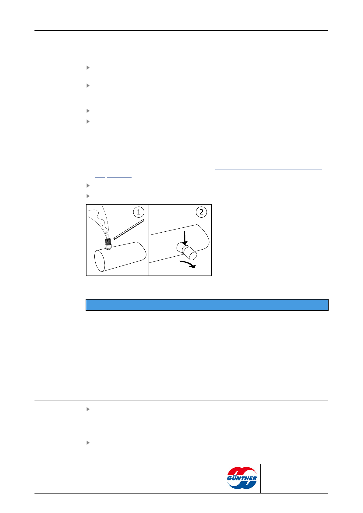
page 42 / 68
Check the delivery for completeness. You will find a list of the contents of the package in the order-related documents.
Any transport damage and/or missing parts must be recorded on the bill of delivery. The facts
must be immediately reported to the manufacturer in writing. Damaged fins can be straightened
on-site with a fin comb.
The units are delivered packed in the installation position.
Check transport overpressure: The units are delivered from the manufacturer with approx. 1 bar
transport overpressure (cleaned and dried air). Read the transport pressure on the Schrader
valve (pressure measurement). With unpressurised unit: Immediate report to manufacturer and
noting on bill of delivery. An unpressurised unit indicates a leak on the unit!
CAUTION! Danger of injuries and damage to property with escaping working fluid!
An unpressurised unit indicates a leak due to transport damage. Escaping working fluid
through leaks on the unit can cause injuries or ( see Residual hazards due to carbon dioxide
(CO2), page 23). Do not put the unit into operation!
Check transport pressure and release (only immediately before installation).
Remove blanking plugs.
1: Check/release transport overpressure / 2: Remove blanking plugs.
NOTICE
Danger of corrosion and dirt build-up!
Moisture and dirt must be prevented from entering the unit.
Protect the unit against dust, dirt, moisture and wetness, damage and other harmful effects. Harmful effects: see Safety instructions for set-up and start-up, page 37
Begin with the installation as soon as possible.
7.4 Installation
7.4.1 System-side requirements for stress-free installation
Prevent stresses in the unit:
°
Ensure that all fixing points have the same spacing to the fixing level.
°
Ensure that all fixing points maintain the same spacing to the fixing level under load and per-
manently.
Set up and fix units as follows: Airflow must not be impaired by obstructions.
CXGDF.1 | 2015-12
© Güntner GmbH & Co. KG
Page 43
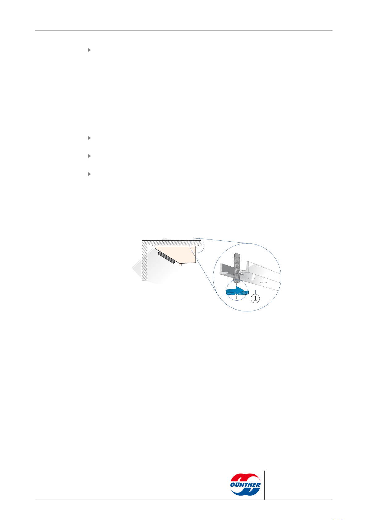
page 43 / 68
The units must be installed on fixing points that are appropriate for the unit's weight and then
bolted with fixing bolts. The operator or installer of the equipment is responsible for ensuring
that the bolted connections are of an adequate strength. The following instructions must be observed when fixing the units:
– The diameter of the mounting holes have been statically determined by the manufactur-
er; the fixing bolts must be adapted accordingly. When calculating the transferring bearing
strength it is imperative to take into account the total weight of the unit (= structural weight +
weight of pipe content + additional weight, such as water, frost, ice, dirt or similar).
– The fixing bolts must be secured against loosening with an appropriate locking device.
– The fixing bolts must not be overtightened or stripped.
– All fixing bolts must be tightened equally.
Prevent the unit from shifting in its position. Fix the unit in its position. Tighten the fixing bolts
and secure then against loosening.
Ensure that the drip water drains correctly. Set up the unit horizontally with a sufficient slope for
the drip water run-off. The units are delivered in the installation position with mounted drip tray.
Only fix the unit to the intended fixing points.
CXGDF.1 | 2015-12
1
Fixing of unit as described above
© Güntner GmbH & Co. KG
Page 44

7.4.2 Mounting the unit
page 44 / 68
Only fix unit to fixing points intended for this (1).
Remove installation support (2).
The units are delivered with mounted drip tray and have to be turned by 180° for installation position.
7.5 Notes on connecting the unit
Danger of injuries and damage to property with escaping CO2 refrigerant!
Incorrect installation risks working fluid escaping when the unit is operated, causing injuries or damage to
property (see Residual hazards due to carbon dioxide (CO2), page 23).
Prevent working fluid from escaping from the unit into the environment.
•
Secure all working fluid-carrying lines against mechanical damage.
•
In areas that are used for internal traffic, only lay the pipelines to and from the unit with connections
and fittings that cannot be removed.
Ensure that the on-site connections do not exercise any forces upon the distribution and header points.
This can cause leaks on the working fluid connection points of the unit and on connection points of the
on-site pipe-laying.
Ensure that:
WARNING
CXGDF.1 | 2015-12
•
Release devices to prevent liquid escapes are provided and available.
•
With refrigeration system shutdown state, under-cooled liquid is only present in the lowest possible
amount in system components – minimized number of "fluid sacks".
•
When switching over a duty pump to a reserve pump no liquid, cold working fluid remains in the
pump.
© Güntner GmbH & Co. KG
Page 45

7.5.1 Connecting the thermostatic expansion valve
The expansion valve and the heat carrier distributor are connected to the system as follows:
page 45 / 68
Connections
NOTICE
After mounting, check that the capillary tubes of the refrigerant distributor are not blocked.
Vibration can cause mechanical damage and leaks.
It is important to carefully position the capillary tubes, if necessary using e.g. plastic cable ties to fasten
them in place, to prevent vibration causing them to collide with one another or with other objects.
7.5.2 Connecting the drain line to the drip tray
Please observe the following instructions with the installation:
Lay drain line completely strain-free. The diameter of the drip water drain line must be at least
that of the drip water drain of the unit, and the drip water drain line should be laid with a slope (3
– 5°).
Tighten connection nuts with the hand only!
CXGDF.1 | 2015-12
© Güntner GmbH & Co. KG
Page 46

page 46 / 68
NOTICE
Danger of damaging! The plastic threads can be damaged by over-tightening if you use a wrench.
This results in leaks with drip water damage on the produce to be cooled. Do not tighten the con-
nection nuts with a wrench!
7.5.3 Connect the unit to the system
Danger of injuries and damage to property!
Improper connection to the the system causes hazards:
•
Leaks result in escaping CO2 refrigerant (see Residual hazards due to carbon dioxide (CO2), page
23).
•
Soldering and welding work on pressurised parts can result in fires or explosions.
•
Smoking or open light can cause .
•
Ensure that stresses and vibrations from the system are not passed on to the unit.
•
Only lay working fluid-side connections stress-free! The on-site pipeline system must be braced be-
fore connecting to the unit!
•
Soldering and welding work is only permitted on unpressurised units!
•
Evacuate the unit professionally in acc. with EN 378-2.
•
Ensure that the unit's level of dryness corresponds with the low permissible water content in a CO
refrigeration system!
•
The use of open fire at the installation site is forbidden. Fire extinguishers and extinguishing agents
used to protect the equipment and the operating staff must comply with the requirements of EN
378-3.
•
Ensure that refrigerant detectors and alarm systems for warning about fire dangers, and for control
purposes at the unit set-up point are arranged in acc. with EN 378-3; section 7.
WARNING
2
CXGDF.1 | 2015-12
Install the pipes in acc. with EN 378-1 and EN 378-3. Ensure here:
– That the connections are easy to access with the opening side covers and the removable and
hinged drip trays.
– Release devices to prevent liquid escapes must be provided and available.
– That the pipeline installation is kept as short as possible. Use as few bends as possible, and if
bends are necessary, use big radii!
© Güntner GmbH & Co. KG
Page 47

page 47 / 68
– Avoid transmitting vibrations to the unit via conduits or pipes. If necessary, use vibration
dampers.
– Always lay the fluid supply and return lines separately from one another. Make sure they do not
touch.
– The free space around the unit (e.g. the distance from the drip tray underside to any possibly
existing pipe systems) must be big enough to ensure there is no danger to the unit; regular
maintenance of the components must be possible, and it must also be possible to check and re-
pair components, pipes and fittings.
– It must be possible to shut off the unit if a leak occurs. It must be possible to activate all devices
used for diverting escaping working fluids from a safe position.
– Electrical components, e.g. for fan operation, for heater rod operation with electrical defrost, for
ventilation, for illumination and for alarm system on installation site, have to be designed with re-
gard to condensation of air humidity and droplet formation in acc. with EN 378-3; section 6.
– With connection of the liquid and suction line, the thermostatic expansion valve, including its
overheating sensor, must be protected against high heat stresses from the soldering process!
– Observe the following when soldering:
°
All connections must be hard-soldered!
°
Caution! Use silver solder with TS < -40 °C! Ask manufacturer about solder specification if
required!
°
Avoid percussive soldering joints; use copper pipe ends that are widened on one side (capillary soldering)!
°
Prevent leaks, solder precisely and carefully!
°
Prevent overheating when soldering (danger of excessive scaling)!
°
Use shielding gas when soldering (prevent excessive scaling)!
Caution! Low permissible water content in a CO2 refrigeration system! Ensure that the unit's lev-
el of dryness corresponds with the low permissible water content in a CO2 refrigeration system!
7.5.4 Unit electrical connection and protection
All fans with EC motors can be operated with two different speeds.
Connect fan motors in acc. with motor connection circuit and check connection.
Provide power supply in acc. with the specifications on the fan motor's type plate:
■
The fan motors are operated in 1 ~ alternating current
Connect thermo contacts for motor protection.
Where required, connect electrical feeds for the heater rods for electric defrosting in accordance
with electric connection diagram.
1
2
Defrost limit sensor position (if used)
Electrics (fan motor, stamp data, connection values)
CXGDF.1 | 2015-12
© Güntner GmbH & Co. KG
Page 48

Seal all electrical lines to the connection boxes in acc. with their protection class. The connection class is specified in the order-related offer documents.
Danger of damaging! If the fuse rating is too high there is the danger of injuries to people
and damage to property.
Max. fuse rating for the defrost heater rods feed : see order-related offer documents. The
supply lines must always be fused as appropriate for the smallest wire cross-section.
7.6 Perform acceptance test
Danger of injuries and damage to property!
Escaping CO2 refrigerant can cause injuries or even death ( see Residual hazards due to carbon dioxide
(CO2), page 23).
Perform the following acceptance test with an expert before starting up the unit after making important
changes and after a unit exchange.
page 48 / 68
WARNING
WARNING
Ensure that the temperature and the air humidity at the set-up point correspond with the technical data (see Technical data, page 31).
Ensure that sufficient air can be sucked in and released.
Ensure that the supply feed is sufficient for the required energy. Compare the unit inside of the
systemwith the plans of the systemand the electrical wiring diagrams.
Test the unit for vibrations and movements that can be caused by the fans and operation of the
system . Remove oscillations, vibrations and movements following consultation with the manufacturer or independently.
Perform visual inspection of the structural design, the brackets and fixtures (materials, sequence, connections), the ability to operate and the arrangement of the fittings.
Check that the tray installation with safety catch is correct.
Check and if necessary re-tighten all threaded connections, especially on the fans.
Check installation of pipe connections.
Check laying of working fluid-carrying connection pipes.
Ensure that the unit is protected against mechanical damage.
Ensure that the unit is protected against inadmissible heating up and cooling down.
Check the fan blades protection.
Ensure that optimum unit control and accessibility are guaranteed.
– Is the unit placed so that it can be monitored and controlled from all sides at all times?
– Is sufficient space provided for maintenance?
– Are all liquid-carrying components, connections and lines and all electrical connections and
lines easy to access?
– Are the pipes easy to identify?
Check heat exchanger surfaces for dirt and clean as required (see Clean unit, page 61).
CXGDF.1 | 2015-12
Perform function tests on the fans (rotation direction, power consumption, etc.).
© Güntner GmbH & Co. KG
Page 49

page 49 / 68
Check electrical connections of the fan motors and, where app., the heater rods with electric defrosting for damage.
Check the soldering and welding connections, the electrical connections and the fixture connections.
Perform pressure test with test gas and with a test pressure of 1.1-times the permissible operating pressure: check the connection seals and detect leaks, e.g. with foaming agent, or similar.
Check corrosion protection: Perform a visual inspection on all bends, components and component holders that are not heat-insulated. Document and archive test results.
Perform test run. Observe and check unit during test run, in particular for:
– Fan smooth running (bearing noises, contact noises, imbalances, etc.).
– Fan power consumption:
– Leaks
Report all defects to the manufacturer immediately. Remove defects following consultation with
the manufacturer.
Check the unit and the unit’s interaction with of the system again after 48 operating hours, especially on the connections and on the fans, and document the test results.
7.7 Test readiness for operation
Ensure that all electrical protective measures are ready to function.
Ensure that all working fluid-carrying connections are securely in place.
Ensure that all electrical connections (fans , if applicable heater rods for electrical defrost ) are
effected securely.
Ensure that all threaded connections on the fans, the unit fixing bolts and all other threaded connections are firmly tightened.
Ensure that the unit connection to the drip water drain line is properly set up (see Connecting
the drain line to the drip tray, page 45).
7.8 Putting the unit into operation for the first time
WARNING
Danger of injuries and damage to property!
Escaping CO2 refrigerant can cause injuries or even death ( see Residual hazards due to carbon dioxide
(CO2), page 23).
You can put the unit into operation, only when:
•
The unit has been properly mounted and connected ( see Installation, page 42).
•
You have performed a complete acceptance test (see Perform acceptance test, page 48).
•
You have checked the unit’s readiness for operation (see Test readiness for operation, page 49).
•
All safety precautions (see Safety, page 37) have been taken.
CXGDF.1 | 2015-12
Follow the operating instructions manual of the system!
Contact the manufacturer immediately if you want to operate the unit under different operating conditions
as those defined in the order-related offer documents.
© Güntner GmbH & Co. KG
Page 50

page 50 / 68
Switch on the system including of the electrical system (see system).
Activate the unit:
– Open the valves on the inlet and outlet-side system.
– Activate fans
– Put drip water waste line into operation
Wait until the operating point is reached. After the operating point is reach the unit is ready to
operate (see system).
Parameters for setting the operating point, see order-related offer documents.
Operating point:
•
Evaporation temperature
•
Airflow volume
•
Air inlet temperature
•
Relative air humidity
To ensure the specified operating point is complied with the actuators for the operating point setting
must be secured against unauthorized access (e.g. by sealing, screwing on caps, removing hand
wheels, etc.).
CXGDF.1 | 2015-12
© Güntner GmbH & Co. KG
Page 51

8 Operation
8.1 Safety
Danger of cutting off, pulling in!
Danger of frostbite/burning!
page 51 / 68
WARNING
There is a danger of cutting off fingers on the rotating fan blades, injury hazard for the
hands and pulling in danger with loose elements such as hair, necklaces or clothing
parts.
Do not operate fans without guard grille!
WARNING
Danger of frostbite or burns if the parts are touched ( see Thermal residual hazards,
page 23).
Do not touch any parts of the unit without protective gloves when the unit is in operation or if it has not yet warmed up or cooled down after operation.
8.2 Putting the unit into operation
To operate the unit the systemincluding the electrical system must be in operation. The unit must be
started up by opening the valves on the inlet and outlet side of the plantby connecting it to the electrical system and the drip water drain as described below (see system operating instructions manual):
Switch on electrical system
Open working fluid-carrying lines
Switch on fans
Put drip water waste line into operation
8.3 Taking the unit out of operation
The units are system components of a system. The unit is taken out of operation by switching off
the system in accordance with the system operating instructions manual. The working fluid-carrying
lines of the plant must be shut off here and the fans and, where applicable, the heater rods for electric defrosting must be disconnected from the electrical system (see system) operating instructions
manual:
CXGDF.1 | 2015-12
© Güntner GmbH & Co. KG
Page 52

Switch fans off
Switch electrical system off
Close working fluid-carrying lines
NOTE! When shut down consider max. operating pressure! If necessary, take precautions to
ensure that it cannot be exceeded, or drain the device.
With shutdown times of a month or longer put the fans into operation for approx. 2-4 hours a month to
maintain their functionality.
8.4 Shutting the unit down
Danger of injuries and damage to property!
Escaping CO2 refrigerant can cause injuries ( see Residual hazards due to carbon dioxide (CO2), page
23, and see Residual hazards caused by pressurised parts, page 26).
page 52 / 68
NOTICE
WARNING
Ensure that the maximum operating pressure is not exceeded after the shutdown either!
NOTICE
Danger of corrosion and dirt build-up!
Moisture and dirt must be prevented from entering the unit.
Protect the unit against dust, contamination, moisture and wetness, damage and other harmful influences (see Safety instructions for set-up and start-up, page 37).
With shutdown times of a month or longer put the fans into operation for approx. 2-4 hours a month to
maintain their functionality.
Take the unit out of operation (see Taking the unit out of operation, page 51).
Secure the unit:
– When shutdown consider max. operating pressure (see Technical data, page 31)! If neces-
sary, take precautions so that it cannot be exceeded.
– Secure the fan motor drives and, where applicable, the heater rods with electric defrosting
against switching on again.
– Secure working fluid-carrying lines against pressurizing with working fluid.
– Protect against damaging effects at the set-up point or intermediate storage location (see
Safety instructions for set-up and start-up, page 37), so that the unit’s components are kept
properly looked after and the proper intentional use and usability of the unit are maintained.
The corresponding storage conditions must be provided for this (see Storage before instal-
lation, page 36); precautionary corrosion protection measures, regular checking of the fans’
functionality and regular checks on the shutdown unit.
Evacuate the unit: Completely release working fluid and, if applicable, refrigerator oil (see
Residual hazards with disposal, page 29).
CXGDF.1 | 2015-12
© Güntner GmbH & Co. KG
Page 53

8.5 Putting the unit into operation after a shutdown
The unit must be put back into operation after a shutdown in acc. with the system-specific set-up in
acc. with the operating instructions manual as follows:
Test the unit’s readiness for operation (see Test readiness for operation, page 49). Perform
pressure test and visual inspection for corrosion protection.
NOTE! The pressure test with recommissioning must only be carried out with appropriate media at appropriate test pressure.
Caution! Low permissible water content in a CO2 system! Ensure that the unit's level of dryness
corresponds with the low permissible water content in a CO2 system!
Put the unit into operation (see Putting the unit into operation, page 51).
8.6 Changing the unit over to another working fluid
WARNING
Danger of injuries and damage to property!
page 53 / 68
Considerable dangers can be caused with operation with another working fluid without prior manufacturer approval (see Improper use, page 20).
Without prior written consent from Güntner GmbH & Co. KG , the unit must not be changed over to use
a different working fluid.
Ensure that the unit manufacturer has agreed to the changeover.
Ensure that the right working fluid is re-filled. Ensure that all materials used in the unit are compatible with the new working fluid.
Ensure that the permissible pressure is not exceeded.
Check that the new working fluid can be used without requiring a new test certificate for the unit.
Ensure that classification is complied with.
The safety device for the unit must be swapped out or reset.
Mixtures with residues of working fluid and oil, for example, must be prevented.
All information concerning the new working fluid must be changed accordingly.
The complete documentation, including these operating instructions and the system operating
instructions manual must be changed accordingly.
Perform acceptance test (see Perform acceptance test, page 48).
CXGDF.1 | 2015-12
© Güntner GmbH & Co. KG
Page 54

9 Troubleshooting
9.1 Safety
Danger of injuries and damage to property!
Faults that are not described in these operating instructions may be resolved only by Güntner. Contact
the Güntner hotline.
Faults that are described in these operating instructions must only be removed by appropriately trained
personnel (see Personnel, care requirements, page 18).
If any faults occur during the operation, monitoring or maintenance of the system as a whole, inform
Güntner GmbH & Co. KG immediately.
9.2 Service
Office hours
page 54 / 68
WARNING
Tel. +49 8141 242-473
Fax. +49 8141 242-422
Email: service@guentner.de
Mon-Thurs: 7.30 am - 5 pm
Fri: 7.30 am - 1.30 pm
9.3 Troubleshooting table
Fault Possible cause(s) Remedy
Power supply interrupted Restore power supplyFan motor not
running
Bearing noises Defective fan motor Renew bearing or fan motor
Unit capacity not
achieved
Fan blade stuck Enable fan to rotate freely
Defective fan blades Change fan bladesUnit vibrating
Loose fan fixture Tighten fixtures
Heat exchanger is very dirty, frosted,
iced on the air side
Fans not running properly or down Repair, exchange fans
Working fluid pressurising defective
(temperature and quantity insufficient)
Clean, defrost heat exchanger
Set working fluid pressurising values
(temperature and quantity) to reference values.
CXGDF.1 | 2015-12
Working fluid escaping
Unit working fluid-carrying components leaking
Switch off working fluid feed and
fans, close leak
© Güntner GmbH & Co. KG
Page 55

9.4 Dealing with faults
Try to determine the size of the leak.
If the room can be entered with a protective device for the respiratory system,
– provide emergency ventilation before entering the room
– shut off refrigerant / refrigerant feed
With the tiniest suspicion of injured people in the set-up area, sound the alarm. First get people
to safety, then remove leaks. Close all doors to the room in which the refrigerant/ is escaping.
Activate Emergency STOP switch. Valves, motors and other components are therefore switched
off to prevent /coolant/ from escaping.
Close shut-off valves, especially to the liquid side, where possible in sections, so that the refrigerant/quantity in the leakage area is kept as low as possible. If possible evacuate/drain the systemssection in question and move the refrigerant/ to other systems sections. Here too it must
be ensured that no liquid refrigerant is locked in by shutting off system sections.
page 55 / 68
CXGDF.1 | 2015-12
© Güntner GmbH & Co. KG
Page 56

10 Maintenance
10.1 Safety
10.1.1 Before starting all maintenance
Danger of injuries and damage to property with escaping working fluid! see Residual hazards due to car-
bon dioxide (CO2), page 23).
At 50 % CO2, is one of the most significant anthropogenic greenhouse gases)!
Only perform maintenance work – especially welding work – on the leaking unit after completely removing the working fluid from the leaking unit!
Perform the following safety measures before beginning all maintenance work:
■
drain the unit's heat exchanger
■
Clean and blow out the unit's heat exchanger.
page 56 / 68
WARNING
10.1.2 With all maintenance work
Danger of injuries and damage to property with escaping CO2 refrigerant!
Escaping refrigerant with leaks on the evaporator can cause the following hazard situations and injuries:
Warns against fire-risk substances at set-up point.
Unintentionally carried in oil residues can ignite.
•
Ensure that there is no unintentionally carried in oil in the set-up room .
•
Keep the risk area free of direct and indirect ignition sources.
•
Before releasing for maintenance obtain the required approvals for work for the unit
that can involve ignition sources (e.g. grinding, welding, soldering, etc.).
•
With all work involving ignition sources (e.g. grinding, welding, soldering, etc.) in the
work area, keep suitable fire extinguishing equipment that meets the requirements
of EN 378-3 at hand.
•
Do no bring any open flames or hot gases (e.g. candles, matches, welding beads,
welding sparks, glowing cinders or tobacco) into the set-up room.
•
Ensure that there are no warmed up or hot surfaces (e.g. heaters, hotplates,
bulbs, motor housings) in the set-up room.
•
Ensure that no frictional heat develops in the set-up room (e.g. overheated stores).
WARNING
CXGDF.1 | 2015-12
© Güntner GmbH & Co. KG
Page 57
page 57 / 68
Warns against health-endangering irritants in the set-up room!
NH2 refrigerant under defervescence still present can evaporate. Inhalation of refriger-
ant vapour causes irritation of the respiratory centre, agitation, diziness and vomitting.
•
Escaping refrigerant vapour and escaping refrigerant liquid must not reach adjacent
rooms, staircases, yards, passages or drainage systems.
•
Use respiratory protection.
•
Use a room air-independent breathing apparatus with maintenance work in high
CO2 refrigerant concentrations in the room air.
•
Ensure the set-up room is well ventilated.
•
Divert escaped refrigerant vapour and escaped refrigerant liquid safely.
Warns against cold!
NH2 refrigerant still under defervescence has a temperature of -57 °C. Contact with
NH2 refrigerant still under defervescence caused by spraying causes frostbite.
•
Use eye protection!
•
Use hand protection!
•
Ensure that the unit in question is pressure-free before maintenance work begins or the working fluid is sucked up from the unit in question.
•
Power off the electrical system and secure it against unintentional switching on again.
•
Separate the unit to be maintained from the system and secure it.
NOTICE
Danger of damage to property!
With work in the inlet and outlet feeds of the fans and heat exchanger, objects can get
into the fans and therefore cause faults and damage on the components.
•
Power off the fans before beginning maintenance work and secure them against
switching on again.
•
After the work has finished do not allow any objects to get back into the inlet and
outlet feeds of the fans or the set-up room.
•
After finishing the work put the easy to open side covers and the removable and
hinged drip trays back in their original position, fix them and secure them against
unintentional or unauthorised opening.
CXGDF.1 | 2015-12
© Güntner GmbH & Co. KG
Page 58
10.1.3 After all maintenance work
Danger of injuries and damage to property with escaping CO2 refrigerant (see Residual hazards due to
carbon dioxide (CO2), page 23)!
Perform the following safety measures after finishing all maintenance work:
•
Ensure the switching and activation devices, the measuring and display devices and the safety devices function properly.
•
Ensure the working fluid fittings are functioning.
•
Ensure that the swivel fan units (optional) and the hinged side covers are fixed in their original position and secured against unintentional or unauthorised opening.
•
Check the identification of the pipelines and ensure this is visible and legible.
•
Check the fixing and corrosion protection of the components in question.
•
Ensure the electrical connections (e.g. fans and, where applicable, the heating rods with electrical
defrosting) are functioning.
•
Ensure the temperature and air humidity at the set-up point are the same as that in the order-related offer documents.
•
Perform a pressure test and a tightness test (see operating instructions manual annex).
•
Caution! Low permissible water content in a CO2 refrigeration system! Ensure that the unit's level of
dryness corresponds with the low permissible water content in a CO2 refrigeration system!
•
Perform an acceptance test ( see Perform acceptance test, page 48).
•
Perform a pressure test (see operating instructions manual annex).
page 58 / 68
WARNING
10.2 Inspection and maintenance plan
Regular checks of all the safety-related parts of the system are an essential part of fulfilling all requirements. Repeated tests must be performed either by a “qualified person” as defined in § 2, section 7 of the German Ordinance on Industrial Safety and Health (BetrSichV), or by a certified inspection agency. The operator must determine the test intervals for the complete system and the
system components on the basis of a safety-related evaluation. Nevertheless, as with every technical installation, whereby it can generally be said the most frequent causes are not material errors,
but operating errors, certain incidents cannot be ruled out.
The regular checking of the safety-related important system section, evaporator of an installation, is
a prerequisite for meeting the requirements of. Repeated tests must be performed either by a "qualified person" in acc. with § 2, section 7 of the German Ordinance on Industrial Safety and Health,
or by a certified inspection agency. The operator must determine the test intervals for the complete
installation and /system components on the basis of a safety-related evaluation. Nevertheless, as
with every technical installation, whereby it can generally be said the most frequent causes are not
material errors, but operating errors, certain incidents cannot be ruled out.
The checks to be performed are listed in the following sections as time-scaled checklists.
CXGDF.1 | 2015-12
© Güntner GmbH & Co. KG
Page 59
10.2.1 Fans
page 59 / 68
The manufacturer’s operating specifications take priority for this component. Güntner GmbH & Co.
KG recommends proceeding according to the following inspection and maintenance plan:
d = daily, w = weekly, m = monthly, y = yearly
Work to be performed d w m y
Check fans for dirt, frost and ice build-up.
•
With dirt build-ups: Clean fans (see Clean unit, page 61).
•
With frost and ice build-ups: Defrost the unit (see Defrosting the
unit, page 64).
Check the fan drive for smooth running.
•
Vibrations on the unit: remove imbalances
•
Where required, tighten and correct blade fixtures and blade settings
Fan bearing: Running sound and smoothness changes
•
Exchange bearing
Fan motor: Is a new bearing due?
•
Exchange bearing or motor; where applicable, clean and repair
motor
Fan wheel: corrosion on bolts (with threaded blades)
•
exchange bolts
Fan blades: Corrosion or damage on blades
•
Exchange blades or wheel
Fan protection grill Fixture loose
•
Tighten fixture
Fan protection grill Corrosion on fixture
•
Renew fixture
X
X
*
X
*
X
*
X
*
X
*
X
*
X
*
*) Recommended: every six months
10.2.2 Unit heat exchanger
Danger of injuries and damage to property with escaping CO2 refrigerant (see Residual hazards due to
carbon dioxide (CO2), page 23)!
d = daily, w = weekly, m = monthly, y = yearly
Work to be performed d w m y
Check heat exchanger for dirt, frost and ice build-up.
•
With dirt build-ups: Clean heat exchanger (see Clean unit, page
61).
•
With frost and ice build-ups: Defrost the unit (see Defrosting the
unit, page 64).
WARNING
X*
CXGDF.1 | 2015-12
© Güntner GmbH & Co. KG
Page 60

page 60 / 68
d = daily, w = weekly, m = monthly, y = yearly
Work to be performed d w m y
Check heat exchanger’s general condition.
•
Damage found: Repair damage
Check heat exchanger’s operating point (see Operation, page 51).
•
Change in fan capacity found: restore required system-side conditions .
•
Change in surface temperatures found: restore required system-side conditions .
Check heat exchanger and connections for tightness.
•
Repair unit sections (see Remove leaks, page 61).
Check heat exchanger for working fluid pressurising.
•
Restore required system-side conditions.
Check heat exchanger for corrosion.
•
Corrosion or damage on core tubes, fins, support structures, tube
connections, fixtures: repair unit sections affected.
*) Recommended: every six months
Care and maintenance plan
Measure Cleaning agent Interval
Remove frost and clean component
X*
X*
X
*
X
X
*
Mechanically As required (visual inspection)
Heat exchanger defrosting Circulation air, electric,
; automatic defrosting device;
Complete cleaning Warm water or environmental-
ly safe cleaning agent
Leak check After 6 months
Corrosion protection check After 6 months
Clean the heat exchanger (only applies to units with the HydroSpray system)
Clean the heat exchanger (only applies to units with the HydroSpray system)
see Hydraulic cleaning, page62Monthly
According to local conditions
(penetrating moisture, air or
chilled goods); with an ice
thickness of 1 mm at the latest.
After 120 hours
CXGDF.1 | 2015-12
© Güntner GmbH & Co. KG
Page 61
10.3 Maintenance work
ACHTUNG - ATTENTION - ATTENTION - ATENCIÓN
Bei der Verwendung von
Reinigungsmitteln in
Kühlräumen, ist auf die
Korrosionsbeständigkeit
der Materialien des
Kühlers gegenüber dem
verwendeten Reinigungsmittel zu achten!
When cleaning agents
are used inside the cold
room, the corrosion
resistance of the cooler
materials to the applied
cleaning agent has to be
observed!
Lors de l‘utilisation des
détergents dans les
chambres froides, il faut
observer à la résistance à
la corrosion des
matériaux de l‘appareil
qui entrent en contact
direct avec les
détergents.
Cuando se apliquen
agentes limpiadores en
los productos instalados
en cámaras frías, se
debe tener cuidado que
no corroen los
materiales usados para
la construcción del
producto!
10.3.1 Remove leaks
Danger of injuries with CO2 refrigerant (see Residual hazards due to carbon dioxide (CO2), page 23)!
•
Have leaks removed as quickly as possible by an expert.
•
Do not fill with a working fluid other than that specified in acc. with the order-related offer documents!
•
Only put the unit back into operation when all leaks have been repaired.
Warning! Low admissible water content in a CO2plant! Ensure that the desiccation ratio of the unit com-
plies with the low admissible water content in a CO2 system.
Perform all work including pressure, acceptance and functional test (see Perform acceptance
test, page 48, and see Test readiness for operation, page 49).
10.4 Clean unit
page 61 / 68
WARNING
10.4.1 General
The following applies for cleaning: The operator must ensure that the cleaning agents are environmental friendly and compatible for the materials in the system. Harmful to the environment substances, e.g. acid-forming, are forbidden.
When used in HACCP-certified rooms, the unit must be included in the specified cleaning processes.
Clean casing by rinsing with warm water (approx. +25°C) and/or with environmentally friendly
cleaning agents.
Rinse thoroughly with water after using cleaning agents.
Allow casing to dry completely.
Check working fluid-side and electrical connections (see Test readiness for operation, page 49).
CXGDF.1 | 2015-12
© Güntner GmbH & Co. KG
Page 62
10.4.2 Clean heat exchanger
The the easy to open side covers, the removable and hinged drip trays provide the best conditions
for better cleaning the heat exchanger coil.
Drain the unit (see system).
Shut off the unit (see system).
Power off the fans (see system).
Perform defrosting (see system).
Clean the heat exchanger with one of the following procedures:
– Cleaning with compressed air (see Cleaning with compressed air, page 62).
– Hydraulic cleaning (see Hydraulic cleaning, page 62).
Danger of damage to property!
The fins can be damaged with too high a pressure, too small a distance or a cleaning jet that hits the
fins at an angle. Mechanical cleaning with hard objects (e.g. steel brushes, screw drivers, or similar)
damages the heat exchanger.
page 62 / 68
NOTICE
•
Use a pressure of max. 50 bar with hydraulic cleaning and max. 80 bar with cleaning with com-
pressed air!
•
Maintain a minimum distance from the fins of 200 mm!
•
Always aim the jet vertically (max. ±5 degree deviation) at the fins!
•
Do not use any hard objects when cleaning!
Switch fans on (see system).
Open suction side (see system).
Open working fluid feed (see system).
10.4.2.1 Cleaning with compressed air
Blast heat exchanger (max. 80 bar pressure) with compressed air to remove dirt and contaminants.
NOTE! Hold the jet of the cleaner vertical to the fins (max. deviation of ±5 degrees) to prevent
fins from bending.
10.4.2.2 Hydraulic cleaning
Warns against dangerous electrical voltage!
Direct and indirect contact with voltage-carrying parts of motors and electrical lines can
cause serious injuries or death. Water and cleaning agents conduct electricity.
•
Power off the fans for cleaning with water or steam jet and where applicable the
heater rods for electrical defrost and ensure them against switching on again.
WARNING
CXGDF.1 | 2015-12
© Güntner GmbH & Co. KG
Page 63
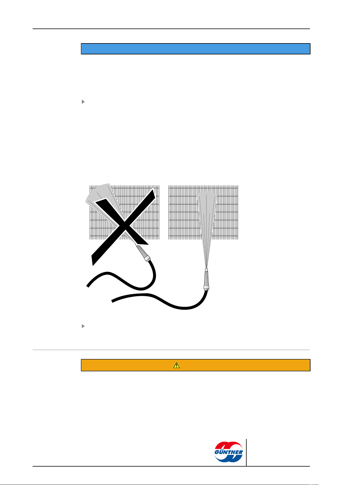
page 63 / 68
NOTICE
Danger of damage to property!
Water or steam jets can damage fans, electrical lines or other components.
•
Ensure that electrical connections and motors, as well as components and stored goods at the set-
up point are not touched by water or steam jets. Cover these if required.
Heavier moisture or greasy dirt must be removed with a high-pressure water jet (max. 50 bar
pressure), steam pressure jet (max. 50 bar pressure), min. 200 mm distance with flat jet nozzle,
or using neutral cleaning agent where applicable, always against the airflow direction. Ensure
here:
– With oily and greasy dirt it helps to add a cleaning agent to the water.
– When applying chemical agents ensure that they are not aggressive towards the unit's mate-
rials. Rinse the unit off after the treatment.
– Cleaning should be done from inside to the outside (but always opposing the dirt onset) and
from top to bottom, so that the dirt can be removed without returning.
– Hold the jet of the cleaner vertical to the fins (heat exchanger – max. deviation of ±5 de-
grees) to prevent fins from bending.
Continue cleaning until all dirt has been removed.
10.4.3 Cleaning fans
Danger of cutting off, pulling in!
There is a danger of cutting off fingers on the rotating fan blades, injury hazard for the hands and pulling
in danger for loose elements such as hair, necklaces or clothing parts.
CXGDF.1 | 2015-12
WARNING
© Güntner GmbH & Co. KG
Page 64

page 64 / 68
•
Power off the unit before you begin maintenance work. Secure the unit against unintentional switch-
ing on again by removing the electric fuses for the unit. Secure the unit with a suitable warning sign
referring to unintentional switching on.
•
Put fans , removable and hinged drip trays, the easy to open side covers, and guard grilles that
were removed or opened for maintenance back into their original status without fail before you put
the unit back into operation!
Dirt build-ups and frost and/or icing on the fans and the fan guard grilles must be removed regularly, otherwise they will cause imbalances or destruction and power losses. The fan motors themselves are maintenance-free.
Power off the unit and secure it against unintentional switching on.
Clean fans with one of the following procedures:
NOTE! Danger of damage to property! Mechanical cleaning with hard objects (e.g. steel
brushes, screw drivers, or similar) damages the fan. Forbidden!
– Cleaning with compressed air: Blow fans with compressed air (max. 10 bar pressure; min.
distance 200 mm) to remove dirt and contaminants. Continue cleaning until all dirt has been
removed.
– Cleaning with compressed air and brushes: Remove dry dust or dirt with a brush, a hand
brush or with compressed air (max. 10 bar pressure, min. distance of 200 mm) or with a
powerful industrial vacuum cleaner. Ensure here: use soft brushes (no steel brushes or similar)! Continue cleaning until all dirt has been removed.
Mount guard grille
Switch unit on
Note for the easy to open side covers and the removable and hinged drip trays.
With units with easy to open side covers and the removable and hinged drip trays these should be
opened or removed for better cleaning. The motors must, however, also be protected here from being sprayed.
After cleaning the easy to open side covers and the removable and hinged drip trays must be put
back to their original position and fixed and secured here against unintentional or unauthorised
opening.
10.5 Defrosting the unit
10.5.1 Notes on defrosting
WARNING
Warning against personal injury and damage to property!
Danger of falling unit parts, masses of water or ice when the drip tray is flapped out.
Nobody is allowed to be in the danger area below the unit during cleaning or maintenance work. The
drip tray can be flapped down for cleaning and is protected from falling down by a safety catch. Unit
parts, masses of water or ice can nonetheless fall down when it is flapped down.
CXGDF.1 | 2015-12
© Güntner GmbH & Co. KG
Page 65

page 65 / 68
Defrosting the unit at the correct times guarantees continuous operational reliability and the prevention of inaccessibilities that could result in a shutdown and disruptions. As the local conditions have
a very big influence of the unit's performance and the need for defrosting, the operation must be
checked regularly and specifically for frost and/or icing on the heat exchanger. The following notes
apply for defrosting the unit:
•
Regularly check for frost and/or icing. With a frost thickness of max. 1 mm per fin side the unit
must be defrosted to be able to guarantee fault-free operation.
•
Defrosting process must start in good time.
The defrosting frequency depends on the effects of penetrating moisture (e.g. cold storage room
door) or introduced moisture (e.g. goods to be cooled, .). It must be noted here that the temperature difference between the working fluid and the air inlet temperature is critical for the defrosting
frequency:
•
Unit with greater temperature difference: Frequent defrosting
•
Unit with lesser temperature difference: Less defrosting
Alternating operating states, e.g. usage changes at the set-up point, must also be considered. The
defrosting frequency can be influenced by effects on the air side. Insufficient unit-wall distance, distance between two opposing units too low, underdraughts shortly before the air outlet, incorrect
goods storage (too high, no wall distance, across the airflow direction) cause increased defrosting
frequency.
Defrosting completeness
When finishing the defrosting process you must ensure that the defrosting is absolutely complete.
Selecting the right defrosting temperature is an important requirement in this respect.
•
If the defrosting temperature is set too low this impairs the unit's effectiveness from one defrost-
ing to another with the removal of "ice-spots".
•
If the defrosting temperature is set too high this causes extreme water vapour formation, which
causes frost and ice to form around the unit.
Settling time
A period (approx. 5 to 8 minutes) between when the defrosting finishes and when the unit is activated has been proven to be necessary, as the unit's heat exchanger can drip off completely and the
defrosting water can flow away through the drip water tray drain during this period.
Delayed fan start
If the fans' activation is delayed by a further period (approx. 3 to 5 minutes), then the defrosting
heat from the heat exchanger is absorbed and it is not given off into the room as warm-moist air.
10.5.2 Defrost control
•
The defrosting process is started at pre-set intervals or as required.
•
The process completion must be ensured twice (time/temperature and temperature/tempera-
ture),
•
For defrost operation (circulation air, electric) the correct on-site installation of the defrosting
sensor must be ensured. See defrosting procedure listed below.
•
Recommendation – perform the defrosting process at the following times:
CXGDF.1 | 2015-12
© Güntner GmbH & Co. KG
Page 66

Electric defrosting (optional)
Cold operation X
Suction operation X
Defrost operation X
Drip phase X
Freeze on phase X
Cold operation X
Fans Operation Operation Off Off Off Operation
The duration of the individual phases depends from a variety of factors (e.g. temperature, moisture,
etc.) in the particular application.
10.5.3 Circulation air defrosting
With operation of the units at room temperatures in the plus range (plus-cold storage rooms) and
evaporation temperatures t0 = 0 to -5°C, circulation air defrosting is usually sufficient: with shut-off
working fluid-carrying lines the required defrosting heat is generated by the fan heat flow and the air
temperature in the plus range. But it also applies here: the refrigerating operation may be restarted,
as described, only after complete defrosting.
page 66 / 68
10.5.4 Electric defrosting (optional)
CXGDF.1 | 2015-12
With several units per room with electric defrosting alternating defrosting should be avoided, as otherwise reciprocal influences can have a negative effect here. These influences result on one hand
from the extraction of the heat from the units to be defrosted and therefore in a defrost delay, and
on the other hand in an additional stress with heat and moist air on the units in refrigerating operation. Group defrosting is recommended instead of alternating. Several units are grouped here into
a defrosting group. If a group is now defrosted, the other groups must be switched off. This means
that with a temperature increase in the room, which is not above the alternating defrosting one, the
reciprocal influencing of the units is limited to a minimum, as described above.
The following must be ensured here: With alternating defrosting within a room (group defrosting),
use defrost closure devices (defrost flaps, textile closure devices)! An on-site monitoring with a
safety device (temperature limiter; to be planned for in creating the annex) must be provided in acc.
with EN 60519-2; VDE 0721; T. 411 to rule out the danger of the units overheating. Operation without a temperature monitor is forbidden! The max. permissible fuse for the electric heating groups
© Güntner GmbH & Co. KG
Page 67

with 20 A must be complied with without fail. The min. fusing is provided in the order-related connection diagrams. To prevent the permissible pressure in the unit from being exceeded with electric
defrosting systems, in acc. with EN 378-2 either working fluid displacement must be enabled or a
suction circuit must be provided.
10.5.5 Further notes on defrosting
The drains of the drip trays must be heated (apart from plus-cold storage rooms), so that ice formation is prevented here.
page 67 / 68
CXGDF.1 | 2015-12
© Güntner GmbH & Co. KG
Page 68

page 68 / 68
11 Plans/diagrams
11.1 Electrics documentation
11.1.1 Fan motor connection diagram
11.1.2 Connection diagram electrical defrost (selectable option; accessory on customer request)
See motor terminal box cover inside on the fan.
See order-related offer documents
CXGDF.1 | 2015-12
© Güntner GmbH & Co. KG
 Loading...