

Page 1
Profi 2500
#
9413
1
D GB F DK
CZ SK
NL
I
NOR S
Güde GmbH & Co. KG
Birkichstraße 6
D-74549 Wolpertshausen
www.guede.com
Güde Scandinavia A/S
Engelsholmvej 33
DK-8900 Randers
www.guede.com
GÜDE Slovakia s.r.o
Podtúre!-Rove! 208
SK-033 01 Liptovský Hrádok
www.guede.com
Güde Hungary Kft.
Kossuth L. út 72
H-8420 Zirc
www.guede.com
Güde Czech, s.r.o.
Po"ernická 120
CZ-36005 Karlovy Vary
www.guede.com
Page 2
GB
2
List of Contents
Description Page
1. Parts Description ......................................................................................................................................2
2. Technical Data ......................................................................................................................................... 2
3. General Safety Precautions .....................................................................................................................3
3. Assembly..................................................................................................................................................5
4. Grinding Disk Check................................................................................................................................. 6
5. Grinding Disk Assembly ........................................................................................................................... 6
6. Clamping Screw Set Up ........................................................................................................................... 7
7. Grinding.................................................................................................................................................... 7
8. Grinding Depth Delimiter..........................................................................................................................8
10. Dimensions............................................................................................................................................... 9
9. Assembly Drawing.................................................................................................................................. 10
10. List of Spare Parts..................................................................................................................................11
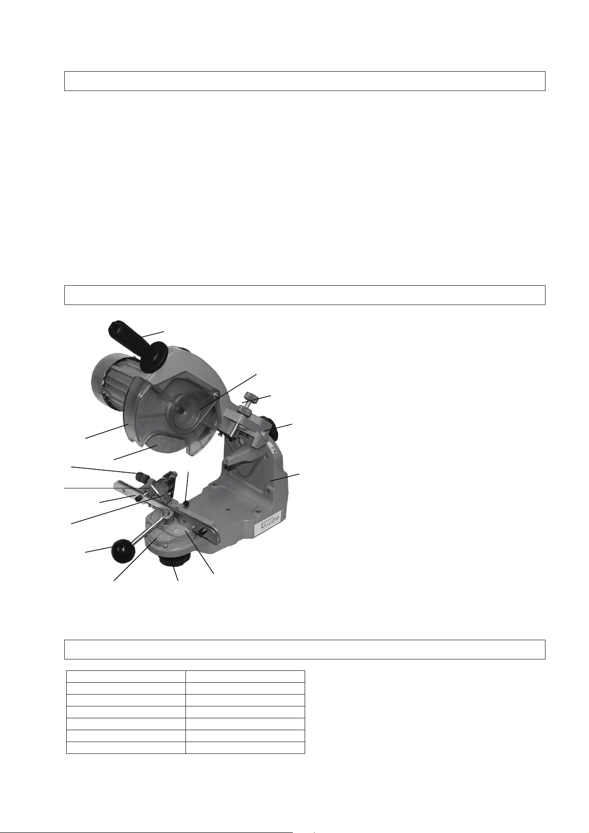
1. Parts Description
2. Technical Data
Profi 2500
Supply voltage:
230 Volt/50 Hz
Motor input power:
P1 230 Watt
Maximum speed:
3400 rpm
Noise level:
< 70 dB (A)
Weight:
ca. 5,8 kg
Product No.: 94131
1
2
3
4
5
16
15
10
8
6
7
9
12
13
14
11
1. handpiece
2. grinding disk lateral guard
3. depth of grind set screw
4. cutting edge angle set-up wheel
5. base
6. screw clamp cradle
7. cutting angle setting wheel
8. scale
9. clamping lever
10. mean distance set screw
11. guide flap valve
12. screw clamp
13. guide position set screw
14. setting screw
15. grinding disk
16. grinding disk protective enclosure
Page 3

GB
3
3. General Safety Precautions
Read the instruction manual carefully before the first use of the machine. If any doubt regarding the
connection and operation of the machine arises, seek the manufacturer’s assistance (servicing department)
Protect the machine from moisture, rain and dust.
FOR US TO SECURE THE HIGHEST DEGREE OF SAFETY, CONFORM TO THE FOLLOWING
INSTRUCTIONS:
- Use the machine only for the scope of work it has been designed for !
- When using the saw-chain grinder outdoor, you should always use a weather resistant extension cable
to connect it of a minimum diameter of 1.5 mm2 with the splash-proof plug and socket.
- The noise level in the working area is above 85 dB (A). Therefore, wear ear protection – hearing loss is
imminent!
- To protect your health at a grinding job, always use a dust protection mask and protective goggles!
- Always unplug the machine before any work on the machine (cleaning, grinding disk replacement etc.)
- Take care to have the saw-chain to be ground secured as appropriate for it not to slip out.
- It is your own interest to keep your machine clean at any time and after you finish a grinding job, check
the machine for damage.
- Always keep your saw-chain grinding machine clean. .
- Do not use any caustic to clean the plastic parts.
- Do not use the machine and do not work on it in proximity of inflammable liquids and vapours thereof. .
- Unplug the machine any time you replace a part or clean the machine.
- Protect the power cable from any damage the cable may be damaged by oil or acid.
- Important notice! Observe any national safety regulations regarding installation, operation and
maintenance .
- Upon having completed the job, unplug the saw-chain grinding machine from the mains.
- Protect your yes and colleagues from jumping particle and chips.
- Working gloves will protect your fingers and skin from cutting injuries.
- Always carry the power cable to the machine from behind.
- Store the machine in a place inaccessible to children.
- Always hold the machine with both the hands when working and mind safe footing and posture.
CAUTION!
Abide by the essential safety measures of protection from electric shock, accident and fire prevention.
Read all these instructions before you get down to the use of the electric machine and follow them. Keep
the safety instructions at a safe place for future reference .
Safe Work
- Keep your workplace tidy.
A messy work place may cause an accident.
- Always make allowances for the environmental effects. Do not expose the electric tools to rain. Do not
use them in moist or wet areas. Take care of sufficient lighting. Do not use them in proximity of
flammable liquids or gases.
- Get protected from electrical shock. Avoid any bodily contact with grounded objects (such as pipes,
radiators, stoves and refrigerators).
- Prevent the children from access.
Do not let other person to touch the machine or the cable. Prevent any unauthorised persons from
access to the working area.
- Store the machine at a safe place. When off the use, the machine should be kept at a dry, elevated
locked place out of the reach of children.
- Do not overload the machine.
Work better and in a safer manner within the scope of capacity as given.
- Use the correct machine. Do not use a machine of lower capacity for heavy jobs. Do not use the
machine for any purpose it has not been intended for. Only use the machine for the purposes
described in the instruction manual!
Page 4

GB
4
- Wear proper working clothing!
Do not wear any wide garments and jewellery that might be caught by the moving machine parts. For
working outdoors, rubber gloves and non-skid shoes are recommended. If your hair id long, wear a
hairnet. Use protective goggles.
- Wear a breathing mask when engaged in a dust-producing job.
- Do not use the cable for any purpose it has not been designated for.
Do not use the cable for carrying or hanging of the machine. Do not use the cable to pull out the plug
from the socket. Protect the cable from excessive temperatures, oil, and sharp edges.
- Avoid any abnormal posture. Mind safe footing and keep balance at any time
- Take due care of your machine.
Abide by the maintenance and grinding disk replacement regulations.
Check the machine cable regularly and when it is found to be damaged, have it replaced by a skilled
electrician. Check the extension cables regularly and replace them if damaged.
Keep the handle dry, free of any dir, oil and grease.
- Unplug the machine, if it is out of use, prior to the maintenance and tools replacement, e.g. grinding
disk.
- Remove any spanners from the machine.
Before switching on, check to see that any wrenches and adjustment tools were removed.
- Avoid an unintended switching.
Use only permitted and properly marked extension cables for working outdoors.
- Be attentive. Mind what you are doing. Get down to a job only when feeling good. Never use the
machine when distracted.
- Check the machine for possible damages.
- Before using the machine, you should check any protection devices and any parts showing slight
damage to see that the function intended is perfect. Check to see that the moving parts move freely,
do not drag and are not damaged. Any parts should be installed properly to comply with the conditions
of the machine safe operation. Damage protection devices and parts should be repaired in a
recognised professional workshop and replace unless the instructions for use specify otherwise.
Damaged switched should be replaced by the customer service workshop. Do not use a machine
with a defective ON/OFF switch.
CAUTION!
Always connect the machine via fault current circuit breaker (FI). This machine is in compliance
with any respective safety provisions. Any repairs shall be done by professionally qualified
persons and only genuine spare parts should be used. The provision not being observed, the
operator is in a risk of injury.
Page 5

GB
5
3. Assembly
The saw-chain grinding machine is delivered pre-assembled.
One part consists of the base, on which the chain guide is
located. The other part is a bearing arm with the motor and
handgrip.
The assembly shall be performed with the machine
unplugged!
The machine design provides either for a desk installation or wall
mounting. When installing it on the desk, put the machine on the
edge of the desk to the stop (Fig. 1) and screw it to the desk
using the holes in the base.
When mounting on the wall, use the respective holes in the
vertical part of the base (here, a distance from the wall should be
kept or spacers should be used for the access to the rear set
screw to be preserved).
After the desk top installation, fit the arm in the base inserting the
pilot pin and securing it with a hexagonal screw (Fig.2)
Now, it is possible to fit a washer on the rear side screw and
screw the setting and screw the setting wheel on. (Fig. 3).
Screw the supporting arm control holder on the screw in the
grinding disk body (Fig.4)
Fit the grinding disk enclosure on using the supplied screws and
a respective wrench (Fig. 5).
Tip:
When mounting on the wall, take care to mount the machine
at a height of 120 – 130 cm from the floor to avoid working
at eye height!
To be able to install the disk, it is necessary to unscrew the
auxiliary flange (Fig. 6).
1
2
3
4
5 6
Page 6

GB
6
4. Grinding Disk Check
5. Grinding Disk Assembly
The grinding disk on the hub torque is 7 Nm. Where practicable, use a torque spanner. Now, the grinding
disk additional guard should be fitted on (Fig. 8).
Check the correct bottoming of the disk: in should not move across and lengthwise. Now, with the grinding
disk properly installed, a trial may be performed. Stand by the machine from the side and watch out for
anybody dwelling in the working area.
If the grinding disk is vibrating or shows otherwise incorrect run, promptly switch off and unplug the
machine before you attempt clearing the fault.
The machine has a zero voltage circuit breaker, which is disabled on outage and will prevent any restarting
of the machine after the power supply is restored.
Using the sharpening stone and a clamping plate, it is possible to sharpen the disk to obtain the required
profile. In this case, be careful at work.
To avoid injuries and accidents only fitting grinding disks free of any defects should be used.
Check the disk you are about to fit in for damages prior to the assembly.
It may be done by a simple sound test: Hold the disk so that a pencil may be put in the hole and the disk
may swing freely. (Fig. P).
Now, knock the disk edge with another pencil carefully.
The disk should give a clear high pitch sound!
If the disk sound damped or blank, it is defective.
It should not be used!
A deep or damped sound indicates damage by cracks
Or similar. !
Do not fit the disk on the hub by force.
The central bore diameter should not be changed.
Only use matching disks .
The smallest grinding disk diameter should not be below
100 mm!
Any adjusting works should not be done unless the machine
is switched off and unplugged.
No damaged disks should be used!
7 8
P
After you have removed the
ancillary flange, you can insert the
grinding disk in the body from
below. See that the ancillary
flange and the disk abut against
each other precisely.
(Fig. 7).
Do not tighten the screws too
much to avoid any damage to the
disk.
Page 7

GB
7
6. Clamping Screw Set Up
7. Grinding
Before the start of grinding, the chain should be
conducted between both the attachment guides
Now, the tooth to be sharpened first should be
taken against the stop. Watch out for the
sharpening angle to correspond to the guides
position. The type of the chain to be sharpened
should be determined using the sharpening
block provided or the table p.9. There, you can
find out the cutting thickness, angles and
dimensions.
Set the guides to the chain width using the set
screw u(A) so that it is firmly fixed in the
clamping screw by clamping lever control (B).
Set the feed by set screw (E).
On severely worn chains, the lateral position of
the chain guide should be secured with a set
screw (D).
Set the top plate angle by means of the set
screw (p.3, p. 5) and it may be also read on the
scale (F). The vice angle should be set up by set
screw (G).
G
B
A
D
E
F
Vrcholový !ezný úhel
(Top Plate Angle)
Úhel ost!í
(Vice Angle)
With the clamping screw adjusted and the vice
angle set up (Notice: RH and LH teeth to be
differentiated) and preset the top plate angle, lead
the grinding disk down to the tooth by soft pushing
the supporting strut. The grind depth may be set
by set screw (K).
With clamping lever loosen (B), the set screw is
being screwed or unscrewed (E) until the grinding
disk to sharpen will touch the tooth. During the
procedure, pull the chain to the guide (L) carefully.
(Notice. Wear gloves when performing the job!)
K
L
Page 8

GB
8
8. Grinding Depth Delimiter
Some types of saw-chains require that the clamping screw be tilted by 5° - 10° (cf. Table: space Tilt
angle).
Note the notches (Fig.9).
Now, the machine may be switched on and the saw-chain grinding may be started by a careful thrust
on the grinding disk. Adjust the pressure as necessary. Mark the start of grinding e.g. with a piece of
chalk and grind all the teeth in one direction, then turn the clamping screw (mind the angle) and grind
the teeth in opposite direction.
With warn chains, the lateral guide position (Fig.10, position M) shall be set for the grinding disk not
to touch the guide.
Avoid any strong thrust as the teeth might collide and the chain would wear and tear too fast.
Notice : Never grind any driven parts.
obr.9
M
10
Find out in Table (p.9) what is the size of the
depth delimiter back grinding.
Grinding the depth delimiter, the screw clamp
position shall always be 0°.
Set the supporting strut and holder at 90° (Fig.
F).
The grind depth may be set using set screw K.
Page 9

GB
9
10. Dimensions
Page 10

GB
10
9. Assembly Drawing
Page 11

GB
11
10. List of Spare Parts
Spare Part No. Spare Part No.
Produc
t No.
Versi
on
Positi
on
Description
Produc
t No.
Versi
on
Position
Description
94131 01 001 Swing arm 94131 01 048 screw
94131 01 002 Grinding disk enclosure body 94131 01 049 screw
94131 01 003 Lateral guard 94131 01 050 bolt
94131 01 004 Switch enclosure 94131 01 051 screw
94131 01 005 enclosure 94131 01 052 screw
94131 01 006 limiter 94131 01 053 nut
94131 01 007 grinding disk 94131 01 054 nut
94131 01 008 flange 94131 01 055 washer
94131 01 009 flange 94131 01 056 washer
94131 01 010 set screw 94131 01 057 Wide washer
94131 01 011 Counter-nut 94131 01 058 Plastic ring
94131 01 012 Plastic ring 94131 01 059 cone
94131 01 013 holder 94131 01 060 Pull-off stone
94131 01 014 coupling 94131 01 061 Sharpening block
94131 01 015 switch 94131 01 062 wrench
94131 01 016 motor 94131 01 063 wrench
94131 01 017 joint 94131 01 064 lamp 230V E14 15W
94131 01 018 axis 94131 01 065 condenser
94131 01 019 Clamping wheel 94131 01 066 cable
94131 01 020 spring 94131 01 067 Column action protection
94131 01 021 case
94131 01 022 Base plate
94131 01 023 Swing support
94131 01 024 Clamping rod
94131 01 025 set screw
94131 01 026 Wide washer
94131 01 027 spring
94131 01 028 Small thrust spring
94131 01 029 Axial bolt
94131 01 030 Clamping lever rod
94131 01 031 Ball holder
94131 01 032 Chain support
94131 01 033 Case
94131 01 034 Connecting catch driver
94131 01 035 chain drive
94131 01 036 Counter nut
94131 01 037 Limiting spring
94131 01 038 spring
94131 01 039 Threaded pin
94131 01 040 case
94131 01 041 Plastic ring
94131 01 042 Hand wheel
94131 01 043 scale
94131 01 044 scale
94131 01 045 scale
94131 01 046 screw
94131 01 047 screw
Page 12

GB
12
EG-Konformitätserklärung
EC Declaration of Conformity
Hiermit erklären wir, Güde GmbH & Co. KG
We herewith declare, Birkichstraße 6, 74549 Wolpertshausen, Germany
Dass die nachfolgend bezeichneten Geräte aufgrund ihrer Konzipierung und Bauart
sowie in der von uns in Verkehr gebrachten Ausführungen den einschlägigen,
grundlegenden Sicherheits- und Gesundheitsanforderungen der EG-Richtlinien
entsprechen.
That the following Appliance complies with the appropriate basic safety and health requirements
of the EC Directive based on its design and type, as brought into circulation by us.
Bei einer nicht mit uns abgestimmten Änderung der Geräte verliert diese
Erklärung ihre Gültigkeit.
In a case of alternation of the machine, not agreed upon by us, this declaration will loose its
validity.
Bezeichnung der Geräte: - Profi 2500
Machine desciption:
Artikel-Nr.: - 94131
Article-No.:
Einschlägige EG-Richtlinien: - EG-Maschinenrichtlinie 98/37/EG
Applicable EC Directives: - EG-Niederspannungsrichtlinie 73/23/EWG
- EG-Richtlinie Elektromagnetische
Verträglichkeit 89/336/EWG mit Änderungen
-
Angewandte harmonisierte
Normen: - EN 61029-2-4/A1:2003
Applicable harmonized - EN 55014-1/A2:2002
Standard: - EN 55014-2/A1:2001
- EN 61000-3-2:2000
- EN 61000-3-3/A1:2001
Datum/Herstellerunterschrift: 23.07.2007
Date/Authorized Signature:
Angaben zum Unterzeichner: Mr. Arnold, executive officer
Title of Signatory:
 Loading...