

Gude Expert Power Control 1292, Expert Power Control 1202, 8801 User Manual

Manual
Expert Power Control 1202
Expert Power Control 1292
© 2018 Gude Analog- und
Digitalsysteme GmbH
Manual Ver. 2.4.3
from Firmware Ver. 1.6

2
Expert Power Control 1202/1292 © 2018 Gude Analog- und Digitalsysteme GmbH

3
Expert Power Control 1202/1292 © 2018 Gude Analog- und Digitalsysteme GmbH
Table of contents
1. Device Description 6
1.1 Security Advice ....................................................................................................... 7
1.2 Content of Delivery ................................................................................................. 7
1.3 Description ............................................................................................................. 7
1.4 Installation ............................................................................................................. 9
1.5 Overvoltage Protection ......................................................................................... 10
1.6 Technical Specifications ........................................................................................ 11
1.6.1 Electrical Measurement ......................................................................................... 12
1.7 Sensor .................................................................................................................. 12
2. Operating 14
2.1 Operating the device directly ................................................................................ 15
2.2 Control Panel ........................................................................................................ 15
2.3 Maintenance ........................................................................................................ 17
2.3.1 Maintenance Page ................................................................................................. 18
2.3.2 Configuration Management .................................................................................. 19
2.3.3 Bootloader Activation ............................................................................................ 21
2.4 GSM ..................................................................................................................... 22
2.4.1 SMS ........................................................................................................................ 24
2.4.1.1
SMS Commands ............................................................................................... 24
2.4.1.1.1 Powerport: Query Power Port State ........................................................... 24
2.4.1.1.2 Powerport: Simple Switching ...................................................................... 24
2.4.1.1.3 Powerport: Advanced Switching (Batchmode) ........................................... 25
2.4.1.1.4 Powerport: Advanced Switching (coldstart) ............................................... 25
2.4.1.1.5 Configuration: Read .................................................................................... 26
2.4.1.1.6 Configuration: Write ................................................................................... 26
2.4.1.1.7 Configuration: All Parameter ...................................................................... 27
2.4.1.1.8 Sensors: Query State ................................................................................... 28
2.4.1.1.9 Query Device State ...................................................................................... 28
2.4.1.2
SMS replies ...................................................................................................... 28
2.4.1.2.1 SMS command replies ................................................................................. 28
2.4.1.2.2 Status Change Report SMS ......................................................................... 29
2.4.2 Voice Call ................................................................................................................ 30
2.4.2.1
Menu ................................................................................................................ 30
2.4.2.1.1 Power Port Menu ........................................................................................ 31
2.4.2.1.2 Status Menu ................................................................................................ 32
2.4.2.1.3 Parameter Description ................................................................................ 32
2.4.3 Power Port Commands .......................................................................................... 33
2.4.4 Security .................................................................................................................. 35
3. Configuration 36
3.1 Power Ports .......................................................................................................... 37

4
Expert Power Control 1202/1292 © 2018 Gude Analog- und Digitalsysteme GmbH
Table of contents
3.1.1 Watchdog ............................................................................................................... 38
3.2 Ethernet ............................................................................................................... 39
3.2.1 IP Address ............................................................................................................... 40
3.2.2 IP ACL ..................................................................................................................... 41
3.2.3 HTTP ....................................................................................................................... 42
3.3 Protocols .............................................................................................................. 43
3.3.1 Console ................................................................................................................... 43
3.3.2 Syslog ..................................................................................................................... 44
3.3.3 SNMP ...................................................................................................................... 44
3.3.4 Radius ..................................................................................................................... 46
3.3.5 Modbus TCP ........................................................................................................... 47
3.4 Sensors ................................................................................................................. 48
3.4.1 Port Switching ........................................................................................................ 49
3.5 E-Mail ................................................................................................................... 50
3.6 Front Panel ........................................................................................................... 51
3.7 GSM ..................................................................................................................... 51
3.7.1 GSM General .......................................................................................................... 52
3.7.2 GSM Misc ............................................................................................................... 53
3.7.3 GSM Phonebook .................................................................................................... 54
3.7.4 GSM SIM Card ........................................................................................................ 54
3.7.5 GSM Provider ......................................................................................................... 54
4. Specifications 56
4.1 IP ACL ................................................................................................................... 57
4.2 IPv6 ...................................................................................................................... 57
4.3 Radius ................................................................................................................... 58
4.4 Automated Access ................................................................................................ 58
4.5 SNMP ................................................................................................................... 59
4.5.1 Device MIB 1202 .................................................................................................... 61
4.5.2 Device MIB 1292 .................................................................................................... 63
4.6 SSL ........................................................................................................................ 64
4.7 Console ................................................................................................................. 67
4.7.1 Console Cmd 1202 ................................................................................................. 69
4.7.2 Console Cmd 1292 ................................................................................................. 75
4.8 Modbus TCP ......................................................................................................... 82
4.9 Messages .............................................................................................................. 86
5. Support 88
5.1 Data Security ........................................................................................................ 89
5.2 Contact ................................................................................................................. 89
5.3 Declaration of Conformity ..................................................................................... 90

5
Expert Power Control 1202/1292 © 2018 Gude Analog- und Digitalsysteme GmbH
Table of contents
5.4 FAQ ...................................................................................................................... 90
91
Index

Device Description

7
Expert Power Control 1202/1292 © 2018 Gude Analog- und Digitalsysteme GmbH
Device Description
1 Device Description
1.1 Security Advice
· The device must be installed only by qualified personnel according to the following
installation and operating instructions.
· The manufacturer does not accept responsibility in case of improper use of the
device and particularly any use of equipment that may cause personal injury or material damage.
· The device contains no user-maintenable parts. All maintenance has to be performed by factory trained service personnel.
· This device contains potentially hazardous voltages and should not be opened or
disassembled.
· The device can be connected only to 230V AC (50Hz or 60 Hz) power supply sockets.
· The power cords, plugs and sockets have to be in good condition. Always connect
the device to properly grounded power sockets.
· The device is intended for indoor use only. Do NOT install them in an area where excessive moisture or heat is present.
· Because of safety and approval issues it is not allowed to modify the device without
our permission.
· The device is NOT a toy. It has to be used or stored out or range of children.
· Care about packaging material. Plastics has to be stored out of range of children.
Please recycle the packaging materials.
· In case of further questions, about installation, operation or usage of the device,
which are not clear after reading the manual, please do not hesitate to ask our support team.
· Please, never leave connected equipment unattended, that can cause damage.
· Connect only electrical devices that do not have limited on-time. I.e. in case of fail-
ure, all connected appliances have to cope with a continuous on-time without causing damage.
1.2 Content of Delivery
The package includes:
· Expert Power Control 1202 / 1292
· GSM Antenna (only EPC 1292)
· Quick Start Guide
· CD-ROM with Manual and Softwaretools
1.3 Description
The Expert Power Control 1202 / 1292 can switch 4 different load outputs. The
device has the following features:
· 4 Power Ports individually switchable directly on the device, via HTTP(S), SNMP
· Case allows mounting in 19 inch racks

8
Expert Power Control 1202/1292 © 2018 Gude Analog- und Digitalsysteme GmbH
Device Description
· Status and Power-up delay (0...9999 seconds) adjustable individually for each Power
Port after power blackout
· Simultaneous power-up of multiple Power Ports prevented by latency time of 1
second
· Programmable turn-on/turn-off sequence
· 4-channel watchdog, an individual watchdog (ICMP/TCP) can be assigned for each
Power Port
· Metering of energy, current, power factor, phase angle, frequency, voltage and active/apparent/reactive power
· Two energy meters, one meters continously, the other energy meter is resettable
· A clearly visible LED display on the device reveals total current, IP address, sensor
data and error reports
· Interface for optional sensors for environmental monitoring (temperature and humidity)
· Integrated overvoltage protection prevents damage of device and of connected consumers (L-N 10 kA)
· Dedicated high-inrush relays avoid welding of relay contacts at start-up peaks
· Firmware update via Ethernet during operation
· Comfortable configuration by web browser, Windows or Linux tool
· Generation of messages (e-mail, Syslog and SNMP traps) and relay switching de-
pending on the energy measurement limits, resp. external sensors
· IPv6 ready
· HTTP/HTTPS, e-mail (SSL, STARTTLS), DHCP, Syslog
· SNMPv1, v2c, v3 (Get/Traps)
· Modbus TCP Support
· Console Commands with telnet support and serial interface.
· TLS 1.0, 1.1, 1.2
· IP Access Control List
· Secure login over SSL
· Low internal power consumption
· Developed and manufactured in Germany
Only Expert Power Control 1292:
· 4 Power Ports individually switchable via voicecall, SMS and Datacall
· GSM admin and user access for all Power Ports definable
· For pre-paid and post-paid SIM cards (SIM card not included)
· Triband network
· FreeCall: Predefined action upon toll-free incoming call from a specific number
9
Expert Power Control 1202/1292 © 2018 Gude Analog- und Digitalsysteme GmbH
Device Description
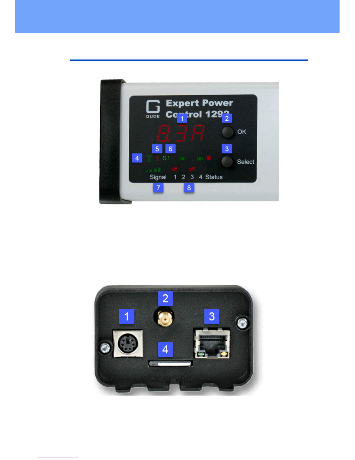
1.4 Installation
1. Actual Current (7-segment display)
2. OK Button
3. Select Button
4. Signal Tower indicator LED for GSM Connection (only EPC 1292)
5. "Flash" LED Overvoltage Protection (red when inactive)
6. "S1" external sensor indicator
7. GSM signal strength (only EPC 1292)
8. 4 plain text displays (on/off) for the state of the Power Ports
1. Sensor connector
2. Antenna terminal (only EPC 1292)
3. Ethernet connector (RJ45)
4. SIM card slot (only EPC 1292)
10
Expert Power Control 1202/1292 © 2018 Gude Analog- und Digitalsysteme GmbH
Device Description
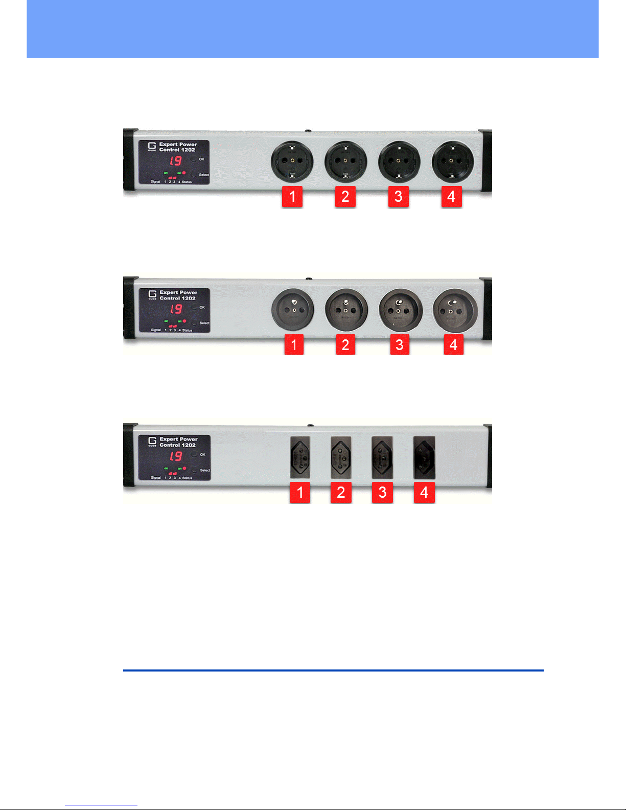
Power Ports 1 to 4 (Expert Power Control 1202-1 / 1292-1)
Power Ports 1 to 4 (Expert Power Control 1202-2 / 1292-2)
Power Ports 1 to 4 (Expert Power Control 1202-3 / 1292-3)
Start-up the device
· Connect the power cord of the unit to the mains supply.
· Plug the network cable into the Ethernet connector (RJ45).
· Attach the optional external sensor to the sensor connector.
1.5 Overvoltage Protection
The device contains an overvoltage protection. The protection is based on input side
varistors with thermal fuse between phase (L) and neutral (N) to protect the internal
electronics and power ports with failure detection (permanently triggered thermal fuse).
The state of the protection is indicated on the front panel by a red flash. A not visible
flash means, that the protection is active, a red flash symbolizes that the overvoltage

11
Expert Power Control 1202/1292 © 2018 Gude Analog- und Digitalsysteme GmbH
Device Description
protection fails. In addition, the status of the overvoltage protection can be seen on the
Webpage (HTTP) and acquired with SNMP. The surge protection module is designed
that it can derive a practical unlimited number of voltage pulses in normal installation
environments. In an environment with many energy rich surge pulses it can result in
permanent loss of function due to aging of the overvoltage protection element.
Recovering of the overvoltage protection function can only be performed by the
manufacturer of the device. In the normal case, the device will continue to work even
after the failure of the protective function.
A signaling via E-Mail, Syslog or SNMP trap occurs only once during operation, exactly at the moment in which the protection fails. In addition, at the start up of the
device a message is generated, when the overvoltage protection is not active.
1.6 Technical Specifications
Interfaces
(EPC 1202-1 / EPC 1292-1)
1 x Power supply (CEE 7/4 type F, max.16 A),
length approx 2m
4 x Load outputs (CEE 7/3 type F, max. 16 A)
1 x Ethernet port (RJ45)
1 x Mini-DIN for external sensor
(EPC 1202-2 / EPC 1292-2)
1 x Power supply (CEE 7/4 type E, max.16 A),
length approx 2m
4 x Load outputs (CEE 7/3 type E, max. 16 A)
1 x Ethernet port (RJ45)
1 x Mini-DIN for external sensor
(EPC 1202-3 / EPC 1292-3)
1 x Power supply (CEE 7/4 type J, max.10 A),
length approx 2m
4 x Load outputs (CEE 7/3 type J, max. 10 A)
1 x Ethernet port (RJ45)
1 x Mini-DIN for external sensor
Network connectivity
10/100 MBit/s 10baseT Ethernet
Protocols
TCP/IP, HTTP/HTTPS, SNMP v1/v2c/v3,
SNMP traps, Syslog, E-Mail (SMTP)
GSM Modem (only EPC 1292)
Triband GSM Module (900/1800/1900
MHz)
Sim Card (only EPC 1292)
Mini-SIM
Power Supply
internal power supply (90-265V AC / -15% /
+10%)
Overvoltage Protection
· maximum operating voltage
· single peak current for 20/80us pulse
· max. clamping voltage 20/80us pulse,
Ipk = 100 A
20 mm/190 J varistor disk
300 VACrms
10000 A
710 V
Environment
· Operating temperature
· Storage temperature
· Humidity
0°C - 50 °C
-20°C - 70 °C
0% - 95% (non-condensing)
Case
Synthetic
Measurements
484mm x 46mm x 74mm (L x H x W)
Weight
approx. 1050 g
12
Expert Power Control 1202/1292 © 2018 Gude Analog- und Digitalsysteme GmbH
Device Description
1.6.1
Electrical Measurement
typical fault tolerances for Ta=25°C, I=1Arms...16Arms, Un=90Vrms...265Vrms
Electrical Measurement Specification
Category
Range
Unit
Resolution
Inaccuracy
(typical)
Voltage
90-265
V
0.01
< 1%
Current
0 - 16
A
0.001
< 1.5%
Frequency
45-65
Hz
0.01
< 0.03%
Phase
-180 - +180
°
0.1
< 1%
Active power
0 - 4000
W1< 1.5%
Reactive power
0 - 4000
Var1< 1.5%
Apparent power
0 - 4000
VA1< 1.5%
Power factor
0 - 1-0.01
< 3%
Energy Counter
Active Energy
(total)
9.999.999,999
kWh
0.001
< 1.5%
Active Energy
(temporary)
9.999.999,999
kWh
0.001
< 1.5%
1.7 Sensor
One external sensor can be connected to the Expert Power Control 1202 / 1292.
The following sensors are currently available
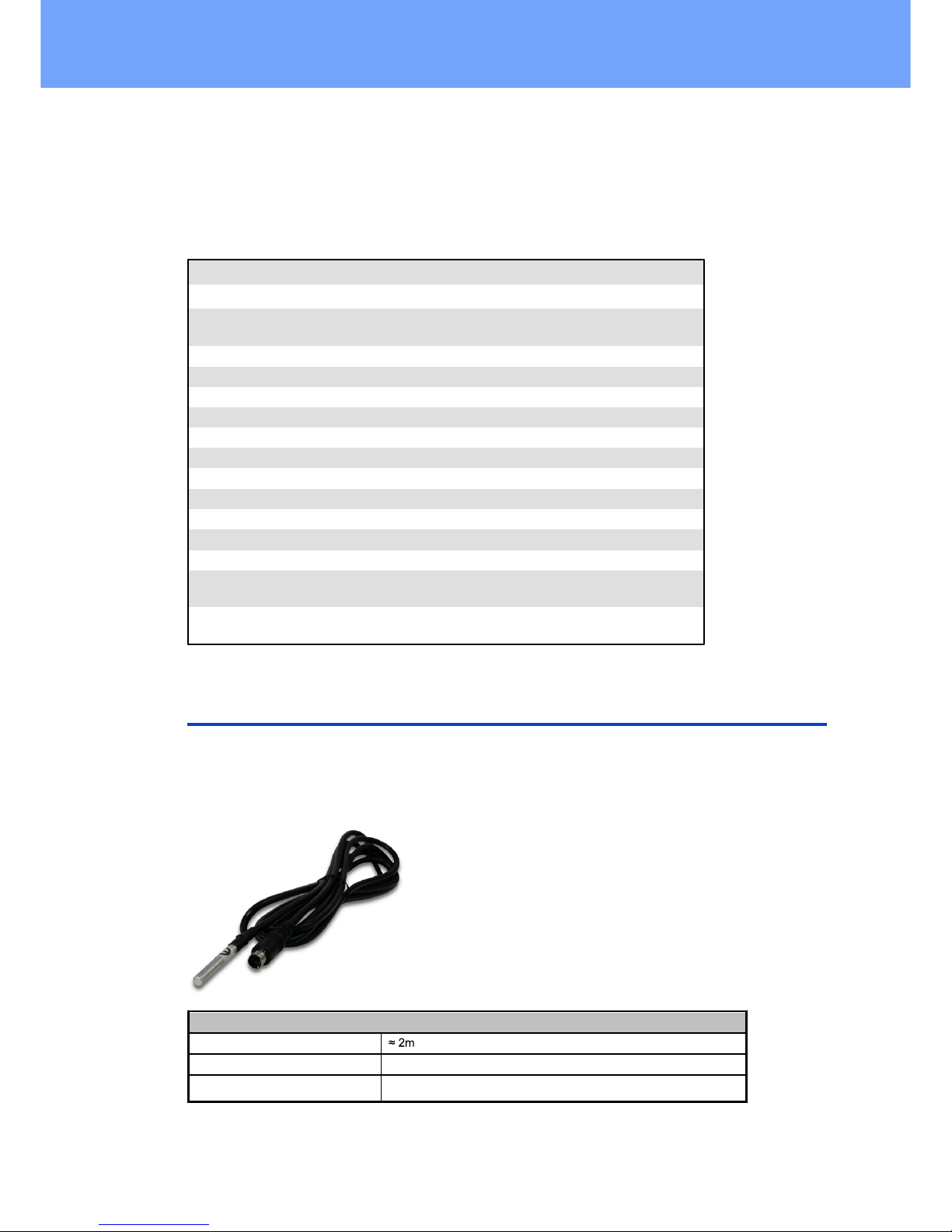
Temperature-Sensor 7001
Cable length
Connector
Mini-DIN
Measurement range
-20°C to +80°C at ±2°C (maximum) and ±1°C (typical)
13
Expert Power Control 1202/1292 © 2018 Gude Analog- und Digitalsysteme GmbH
Device Description
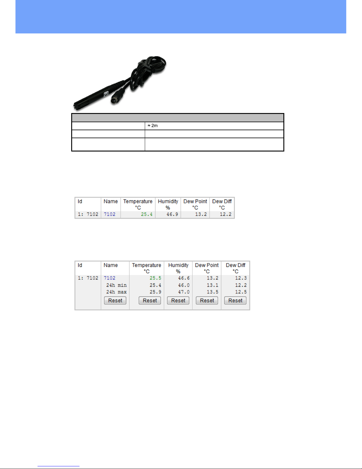
Humidity/Temperature-Sensor 7002
Cable length
Connector
Mini-DIN
Measurement range
Temp: -20 to +80°C, ±0,5°C (maximum) and ±0,3°C (typical)
Humidity: 0-100%, ±3% (maximum) and ±2% (typical)
The sensor is automatically detected after connect. This is indicated by the green "S1"
LED on the front panel. The sensor values are displayed at the "Control Panel" web
page:
A click on the link in the "Name" column opens the display of the Min and Max values.
The values in a column can be reset using the "Reset" button. The "Reset" button in
the name column deletes all stored Min and Max values.

Operating
15
Expert Power Control 1202/1292 © 2018 Gude Analog- und Digitalsysteme GmbH
Operating
2 Operating
2.1 Operating the device directly
Port Switching
The current status of the output is indicated by the color of the LED. Red indicates that
the output is off, green shows that the output is on. On the device are the buttons "select" and "ok". If you press "select", the LED will blink for the first output, ie the output is
selected. Press "select" again to select the next output. Hold down the button "ok" for
two seconds, then the status of the selected output is toggled.
Display Information
If no port is selected manually, repeatedly pressing the "ok" key will show the IP-address and the values of the external sensors on the display.
Status-LED
The Status LED shows the different states of the device:
· red: The device is not connected to the Ethernet.
· orange: The device is connected to the Ethernet and waits for data from the DHCP
server.
· green: The device is connected to the Ethernet and the TCP/IP settings are alloc-
ated.
· periodic blinking: The device is in Bootloader mode.
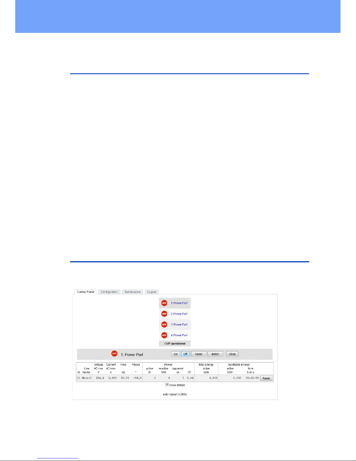
2.2 Control Panel
Access the web interface: http://"IP-address" and log-in.
The web page provides an overview of the switching state, energy measurement values, as well as the external sensors, provided that they are connected. When a single
16
Expert Power Control 1202/1292 © 2018 Gude Analog- und Digitalsysteme GmbH
Operating
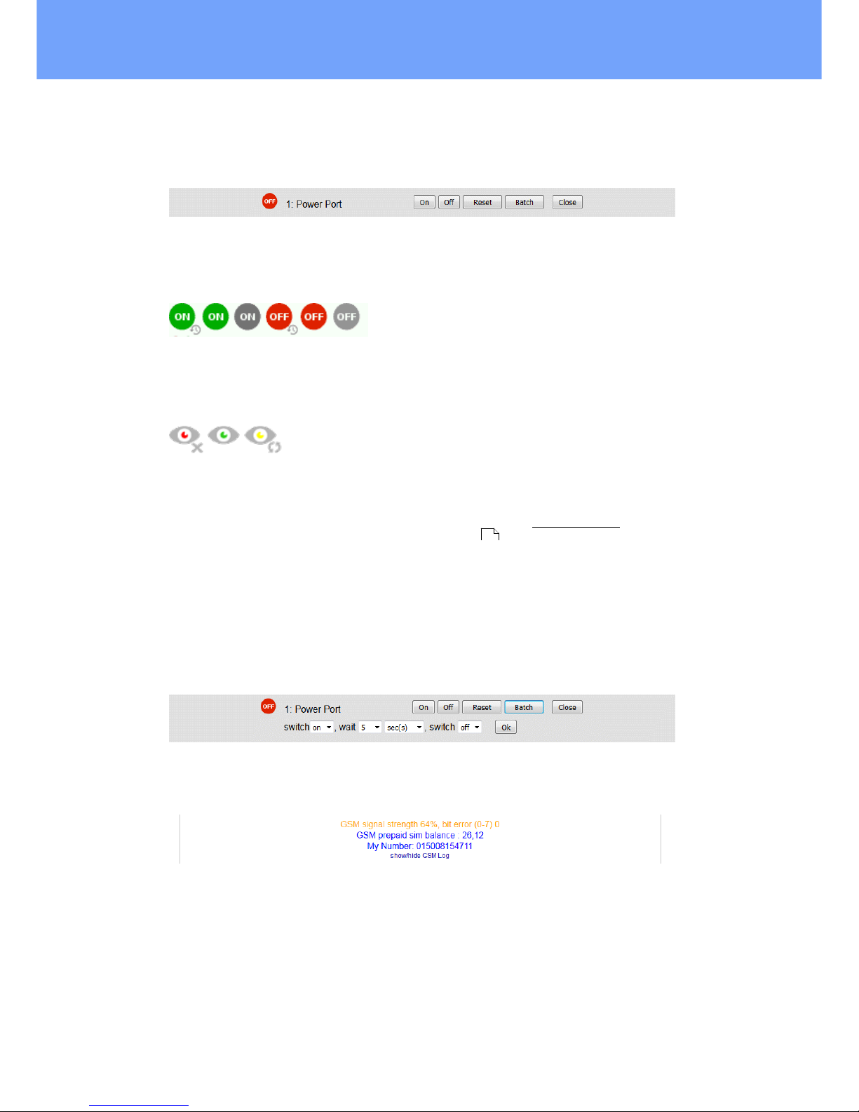
port is clicked at the Expert Power Control 1202 / 1292, a panel with buttons to control a single port appear:
The Port icon is green when the relay is closed, or red in the open state. An additional
small clock icon indicates that a timer is active. Timer can be activated by delay, reset
or batch mode.
An activated Watchdog is represented by an eye icon. An "X" means, that the address
that should be observed, could not be resolved. Two circular arrows show a booting
status.
The ports can be switched manually with the "On" and "Off" buttons. If the port is
turned on, it can be turned off by pressing the "Reset" button, until after a delay it turns
itself on again. The delay time is determined by the parameter Reset Duration, which is
described in the chapter "Configuration - Power Ports ". The "Close" button dissolves the panel again.
Batchmode
Each individual port can be set for a selectable period of time to the state "switch on"
or "switch off". After the selected time they are automatically switched to the second
preselected state.
Optionally the device can be switched via a Perl script or external tools like wget. More
information is available on our support wiki at www.gude.info/wiki.
For devices with a GSM module (Expert Power Control 1292), additional reception information, the prepaid credit and the own call number are displayed. An overview of
the GSM activities can be expanded.
37

17
Expert Power Control 1202/1292 © 2018 Gude Analog- und Digitalsysteme GmbH
Operating
2.3 Maintenance
The actual device generation with IPv6 and SSL allows all maintenance functions in
the web interface to be carried out on the Maintenance Page .
Maintenance in the web interface
The following functions are available from the maintenance web page:
· Firmware Update
· Change the SSL certificate
· Load and save the configuration
· Restart the device
· Factory Reset
· Jump into the Bootloader
· Delete the DNS cache
Upload Firmware, Certificate or Configuration
On the Maintenance Page , select the required file with "Browse .." in the sections
"Firmware Update", "SSL Certificate Upload" or "Config Import File Upload" and press
"Upload". The file is now transferred to the update area of the device and the contents
are checked. Only now, pressing the "Apply" button will permanently update the data,
or abort with "Cancel".
Only one upload function can be initiated with a reboot, eg. you cannot transmit
firmware and configuration at the same time.
If after a firmware update, the web page is not displayed correctly anymore, this
may be related to the interaction of Javascript with an outdated browser cache. If a
Ctrl-F5 does not help, it is recommended that you manually delete the cache in the
browser options. Alternatively, you can test start the browser in "private mode".
Actions in Bootloader mode
If the web interface of the device is no longer accessible, the device can be put into
Bootloader mode (see chapter Bootloader activation ). The following functions can
be executed using the GBL_Conf.exe application:
· Set IPv4 address, net-mask and gateway
· Turn HTTP password on and off
· Turn IP-ACL on and off
· Factory Reset
· Jump into the bootloader (can be switched on and off)
· Restart the device
For devices with relays, entering or exiting the bootloader mode does not change
the state of the relays as long as the operating voltage is maintained.
The GBL_Conf.exe program is available free of charge on our website www.gude.info
and can also be found on the enclosed CD-ROM.
18
18
21
18
Expert Power Control 1202/1292 © 2018 Gude Analog- und Digitalsysteme GmbH
Operating
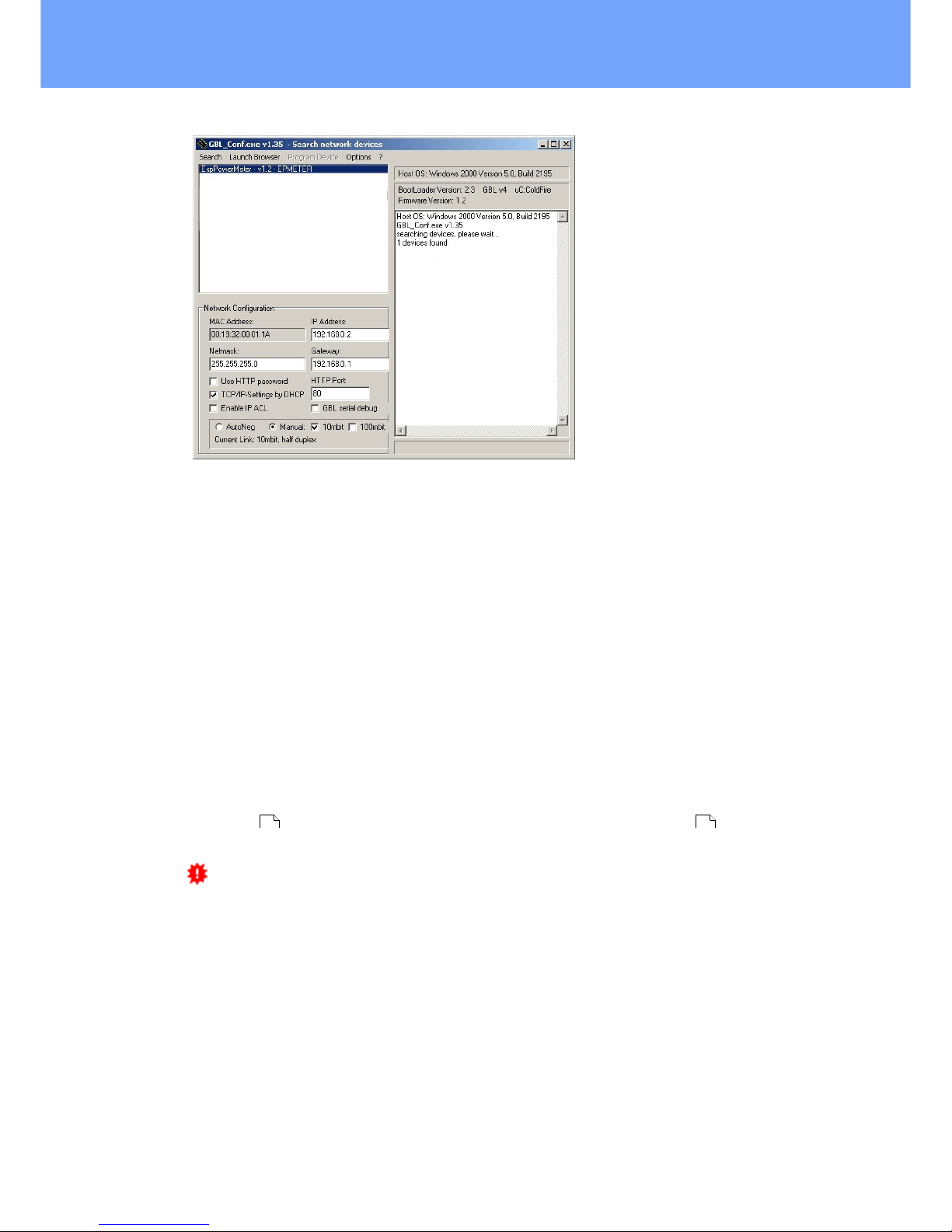
Interface GBL_Conf
To check the network settings with GBL_Conf.exe, start the program and choose "All
Devices" in the "Search" menu. From the list select the appropriate device. The lower
part of the left half of the window now shows the current network settings of the device.
If the IP address is displayed with the default settings (192.168.0.2), either no DHCP
server is present on the network, or there could be no free IP address assigned to it.
· Activate the Bootloader Mode (see Chapter Bootloader Mode) and choose in menu
"Search" the item "Bootloader-Mode Devices only"
· Enter the desired settings in the edit window and save them with "Save Config".
· Deactivate the boot loader mode for the changes to take effect. Select again "All
Devices" in the "Search" menu of GBL_Conf.exe.
The new network configuration is now displayed.
Factory Reset
The device can be reset to the factory default via the web interface from the Maintenance Page or from the Bootloader mode (see chapter Bootloader activation ). All
TCP/IP settings are reset in this operation.
If a unit is set to factory defaults, an uploaded certificate or updated firmware will
be preserved.
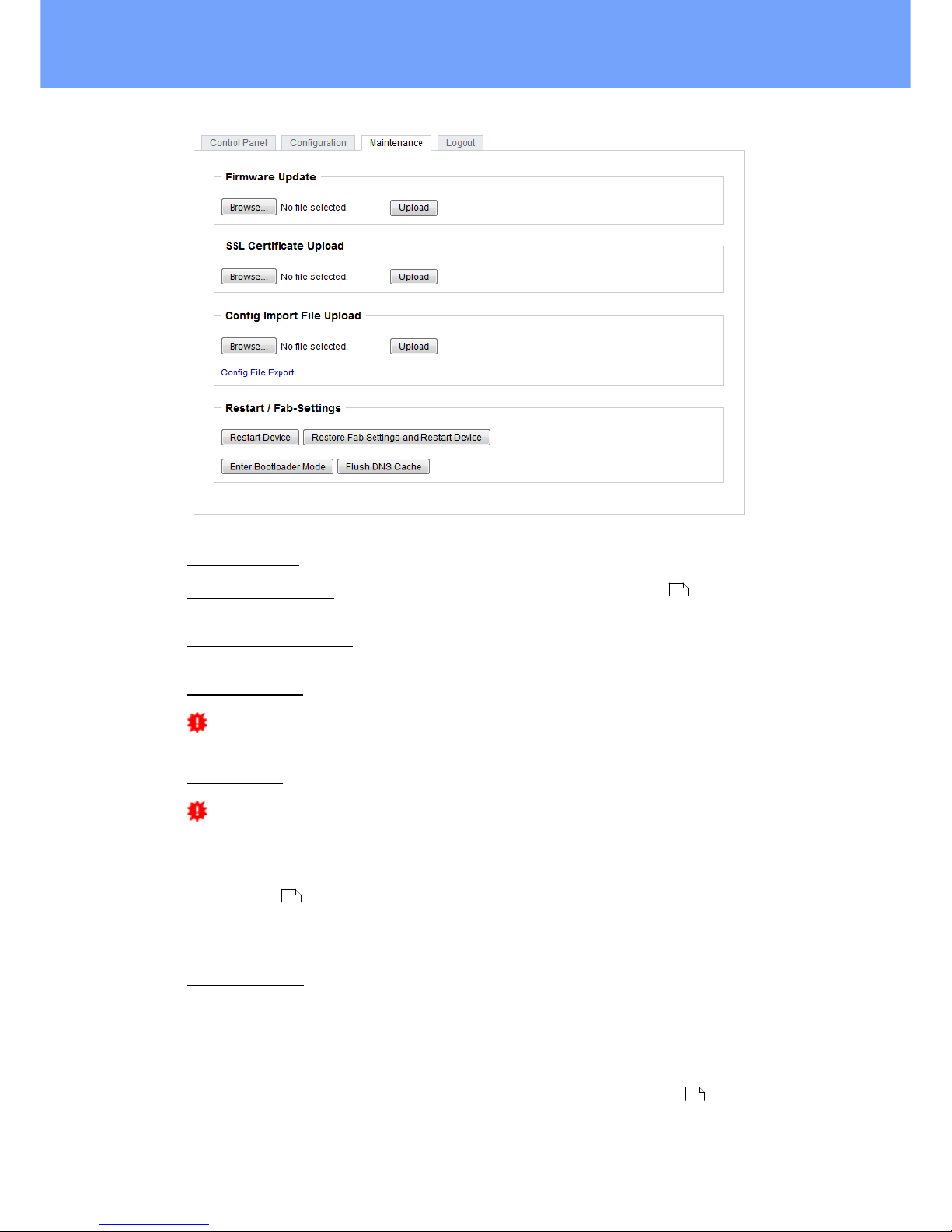
2.3.1
Maintenance Page
This section provides access to important functions such as Firmware Update or Restart Device. It is advisable to set an HTTP password for this reason.
18 21
19
Expert Power Control 1202/1292 © 2018 Gude Analog- und Digitalsysteme GmbH
Operating
Firmware Update: Start a firmware update.
SSL Certificate Upload: Saves your own SSL certificate. See chapter "SSL " for the
generation of a certificate in the right format.
Config Import File Upload: Loads a new configuration from a text file. To apply the new
configuration, a "Restart Device" must be executed after the "Upload".
Config File Export: Saves the current configuration in a text file.
Saving the configuration should only be carried out in an SSL connection, since it
contains sensitive password information (even if it is encrypted or hashed).
Restart Device: Restarts the device without changing the status of the relays.
Some functions such as a firmware update or changing of the IP-address and
HTTP settings require a restart of the device. A jump to the boot loader or a restart of
the device lead by no means to a change of the relay states.
Restore Fab Settings and Restart Device: Performs a restart and resets the device to
factory default .
Enter Bootloader Mode: Jumps into bootloader mode, where additional settings can be
made with GBL_Conf.exe.
Flush DNS Cache: All entries in the DNS cache are discarded and address resolutions
are requested again.
2.3.2
Configuration Management
The device configuration can be saved and restored in the maintenance area .
65
22
18

20
Expert Power Control 1202/1292 © 2018 Gude Analog- und Digitalsysteme GmbH
Operating
The "Config File Export" function can be used to save the current configuration as a
text file. The syntax used in the configuration file corresponds to the commands of the
Telnet console. If the configuration of a device is to be restored from a text file, load
the file with "Upload" and restart the device with "Restart Device".
Saving the configuration should only be carried out in an SSL connection, since it
contains sensitive password information (even if it is encrypted or hashed). For the
same reasons, it is advisable to carefully handle the generated configuration files when
archiving.
Editing the configuration file
It is possible to customize a saved configuration file with a text editor for your own
needs. For example, one scenario would be to use a script language to automate the
creation of many customized versions of a configuration, then equip a large number of
devices with an individualized configuration. Also Upload and restart with CGI commands can be done in scripting languages. With use of the comment sign "#" you can
quickly hide single commands or add personal notes.
If you modify a configuration file manually, it is not always clear which limits are allowed
for parameters. After uploading and restarting, commands with invalid parameters are
ignored. Therefore, the generated configuration includes comments describing the
boundaries of the parameters. Where "range:" refers to a numeric value, and "len:" to a
text parameter. E.g:
email auth set 0 #range: 0..2
email user set "" #len: 0..100
The command "system fabsettings" from the beginning of a generated configuration
file brings the device into the factory state, and then executes the individual commands
that modify the configuration state. It may be desirable to make the changes relative to
the current configuration, and not out of the factory state. Then the "system fabsettings" should be removed.
No output of default values
The configuration file contains (with exceptions) only values which differ from the default. The command "system fabsettings" (go to the factory state) from the beginning of
a generated configuration file should not be removed, otherwise the device can get incompletely configured.
Configuration via Telnet
The configuration files can in principle also be transferred in a Telnet session, but then
the settings are changed during operation, and not completely when restarting, as it
would have been the case with an upload. It can happen that events are triggered at
the same time as the device is configured. One should therefore:
a) disable the function
b) completely parametrize
c) reactivate the function

21
Expert Power Control 1202/1292 © 2018 Gude Analog- und Digitalsysteme GmbH
Operating
An example:
email enabled set 0
email sender set "" #len: 0..100
email recipient set "" #len: 0..100
email server set "" #len: 0..100
email port set 25
email security set 0 #range: 0..2
email auth set 0 #range: 0..2
email user set "" #len: 0..100
email passwd hash set "" #len: 0..100
email enabled set 1 #range: 0..1
2.3.3
Bootloader Activation
The configuration of the device from the application "GBL_Conf.exe" is only possible, if
the device is in Bootloader Mode.
Activation of the Bootloader Mode
1) via push button:
· Hold both buttons for 3 seconds
2) or
· Remove the power supply
· Hold down the "Select" button. If the push button is recessed, use a pin or paper clip
· Connect the operating voltage
3) by Software: (only if "Enable FW to BL" was previously activated in the
"GBL_Conf.exe" application)
· Start the "GBL_Conf.exe" program
· Do a network search with the "Search" menu action
· Activate in menu "Program Device" the item "Enter Bootloader"
4) via web interface:
Press "Enter Bootloader Mode" on the maintenance web page.
Whether the device is in Bootloader mode, is indicated by the flashing of the status
LED, or it is shown in "GBL_Conf.exe" application after a renewed device search (appendix "BOOT-LDR" after the device name). In Bootloader mode the program
"GBL_Conf.exe" can disable the password and the IP ACL, perform a firmware update,
and restore the factory settings.
For devices with relays, entering or exiting the bootloader mode does not change
the state of the relays as long as the operating voltage is maintained.
Abandonment of the Bootloader Mode
1) via push button:
· Hold both buttons for 3 seconds (only if the device has 2 buttons)
18

22
Expert Power Control 1202/1292 © 2018 Gude Analog- und Digitalsysteme GmbH
Operating
2) or
· Remove and connect the power supply without operating a button
3) by Software:
· Start the "GBL_Conf.exe" application
· Do a network search with the "Search" menu action
· In menu "Program Device" activate the item "Enter Firmware"
Factory Reset
If the device is in bootloader mode, it can always be put back to its factory default. All
TCP/IP settings are reset in this operation.
If a unit is set to factory defaults, an uploaded certificate or updated firmware will
be preserved.
1) via push button:
· Activate the Bootloader Mode of the device
· Hold down the button (or the "Select" button for devices with 2 buttons) for 6
seconds. If the push button is recessed, use a pin or paper clip
· The status LED will blink in a fast rhythm, please wait until the LED blinks slowly
(about 5 seconds)
2) by Software:
· Activate the Bootloader Mode of the device
· "Start the GBL_Conf.exe" program
· In menu "Program Device" activate the item "Reset to Fab Settings"
· The status LED will blink in a fast rhythm, please wait until the LED blinks slowly
(about 5 seconds)
2.4 GSM
To use the GSM functions, there must be an activated SIM card in the SIM card slot.
If the SIM card is inserted, and the device is enabled, the integrated GSM module
searches automatically for a connection to the GSM network. If this connection works,
you can control and configure the device via SMS or by call.
When operating via SMS, send defined SMS commands to the device. The device executes these commands and confirms them with reply SMS.
When operating via phone call, you can perform commands by FreeCall, that allow the
unit to perform preconfigured commands, when it is called from a particular phone
number. There is no connection established and there are no call charges. Another
possibility is the voice call. Here, the device menu is operated using DTMF codes. This
type of operation can also be carried out automatically.
Preparing for GSM operation
If you are using a new SIM card, please take note:

23
Expert Power Control 1202/1292 © 2018 Gude Analog- und Digitalsysteme GmbH
Operating
1. Preparing the SIM card
· If you are using a contracted SIM card, please start with step 2
· If you are using a prepaid SIM card, please take care:
o There has to be a positiv balance on the card
o The card has to be activated. New prepaid cards need some
manual operation at the start of usage. These requests have to be
made from a user with a cellphone.
2. SIM-card pin code
· The device awaits the SIM card pin code 1234 first. Enter this PIN to the
SIM card, by using a cellphone. In case you are using another pin code,
you have to configure the EPC NET GSM before you activate the GSM
part of the device! Otherwise this may lead to a lock of the SIM card.
· You can disable the need to enter the PIN code on the SIM card with a
mobile phone. In this case the EPC NET GSM accepts the SIM card
without checking the code.
3. Install SIM card
· Switch off the device or deactivate the GSM module. Alternatively, you
can just turn off the GSM module in the EPC NET GSM via software.
Never install a SIM card, when GSM module is active. Otherwise the
SIM card may be destroyed.
· Insert the SIM card into the Push Sim Holder.
4. Connect Antenna
· Take the GSM antenna from the box and screw it to the EPC NET GSM
by turning clockwise. It is enough to attract the connection hand-tight.
Never use pliers to tighten or similar to the antenna, thus inevitably destroying the antenna connection.
5. Activate the EPC NET GSM
· Power up the device. In factory default state, the GSM module is deactivated. This is a security setting in delivery to avoid accidentally locking
a SIM card with the wrong code.
· Log in on the web interface.
· Switch to Configuration / GSM / SIM.
· Here the button "Enable GSM" is set to "No", that is the GSM module is
turned off. Set the button to "yes", then press the button "Apply" to transmit the data to the EPC NET GSM.
· Wait some minutes, until the device has logged into the GSM. You can
see the status change from the Signal Tower indicator LED on the display or in the web interface.
GSM Status LED's
The GSM status LED's displays different states of the GSM module.
Signal Tower indicator off
GSM module is deactivated.
Signal Tower indicator on
GSM module activated.
Signal Strength Indicator
· 0 bars - no signal
· 2 bars - approx. 30%
· 4 bars - approx. 70%

24
Expert Power Control 1202/1292 © 2018 Gude Analog- und Digitalsysteme GmbH
Operating
· 6 bars - approx. 100%
2.4.1
SMS
2.4.1.1
SMS Commands
Description of the SMS format to send commands to the device:
Format
%[cmd-name] [param 1] [...] [param N] {param 1} {...} {param N}
[param x] = mandatory parameter
{param x} = optional paramater
If activated, a port code or master code will be required. Entering these codes is initiated by p (for Port code) or m (for Master code).
2.4.1.1.1 Powerport: Query Power Port State
Format
%port state [portnumber] {Portcode/Mastercode}
Command:
Request of status of Power Port 1, Portcode 1111
%port state 1 p1111
Answer:
Hostname: EPC-1292
Power Port state: Port 1 is Off
Credit: 130.50 Eur
Temp. 1: 25.8 C
2.4.1.1.2 Powerport: Simple Switching
Format
%port [on, off, toggle] [portnumber] {Portcode/Mastercode}
Examples:
Switch off Power Port 2, Mastercode 2222
%port off 2 m2222
Toggle Power Port 8, Portcode 1238
%port toggle 8 p1238
Reset Power Port 6, Portcode 0123
%port reset 6 p0123
Switch on Power Port 1, without Portcode
%port on 1
Answer (example):
Device name: epc007
Power switch: Port 1 off -> on

25
Expert Power Control 1202/1292 © 2018 Gude Analog- und Digitalsysteme GmbH
Operating
Account Credit: Credit: 130.50 Eur
2.4.1.1.3 Powerport: Advanced Switching (Batchmode)
Format
%port batchmode [portnumber] [batch-sequence-number] {Portcode/Mastercode}
[batch-sequence-number]
'11' .. '19' off, wait [t1 .. t9]s, on
'21' .. '29' on, wait [t1 .. t9]s, off
'31' .. '39' toggle, wait [t1 .. t9]s, toggle
Note: Sequence numbers are identical to the DTMF codes for voice calls.
tn
Time in seconds
t11t22t35t410t520t660t7
120t8240t9480
Example:
%port batchmode 1 13 m0123
Answer:
Device name: epc007
Switch sequence: Port 1 off -> t3 -> on
Account Credit: Credit 130.50
2.4.1.1.4 Powerport: Advanced Switching (coldstart)
The command 'coldstart' turns off all Powerports at once. Then it switches the ports
temporally delayed on again (according to the current power port configuration), as if
the device performs a cold start.
Format
%coldstart {mastercode}
Example:
%coldstart m0123
Answer:
Device name: epc007
Switch sequence: coldstart
Account Credit: Credit: 130.50 Eur

26
Expert Power Control 1202/1292 © 2018 Gude Analog- und Digitalsysteme GmbH
Operating
2.4.1.1.5 Configuration: Read
Format
%config get [config-name] {mastercode}
[config-name ]:
all
code
telbook
gsmstatus
temp
response
error
portname
adminnum
tempmin
tempmax
gsm
Example:
%config get code m1234
Answer:
Config: code = on
Example:
%config get all
Answer:
Config: code = on
telbook = off
[...]
adminnum = 0161123456
gsm = on
2.4.1.1.6 Configuration: Write
Format
%config set [config-name] [config-value] {Mastercode}
[config-name] :
code
telbook
gsmstatus
temp
response
error
portname
adminnum
tempmin
tempmax
gsm
Example:
%config set code off m1234
Answer:
Config: code = off
27
27

27
Expert Power Control 1202/1292 © 2018 Gude Analog- und Digitalsysteme GmbH
Operating
2.4.1.1.7 Configuration: All Parameter
Description
SMS [config-name]
SMS [config-value]
default
Master/Port
Code enabled?
code
on, off
off
Check of phone
book?
telbook
on, off
off
Send GSM
Status SMS to
'adminnum'
gsmstatus
on, off
off
Send SMS to
'adminnum' if
tempmin / tempmax are changed
temp
on, off
off
Send SMS reply
on SMS commands to recent
SMS user
response
on, off
on
Send SMS reply
with error message, if SMS
command was
malformed
error
on, off
on
States configured Port
name instead of
Power Port n in
SMS replies
portname
on, off
off
Allow deactivation of GSM
module via SMS
gsm
on, off
off
Phone number
for e-mail messages
email
max. 15 chars
Access only for
admin
mastergsm
on, off
off
Autosync
autosync
on, off
off
DTMF for
VoiceCall
calltone
on, off
off
Voice for
VoiceCall
callvoice
on, off
on
Phone number
for SMS messages
adminnum
max. 15 chars
Minimum value
for temperature
alerts
tempmin
'-20' .. '0'
0
Maximum value
for temperature
alerts
tempmax
'0' .. '90'
50

28
Expert Power Control 1202/1292 © 2018 Gude Analog- und Digitalsysteme GmbH
Operating
Description
SMS [config-name]
SMS [config-value]
default
Allows freecall
operation
freecall
on, off
off
2.4.1.1.8 Sensors: Query State
Format
%sensor state [portnumber, all] {Mastercode}
Example:
Query the state of all sensors, Mastercode 0000
%sensor state m0000
Answer:
Device name: epc007
Port: Sensor port 1
Sensor name: Temperature
Value: NC
Port: Sensor port 2
Sensor name: Temperature
Value: T=22.79C
Value: RH= 76.64%
Account credit: Credit: 130.50 Eur
2.4.1.1.9 Query Device State
Format
%all state {Mastercode}
Example:
Query the state of the device:
%all state
Answer:
Device name: epc007: Status
Outputport state: outp: 1=On 2=On 3=On 4=Off
Inputport state: dinp: 1=Off 2=Off 3=Off 4=Off
Sensor Port 1: senp 1: NC
Sensor Port 2: senp 2: T=22.79C RH= 76.64%
Account credit: Credit: 130.50 Eur
2.4.1.2
SMS replies
2.4.1.2.1 SMS command replies
A command reply SMS looks like:
Device name: [name]
prefix
[response text]
Command specific reply
Account credit: [x]
 Loading...