

Gude Expert Bypass Switch 8701, Expert Bypass Switch 8701-1, Expert Bypass Switch 8701-2 Series Manual
Page 1
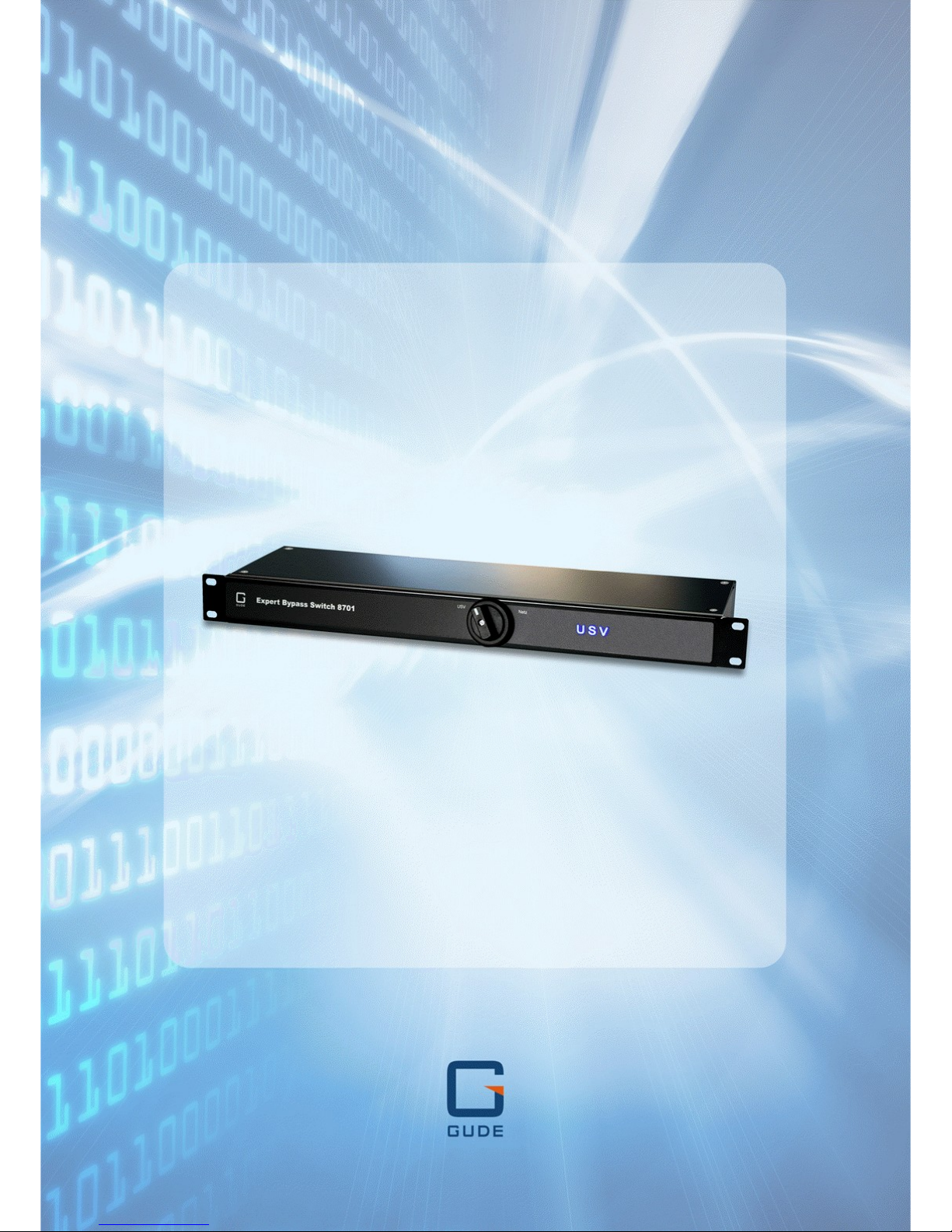
Expert Bypass Switch 87 01
© 2016 Gude Analog- und
Digitalsysteme GmbH
Manual Ver. 1.0.1
Manual
Page 2

Page 3

3
Expert Bypass Switch 8701 © 2016 Gude Analog- und Digitalsysteme GmbH
Table of contents
1. Device De scription 4
1.1 Secu r ity A d vice .............................................................................................................. 5
1.2 Conten t of Deliv er y ........................................................................................................ 5
1.3 Description ..................................................................................................................... 5
1.4 Installation ...................................................................................................................... 6
1.5 Techn ical Sp ec ifi c at i o n s ................................................................................................ 8
2. Operating 9
2.1 Opera t ing t h e d ev i c e ................................................................................................... 10
3. Support 11
3.1 Contact .......................................................................................................................... 12
3.2 Declarat i o n o f Con formity .......................................................................................... 13
0
Index
Page 4

Device Description
Page 5

5
Expert Bypass Switch 8701 © 2016 Gude Analog- und Digitalsysteme GmbH
Device Descript ion
1 Device De scription
1.1 Security Advice
· The device must be installed only by qualified personnel acc ording to the following installation and operating instructions.
· The manufacturer does not accept responsibility in c as e of improper use of the device
and particularly any use of equipment t hat may c aus e personal injury or material damage.
· The device contains no user-maintenable parts. All maintenance has to be performed
by factory trained service personnel.
· This device contains potentially hazardous voltages and should not be opened or disassembled.
· The device can be connected only to 230V AC (50 Hz or 60 Hz) power supply s oc k ets.
· The power cords, plugs and soc k et s have to be in good condition. Always connect the
device to properly grounded power sockets.
· The device is i ntended for indoor use only. Do NOT install t hem in an area where excessive moisture or heat is present.
· B ec ause of safety and approval is s ues it is not allowed to modify the device without
our permiss ion.
· P lease note the s afety advi s es and manuals of connect ed devic es , too.
· The device is NOT a toy. It has to be used or stored out or range of children.
· Care about packaging material. Plas t i cs has t o be s t ored out of range of children.
Please recycle the packaging materials.
· In case of further questi ons, about installation, operation or us age of the device, which
are not c lear after reading the manual, please do not hesitate to ask our support team.
· P lease, never leave connected equipment unattended, that can caus e damage.
· Connect only electrical devic es that do not have limit ed on-time. I.e. in c ase of failure,
all connected appliances have to cope with a continuous on-time without causing
damage.
1.2 Content of Delivery
The package includes:
· Expert Bypass Switch 8701
· CD-ROM with Manual
1.3 Description
The Expert Bypass Switch 8701 is a m ec hanical by pass switch for uninterrupted re-
placement of UPS systems
· Uninterrupted replacement or maintenance of UPS sys tems t hrough selection switch
without shutdown of connected loads
· S witch position „Netz“: Connected loads are operated with mains voltage directly
Page 6

6
Expert Bypass Switch 8701 © 2016 Gude Analog- und Digitalsysteme GmbH
Device Descript ion
· S witch position „USV“: Connected loads are operated with UPS syst em voltage
· Clearly visible LED display for switc h s t at us
· Low internal power consumption
· Developed and manufact ured in Germany
1.4 Installation
Connectors on the rear panel (EBS 8701-1)
Expert Bypass Switch 8701-1
1. Load input "von Netz" (I E C C14, max. 10 A)
2. Load output "zur USV " (I EC C13, max. 10 A)
3. Load input "von USV" (I E C C14, max. 10 A)
4. 6 x Load outputs "zur Last" to consumer (IEC C13, max . 10 A )
5. 10 A fuse for load output (1 x I EC C19, max. 16 A )
6. 1x Load output "zur Last" to consumer (IEC C19, max . 16 A)
Block diagram
Page 7

7
Expert Bypass Switch 8701 © 2016 Gude Analog- und Digitalsysteme GmbH
Device Descript ion
Connectors on the rear panel (EBS 8701-2)
1. Load input "von Netz" (I E C C20, max. 16 A)
2. Load output "zur USV " (I EC C19, max. 16 A)
3. Load input "von USV" (I E C C20, max. 16 A)
4. 6 x Load outputs "zur Last" to consumer (IEC C13, max . 10 A )
5. 1x Load output "zur Last" to consumer (IEC C19, max . 16 A)
Block diagram
Start-up the device
· Connect the load input "von Netz" to the mains supply.
· Connect the load output "zur USV" with t he input of the UPS.
· Connect the load input "von USV" with the output of the UPS.
· Connect the load outputs "zur Last" with the c onsumer.
Th e 16 A lead plug IEC C19 or IEC C20 are secured as regards their type against
unintentional loosening. They mus t be inserted up to the stop, otherwise there is no secure connection. The plug must not wobble in the sock et, or there is no tight c onnection.
Page 8

8
Expert Bypass Switch 8701 © 2016 Gude Analog- und Digitalsysteme GmbH
Device Descript ion
1.5 Technical Specifications
Interfaces
1 x Et hernet port (RJ45)
1 x Mains supply (IEC C14, max. 10 A)
4 x Load inputs (IEC C120, max. 16 A)
4 x Load outputs (IEC C19, max. 16 A)
2 x RJ45 for ext ernal sensor
Environment
· Operating temperature
· S t orage temperature
· Humidity
0°C - 50 °C
-20°C - 70 °C
0% - 95% (non-condensing)
Case
powder coated, galvanized st eel s heet
Measurements
19" (inches), 1 Rack Unit, (Depth 165
mm)
Weight
approx. 2. 2 k g
Page 9

Operating
Page 10

10
Expert Bypass Switch 8701 © 2016 Gude Analog- und Digitalsysteme GmbH
Operating
2 Operating
2.1 Operating the device
1. Switc h between "USV" and "LED"
2. LED indicator "USV" (UPS)
3. LED indicator "NETZ" (Mains)
Settings
In normal operat ion t he switch is set to " USV " and the terminals are powered by t he
connected UPS. If you want t o replace the UPS for maintenance purposes, turn the
switc h from "USV" to "Netz" . Caution: W hen turning the switch a greater force is necessary, this is normal. In the "Netz " setti ng the devic es are directly supplied from the
mains . See the block diagrams in chapter Installation .
6
Page 11

Support
Page 12

12
Expert Bypass Switch 8701 © 2016 Gude Analog- und Digitalsysteme GmbH
Support
3 Support
If you have further questions about installati on or operation of the unit, please c ontac t our
support team. Furthermore, we present in our support wiki at www.gude.info/wiki FAQs
and configuration examples.
3.1 Contact
Gude Analog- und Digitalsy steme GmbH
Eintrachts traße 113
50668 Cologne
Germany
Phone: +49-221-912 90 97
Fax: +49-221-912 90 98
E-Mail: mail@gude.info
Internet: www.gude.info
shop.gude.info
Managing Director: Dr.-Ing. Michael Gude
District Court: Köln, HRB-Nr. 17 7 84
WE E E -number: DE 58173350
Value added tax identification number (VAT): DE 122778228
Page 13

13
Expert Bypass Switch 8701 © 2016 Gude Analog- und Digitalsysteme GmbH
Support
3.2 Declaration of Conformity
EG Konformitätserklärung
EC Declara tion of Conformity
Der Hersteller
The manufacturer
Gude Analog- und Digitalsysteme GmbH
Eintrachtstr. 113
50668 Köln (Deutschland)
erklärt hiermit, dass die folgenden Produ kte / h ereby declares that the foll o wing p rod ucts
Produktbezeichnung
Product name
Ex pert Bypass Switch 8701-1
Ex pert Bypass Switch 8701-2
Beschreibung
Description
IP gesteuerte schaltbare Stromverteilung mit Energiemessung
IP remote controlled power distribution unit with energy metering
mit den B estimmungen d er nachstehenden EU-Richtl inien übereinstimmen / are in accordance with th e fol lowing European directives
2014/35/EU
Niederspannungsrichtlinie / Low Voltage Directive (LV D)
2014/30/EU
Elektromagnetische V erträglichkeit (EM V)
Electromagnetic Compatibility (EMC)
2011/65/EU
z ur Beschränkung der V erwendung bestimmter gefährlicher Stoffe
in Elektro- und Elektronikgeräten (RoHS) / on the restriction of the
use of certain hazardous substances in electrical and electronic
equipment (RoHS)
und d ass die nachstehenden harmonisierten Europäischen Normen zur An wendun g
gelangt sin d . / and comply with the foll o wing h armonised European standards.
EN 60950-1:2006/
A2:2013
Einrichtungen der Informationstechnik - Sicherheit
Information technology equipment - Safety
EN 55022:2010/
AC:2011
Einrichtungen der Informationstechnik - Funkstöreigenschaften
Information technology equipment - Radio disturbance characteristics
EN 55024:2010
Einrichtungen der Informationstechnik - Störfestigkeitseigenschaften / Information technology equipment - Immunity characteristics
EN 61000-3-2:2014
Elektromagnetische V erträglichkeit (EM V) Grenzwerte für Oberschwingungsströme / Electromagnetic Compatibility (EMC) Limits
for harmonic current emissions
EN 61000-3-3:2013
Elektromagnetische V erträglichkeit (EM V) Begrenzung von Spannungsänderungen, Spannungsschwankungen und Flicker
Electromagnetic Compatibility (EMC) Limitation of v oltage changes,
v oltage fluctuations and flicker
EN 50581:2012
Technische Dokumentation z ur Beurteilung von Elektro- und
Elektronikgeräten hinsichtlich der Beschränkung gefährlicher
Stoffe / T echnical documentation for the assessment of electrical
and electronic products with respect to the restriction of haz ardous
substances
Kö ln , 20.4.2016
Dr. Mi chael Gude, Geschäftsführer / G eneral manager, CEO
Page 14

14
Expert Bypass Switch 8701 © 2016 Gude Analog- und Digitalsysteme GmbH
Expert Bypass Switch 8701
© 2016 Gude Analog- und Digitalsysteme GmbH
6/24/2016
 Loading...