

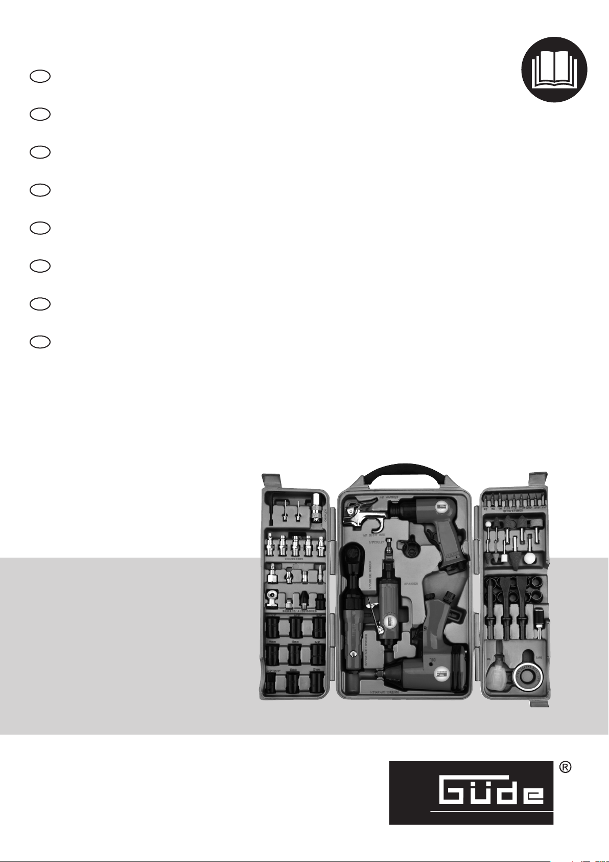
Gude 71 TLG. Translation Of The Original Instructions
---------
D
Originalbetriebsanleitung 2
DRUCKLUFTGERÄTE-SET
---------
---------
---------
---------
---------
---------
---------
GB
Translation of the original instructions 9
AIR TOOL KIT
F
Traduction du mode d’emploi d’origine 16
SET D‘OUTILS PNEUMATIQUES
CZ
Překlad originálního návodu k provozu 23
SADA PNEUMATICKÉHO NÁŘADÍ
SK
Preklad originálneho návodu na prevádzku 30
SÚPRAVA PNEUMATICKÉHO NÁRADIA
NL
Vertaling van de originele gebruiksaanwijzing 37
PERSLUCHTAPPARATEN SET
I
Traduzione del Manuale d’Uso originale 44
SET DI UTENSILI PNEUMATICI
SLO
Prevod originalnih navodil za uporabo 51
KOMPLET S PNEVMATSKIM ORODJEM
EG-KONFORMITÄTSERKLÄRUNG 58
EC-DECLARATION OF CONFORMITY •
DECLARATION CE DE CONFORMITÉ •
DICHARAZIONE DI CONFORMITÁ CE •
EG-CONFORMITEITVERKLARING •
PROHLÁŠENÍ O SHODĚ EU •
VYHLÁSENIE O ZHODE EÚ •
AZONOSSÁGI NYILATKOZAT EU •
IZJAVA O SUKLADNOSTI EU
71 TLG.
40401
DE
DE
Allgemein
Sehr geehrter Kunde,
Vielen Dank für das Vertrauen, dass Sie uns und unseren Produkten entgegenbringen. Mit dem Kauf dieses Güde-Produktes haben
Sie sich für ein qualitativ hochwertiges Gerät entschieden, das dem
aktuellen Sicherheitsstandard entspricht.
Bevor Sie jedoch ihr Gerät in Betrieb nehmen, lesen Sie bitte auf jeden Fall diese Bedienungsanleitung aufmerksam durch. Nehmen
Sie die Maschine erst in Betrieb, wenn Sie die Bedienungsanleitung vollständig gelesen und verstanden haben. Diese
Bedienungsanleitung enthält wichtige Hinweise, die zum sicheren und störungsfreien Betrieb ihrer Maschine unbedingt erforderlich
sind. Bewahren Sie diese daher immer bei der Maschine auf.
Betriebs- und Sicherheitshinweise
Druckluftwerkzeuge arbeiten mit unterschiedlich hohen Arbeitsdrücken. Der empfohlene Arbeitsdruck beträgt bei den
meisten Geräten 6 bar in Freilauf- oder Ruhephase.
Lesen Sie bitte diese Bedienungsanleitung sorgfältig durch, bevor Sie das Gerät in Betrieb nehmen.
A.V. 2 Nachdrucke, auch auszugsweise, bedürfen der Genehmigung. Technische Änderungen vorbehalten.
Abbildungen beispielhaft! Dies ist eine Orginal Bedienungsanleitung.
Sie haben technische Fragen? Eine Reklamation? Benötigen Ersatzteile oder eine Bedienungsanleitung?
Auf der Homepage der Firma Güde GmbH & Co. KG (www.guede.com) im Bereich Service helfen wir Ihnen schnell und unbürokratisch
weiter. Bitte helfen Sie uns Ihnen zu helfen. Um Ihr Gerät im Reklamationsfall identifizieren zu können benötigen wir die Seriennummer sowie
Artikelnummer und Baujahr. Alle diese Daten finden Sie auf dem Typenschild. Um diese Daten stets zur Hand zu haben, tragen Sie diese
bitte unten ein.
Seriennummer: Artikelnummer: Baujahr:
E-Mail: support@ts.guede.com
Ein größerer Druck würde aufgrund höherer Belastung die Lebensdauer Ihres Gerätes verkürzen.
Wasser in der Druckluftzufuhr kann Schäden am Gerät verursachen. Entwässern Sie Ihren Kompressor oder Ihr
Leitungssystem regelmässig! Reinigen Sie den Luftfilter ihrer Anlage mindestens einmal wöchentlich.
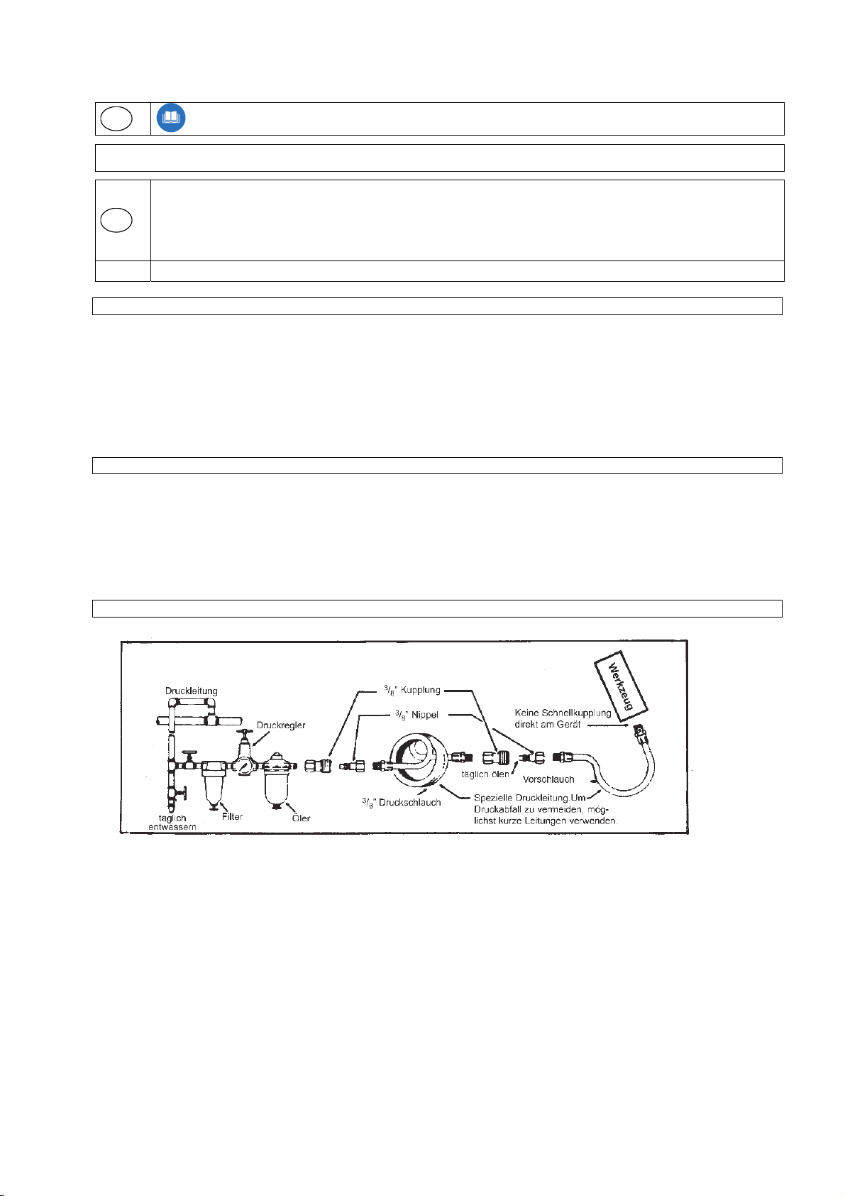
Inbetriebnahme und Wartung von Güde-Druckluftwerkzeugen
⅜”
Bevor Sie Ihr Druckluftwerkzeug in Betrieb nehmen, achten Sie auf folgende Punkte:
1. Dichten Sie den mitgelieferten Stecknippel mit Teflonband ab und schrauben Sie Ihn dann in den Druckluftanschluss.
2. Druckluftgerät nur mit ÖIer betreiben.
3. Druckminderer muss am Kompressor vorhanden sein (alle Güde Kompressoren sind mit Druckminderer ausgestattet).
4. Montieren Sie vor dem ÖIer einen Wasserabscheider (Filter).
5. Der maximale Betriebsdruck Ihres Druckluftwerkzeuges ist 6 bar. Sollten Sie Ihren Druckminderer höher als 6 bar
einstellen, kann Ihr Druckluftwerkzeug überlastet werden.
6. Bei längeren Betriebspausen empfehlen wir, das Druckluftwerkzeug gründlich zu reinigen und zu ölen. Bei
Wiederinbetriebnahme etwas Druckluftöl in den Anschluss des Druckluftgerätes geben, das Gerät kurz laufen lassen, dann
mit Druckluftöler betreiben. Einige Geräte sind mit einer stufenlosen Regulierung für Drehzahl und Schlagkraft ausgestattet.
(z. B. Schlagschrauber, Bohrmaschine links/rechts-Lauf, Meißelhammerset, Excenterschleifer, Rutscher etc.) Diese
Regulierungsschraube befindet sich direkt neben dem Luftanschluß des Gerätes.
7. Wir empfehlen beim Güde Druckluft-Schlagschrauber nur gehärtete Güde Stecknüsse zubenutzen. Sie sind in jedem guten
Fachhandel erhältlich. Dies gilt auch für Meißel in
versch. Größen für den Güde-Druckluftmeißelhammer.
Wir wünschen Ihnen viel Spaß mit Ihrem neuen Gerät und bitten Sie, unsere Gewährleistungbestimmungen zu
beachten.
2
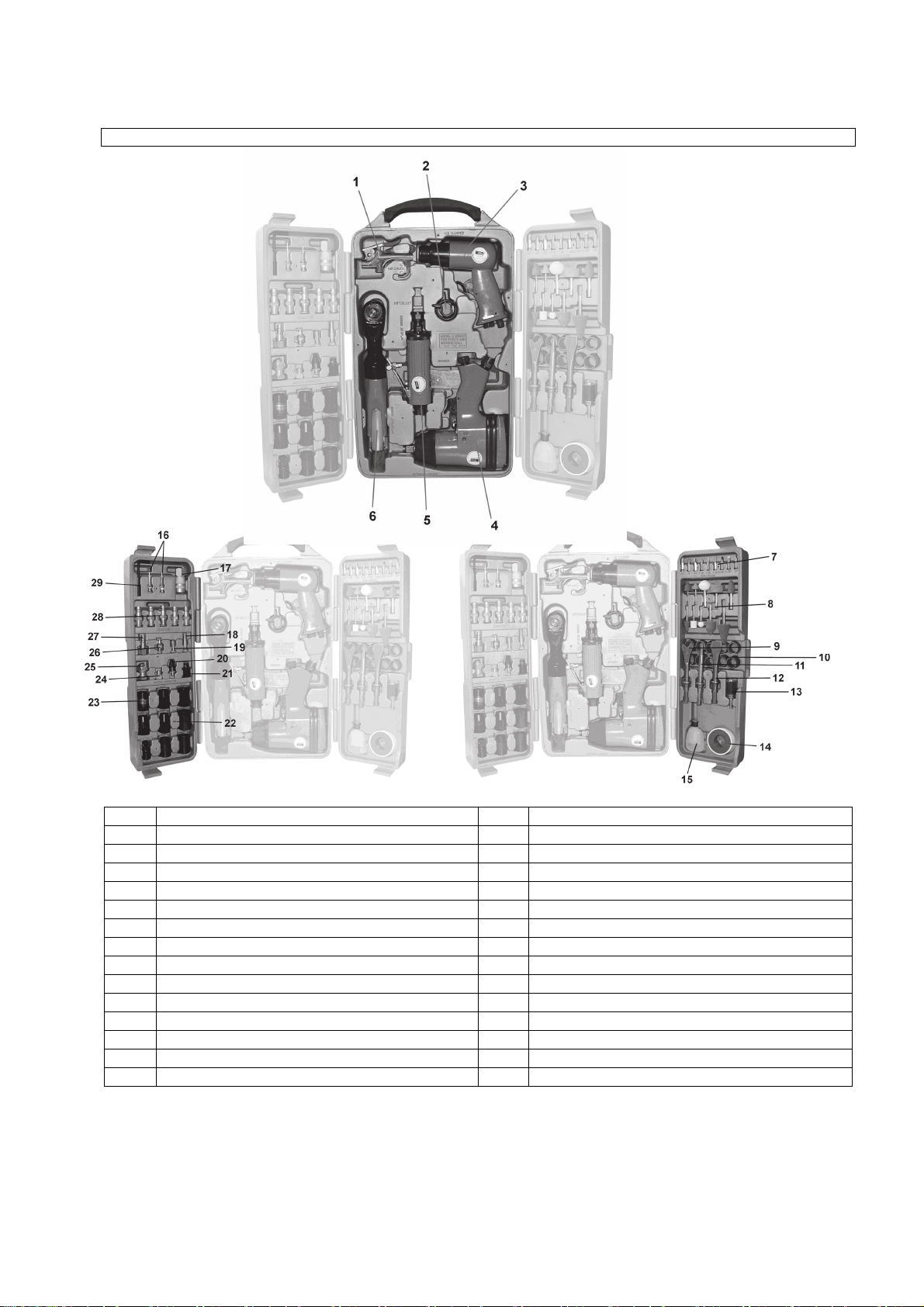
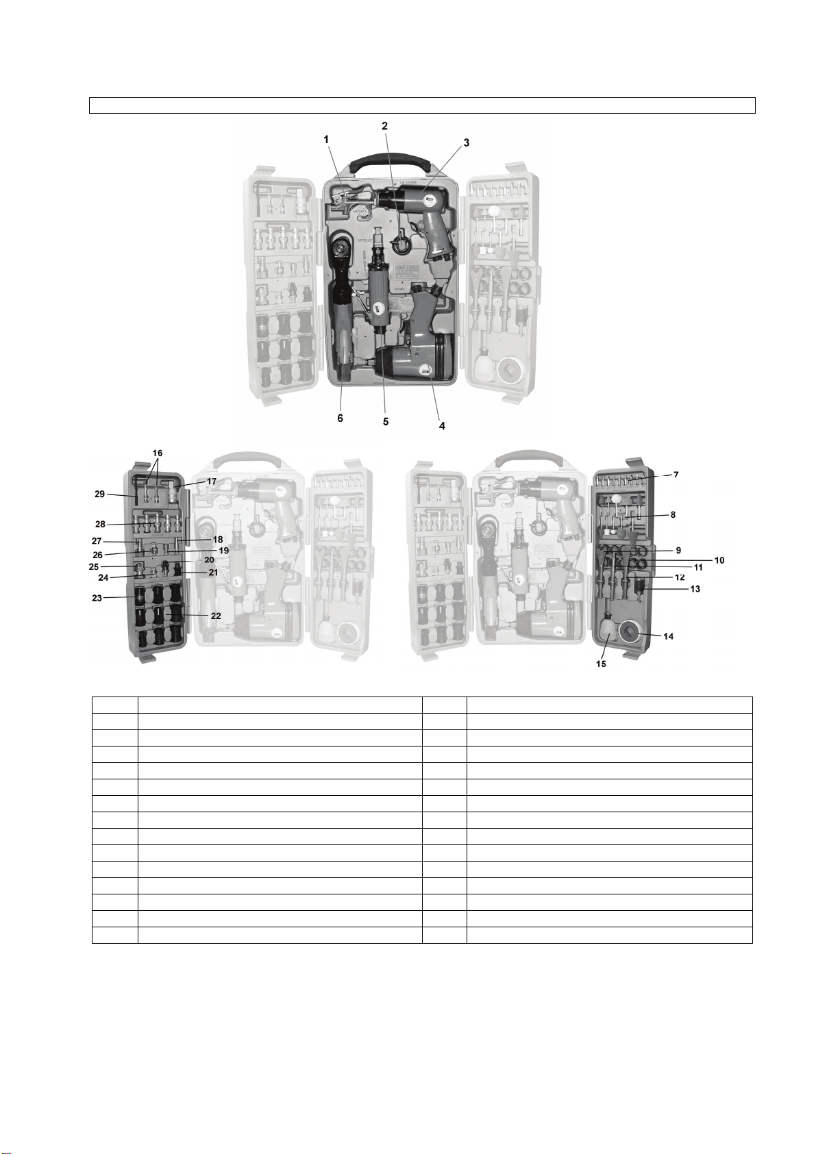
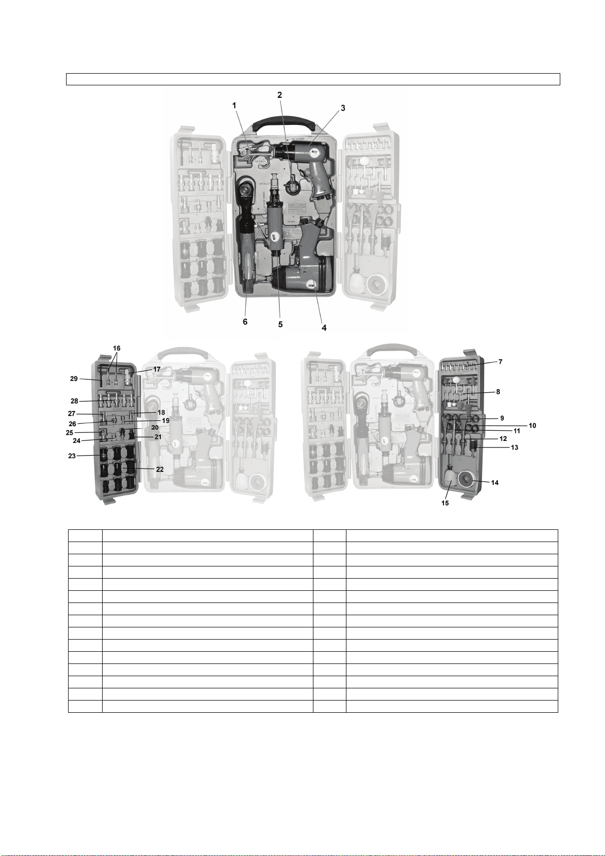
Geräte-Set
1 Druckluft-Pistole “Mini” 16 Ballfüllnadel
2 Meißelhaltefeder 17 Schlauchkupplung 3/8‘’ IG
3 Meißelhammer 18 Ausblasdüse
4 Schlagschrauber 19 Luftkammernfülladapter
5 Stabschleifer 20 Nadeladapter
6 Ratschenschrauber 21 Bitadapter
7 Bitsortiment 22 Gängiges Nusssortiment
8 Schleifstifte (3 mm und 6 mm) 23 Adapter 3/8’’/1/2’’
9 Trennmeißel 24 Schleifstiftspannzange
10 Schleifrollen 25 Ventilsteckeraufsatz
11 Spitzmeißel 26 Luftkammernfülladapter
12 Flachmeißel 27 Stecknippel 1/8’’ IG
13 Schleifrollenaufnahme 28 Stecknippelsortiment
14 Teflonband 29 Sechskantsteckschlüssel
15 Ölflasche
3

Gewährleistung
4
Die Gewährleistungszeit beträgt 12 Monate bei
gewerblicher Nutzung, 24 Monate für Verbraucher und
beginnt mit dem Zeitpunkt des Kaufs des Gerätes.
Die Gewährleistung erstreckt sich ausschließlich auf
Mängel, die auf Material- oder Herstellungsfehler
zurückzuführen sind. Bei Geltendmachung eines Mangels
im Sinne der Gewährleistung ist der Kaufbeleg, der das
Verkaufsdatum auszuweisen hat beizufügen.
Von der Gewährleistung ausgeschlossen sind
unsachgemäße Nutzung, wie z. B. Überlastung des
Gerätes, Gewaltanwendung, Beschädigungen durch
Fremdeinwirkung, Fremdkörper, sowie Nichtbeachtung
der Gebrauchs- und Aufbauanleitung und normaler
Verschleiß.
Der Schlagschrauber
5
Technische Daten
Leistung ~0,34 kw
Max. Lösedrehmoment 310 Nm
Max. Anziehdrehmoment 250 Nm
Drehzahl 7000 U/min.
Arbeitsbereich (max. Gewindegröße) M 16
Max. Zulässiger Arbeitsdruck 6 bar
Schalldruckpegel 89 db (A)
Vibration (unter Last) < 2,5 m/sec²
Vierkantaufnahme ½ Zoll
Luftverbrauch ca. 6 l/sec.
Empfohlener Schlauch-ø, innen 9mm
Gewicht 2,3 kg
Luftverbrauch bei max. Drehmoment ca. 350 l/min.
Benötigte Luftqualität, Luftversorgung:
Gereinigt u. ölvernebelt. Über eine Wartungseinheit mit Filterdruckminderer und Nebelöler.
Einstellwerte für das Arbeiten:
Eingestellter Arbeitsdruck (Fließdruck) am Druckminderer 6 bar.
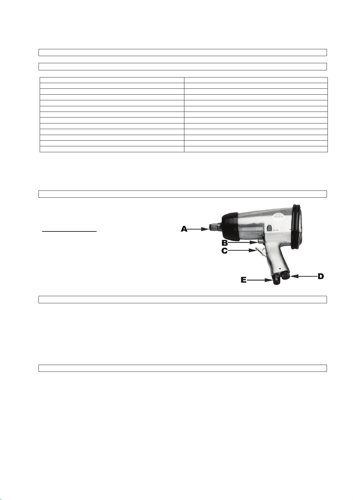
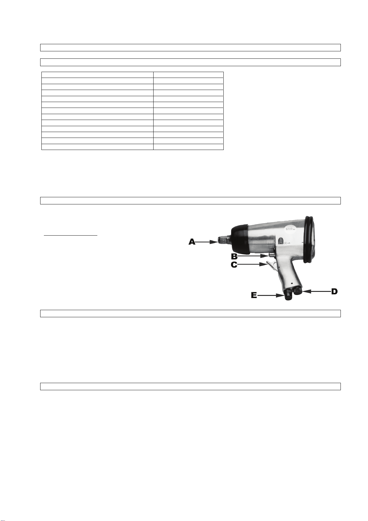
Abbidung
Pos. Bezeichnung
A Vierkant für Nussaufnahme
B Umlenkhebel Rechts- und Linkslauf
C Abzughebel
D Luftregler bzw. Drehmomentregler
E Druckluftanschluß
Bestimmungsgemäße Verwendung
Der Schlagschrauber ist ein handliches, druckluftbetriebenes Gerät für den handwerklichen Einsatz. Er eignet sich zum Befestigen
und Lösen von Verschraubungen im Kfz-Bereich (Reifenmontage, festsitzende Fahrgestellschrauben) oder an Montagebändern
sowie im landwirtschaftlichen Bereich.
Die Abluft tritt über dem Abzug seitlich aus. Die Steckaufsätze können einfach schnell gewechselt werden. Der Druckluftanschluss
erfolgt über eine Schnellkupplung. Beachten Sie beim Anziehen von Schrauben und Muttern die notwendigen Anzugsdrehmomente.
Verwenden Sie nach dem Anziehen einen Drehmomentschlüssel.
Beachten Sie:
Tragen Sie beim Arbeiten mit dem Schlagschrauber die erforderliche Schutzkleidung.
Beachten Sie die Sicherheitsbestimmungen.
Sicherheitsbestimmungen
Schützen Sie sich und Ihre Umwelt durch geeignete Vorsichtsmaßnahmen vor Unfallgefahren.
- Schlagschrauber nicht zweckentfremden
- Druckluftwerkzeuge vor Kindern sichern!
- Nur ausgeruht und konzentriert zu Werke gehen
- Druckluftanschluss nur über eine Schnellverschlusskupplung
- Arbeitsdruckeinstellung muss über einen Druckminderer erfolgen
- Als Energiequelle keinen Sauerstoff oder brennbare Gase verwenden
- Vor Störungsbeseitigung Gerät von der Druckluftquelle trennen.
- Nur Originalersatzteile verwenden
- Nie bei voller Leerlaufdrehzahl unbelastet laufen lassen.
- Tragen Sie beim Arbeiten mit dem Schlagschrauber die erforderliche Schutzkleidung
(Antriebswelle)

Inbetriebnahme
6
Schrauben Sie den mitgelieferten Stecknippel in den Druckluftanschluss (Pos. E) und dichten Sie diesen mit Teflonband ab ! Stecken
Sie den benötigten Steckaufsatz auf den Vierkant (Pos. A). Stellen Sie die richtige Drehrichtung am Umlenk-hebel (Pos. B) ein:
Stecken Sie den Steckaufsatz auf den Schraubknopf. Betätigen Sie den Abzug (Pos. C). Am Luftregler (Pos. D) kann durch drehen
die Luftzufuhr stufenlos reguliert werden:
Der Anschluß an die Druckluftquelle erfolgt über einen flexiblen Druckluftschlauch mit Schnellkupplung.
Wartung und Pflege
Die Einhaltung der hier angegebenen Wartungshinweise sichert für dieses Qualitätsprodukt eine lange Lebensdauer und einen
störungsfreien Betrieb. Für eine dauerhafte, einwandfreie Funktion Ihres Schlagschraubers ist eine regelmäßige Schmierung
Voraussetzung. Folgende Möglichkeiten stehen Ihnen in Sachen Schmierung zur Auswahl:
a) Über einen Nebelöler
Eine komplette Wartungseinheit beinhaltet einen Nebelöler und ist am Kompressor angebracht.
b) Über einen Leitungsöler
In unmittelbarer Nähe des Werkzeugs (ca. 50 cm Abstand) wird ein Leitungsöler installiert, der das Werkzeug ausreichend mit Öl
versorgt. War das Druckluftwerkzeug mehrere Tage außer Betrieb, müssen Sie vor dem Einschalten 5-10 Tropfen SpezialWerkzeugöl in den Druckluftanschluss geben.
c) Von Hand
Ist bei Ihrer Anlage weder eine Wartungseinheit, noch ein Leitungsöler vorhanden, so müssen Sie vor jeder Inbetriebnahme Ihres
Schlagschraubers 3 - 5 Tropfen Spezial-Werkzeugöl in den Druckluftanschluss geben. Lagern Sie Ihr Druckluftwerkzeug nur in
trockenen Räumen.
Drücken nach hinten (reverse) Linkslauf = Schraube lösen
Drücken nach vorn (forward) Rechtslauf = Schraube anziehen
Markierung 9 = max. Drehmoment (4)
Markierung 0 = min. Drehmoment (1)
Der Meißelhammer
Richten Sie das rotierende Ende des Werkzeuges niemals gegen sich selbst oder gegen andere Personen. Das Gerät mit dem
Luftzufuhrschlauch verbinden.
Technische Daten
Anschlussgewinde ¼ ”
Betriebsdruck 6 bar
Luftverbrauch 350 l/min.
Schlagzahl 3000/min.
Wartung und Pflege
Die Wartung darf nur von unterwiesenen Personen durchgeführt werden.
Die Einhaltung der hier angegebenen Wartungshinweise sichert für dieses Qualitätsprodukt eine lange Lebensdauer und einen
störungsfreien Betrieb. Trennen Sie das Gerät bei Wartungs- und Pflegearbeiten von der Druckluftquelle. Für eine dauerhaft
einwandfreie Funktion Ihres Druckluftwerkzeuges ist eine tägliche Reinigung und eine regelmäßige Schmierung unerläßlich.
Verwenden Sie hierfür nur spezielles Druckluftöl.
Folgende Möglichkeiten stehen Ihnen in Sachen Schmierung zur Auswahl:
a) über einen Nebelöler
Eine komplette Wartungseinheit beinhaltet einen Nebelöler und ist am Kompressor angebracht.
b) über einen Leitungsöler
In unmittelbarer Nähe des Werkzeuges (ca. 50 cm Abstand ) wird ein Leitungsöler installiert,
der das Werkzeug ausreichend mit Öl versorgt.
c) von Hand
Ist bei Ihrer Anlage weder eine Wartungseinheit noch ein Leitungsöler vorhanden, so müssen vor jeder Inbetriebnahme des
Druckluft- Werkzeuges 3-5 Tropfen Öl in den Druckluftanschluss gegeben werden. War das Druckluft- Werkzeug mehrere Tage
außer Betrieb, müssen Sie vor dem Einschalten 5-10 Tropfen Öl in den Druckluftanschluss geben. Lagern Sie Ihre
Druckluftwerkzeuge/ -geräte nur in trockenen Räumen.
Achtung:
Gelegentlich Feder (Explosionszeichnung – Pos. 1) wechseln
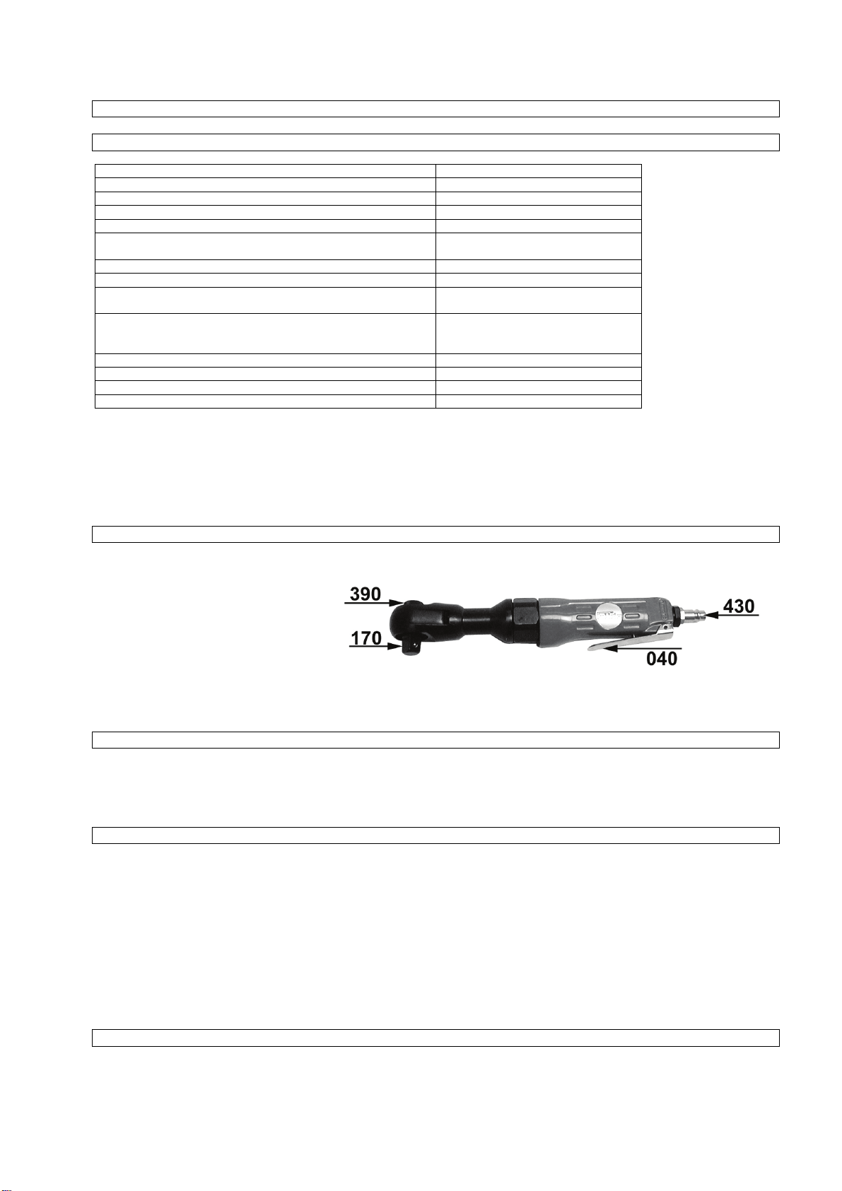
Der Ratschenschrauber
7
Technische Daten
Leerlaufdrehzahl 160 U/min
Leistung 0,272 kW
max. Lösedrehmoment 40 Nm
Arbeitsbereich (max. Gewindegröße) M 8
max. zulässiger Arbeitsdruck 6 bar
Geräuschemissionen nach DIN 45635 Teil 20 / 09.90
Schalleistungplegel L
Arbeitsplatzbezogener Emissionswert L
Maximaler Messflächen-Impulsschalldruckplegel L
Vibration (unter Last) nach DIN EN 28662 Teil 1 / 01.93
bzw. E DIN ISO 8662 Teil 1 / 01.93
Vierkantaufnahme ½ Zoll
Luftverbrauch ca. 310 l/min
Empfohlener Schlauchdurchmesser innen 6 mm
Gewicht 1,24 kg
Benötigte Luftqualität: Gereinigt und ölvernebelt
Leistungsgröße des Kompressors: Fülleistung des Kompressors min. 180 l/min.
Einstellwerte für das Arbeiten: Eingestellter Arbeitsdruck am Druckminderer oder
Abbildung
WAI max. c
PAI max.
PAI max, 1m
Dies entspricht einer Motorleistung von 1,5 kW.
Filterdruckminderer 6 bar.
103 dB (A)
93 dB (A)
90 dB (A)
14,7 m/sec2
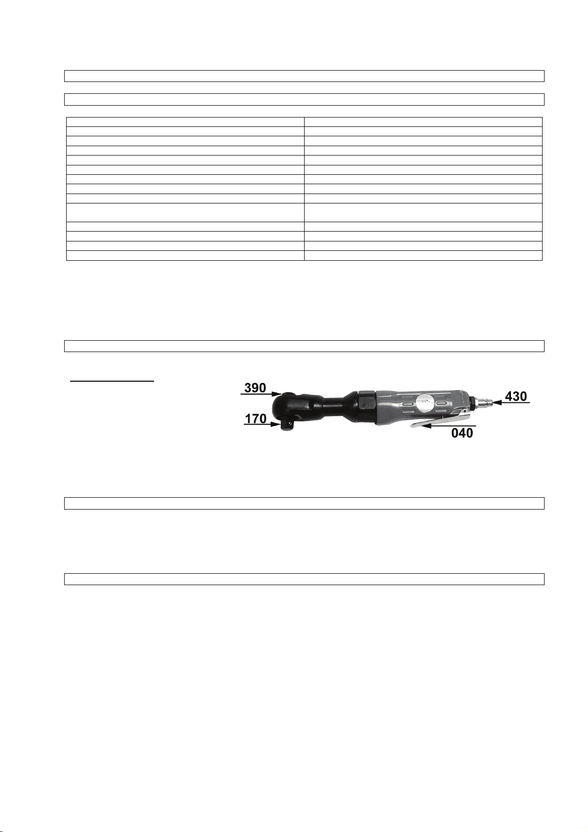
Pos. Bezeichnung
040 Abzughebel
170 Antieb
390 Umschalthebel für
430 Stecknippel für Druckluftanschluss
Bestimmungsgemäße Verwendung
Der Ratschenschrauber ist ein handliches, druckluftbetriebenes Werkzeug für den handwerklichen Einsatz. Er ist für das Arbeiten an
Kraftfahrzeugen, Motorrädern, landwirtschaftlichen Geräten oder Montagebändern, besonders an schwer zugänglichen Stellen, sehr
gut geeignet. Nach Erreichen des maximalen Drehmoment ist ein weiteres Anziehen von Hand, mit dem Ratschenschrauber nicht
zulässig. Die Abluft tritt vorne am Gehäuse wieder aus. Der Druckluftanschluss erfolgt über eine Schnellkupplung.
Sicherheitsbestimmungen
Schützen Sie sich und Ihre Umwelt durch geeigneten Vorsichtsmaßnahmen vor Unfallgefahren.
Rechts-/ Linkslauf
- Rotierende Teile nicht berühren.
- Ratschenschrauber nicht zweckentfremden.
- Druckluftwerkzeuge vor Kinder sichern.
- Nur ausgeruht und konzentriet zu Werke gehen.
- Druckluftanschluss nur über eine Schnellverschlusskupplung.
- Arbeitsdruckeinstellung muss über einen Druckminderer erfolgen.
- Als Energiequelle keinen Sauerstoff oder brennbare Gase verwenden.
- Vor Störungsbeseitigung Gerät von der Druckluftquelle trennen.
- Nur Originalersatzteile verwenden.
- Nie bei voller Leerlaufdrehzahl unbelastet laufen lassen.
- Tragen Sie beim Arbeiten mit dem Ratschenschrauber die erforderliche Schutzkleidung, insbesondere
einen Gehörschutz.

Inbetriebnahme
8
Schrauben Sie den mitgelieferten Stecknippel (Pos. 430) in den Reduziernippel. Benutzen Sie hierfür einen Ring- oder
Gabelschlüssel. Achtung: Gewinde mit Teflonband abdichten!
Auf den Antrieb (Pos. 170) den gewünschten Steckschlüsseleinsatz aufstecken. Luftschlauch mit Schnellkupplung am Stecknippel
anschließen. Steckschlüsseleinsatz auf die zu lösende bzw. anzuziehende Mutter oder Schraube aufsetzen. Gewünschte
Drehrichtung am Umschalthebel (Pos. 390) einstellen, Abzughebel (Pos. 040) betätigen.
Wartung und Pflege
Die Einhaltung der hier angegebenen Wartungshinweise sichert für dieses Qualitätsprodukt eine lange Lebensdauer und einen
störungsfreien Betrieb.
Für eine dauerhafte und einwandfreie Funktion Ihres Ratschenschraubers ist eine regelmäßige Schmierung Voraussetzung.
Verwenden Sie hierfür nur spezielles Werkzeugöl.
Folgende Möglichkeiten stehen Ihnen in Sachen Schmierung zur Auswahl:
a) über einen Nebelöler
Eine komplette Wartungseinheit beinhaltet einen Nebelöler und ist am Kompressor angebracht.
b) über einen Leitungsöler
In unmittelbarer Nähe des Werkzeuges (ca. 50 cm Abstand) wird ein Leitungsöler installiert, der das Werkzeug ausreichend mit Öl
versorgt.
c) von Hand
Ist bei Ihrer Anlage weder eine Wartungseinheit noch ein Leitungsöler vorhanden, so müssen vor jeder Inbetriebnahme des DruckluftWerkzeuges 3-5 Tropfen Öl in den Druckluftanschluss geben.
Bewahren Sie das Druckluft-Werkzeug nur in trockenen Räumen auf.
Der Geradschleifer
Richten Sie das rotierende Ende des Werkzeuges niemals gegen sich selbst oder gegen andere
Personen. Das Gerät mit dem Luftzufuhrschlauch verbinden.
Techniche Daten
Anschlussgewinde ¼”
Betriebsdruck 6 bar
Luftverbrauch ca. 350 l/min.
Drehzahl 22000 U/min.
Wartung und Pflege
Die Wartung darf nur von unterwiesenen Personen durchgeführt werden.
Die Einhaltung der hier angegebenen Wartungshinweise sichert für dieses Qualitätsprodukt eine lange Lebensdauer und einen
störungsfreien Betrieb. Trennen Sie das Gerät bei Wartungs- und Pflegearbeiten von der Druckluftquelle. Für eine dauerhaft
einwandfreie Funktion Ihres Druckluftgerätes ist eine tägliche Reinigung und eine regelmäßige Schmierung unerläßlich. Verwenden
Sie hierfür nur spezielles Druckluftöl.
Folgende Möglichkeiten stehen Ihnen in Sachen Schmierung zur Auswahl:
a. über einen Nebelöler
Eine komplette Wartungseinheit beinhaltet einen Nebelöler und ist am Kompressor angebracht.
b. über einen Leitungsöler
In unmittelbarer Nähe des Werkzeuges (ca. 50 cm Abstand ) wird ein Leitungsöler installiert,
der das Werkzeug ausreichend mit Öl versorgt.
c. von Hand
Ist bei Ihrer Anlage weder eine Wartungseinheit noch ein Leitungsöler vorhanden, so müssen vor jeder Inbetriebnahme des
Druckluft- Werkzeuges 3-5 Tropfen Öl in den Druckluftanschluss gegeben werden. War das Druckluft- Werkzeug mehrere Tage
außer Betrieb, müssen Sie vor dem Einschalten 5-10 Tropfen Öl in den Druckluftanschluss geben. Lagern Sie Ihre
Druckluftwerkzeuge/ -geräte nur in trockenen Räumen.
GB
Please read carefully the following Operating Instructions before putting the appliance into operation
A.V. 2 Any reprints, even partial, are subject to approval. Technical changes reserved.
Illustrative pictures! Translation of original operating instructions.
GB
Do you have any technical questions? Any claim? Do you need any spare parts or operating instructions?
We will quickly help you and without needles bureaucracy at our web pages at www.guede.com in the Servicing part. Please help us be able
to help you. In order to identify your device in case of claim we need the serial No., product No. and year of production. Al l this data can be
found on the type label. Please enter it here for future reference:
Serial No.: Order No.: Year of production:
E-Mail: support@ts.guede.com
3/8“
General
Dear Customer
Thank you for your confidence in our products and us. By buying a Güde product you have decided to buy a quality product that
corresponds with the present safety standards.
Please read carefully the operational manual before you start using your tool. Once you have read and understood the manual, only
then start using your tool. The manual includes important instructions that are necessary for safe and trouble free operation of your
tool. Please store it near to the tool.
Operational and safety instructions
Pneumatic tools work with working pressure of different values. The recommended work pressure amounts to 6 bars
for most machines when idle or when at standstill.
Higher pressure would result in shortening the service life of your machine due to heavy load.
Water in the compressed air inlet can damage the machine. Therefore it is necessary to remove the water from the
compressor or piping on regular basis! The air filter should be cleaned at least once a week.
Güde pneumatic tools start up and maintenance
The following points must be observed before starting to use the pneumatic tools.
1. Pneumatic tools should be operated only with the lubricating device on.
2. A pressure reducing valve must be on the compressor (all Güde compressors are equipped with a reducing valve).
3. Fit a water separator (filter) before the lubricating device.
4. Maximal operating pressure of the pneumatic tool is 6 bars. If you set the reducing valve at value higher than 6 bars, the
pneumatic tool can get overloaded.
5. If there are longer breaks in operation, we would recommend you should thoroughly clean and lubricate the pneumatic
tools with oil. When starting to run it again add a bit of oil into the pneumatic tool connector, and then use it with the
pneumatic lubrication equipment on. Some machines are equipped with a smooth regulation of revolutions and impact
power (etc. an impact fastener, a drill with left or right hand rotation, a set of chipping hammers, an eccentric grinder, a
hand vibration grinder etc.). This control screw is located directly next to the tool air connector.
6. For the Güde pneumatic impact fastener we would recommend to use only hardened detachable Güde nuts. You should be
able to purchase them in any good specialized shop. This is valid for chipping hammers of various sizes and Güde
pneumatic chipping hammer.
We hope you will enjoy working with your new tools. Please notice our guarantee provisions.
9
Tool set
10
1 “Mini” pneumatic pistol 16 Ball inflating needle
2 Chisel guard spring 17 Hose coupling 3/8‘’ IG
3 Chisel stabber 18 Exhaust nozzle
4 Impact tightener 19 Air chamber refill adapter
5 Rod grinder 20 Needle adapter
6 Ratchet tightener 21 Bit adapter
7 Range of bits 22 Nuts regular range
8 Grinding pins (3 mm and 6 mm) 23 Adapter 3/8’’/1/2’’
9 Cutting knife 24 Grinding pin tie
10 Grinding rollers 25 Valve extension
11 Pointed chisel 26 Air chamber refill adapter
12 Cold chisel 27 Insert coupling 1/8’’ IG
13 Grinding rollers clamp 28 Range of insert couplings
14 Teplon tape 29 Hexagon socket spanner
15 Bottle of oil

Guarantee
11
A warranty period of 12 months applies to commercial
use and 24 months apply to private use and commences
on the day of purchase of the device.
Warranty applies exclusively to failures due to defective
material or workmanship. An original sale slip with
indication of date of sale must be presented in case of
claiming for the warranty rights.
Warranty does not cover unprofessional use such as
device overload, violent use, damage caused by third
party or foreign materials, failure to comply with
operations and assembly manual, and normal wear and
tear.
Impact fastener
12
Technical data
Capacity ~0,34 kw
Max. torque for loosening 310 Nm
Max. torque for fastening 250 Nm
Revolutions 7000 rpm
Working capacity (max. thread size) M 16
Max. admissible working pressure 6 bar
Acoustic pressure level 89 db (A)
Vibration (loaded) < 2,5 m/sec²
Square clamp ½ inch
Air consumption ca 6 l/sec.
Recommended hose cross section, inner 9 mm
Weight 2,3 kg
Air consumption at max. fastening torque ca 350 l/min.
Air quality needed, air supply:
Clear air with oil mist. Use a maintenance unit with a filter reducing valve and an oil atomizer. .
Adjusting working values:
Working pressure set on the pressure reducing valve is 6 bars.
Illustration
Item Description
A Square for nut fastening
B Lever for switching over from left to right
C Release lever
D Air regulator or tightening torque regulator
E Pneumatic connector
Using the tool for its purpose
The impact fastener is an easy-to-use pneumatic tool for craftsmen. It is suitable for fastening and loosening of screwed connections
in cars (tyre fitting, dead chassis screws), for assembly belts or in agriculture.
Air escapes through the side outlet. Fitting a replacement is very easy and quick. Pneumatic connector is equipped with a quick
coupling device. When fastening screws and nuts you should observe the necessary tightening torques. For tightening use the torque
key.
Please observe the following directions:
When working with the impact fastener wear appropriate protective clothing.
Observe safety regulations.
Safety provisions
Protect yourself and your surroundings by preventing any accident risks.
- Impact fastener should not be used for any other purpose than it has been designed for.
- Pneumatic tools should be kept away from children.
- Work only once you are fully concentrating and feel rested.
- Use a coupling with a quick closing device for pneumatic connection.
- Working pressure should be set using the control valve.
- Do not use oxygen or gaseous fuel as energy supplies.
- Disconnect the machine from the compressed air supply before starting to repair a possible defect.
- Use only original spare parts.
- Don’t let the machine run unloaded at full idle speed.
- Wear necessary protective clothing when working with impact fastener.
(drive shaft)

Start up
13
Screw the nipple, part of the delivery, into the pneumatic connection (item E) and fasten it with a Teflon tape. The fitting needed is slid
into the square (item A). Set the right direction of revolution (item B) on the switching lever:
Pressing backwards (reverse) left hand operation = screw loosening
Pressing forwards (forward) right hand operation = screw tightening
Install the fitting into the screw knob. Press the trigger (item C). It is possible to control the air supply with the air control (item D).
A flexible pneumatic hose with a quick coupling device is used for the connection to the compressed air supply.
Maintenance
If you observe the following maintenance directions you will ensure a long service life of this quality product and a trouble free
operation. During the maintenance always disconnect the compressed air supply. To ensure trouble free performance of your
pneumatic tool, it is necessary to carry out everyday cleaning and regular lubrication. Use only special pneumatic oil.
a) Using oil atomiser
Comprehensive maintenance unit which consists of an oil atomiser and it is located in the compressor.
b) Using an oiling can installed into the piping
Install a lubricating device into the piping in an immediate vicinity of the tools (distance of about 50 cm), the lubricating device supplies
the tools with a sufficient amount of oil. If the pneumatic machine is out of work for several days, you must use 5-10 drops of special
tool oil for the pneumatic connecter
c) Hand lubrication
If you do not have the maintenance unit or the lubricating device installed into the piping at your disposal, you must use 3-5 drops of
special tool oil for the pneumatic connecter before each start-up of the impact fastener. Pneumatic tools should be stored in dry
rooms.
Chipping hammer
Never aim at yourself or other persons with the rotating machine end. Connect the machine to the air supply hose.
Mark 9 = max. tightening torque (4)
Mark 0 = min. tightening torque (1)
Technical data
Connecting thread ¼ ”
Operational pressure 6 bar
Air consumption 350 l/min.
Impact number 3000/min.
Maintenance
Maintenance can be done only by people with necessary qualifications.
If you observe the following maintenance directions you will ensure a long service life of this quality product and a trouble free
operation. During the maintenance always disconnect the compressed air supply. To ensure trouble free performance of your
pneumatic tool, it is necessary to carry out everyday cleaning and regular lubrication. Use only special pneumatic oil.
In terms of lubrication you have the following options:
a) Using oil atomiser
Comprehensive maintenance unit which consists of an oil atomiser and it is located in the compressor.
b) Using an oiling can installed into the piping
Install a lubricating device into the piping in an immediate vicinity of the tools (distance of about 50 cm), the lubricating device supplies
the tools with a sufficient amount of oil. If the pneumatic machine is out of work for several days, you must use 5-10 drops of special
tool oil for the pneumatic connecter
c) Hand lubrication
If you do not have the maintenance unit or the lubricating device installed into the piping at your disposal, you must use 3-5 drops of
special tool oil for the pneumatic connecter before each start-up of the impact fastener. Pneumatic tools should be stored in dry
rooms.
Attention:
Replace the spring occasionally (drawing of a dismantled tool – item 1)
Screwdriver with ratchet
14
Technical data
Idle speed 160 rev./min
Capacity 0,272 kW
Max. loosening torque 40 Nm
Working capacity (max. thread size) M 8
Max. admissible work pressure 6 bar
Noise emission
under DIN 45635 part 20 / 09.90
Acoustic performance level L
Emission level for workplace L
WAI max. c
PAI max.
Maximal level of measuring area impulse acoustic pressure L
max, 1m
Vibrations (loaded)
PAI
103 dB (A)
93 dB (A)
90 dB (A)
14,7 m/sec
2
under DIN EN 28662 part 1 / 01.93
or E DIN ISO 8662 part 1 / 01.93
Square clamp ½ inch
Air consumption ca 310 l/min
Recommended inner hose cross section 6 mm
Weight 1,24 kg
Air quality needed: Clean with oil mist:
Compressor capacity: Compressor charging capacity: 180 l/min.
Corresponds to 1,5 kW.
Adjusting values for work: Working pressure setting on the pressure reducing
valve or filter reducing valve 6 bars.
Illustration
Item Description
040 Release lever
170 Drive
390 Switching lever for right/left
operation
430 Pneumatic nipple connector
Using the tool for its purpose
The screwdriver with ratchet is an easy-to-use pneumatic tool for craftsmen. It is very suitable for work on cars, motorcycles,
agricultural equipment or assembly belts, in particular at hard to access places. To reach the maximal tightening torque it is not
admissible to use any further manual tightening using the screwdriver. Air escapes through the front part of the machines. The
pneumatic connecter is equipped with a quick coupling device.
Safety provisions
Protect yourself and your surroundings by preventing any accident risks.
- Screwdriver with ratchet should not be used for any other purpose than it has been designed for.
- Don’t touch rotating parts.
- Pneumatic tools should be kept away from children.
- Work only once you are fully concentrating and feel rested.
- Use a coupling with a quick closing device for pneumatic connection.
- Working pressure should be set using the control valve.
- Do not use oxygen or gaseous fuel as energy supplies.
- Disconnect the machine from the compressed air supply before starting to repair a possible defect.
- Use only original spare parts.
- Don’t let the machine unloaded at full idle speed.
- Wear necessary protective clothing when working with screwdriver with fastener.
Start up
A sliding nipple which is a part of the delivery (item 403) should be screwed into the reducing nipple. Use a ring spanner or a fork
wrench. Attention: Thread is to be fastened with a Teflon tape.

Slide the requested socket wrench fitting on the drive (item 170). Connect the air hose to the sliding nipple using a quick coupling
15
device. Fit the socket wrench fitting to the loosened or tightened nut or screw. Set the required direction of revolution on the control
lever (item 390) and press the release lever (item 040).
Maintenance
If you observe the following maintenance directions you will ensure a long service life of this quality product and a trouble free
operation. During the maintenance always disconnect the compressed air supply. To ensure trouble free performance of your
pneumatic tool, it is necessary to carry out everyday cleaning and regular lubrication. Use only special pneumatic oil.
d) Using oil atomiser
Comprehensive maintenance unit which consists of an oil atomiser and it is located in the compressor.
e) Using an oiling can installed into the piping
Install a lubricating device into the piping in an immediate vicinity of the tools (distance of about 50 cm), the lubricating device supplies
the tools with a sufficient amount of oil. If the pneumatic machine is out of work for several days, you must use 5-10 drops of special
tool oil for the pneumatic connecter
f) Hand lubrication
If you do not have the maintenance unit or the lubricating device installed into the piping at your disposal, you must use 3-5 drops of
special tool oil for the pneumatic connecter before each start-up of the impact fastener. Pneumatic tools should be stored in dry
rooms.
Direct grinder
Never aim at yourself or other persons with the rotating machine end. Connect the machine to the air supply hose.
Technical data
Connecting thread ¼”
Operational pressure 6 bar
Air consumption app. 350 l/min.
Revolutions 22000 rpm
Maintenance
Maintenance can be done only by people with necessary qualifications.
If you observe the following maintenance directions you will ensure a long service life of this quality product and a trouble free
operation. During the maintenance always disconnect the compressed air supply. To ensure trouble free performance of your
pneumatic tool, it is necessary to carry out everyday cleaning and regular lubrication. Use only special pneumatic oil.
In terms of lubrication you have the following options:
a) Using oil atomiser
Comprehensive maintenance unit which consists of an oil atomiser and it is located in the compressor.
b) Using an oiling can installed into the piping
Install a lubricating device into the piping in an immediate vicinity of the tools (distance of about 50 cm), the lubricating device supplies
the tools with a sufficient amount of oil. If the pneumatic machine is out of work for several days, you must use 5-10 drops of special
tool oil for the pneumatic connecter
c) Hand lubrication
If you do not have the maintenance unit or the lubricating device installed into the piping at your disposal, you must use 3-5 drops of
special tool oil for the pneumatic connecter before each start-up of the impact fastener. Pneumatic tools should be stored in dry
rooms.
16
F
!!! Avant de mettre l’appareil en marche, veuillez lire attentivement ce mode d’emploi !!!
Toute réimpression, même partielle, nécessite une approbation. Modifications techniques réservées.
A.V. 2
Les images peuvent différer. Mode d’emploi original.
Généralités
Cher client,
Merci pour la confiance que vous avez mis en nous et en nos produits. En achetant ce produit Güde, vous avez opté pour un appareil
de qualité et de haute valeur correspondant au standard actuel de sécurité.
Avant de mettre votre appareil en service, lisez attentivement ce mode d’emploi. La condition préalable à la mise en service de
l’appareil est la lecture et la compréhension du mode d’emploi. Ce mode d’emploi contient des instructions importantes nécessaires
inconditionnellement pour un fonctionnement sûr et fiable de votre appareil. Gardez le toujours à proximité de l’appareil.
Consignes de sécurité et de fonctionnement
L’outil pneumatique travail avec des pressions de travail variables. La pression de travail conseillée s’élève chez la
plupart des outils à 6 bars lors de la phase de régime lent ou au repos.
Une pression plus importante pourrait, à cause d’un plus gros effort, réduire la longévité de votre appareil.
L’eau se trouvant dans l’arrivée d’air comprimé peut provoquer l’endommagement de l‘appareil. Purgez régulièrement l’eau de
votre compresseur ou de votre système de circuit! Nettoyez le filtre à air de votre appareil au minimum une fois par
semaine.
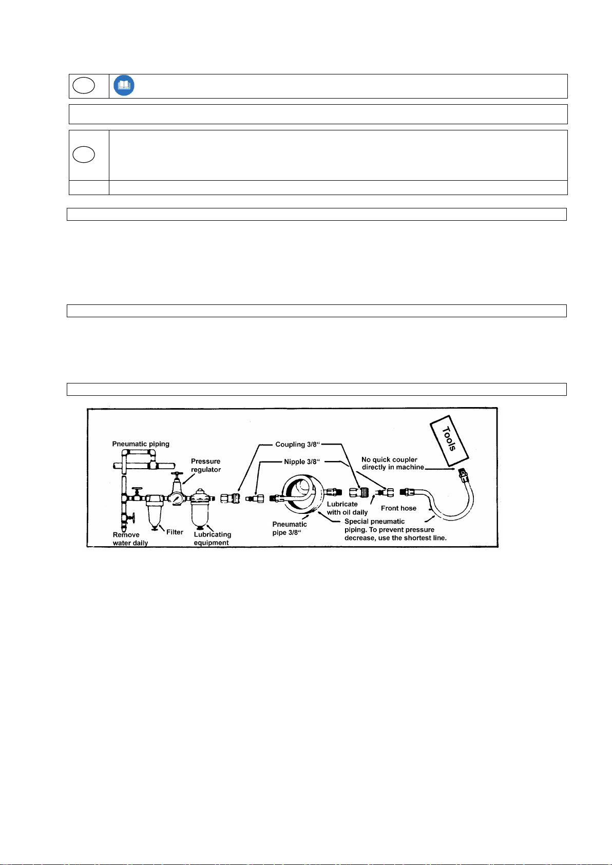
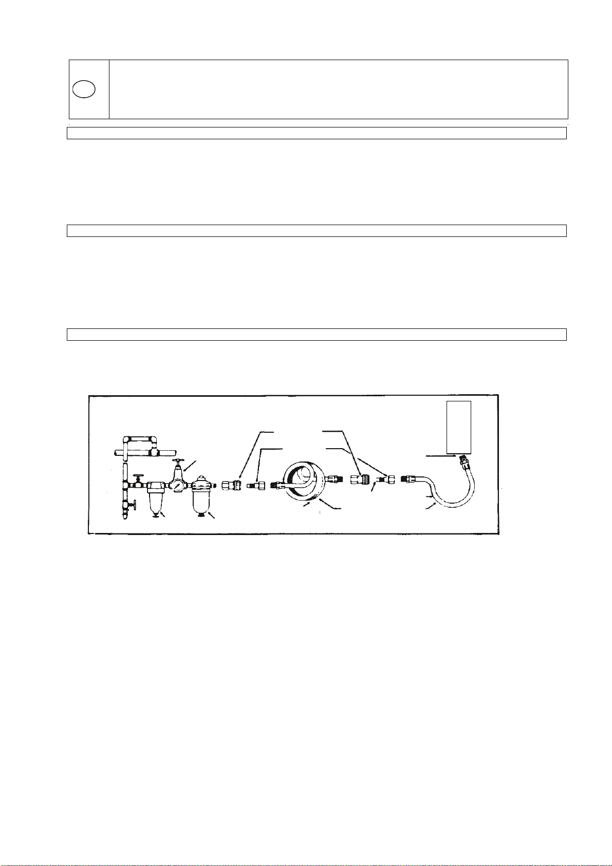
Mise en service et entretien d’outils pneumatiques Güde
Avant de mettre en service votre outil pneumatique, suivez les points suivants:
outils
circuits de pression
purger l’eau
quotidiennement
filtre
régulateur de
pression
huileur
3/8 ‘’ raccord
3/8 ‘’ tubulure de
raccordement
3/8 ‘’ tuyau de pression
embrayage à vitesses
indirectement sur
l’appareil
huiler
quotidiennement
circuits de pression spécial pour
empêcher la baisse de pression,
utilisez, si possible, des circuits
courts
prépompe 3’’
1. Etanchez l’embout de raccordement faisant partie du colis par le ruban de téflon et vissez le sur le raccord d’arrivée pneumatique.
2. N’utilisez l’outil pneumatique qu’avec l’huileur.
3. Une valve de réduction doit se trouver sur le compresseur (tous les compresseurs Güde sont équipés d’une valve de réduction).
4. Montez devant l’huileur un séparateur d’eau (filtre).
5. La pression de travail maximale de votre outil pneumatique s’élève à 6 bars. Si vous réglez la valve de réduction sur plus de 6
bars, une surcharge de l’outil pneumatique peut se produire.
6. Nous conseillons de nettoyez soigneusement et huiler l’outil pneumatique, lors de son inutilisation prolongée. Avant de le
remettre en marche, mettez une petite quantité d’huile pneumatique dans le raccord de l’outil pneumatique, laissez le tournez
brièvement, puis utilisez le avec l’huileur pneumatique. Certains outils sont équipés d’une régulation de rotation continue et d’une
puissance de choc (par ex. clés à choc, perceuse avec marche à gauche/à droite, assortiment de marteaux - burineurs
pneumatiques, ponceuses excentriques, ponceuse oscillante à main etc.). Cette vis de régulation se trouve juste à côté du
raccord d’arrivée d’air de l’appareil.
7. Lors de l’utilisation de la clé à chocs, n’utilisez que des embouts de douilles trempés Güde. Vous pouvez vous les procurer dans
n’importe quel magasin spécialisé. Ceci est aussi valable pour les burins de toutes tailles pour marteaux - burineurs
pneumatiques Güde.
Nous vous souhaitons beaucoup de plaisir avec votre nouvel appareil et vous prionVGHUHVSHFWHUQRVLQVWUXFWLRQVGHJDUDQWLH
Assortiment d‘appareils
17
1 Pistolet pneumatique „Mini“ 16 Aiguille de gonflage de balons
2 Ressort d’arrêt du burin 17 Raccord pour tuyaux 3/8‘’ IG
3 Marteau pneumatique 18 Embout de gonflage
4 Clé à chocs 19 Adaptateur pour gonflage de la chambre à air
5 Affûteuse à barreaux 20 Adaptateur d’aiguilles
6 Clé pneumatique 21 Adaptateur d’embouts de vissage
7 Ass. d’embouts de vissage 22 Ass. de douilles six-pans
8 Ass. de meules 23 Adaptateur 3/8’’/1/2’’
9 Burin 24 Embout de gonflage
10 Cylindres abrasifs 25 Raccord de valve
11 Pointerolle 26 Adaptateur pour gonflage de la chambre à air
12 Burin plat 27 Raccordement d’air comprimé 1/8’’ IG
13 Porte cylindres abrasifs 28 Ass. D’embouts de raccord. d’aire comprimé
14 Ruban de teflon 29 Clé six-pans
15 Flacon d’huile

Garantie
18
La durée de la garantie est de 12 mois en cas d’une
utilisation industrielle et de 24 mois pour le
consommateur final. La période de garantie commence à
courir à compter de la date d’achat de l’appareil.
La garantie s’applique exclusivement sur les défauts de
matériel ou des défauts de fabrication. En cas de
réclamation pendant la durée de la garantie, veuillez
joindre l’original du justificatif d’achat comportant la date
d’achat.
La garantie ne couvre pas une utilisation incompétente,
telle que surcharge de l’appareil, utilisation de force,
endommagement par une personne étrangère ou un objet
étranger, non respect du mode d’emploi et du mode de
montage et usure normale.
Vous avez des questions techniques ? Une réclamation ? Vous avez besoin de pièces détachées ou d’un mode
d’emploi ?
Nous vous aiderons rapidement et sans bureaucratie inutile par l’intermédiaire de nos pages Web www.guede.com dans la
rubrique Service. Aidez-nous pour que nous puissions vous aider. Pour identifier votre appareil en cas de réclamation, nous
avons besoins du numéro de série, numéro de produit et l’année de fabrication. Toutes ces informations se trouvent sur la
plaque signalétique. Pour avoir ces informations toujours à porté de main, veuillez les inscrire ici :
Numéro de série: Numéro de produit: Année de fabrication:
Tél.: +49 (0) 79 04 / 700-360
Fax: +49 (0) 79 04 / 700-51999 E-Mail: support@ts.guede.com
 Loading...