

Page 1

100 GC #20055
140 GC #20046
Deutsch DE 3
Originalbetriebsanleitung
INVERTER
English GB 9
Original Operating Instructions
INVERTER
Français FR 15
Traduction du mode d’emploi d’origine
INVERSEUR
Čeština CZ 22
Originální návod k obsluze
INVERTOR
Slovenčina SK 28
Originálny návod na obsluhu
MENIČ
Nederlands NL 34
Originele gebruiksaanwijzing
OMVORMER
Italiano IT 41
Originale del Manuale d’Uso
INVERTER
Magyar HU 47
Eredeti használati utasítás
INVERTER
Hrvatski HR 53
Prijevod originalnih uputa za uporabu
INVERTER
Slovenščina SI 60
Originalna navodila za uporabo za
INVERTER
Română RO 66
Manual de utilizare original
INVERTER
Български BG 73
Оригинално упътване за работа
ИНВЕРТОР
Bošnjački BA 80
Originalna uputstva za upotrebu
INVERTOR
Türkçe TR 87
Orijinal kullanım kılavuzu
İNVERTER
160 GC #20047
© Güde GmbH & Co. KG - Birkichstrasse 6 - D-74549 Wolpertshausen - Deutschland
Page 2
3
1
2
1
2
1
4
3
3
2
4
6
5
7
1
8
4
Page 3
4
DE
Wir bedanken uns für den Kauf eines Güde Inverter-Schweißgerätes und das von Ihnen entgegengebrachte
Vertrauen in unser Sortiment.
Lesen Sie bitte diese Bedienungsanleitung sorgfältig durch,
bevor Sie das Gerät in Betrieb nehmen !!!
A.V. 2
Nachdrucke, auch auszugsweise, bedürfen der Genehmigung. Technische Änderungen vorbehalten.
Sie haben technische Fragen? Eine Reklamation? Benötigen Ersatzteile oder eine Bedienungsanleitung?
Auf unserer Homepage www.guede.com im Bereich Service helfen wir Ihnen schnell und unbürokratisch weiter. Bitte
helfen Sie uns Ihnen zu helfen. Um Ihr Gerät im Reklamationsfall identifizieren zu können benötigen wir die Seriennummer
DE
sowie Artikelnummer und Baujahr. Alle diese Daten finden Sie auf dem Typenschild. Um diese Daten stets zur Hand zu
haben, tragen Sie diese bitte unten ein.
Seriennummer: Artikelnummer: Baujahr:
Tel.: +49 (0) 79 04 / 700-360
Fax: +49 (0) 79 04 / 700-51999 E-Mail: support@ts.guede.com
Achtung! Wichtiger Hinweis!
Das Gerät erfüllt die Anforderungen der EN 61000-3-11 und unterliegt Sonderanschlußbedingungen. Das heißt, daß eine
Verwendung an beliebigen frei wählbaren Anschlußpunkten nicht zulässig ist.
Das Gerät kann bei ungünstigen Netzverhältnissen zu vorübergehenden Spannungsschwankungen führen.
Das Gerät ist ausschließlich zur Verwendung an Anschlußpunkten vorgesehen, die eine maximale zulässige Netzimpedanz von Z
max
0,233 Ω nicht überschreiten.
Sie müssen als Benutzer sicherstellen, wenn nötig in Rücksprache mit Ihrem Energieversorgungsunternehmen, daß Ihr
Anschlußpunkt, an dem Sie das Gerät betreiben möchten, die oben genannte Anforderung erfüllt.
Gewährleistung
Die Gewährleistung erstreckt sich ausschließlich auf Mängel, die auf Material- oder Herstellungsfehler zurückzuführen sind.
Bei Geltendmachung eines Mangels im Sinne der Gewährleistung ist der original Kaufbeleg mit Verkaufdatum beizufügen.
Von der Gewährleistung ausgeschlossen sind unsachgemäße Anwendungen, wie z. B. Überlastung des Gerätes, Gewaltanwendung,
Beschädigungen durch Fremdeinwirkung oder durch Fremdkörper. Nichtbeachtung der Gebrauchs- und Aufbauanleitung und
normaler Verschleiß sind ebenfalls von der Gewährleistung ausgeschlossen.
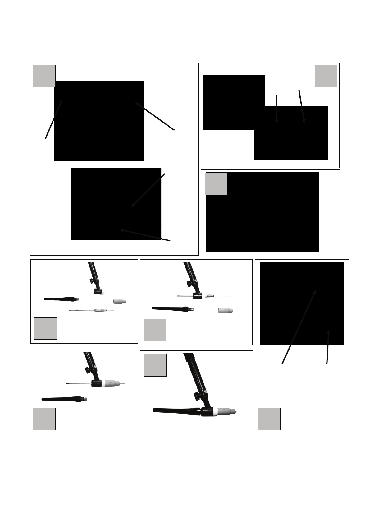
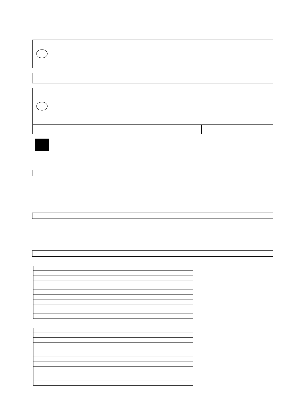
Gerät
Bild 1/Bild 8:
1. Schweißstromregler
2. Massekabel (-)
3. Elektrodenkabel (+)
4. Hauptschalter
Technische Daten
Für Artikel-Nr. 20055 Inverter 100 GC
Anschluss: 230 V~50 Hz
Elektroden: 1,6-2,5 mm
max. Netzleistung: 3,2 kVA
min. Absicherung: 16 A
Leerlaufspannung: 85 V
empf. Materialstärke: 0,8-8 mm
max. Schweißstrom: 100 A
Regelbereich: 10-100 A
ED bei max. Strom: 100A~15% / 55A~60% / 45 A~100%
Schutzart: IP21S
Gewicht: 3,6 kg
Für Artikel-Nr. 20046 Inverter 140 GC
Anschluss: 230V~50 Hz
Elektroden: 1,6-4 mm
max. Netzleistung: 4,7 kVA
min. Absicherung: 16 A
Leerlaufspannung: 80 V
empf. Materialstärke: 0,8-12 mm / WIG 0,5-2mm
max. Schweißstrom: 140 A
Regelbereich: 20-140 A
ED bei max. Strom: 140 A~30% / 100 A~60 % / 90 A~100%
=
Page 4
Isolationsklasse: H
5
Schutzart: IP21S
Gewicht: 6 kg
Für Artikel-Nr. 20047 Inverter 160 GC
Anschluss: 230 V~50 Hz
Elektroden: 1,6-4 mm
max. Netzleistung: 5,6 kVA
min. Absicherung: 16 A
Leerlaufspannung: 80 V
empf. Materialstärke: 0,8-15 mm / WIG 0,5-2 mm
max. Schweißstrom: 160 A
Regelbereich: 20-160 A
ED bei max. Strom: 160 A~20 % / 100 A~60 % / 90 A~100 %
Isolationsklasse: H
Schutzart: IP21S
Gewicht: 7 kg
Allgemeine Sicherheitsmaßnahmen
Die Bedienungsanleitung muß vor der ersten Anwendung des Gerätes ganz durchgelesen werden. Falls über den Anschluss und die
Bedienung des Gerätes Zweifel entstehen sollten, wenden Sie sich an den Hersteller (Service-Abteilung).
Schützen Sie das Gerät vor Feuchtigkeit, Regen und Staub.
UM EINEN HOHEN GRAD AN SICHERHEIT ZU GARANTIEREN, BEACHTEN SIE AUFMERKSAM FOLGENDE HINWEISE:
Der Benutzer ist verantwortlich für die fachgerechte Installation und Nutzung des Geräts, gemäß den Angaben des Herstellers. Wenn
elektromagnetische Störungen festgestellt werden, liegt es in der Verantwortung des Benutzers, diese mit der technischen Hilfe des
Herstellers zu beseitigen. In manchen Fällen ist lediglich eine Erdung der Schweißumgebung erforderlich um die Probleme
abzustellen In anderen Fällen könnte die Errichtung einer elektromagnetischen Schutzwand erforderlich sein, welche die Stromquelle
und die gesamte Arbeitsfläche mit dem angeschlossenen Spannungsfilter umfaßt. Jedenfalls müssen die elektromagnetischen
Störungen so weit heruntergebracht werden, daß sie für den Benutzer nicht mehr störend sind.
Achtung: Aus Sicherheitsgründen darf der Stromkreis nicht geerdet sein. Änderungen der Erdungsvorkehrungen dürfen nur durch
kompetentes, autorisiertes Personal vorgenommen werden, welche die Folgen und Risiken der vorgenommenen Veränderungen
richtig einschätzen können.
Raumanforderungen
Vor der Installation und Inbetriebnahme des Gerätes muß der Benutzer potentielle elektromagnetische Störungen in seinem Umfeld in
Betracht ziehen.
Folgendes ist zu berücksichtigen:
a) Andere Versorgungs-, Kontroll-, Signal- und Telefonkabel über, unter und in der angrenzenden Umgebung des
Schweißgerätes:
b) Radio-, Fernsehgeräte und Receiver;
c) Computer und andere Kontrollgeräte;
d) Sicherheits- und Überwachungsgeräte;
e) Der Gesundheitszustand der anwesenden Personen, z. B. Herzschrittmacher, Hörgeräte usw.
f) Meßgeräte die für die Kalibrierung benutzt werden;
g) Der Schutz der anderen Geräte im Umfeld des Schweißgerätes. Diese müssen kompatibel sein. Hierzu können zusätzliche
Schutzvorkehrungen erforderlich werden;
h) Die Tageszeit, in der die Schweißarbeiten oder andere Arbeiten durchgeführt werden sollen.
Die Größe der zu berücksichtigende Fläche hängt von der Struktur des Gebäudes und von den anderen, zur gleichen Zeit
stattfindenden Aktivitäten ab, sie kann sich sogar bis zu den Nebengebäuden erstrecken.
Emissionsreduzierung
Hauptstromversorgung
Das Schweißgerät muß gemäß den Angaben des Herstellers an der Hauptstromversorgung angeschlossen werden. Wenn Störungen
auftreten, kann es notwendig sein, zusätzliche Vorkehrungen einzurichten, z. B. das Anbringen eines Filters an der
Hauptstromversorgung. Die Stromzuleitungen der fest installierten Schweißgeräte müssen mit einem Isolationsrohr über die ganze
Kabellänge geschützt werden. Die Schweißkabel sollten so kurz wie möglich gehalten werden.
Spezielle Sicherheitshinweise
Einleitung
Lichtbogenschweißgeräte wurden aufgrund jahrelanger Schweisserfahrung entwickelt. Sie gewährleisten neben den sehr guten
Schweißeigenschaften ein hohes Maß an Betriebssicherheit, vorausgesetzt die vom Hersteller vorgegebenen Bedienungsmethoden
werden eingehalten. Aus diesem Grund sollte die Geschäftsleitung unbedingt darauf achten, daß jeder der mit diesem Gerät arbeitet,
die Gelegenheit erhält, diese Informationen zu lesen
Page 5
Allgemeine Vorsichtsmaßnahmen
6
Schutz vor Verbrennungen
Funken, Schlacken, heißes Metall und Strahlen können beim Lichtbogenschweißen Augen und Haut massiv
gefährden. Je näher der Benutzer oder irgendeine andere Person an die Schweißstelle kommt, desto höher ist die
Gefahr, der er sich dieser aussetzt. Vernünftige Schutzkleidung und Schutzausrüstung muß unbedingt vom Benutzer
getragen werden und auch von allen anderen Personen, die in der Nähe des Schweißplatzes arbeiten.
Schutzbrille ist unabdingbar und muß getragen werden um die Augen des Benutzers vor Strahlen, fliegenden Funken und heißem
Metall zu schützen.
Brandschutz
Schweißen äußerst gründlich gereinigt werden.
Schweißen Sie niemals, wenn sich in der Atmosphäre/Luft hohe Konzentrationen von Staub, leicht entzündlichen Gasen und
feuergefährlichen Flüssigkeitsdämpfen (wie z.B. Benzin) befinden.
Nach dem Schweißen müssen Sie sicherstellen, daß die geschweißten Teile abgekühlt sind, bevor sie angefaßt werden oder in
Kontakt mit feuergefährlichen, entzündlichen Materialien kommen
Giftige Rauchgase
Behälter solcher Lösungen und/oder anderen Entfettungsmitteln sind aus der Nähe des Schweißplatzes zu entfernen.
Wenn an beschichteten Metallen, welche Anteile von Blei, Kadmium, Zink, Quecksilber und Beryllium enthalten, Schweißoperationen
durchgeführt werden, können schädliche Konzentrationen von giftigen Rauchgasen entstehen. Angemessene Absaugventilatoren
müssen vorhanden sein oder der Benutzer muß eine Spezialausrüstung tragen, welche die Frischluftzufuhr wie bei einem
Atmungsgerät oder einem mit Luft versorgtem Helm garantiert.
Schweißen Sie keine Metalle, welche mit Materialien beschichtet sind, die giftige Rauchgase entstehen lassen, es sei denn:
Strahlung
Der Lichtbogen kann für die Augen schädlich sein und ist gefährlich bis zu einer Entfernung von 15 Metern (50 Fuß). Niemals sollte
mit bloßen, ungeschützten Augen hineingesehen werden.
Elektrischer Schlag
Die zu schweißenden Teile dürfen nicht berührt oder in der Hand gehalten werden; sowie man den leichtesten elektrischen Schlag
verspürt, muß das Schweißen sofort unterbrochen werden. Bevor das Problem/der Fehler nicht erkannt und von qualifiziertem
Personal behoben wurde, darf die Arbeit nicht wieder aufgenommen werden. Häufiges Kontrollieren der Hauptstromkabel auf
Beschädigungen oder Risse der Ummantelung und sofortiger Wechsel der beschädigten Kabel sind äußerst wichtig. Vor dem
Wechseln der Kabel und Entfernung der Geräteabdeckung ist die Verbindung zwischen Stromversorgungskabel und Hauptleitung zu
unterbrechen. Benutzen Sie das Gerät nie ohne Geräteabdeckungen.
Alle beschädigten Teile sind immer nur durch Original-Ersatzteile zu ersetzen.
Verändern bzw. schließen Sie nie die Sicherheits-Stromunterbrecher kurz und stellen Sie sicher, daß die Stromversorgung durch
einen leistungsfähigen Erdungsstecker ausgestattet ist.
Stellen Sie sicher, daß der Schweißtisch gut geerdet ist.
Jede Wartung darf nur durch qualifiziertes Personal durchgeführt werden. Sind Sie sich des hohen Risikos, bedingt durch die
gefährlichen elektrischen Spannungen, welche beim Arbeiten mit dem Gerät auftreten, bewußt.
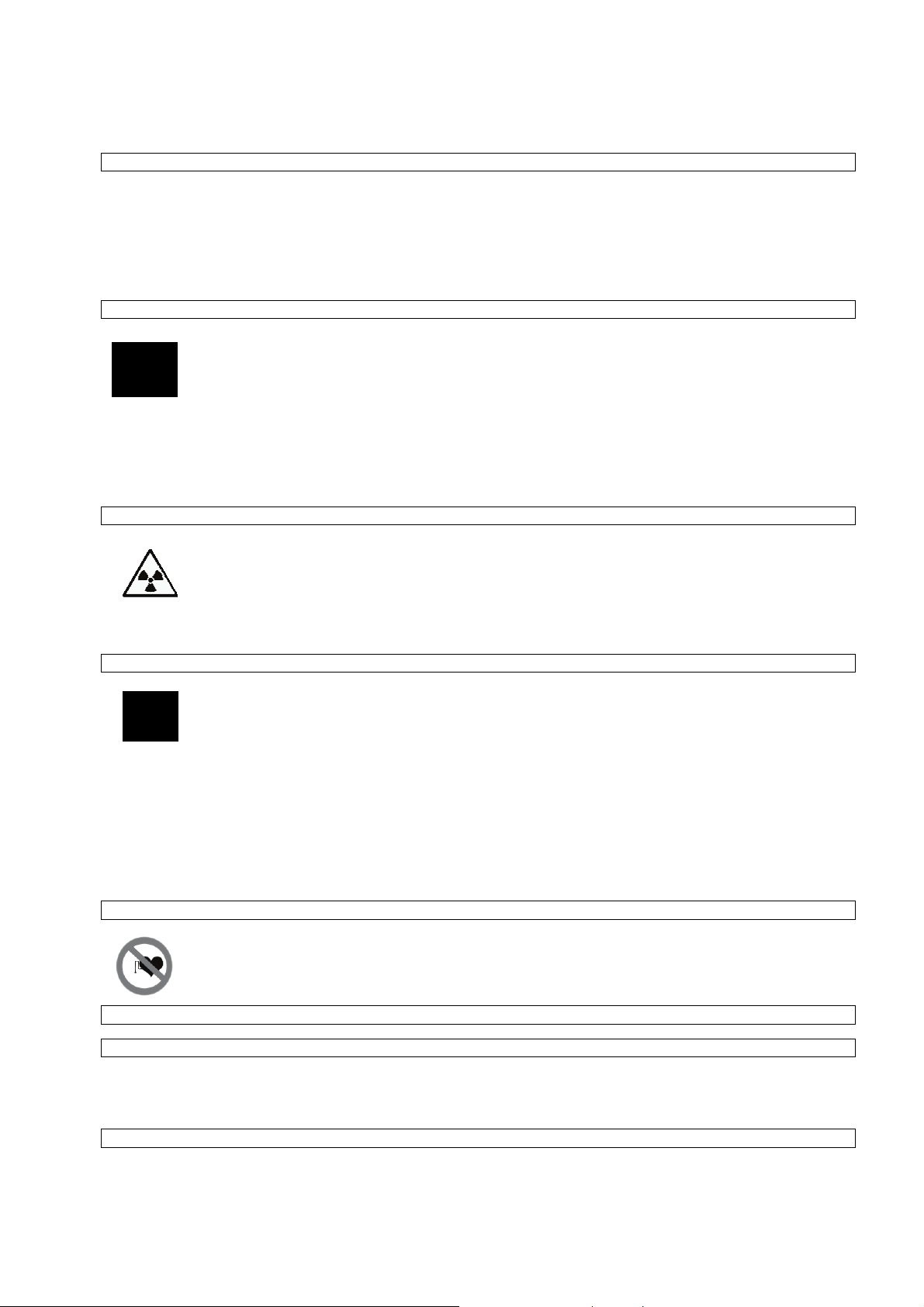
Herzschrittmacher
Schutzhandschuhe (speziell geeignet für das Schweißen) und eine Kopfbedeckung werden ebenso benötigt. Eine
Da beim Elektrolichtbogenschweißen heißes Metall, Funken und Schlacken entstehen, müssen Vorkehrungen zur
Verhütung von Feuer und/oder Explosionen getroffen werden. Es müssen geeignete Feuerlöscheinrichtungen in
unmittelbarer Nähe des Schweißplatzes verfügbar sein. Alle feuergefährlichen Materialien müssen aus der Nähe des
Schweißplatzes entfernt werden. Der Mindestabstand beträgt 10 Meter (35 Fuß). Schweißen Sie niemals leere
Behälter, welche giftige oder möglicherweise explosive Materialien enthielten. Solche Behälter müssen vor dem
Ordnungsgemäße Vorkehrungen sind anzuwenden, um den Schweißer oder andere Personen in der Umgebung
nicht den eventuell giftigen Rauchgasen auszusetzen, welche während des Schweißens möglicherweise erzeugt
werden.
Bestimmte chlorierte Lösungsmittel zersetzen sich unter ultravioletter Strahlung und bilden Phosgengas. Mit diesen
Lösungen sollte vorsichtig umgegangen werden, damit der Kontakt mit den zu schweißenden Teilen vermieden wird.
• Die Beschichtung wurde vor dem Schweißen entfernt. Der Schweißplatz ist ausreichend belüftet.
• Der Schweißer ist mit einer Frischluft-Atemausrüstung ausgestattet
Die beim Schweißen auftretende ultraviolette Strahlung kann schädlich für die Augen sein und die Haut verbrennen.
Es ist deshalb unbedingt erforderlich Schutzkleidung und -helm zu tragen
Kontaktlinsen sollten nicht getragen werden, da die starke Hitze ein Verkleben mit der Hornhaut verursachen kann.
Das beim Schweißen benutzte Schutzschild sollte mit Sicherheitsgläsern (mindestens DIN 10) ausgerüstet sein,
welche bei Bruch oder Beschädigung sofort ausgetauscht werden müssen.
Alle elektrischen Schläge können tödlich sein und deshalb sollten stromführende Kabel und/oder Teile niemals
berührt werden.
Durch das Tragen von isolierenden Handschuhen und Kleidung ist für Isolation vom zu schweißenden Teil und
Erdboden zu sorgen. Kleidungsstücke, wie z.B. Handschuhe, Schuhe, Kopfbedeckungen und Oberkleidung sollten
immer trocken sein und das Arbeiten in feuchten oder nassen Räumen sollte vermieden werden.
Personen, die ein elektronisches Lebenserhaltungsgerät (wie z.B. Herzschrittmacher etc.) tragen, sollten Ihren Arzt
befragen, bevor sie sich in die Nähe von Lichtbogen-, Schneid-, Ausbrenn- oder Punktschweißanlagen begeben, um
Page 6
sicherzustellen, daß die magnetischen Felder in Verbindung mit den hohen elektrischen Strömen ihre Geräte nicht beeinflussen
7
Beschreibung und Produktspezifikation
Einleitung
Die Schweißstromversorgungen der GC-Serie liefern konstanten Strom und sind mit INVERTER Technik konstruiert, mit
Hochleistungs- und Hochzuverlässigkeitsteilen ausgestattet und können für Stabelektroden sowie für WIG Schweißen genutzt werden
Zeichenerklärung
EN 60974-1 Normen
Seriennummer: Serien-Nr., ist bei allen Rückfragen anzugeben
MMA geeignet für das Schweißen mit ummantelter Elektrode
WIG geeignet für das WIG-Schweißen
U
sekundäre Zündspannung
º
X Einschaltdauer-Prozentsatz.
Die Einschaltdauer zeigt den Prozentsatz von 10 Min, in welchem die Stromversorgung bei
gegebenen Strom ohne Überhitzung arbeitet.
I Schweißstrom
U Sekundärspannung mit Schweißstrom 12
U1 Nenn-Netzspannung
1~50/60Hz Einphasenversorgung 50 oder 60 Hz
l1 absorbierter Strom beim entsprechendem Schweißstrom 12. Bei der Stromversorgung für
das WIG Schweißen, dividieren Sie den l1-Wert durch 1,6
IP21 Schutzklasse des Metallrahmens
S geeignet für Arbeiten in Hochrisikobereichen
Thermoschutz
Schutz bei Überhitzung und Hauptversorgungsstörungen
Durch die Intervention der Überwachungseinrichtungen der Netzspannung und der Überhitzung
(Thermoschalter auf den Kühlkörpern) wird die Stromversorgung abgeschaltet.
Installation
Auspacken und Aufstellen
Packen Sie das Gerät aus und untersuchen Sie es gründlich auf Transportschäden. Etwaige Schadensersatzansprüche, die durch
den Transport hervorgerufen wurden, müssen vom Käufer beim Frachtführer geltend gemacht werden. Um das Recht auf
Schadensersatz nicht zu verlieren sollten Sie keine Blankounterschrift leisten, sondern vielmehr sollte ein Vermerk gemacht werden,
daß das Recht auf Schadensersatzansprüche reserviert wird für den Fall, daß nach dem Auspacken Transportschäden entdeckt
werden.
Alle Mitteilungen bezüglich dieses Geräts müssen die Modell- und Seriennummer enthalten, welche sich auf der Rückseite der
Stromversorgung befinden.
Nach dem Auspacken stellen Sie das Gerät an einen gut belüfteten, möglichst staubfreien Platz auf. Achten Sie dabei darauf, daß die
Luftzufuhr neben den Kühlschlitzen nicht versperrt wird.
Warnung: Es ist äußerst wichtig, die Luftzufuhr um das Gerät nicht einzuschränken, weil dies eine Überhitzung des Gerätes zur Folge
haben kann und möglicherweise innere Teile beschädigt werden.
Es sollte mindestens 200 mm freier, uneingeschränkter Platz rund um das Gerät vorhanden sein. Legen Sie keine Filter oder
Abdeckungen vor die Lufteinlaßschlitze der Stromversorgung, da sonst die Garantie erlischt.
Anmerkung: Wenn Sie das Gerät auf der Schulter tragen, muß darauf geachtet werden, daß die Lufteinlaßschlitze nicht versperrt
werden
Installation
Das Gerät muß durch erfahrenes Personal installiert werden. Alle Verbindungen müssen den geltenden Regeln entsprechen, in
völliger Übereinstimmung mit den Sicherheitsvorschriften (CENELEC HD 427)
Allgemeine Anmerkungen
Vor dem Gebrauch dieser Stromversorgung sind die CENELEC Normen HD 407 und HD 433 sorgfältig zu lesen. Die Isolationskabel,
Elektrodenhalteklammer, Stecker und Steckdosen sind zu kontrollieren und es gilt sicherzustellen, daß die Längen und Querschnitte
der Schweißkabel mit dem gewählten Strom vereinbar sind:
bis 5 m Kabellänge: Mindestquerschnitt 16 mm
5 -20 m Kabellänge: Mindestquerschnitt 25 mm
20 -30 m Kabellänge: Mindestquerschnitt 35 mm
2
2
2
Page 7
Inbetriebnahme
8
Beschreibung der Schalttafel
An der Schalttafel befinden sich:
- Stromregelknopf
- Elektroden- und Erdklemmen-Kabelverbindung
- Schweißstrom LED Anzeige (OK wenn an)
- Das gelbe LED-Lämpchen ist im Normalzustand aus. Beim aufleuchten Können folgende Störungen
angezeigt werden:
• Wenn die Netzspannung außerhalb des Bereichs von ± 10 % liegt,
• Wenn das Schweißgerät überlastet wird.
Schweißen mit Mantelelektroden
Das Schweißgerät ist für alle Arten von Elektroden geeignet, und Cellulose Elektroden (AWS 6010). Benutzen Sie
Elektrodenhalteklammern ohne hervorstehende Halterungsschrauben, die den heutigen Sicherheitsstandards entsprechen. Stellen
Sie sicher, daß der Hauptschalter auf der Rückseite auf Position ,,0" gestellt ist bzw. daß das Hauptversorgungskabel nicht in die
Steckdose eingesteckt ist. Verbinden Sie die Schweißkabel, ihrer Polarität entsprechend und nach den Angaben des
Elektrodenherstellers. Der Schweißstromkreis sollte nicht vorsätzlich in direkten oder indirekten Kontakt mit dem Schutzkabel
gebracht werden, es sei denn am Schweißteil.
Wenn die Erdung mit dem Schutzkabel bewußt am Werkstück gemacht wird, muß die Verbindung so kurz wie möglich sein. Der
Querschnitt des Schutzkabels muß mindestens so groß wie der Querschnitt des Schweißstromrückführungskabels sein. Beide Kabel
müssen an der gleichen Stelle am Werkstück angeschlossen werden Benutzen Sie die Erdungsklemme am Gerät oder eine
Erdungsklemme in der Nähe
Alle Vorsichtsmaßnahmen müssen so getroffen werden, um Streustrom zu vermeiden. Prüfen Sie, ob die Netzspannung der
Eingangsspannung des Gerätes entspricht.
Verbinden des Hauptversorgungskabels: Beim Anbringen der Stecker ist auf passende Kapazität zu achten und daß der gelb-grüne
Draht des Hauptkabels mit dem Erdungsstecker verbunden ist. Die Kapazität des Thermomagnetschalters oder der Sicherungen in
der Hauptversorgungsleitung sollte größer oder gleich dem
von dem Gerät absorbierenden Strom l1 sein.
Der absorbierte Strom l1 ist durch das Lesen der technischen Spezifikationen am Gerät entsprechend der
Hauptversorgungsspannung U1 zu bestimmen. Alle Verlängerungskabel müssen den Querschnitt haben, der dem absorbierten Strom
l1 entspricht. Schalten Sie die Stromzufuhr am Hauptschalter an der Geräterückseite ein
WARNUNG: ELEKTRISCHE SCHLÄGE KÖNNEN TÖDLICH SEIN!
BERÜHREN SIE KEINE STROMFÜHRENDEN TEILE!
Der Strom ist entsprechend des Elektrodendurchmessers, der Schweißposition und der zu schweißenden Naht zu wählen. Nach dem
Schweißen ist daran zu denken, den Hauptschalter auszuschalten und die Elektrode aus dem Elektrodenhalter zu entfernen.
Schweißen mit WIG-Ausrüstung / Zubehör: Güde Art.Nr. 41690
Vor Beginn Ihrer Arbeit, muß das entsprechende Gas zur Verfügung stehen.
Fe Stahl ArCO2
Al Aluminium Ar (mit d iesem G erät ni cht möglich)
V2A Edelstahl ArO2
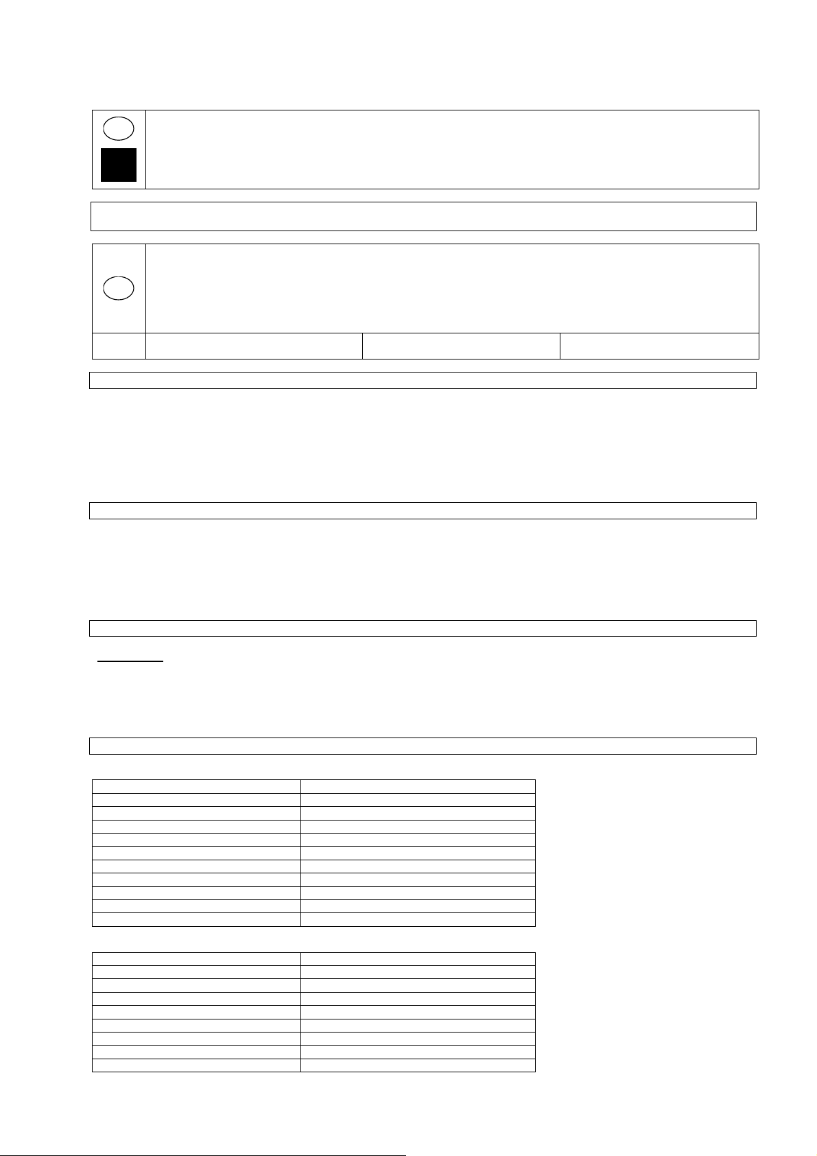
Schließen Sie das Gerät wie folgt an:
- Gasschlauch mittels Schelle an der Gasarmatur der entsprechenden Gasflasche anschließen und mit der WIG-Ausrüstung
verbinden.
- Stecken Sie den Stecker der WIG-Ausrüstung in die entsprechende „Dinse-Buchse“ am Inverter (Minus-Pol).
Achtung: Beim WIG-Schweißen ist das Massekabel der Plus-Pol und das WIG-Paket der Minus-Pol.
- Stecken Sie nun das Massekabel in die entsprechende Buchse (Plus-Pol).
- Schleifen Sie die Wolframnadel senkrecht zur Schleifscheibe spitz an und stecken Sie diese in die Spannzange. Die ca. 5 mm
Wolframnadel sollte vorne aus der Keramikdüse ragen. (siehe Abb. 4-7)
- Öffnen Sie nun das Gasventil am Brenner (ca. ¼ - Umdrehung) und schalten Sie das Gerät auf WIG (falls vorhanden)
- Zünden:
Material, bis der Lichtbogen entsteht. Übung macht den Meister!
Bild 2:
Bild 3:
1. Massekabel (+) Gasschlauch mit Adapter
2. WIG-Brenner (-)
BERÜHREN SIE KEINE SCHWEISSAUSGANGSANSCHLÜSSE, WENN DAS
GERÄT EINGESCHALTET IST!
BERÜHREN SIE NIEMALS DEN SCHWEISSAPPARAT ODER ELEKTRODE UND DIE
ERDKLEMME GLEICHZEITIG!
Setzen Sie nun den Rand der Keramikdüse schräg auf das Material und wippen Sie gleichmäßig die Nadel an das
Page 8

9
EG-Konformitätserklärung
EC Declaration of Conformity
Hiermit erklären wir, Güde GmbH & Co. KG
We herewith declare, Birkichstraße 6, 74549 Wolpertshausen, Germany
Dass die nachfolgend bezeichneten Geräte aufgrund ihrer Konzipierung und
Bauart sowie in der von uns in Verkehr gebrachten Ausführungen den einschlägigen,
grundlegenden Sicherheits- und Gesundheitsanforderungen der EG-Richtlinien
entsprichen.
that the following Appliance complies with the appropriate basic safty and health
requirements of the EC Directive based on its design and type, as brought into
circulation by us.
Bei einer nicht mit uns abgestimmter Änderung der Geräte verliert diese
Erklärung ihre Gültigkeit.
In a case of alternation of the machine, not agreed upon by us, this declaration will
loose its validity.
Bezeichnung der Geräte: - 100 GC, 140 GC, 160 GC
Artikel-Nr.: - 20055
Article-No.: - 20046
- 20047
Einschlägige EG-Richtlinien: - 2004/108/ EC
Applicable EC Directives: - 2006/95/EC
Angewandte harmonisierte
Normen: - EN 60974-10:2003
Applicable harmonized - EN 61000-3-11:2000
Standard - EN 61000-3-2:2000/A2:2005
- EN 60974-1:2005
Datum/Herstellerunterschrift: 03.08.2009
Date/Authorized Signature:
Angaben zum Unterzeichner: Hr. Arnold, Geschäftsführer
Title of Sinatory:
Technische Dokumentation: J. Bürkle; FBL, QS
Page 9

10
GB
supply impedance “Z” at the connection point to the public power supply exceeds 0,233 Ω EN 61000-3-11 it may be
necessary to take further measures before the equipment can be used as intended from this power supply. If necessary, you
can ask your local electricity supply company for the impedance value.
Guarantee
The guarantee solely covers inadequacies caused by material defect or manufacturing defect.
Original payment voucher with the sales date needs to be submitted for any claim in the guarantee period.
The guarantee does not cover any unauthorised use such as appliance overloading, use of violence, damage as a result of any
unauthorised interference or caused by foreign items. Failing to follow the operating and assembly instructions and common wear are
also not included in the guarantee.
Device
figure 1/8
1. Welding current controller
2. Ground cable (-)
3. Electrode cable (+)
4. Main switch
Technical Data
Ordering No. 20055 INVERTOR 100 GC
Supply voltage 230 V~50 Hz
Mains power 3,2 kVA
Minimum Protection 16 A
Maximum welding current 100 A
Idling voltage 85 V
Recommended thickness of material 0,8-8 mm
Electrodes 1,6-2,5 mm
Range of control 10-100 A
Switching time at maximum current 100A~15% / 55A~60% / 45 A~100%
Protection class IP21S
Approximate weight 3,6 kg
Ordering No. 20046 INVERTOR 140 GC
Supply voltage 230V~50 Hz
Mains capacity 4,7 kVA
Minimum protection 16 A
Idling voltage 80 V
Recommended thickness of material 0,8-12 mm / WIG 0,5-2mm
Electrodes 1,6-4 mm
Range of control 20-140 A
Start time at maximum current 140 A~30% / 100 A~60 % / 90 A~100%
Insulation class H
Protection class IP21S
Approximate weight 6 kg
Do you have any technical questions? Claim? Do you need spare parts or instructions for operation?
We are ready to help you quickly and without unnecessary bureaucracy at our site www.guede.com in the part Service.
Please help us in helping you. In order to identify your machine in case of a claim we need its serial number, product number
GB
and year of production. All the data mentioned can be found at the type plate. Please write them down bellow to have them
always handy:
Serial number: Product number: Year of production:
Phone.: +49 (0) 79 04 / 700-360
Given unfavourable conditions in the power supply the equipment may cause the voltage to drop temporarily. If the
!!! Please read this instruction for operation carefully before putting the machine into operation !!!
A.V. 2 Surplus print even in shortened version requires permission.
Technical changes reserved. Illustrations used represent examples.
Fax: +49 (0) 79 04 / 700-51999 E-Mail: support@ts.guede.com
Page 10
Ordering No. 20053 INVERTOR 160 GC
11
Supply voltage 230 V~50 Hz
Mains capacity 5,6 kVA
Minimum protection 16 A
Idling voltage 80 V
Recommended thickness of material 0,8-15 mm / WIG 0,5-2 mm
Electrodes 1,6-4 mm
Range of control 20-160 A
Start time at maximum current 160 A~20 % / 100 A~60 % / 90 A~100 %
Insulation class H
Protection class IP21S
Approximate weight 7 kg
General Safety Measures
It is essential to read the entire operation manual prior to the first use. If there are any doubts arising regarding connection and
operation of the device, consult the manufacturer (servicing department).
Protect the device against moisture, rain and dust.
TO PROVIDE FOR MAXIMUM SAFETY, FOLLOW CAREFULLY THE INSTRUCTIONS BELOW:
The user shall be held liable for professionally done installation and for use of the machine in conformity with the manufacturer’s data.
If the user detects any electromagnetic faults, he is responsible for removing the same and use of the manufacturer’s technical
assistance. In many a case, just grounding the welding area is sufficient to remove the troubles. There are yet other cases, when
developing an electromagnetic screen to cover the current source and the entire working area with a connected voltage filter may be
helpful. In any case, the electromagnetic faults have to be removed so that they are not disturbing the user any more.
Caution: For the sake of safety, the current circuit should not be grounded. Any alteration of the grounding system should be done by
competent authorised personnel able to estimate the consequences and risks of the alterations done.
Location Requirements
Prior to installation and starting the machine up, the user should account for any possible electromagnetic faults in the area.
The factors listed below should be taken into account:
a) other supply, control, signalling and telephone cables above the welding machine and under it and also in the adjacent area
b) radio and TV sets, receivers;
c) computers and other control equipments;
d) safety and monitoring instruments;
e) condition of health of those present, e.g. pacemakers, hearing aids etc.
f) meters used for calibrations;
g) protection of the other instruments and devices in the welding machine area. These devices should be compatible.
Supplementary protection measures may be required.
h) Daytime, in which welding or other works are to be performed.
The area that may produce effects on the welding machine operation is subject to the building structure and other activities being
carried out at a time of welding. The area may be as large as to near the neighbouring buildings.
Emission Reduction
Source Current Supply
As instructed by the manufacturer, the welding machine must be connected to the source current supply. If faults occur, it will be
apparently necessary to provide for supplementary protective measures, such as a filter installed on the lead. The current leads of
fixed welding machines should be protected with an insulation tube along the entire length of the cable. Welding cable should be as
short as possible.
Special Safety Regulations
Introduction
The arc welding machines were developed thanks to many-year experience in the welding profession. Provided that the methods of
operation prescribed by the manufacturer are provided, they will guarantee a high level of operating safety in addition to very good
welding properties. For this reason, the management should take care to ensure that every person working with the machine has
access to this information.
General Precautions
Protection against Burns
Sparkles, clinker, hot metal and radiation may be a serious hazard in arc welding putting eyes and skin at risk. The closer is the user
or another person to the welding site, the bigger is the hazard they are exposed to. The user and any other persons working
adjacently to the welding site should wear adequate protective clothing and personal protective equipment. Protective gloves (special
Page 11
gloves for welding) and a headgear are indispensable. Goggles are essential and must be worn to protect the user’s eyes against
12
radiation, sparkles and hot metal.
Fire Protection
As hot metal, sparkles and clinker are generated by arc welding; precautions must be taken to prevent fire and explosions. Suitable
fire extinguishers must be available in the area of welding site and any fire-hazardous materials should be removed from the area.
The minimum distance of such materials from the welding area should be 10 metres (35 feet). Never weld empty tanks that contained
toxics or explosives. Such tanks have to be cleaned very thoroughly before welding.
Never get down to welding if there are high concentrations of dust, easily inflammable gases and fire-hazardous vapours from liquids
(such as petrol) in the atmosphere/air. Having completed the welding job, take care to cool down the welded parts before anybody
could touch them or before they are in contact with fire-hazardous or ignitable materials.
Toxic Combustion Gases
If you are to weld metals with surface treatment layer containing lead, zinc, mercury and beryllium, remember that these ingredients
may give formation to toxic combustion gases concentrations. The user should have adequate exhaust blowers hand or other special
equipment – breathing apparatus or a helmet with air supply – to provide for fresh air supply.
Never weld metals containing surface treatment layer of materials forming toxic combustion gases. Exceptions are as follows:
Radiation
Electrical arc may be detrimental to the eyes and it is harmful au to the distance of 15 metres (50 feet). Never look in the electrical arc
with unprotected eyes.
Electrical Shock
the problem/fault. Frequent checks of the main cable for damages and cracks of the sheathing are essential and so is instant
replacement of the damaged cables. Before the cable is replaced and the machine enclosure removed, disconnect the supply cable
and main line. Never use the machine without respective housings and enclosures. Parts should be replaced with original spare parts
only.
Never make changes to the safety circuit breaker, do not short circuit it and make sure that the current supply lead is equipped with an
efficient grounding plug.
Provide for good grounding of the worktable for welding.
Only authorised personnel shall perform the maintenance. Mind the high risk related to the hazardous voltage is imminent at work with
the machine.
Pacemakers
Product Description and Specification
Introduction
The welding current supplies series 80 A will supply constant current and they are designed in an INVERTER technique, equipped
with heavy-duty and reliable components and may be used for bar electrodes and for protective atmosphere tungsten electrode
welding.
System Description
The current input and the control logic equipment is mounted on a single main panels in form of special hybrid plates thy may be
easily interchanged. A high degree of reliability is this added and the maintenance and servicing is simplified. The power module
includes INVERTER working at frequency above 80 kHz and a very low resonance time (500 milliseconds). The result of this
Precautionary measures have to be taken for the welder or other persons not to be exposed to any toxic combustion
products that may be generated by welding.
Certain chlorinated solvents decompose by action of ultraviolet radiation and forms phosgene. These solvents should
be handled with care to prevent any contact with the welded parts. Containers with these solvents and/or other
degreasing agents should be removed from the welding area.
• The surface layer was removed prior to welding. The welding area is sufficiently ventilated.
• The welder has the breathing apparatus with air supply available.
UV radiation arising from welding may be harmful to the eyes and may cause burns of the skin. Therefore, protective
clothing and a helmet should be worn.
Never wear contact lenses when welding because the strong glow may cause them sticking to the cornea.
The protective shield used at welding should have safety glass (DIN 10 as a minimum). If the glass gets damaged or
cracked it should be replaced immediately.
Any electrical shock may be fatal. For this reason, never touch conductive cables and /or parts.
You will get isolated from the welded part by wearing insulation gloves and clothing. Parts of your clothing like
gloves, boots, headgear and outerwear should be always dry. Avoid any work in moist or wet areas.
Do not touch the welded parts and do not hold them with your hand either; as soon as you feel the electrical shock,
however small, stop welding immediately. Do not resume the work until an authorised person diagnoses and clear
The persons with any electronic life-supporting apparatus (such as pacemaker) should consult a physician before
getting exposed to the effects of welding machines - arc welding, cutting or burning or tack welding for them to be
sure that the magnetic field combined with the high electric current values would not produce and damaging effects
on their apparatuses.
Page 12
equipment is very even welding and simple start, homogenous-sized drops and better weld penetration.
13
Technical Symbols Glossary
EN 60974 International standards
Seriennummer Series Number – please quote with any inquiries
MMA good for sheathed electrode welding
WIG good for protective atmosphere tungsten electrode welding
U
secondary ignition voltage
º
X Start time - percentage rate.
Start time shows the percentage rate out of 10 minutes, within which the current input at a given current value
works without overheating.
I Welding current
U Secondary voltage with welding current 12
U1 Rated mains voltage
1~50/60Hz Single-phase supply 50 or 60 Hz
l1 Absorbed current with respective welding current 12. When the current for welding is supplied by the tungsten
electrode in protective atmosphere divide the value of l1 by 1.6
IP21 Metal frame protection class
S Good for work in high-hazardous areas
Thermal Protection
Overheat Protection and Protection against Principal Current Supply Fault
The current supply will turn off in result of intervention of the mains voltage control equipment and in result of overheating (thermal
switch on cooling elements).
Installation
Unpacking and Installation
Unpack the machine and inspect it thoroughly to see whether it was not damaged at transport. The claims for damages, if any, should
set up with the carrier. For you not to loose the right for damages, do not sign any blank documents or you may state in a note that
you reserve the right to claim damages for case that after unpacking damages inflicted by transport are revealed.
Any notices regarding the machine should quote the model and the series number to be found on the current input rear side.
Having unpacked, install the machine in a well-ventilated area free of any dust, if possible. Take care to prevent blocking the air
supply next to the cooling slots.
Warning: It is essential not to restrict the air supply around the machine as that might result in overheating and subsequently
damaging some of the inside components.
A minimum of 200 mm of free space should be preserved around the machine. Do not put filters and covers in front of ventilation
opening, the warranty-based claims would become void.
Note: If you carry the machine on your shoulder, take care not to block the ventilation openings.
Installation
Only experienced personnel should install the machine. Any connections have to be in compliance with effective rules and in full
conformity with safety regulations (CENELEC HD 427).
General Notes
Prior to using this current supply, read carefully CENELEC HD 407 and HD 433 standards. Insulation cables, electrode holding clips,
plugs and sockets should be checked to see whether length and cross sections of welding cables correspond to the selected
current:
Cable length up to 5 m : minimum cross section 16 mm
Cable length 5 - 20 m : minimum cross section 25 mm
Cable length 20 - 30 m : minimum cross section 35 mm
2
2
2
Start up
Control Panel Description
Following elements are placed on the control panel:
1. Current control knob
2. Electrodes and grounding terminals cable connections
3. Welding current indicating LED (OK if on)
4. Normally, yellow LED is off. When it goes on, it may signal following faults:
Page 13

• Mains voltage different by more than ± 10%.
14
• Welding machine overloaded.
Sheathed Electrode Welding
The welding machine can be used with any electrodes, the cellulose electrodes (AWS 6010) included. Use electrode-holding clips
without any protruding lock screws in compliance with the current safety standards. Make sure that the main switch on the rear side is
in position,,0" or the main supply cable is not plugged in. Connect the welding cables to their polarity and in conformity with the
electrode manufacturer’s data. Welding current circuit should avoid any direct or indirect contact with the protective cable, except for
contact on the welded piece.
If grounding is deliberately done using the protective cable on the welded piece, the connection has to be as short as possible. The
protective cable cross-section has to be equal to that of the reverse welding cable as a minimum. Both the cables should be
connected to the welding piece at the same point. Use the grounding terminal on the machine or a grounding terminal nearby.
Any precautionary measures should be taken to prevent stray currents. Check that the mains voltage is corresponding to the machine
input voltage.
Main supply cable connection: When mounting the plug, care has to be taken to have the corresponding capacity and the main cable
yellow-green conductor being connected to the grounding plug. The capacity of thermal magnetic switch or fuses of the main supply
line should be more or equal to the machine- absorbed current I1.
The absorbed current l1 may be determined upon having read all the technical specifications on the machine according to main input
voltage U1. The cross section of any extension cables should correspond to the absorbed current l1. The current supply shall be
switched on using the main switch on the machine rear side.
WARNING: ELECTRIC SHOCKS MAY BE FATAL!
DO NOT TOUCH ANY CONDUCTIVE PARTS!
NEVER TOUCH THE WELDING MACHINE OR ELECTRODE AND THE
GOUND TERMINAL AT A TIME!
Select the current subject to the electrode diameter, welding position and the welding seam. With welding completed, keep in mind
that the main switch has to be turned off and the electrode removed from the holder.
Welding with WIG equipment (for tungsten welding in protective atmosphere): ordering no. Güde 41690.
Caution! It is not possible with ordering no. 20045, 20054!
Before getting down to work, make sure that the right gas is available.
Fe steel ArCO2
Al aluminium Ar (not possible with this device)
V2A premium steel ArO2
Connecting the device, proceed as described below:
- Connect the gas hose to the gas fitting on the corresponding bottle using a clip and connect to the WIG equipment.
- The WIG equipment plug connects to the corresponding socket „Dinse“ on the inverter (negative pole).
Caution: At WIG-welding (using a tungsten electrode in protection atmosphere), the grounding cable is the positive pole
and the WIG package is the negative pole.
- Now, plug the grounding cable in a corresponding socket (positive pole).
- Sharpen the tungsten needle in perpendicular direction to the grinding wheel and insert it in the clamp. Ca 5 mm of the tungsten
needle should protrude from the ceramic nozzle in the front. (see Fig. 1-4).
- Now, turn the burner gas valve on (ca ¼ turn) and switch the device on WIG (if available)
- Lighting:
arc is formed.
Practice makes perfect!
figure 2
1. Electrode cable (+)
2. Ground cable (-)
figure 3
Hose with adapter
DO NOT TOUCH ANY WELDING CONNECTION OUTLETS WHEN THE MACHINE IS ON!
Now, set the ceramic nozzle edge sideward to the material and swing the needle close the material until the electric
Page 14
15
EG-Konformitätserklärung
EC Declaration of Conformity
Hiermit erklären wir, Güde GmbH & Co. KG
We herewith declare, Birkichstraße 6, 74549 Wolpertshausen, Germany
Dass die nachfolgend bezeichneten Geräte aufgrund ihrer Konzipierung und
Bauart sowie in der von uns in Verkehr gebrachten Ausführungen den einschlägigen,
grundlegenden Sicherheits- und Gesundheitsanforderungen der EG-Richtlinien
entsprichen.
that the following Appliance complies with the appropriate basic safty and health
requirements of the EC Directive based on its design and type, as brought into
circulation by us.
Bei einer nicht mit uns abgestimmter Änderung der Geräte verliert diese
Erklärung ihre Gültigkeit.
In a case of alternation of the machine, not agreed upon by us, this declaration will
loose its validity.
Bezeichnung der Geräte: - 100 GC, 140 GC, 160 GC
Artikel-Nr.: - 20055
Article-No.: - 20046
- 20047
Einschlägige EG-Richtlinien: - 2004/108/ EC
Applicable EC Directives: - 2006/95/EC
Angewandte harmonisierte
Normen: - EN 60974-10:2003
Applicable harmonized - EN 61000-3-11:2000
Standard - EN 61000-3-2:2000/A2:2005
- EN 60974-1:2005
Datum/Herstellerunterschrift: 03.08.2009
Date/Authorized Signature:
Angaben zum Unterzeichner: Hr. Arnold, Geschäftsführer
Title of Sinatory:
Technical Documentation: J. Bürkle; FBL, QS
Page 15
16
FR
Modifications techniques réservées. Les représentations figurant dans le mode d’emploi sont à titre d’exemple.
reseau Z sur le point de raccordement au reseau public est superieur a 0,233 Ω EN 61000-3-11 d’autres mesures peuvent
etre necessaires avant que l’appareil ne puisse etre exploite sur ce raccord conformement a l’affectation. Si necessaire,
demandez l’impedance a l’entreprise distributrice d’energie electrique locale.
Garantie
La garantie concerne exclusivement les imperfections provoquées par le défaut du matériel ou le défaut de fabrication.
En cas de réclamation pendant la durée de la garantie, il est nécessaire de joindre l’original du justificatif d’achat avec la date d’achat.
La garantie n’inclut pas une utilisation incompétente telle que surcharge de l’appareil, utilisation de la force, endommagement par
intervention étrangère ou objets étrangers. Le non respect du mode d’emploi et du mode de montage ainsi que l’usure normale ne
sont pas non plus inclus dans la garantie.
Soudeuse à inverseur
Fig. 1/8
1. Régulateur du courant de soudage
2. Câble de de mesurage (-)
3. Câble d´électrode (+)
4. Principal
Données techniques
Pour le produit numéro: 20055 INVERTER 100 GC
Connexion 230 V~50 Hz
Puissance de réseau 1,6-2,5 mm
Protection min. 3,2 kVA
Courant de soudage max. 16 A
Tension de marche à vide 85 V
Epaisseur du matériau rec. 0,8-8 mm
Electrodes 100 A
Gamme de réglage 10-100 A
ED avec courant max. 100A~15% / 55A~60% / 45 A~100%
Classe d´isolement IP21S
Poids approx. 3,6 kg
Pour le produit numéro: 20046 INVERTER 140 GC
Connexion 230V~50 Hz
Puissance de réseau 1,6-4 mm
Protection min. 4,7 kVA
Courant de soudage max. 16 A
Tension de marche à vide 80 V
Epaisseur du matériau rec. 0,8-12 mm / WIG 0,5-2mm
Electrodes 140 A
Gamme de réglage 20-140 A
ED avec courant max. 140 A~30% / 100 A~60 % / 90 A~100%
Classe d´isolement H
Type de protection IP21S
Poids approx. 6 kg
Vous avez des questions techniques ? Une réclamation ? Vous avez besoin de pièces détachées ou d’un mode
d’emploi ?
Nous vous aiderons rapidement et sans bureaucratie inutile par l’intermédiaire de nos pages Web www.guede.com dans la
rubrique Service. Aidez-nous pour que nous puissions vous aider. Pour identifier votre appareil en cas de réclamation, nous
FR
avons besoins du numéro de série, numéro de produit et l’année de fabrication. Toutes ces informations se trouvent sur la
plaque signalétique. Pour avoir ces informations toujours à porté de main, veuillez les inscrire ici :
Numéro de série: Numéro de produit: Année de fabrication:
Tél.: +49 (0) 79 04 / 700-360
L’appareil peut entrainer des baisses de tension provisoires lorsque le reseau n’est pas favorable. Si l’impedance de
!!! Avant de mettre l’appareil en marche, veuillez lire attentivement ce mode d’emploi!!!
A.V. 2 Toute réimpression, même partielle, nécessite une approbation.
Fax: +49 (0) 79 04 / 700-51999 E-Mail: support@ts.guede.com
Page 16
17
Pour le produit numéro: 20047 INVERTER 160 GC
Connexion 230 V~50 Hz
Puissance de réseau 1,6-4 mm
Protection min. 5,6 kVA
Courant de soudage max. 16 A
Tension de marche à vide 80 V
Epaisseur du matériau rec. 0,8-15 mm / WIG 0,5-2 mm
Electrodes 160 A
Gamme de réglage 20-160 A
ED avec courant max. 160 A~20 % / 100 A~60 % / 90 A~100 %
Classe d´isolement H
Type de protection IP21S
Poids approx. 7 kg
Mesures de sécurité générales
On doit inconditionnellement lire ce mode d´emploi-ci avant le premier emploi de la soudeuse à inverseur. En cas de doutes quant à
la connexion et quant au service de l´appareil il faut consulter le producteur (son centre de service).
Protégez la soudeuse contre l´humidité, contre la pluie ainsi que contre la poussière. .
POUR POUVOIR GARANTIR UN HAUT NIVEAU DE SÉCURITÉ OBSERVEZ ATTENTIVEMENT LES INSTRUCTIONS
SUIVANTES:
L´utilisateur est responsable de l´installation professionnelle ainsi que de l´utilisation professionnelle de la soudeuse, selon les
dispositions du producteur. En cas de la détermination des perturbations électromagnétiques c´est l´utilisateur qui est responsable de
leur élimination, avec l´aide technique du producteur. Quelquefois, on peut éliminer les problèmes seulement par la mise de
l´environnement de soudage à la terre. Dans certains cas, il faut établir un mur de protection électromagnétique qui contient la source
du courant et toute la surface de travail avec le filtre de tension accouplé. Mais, en tout cas, les perturbations électromagnétiques
doivent être réduites au niveau qui n´est pas perturbateur pour l´utilisateur.
ATTENTION: pour des raisons de sécurité le circuit ne doit pas être mis à la terre. Toutes les modifications des mesures de sécurité
peuvent être effectuées exclusivement par les personnes y autorisées, qui sont capables d´évaluer correctement les risques de telles
modifications.
Demandes spatiales
Avant l´installation et la mise de la soudeuse en marche l´utilisateur doit prendre en considération les perturbations
électromagnétiques potentielles dans son champ.
Il faut prendre en considération les points suivants:
a) Les autres câbles d´alimentation, de commande, de signalisation et téléphoniques situés au-dessus et sous la soudeuse ainsi
que lesquels installés dans l´environnement adjacent.
b) Les postes et les récepteurs de radio, de télévision.
c) Les computers et les autres appareils de commande.
d) Les dispositifs de protection ainsi que tous les autres dispositifs de surveillance.
e) L´état de santé des personnes présentes, par exemple les stimulateurs du coeur, les moyens acoustiques etc.
f) Les instruments de mesurage utilisés pour le calibrage.
g) Les moyens de protection des autres appareils dans le champ de la soudeuse. Ils doivent être compatibles. Peut-être, il faudra
prendre les mesures de protection supplémentaires.
h) Le temps du jour où on veut effectuer les travaux de soudage ou les autres travaux.
La grandeur de la surface qu´on doit prendre en considération, dépend de la structure du bâtiment ainsi que des autres activités
effectuées dans le lieu en question en même temps, elle peut s´étendre jusqu´aux bâtiments adjacents.
Réduction des émissions
Alimentation principale
La soudeuse doit être connectée à l´alimentation principale selon les instructions du producteur. En cas des défauts il faut prendre les
mesures supplémentaires, par exemple l´installation du filtre à l´alimentation principale. Les conducteurs d´arrivée des soudeuses qui
sont installés à fixe, doivent être munis d´un tuyau d´isolement le long de la longueur entière du câble. Les câbles de soudage
devraient être les plus courts possible.
Instructions de sécurité spéciales
Introduction
Les soudeuses à l´arc électrique ont été mises au point sur la base de l´expérience de longues années en matière du soudage. Elles
garantissent, outre les très bonnes propriétés de soudage, aussi un haut niveau de sécurité de service si on observe les méthodes
d´emploi déterminées par le producteur. Pour les raisons susdites, la direction de la firme doit inconditionnellement assurer que
chaque personne qui travaille avec la soudeuse, ait l´occasion de lire ces informations-ci.
Page 17
Mesures de sécurité générales
18
Protection contre brûlures
Les étincelles, la scorie, le métal chaud ainsi que le rayonnement peuvent compromettre, pendant le soudage à l´arc
électrique, les yeux et la peau d´une façon très massive. Plus près est l´utilisateur ou une autre personne du poste
de soudage, plus fort est le danger de l´exposition. Inconditionnellement, l´utilisateur (ainsi que chaque autre
personne qui travaille ou se trouve à proximité du poste du soudage) doit porter le vêtement et l´équipement de
tête. Absolument inconditionnellement, il faut porter les lunettes de protection pour protéger les yeux de l´utilisateur du
rayonnement, des étincelles et du métal chaud.
Protection de l´incendie
ou, même si seulement peut-être, explosifs. Si vous voulez les souder, avant le soudage, il faut les nettoyer exceptionnellement
solidement et attentivement.
Jamais, ne soudez quand il y a de hautes concentrations de la poussière, des gaz qui sont facilement inflammables, et/ou des
effluves de liquides dangereux en relation avec l´ incendie (par exemple d´essence) dans l´atmosphère/dans l´air. Le soudage fini,
vous devez laisser les parties soudées refroidir avant de les toucher ou avant leur contact avec les matériaux dangereux quant à
l´incendie, inflammables.
Résidus de combustion toxiques
proximité du poste du soudage.
Si vous voulez effectuer les travaux de soudage sur les métaux revêtus, qui contiennent les parts de plomb, de cadmium, de zinc, de
mercure et de béryllium, vous pouvez causer la genèse des concentrations nuisibles des résidus de combustion. Il faut avoir à la
disposition les ventilateurs d´exhaustion opportuns ou l´utilisateur doit porter un équipement spécial garantissant une arrivée de l´air
frais comme, par exemple, en cas d´un respirateur ou d´un casque muni de l´arrivée de l´air.
Ne soudez pas les métaux qui sont revêtus des matériaux qui causent la genèse des résidus de combustion toxiques, si vous voulez
tout de même effectuer leur soudage, vous devez:
- enlevez le revêtement avant de commencer le soudage. Le poste du soudage doit être suffisamment ventilé.
- Le soudeur doit être muni de l´équipement de respiration à air frais.
Rayonnement
L´arc électrique peut être nuisible pour les yeux en étant dangereux jusqu´ à la distance de 15 m (50 pieds). Ne regardez-y jamais
avec les yeux nus, sans protection.
Choc électrique
Jamais, ne touchez les parties à souder et ne les jamais tenez à la main. Quand vous sentez, même si le plus léger, choc électrique,
vous devez immédiatement interrompre le travail de soudage. Vous ne devez pas reprendre le travail de soudage jusqu´à
l´élimination du problème/du défaut en question. Il faut effectuer les contrôles fréquents des câbles d´alimentation quant aux
détériorations ou fissures du revêtement – en cas d´une détérioration, effectuez immédiatement le remplacement – très important!
Avant le remplacement des câbles et avant l´enlèvement des couvercles et des protections de la soudeuse, il faut couper la
connexion entre le câble d´alimentation et la ligne principale. N´utilisez jamais la soudeuse sans couvercles et protections.
Toutes les parties endommagées doivent toujours être remplacées par les pièces détachées originales.
Jamais, ne modifiez ou, éventuellement, n´accouplez la soudeuse à court, l´alimentation doit tours être munie d´une agrafe de mise à
la terre puissante.
La table de soudage doit toujours être bien mise à la terre.
Chaque travail de maintenance doit être effectué exclusivement par le personnel y qualifié. Toujours, il faut se rendre compte du haut
risque dû aux tensions électriques fortes qui se produisent pendant le travail avec votre soudeuse.
protection opportun. Aussi, il faut porter les gants de protection (spécials pour le soudage) et une protection de la
Parce que le soudage à l´arc électrique est accompagné de la genèse du métal chaud, des étincelles et de la scorie, il
faut inconditionnellement prendre les mesures opportunes pour garantir la prévention des incendies et/ou des
explosions. Les dispositifs d´extinction opportuns doivent être à la disposition à proximité immédiate du poste du
soudage. Tous les matériaux dangereux quant à l´incendie doivent être enlevés de proximité du poste du soudage.
L´intervalle minimal fait 10 m (35 pieds). Ne soudez jamais les récipients vides qui ont contenu les matériaux toxiques
Il faut prendre les mesures opportunes pour ne pas exposer le soudeur ou une autre dans son environnement à
l´effet des résidus de combustion, éventuellement, toxiques, qui peuvent se produire pendant le soudage.
Certains dissolvants de chlore se décomposent dans les rayons ultraviolets en formant le gaz de phosgène. On doit
travailler très attentivement avec ces dissolvants-ci, il faut inconditionnellement prévenir et éliminer leur contact avec
les parties à souder. Il faut enlever tous les récipients de ces dissolvants-ci et/ou de tous les autres dégraissants de
Les rayons ultraviolets qui se produisent pendant le soudage peuvent être nuisibles pour vos yeux et peuvent brûler
votre peau. Pour cela il faut inconditionnellement porter un vêtement et un casque de protection.
Ne portez pas les lentilles cornéennes – la chaleur forte peut causer leur collage avec la cornée.
Le bouclier protecteur usé pendant le soudage devrait être muni de verres du protection (DIN 10 au minimum) qui,
en cas de chaque casse ou détérioration, doivent être immédiatement remplacés.
Chaque choc électrique peut être mortel – pour cela, tous les câbles et/ou toutes les parties de courant ne doivent
jamais être touchés/touchées.
Il faut assurer l´isolement de la partie à souder et de la terre par le portage des gants et des vêtements isolants. Les
pièces de vêtement, par exemple les gants, la chaussure, les casques et le vêtement de dessus doivent toujours
être sècs, il faut aussi éliminer le travail dans les lieux humides ou mouillés.
Page 18
Stimulateur du coeur
19
Les personnes qui portent un appareil médical électronique (par exemple un stimulateur du coeur, etc.), doivent
consulter leur médicine avant d´arriver à proximité des dispositifs de soudage à l´arc électrique, de coupage par
soudage, de perçage par soudage et/ou de soudage par points – vous devez être absolument sûrs que les champs
magnétiques n´influencent pas vos appareils médicals.
Description et spécification du produit
Introduction
Les sources du courant de soudage de la série 80 A fournissent un courant constant et sont construits avec la technologie
INVERSEUR, elles sont munies des parties de haute puissance et de haute fiabilité, on peut les utiliser pour les électrodes à barre
ainsi que pour le soudage WIG.
Description du système
La source du courant et montée, avec la logique de commande, sur les tableaux hybrides séparés (on peut les substituer
mutuellement) installés sur un seul tableau principal. Ainsi, le système atteint un haut niveau de fiabilité en facilitant aussi les travaux
de maintenance et le service de client. Le module énergétique contient un INVERSEUR travaillant avec une fréquence au-dessus de
80 kHZ et avec un temps de résonance très bas (500 millisecondes). Ainsi, on atteint un soudage extrêmement uniforme avec un
start simple, avec la grandeur des gouttes homogène, avec une meilleure pénétration et avec une présence des perles sans
problèmes.
Explication des signes techniques
EN 60974 internationales-ci.
Seriennumer : Le numéro de série, il faut le mentionner en cas de toutes les questions.
MMA Opportun pour le soudage avec l´électrode à enrobage
WIG Opportun pour le soudage WIG
U
Tension d´allumage secondaire
º
X Pourcentage de la durée du start.
La durée du start indique le pourcentage de 10 min. pendant lequel la source du courant travaille, avec le courant
déterminé, sans surchauffe.
I Le courant de soudage.
U La tension secondaire avec le courant de soudage 12.
U1 Tension de réseau nominale.
1~50/60Hz La source monophasée de 50 ou 60 Hz.
l1 Le courant absorbé avec le courant de soudage 12 correspondant. En cas de la source du courant pour le
soudage WIG, vous devez divisez la valeur I1 par 1,6.
IP21 La classe de protection du bâti métallique.
S Opportun pour le travail dans les zones de haut risque.
Protection thermique
Protection en cas d´une surchauffe et des défauts de l´alimentation principale
La source d´alimentation est coupée par l´intervention des dispositifs de surveillance de la tension de réseau et de la surchauffe
(commutateur thermique sur les corps de refroidissement).
Installation
Déballage et mise
Déballez la soudeuse et contrôlez-la attentivement quant aux détériorations éventuelles dues au transport. Le client doit faire valoir
toutes ses prétentions de l´indemnisation dues au transport chez le transporteur. Pour ne pas perdre le droit de l´indemnisation, vous
ne devriez pas faire une signature en blanc, faites mieux une note que le droit de prétentions de l´indemnisation est réservé pour le
cas qu´on détecte, après le déballage, les détériorations dues au transport.
Toutes les communications quant à la soudeuse doivent porter le numéro de modèle ainsi que lequel de série qui se trouvent au
derrière de la source du courant.
Après le déballage, posez votre soudeuse dans un lieu bien ventilé, si possible, sans chaque poussière. L´arrivée de l´air à côté des
fentes de refroidissement ne doit pas être obstruée!
Attention: L´arrivée de l´air autour de la soudeuse ne doit pas être limitée – cela pourrait mener à une surchauffe de l´appareil en,
peut-être, endommageant certaines parties internes. Vous devez avoir, au minimum, 200 mm de l´espace libre, illimité, autour de la
soudeuse. Ne posez aucuns filtres devant les fentes de l´arrivée de l´air de la source du courant, autrement, la garantie devient nulle.
Remarque: Si vous portez la soudeuse sur les épaules, les fentes de l´arrivée de l´air ne doivent pas être obstruées.
Installation
La soudeuse doit être installée par un personnel qualifié et expérimenté. Tous les raccordements doivent correspondre aux règles en
vigueur, en conformité complète avec les règles de sécurité (CENELEC HD 427).
Page 19
Remarques générales
20
Avant l´utilisation de cette source du courant-ci, on doit lire, très attentivement, les normes CENELEC HD 407 et HD 433. Les câbles
d´isolement, les agrafes d´électrode, les fiches ainsi que les prises doivent être contrôlés/contrôlées, on doit assurer que les
longueurs et les coupes transversales des câbles de soudage soient compatibles avec le courant choisi:
jusqu´à 5 m longueur du câble: coupe transversale au minimum 16 mm
5 -20 m longueur du câble: coupe transversale au minimum 25 mm
20 -30 m longueur du câble: coupe transversale au minimum 35 mm
2
2
2
Mise en marche
Description des tableaux de distribution
Sur le tableau de distribution, vous pouvez trouves les parties suivantes:
1. Le bouton de réglage du courant
1. Le raccordement de câbles des électrodes et des agrafes de mise à la terre
3. L´indicateur LED du courant de soudage (OK, s´il luit)
4. A l´état normal, la lampe jaune ne luit pas. Si elle luit, les défauts suivants peuvent être indiqués:
• la tension de réseau se trouve hors de la limite de ± 10%,
• la soudeuse est surchargée.
Soudage avec électrodes à enrobage
La soudeuse est opportune pour tous les types des électrodes et pour les électrodes à cellulose (AWS 6010). Utilisez agrafes
d´électrodes sans vis de fixation saillantes qui sont en conformité avec les normes en vigueur. Assurez que le commutateur principal
au derrière soit à la position „0“, éventuellement, que le câble d´alimentation principal ne soit pas mis dans la prise. Connectez les
câbles selon leur polarité et selon les données et instructions du producteur des électrodes. Le circuit du courant de soudage ne
devrait pas mis intentionnellement en contact direct ou indirect avec le câble de protection, c´est à dire seulement avec la partie
soudée.
Si vous faites la mise à la terre avec le câble de protection intentionnellement à la pièce soudée, la connexion doit être la plus courte
possible. La coupe transversale du câble de protection doit avoir, au minimum, la grandeur de la coupe transversale du câble
rétroactif du courant de soudage. Tous les deux câbles doivent être connectés dans le même lieu à la pièce soudée. Utilisez une
agrafe de mise à la terre sur l´appareil ou une agrafe à proximité. On doit prendre toutes les mesures de sécurité pour éliminer le
courant errant. Contrôlez si la tension de réseau correspond à la tension d´admission de l´appareil.
La connexion du câble d´alimentation principal: pendant l´installation des fiches on doit veiller à la capacité opportune. Le fil jaune-vert
du câble principal doit être couplé avec les fiches de mise à la terre. La capacité du commutateur thermomagnétique ou des fusibles
dans la ligne d´alimentation principale devrait être plus grand du ou pareille au courant absorbé par l´appareil I1.
Le courant absorbé I1 doit être déterminé sur la base des spécifications techniques sur l´appareil en correspondance avec la tension
de la source principale U1. Tous les prolongements des câbles doivent avoir la coupe transversale correspondante au courant
absorbé I1. Activez l´arrivée du courant au commutateur principal au derrière de l´appareil.
ATTENTION: Les chocs électriques peuvent être mortels!
Ne touchez pas les parties qui transportent le courant!
La soudeuse étant en marche, ne touchez pas les connexions de sortie de soudage!
Jamais, ne touchez l´appareil de soudage ou l´électrode et l´agrafe de mise à la terre en même
temps!
On doit choisir le courant selon le diamètre de l´électrode, la position de soudage et selon la soudure à effectuer. Le soudage fini, on
doit toujours mettre hors d´action le commutateur principal et sortir l´électrode du porte-électrode.
Le soudage avec l´équipement WIG / Accessoires: Güde Produit No. 41690
Avant de commencer votre travail, vous devez avoir le gaz correspondant à la disposition.
Fe Acier ArCO2
Al Aluminium Ar (pas possible avec cet appareil-ci)
V2A Acier fin ArO2
Connectez la soudeuse selon les instructions suivantes:
- Connectez le tuyau de gaz, à l´aide d´une agrafe, à l´armature de gaz de la bouteille à gaz correspondante et effectuez la
connexion avec l´équipement WIG.
- Introduisez les fiches de l´équipement WIG dans la frette „Dinse“ correspondante de l´inverseur (le pôle -).
ATTENTION: En cas du soudage WIG, le câble de mise à la terre est le pôle + et le paquet WIG le pôle -.
- Maintenant, mettez le câble de mise à la terre dans la frette correspondante (pôle +).
- Mettez l´aiguille de wolfram verticalement vers la meule et introduisez-la dans la tenaille de fixation. L´aiguille de wolfram de
longueur de, approximativement, 5 mm devrait saillir de la buse céramique (voir Fig. 4-7).
- Maintenant, ouvrez la soupape de gaz au chalumeau (tour de, approximativement, ¼) et mettez la soudeuse au WIG (en cas
qu´il soit à la disposition).
Page 20

- Allumage: Maintenant, mettez le bord de la buse céramique en biais sur le matériau et balancez –uniformément - l´aiguille au
21
matériau jusqu´à il y ait l´arc électrique.
C´est en forgeant qu´on devient forgeron!
Fig. 2
Fig.3
1. Câb. de m. à la terre (+) Tuyau de gaz avec l´adaptateur
2. Chalumeau WIG (-)
Page 21
22
Déclaration de conformité CE
EC Declaration of Conformity
Nous déclarons, Güde GmbH & Co. KG
We herewith declare, Birkichstraße 6, 74549 Wolpertshausen, Germany
que les dispositifs en question, sur la base de leur conception ainsi que sur la base de
leur construction, à l´exécution mise en circulation par nous, sont en conformité avec les
dispositions correspondantes des directives CE de sécurité et de protection de la santé
au travail en vigueur.
that the following Appliance complies with the appropriate basic safety and health
requirements of the EC Directive based on its design and type, as brought into
circulation by us.
En cas d´une modification effectuée sans notre approbation, cette déclaration-ci devient
nulle.
In a case of alternation of the machine, not agreed upon by us, this declaration will
loose its validity.
Désignation des dispositifs: - 100 GC, 140 GC, 160 GC
Numéro du produit.: - 20055, 20046, 20047
Article-No.:
Directives CE applicables : - 2004/108/EC
Applicable EC Directives: - 2006/95/EC
Normes harmonisées applicables: - EN 60974-10 :2003
Applicable harmonized - EN 61000-3-11:2000
Standard: - EN 61000-3-2:2000/A2:2005
- EN 60974-1:2005
Date/Signature du producteur: 03.08.2009
Date/Authorized Signature:
Autorisé à signer: M. Arnold, Manager
Title of Signatory:
Documentation technique: J. Bürkle; FBL, QS
Page 22
23
CZ
připojení na veřejnou síť větší než 0,233 ohmů, EN 61000-3-11 jsou eventuelně potřebná další opatření před tím, než je
možné přístroj na této přípojce řádně provozovat. Pokud je to nutné, je možné získat informace o impedanci u místního
energetického podniku.
Záruka
Záruka se vztahuje výhradně na nedostatky způsobené vadou materiálu nebo výrobní vadou.
Při reklamaci v záruční době je třeba přiložit originální doklad o koupi s datem prodeje.
Do záruky nespadá neodborné použití jako např. přetížení přístroje, použití násilí, poškození cizím zásahem nebo cizími předměty.
Nedodržení návodu k použití a montáži a normální opotřebení rovněž nespadá do záruky.
Přístroj
Obr. 1/8
1. Regulátor svářecího proudu
2. Ukostřovací kabel (-)
3. Elektrodový kabel(+)
4. Hlavní vypínač
Technické údaje
Pro obj. číslo 20055 INVERTOR 100 GC
Napájecí napětí 230 V~50 Hz
Elektrody 1,6-2,5 mm
Výkonnost sítě 3,2 kVA
Min. jištění 16 A
Napětí při chodu naprázdno 85 V
Doporučená tloušťka materiálu 0,8-8 mm
Max. svářecí proud 100 A
Regulační rozsah 10-100 A
Doba zapnutí při max. proudu 100A~15% / 55A~60% / 45 A~100%
Druh krytí IP21S
Hmotnost cca 3,6 kg
Pro obj. číslo 20046 INVERTOR 140 GC
Napájecí napětí 230V~50 Hz
Elektrody 1,6-4 mm
Výkonnost sítě 4,7 kVA
Min. jištění 16 A
Napětí při chodu naprázdno 80 V
Doporučená tloušťka materiálu 0,8-12 mm / WIG 0,5-2mm
Max. svářecí proud 140 A
Regulační rozsah 20-140 A
Doba zapnutí při max. proudu 140 A~30% / 100 A~60 % / 90 A~100%
Druh krytí H
Třída izolace IP21S
Hmotnost cca 6 kg
Máte technické otázky? Reklamaci? Potřebujete náhradní díly nebo návod k obsluze?
Na našich stránkách www.guede.com v části Servis Vám rychle a bez zbytečné byrokracie pomůžeme. Pomozte nám,
abychom Vám mohli pomáhat. Abychom mohli Váš přístroj v případě reklamace identifikovat, potřebujeme sériové číslo,
CZ
číslo výrobku a rok výroby. Všechny tyto údaje najdete na typovém štítku. Abyste je měli neustále po ruce, zapište si je,
prosím, sem:
Sériové číslo: Číslo výrobku: Rok výroby:
Tel.: +49 (0) 79 04 / 700-360
Přístroj může při nepříznivých podmínkách v síti způsobit dočasné kolísání napětí. Je-li impedance sítě v bodě
!!! Před uvedením přístroje do chodu si, prosím, pečlivě pročtěte tento návod k obsluze !!!
A.V. 2 K přetisku, a to i částí textu, je třeba povolení.
Technické změny vyhrazeny. Uvedená vyobrazení znázorňují příklad.
Fax: +49 (0) 79 04 / 700-51999 E-Mail: support@ts.guede.com
Page 23
Pro obj. číslo 20046 INVERTOR 160 GC
24
Napájecí napětí 230 V~50 Hz
Elektrody 1,6-4 mm
Výkonnost sítě 5,6 kVA
Min. jištění 16 A
Napětí při chodu naprázdno 80 V
Doporučená tloušťka materiálu 0,8-15 mm / WIG 0,5-2 mm
Max. svářecí proud 160 A
Regulační rozsah 20-160 A
Doba zapnutí při max. proudu 160 A~20 % / 100 A~60 % / 90 A~100 %
Druh krytí H
Třída izolace IP21S
Hmotnost cca 7 kg
Obecná bezpečnostní opatření
Před prvním použitím přístroje je nutno přečíst celý návod k obsluze. Vzniknou-li pochybnosti pokud jde o zapojení a obsluhu
přístroje, obraťte se na výrobce (servisní oddělení).
Přístroj chraňte před vlhkostí, deštěm a prachem.
PRO ZAJIŠTĚNÍ VYSOKÉHO STUPNĚ BEZPEČNOSTI PEČLIVĚ DODRŽUJTE TYTO POKYNY:
Uživatel je odpovědný za odbornou instalaci a užívání stroje v souladu s údaji výrobce. Zjistí-li uživatel elektromagnetické poruchy, je
odpovědný za jejich odstranění s technickou pomocí výrobce. V mnohých případech je pro odstranění problémů potřebné pouze
uzemnění svářecího okolí. V jiných případech může být potřebné vybudování elektromagnetické zástěny, která pokryje zdroj proudu a
celou pracovní plochu s připojeným napěťovým filtrem. V každém případě je nutno elektromagnetické poruchy odstranit do té míry,
aby již nebyly pro uživatele rušivé.
Pozor: Z důvodů bezpečnosti nesmí být proudový obvod uzemněn. Změny uzemňovacího zařízení smí provádět pouze kompetentní,
autorizovaní pracovníci, kteří dovedou správně odh
Požadavky na místo
Před instalací a uvedením přístroje do chodu musí uživatel vzít v úvahu možné elektromagnetické poruchy v okolí.
Je nutno zohlednit tyto faktory:
a) jiné přívodní, kontrolní, signalizační a telefonní kabely nad nebo pod svářečkou, příp. v navazujícím okolí
b) radiové a televizní přístroje, přijímače;
c) počítače a jiná kontrolní zařízení;
d) bezpečnostní a monitorovací přístroje;
e) zdravotní stav přítomných osob, např. kardiostimulátory, naslouchadla atd.
f) měřicí přístroje používané pro kalibraci;
g) ochrana ostatních přístrojů v okolí svářecího přístroje. Tyto přístroje musí být kompatibilní. Mohou být potřebná přídavná ochranná
opatření;
h) denní doba, v níž se mají svářečské nebo jiné práce provádět.
Velikost plochy, která může ovlivnit provoz svářečky, závisí na struktuře budovy a na jiných aktivitách, které probíhají současně se
svařováním. Tato plocha se může rozprostírat dokonce až k sousedním budovám.
Redukce emisí
Přívod hlavního proudu
Svářečku je třeba podle údajů výrobce připojit na přívod hlavního proudu. Dojde-li k poruchám, je zřejmě nutné zřídit přídavná
ochranná opatření, např. nainstalovat filtr na přívod hlavního proudu. Přívody proudu u pevně instalovaných svářeček musí být
chráněny izolační trubkou po celé délce kabelu. Svářecí kabely by měly být co nejkratší.
Speciální bezpečnostní pokyny
Úvod
Přístroje na obloukové svařování byly vyvinuty na základě dlouholetých zkušeností v oboru svařování. Za předpokladu dodržení
metod obsluhy předepsaných výrobcem garantují kromě velmi dobrých svářecích vlastností vysokou míru provozní spolehlivosti.
Z tohoto důvodu by vedení mělo dbát na to, aby si tyto informace mohl přečíst každý, kdo s tímto přístrojem pracuje.
Obecná preventivní opatření
Ochrana před popálením
Jiskry, struska, horký kov a záření mohou být při obloukovém svařování velkým nebezpečím ohrožovat zrak a
pokožku. Čím blíže je uživatel nebo jiná osoba k místu sváření, tím vyšší je nebezpečí, kterému se vystavují.
Uživatel i všechny ostatní osoby, které pracují v blízkosti místa svařování, musí nosit rozumný ochranný oděv a
ochranné pomůcky. Jsou také nutné ochranné rukavice (speciální rukavice vhodné pro svařování) a pokrývka hlavy.
adnout důsledk
y a rizika provedených změn.
Page 24

Nezbytné jsou ochranné brýle, které je nutno nosit na ochranu zraku uživatele před zářením, odletujícími jiskrami a horkým
25
kovem.
Protipožární ochrana
Protože u svařování elektrickým obloukem vzniká horký kov, jiskry a struska, je nutno učinit preventivní opatření proti požáru a
výbuchům. V blízkosti místa svařování musí být k dispozici vhodná hasicí zařízení. Z blízkosti místa svařování je nutno odstranit
veškeré požárně nebezpečné materiály. Jejich minimální vzdálenost od místa svařování činí 10 metrů (35 stop). Nikdy nesvařujte
prázdné nádrže, které obsahovaly jedovaté nebo výbušné materiály. Takové nádrže je nutno před svařováním velmi důkladně vyčistit.
Nikdy nesvařujte, jsou-li v atmosféře/vzduchu vysoké koncentrace prachu. snadno zápalných plynů a požárně nebezpečných par
z kapalin (např. benzín). Po provedeném svařování musíte u svařovaných dílů zajistit jejich ochlazení před tím, než se jich někdo
dotkne nebo než se dostanou do styku s požárně nebezpečnými, vznětlivými materiály.
Jedovaté spaliny
Provádíte-li svářecí operace na kovech s povrchovou vrstvou, která obsahuje podíly olova, kadmia, zinku, rtuti a berylia, mohou
vzniknout škodlivé koncentrace jedovatých spalin. Uživatel musí mít k dispozici přiměřené odsávací ventilátory nebo speciální
vybavení, které stejně jako dýchací přístroj nebo přilba s přívodem vzduchu zajišťují přívod čerstvého vzduchu.
Nesvařujte kovy, pokud obsahují povrchovou vrstvu z materiálů, které tvoří jedovaté spaliny. Výjimku tvoří tyto případy:
Záření
Elektrický oblouk může být škodlivý pro zrak a je nebezpečný do vzdálenosti 15 metrů (50 stop). Do elektrického oblouku byste se
nikdy neměli dívat nechráněnýma očima.
Úder elektrickým proudem
Svařovaných dílů se nedotýkejte ani je nedržte v ruce; jakmile ucítíte minimální úder elektrickým proudem, je nutno svařování ihned
přerušit. V práci nesmíte pokračovat, dokud kvalifikovaný pracovník nezjistí a neodstraní problém/závadu. Časté kontroly poškození
hlavního kabelu, trhlin v jeho obalu a okamžitá výměna poškozených kabelů jsou velmi důležité. Před výměnou kabelu a odstraněním
krytu přístroje přerušte spojení mezi přívodním kabelem a hlavním vedením. Přístroj nikdy nepoužívejte bez příslušných krytů.
Všechny poškozené součásti je třeba vždy nahradit pouze originálními náhradními díly.
Na bezpečnostním přerušovači proudu nikdy neprovádějte změny ani jej nezkratujte a zajistěte, aby přívod proudu byl vybaven
výkonnou zemnicí zástrčkou.
Zajistěte dobré uzemnění pracovního stolu pro svařování.
Jakoukoliv údržbu smí provádět p
elektrického napětí, které vzniká při práci s tímto přístrojem.
Kardiostimulátory
Popis a specifikace výrobku
Úvod
Přívody svářecího proudu řady 80 A dodávají konstantní proud a jsou konstruovány INVERTOROVOU technikou, vybaveny
výkonnými a velmi spolehlivými součástmi a lze je použít pro tyčové elektrody i pro svařování wolframovou elektrodou v ochranné
atmosféře (kromě GA 100 KA # 20054, kromě GA 100 # 20045)
Popis systému
Přívod proudu je spolu s řídicí logikou namontován na jediném hlavním panelu v podobě zvláštních hybridních desek, které lze
vzájemně zaměňovat. Tím získává systém vysoký stupeň spolehlivosti a zjednodušuje se údržba a servis. Silový modul obsahuje
Je třeba učinit řádná preventivní opatření, aby svářeč resp. jiné osoby v okolí nebyly vystaveny případným jedovatým
spalinám, které mohou vznikat při svařování.
Určitá chlorovaná rozpouštědla se působením ultrafialového záření rozkládají a tvoří fosgen. S těmito rozpouštědly
byste měli zacházet opatrně, abyste zabránili kontaktu se svařovanými díly. Nádoby s takovými rozpouštědly a/nebo
jinými odmašťovacími přípravky byste měli odstranit z blízkosti místa svařování.
• Povrchová vrstva byla před svářením odstraněna. Místo svařování je dostatečně větr
• Sváře
č je vy
Ultrafialové záření vznikající při svařování může být škodlivé pro zrak a může způsobit popáleniny pokožky. Proto je
nutné nosit ochranný oděv a ochrannou přilbu.
Při svařování nenoste kontaktní čočky, neboť silný žár může způsobit jejich přilepení na rohovku.
Ochranný štít používaný při svařování by měl být vybaven bezpečnostními skly (minimálně DIN 10). Tato skla je
nutno v případě prasknutí nebo jiném poškození ihned vyměnit.
Všechny údery elektrickým proudem mohou být smrtelné. Proto se nikdy nedotýkejte vodivých kabelů a/nebo
součástí.
Odizolování od svařovaného dílu zajistěte tím, že budete nosit izolační rukavice a oděv. Části oděvu jako jsou
rukavice, boty, pokrývky hlavy a vrchní oděv mají být vždy suché. Vyhněte se práci ve vlhkých nebo mokrých
prostorách.
Osoby, které nosí elektronický přístroj sloužící k udržení života (např. kardiostimulátor atd.), by se měly poradit
s lékařem, než se vystaví působení svářecích přístrojů na obloukové svařování, řezacích nebo vypalovacích přístrojů
či zařízení na bodové svařování, aby si byly jisty, že magnetické pole ve spojení s vysokými hodnotami elektrického
proudu neovlivní činnost jejich přístroje.
n dýchacím zařízením s přívodem vzduchu.
bave
ouze kvalifikovaný personál. Buďte si vědomi vyso
kého rizika plynoucího z nebezpečného
ané.
Page 25

INVERTOR, který pracuje s frekvencí vyšší než 80 kHz a velmi nízkou dobou rezonance (500 milisekund). Výsledkem toho je velmi
26
rovnoměrné svařování s jednoduchým spouštěním, homogenní velikostí kapek a lepším průnikem.
Vysvětlení technických značek
EN 60974 norem
S/N/ Sériové číslo – uveďte, prosím, v případě jakýchkoliv dotazů
MMA vhodné pro svařování s obalenou elektrodou
WIG vhodné pro svařování s wolframovou elektrodou v ochranné atmosféře
U
sekundární zapalovací napětí
º
X Doba zapnutí - procentní sazba.
Doba zapnutí ukazuje procentní sazbu z 10 minut, v níž přívod proudu
při dané hodnotě proudu pracuje bez přehřátí.
I Svářecí proud
U Sekundární napětí se svářecím proudem 12
U1 Jmenovité napětí sítě
1~50/60Hz Jednofázové napájení 50 nebo 60 Hz
l1 Absorbovaný proud při odpovídajícím svářecím proudu 12. Při přívodu proudu pro sváření
wolframovou elektrodou v ochranné atmosféře vydělte hodnotu l1 číslem 1,6
IP21 Třída ochrany kovového rámu
S Vhodné pro práci ve vysoce rizikových oblastech
Tepelná ochrana
Ochrana při přehřátí a poruchách přívodu hlavního proudu
V důsledku zásahu kontrolních zařízení pro síťové napětí a v důsledku přehřátí
(tepelný spínač na chladicích tělesech) se vypne přívod proudu.
Instalace
Vybalení a instalace
Přístroj vybalte a důkladně jej prohlédněte, zda nedošlo k poškození při přepravě. Případné nároky na náhradu škody vyvolané
přepravou je nutno uplatnit u přepravce. Abyste neztratili právo na náhradu škody, neměli byste nic podepisovat bianco, spíše připsat
poznámku, že si vyhrazujete právo uplatnit nároky na náhradu škody pro případ, že po vybalení zjistíte škody způsobené dopravou.
Veškerá oznámení o tomto přístroji musí obsahovat model a sériové číslo, které najdete na zadní straně přívodu proudu.
Po vybalení instalujte přístroj na dobře větrané, pokud možno neprašné místo. Při tom dbejte na to, aby nedošlo k zablokování
přívodu vzduchu vedle chladicích štěrbin.
Výstraha: Je velmi důležité, aby nedošlo k omezení přívodu vzduchu kolem přístroje, neboť by to mohlo vést k jeho přehřátí a
v důsledku toho k poškození některých vnitřních součástí.
Kolem přístroje by mělo být minimálně 200 mm volného místa. Před větrací otvory napájení nepokládejte filtry ani kryty, jinak zanikají
záruční nároky.
Poznámka: Nesete-li přístroj na rameni, je třeba dbát na to, abyste nezablokovali větrací otvory.
Instala
ce
Přístroj musí instalovat zkušení pracovníci. Veškerá spojení musí odpovídat platným pravidlům a musí být v plném souladu
s bezpečnostními předpisy (CENELEC HD 427).
Obecné poznámky
Před použitím tohoto přívodu proudu si pečlivě pročtěte normy CENELEC HD 407 a HD 433. Izolační kabely, spony na přidržování
elektrod, zástrčky a zásuvky je třeba zkontrolovat a zajistit, aby délky a průřezy svařovacích kabelů odpovídaly zvolenému
proudu:
délka kabelu do 5 m : minimální průřez 16 mm
délka kabelu 5 -20 m : minimální průřez 25 mm
délka kabelu 20 -30 m : minimální průřez 35 mm
2
2
2
Uvedení do chodu
Popis ovládacího panelu
Na ovládacím panelu jsou umístěny:
1. Knoflík pro regulaci proudu
1. Kabelové spojení pro elektrody a zemní svorky
3. LED-dioda pro indikaci svářecího proudu (OK je-li zapnutý)
4. Žlutá žárovka LED je v normálním stavu vypnutá. Při rozsvícení může signalizovat tyto poruchy:
Page 26

• Síťové napětí se liší o více než ± 10%.
27
• Svářecí přístroj je přetěžován.
Svařování obalenými elektrodami
Svářečka je vhodná pro všechny druhy elektrod, i pro celulózové elektrody (AWS 6010). Používejte spony na přidržování elektrod bez
vyčnívajících přídržných šroubů, které odpovídají současnému bezpečnostnímu standardu. Zajistěte, aby byl hlavní spínač na zadní
straně nastaven do pozice,,0" resp. aby hlavní přívodní kabel nebyl zasunut do zásuvky. Zapojte svářecí kabely v souladu s jejich
polaritou a podle údajů výrobce elektrod. Proudový svářecí obvod by se neměl úmyslně dostat do přímého či nepřímého kontaktu
s ochranným kabelem, jedině na svařovaném dílu.
Provedete-li úmyslně uzemnění pomocí ochranného kabelu na svařovaném dílu, musí být spojení co nejkratší. Průřez ochranného
kabelu musí být minimálně tak velký jako průřez zpětného svařovacího kabelu. Oba kabely musí být na svařovaný díl napojeny ve
stejném místě. Použijte uzemňovací svorku na přístroji nebo uzemňovací svorku v blízkosti.
Je třeba provést veškerá preventivní opatření pro zamezení bludných proudů. Zkontrolujte, zda síťové napětí odpovídá vstupnímu
napětí přístroje.
Zapojení hlavního přívodního kabelu: Při montáži zástrčky
kabelu byl spojen se zemnicí zástrčkou. Kapacita termomagnetického spínače nebo pojistek hlavního přívodního vedení by měla být
větší nebo stejná jako proud I1 absorbovaný přístrojem.
Absorbovaný proud l1 určíte po přečtení technických specifikací na přístroji podle hlavního přívodního napětí U1. Všechny
prodlužováky musí mít průřez, který odpovídá absorbovanému proudu l1. Přívod proudu zapněte pomocí hlavního spínače na zadní
straně přístroje.
VÝSTRAHA: ÚDERY ELEKTRICKÝM PROUDEM MOHOU BÝT SMRTELNÉ!
NEDOTÝKEJTE SE VODIVÝCH DÍLŮ!
NIKDY SE NEDOTÝKEJTE SOUČASNĚ SVÁŘEČKY NEBO ELEKTRODY A
ZEMNICÍ SVORKY!
Proud zvolte v závislosti na průměru elektrody, svářecí pozici a svaru. Po svařování myslete na to, abyste vypnuli hlavní spínač a
elektrodu vyňali z držáku.
Svařování s vybavením/příslušenstvím WIG (pro svařování s wolframem v ochranné atmosféře): obj. číslo Güde 41690
Před zahájen
Fe ocel ArCO2
Al hliník Ar (s tímto přístrojem nelze)
NEDOTÝKEJTE SE VÝSTUPNÍCH SVÁŘECÍCH PŘÍPOJEK, KDYŽ JE
PŘÍSTROJ ZAPNUTÝ!
ím práce m
usíte mít k dispozici odpovídající plyn.
je třeba dbát na vhodnou kapacitu a na to, a
by žlutozelený vodič hlavního
V2A ušlechtilá ocel ArO2
Přístroj zapojte podle následujícího popisu:
- Plynovou hadici připojte pomocí spony na plynovou armaturu příslušné láhve a spojte ji s vybavením WIG.
- Zástrčku vybavení WIG zasuňte do příslušné zdířky „Dinse“ na invertoru (záporný pól).
Pozor: Při svařování WIG (wolframovou elektrodou v ochranné atmosféře) představuje ukostřovací kabel kladný pól a balík
WIG záporný pól.
- Nyní zastrčte ukostřovací kabel do příslušné zdířky (kladný pól).
- Wolframovou jehlu naostřete kolmo k brousicímu kotouči a zasuňte ji do upínacích kleští. Vpředu by mělo z keramické trysky
vyčnívat cca 5 mm wolframové jehly (viz obr. 4-7).
- Nyní otevřete plynový ventil na hořáku (cca ¼ otáčky) a přístroj přepněte na WIG (je-li k dispozici)
- Zapálení:
oblouk.
Nyní nasaďte okraj keramické trysky šikmo na materiál a současně kývejte jehlou u materiálu, až vznikne elektrický
Cvičení dělá mistra!
Obr. 2
Obr. 3
1. Ukostřovací kabel (+) Plynová hadice s adaptérem
2. Hořák WIG (-)
Page 27
28
Prohlášení o shodě EU
EC Declaration of Conformity
Tímto prohlašujeme my, Güde GmbH & Co. KG
We herewith declare, Birkichstraße 6, 74549 Wolpertshausen, Germany
že koncepce a konstrukce níže uvedených přístrojů v provedeních, která uvádíme do
oběhu, odpovídá příslušným základním požadavkům směrnic EU na bezpečnost a
hygienu.
that the following Appliance complies with the appropriate basic safety and health
requirements of the EC Directive based on its design and type, as brought into
circulation by us.
V případě změny přístroje, která s námi nebyla konzultována, ztrácí toto prohlášení svou
platnost.
In a case of alternation of the machine, not agreed upon by us, this declaration will
loose its validity.
Označení přístrojů: - 100 GC, 140 GC, 160 GC
Čísla výrobků: - 20055
Article-No.: - 20046
- 20047
Příslušné směrnice EU: - 2004/108/EC
Applicable EC Directives: - 2006/95/EC
Použité harmonizované
normy: - EN 60974-10:2003
Applicable harmonized - EN 61000-3-11:2000
Standard - EN 61000-3-2:2000/A2:2005
- EN 60974-1:2005
Datum/podpis výrobce: 03.08.2009
Date/Authorized Signature:
Údaje o podepsaném: pan Arnold, jednatel
Title of Signatory:
Techni
cká dokumenta
ce: J. Bürkle FBL; QS
Page 28
29
SK
SK
impedancia na mieste pripojenia na verejnú sieť väčšia ako 0,233 ohm, EN 61000-3-11 mohli by byť potrebné ďalšie
opatrenia, pred tým, než bude možné prístroj správne prevádzkovať na tejto prípojke. Ak to je potrebné, môžete zistiť
impedanciu u miestneho dodávateľa elektrickej energie.
Záruka
Záruka sa vzťahuje výhradne na nedostatky spôsobené chybou materiálu alebo výrobnou chybou.
Pri reklamácii v záručnej lehote je potrebné priložiť originálny doklad o kúpe s dátumom predaja.
Do záruky nespadá neodborné použitie, ako napr. preťaženie prístroja, použitie násilia, poškodenie cudzím zásahom alebo cudzími
predmetmi. Nedodržanie návodu na použitie a montáž a normálne opotrebenie tiež nespadá do záruky.
Prístroj
obr. 1/8:
1. Zvárací prúd regulátora
2. Ukostrovací kábel (-)
3. Elektródový kábel(+)
4. Hlavný vypínač
Technické údaje
Pre obj. číslo 20055 INVERTOR 100 GC
Napájacie napätie 230 V~50 Hz
Výkonnosť siete 3,2 kVA
Min. istenie 16 A
Max. zvárací prúd 100 A
Napätie pri chode naprázdno 85 V
Odporúčaná hrúbka materiálu 0,8-8 mm
Elektródy 1,6-2,5 mm
Regulačný rozsah 10-100 A
Čas zapnutia pri max. prúde 100A~15% / 55A~60% / 45 A~100%
Druh krytia IP21S
Hmotnosť cca 3,6 kg
Pre obj. číslo 20046 INVERTOR 140 GC
Napájacie napätie 230V~50 Hz
Výkonnosť siete 4,7 kVA
Min. istenie 16 A
Napätie pri chode naprázdno 80 V
Odporúčaná hrúbka materiálu 0,8-12 mm / WIG 0,5-2mm
Elektródy 1,6-4 mm
Regulačný rozsah 20-140 A
Čas zapnutia pri max. prúde 140 A~30% / 100 A~60 % / 90 A~100%
Trieda izolácie H
Druh krytia IP21S
Hmotnosť cca 6 kg
Pre obj. číslo 20047 INVERTOR 160 GC
Napájacie napätie 230 V~50 Hz
Výkonnosť siete 5,6 kVA
Min. istenie 16 A
Napätie pri chode naprázdno 80 V
Máte technické otázky? Reklamáciu? Potrebujete náhradné diely alebo návod na obsluhu?
Na našich stránkach www.guede.com v časti Servis vám rýchlo a bez zbytočnej byrokracie pomôžeme. Pomôžte nám, aby sme mohli
pomáhať Vám. Aby sme mohli váš prístroj v prípade reklamácie identifikovať, potrebujeme sériové číslo, číslo výrobku a rok výroby. Všetky
tieto údaje nájdete na typovom štítku. Aby ste ich mali neustále poruke, zapíšte si ich, prosím, sem:
Sériové číslo: Číslo výrobku: Rok výroby:
Tel.: +49 (0) 79 04 / 700-360
Prístroj môže pri nepriaznivých sieťových podmienkach spôsobiť prechodné poklesy napätia. Ak je sieťová
!!! Pred uvedením prístroja do chodu si, prosím, starostlivo prečítajte tento návod na obsluhu !!!
A.V. 2 Na pretlač, a to aj častí textu, je potrebné povolenie.
Technické zmeny vyhradené. Uvedené zobrazenia znázorňujú príklad.
Fax: +49 (0) 79 04 / 700-51999 E-mail: support@ts.guede.com
Page 29

Odporúčaná hrúbka materiálu 0,8-15 mm / WIG 0,5-2 mm
30
Elektródy 1,6-4 mm
Regulačný rozsah 20-160 A
Čas zapnutia pri max. prúde 160 A~20 % / 100 A~60 % / 90 A~100 %
Trieda izolácie H
Druh krytia IP21S
Hmotnosť cca 7 kg
Všeobecné bezpečnostné opatrenia
Pred prvým použitím prístroja je nutné prečítať celý návod na obsluhu. Ak vzniknú pochybnosti pokiaľ ide o zapojenie a obsluhu
prístroja, obráťte sa na výrobcu (servisné oddelenie).
Prístroj chráňte pred vlhkosťou, dažďom a prachom.
PRE ZAISTENIE VYSOKÉHO STUPŇA BEZPEČNOSTI DÔKLADNE DODRŽUJTE TIETO POKYNY:
Používateľ je zodpovedný za odbornú inštaláciu a používanie stroja v súlade s údajmi výrobcu. Ak zistí používateľ elektromagnetické
poruchy, je zodpovedný za ich odstránenie s technickou pomocou výrobcu. V mnohých prípadoch je pre odstránenie problémov
potrebné len uzemnenie zváracieho okolia. V iných prípadoch môže byť potrebné vybudovanie elektromagnetickej zásteny, ktorá
pokryje zdroj prúdu a celú pracovnú plochu s pripojeným napäťovým filtrom. V každom prípade je nutné elektromagnetické poruchy
odstrániť do tej miery, aby už neboli pre používateľa rušivé.
Pozor: Z dôvodov bezpečnosti nesmie byť prúdový obvod uzemnený. Zmeny uzemňovacieho zariadenia smú vykonávať len
kompetentní, autorizovaní pracovníci, ktorí dokážu správne odhadnúť dôsledky a riziká vykonaných zmien.
Požiadavky na miesto
Pred inštaláciou a uvedením prístroja do chodu musí používateľ vziať do úvahy možné elektromagnetické poruchy v okolí.
Je nutné zohľadniť tieto faktory:
a) iné prívodné, kontrolné, signalizačné a telefónne káble nad alebo pod zváračkou, príp. v nadväzujúcom okolí
b) rádiové a televízne prístroje, prijímače;
c) počítače a iné kontrolné zariadenia;
d) bezpečnostné a monitorovacie prístroje;
e) zdravotný stav prítomných osôb, napr. kardiostimulátory, načúvacie prístroje, atď.
f) meracie prístroje používané pre kalibráciu;
g) ochrana ostatných prístrojov v okolí zváracieho prístroja. Tieto prístroje musia byť kompatibilné. Môžu byť potrebné prídavné
ochranné opatrenia;
h) denný čas, v ktorý sa majú zváračské alebo iné práce vykonávať.
Veľkosť plochy, ktorá môže ovplyvniť prevádzku zváračky, závisí na štruktúre budovy a na iných aktivitách, ktoré prebiehajú súčasne
so zváraním. Táto plocha sa môže rozprestierať dokonca až k susedným budovám.
Redukcia emisií
Prívod hlavného prúdu
Zváračku je potrebné podľa údajov výrobcu pripojiť na prívod hlavného prúdu. Ak dôjde k poruchám, je zrejme nutné vykonať
prídavné ochranné opatrenia, napr. nainštalovať filter na prívod hlavného prúdu. Prívody prúdu pri pevne inštalovaných zváračkách
musia byť chránené izolačnou rúrkou po celej dĺžke kábla. Zváracie káble by mali byť čo najkratšie.
Špeciálne bezpečnostné pokyny
Úvod
Prístroje na oblúkové zváranie boli vyvinuté na základe dlhoročných skúseností v odbore zvárania. Za predpokladu dodržania metód
obsluhy predpísaných výrobcom garantujú okrem veľmi dobrých zváracích vlastností vysokú mieru prevádzkovej spoľahlivosti. Z tohto
dôvodu by vedenie malo dbať na to, aby si tieto informácie mohol prečítať každý, kto s týmto prístrojom pracuje.
Všeobecné preventívne opatrenia
Ochrana pred popálením
žiarením, odletujúcimi iskrami a horúcim kovom.
Protipožiarna ochrana
Pretože pri zváraní elektrickým oblúkom vzniká horúci kov, iskry a žeravý popol, je nutné urobiť preventívne opatrenia proti požiaru a
výbuchom. V blízkosti miesta zvárania musia byť k dispozícii vhodné hasiace zariadenia. Z blízkosti miesta zvárania je nutné odstrániť
Iskry, žeravý popol, horúci kov a žiarenie môžu byť pri oblúkovom zváraní veľkým nebezpečenstvom, ohrozovať zrak
a pokožku. Čím bližšie je používateľ alebo iná osoba k miestu zvárania, tým vyššie je nebezpečenstvo, ktorému sa
vystavujú. Používateľ aj všetky ostatné osoby, ktoré pracujú v blízkosti miesta zvárania, musia nosiť rozumný
ochranný odev a ochranné pomôcky. Sú tiež nutné ochranné rukavice (špeciálne rukavice vhodné pre zváranie) a
pokrývka hlavy. Nevyhnutné sú ochranné okuliare, ktoré je nutné nosiť na ochranu zraku používateľa pred
Page 30

všetky požiarne nebezpečné materiály. Ich minimálna vzdialenosť od miesta zvárania činí 10 metrov (35 stôp). Nikdy nezvárajte
31
prázdne nádrže, ktoré obsahovali jedovaté alebo výbušné materiály. Také nádrže je nutné pred zváraním veľmi dôkladne vyčistiť.
Nikdy nezvárajte, ak sú v atmosfére/vzduchu vysoké koncentrácie prachu, ľahko zápalných plynov a požiarne nebezpečných pár
z kvapalín (napr. benzín). Po vykonanom zváraní musíte u zváraných dielov zaistiť ich ochladenie pred tým, než sa ich niekto dotkne
alebo než sa dostanú do styku s požiarne nebezpečnými, vznetlivými materiálmi.
Jedovaté spaliny
Ak vykonávate zváracie operácie na kovoch s povrchovou vrstvou, ktorá obsahuje podiely olova, kadmia, zinku, ortuti a berýlia, môžu
vzniknúť škodlivé koncentrácie jedovatých spalín. Používateľ musí mať k dispozícii primerané odsávacie ventilátory alebo špeciálne
vybavenie, ktoré rovnako ako dýchací prístroj alebo prilba s prívodom vzduchu zaisťujú prívod čerstvého vzduchu.
Nezvárajte kovy, ak obsahujú povrchovú vrstvu z materiálov, ktoré tvoria jedovaté spaliny. Výnimku tvoria tieto prípady:
Žiarenie
Elektrický oblúk môže byť škodlivý pre zrak a je nebezpečný do vzdialenosti 15 metrov (50 stôp). Do elektrického oblúka by ste sa
nikdy nemali pozerať nechránenými očami.
Úder elektrickým prúdom
problém/poruchu. Časté kontroly poškodenia hlavného kábla, trhlín v jeho obale a okamžitá výmena poškodených káblov sú veľmi
dôležité. Pred výmenou kábla a odstránením krytu prístroja prerušte spojenie medzi prívodným káblom a hlavným vedením. Prístroj
nikdy nepoužívajte bez príslušných krytov.
Všetky poškodené súčasti je potrebné vždy nahradiť len originálnymi náhradnými dielcami.
Na bezpečnostnom prerušovači prúdu nikdy nevykonávajte zmeny ani ho neskratujte a zaistite, aby prívod prúdu bol vybavený
výkonnou uzemňovacou zástrčkou.
Zaistite dobré uzemnenie pracovného stola pre zváranie.
Akúkoľvek údržbu smie vykonávať len kvalifikovaný personál. Buďte si vedomí vysokého rizika plynúceho z nebezpečného
elektrického napätia, ktoré vzniká pri práci s týmto prístrojom.
Kardiostimulátory
Popis a špecifikácie výrobku
Úvod
Prívody zváracieho prúdu radu 80 A dodávajú konštantný prúd a sú konštruované INVERTOROVOU technikou, vybavené výkonnými
a veľmi spoľahlivými súčasťami a je možné ich použiť pre tyčové elektródy aj pre zváranie volfrámovou elektródou v ochrannej
atmosfére.
Popis systému
Prívod prúdu je spolu s riadiacou logikou namontovaný na jedinom hlavnom paneli v podobe zvláštnych hybridných dosiek, ktoré je
možné vzájomne zamieňať. Tým získava systém vysoký stupeň spoľahlivosti a zjednodušuje sa údržba a servis. Silový modul
obsahuje INVERTOR, ktorý pracuje s frekvenciou vyššou než 80 kHz a veľmi nízkou rezonanciou (500 milisekúnd). Výsledkom toho
je veľmi rovnomerné zváranie s jednoduchým spúšťaním, homogénnou veľkosťou kvapiek a lepším prienikom.
Vysvetlenie technických značiek
EN 60974 noriem
Seriennummer: Sériové číslo – uveďte, prosím, v prípade akýchkoľvek otázok
MMA vhodné pre zváranie s obalenou elektródou
Je potrebné urobiť riadne preventívne opatrenia, aby zvárač resp. iné osoby v okolí neboli vystavené prípadným
jedovatým spalinám, ktoré môžu vznikať pri zváraní.
Určité chlórované rozpúšťadlá sa pôsobením ultrafialového žiarenia rozkladajú a tvoria fosgén. S týmito
rozpúšťadlami by ste mali zaobchádzať opatrne, aby ste zabránili kontaktu so zváranými dielmi. Nádoby s takými
rozpúšťadlami a/alebo inými odmasťovacími prípravkami by ste mali odstrániť z blízkosti miesta zvárania.
• Povrchová vrstva bola pred zváraním odstránená. Miesto zvárania je dostatočne vetrané.
• Zvárač je vybavený dýchacím zariadením s prívodom vzduchu.
Ultrafialové žiarenie vznikajúce pri zváraní môže byť škodlivé pre zrak a môže spôsobiť popáleniny pokožky. Preto je
nutné nosiť ochranný odev a ochrannú prilbu.
Pri zváraní nenoste kontaktné šošovky, pretože silný žiar môže spôsobiť ich prilepenie na rohovku.
Ochranný štít používaný pri zváraní by mal byť vybavený bezpečnostnými sklami (minimálne DIN 10). Tieto sklá je
nutné v prípade prasknutia alebo inom poškodení ihneď vymeniť.
Všetky údery elektrickým prúdom môžu byť smrteľné. Preto sa nikdy nedotýkajte vodivých káblov a/alebo súčastí.
Odizolovanie od zváraného dielu zaistite tým, že budete nosiť izolačné rukavice a odev. Časti odevu ako sú rukavice,
topánky, pokrývky hlavy a vrchný odev majú byť vždy suché. Vyhnite sa práci vo vlhkých alebo mokrých priestoroch.
Zvarovaných častí sa nedotýkajte ani ich nedržte v ruke; hneď ako ucítite minimálny úder elektrickým prúdom, je
nutné zváranie ihneď prerušiť. V práci nesmiete pokračovať, kým kvalifikovaný pracovník nezistí a neodstráni
Osoby, ktoré nosia elektronický prístroj slúžiaci na udržanie života (napr. kardiostimulátor atď.), by sa mali poradiť
s lekárom, než sa vystavia pôsobeniu zváracích prístrojov na oblúkové zváranie, rezacích alebo vypaľovacích
prístrojov či zariadení na bodové zváranie, aby si boli istí, že magnetické pole v spojení s vysokými hodnotami
elektrického prúdu neovplyvní činnosť ich prístroja.
Page 31

32
WIG vhodné pre zváranie s volfrámovou elektródou v ochrannej atmosfére
U
sekundárne zapaľovacie napätie
º
X Čas zapnutia - percentová sadzba.
Čas zapnutia ukazuje percentovú sadzbu z 10 minút, v ktorej prívod prúdu
pri danej hodnote prúdu pracuje bez prehriatia.
I Zvárací prúd
U Sekundárne napätie so zváracím prúdom 12
U1 Menovité napätie siete
1~50/60 Hz Jednofázové napájanie 50 alebo 60 Hz
l1 Absorbovaný prúd pri zodpovedajúcom zváracom prúde 12. Pri prívode prúdu pre zváranie
volfrámovou elektródou v ochrannej atmosfére vydeľte hodnotu l1 číslom 1,6
IP21 Trieda ochrany kovového rámu
S Vhodné pre prácu vo vysoko rizikových oblastiach
Tepelná ochrana
Ochrana pri prehriatí a poruchách prívodu hlavného prúdu
V dôsledku zásahu kontrolných zariadení pre sieťové napätie a v dôsledku prehriatia
(tepelný spínač na chladiacich telesách) sa vypne prívod prúdu.
Inštalácia
Vybalenie a inštalácia
Prístroj vybaľte a dôkladne ho prezrite, či nedošlo k poškodeniu pri preprave. Prípadné nároky na náhradu škody vyvolané prepravou
je nutné uplatniť u prepravcu. Aby ste nestratili právo na náhradu škody, nemali by ste nič podpisovať bianko, skôr pripísať poznámku,
že si vyhradzujete právo uplatniť nároky na náhradu škody pre prípad, že po vybalení zistíte škody spôsobené dopravou.
Všetky oznámenia o tomto prístroji musia obsahovať model a sériové číslo, ktoré nájdete na zadnej strane prívodu prúdu.
Po vybalení inštalujte prístroj na dobre vetrané, ak možno neprašné miesto. Pri tom dbajte na to, aby nedošlo k zablokovaniu prívodu
vzduchu vedľa chladiacich štrbín.
Výstraha: Je veľmi dôležité, aby nedošlo k obmedzeniu prívodu vzduchu okolo prístroja, pretože by to mohlo viesť k jeho prehriatiu a
v dôsledku toho k poškodeniu niektorých vnútorných súčastí.
Okolo prístroja by malo byť minimálne 200 mm voľného miesta. Pred vetracie otvory napájania neukladajte filtre ani kryty, inak
zanikajú záručné nároky.
Poznámka: Ak nesiete prístroj na ramene, je potrebné dbať na to, aby ste nezablokovali vetracie otvory.
Inštalácia
Prístroj musia inštalovať skúsení pracovníci. Všetky spojenia musia zodpovedať platným pravidlám a musia byť v plnom súlade
s bezpečnostnými predpismi (CENELEC HD 427).
Všeobecné poznámky
Pred použitím tohto prívodu prúdu si dôkladne prečítajte normy CENELEC HD 407 a HD 433. Izolačné káble, spony na pridržiavanie
elektród, zástrčky a zásuvky je potrebné skontrolovať a zaistiť, aby dĺžky a prierezy zváracích káblov zodpovedali zvolenému
prúdu:
dĺžka kábla do 5 m : minimálny prierez 16 mm
dĺžka kábla 5 -20 m : minimálny prierez 25 mm
dĺžka kábla 20 -30 m : minimálny prierez 35 mm
2
2
2
Uvedenie do chodu
Popis ovládacieho panelu
Na ovládacom paneli sú umiestnené:
1. Gombík na reguláciu prúdu
1. Káblové spojenie pre elektródy a uzemňovacie svorky
3. LED-dióda pre indikáciu zváracieho prúdu (OK ak je zapnutý)
4. Žltá žiarovka LED je v normálnom stave vypnutá. Pri rozsvietení môže signalizovať tieto poruchy:
Sieťové napätie sa líši o viac než ± 10%.
Zvárací prístroj je preťažovaný.
Zváranie obalenými elektródami
Zváračka je vhodná pre všetky druhy elektród, aj pre celulózové elektródy (AWS 6010). Používajte spony na pridržiavanie elektród
bez vyčnievajúcich prídržných skrutiek, ktoré zodpovedajú súčasnému bezpečnostnému štandardu. Zaistite, aby bol hlavný spínač na
zadnej strane nastavený do pozície ,,0" resp. aby hlavný prívodný kábel nebol zasunutý do zásuvky. Zapojte zváracie káble v súlade
s ich polaritou a podľa údajov výrobcu elektród. Prúdový zvárací obvod by sa nemal úmyselne dostať do priameho či nepriameho
kontaktu s ochranným káblom, jedine na zváranom diele.
Page 32

Ak vykonáte úmyselne uzemnenie pomocou ochranného kábla na zváranom diele, musí byť spojenie čo najkratšie. Prierez
33
ochranného kábla musí byť minimálne tak veľký ako prierez spätného zváracieho kábla. Oba káble musia byť na zváraný diel
napojené v rovnakom mieste. Použite uzemňovaciu svorku na prístroji alebo uzemňovaciu svorku v blízkosti.
Je potrebné vykonať všetky preventívne opatrenia na zamedzeniu bludných prúdov. Skontrolujte, či sieťové napätie zodpovedá
vstupnému napätiu prístroja.
Zapojenie hlavného prívodného kábla: Pri montáži zástrčky je potrebné dbať na vhodnú kapacitu a na to, aby žltozelený vodič
hlavného kábla bol spojený s uzemňovacou zástrčkou. Kapacita termomagnetického spínača alebo poistiek hlavného prívodného
vedenia by mala byť väčšia alebo rovnaká ako prúd I1 absorbovaný prístrojom.
Absorbovaný prúd l1 určíte po prečítaní technických špecifikácií na prístroji podľa hlavného prívodného napätia U1. Všetky
predlžovacie káble musia mať prierez, ktorý zodpovedá absorbovanému prúdu l1. Prívod prúdu zapnite pomocou hlavného spínača
na zadnej strane prístroja.
VÝSTRAHA: ÚDERY ELEKTRICKÝM PRÚDOM MÔŽU BYŤ SMRTEĽNÉ!
NEDOTÝKAJTE SA VODIVÝCH ČASTÍ!
NIKDY SA NEDOTÝKAJTE SÚČASNE ZVÁRAČKY ALEBO ELEKTRÓDY A
UZEMŇOVACEJ SVORKY!
Prúd zvoľte v závislosti na priemere elektródy, zváracej pozícii a zvaru. Po zváraní myslite na to, aby ste vypli hlavný spínač a
elektródu vybrali z držiaka.
Zváranie s vybavením/príslušenstvom WIG (pre zváranie s volfrámom v ochrannej atmosfére): obj. číslo Güde41690
Pred začatím práce musíte mať
Fe oceľ ArCO2
Al hliník Ar (s týmto prístrojom nie je možné)
V2A ušľachtilá oceľ ArO2
Prístroj zapojte podľa nasledujúceho popisu:
- Plynovú hadicu pripojte pomocou spony na plynovú armatúru príslušnej fľaše a spojte ju s vybavením WIG.
- Zástrčku vybavenia WIG zasuňte do príslušnej zásuvky „Dinse“ na invertore (záporný pól).
Pozor: Pri zváraní WIG (volfrámovou elektródou v ochrannej atmosfére) predstavuje ukostrovací kábel kladný pól a balík
WIG záporný pól.
- Teraz zastrčte ukostrovací kábel do príslušnej prípojky (kladný pól).
- Volfrámovú ihlu naostrite kolmo k brúsiacemu kotúču a zasuňte ju do upínacích klieští. Vpredu by malo z keramickej trysky
vyčnievať cca 5 mm volfrámovej ihly (viď obr. 4-7).
- Teraz otvorte plynový ventil na horáku (cca ¼ otáčky) a prístroj prepnite na WIG (ak je k dispozícii).
- Zapálenie:
oblúk.
Cvičenie robí majstra!
Obr. 2:
Obr. 3:
1. Ukostrovací kábel (+) Plynová hadica s adaptérom
2. Horák WIG (-)
NEDOTÝKAJTE SA VÝSTUPNÝCH ZVÁRACÍCH PRÍPOJOK, KEĎ JE
PRÍSTROJ ZAPNUTÝ!
k dispozícii zodp
Teraz nasaďte okraj keramickej trysky šikmo na materiál a súčasne kývajte ihlou pri materiáli, až vznikne elektrický
ovedajúci plyn.
Page 33

34
Vyhlásenie o zhode EU
EC Declaration of Conformity
Týmto vyhlasujeme my, Güde GmbH & Co. KG
We herewith declare, Birkichstraße 6, 74549 Wolpertshausen, Germany
že koncepcia a konštrukcia nižšie uvedených prístrojov vo vyhotoveniach, ktoré
uvádzame do obehu, zodpovedá príslušným základným požiadavkám smerníc EU na
bezpečnosť a hygienu.
that the following Appliance complies with the appropriate basic safety and health
requirements of the EC Directive based on its design and type, as brought into
circulation by us.
V prípade zmeny prístroja, ktorá s nami nebola konzultovaná, stráca toto vyhlásenie
svoju platnosť.
In a case of alternation of the machine, not agreed upon by us, this declaration will
loose its validity.
Označenie prístrojov: - 100 GC, 140 GC, 160 GC
Čísla výrobkov: - 20055
Article-No.: - 20046
- 20047
Príslušné smernice EU: - 2004/108/ EC
Applicable EC Directives: - 2006/95/EC
Použité harmonizované
normy:
Applicable harmonized
Standard: - EN 60974-10:2003
- EN 61000-3-11:2000
- EN 61000-3-2:2000/A2:2005
- EN 60974-1:2005
Dátum/podpis výrobcu: 03.08.2009
Date/Authorized Signature:
Údaje o podpísanom: pán Arnold, konateľ
Title of Signatory:
Technická dokumentácia: J. Bürkle; FBL, QS
Page 34

35
NL
A.V. 2 Voor nadruk en uittreksels is toestemming vereist. Technische wijzigingen voorbehouden.
NL
betekent dat het gebruik van willekeurige verbinding punten, is niet toegestaan.
Het apparaat kan worden gebruikt in negatieve netwerkomstandigheden tijdelijke spanningsschommelingen.
Het apparaat is uitsluitend bestemd voor gebruik in verband punten, die een maximaal toelaatbare netto impedantie van
Zmax = 0,233 Ω niet overschrijden.
U moet een geregistreerde gebruiker te garanderen, indien nodig in overleg met uw energiebedrijf, dat uw verbinding punt
waar u wilt bedienen van het apparaat, de bovengenoemde eis.
Garantie
De garantie heeft uitsluitend betrekking op onvolkomenheden die op materiaal- of productiefouten betrekking hebben.
Bij een claim van een onvolkomenheid, in de zin van garantie, dient de originele aankoopfactuur met de aankoopdatum bijgesloten te
worden.
Van garantie uitgesloten zijn verkeerd gebruik, zoals bijv. overbelasting van het apparaat, gebruik van geweld, beschadigingen door
vreemde invloeden of door vreemde voorwerpen. De niet-naleving van gebruiks- en montageaanwijzingen en normale slijtage zijn
eveneens van garanties uitgesloten.
Apparaat
Afb. 1:
1. Lassen huidige controller
2. Aardkabel (-)
3. Elektrodekabel (+)
4. Hoofdschakelaar
Technische gegevens
Voor artikel nr. 20055 INVERTER 100 GC
Aansluiting 230 V~50 Hz
Netvermogen 3,2 kVA
Min. beveiliging 16 A
Max. lasstroom 100 A
Nullastspanning 85 V
Aanbev. materiaaldikte 0,8-8 mm
Elektroden 1,6-2,5 mm
Instelbereik 10-100 A
ED bij max. stroom 100A~15% / 55A~60% / 45 A~100%
Beveiligingsklasse IP21S
Gewicht ca. 3,6 kg
Voor artikel nr. 20046 INVERTER 140 GC
Aansluiting 230V~50 Hz
Netvermogen 4,7 kVA
Min. beveiliging 16 A
Nullastspanning 80 V
Aanbev. materiaaldikte 0,8-12 mm / WIG 0,5-2mm
Elektroden 1,6-4 mm
Instelbereik 20-140 A
ED bij max. stroom 140 A~30% / 100 A~60 % / 90 A~100%
Isolatieklasse H
Hebt u technische vragen? Een reclamatie? Hebt u reserveonderdelen of een gebruiksaanwijzing nodig?
Op onze website www.guede.com in Service helpen wij u snel en niet-bureaucratisch verder. Help ons om u te helpen,
a.u.b. Om uw apparaat in geval van reclamatie te kunnen identificeren hebben wij het serie+nummer evenals artikelnummer
en productiejaar nodig. Deze gegevens vindt u op het typeplaatje. Vul deze gegevens hieronder in om deze altijd bij de
hand te hebben.
Serienummer: Artikelnummer: Bouwjaar:
tel.: +49 (0) 79 04 / 700-360
Het apparaat voldoet aan de vereisten van EN 61000-3-11 en is onderworpen aan de voorwaarde verbinding. Dit
!!! Vóór ingebruikneming van het apparaat deze gebruiksaanwijzing aandachtig doorlezen.
Afbeeldingen zijn bedoeld als voorbeelden
fax: +49 (0) 79 04 / 700-51999 e-mail: support@ts.guede.com
Page 35

Beveiligingsklasse IP21S
36
Gewicht ca. 6 kg
Voor artikel nr. 20047 INVERTER 160 GC
Aansluiting 230 V~50 Hz
Netvermogen 5,6 kVA
Min. beveiliging 16 A
Nullastspanning 80 V
Aanbev. materiaaldikte 0,8-15 mm / WIG 0,5-2 mm
Elektroden 1,6-4 mm
Instelbereik 20-160 A
ED bij max. stroom 160 A~20 % / 100 A~60 % / 90 A~100 %
Isolatieklasse H
Beveiligingsklasse IP21S
Gewicht ca. 7 kg
Algemene veiligheidsmaatregelen
De gebruiksaanwijzing dient vóór het eerste gebruik van het apparaat geheel doorgelezen te worden. Indien over de aansluiting en
bediening van het apparaat twijfels bestaan, dient u zich tot de producent (serviceafdeling) te wenden.
Bescherm het apparaat voor vocht, regen en stof.
OM EEN HOGE GRAAD VAN VEILIGHEID TE GARANDEREN DIENT U DE VOLGENDE INSTRUCTIES IN ACHT TE NEMEN:
De gebruiker is verantwoordelijk voor een vakkundige installatie en gebruik van het apparaat volgens de aanwijzingen van de
producent. Indien elektromagnetische storingen worden vastgesteld, is de gebruiker verantwoordelijk om deze met de technische hulp
van de producent te verhelpen. In enkele gevallen is slechts het aarden van de lasomgeving voldoende om het probleem op te
lossen. In anderen gevallen kan een elektromagnetische bescherming vereist zijn die zowel de stroombron als het totale werkvlak
omvat. In elk geval moeten elektromagnetische storingen zo ver naar beneden gebracht worden dat zij voor de gebruiker niet meer
storend zijn.
Let op: Om veiligheidsredenen mag het stroomcircuit niet geaard zijn. Wijzigingen van de voorzorgmaatregelen betr. aarding mogen
slechts door bevoegd, geautoriseerd personeel aangebracht worden. Dit personeel kan de gevolgen en risico’s van de aangebrachte
wijzigingen op juiste wijze inschatten.
Eisen betreffende de omgevingsruimte
Vóór de installatie en inbedrijfstelling van het apparaat moet de gebruiker potentiële elektromagnetische storingen in zijn omgeving in
overweging nemen.
Het volgende is in overweging te nemen:
a) Andere toevoer-, controle-, signaal- en telefoonkabels boven, beneden en in de aangrenzende omgeving van het lasapparaat:
b) Radio-, televisie toestellen en ontvangers.
c) Computers en andere controle apparaten.
d) Veiligheids- en bewaking apparaten.
e) De gezondheidstoestand van de aanwezige personen, bijvoorbeeld pacemaker, hoorapparaten enz.
f) Meetapparaten die voor de kalibrering worden gebruikt.
g) Bescherming van andere apparaten in de omgeving van het lasapparaat. Deze moeten verenigbaar zijn. Hiervoor kunnen
aanvullende voorzorgmaatregelen betreffende bescherming vereist worden.
h) De moment van de dag waarin de laswerkzaamheden of andere werkzaamheden uitgevoerd worden.
De grootte van de in overweging te nemen ruimte hangt af van de structuur van het gebouw en van de overige, op de zelfde tijd
plaatsvindende activiteiten; dit kan zich zelfs tot de bijgebouwen uitstrekken.
Emissiereductie
Hoofdstroomtoevoer
Het lasapparaat dient volgens de aanwijzingen van de producent aan de hoofdstroomtoevoer aangesloten te worden. Indien storingen
optreden, kan het noodzakelijk zijn aanvullende maatregelen te nemen, bijv. het aanbrengen van een filter in de hoofdstroomtoevoer.
De stroomvoeding van vast geïnstalleerde lasapparaten moet met een isolatiebuis over de totale kabellengte beschermd worden.
Laskabels moeten zo kort mogelijk zijn.
Speciale veiligheidsmaatregelen
Inleiding
Apparaten voor vlambooglassen zijn op grond van jarenlange laservaringen ontwikkeld. Zij waarborgen naast de zeer goede
laseigenschappen een hoge mate van bedrijfsveiligheid, verondersteld dat de door de producent aangegeven bedieningsmethoden
worden nagekomen. Om deze reden moet de bedrijfsleiding er op letten dat elke persoon die met het apparaat werkt de gelegenheid
krijgt deze informaties te lezen.
Page 36

Algemene voorzorgsmaatregelen
37
Bescherming tegen verbrandingen
Vonken, slakken, heet materiaal en straling kunnen bij vlambooglassen de ogen en de huid ernstig beschadigen.
Hoe dichter de gebruiker of een willekeurige andere persoon bij de lasplaats komt, hoe groter het gevaar is waaraan
deze mensen zich blootstellen. De gebruiker evenals de andere personen, die in de buurt van de lasplaats werken,
dienen behoorlijke beschermende kleding en uitrusting te dragen. Beschermende handschoenen (speciaal geschikt
gedragen moeten worden om de ogen voor straling, spattende vonken en heet metaal te beschermen.
Brandbeveiliging
zorgvuldig en grondig gereinigd worden.
Las nooit, indien zich in de atmosfeer/lucht hoge concentraties van stof, licht ontvlambare gassen en brandgevaarlijke
vloeistofdampen (bijvoorbeeld benzine) bevinden.
Na het lassen moet gecontroleerd worden of de gelaste delen zijn afgekoeld, voordat deze worden aangeraakt of in contact met
brandgevaarlijke en ontvlambare materialen komen.
Giftige rookgassen
verwijderd worden.
Indien aan beklede metalen, die delen van lood, cadmium, zink, kwikzilver en beryllium bevatten, laswerkzaamheden uitgevoerd
worden, kunnen schadelijke concentraties van giftige rookgassen ontstaan. Voor hun taak berekende afzuigventilatoren moeten dan
aanwezig zijn of de gebruiker moet een speciale uitrusting dragen die de toevoer van verse lucht, zoals bij een ademhalingstoestel of
een met luchttoevoer voorziene helm, garandeert.
Las geen beklede metalen materialen waarvan giftige rookgassen ontstaan, tenzij:
Straling
beschadiging onmiddellijk vervangen moet worden.
De vlamboog kan voor de ogen schadelijk zijn en is gevaarlijk tot op een afstand van 15 meter (50 voet). Men moet nooit met
onbeschermde ogen in de vlamboog kijken.
Elektrische schok
De te lassen delen mogen niet aangeraakt of in de hand gehouden worden. Indien men de lichtste elektrische schok voelt, moet het
lassen onmiddellijk onderbroken worden. Voordat het probleem of de fout niet gevonden is en door gekwalificeerd personeel
verholpen werd, mogen de werkzaamheden niet opnieuw begonnen worden. Uiterst belangrijk is de hoofdstroomkabel op
beschadigingen of scheuren van de ommanteling te controleren en de beschadigde kabel direct te vervangen. Voor vervanging van
de kabel en verwijdering van de apparaatafdekking moet de verbinding tussen de kabel voor stroomtoevoer en de hoofdleiding
onderbroken worden. Gebruik het apparaat nooit zonder apparaatafdekking.
Alle beschadigde delen altijd slechts door originele onderdelen vervangen.
Verander, resp. sluit nooit de veiligheidsstroomonderbreker kort en controleer of de stroomtoevoer met een doelmatige aardstekker is
uitgerust.
Controleer of de lastafel goed is geaard.
Elk onderhoud mag slechts door gekwalificeerd personeel uitgevoerd worden. Denk aan de hoge risico’s die door gevaarlijke
elektrische spanningen bij het werken met het apparaat kunnen optreden.
voor het lassen) en een hoofdbedekking zijn eveneens benodigd. Een veiligheidsbril zou in alle gevallen
Omdat bij elektrisch vlambooglassen heet materiaal, vonken en slakken ontstaan moeten maatregelen, ter vermijding
van vuur en/of explosies, genomen worden. In de directe omgeving van de lasplaats moeten geschikte
brandblusapparaten aanwezig zijn. Alle brandgevaarlijke materialen dienen uit de buurt van de lasplaats verwijderd te
worden. De minimale afstand bedraagt 10 meter (35 voet). Las nooit lege reservoirs/bakken waarin giftige of
mogelijkerwijs explosieve materialen hebben gezeten. Deze soort reservoirs/bakken moeten vóór het lassen uiterst
De voorgeschreven maatregelen moeten toegepast worden om de lasser of overige personen in de omgeving niet
aan eventueel giftige rookgassen, die tijdens het lassen mogelijkerwijs ontstaan, bloot te stellen.
Bepaalde gechloreerde oplosmiddelen ontbinden zich onder de ultravioletstraling en vormen fosgeengas. Met deze
gassen moet voorzichtig omgegaan worden zodat contact met de te lassen delen wordt vermeden.
Reservoirs/bakken voor zulke oplosmiddelen en/of andere ontvettingsmiddelen moeten uit de buurt van de lasplaats
• de bekleding voor het lassen werd verwijderd; de laswerkplaats voldoende is geventileerd.
• de lasser met een apparaat voor toevoer van frisse lucht/ademhalingstoestel is uitgerust.
De bij het lassen optredende ultravioletstraling kan schadelijk voor de ogen zijn en de huid doen verbranden. Het is
daarom beslist vereist beschermende kleding te dragen.
Contactlenzen zouden niet gedragen moeten worden, omdat de grote hitte een verkleving van het hoornvlies kan
veroorzaken.
Het bij het lassen gebruikte beschermschild moet met veiligheidsglas (minimaal DIN 10) uitgerust zijn dat bij breuk of
Alle elektrische schokken kunnen dodelijk zijn en daarom moeten elektrakabels en/of delen nooit aangeraakt
worden.
Door het dragen van isolerende handschoenen en kleding moet voor isolatie van het te lassen deel en de aarde
gezorgd worden. Kledingstukken, bijvoorbeeld handschoenen, schoenen, hoofdbedekkingen en bovenkleding,
moeten altijd droog zijn en werkzaamheden in vochtige of natte ruimten moeten vermeden worden.
Page 37

Pacemaker
38
Personen, die een elektronisch apparaat voor levensonderhoud (bijvoorbeeld een pacemaker enz.) dragen, moeten
hun arts vragen, voordat zij zich in de buurt van vlamboog-, snij-, brand- of puntlasapparaten begeven, om vast te
stellen dat de magnetische velden in verbinding met de hoge elektrische stroom, hun apparaten niet beïnvloeden.
Beschrijving en productspecificatie
Inleiding
De lasstroomvoorzieningen van de 80 A. serie leveren een constante stroom en zijn met INVERTER techniek geconstrueerd, met
onderdelen voor hoge vermogens en hoge betrouwbaarheid uitgerust en kunnen voor staafelektroden als ook voor WIG lassen
gebruikt worden.
Systeembeschrijving
De stroomtoevoer is samen met de bestuurlogica op gescheiden, onder elkaar uitwisselbare hybride platen op een enkelvoudige
hoofdplaat samengebouwd. Hierdoor verkrijgt het systeem een zeer hoge graad van betrouwbaarheid en vereenvoudigt het
onderhoud en de klantenservice. De krachtmodule bevat een INVERTER die met een frequentie hoger dan 80 kHz en met een zeer
lage resonantietijd werkt (500 milliseconden), hetgeen in een extreem gelijkmatig lassen resulteert met gemakkelijk starten,
homogene druppelgrootte, betere doordringing en een gladde parelvorming.
Toelichting betreffende technische tekens
EN 60974 normen
Seriennummer: Serie nr., moet bij alle navragen aangegeven worden
MMA Geschikt voor het lassen met ommantelde elektroden
WIG Geschikt voor WIG lassen
U
Secundaire ontstekingsspanning
º
X Percentage inschakelduur
De inschakelduur geeft het percentage van 10 minuten aan, waarin de stroomtoevoer bij de gegeven stroom
zonder oververhitting werkt
I Lasstroom
U Secondaire spanning met lasstroom 12
U1 Nominale netspanning
1~50/60Hz Eenfasige toevoer 50 of 60 Hz
l1 Geabsorbeerde stroom bij overeenkomstige lasstroom 12; bij de stroomtoevoer voor het WIG lassen deel de l1-
waarde door 1,6
IP21 Beveiligingsklasse van het metalen frame
S Geschikt voor werkzaamheden op plaatsen met hoge risico's
Thermische beveiliging
Beveiliging bij oververhitting en storingen van hoofdtoevoerleiding
Door de interventie van de bewakingsinrichtingen van de netspanning en oververhitting (thermoschakelaar op de koellichamen) wordt
de stroomtoevoer uitgeschakeld.
Installatie
Uitpakken en opstellen
Pak het apparaat uit en controleer het grondig op transportschaden. Eventuele schadeclaims, die door het transport zijn ontstaan,
moeten door de ontvanger bij de vrachtrijder geldig worden gemaakt. Om het recht op schadevergoeding niet te verliezen moet u
geen blanco handtekening plaatsen maar eerder zou een opmerking geschreven moeten worden die het recht op schadeclaims
inhoudt, voor het geval dat na het uitpakken transportschaden worden ontdekt.
Alle mededelingen betreffende dit apparaat moeten het model- en serienummer bevatten; deze bevinden zich op de achterkant bij de
stroomtoevoer.
Zet na het uitpakken het apparaat op een goed geventileerde, mogelijk stofvrije plaats neer. Let er daarbij op dat de luchttoevoer bij
de koelspleten niet versperd worden.
Waarschuwing: Het is uiterst belangrijk de luchttoevoer om het apparaat niet te beperken omdat dit een oververhitting van het
apparaat ten gevolg kan hebben en mogelijk worden onderdelen in het apparaat beschadigd.
Er zou minimaal 200 mm vrije onbeperkte ruimte rondom het apparaat moeten zijn. Om garantie te behouden leg geen filters of
afdekkingen voor de luchtinlaatspleten van de stroomtoevoer.
Opmerking: Indien u het apparaat op uw schouder draagt, dient er op gelet te worden dat de luchtinlaatspleten niet worden afgedekt.
Installatie
Het apparaat dient door ervaren personeel geïnstalleerd te worden. Alle verbindingen dienen aan de geldige voorschriften te
beantwoorden, in volledige overeenstemming met de veiligheidsvoorschriften (CENELEC HD 427).
Page 38

Algemene opmerkingen
39
Vóór het gebruik van deze stroomtoevoer moeten de CENELEC normen HD 407 en HD 433 zorgvuldig gelezen worden. De
isolatiekabel, bevestigingsklem voor elektroden, stekker en stopcontacten moeten gecontroleerd worden en men moet er zich van
overtuigen dat de lengte en de doorsnede van de laskabels in overeenstemming met de gekozen stroomsterkte zijn:
tot 5 m kabellengte: minimale doorsnede 16 mm
5 -20 m kabellengte: minimale doorsnede 25 mm
20 -30 m kabellengte: minimale doorsnede 35 mm
2
2
2
Inbedrijfstelling
Beschrijving van het schakelbord
Aan het schakelbord bevinden zich:
1. Regelknop voor stroom
1. Kabelverbinding voor elektroden en aardklemmen
3. Lasstroom LED-indicatie (OK als aan)
4. Het gele LED-lampje is in normale staat uit. Indien het lampje aan is, kunnen de volgende storingen aangegeven worden:
• als de netspanning buiten het bereik van ± 10% ligt,
• als het lasapparaat wordt overbelast.
Lassen met mantelelektroden
Het lasapparaat is voor alle soorten van elektroden geschikt als ook voor cellulose elektroden (AWS 6010). Gebruik een
bevestigingsklem voor elektroden, zonder uitstekende borgschroeven, die aan de huidige veiligheidsstandaards beantwoorden.
Overtuigt u zich dat de hoofdschakelaar op de achterkant van het lasapparaat op de positie “0” is ingesteld, resp. dat de kabel van de
hoofdtoevoer niet in het stopcontact zit. Verbind de laskabels, in overeenstemming met hun polariteit en volgens de aanwijzingen van
de producent van de elektroden. Het lasstroomcircuit mag niet opzettelijk in direct contact met de beschermkabel gebracht worden,
tenzij aan het lasdeel.
Als de aarding met de beschermkabel bewust aan het werkstuk wordt gemaakt, dient de verbinding zo kort mogelijk te zijn. De
dwarsdoorsnede van de beschermkabel dient minimaal zo groot te zijn als de dwarsdoorsnede van de terugvoerkabel van de
lasstroom. Beide kabels moeten aan het zelfde werkstuk aangesloten worden. Gebruik de aardklemmen aan het apparaat of een
aardklem in de buurt.
Alle voorzorgsmaatregelen dienen zodanig genomen te worden, om ongewenste stroom te vermijden. Controleer of de netspanning
met de ingangsspanning van het apparaat correspondeert.
Verbinding van de hoofdstroomkabel: bij het aanbrengen van de stekker moet op de juiste capaciteit gelet worden en dat de
geelgroene draad van de hoofdkabel met de aardstekker verbonden is. De capaciteit van de thermische magneetschakelaar of van de
beveiligingen in de hoofdstroomleiding moeten groter of gelijk aan de door het apparaat absorberende stroom l1 zijn.
De absorberende stroom l1 is aan de hand van de technische specificaties van het apparaat, in overeenstemming met de
hoofdtoevoerspanning U1, te bepalen. Alle verlengkabels moeten een dwarsdoorsnede hebben die aan de geabsorbeerde stroom l1
beantwoordt. Schakel de stroomtoevoer aan de hoofdschakelaar aan de achterkant van het apparaat in.
WAARSCHUWING: ELEKTRISCHE SCHOKKEN KUNNEN DODELIJK ZIJN!
RAAK GEEN STROOMGELEIDENDE DELEN AAN!
RAAK GEEN LASUITGANGSAANSLUITINGEN AAN ALS HET APPARAAT IS INGESCHAKELD!
RAAK NOOIT HET LASAPPARAAT OF DE ELEKTRODE EN DE AARDKLEM TEGELIJK AAN!
De stroom dient in overeenstemming met de doorsnede van de elektrode, de laspositie en de te lassen naad gekozen te worden. Na
het lassen moet er aan gedacht worden de hoofdschakelaar uit te schakelen en de elektrode uit de elektrodehouder te verwijderen.
Lassen met WIG uitrusting / Accessoires: Güde art. nr. 41690
Vóór het begin van uw werkzaamheden dient het volgende overeenkomstige gas ter beschikking te zijn.
Fe Staal ArCO2
Al Aluminium Ar (met dit apparaat niet mogelijk)
V2A Edelstaal ArO2
Sluit het apparaat als volgt aan:
- Gasslang d.m.v. bevestigingsklem aan de gasaansluiting van de overeenkomstige gasfles aansluiten en met de WIG uitrusting
verbinden.
- Steek de stekker van de WIG uitrusting in de overeenkomstige „dinse”-contactdoos aan de inverter (minpool).
LET OP: Bij WIG lassen is de aardkabel de pluspool en het WIG Pakket de minpool.
- Steek nu de aardkabel in de overeenkomstige contactdoos (pluspool).
Page 39

- Slijp de wolfraamnaald loodrecht op de slijpschijf puntig en steek deze in de spantang. De ca. 5 mm wolfraamnaald moet
40
vooraan uit de keramische spuitmond steken (zie afb. 4-7).
- Open nu de gasklep aan de brander (ca. ¼ draaien) en schakel het apparaat op WIG (indien voorhanden).
- Ontsteken:
te lassen materiaal aan totdat de vlamboog ontstaat.
Zet nu de rand van de keramische spuitmond schuin op het te lassen materiaal en tip gelijkmatig de naald tegen het
Oefening maakt meester!
Afb. 2:
Afb. 3:
1. Aardkabel (+) Gasslang met adapter
2. WIG brander (-)
Page 40

41
EG-Conformiteitverklaring
EC Declaration of Conformity
Hiermee verklaren wij, Güde GmbH & Co. KG
We herewith declare, Birkichstraße 6, 74549 Wolpertshausen, Germany
dat het navolgend genoemde apparaat, op grond van zijn ontwerp en bouwwijze, evenals
de door ons in omloop gebrachte uitvoeringen aan de desbetreffende fundamentele
veiligheids- en gezondheidverordeningen van de EG-richtlijnen voldoen.
that the following Appliance complies with the appropriate basic safety and health
requirements of the EC Directive based on its design and type, as brought into
circulation by us.
Bij een niet met ons overeengekomen wijziging aan het apparaat verliest deze verklaring
haar geldigheid.
In a case of alternation of the machine, not agreed upon by us, this declaration will
loose its validity.
Beschrijving van het apparaat: - 100 GC, 140 GC, 160 GC
Artikel nr.: - 20055
Article-No.: - 20046
- 20047
Desbetreffende EG-richtlijnen: - 2004/108/ EC
Applicable EC Directives: - 2006/95/EC
Gebruikte harmoniserende
normen: - EN 60974-10:2003
Applicable harmonized - EN 61000-3-11:2000
Standard: - EN 61000-3-2:2000/A2:2005
- EN 60974-1:2005
Datum/Handtekening fabrikant: 03.08.2009
Date/Authorized Signature:
Gegevens betr. de ondergetekende: Dhr. Arnold, bedrijfsleider
Title of Signatory:
Technische Documentatie: J. Bürkle; FBL, QS
Page 41

42
IT
IT
l’impedenza di rete Z nel punto di allacciamento alla rete pubblica supera 0,233 Ω EN 61000-3-11 possono rendersi
necessarie altre misure prima che l’apparecchio possa venire utilizzato in ma niera conforme all’uso a partire da tale attacco.
Se necessario, in materia di impedenza si puo consultare l’ente locale responsabile della fornitura di energia elettrica.
Garanzia
La garanzia include esclusivamente gli inconvenienti dovuti dal difetto del materiale oppure dal difetto dalla produzione.
Per la contestazione in garanzia occorre allegare l’originale del documento d’acquisto riportante della data di vendita.
La garanzia non include l’uso profano, es. sovraccarico della macchina, manomissione, danni dall’intervento estero oppure dagli
oggetti. La garanzia non include anche l’inosservanza del Manuale d’Uso, del montaggio e l’usura normale.
Apparecchio
Fig. 1/8:
1. Saldatura attuale controllore
2. Cavo di massa (-)
3. Cavo di pinza portaelettrodo(+)
4. Interruttore principale
Dati e caratteristiche tecniche
Per l’ordinazione numero 20055 INVERTOR 100 GC
Tensione d’alimentazione 230 V~50 Hz
Efficacia mas. della rete 3,2 kVA
Protezione minima 16 A
Corrente di saldatura massima 100 A
Tensione a vuoto 85 V
Spessore del materiale raccomandato 0,8-8 mm
Elettrodi 1,6-2,5 mm
Campo di regolazione 10-100 A
Durata dell’accensione alla corrente
massima
Grado di protezione
Peso circa 3,6 kg
Per l’ordinazione numero 20046 INVERTOR 140 GC
Tensione d’alimentazione 230V~50 Hz
Efficacia mas. della rete 4,7 kVA
Protezione minima 16 A
Tensione a vuoto 80 V
Spessore del materiale raccomandato 0,8-12 mm / WIG 0,5-2mm
Elettrodi 1,6-4 mm
Campo di regolazione 20-140 A
Durata dell’accensione alla corrente
massima
Classe d’isolamento H
Grado di protezione
Peso circa 6 kg
!!! Prima di mettere la macchina in funzione, leggere attentamente, per favore, il presente Manuale d’Uso !!!
A.V. 2 Per le copie, anche delle parti del testo, deve essere emessa l’autorizzazione.
Sono riservate le modifiche tecniche. Le illustrazioni riportate rappresentano un esempio.
Avete le domande tecniche? Contestazioni? Avete bisogno dei ricambi oppure del Manuale d’Uso?
Sul nostro sito dell’Internet www.guede.com
Vogliate darci la mano per poter aiutarVi. Per essere in grado di poter identificare Vostro apparecchio nel caso di una
contestazione, abbiamo bisogno della matricola, del codice e dell'anno di produzione. Tutte queste indicazioni troverete
sulla targhetta della macchina. Per avere questi dati sempre disponibili, indicarli qui sotto, per favore:
N° serie: Cod.ord.: Anno di produzione:
Tel.: +49 (0) 79 04 / 700-360
In caso di condizioni di rete sfavorevoli l’apparecchio puo causare degli abbassamenti temporanei di tensione. Se
100A~15% / 55A~60% / 45 A~100%
IP21S
140 A~30% / 100 A~60 % / 90 A~100%
IP21S
, nella parte Assistenza, Vi aiutiamo veloce e senza la burocrazia inutile.
Fax: +49 (0) 79 04 / 700-51999 E-Mail: support@ts.guede.com
Page 42

43
Per l’ordinazione numero 20047 INVERTOR 160 GC
Tensione d’alimentazione 230 V~50 Hz
Efficacia mas. della rete 5,6 kVA
Protezione minima 16 A
Tensione a vuoto 80 V
Spessore del materiale raccomandato 0,8-15 mm / WIG 0,5-2 mm
Elettrodi 1,6-4 mm
Campo di regolazione 20-160 A
Durata dell’accensione alla corrente
massima
Classe d’isolamento H
Grado di protezione
Peso circa 7 kg
Norme di sicurezza generali
Prima del primo impiego dell’utensile è necessario leggere accuratamente intero manuale delle istruzioni per l’uso. In caso che
sorgono i dubbi ed incertezze sulla connessione, collegamento o manipolazione con l’apparecchio, rivolgetevi alla casa produttrice
(reparto assistenza).
Proteggete l’apparecchio dalla pioggia, dall’umidità e dalla polvere!
PER GARANTIRE LA MASSIMA SICUREZZA OSSERVATE SCRUPOLOSAMENTE LE SEGUENTI DISPOSIZIONI:
L’utente è responsabile dell’allestimento e messa in esercizio professionale e dell’utilizzo dell’apparecchio in conformità ai dati e
disposizioni, fornitegli dalla casa produttrice. In caso che l’utente si accorge dei disturbi elettromagnetici, è responsabile della loro
eliminazione, con l’aiuto tecnico della casa produttrice. In molti casi è per tale eliminazione dei problemi sufficiente il collegamento a
terra dei paraggi della zona di saldatura. In altri casi può essere necessario costruire uno schermo/scudo elettromagnetico, il quale
coprirà la fonte della corrente e l’intera superficie di lavoro con il filtro di tensione collegato. In ogni caso bisogna, comunque,
eliminare i disturbi in tale misura, di non recare difficoltà all’utente.
Attenzione: Per i motivi di sicurezza, il circuito di corrente non deve essere collegato a terra. Le modifiche degli impianti di
collegamento a terra e massa possono essere eseguiti solamente dal personale qualificato ed autorizzato, il quale sa valutare in
modo corretto le conseguenze ed eventuali rischi delle modifiche apportate.
Condizioni per l’ubicazione
Prima dell’allestimento e della messa in esercizio dell’apparecchio deve l’utente valutare gli eventuali disturbi elettromagnetici nelle
vicinanze.
E’ necessario prendere in considerazione i seguenti fattori:
a) presenza d’altri cavi d’adduzione, di controllo, di segnaletica, cavi telefonici sopra o sotto la macchina saldatrice, eventualmente
nelle sue prossimità
b) radiotrasmittenti, radio, televisori
c) computer ed altri impianti di controllo
d) apparecchiature per il monitoraggio ed impianti di sicurezza
e) stato di salute delle persone circostanti, per esempio portatori di cardiostimolatori e pace-maker, auricolari ecc.
f) apparecchiature usate per le misurazioni e calibrazione
g) protezione degli apparecchi circostanti, nelle vicinanze della macchina saldatrice: questi devono essere compatibili. Può verificarsi
la necessità delle misure di precauzione aggiuntive.
h) il periodo, la fascia oraria, nella quale devono essere svolti i lavori di saldatura
La dimensione della superficie, che potrebbe influenzare il funzionamento della saldatrice, dipende dalla struttura dell’edificio e dalle
altre attività, che si svolgono contemporaneamente con la saldatura. Questa superficie si potrebbe estendere persino agli edifici
adiacenti.
Riduzione delle emissioni
Adduzione di corrente
In base ai dati ed indicazioni forniti dal produttore, è necessario collegare la macchina saldatrice all’adduzione della corrente
principale. Se si verificano i guasti e disturbi, è necessario adottare delle misure di precauzione aggiuntive, per esempio istallare un
filtro. Le adduzioni delle saldatrici con ubicazione e posizione fissa devono essere protette con un tubo d’isolamento, in tutta la
lunghezza del cavo. I cavi di saldatura dovrebbero essere più possibilmente corti.
Norme di sicurezza speciali
Introduzione
Gli apparecchi per la saldatura ad arco sono stati sviluppati in base alla lunga esperienza nel settore della saldatura. Ai presupposti
d’osservazione di tutti i metodi e modi di manipolazione, suggeriti dal produttore, garantiscono oltre le ottime caratteristiche di
saldatura anche altissima affidabilità nell’esercizio.
Anche per questo motivo è necessario assicurare che queste e le seguenti informazioni siano accessibili a tutti coloro che dovranno
lavorare o manipolare con il presente prodotto.
160 A~20 % / 100 A~60 % / 90 A~100 %
IP21S
Page 43

Provvedimenti e misure preventive generali
44
Protezione dalle ustioni
Scintille, scoria, metallo rovente ed irradiazione possono rappresentare, durante il saldamento, un pericolo, e mettere a rischio la vista
e la cute. Più vicino si trova l’utente o l’altra persona al luogo dove avviene la saldatura, più grande è il pericolo al quale si espone.
L’utente stesso e tutte altre persone, che lavorano nelle vicinanze devono indossare il vestiario di protezione appropriato e
ragionevole, e deve utilizzare i dispositivi di protezione. E’ necessario indossare gli speciali guanti protettivi da saldatore e un
copricapo. Indispensabili sono le maschere o visiere/occhiali protettivi per gli occhi, per proteggere la vista dall’irradiazione,
scintille volanti e metallo rovente.
Protezione antincendio
Siccome durante la saldatura ad arco si creano il metallo rovente, le scintille e la scoria, è necessario adottare le misure preventive di
sicurezza antincendio ed antiesplosioni. Nelle vicinanze del luogo, dove avviene la saldatura, devono essere a disposizione degli
estintori adatti. Dai paraggi bisogna eliminare tutti i materiali pericolosi ed infiammabili. La loro distanza minima dal luogo dove
avviene la saldatura deve essere almeno 10 metri (35 piedi). Non saldate mai serbatoi e recipienti vuoti, che contenevano in
precedenza materiali velenosi od esplosivi. Tali recipienti bisogna pulire con molta cura prima dell’eventuale saldamento.
Non avviate mai la procedura di saldatura se nell’aria sono presenti grandi concentrazioni della polvere, gas facilmente infiammabili e
vapori pericolosi provenienti dai liquidi (ad esempio la benzina). Al termine della saldatura dovete provvedere al raffreddamento dei
pezzi saldati, prima che vengano accidentalmente toccati o vengono a contatto con i materiali pericolosi ed infiammabili.
Gas di combustione tossici
Se eseguite l’operazione di saldamento sui metalli che contengono le parti di piombo, cadmio, zinco, mercurio e berillio, possono
crearsi le concentrazioni dannose dei gas di combustione tossici. L’utente deve avere a disposizione appropriati aspiratori e ventilatori
oppure un’attrezzatura speciale, che così come l’apparecchio respiratore o il casco con l’adduzione dell’aria assicurano l’adduzione
dell’aria fresca.
Non saldate i metalli, se contengono nello strato superficiale i materiali originanti le combustioni tossiche.
Eccezioni:
Irradiazione
danneggiate.
Arco voltaico può essere pericoloso per la vista fino alla distanza 15 metri (50 piedi). Non guardate mai l’arco voltaico, direttamente
senza l’adeguata protezione degli occhi.
Colpo di scarica elettrica
immediatamente l’operazione di saldatura. Non continuate il lavoro finché il personale qualificato non verificherà ed eliminerà il
problema/guasto. Molto importanti sono anche frequenti controlli dell’integrità del cavo principale, crepe o strappi nel suo involucro e
la sostituzione tempestiva dei cavi danneggiati. Prima della sostituzione del cavo e la rimozione della copertura dell’apparecchio
interrompete il collegamento tra il cavo d’alimentazione e la rete principale. Non utilizzate mai l’apparecchio senza la sua apposita
copertura.
Tutti i pezzi danneggiati devono essere sostituiti solo con i pezzi di ricambio originali.
Non apportate mai le modifiche all’interruttore di sicurezza, impedite l’eventuale corto circuito ed assicuratevi che l’adduzione della
corrente sia munita di un’efficiente presa di terra.
Provvedete al buon collegamento di terra del piano di lavoro per la saldatura.
Qualsiasi manutenzione deve essere eseguita solo dal personale qualificato. Tenete in mente e prendete in considerazione gli alti
rischi derivanti dal pericolo della tensione elettrica, che si crea durante il lavoro con questo utensile.
Cardiostimolatori (pace-maker)
E’ necessario adottare le misure di precauzione, affinché il saldatore, rispettivamente altre persone non fossero
esposte ai gas di combustione velenosi, che possono crearsi durante la saldatura.
Alcuni determinati solventi al cloro si decompongono, se esposti ai raggi ultravioletti, e creano fosgene (diclorurio di
carbonio). Operate con molta cautela con questi solventi, impedite loro il contatto con i pezzi da saldare. I contenitori
di questi solventi o/e altri prodotti sgrassanti dovrebbero essere allontanati dal luogo di saldatura.
• Lo strato superficiale è stato eliminato prima della saldatura. Il luogo di saldatura è sufficientemente aerato.
• Il saldatore dispone di un respiratore con l’adduzione dell’aria.
I raggi ultravioletti, che si creano durante la saldatura, possono essere dannosi per la vista e possono causare le
ustioni della cute. Per questo motivo è necessario indossare vestiario o tuta di protezione ed il casco protettivo.
Durante il saldamento non usate le lenti a contatto, il forte calore potrebbe causare il loro attaccamento alla cornea.
Lo scudo/maschera protettiva dovrebbero disporre di lastrine/vetri di sicurezza (al minimo DIN 10). In caso di
spaccamento, infrangimento o altro danneggiamento è necessario sostituire immediatamente le lastrine
I colpi di scarica elettrica possono essere mortali. Non toccate mai i cavi conduttori e/o altri pezzi conduttori.
Provvedete all’isolamento dal pezzo saldato indossando la tuta ed i guanti d’isolamento. Le parti dell’abbigliamento
come guanti, scarpe, copricapo ed il pezzo d’abbigliamento superficiale devono essere sempre perfettamente
asciutti. Evitate di lavorare negli ambienti umidi o bagnati.
Non toccate e non tenete mai in mano i pezzi saldati, appena sentite una minima scossa elettrica, interrompete
Le persone, portatori degli apparecchi elettronici per il mantenimento delle funzioni vitali (per esempio il
cardiostimolatore, pace-maker ecc.) dovrebbero consultare il medico, prima di esporsi all’azione delle macchine
saldatrici per la saldatura ad arco, tagliatrici, apparecchi per cauterizzazione e cottura, impianti per la saldatura a
punti, per assicurarsi che il campo magnetico unito agli alti valori della corrente elettrica non influenzi il
funzionamento del loro apparecchio.
Page 44

45
Descrizione e specificazione del prodotto
Introduzione
Adduttori della corrente di saldatura della gamma 80 A forniscono la corrente costante e sono costruiti con la tecnologia ad
INVERTITORE, sono provvisti dei pezzi molto efficienti ed affidabili e possono essere usati per gli elettrodi a barre, ed anche per la
saldatura con l’elettrodo di tungsteno nell’atmosfera protettiva
Descrizione del sistema
L’adduzione della corrente è montata insieme ai comandi su un unico pannello principale, sotto forma di particolari tavole ibridi
intercambiabili. In questo modo il sistema acquisisce un maggior grado d’affidabilità e facilita la manutenzione ed assistenza. Modulo
di potenza contiene un INVERTITORE che lavora con la frequenza più alta di 80 kHz e un periodo molto breve di risonanza (500
milisecondi). Il risultato è una saldatura molto uniforme con un avviamento facile, grandezza delle gocce omogenea e migliore
penetrazione.
Spiegazione dei simboli tecnici utilizzati
EN 60974 norme internazionali
Seriennummer: Numero di serie – riportatelo in caso di qualsiasi richiesta
MMA adatto per la saldatura con l’elettrodo rivestito
WIG adatto per la saldatura a tungsteno nell’atmosfera protettiva
U
tensione d’accensione secondaria
º
X Durata d’accensione – in percentuale
Durata d’accensione indica il saggio in percentuale della durata di 10 minuti, nella quale l’adduttore della
corrente, al valore prestabilito della corrente, lavora senza surriscaldamento
I Corrente di saldatura
U Tensione secondaria con la corrente di saldatura 12
U1 Tensione nominale della rete
1~50/60Hz Alimentazione monofase 50 o 60 Hz
l1 Corrente assorbita alla corrente corrispondente di saldatura 12. Durante l’adduzione della corrente per
la saldatura a tungsteno nell’atmosfera protettiva dividete il valore l1 con il numero 1,6
IP21 Grado di protezione del telaio metallico
S Adatto per il lavoro negli ambianti a rischio
Protezione termica
Protezione in caso di surriscaldamento ed interruzioni nell'apporto di corrente
In conseguenza dell’attivazione degli impianti di controllo per la tensione di rete ed in conseguenza di un surriscaldamento
(interruttore termostatico sui corpi di raffreddamento) l’adduzione della corrente viene interrotta.
Allestimento
Disimballatura ed allestimento
Togliete l’apparecchio dall’imballaggio, controllatelo accuratamente e verificate se durante il trasporto non è stato danneggiato.
Eventuali danni causati dal trasporto devono essere presentati al trasportatore. Per non perdere il diritto al risarcimento, non firmate
nulla in bianco, apportate una nota che vi riservate il diritto di far valere i vostri diritti al risarcimento in caso che dopo la disimballatura
risulteranno i danni, evidentemente causati dal trasporto.
Tutte le notificazioni relative a quest’apparecchio devono contenere l’indicazione del modello ed il numero di serie, i quali troverete
sulla parte posteriore dell’adduzione della corrente.
Ubicate l’apparecchio in un luogo ben ventilato, se possibile, scegliete l’ambiente non polveroso. Attenzione a non bloccare od
ostruire l’adduzione dell’aria accanto ai fori di raffreddamento.
Avvertimento: E’ molto importante non ostruire e non limitare l’adduzione dell’aria intorno all’apparecchio, ciò potrebbe portare ad un
surriscaldamento ed in conseguenza il danneggiamento d’alcune parti interiori.
Intorno all’apparecchio dovrebbe essere lo spazio libero di almeno 200 mm. Non deponete filtri e coperchi davanti ai fori di
ventilazione e non chiudeteli, altrimenti si estinguono tutti i diritti di garanzia in caso dell’eventuale guasto.
Nota: Se portate l’apparecchio sulla spalla, fate attenzione a non bloccare i fori di ventilazione.
Allestimento
L’apparecchio deve essere allestito esclusivamente dai lavoratori esperti. Tutti i collegamenti devono corrispondere alle regole valide
e devono essere conformi alle norme di sicurezza (CENELEC HD 427).
Note generali
Prima dell’utilizzo della presente adduzione di corrente leggete accuratamente tutte le norme CENELEC HD 407 e HD 433. Altrettanto
controllate con molta cura i cavi d’isolamento, pinze/graffe portaelettrodi, spine e prese, verificate se le lunghezze e profili dei cavi
di saldatura corrispondessero alla corrente prescelta.
lunghezza del cavo fino a 5 m : profilo minimo 16 mm
2
Page 45

lunghezza del cavo 5 -20 m : profilo minimo 25 mm2
46
lunghezza del cavo 20 -30 m : profilo minimo 35 mm
2
Messa in esercizio
Descrizione del pannello di commando
Sul pannello di commando sono posti:
1. Manopola per la regolazione della corrente
1. Connessione dei cavi per gli elettrodi e morsetti di massa
3. Diodo LED per l’indicazione della corrente di saldatura (OK se inserito)
4. Lampadina gialla LED è nello stato normale spenta, se accesa, segnala i seguenti problemi:
• Tensione di rete si differenzia di più di ± 10%.
• Macchina saldatrice è sovraccaricata
Saldatura con gli elettrodi rivestiti
La saldatrice è adatta per tutti tipi d’elettrodi, anche a quelli cellulosici (AWS 6010). Usate le graffe per il sostegno degli elettrodi
senza le viti di fissaggio sporgenti, che corrispondono all’attuale standard di sicurezza. Controllate che l’interruttore principale sul lato
posteriore fosse regolato in posizione,,0" , rispettivamente che il cavo principale d’alimentazione non fosse inserito nella presa.
Collegate i cavi di saldatura in coerenza alla loro polarità e secondo i dati ed istruzioni, fornitevi dal produttore degli elettrodi. Il circuito
di saldatura non dovrebbe entrare in contatto sia diretto, sia indiretto con il cavo di protezione, unicamente sul pezzo saldato.
Se eseguite volutamente la connessione a terra mediante il cavo di protezione sul pezzo saldato, il collegamento deve essere più
breve possibile. Il profilo del cavo di protezione deve essere grande almeno come il profilo del cavo di saldatura di ritorno. Ambedue
cavi devono essere collegato al pezzo da saldare nello stesso punto. Usate la graffa di massa sull’apparecchio o nella vicinanza.
E’ necessario applicare tutte le misure di precauzione per impedire la comparsa delle correnti vaganti. Controllate se la tensione di
rete corrisponde alla tensione d’entrata dell’apparecchio.
Collegamento del cavo d’alimentazione principale: Durante il montaggio della spina ponete l’attenzione alla capacità adatta, il
conduttore giallo-verde del cavo principale deve essere connesso con la presa di terra. La capacità dell’interruttore termomagnetico o
dei fusibili della conduttura principale d’adduzione dovrebbe essere maggiore o almeno pari alla corrente I1 assorbita
dall’apparecchio.
Corrente assorbita l1 potete determinare dopo aver letto le specificazioni tecniche sull’apparecchio, in base alla tensione principale
d’adduzione U1. Tutti cavi di prolungamento utilizzati devono avere il profilo corrispondente alla corrente assorbita l1. Adduzione della
corrente s’accende con l’interruttore principale sulla parte posteriore dell’apparecchio.
AVVERTENZE: IL COLPO DI SCARICA ELETTRICA PUO ESSERE MORTALE!
NON TOCCARE LE PARTI E PEZZI CONDUTTIVI !
NON TOCCARE I PEZZI TERMINALI DI CONNESSIONE PER SALDARE
QUANDO L’APPARECCHIO E’ IN FUNZIONE!
NON TOCCARE MAI CONTEMPORANEAMENTE LA SALDATRICE E
L’ELETTRODO O MORSETTO/PINZA DI MASSA!
Selezionate la corrente adatta in base al diametro dell’elettrodo, posizione di saldatura e giunzione saldata. Al termine del
procedimento di saldatura disinserite l’interruttore principale e togliete l’elettrodo dal sostegno.
Saldatura con l’attrezzatura/accessorio WIG (per saldatura a gas – tungsteno nell’atmosfera protettiva): ordinazione numero
Güde41690
Prima di iniziare il lavoro dovete disporre del gas adatto.
Fe acciaio ArCO2
Al alluminio Ar (con questo apparecchio non è possibile)
V2A acciaio affinato ArO2
Collegate l’apparecchio secondo la descrizione seguente;
- Allacciate il tubo del gas con l’aiuto di una graffa di fissaggio all’armatura della bombola gas e collegatela con l’accessorio WIG.
- Inserite la spina dell’accessorio WIG nell’apposita presa „Dinse“ sull’invertitore (polo negativo).
ATTENZIONE: Durante il saldamento WIG (col elettrodo di tungsteno in atmosfera protettiva) rappresenta il cavo di massa il
polo positivo ed il pacchetto WIG il polo negativo.
- Ora inserite il cavo di massa nell’apposita presa (polo positivo).
- Appuntate elettrodo/ago di tungsteno verticalmente verso il disco affilatore ed infilatelo nelle pinze di fissaggio. Davanti,
dall’ugello ceramico, dovrebbe sporgere circa 5 mm dell’elettrodo (vedi figura 4-7).
- Aprite la valvola del gas sul bruciatore (circa¼ del giro) e permutate l’apparecchio al sistema WIG (se è a disposizione)
- Innescamento dell‘arco:
Appoggiate la punta dell’ugello ceramico di sbieco sul materiale e contemporaneamente strofinate
dondolando la punta/ago dell’elettrodo sul materiale, finché non si innesca l’arco voltaico.
Esercitandosi s‘impara!
Fig. 2:
Fig. 3:
1. Cavo di massa (+) Tubo del gas con adattatore
2. Bruciatore WIG
Page 46

47
Dichiarazione di conformità alle
Direttive della Comunità Europea
EC Declaration of Conformity
Con la presente, la ditta Güde GmbH & Co. KG
We hereby declare, Birkichstraße 6, 74549 Wolpertshausen, Germany
dichiara
che il seguente prodotto, sia per la sua concezione e costruzione, che per quanto riguarda
la versione da noi emessa e diffusa,
è conforme ai requisiti essenziali e altre norme rilevanti delle Direttive CEE relative alla
sicurezza ed igiene.
that the following Appliance complies with the appropriate basic safety and health
requirements of the EC Directive based on its design and type, as brought into
circulation by us.
In caso della modifica del prodotto con noi non consultata o da noi non approvata,
questa dichiarazione si ritiene invalida.
In a case of alternation of the machine, not agreed upon by us, this declaration will
loose its validity.
Descrizione/Denominazione: - 100 GC, 140 GC, 160 GC
Numero Articolo: - 20055
Article-No.: - 20046
- 20047
Direttive CEE relative: - 2004/108/ EC
Applicable EC directives: - 2006/95/EC
Standard normativi in merito
applicati: - EN 60974-10:2003
Applicable harmonized - EN 61000-3-11:2000
Standard: - EN 61000-3-2:2000/A2:2005
- EN 60974-1:2005
Data/Firma del produttore: 03.08.2009
Date/Authorized Signature:
Titolo/incarico del firmatario: Sig. Arnold, amministratore
Title of Signatory:
Documentazione tecnica: J. Bürkle; FBL, QS
Page 47

48
HU
azt jelenti, hogy használata nem ajánlatos tetszés szerint kiválasztott csatlakozási helyeken.
Az áramkör elégtelen teljesítménye esetén a műszer átmeneti feszültség ingadozást eredményezhet.
A műszert kizárólag azokon a csatlakozási helyeken szabad b ekapcsolni, melyek nem haladják túl a maximálisan
megengedett Zmax = 0,233 Ω impendáció értékét.
Önnek, mint használónak kötelessége bebiztosítani az elektromos áram szolgáltatójával való megegyezés alapján, hogy
csatlakozásí pontja, melyhez a műszert kapcsolni akarja, eleget tegyen a fenti követeléseknek.
Jótállás
A jótállás kizárólag az anyagi, vagy gyártási hibákból eredő elégtelenségekre vonatkozik. Reklamáció esetén fel kell mutatni az
eredeti, a vásárláskor kapott, s a vásárlás dátumával ellátott iratot.
A jótállás nem vonatkozik a géppel való szaktalan használat következtében bekövetkező hibákra, pl. a gép túlterhelése, erőszakos
használata, vagy idegen tárgyakkal való megrongálódása. A használati utasítás mellőzése következményeire, szerelési és szokásos,
normális elhasználódásra sem vonatkozik a jótállás.
A készülék
1/8.ábra:
1. Welding jelenlegi ellenőr
2. Testelőkábel (-)
3. Elektródakábel(+)
4. Főkapcsolót
Műszaki adatok
Rendelési szám 20055 - Inventeres hegesztő 100 GC
Hálózati feszültség 230 V~50 Hz
Max. áramfelvétel 3,2 kVA
Biztosíték min. 16 A
Max. hegesztőáram 100 A
Üresjárati feszültség 85 V
Javasolt anyagvastagság 0,8-8 mm
Elektródák 1,6-2,5 mm
Szabályozható tartomány 10-100 A
Üzemidő max. áramnál 100A~15% / 55A~60% / 45 A~100%
Érintésvédelem IP21S
Tömeg cca. 3,6 kg
Rendelési szám 20046 - Inverteres hegesztő 140 GC
Hálózati feszültség 230V~50 Hz
Max. áramfelvétel 4,7 kVA
Biztosíték min. 16 A
Üresjárati feszültség 80 V
Javasolt anyagvastagság 0,8-12 mm / WIG 0,5-2mm
Elektródák 1,6-4 mm
Szabályozható tartomány 20-140 A
Üzemidő max. áramnál 140 A~30% / 100 A~60 % / 90 A~100%
Szigetelési osztály H
Érintésvédelem IP21S
Vannak műszaki problémái? Reklamáció? Szüksége van pótalkatrészekre, vagy használati utasításra?
Honlapunkon www.guede.com a Servis fejezetben gyorsan és bürokráciát kizárva segítünk .
Segítsen nekünk, kérem, hogy segítségére lehessünk. Ahhoz, hogy gépét reklamáció esetén identifikálhassuk, szükségünk
HU
van a széria számra, megrendelési számra és a gyártási évre. Ezeket az adatokat megtalálja gépe tipuscímkéjén. Hogy
ezek az adatok mindig kezük ügyében legyenek, kérem, jegyezze fel az alábbiakban:
Széria szám: Megrendelési szám: Gyártás éve:
Tel.: +49 (0) 79 04 / 700-360
A műszer eleget tesz az EN 61000-3-11 norma követelményeinek és sajátos kiegészítő feltételeknek van alávetve. Ez
!!! Mielőtt a gépet üzembe helyezi, kérem, olvassa el figyelmesen a használati utasítást !!!
A.V. 2 Utánnyomást és részutánnyomást is jóvá kell hagyatni.
Műszaki változások fenntartva. A közzétett ábrák szemléltetik a példát.
Fax: +49 (0) 79 04 / 700-51999 E-Mail: support@ts.guede.com
Page 48

Tömeg cca. 6 kg
49
Rendelési szám 20047 - Inverteres hegesztő 160 GC
Hálózati feszültség 230 V~50 Hz
Max. áramfelvétel 5,6 kVA
Biztosíték min. 16 A
Üresjárati feszültség 80 V
Javasolt anyagvastagság 0,8-15 mm / WIG 0,5-2 mm
Elektródák 1,6-4 mm
Szabályozható tartomány 20-160 A
Üzemidő max. áramnál 160 A~20 % / 100 A~60 % / 90 A~100 %
Szigetelési osztály H
Érintésvédelem IP21S
Tömeg cca. 7 kg
Általános biztonsági előírások
A készülék első bekapcsolása előtt fontos a teljes használati utasítás elolvasása. Amennyiben a készülék csatlakoztatásával és
használatával kapcsolatosan kérdések merülnének fel, forduljon a gyártóhoz vagy az illetékes vevőszolgálathoz.
A készüléket védje nedvesség, eső és por ellen!
A NAGYFOKÚ BIZTONSÁG BETARTÁSA ÉRDEKÉBEN GONDOSAN ÜGYELJEN AZ ALÁBBI ELŐÍRÁSOK BETARTÁSÁRA:
A felhasználó felelős a készülék gyártó előírásainak megfelelő szakszerű üzembehelyezéséért és használatáért. Ha a felhasználó
elektromágneses zavarokat észlel, felel ezek elhárításáért a gyártó műszaki segítségével. Sok esetben a probléma elhárításához
elegendő a hegesztési környezet elektromos leföldelése. Más esetben szükségessé válhat elektromágneses árnyékolás kialakítása,
amely feszültségszűrő rákötésével leárnyékolja az áramforrást és az egész munkaterületet. Mindenesetre az elektromágneses
meghibásodásokat olyan mértékben kell elhárítani, hogy a felhasználó számára már ne legyenek zavaróak.
Figyelem: Biztonsági okokból az áramkört nem szabad leföldelni. A készülék biztonsági előírásaival kapcsolatban történő
változtatásokat csak hozzáértő, feljogosított személyek végezhetnek, akik tisztában vannak a módosítások esetleges
következményeivel és kockázatával.
A munka környezetére vonatkozó követelmények
A készülék üzembehelyezése és használatba vétele előtt a felhasználónak mérlegelnie kell a felmerülhető elektromágneses zavarok
környezetre való kihatását.
A következőkre kell figyelemmel lenni:
a) egyéb hálózati, ellenőrző, jelző- és telefonkábelek a hegesztőkészülék felett vagy alatt, vagy annak közvetlen környezetében
vezetve;
b) rádió- és televíziókészülékek, vevőkészülékek;
c) számítógépek és egyéb ellenőrző berendezések;
d) biztonsági és jelző-figyelő berendezések;
e) a jelenlévő személyek egészségi állapota, pl. kardiostimulátorok, nagyothalló készülékek stb.
f) hitelesítésre szolgáló mérőberendezések;
g) a hegesztőkészülék közelében lévő egyéb műszerek. Biztosítani kell, hogy ezen berendezések kompatibilisek legyenek. Védelmük
érdekében további kiegészítő intézkedések válhatnak szükségessé;
h) a hegesztési vagy egyéb munka idejének napi beosztása.
A hegesztési munka által befolyásolt munkaterület nagysága függ az épület struktúrájától és az egyidejűleg végzett egyéb
tevékenységek mértékétől. Ez a terület kiterjedhet egészen a szomszédos épületekig.
Emissziócsökkentés
Bejövő áramellátás
A hegesztőkészüléket a gyártó útmutatása szerint kell közvetlenül a hálózatba bekötni. Amennyiben meghibásodás következik be,
további intézkedésre lehet szükség, pl. szűrő alkalmazására a bejövő áramellátásnál. A fixen elhelyezett hegesztőkészülék
áramellátására szolgáló kábelt egy szigetelt csőben kell elhelyezni, a kábel teljes hosszúságában. A hegesztőkábelek lehetőség
szerint a legrövidebbek legyenek.
Speciális biztonsági előírások
Bevezetés
Az ívhegesztő készülékek a hegesztés területén szerzett sokéves tapasztalatok alapján lettek kifejlesztve. A gyártó által előírt
kezelési útmutatások betartása esetén magasfokú működési megbízhatóságot és nagyon jó hegesztési minőséget lehet
segítségükkel elérni. Ezért a munkavezetőnek biztosítani kell, hogy ezen kezelési információkat mindenki elolvashassa, aki ilyen
készülékkel dolgozik.
Page 49

Általános megelőző intézkedések
50
Égés elleni védelem
Tűzvédelem
Mivel az elektromos ívhegesztésnél forró vas, szikra és forgács keletkezik, a tűzvédelemre és/vagy robbanásveszélyre is fel kell
készülni. A hegesztés helyének közelében megfelelő tűzoltókészüléknek kell lennie. A hegesztés helyének közeléből el kell távolítani
minden tűzveszélyes anyagot. Ezek minimális távolsága a hegesztés helyétől 10 m ( 35 láb) legyen. Soha ne hegesszen olyan üres
tartályt, amelyben mérgező vagy robbanásveszélyes anyagot tároltak. Az ilyen tartályokat a hegesztést megelőzően alaposan ki kell
tisztítani.
Soha ne hegesszen, ha a légkörben/levegőben magas a por, könnyen éghető gázok és tűzveszélyes folyadékból eredő pára (pl.
benzin) koncentrációja. A hegesztés befejezése után biztosítani kell a hegesztett darabok lehűlését, azt megelőzően, mielőtt valaki
hozzájuk ér, vagy tűz- és robbanásveszélyes anyaggal kerülnek érintkezésbe.
Mérgező égéstermékekek
Ha a hegesztést olyan fémdarabon végzi, amelynek felülete ólom, kadmium, cink, higany és berillium tartalmú anyaggal van bevonva,
káros koncentrációjú mérgező égéstermékek keletkezhetnek. A felhasználónak megfelelő teljesítményű elszívó ventillátorral vagy
speciális felszereléssel kell rendelkeznie, amely a lélegeztető berendezéshez vagy fejvédőhöz hasonlóan biztosítja a friss levegővel
való ellátást.
Ne hegesszen olyan fémet, amelynek felülete olyan anyagot tartalmaz, amelyből mérgező gőzök szabadulhatnak fel. Az alábbi esetek
kivételt képeznek:
Sugárzás
A keletkező elektromos ív káros a szemre és 15 m-es (50 láb) távolságon belül veszélyes. Az elektromos ívfénybe védőszemüveg
nélkül soha ne nézzen bele!
Elektromos áramütés
hagyja abba. A munkát addig, míg a probléma/hiba okát elektromos szakember meg nem állapítja és el nem hárítja, nem szabad
folytatni. Nagyon fontos a hálózati kábel gyakori ellenőrzése, a szigetelésen lévő sérülések, repedések esetén a sérült kábelek
azonnali cseréje. A kábel cseréje és a készülék burkolatának eltávolítása előtt a hálózati kábel és az elektromos hálózat közötti
összekötést meg kell szakítani. A készüléket soha ne használja a burkolata nélkül.
Valamennyi meghibásodott részt csak eredeti alkatrésszel szabad pótolni.
A biztonsági megszakító áramkörön soha ne változtasson, ne iktassa ki, ne zárja rövidre, ügyeljen arra, hogy az áramellátás egy
megfelelő terhelhetőségű földelő érintkezős csatlakozón keresztül lehessen biztosítva.
Győzödjön meg arról, hogy a hegesztőasztalnak jó a földelése.
Bármilyennemű karbantartást csak szakképzett személy végezhet. Legyen tisztába azzal a nagyfokú veszélyhelyzettel, amit az adott
készülék üzemeltetése közben keletkező elektromos feszültség jelenléte okoz.
Kardiostimulátorok
Az ívhegesztésnél keletkező szikrák, forgácsok, tüzes fémdarabok és a sugárzás nagy veszélyt jelentenek a szemre és
a bőrre. Minnél közelebb van a dolgozó vagy más személy a hegesztés helyéhez, anál nagyobb veszélynek van kitéve.
A munkát végző és minden más személy, aki a hegesztés közelében tartózkodik, megfelelő védőöltözetet és
felszerelést kell, hogy viseljen. Védőkesztyű (speciálisan hegesztésre alkalmas kesztyű) és védősapka viselése
szintúgy kötelező. A felhasználónak feltétlenül viselnie kell a sugárzás, valamint a keletkező repülő szikrák és forró
fémdarabok elleni védőszemüveget.
Megfelelő megelőző intézkedéseket kell tenni, hogy a hegesztést végző, vagy a közelében tartózkodó más személy
ne legyen a hegesztésnél keletkező mérgező gőzök (párák) hatásának kitéve.
Bizonyos klórt tartalmazó higítók az ibolyántúli sugárzás hatására elbomlanak és foszgén keletkezik. Az ilyen
higítókkal óvatosan kell bánni, hogy ne kerüljenek érintkezésbe a hegesztett darabokkal Az ilyen higítót és/vagy
egyéb zsíroldó készítményeket tartalmazó tárolóedényeket a hegesztés közeléből el kell távolítani.
• A felületi réteget a hegesztés előtt eltávolították. A hegesztés helye megfelelően szellőztethető.
• A hegesztést végző személy friss levegőt biztosító lélegeztető berendezéssel van ellátva.
A hegesztésnél keletkező ultraibolya sugárzás káros lehet a szemre és a bőrön égési sebeket okozhat. Ezért
védőöltözék és fejvédő viselése szükséges.
Hegesztéskor ne viseljen kontaktlencsét, mert az az erős hőhatás miatt a szaruhártyához tapadhat.
A hegesztéskor használandó védőpajzsban biztonsági üvegnek (min. DIN 10) kell lennie. Ezt az üveget az esetleges
megrepedést vagy megsérülést követően azonnal ki kell cserélni.
Minden elektromos áramütés halálos lehet. Ezért soha ne érintsen szigetelés nélküli kábelt és/vagy tartozékát.
A hegesztendő anyagtól való érintésvédelmet szigetelő kesztyű- és védőruházattal biztosíthatja. Az öltözet
részeinek, mint a kesztyű, cipő, fejvédő, felsőruházat, mindig száraznak kell lennie. Kerülje el a nedves, vagy vizes
területen végzendő munkát.
A hegesztendő részeket ne érintse meg és ne fogja kézbe; ha minimális áramütést érzékel, a hegesztést azonnal
Azon személyeknek, akiknek egészségügyi - életfenntartási okokból elektronikus készüléket kell hordaniuk (pl.
kardiostimulátort stb.), meg kell konzultálniuk orvosukkal, hogy az ívhegesztő, vágó vagy lángvágó, ponthegesztő
készülékkel végzendő munka során a magas értékű elektromos áramhoz kapcsolódó mágneses tér nem
befolyásolja-e ezen orvosi készüléket.
Page 50

A készülék leírása és specifikációja
51
Bevezetés
A 80 A nagyságrendű hegesztőáramot nyújtó készülékek konstans áramot szolgáltatnak és inventer technika alkalmazásával
készültek el, nagy teljesítményű és nagy megbízhatóságú alkatrészek felhasználásával. Egyaránt szolgálhatnak fogyóelektródás
ivhegesztő árramforrásként és wolframelektródás védőgázas ívhegesztő áramforrásként is.
A rendszer leírása
Az áramkimeneti rész a vezérlőlogikával együtt egyetlen közös áramköri lapra beültethető különálló, egymással cserélhető hibrid
lapokra van szerelve. Ezáltal megnövekedett a készülék megbízhatósága, egyúttal egyszerűsödött a karbantartás és a szervízmunka.
Az erősáramú modul tartalmaz egy inventert, amely működési frekvenciája meghaladja a 80 KHz-et, nagyon alacsony (500 msec)
rezonanciaidővel. Mindez azt eredményezi, hogy a hegesztés nagyon egyenletessé válik, egyszerű az indítása, a hegesztési
varratokat képező cseppek homogénebbek és jobb behatásúak lesznek.
A műszaki jelek magyarázata
EN 60974 Szabványok
Seriennummer: sorozatszám – bármilyen megkeresés esetén fel kell tüntetni
MMA bevontelektródás hegesztésre alkalmas
WIG wolfram elektródával védőgázas hegesztésre alkalmas
U
másodlagos gyújtófeszültség
º
X terhelési idő – százalékban megadva.
A terhelési idő egy 10 perces időintervallum azon részét fejezi ki százalékos arányban, amely alatt egy megadott
beállított áramértéknél nem lép fel túlmelegedé
I hegesztőáram
U másodlagos feszültség 12-es hegesztőáram mellett
U1 névleges hálózati feszültség
1~50/60Hz egyfázisú, 50 vagy 60 Hz hálózati feszültség
l1 a felvett áram nagysága megfelelő 12-es hegesztőáram esetén. A wolframelektródás védőgázas hegesztés
esetén a l1 értéket 1,6-tal el kell osztani.
IP21 a fémváz védelmi osztályának fokozata
S veszélyes környezetben végzendő munkára is alkalmas
Hővédelem
Túlmelegedés és az áramellátásban bekövetkező hiba elleni védelem
A hálózati feszültség értékét ellenőrző valamint a túlmelegedést szabályozó egység (a hűtőbordákon lévő hőérzékeny kapcsoló)
beavatkozása miatt az áramellátás megszűnik.
Üzembehelyezés
Kicsomagolás és előkészület
A készüléket csomagolja ki és figyelmesen vizsgálja át, hogy a szállítás közben nem sérült-e meg. A szállítás közben keletkezett kárt
a szállítónál kell érvényesíteni. Az esetleges kárigény érvényesíthetőségének érdekében az átvételt ellenőrzés nélkül ne írja alá,
inkább lássa el azon megjegyzéssel, hogy a kicsomagolás után észlelt, a szállítmányozás alatt bekövetkezett kárért térítésre tart
igényt.
Valamennyi a készülékkel kapcsolatos észrevételnek tartalmaznia kell a készülék típusát és gyártási számát. Ez utóbbi a berendezés
hátoldalán, az árambemenetnél található meg.
A kicsomagolás után a készüléket jól szellőztethető, a lehetőségekhez képest pormentes helységben helyezze üzembe. Ügyeljen
arra, hogy a szellőzőnyílásoknál a légáramlás biztosított legyen.
Vigyázat!: Nagyon fontos, hogy a készülék körülötti légáramlás akadálytalan legyen, ellenkező esetben túlmelegedés léphet fel,
amelynek következtében egyes belső részek meghibásodásodhatnak. A készülék környezetében min. 200 mm szabad területet kell
hagyni. Az áramforrás szellőzőnyílásai elé ne tegyen szűrőt vagy takarólemezt, mert ez a garancia elvesztését jelentheti.
Megjegyzés: Amennyiben a készüléket szegélyénél fogva mozgatja, ügyeljen arra, hogy a szellőzőnyílások ne legyenek elzárva.
Üzembehelyezés
A készüléket gyakorlott szakembernek kell üzembehelyeznie. Minden bekötésnek meg kell felelnie az érvényes előírásoknak és teljes
mértékben a biztonsági előírásoknak (CENELEC HD 427).
Általános megjegyzések
Az adott áramforrás alkalmazása előtt gondosan olvassa el CENELEC HD 407 és HD 433 jelzésű normáit. A szigetelő kábelek,
elektródafogók, konnektorok és csatlakozók ellenőrzését követően biztosítaní kell, hogy a hegesztőkábelek átmérője és hossza
megfeleljen a kiválasztott áramértéknek.
5 m-es kábelhosszúságnál: a minimális keresztmetszet 16 mm
5 – 20 m-es kábelhosszúságnál: a minimális keresztmetszet 25 mm
20 -30 m-es kábelhosszúságnál: a minimális keresztmetszet 35 mm
2
2
2
Page 51

52
Bekapcsolás
A kezel őpult leírása
A kezelőpulton az alábbiak találhatók:
1. Áramszabályozó kapcsológomb
1. Kábelkapcsolat az elektródák és a földelőkapcsok számára
3. A hegesztőáramot kijelző LED-dióda (OK, ha világít)
4. Sárga LED-lámpa, amely normál helyzetben nem világít. Kigyulladása esetén az alábbi hibajelenségeket jelezheti:
• A hálózati feszültség értéke ± 10%-kal eltér a megadott tartománytól,
• A hegesztőkészülék túlterhelt.
Bevontelektródával való hegesztés
A hegesztőkészülék alkalmas mindenféle típusú elektróda használatára, így cellulóz elektródára is (AWS 6010). Használja az
érvényes biztonsági szabvány előírásainak megfelelő, kiálló tartócsavaroktól mentes elektródafogót. Ellenőrizze, hogy a hátsó oldalon
lévő főkapcsoló a ,,0" állásban legyen, illetve a hálózati kábel dugasza ne legyen a csatlakozóaljzatba bedugaszolva. A
hegesztőkábeleket polaritásuknak megfelelően és az elektródák gyártójának útmutatója alapján szerelje fel. A hegesztőáramkörnek
nem szabad szándékosan a védőkábellel kapcsolatba kerülnie, csakis a hegesztendő anyagon keresztül.
Ha védőkábel segítségével szándékosan leföldeli a hegesztett darabot, ezen kábelt a lehető legrövidebbre kell méretezni. A
védőkábel keresztmetszetének minimálisan meg kell egyeznie a hegesztőkábel visszacsatolásának keresztmetszetével. Mindkét
kábelnek a hegesztett munkadarabhoz azonos helyen kell csatlakoznia. Használja a készülék földelőfogóját, vagy a környezet
földelősaruját. Minden elővigyázatossági intézkedést végre kell hajtani a kóboráramok elkerülése érdekében. Ellenőrizze, hogy a
hálózati feszültség értéke megegyezik-e a készülék bemeneti feszültségével.
A fő áramvezető kábel bekötése: A csatlakozó szerelésekor ügyelni kell a megfelelő kapacitásra és arra, hogy a főkábel sárgazöld
vezetéke csatlakozzon földelősaruhoz. A termomágneses kapcsolók illetve a fő áramvezeték biztosítékai kapacitásának nagyobbnak,
vagy egyenlőnek kell lennie, mint a készülék által felhasznált I1 áram értéke.
A felhasznált l1 áramérték meghatározható a készülék műszaki leírásának elolvasása értelmében az U1 fő bemeneti feszültség
alapján. Minden hosszabbító keresztmetszete meg kell, hogy feleljen az I1 felhasznált áram nagyságának. Az áramellátást a készülék
hátoldalán lévő kapcsoló segítségével lehet bekapcsolni.
FIGYELMEZTETÉS: AZ ELEKTROMOS ÁRAMÜTÉS HALÁLT OKOZHAT!
NE ÉRINTSEN MEG FESZÜLTSÉG ALATT LÉVŐ VEZETŐRÉSZEKET!
A hegesztőáramot az elektróda átmérője, a hegesztési pozíció és a varrat szerint állítsa be. A hegesztés után kapcsolja ki a
főkapcsolót és az elektródát vegye ki a tartóból.
Hegesztés WIG felszereléssel /tartozékokkal (védőgázas, wolframmal ): rendelési szám Güde 41690)
A munka megkezdése előtt a megfelelő gázzal kell rendelkezni .
Fe acél ArCO2
Al alumínium Ar (ezzel a készülékkel nem lehetséges)
V2A nemesacél ArO2
A készülékhez az alábbiak szerint csatlakoztassa:
- A gáztömlőt csatlakoztassa a megfelelő gáztartály armatúrájához és szerelje fel a WIG felszerelést.
- A WIG felszerelés csatlakozódugaszát helyezze be az inventeres hegesztő „Dinse“ jelzésű csatlakozóaljzatába (negatív pólus).
Figyelem: WIG hegesztésnél (wolfram elektródával védőgázas) a testelőkábel a pozitív, a WIG felszerelés pedig a negatív
pólust jelenti.
- A testelőkábelt csatlakoztassa a megfelelő csatlakozóaljzathoz (pozitív pólus).
- A wolframpálcát köszörűkorongon tisztítsa le, majd helyezze az elektródafogóba. Elöl a keramikus fúvókából cca 5 mm
hosszúságban kell a wolframpálcának kilátszania (lásd az 4.-7. ábrát)
- Most nyissa ki a gázcsapot az égőfejen (cca ¼ fordulat) és a hegesztőkészüléket állítsa át a WIG üzemmódra (amennyiben
ilyennel rendelkezik)
- Begyújtás:
anyagon.
A gyakorlat teszi a mestert!
2.ábra : 3.ábra:
1. Testelő kábel (+) Gáztömlő adapterrel
2. WIG-égő (-)
Most a keramikus fúvóka peremét ferdén helyezze az anyagra, egyidejűleg a pálcát mozgassa az ívképződésig az
NE ÉRINTSE MEG A KIMENŐ HEGESZTŐCSATLAKOZÓKAT FESZÜLTSÉG ALATT LÉVŐ
KÉSZÜLÉKNÉL
SOHA NE ÉRI
A FÖLDELŐFOGÓKAT.
!
NTSE MEG EGYIDEJŨLEG A HEGESZTŐKÉSZÜLÉKET VAGY ELEKTRÓDÁKAT ÉS
Page 52

53
EU Megfeleltetési nyilatkozat
Ezennel kijelentjük,hogy a Güde GmbH & Co. KG
We herewith declare, Birkichstraße 6, 74549 Wolpertshausen, Germany
cég által az alábbiakban forgalomba hozott berendezések koncepciója és konstrukciós
kialakítása megfelel az EU vonatkozó biztonsági és egészségügyi előírásainak.
that the following Appliance complies with the appropriate basic safety and health
requirements of the EC Directive based on its design and type, as brought into
circulation by us.
A berendezés általunk nem konzultált változtatásai esetén ezen nyilatkozat érvényét
veszíti.
In a case of alternation of the machine, not agreed upon by us, this declaration will
loose its validity.
A berendezések azonosítója: - 100 GC, 140 GC, 160 GC
Rendelési számok: - 20055
Article-No.: - 20046
- 20047
Alkalmazott EU irányelvek: - 2004/108/ EC
Applicable EC Directives: - 2006/95/EC
Felhasznált harmonizációs normák: - EN 60974-10:2003
Applicable harmonized - EN 61000-3-11:20 00
Standard - EN 61000-3-2:2000/A2:2005
- EN 60974-1:2005
Kelt/A gyártó meghatalmazottja: 03.08.2009
Date/Authorized Signature:
Az aláíró beosztása: Arnold úr,ügyvezető
Title of Signatory:
Műszaki dokumentáció: J. Bürkle; FBL, QS
Page 53

54
HR
HR
mreže u točki priključenja na javnu mrežu veća od 0,233 ohm-a, EN 61000-3-11, može biti potrebno poduzeti određene mjere
prije korištenja uređaja s ovim priključkom. Ako je to neophodno, informacije o impedanciji mreže Vam može pružiti lokalno
energetsko poduzeće.
Jamstvo
Jamstvo se odnosi samo na nedostatke, koji su nastali zbog kvarnog materijala ili putem proizvodnje.
Neophodno je, da se prilikom reklamacije dopremi i račun, koji mora biti potpisan od strane prodavača i obilježen datumom te
pečatom prodavaonice.
U okvir jamstva ne spadaju kvarovi, koji bi nastali putem nepravilne uporabe kao npr.: preopterećenje stroja, rukovanje silom odnosno
zbog štetnog dodira sa stranim predmetima. Nepoštivanje ovog naputka za uporabu i montažu, te normalna istrošenost prilikom
upotrebe uređaja, također ne spada u sklop jamstva.
Uređaj
Slika br. 1/8
1. Regulator struje za zavarivanje
2. Kabao za uzemljenje (-)
3. Elektrodni kabao (+)
4. Glavni prekidač
Tehnički podaci
Za kat. broj 20055 INVERTOR 100 GC
Napon za napajanje 230 V~50 Hz
Elektrode 1,6 -2,5 mm
Snaga mreže 3,2 kVA
Min. zaštita 16 A
Napon prilikom rada na prazno 85 V
Preporučena debljina materijala 0,8 -8 mm
Maks. struja zavarivanja 100 A
Obim regulacije 10 -100 A
Vrijeme uključenja pri maks. struji 100A~15% / 55A~60% / 45 A~100%
Vrsta zaštite IP21S
Težina približno: 3,6 kg
Za kat. broj 20046 INVERTOR 140 GC
Napon za napajanje 230V~50 Hz
Elektrode 1,6 -4 mm
Snaga mreže 4,7 kVA
Min. zaštita 16 A
Napon prilikom rada na prazno 80 V
Preporučena debljina materijala 0,8-12 mm/WIG 0,5-2mm
Maks. struja zavarivanja 140 A
Obim regulacije 20 -140 A
Vrijeme uključenja pri maks. struji 140 A~30% / 100 A~60 % / 90 A~100%
Vrsta zaštite H
Klasa izolacije IP21S
Težina približno: 6 kg
!!! Prije prvog stavljanja stroja u rad neophodno je pročitati sve infor macije i upute na vedene u Naputku za
A.V. 2 Dodatno tiskani materijali, i djelomične dopune, zahtijevaju odobrenje.
Pridržano pravo na tehničke izmjene. Na navedenim slikama su prikazani primjeri.
Da li imate tehnička pitanja ? Reklamaciju? Da li Vam trebaju rezervni dijelovi ili upute za uporabu?
Na našim Internet stranicama
Pomognite nam da Vam možemo pomagati. Pomozite nam kako bismo Vam mogli pomoći. Sve ove podatke naći ćete na
tipskoj pločici. Kako biste ove podatke uvijek imali pri ruci, napišite je molim ovdje:
Serijski broj: Proizvodni broj: Godina proizvodnje:
Telefon: +49 (0) 79 04 / 700-360
U slučaju nepogodnih uvjeta u mreži ovaj uređaj može uzrokovati privremeno variranje napona. Ako je impedancija
www.guede.com u dijelu Servis, pomoći ćemo Vam brzo i bez nepotrebne papirologije.
Telefaks: +49 (0) 79 04 / 700-51999 E-mail: support@ts.guede.com
uporabu.
Page 54

55
Za kat. broj 20046 INVERTOR 160 GC
Napon za napajanje 230 V~50 Hz
Elektrode 1,6 -4 mm
Snaga mreže 5,6 kVA
Min. zaštita 16 A
Napon prilikom rada na prazno 80 V
Preporučena debljina materijala 0,8-15 mm/WIG 0,5-2 mm
Maks. struja zavarivanja 160 A
Obim regulacije 20 -160 A
Vrijeme uključenja pri maks. struji 160 A~20 % / 100 A~60 % / 90 A~100 %
Vrsta zaštite H
Klasa izolacije IP21S
Težina približno: 7 kg
Opće sigurnosne mjere
Prije prve upotrebe uređaja pročitajte ove upute za uporabu. U slučaju bilo kakvih sumnja ili poteškoća u vezi instalacije i rukovanja sa
ovim uređajem obratite se proizvođaču (Odjeljenju za servis).
Uređaj zaštititi od vlage, kiše i prašine.
RADI OSIGURANJA VISOKOG STUPNJA SIGURNOSTI NA RADU NEOPHODNO JE PRIDRŽAVATI SE SLIJEDEĆIH UPUTA:
Korisnik odgovara za stručnu instalaciju i korištenje stroja u skladu s podacima i uputama proizvođača. Ukoliko korisnik utvrdi bilo
kakve elektromagnetske smetnje, dužan je odmah osigurati njihovo otklanjanje uz tehnički asistenciju proizvođača. Za otklanjanje
smetnji i kvarova u mnogim slučajevima je dovoljno samo uzemljenje okoline mjesta zavarivanja. U drugim slučajevima može biti
potrebno postaviti elektromagnetske zaštitne paravane za prekrivanje izvora napajanja električnom strujom i cijele radne površine s
priključenim naponskim filtrom. U svakom slučaju je neophodno otkloniti elektromagnetske smetnje do te mjere da ne narušavaju rad
postrojenja.
Upozorenje: Radi sigurnosti na radu zabranjeno je koristiti uzemljenje strujnog kruga. Bilo kakve izmjene i zahvate na uzemljenju
smiju vršiti samo stručno osposobljene ovlaštene osobe koje znaju ispravno procijeniti posljedice i rizike izvršenih izmjena.
Zahtjevi u pogledu mjesta instalacije
Prije instalacije i puštanja aparata u pogon korisnik je dužan uzeti u obzir moguće elektromagnetske smetnje u okolini radnog mjesta.
Neophodno je uzeti u obzir slijedeće faktore:
a) druge dovodne, kontrolne, signalizacijske i telefonske kablove iznad ili ispod aparata za zavarivanje odnosno u sporednim
prostorima
b) radija i televizore, prijemnike;
c) Računala i druge uređaje za upravljanje
d) sigurnosne uređaje i uređaje za vršenje nadzora;
e) zdravstveno stanje prisutnih osoba, npr. elektronski stimulator srca, slušalice itd.
f) mjerni uređaji za kalibriranje;
g) zaštita ostalih uređaja i opreme u okolini aparata za zavarivanje. Ovi aparati i uređaji moraju biti kompatibilni. Postoji mogućnost da
h) doba dana u kojem će se vršiti radovi zavarivanja.
Veličina površine koja može utjecati na rad aparata za zavarivanje ovisna je o strukturi zgrade i ostalim aktivnostima i radovima koji se
vrše istovremeno sa zavarivanjem. Ova površina se može prostirati sve do susjednih zgrada.
Redukcija štetnih emisija
Dovod glavne struje
Aparat za zavarivanje mora biti priključen na glavni dovod električne struje za napajanje u skladu sa podacima navedenim od strane
proizvođača. U slučaju kvarova neophodno je montirati dodatne zaštitne elemente, npr. instalirati filtar za glavni dovod električne
struje. Kablovi za dovod električne struje kod fiksno instaliranih aparata za zavarivanje moraju biti zaštićeni izolacijskim cijevima po
cijeloj duljini kabla. Kablovi za zavarivanje moraju biti što najkraći.
će biti neophodno poduzeti posebne mjere zaštite;
Posebne sigurnosne upute
Uvod
Aparati za lučno zavarivanje konstruirani su na temelju dugoročnih iskustava u području zavarivanja. Ovi aparati za zavarivanja
garantiraju, osim izvrsnih svojstava zavarivanja, i visoku pouzdanost funkcioniranja, uz uvjet poštivanja uputa za rukovanje utvrđenih
od strane proizvođača. Vlasnik aparata je zbog toga dužan osigurati da ove informacije pročitaju svi djelatnici koji rade sa ovim
aparatom.
Page 55

Opće preventivne mjere
56
Zaštita od opekotina
Protupožarna zaštita
Budući da prilikom elektrolučnog zavarivanja dolazi do nastanka čestica vrućeg metala, iskara i troske, neophodno je poduzeti
odgovarajuće mjere zaštite od požara i eksplozije. U blizini mjesta zavarivanja mora biti na raspolaganju odgovarajući aparat za
gašenje požara. Iz okoline mjesta zavarivanja neophodno je ukloniti sve zapaljive materijale i materijale koji mogu predstavljati
opasnost u pogledu nastanka požara. Minimalna dopuštena udaljenost ovih materijala od mjesta zavarivanja je 10 metara (35 stopa).
Zabranjeni je variti prazne spremnike koji su sadržavali otrovne ili eksplozivne materijale. Tlačne posude treba prije zavarivanja
temeljito očistiti.
Zabranjeno je variti u slučaju visoke koncentracije prašine, zapaljivih plinova i para opasnih u pogledu nastanka požara u
atmosferi/zraku (npr. benzinskih para). Nakon završetka zavarivanja neophodno je ohladiti sve dijelove varenog predmeta prije nego
što dođu u kontakt sa osobama odnosno proje nego što dođu u kontakt sa zapaljivim materijalima ili materijalima koji predstavljaju
određenu opasnost u pogledu nastanka požara.
Otrovni produkti zavarivanja (plinovi)
Kod zavarivanja metalnim dijelova sa površinskim slojem sa sadržajem olova, kadmija, cinka, žive i berilija, može doći do stvaranja
koncentriranih otrovnih plinova. Korisnik je dužan imati na raspolaganju odgovarajuće ventilatore za odsisavanje otrovnih plinova
nastalih prilikom zavarivanja ili specijalno postrojenje koje, slično kao i aparat za disanje, služi za dovod svježeg zraka u mjesto
zavarivanja.
Nikada ne varite metale sa površinskim slojem sa sadržajem materijala koji stvaraju otrovne plinove. Iznimku predstavljaju slijedeći
slučajevi:
• Površinski sloj je bio prije varenja uklonjen. Osigurano je odgovarajuće provjetravanje mjesta zavarivanja.
• Zavarivač koristi aparat za disanje s dovodom zraka.
Zračenje
puknuta zaštitna stakla moraju biti odmah zamijenjena novim.
Električni luk može štetno djelovati na oči – električni luk je opasan do udaljenosti od 15 metara (50 stopa). Oči nikad ne smiju biti
izložene djelovanju električnog luka bez zaštite (štitnika sa zaštitnim staklima).
Iskre, troska, vrući metali i zračenje kod lučnog zavarivanja mogu uzrokovati ozbiljno oštećenje očiju i ozljede kože.
Što bliže mjestu zavarivanja to veća je opasnost kojoj su izloženi korisnik i ostale osobe koje se nalaze u blizini
mjesta zavarivanja. Korisnik i sve ostale osobe koje rade u blizini mjesta zavarivanja moraju nositi zaštitno odijelo i
koristiti sredstva za osobnu zaštitu na radu. Neophodno je koristiti i zaštitne rukavice (specijalne zaštitne rukavice za
zavarivanje) te zaštitu glave. Kod zavarivanja neophodno je koristiti zaštitne naočale za zaštitu očiju korisnika od
zračenja, letećih iskara i vrućeg metala.
Neophodno je poduzeti odgovarajuće mjere zaštite zavarivača i drugih osoba koje se nalaze u okolini mjesta
zavarivanja da ne budu izloženi eventualnim otrovnim plinovitim produktima koji nastaju prilikom zavarivanja.
Neka otapala sa sadržajem klora se rastavljaju uslijed djelovanja UV zračenja i stvaraju fozgen. S otapalima treba
postupati vrlo oprezno kako ne bi došli u kontakt sa varenim dijelovima. Sa mjesta zavarivanja potrebno je ukloniti
sve posude i kante sa otapalima i/ili drugim sredstvima za odmašćivanje.
UV zračenje nastalo prilikom zavarivanja može štetno djelovati na oči i uzrokovati opekotine kože. Zbog toga je
neophodno koristiti zaštitno odijelo i zaštitnu kacigu.
Kod zavarivanja nikada ne nosite kontaktne leće, u protivnom može doći do njihovog lijepljenja uz rožnicu uslijed
djelovanja jake vrućine nastale prilikom zavarivanja.
Zaštita lica kod zavarivanja mora biti opremljena sigurnosnim staklima (minimalno u skladu sa DIN 10). Oštećena ili
Udar električne struje
Svi slučajevi strujnog udara mogu biti smrtno opasni. Zbog toga nikad ne dirajte kablove i/ili dijelove pod naponom.
Radi zaštite od kontakta sa varenim predmetom koristite izolacijske rukavice i izolirano radno odijelo. Dijelovi
zaštitnog radnog odijela i sredstava za osobnu zaštitu kao što su zaštitne rukavice, zaštitna obuća, kacige za zaštitu
glave i gornje radno odijelo moraju biti uvijek suhi. Aparat za zavarivanje nikad ne koristite u vlažnim ili mokrim
Nikad ne dirajte varene dijelove niti ih držite u ruci; čim osjetite i minimalan strujni udar, odmah prekinite varenje. Zabranjeno je
nastaviti rad dok ovlaštena stručna osoba ne utvrdi uzrok kvara i ne otkloni ga. Važno je osigurati česte kontrole eventualnog
oštećenja glavnog kabla, pukotina njegove izolacije te osigurati zamjenu oštećenih kablova. Prije zamjene kabla i skidanja poklopca
(kućišta) aparata prekinite dovod struje odspajanjem glavnog priključnog kabla od glavnog dovoda struje. Nikad ne koristite uređaj bez
štitnika.
Svi oštećeni dijelovi aparata moraju biti odmah zamijenjeni novim rezervnim dijelovima.
Zabranjeno je vršiti bilo kakve tehničke izmjene ili zahvate na sigurnosnom prekidaču dovoda struje, spriječite nastanak kratkog spoja
na prekidaču i osigurajte da dovod električne struje bude opremljen odgovarajućom utičnicom s uzemljenjem.
Osigurajte odgovarajuće uzemljenje radnog stola kod zavarivanja.
Bilo kakve radove na održavanju aparata za zavarivanje smiju vršiti samo stručno osposobljene osobe. Vodite računa o visokom
stupnju rizika zbog opasnog električnog napona koji nastaje kod rada sa ovim aparatom.
prostorima.
Page 56
Elektronski stimulatori srca
57
Osobe koje koriste elektronski stimulator srca trebaju se posavjetovati s liječnikom prije rada sa aparatima za
elektrolučno zavarivanje, rezanje ili paljenje odnosno aparata za točkasto zavarivanje kako bi bile sigurne da
magnetsko polje zajedno s visokim intenzitetom električne struje neće negativno djelovati na funkcioniranje
elektronskog stimulatora srca.
Opis i specifikacija proizvoda
Uvod
Priključci za dovod struje aparat serije 80 A snabdijevaju aparat konstantnom strujom i koriste INVERTORSKU tehnologiju, opremljeni
su snažnim i vrlo pouzdanim komponentama i omogućavaju korištenje šipkastih elektroda te za varenje pomoću volframske elektrode
u zaštitnoj atmosferi (osim GA 100 KA # 20054, osim GA 100 # 20045)
Opis sistema
Dovod električne struje zajedno s upravljačkim logičkim krugovima montirani su na glavnom panelu u obliku posebnih hibridnih pločica
koje se mogu međusobno zamjenjivati. To osigurava visok stupanj pouzdanosti i jednostavno održavanje i servisiranje. Strujni modul
obuhvaća INVERTOR koji koristi frekvenciju višu od 80 kHz s vrlo niskim trajanjem rezonancije (500 milisekundi). Rezultat je
ravnomjerno zavarivanje i jednostavno pokretanje, homogena veličina kapljica i bolji prodor vara.
Legenda tehničkih oznaka
EN 60974 standarda
S/N/ Serijski broj – ovaj broj navodite u slučaju bilo kakvih pitanja.
MMA prikladan za zavarivanje sa elektrodom s presvlakom
WIG prikladno za zavarivanje u zaštitnoj atmosferi s volframskom elektrodom
U
sekundarni napon za paljenje
º
X Vrijeme uključivanja – postotak.
I Struja za zavarivanje
U Sekundarni napon sa strujom zavarivanja 12
U
: Nazivni mrežni napon
1
1~50/60Hz Jednofazni napon 50 ili 60 Hz
l1 Apsorbirana struja kod odgovarajuće struje zavarivanja 12. Kod dovoda struje za zavarivanje s
IP21 Klasa zaštite metalnog okvira
S Prikladno za zavarivanje u oblastima s visokim stupnjem rizika.
Toplotna zaštita
Zaštita od pregrijavanja i kvarova/smetnji na glavnom dovodu električne struje.
Uslijed aktiviranja kontrolnih elemenata za nadziranje mrežnog napona i u slučaju pregrijanja uređaja
(toplotna sklopka na rashladnim tijelima) se isključuje dovod struje.
Instalacija
Raspakiranje i instalacija aparata
Izvadite aparat iz ambalaže i izvršite odgovarajući pregled kako biste utvrdili da li nije došlo do njegovog oštećenja tijekom prijevoza.
Pravo na naknadu štete nastale prilikom prijevoza aparata ostvarite putem prijevoznika. Kako ne biste izgubili pravo na naknadu
štete, nikad ne potpisujte bianco potvrde nego stavite eventualnu primjedbu da pridržavate pravo na naknadu štete nastale tijekom
prijevoza koja može biti utvrđena nakon vađenja aparata iz ambalaže.
Sve pisane informacije i obavještenja u vezi ovog aparata moraju sadržavati oznaku modela i serijski /tvornički) broj koje je naveden
na stražnjoj strani dovoda električne struje.
Nakon raspakiranja postavite aparat na mjesto s dobrim provjetravanjem i bez prašenja (ako je to moguće). Pritom pazite da ne dođe
do blokade dovoda zraka pored rebara za hlađenje.
Upozorenje! Vrlo važno je isključiti bilo kakvo ograničenje nesmetanog strujanja zraka oko aparata – u protivnom može doći do
pregrijavanja i oštećenja nekih unutarnjih dijelova aparata za zavarivanje.
Oko aparat je potrebno osigurati slobodan prostor za strujanje zraka od najmanje 200 mm. Ispred otvora za provjetravanje ne
stavljajte filtre niti poklopce, u protivnom gubite sva prava uz jamstva.
Napomena: Ukoliko prenosite aparat na ramenu, pazite da pritom ne dođe do prekrivanja otvora za provjetravanje aparata.
Instalacija
Instalaciju aparata smiju vršiti samo stručno osposobljene osobe. Svi priključci moraju ispunjavati zahtjeve važećih propisa i moraju
biti potpuno u skladu sa propisima sigurnosti na radu (CENELEC HD 427).
Vrijeme uključivanja pokazuje postotak za 10 minuta – dakle postotak vremena kada dovod struje
kod predmetne vrijednosti struje radi bez pregrijavanja.
volframskom elektrodom u zaštitnoj atmosferi podijelite vrijednost l1 brojem 1,6.
Page 57

Opće napomene
58
Prije korištenja ovog priključka za dovod struja pažljivo pročitajte norme CENELEC HD 407 i HD 433. potrebno je provjeriti sve
izolirane kablove, spone za pričvršćenje elektroda, utikače i utičnice te osigurati da duljine i presjeci svih kablova za zavarivanje
odgovaraju nazivnoj struji:
duljina kabla do 5 m : minimalni promjer 16 mm
duljina kabla 5 -20 m : minimalni promjer 25 mm
duljina kabla 20 -30 m : minimalni promjer 35 mm
Stavljanje u rad
Popis upravljačke ploče
Na upravljačkom panelu punjača nalaze se:
1. Gumb za reguliranje struje
1. Kablovski priključci za elektrode i kliješta za uzemljenje
3. LED-dioda za indikaciju struje za zavarivanje (OK ako je uključena)
4. Žuto kontrolno svjetlo LED je i normalnom stanju isključeno. Upaljeno kontrolno svjetlo može signalizirati slijedeće kvarove:
• Mrežni napon se razlikuje više od ± 10%.
• Uređaj za zavarivanje je preopterećen.
Zavarivanje prevučenim elektrodama
Aparat za zavarivanje je prikladan za sve vrste elektroda te za celulozne elektrode (AWS 6010). Koristite odgovarajuće spone za
pričvršćenje elektroda bez virećih vijaka, koje odgovaraju zahtjevima važećeg sigurnosnog standarda. Osigurajte da glavni prekidač
na stražnjoj strani bude u položaju „0" i provjerite da je priključni kabel izvučen iz utičnice. Priključite kablove za varenje u skladu s
njihovim polaritetom i u skladu s podacima proizvođača elektroda. Strujni krug za zavarivanje ne smije namjerno doći u direktan niti
indirektan kontakt sa zaštitnim kablom, kontakt je dozvoljen samo na varenom predmetu.
Ukoliko namjerno izvršite uzemljenje stavljanje zaštitnog kabla na vareni predmet, priključak mora biti što najkraći. Presjek zaštitnog
kabla mora odgovarati najmanje presjeku povratnog kabla za zavarivanje. Oba kabla moraju biti priključeni na isto mjesto na varenom
predmetu. Za uzemljenje koristite stezaljku na aparatu ili stezaljku za uzemljenje u blizini aparata.
Neophodno je poduzeti sve potrebne mjere za sprječavanje puzajuće struje. Provjerite da li mrežni napon odgovara ulaznoj struji
vašeg aparata za zavarivanje.
Priključenje glavnog dovodnog kabla: Prilikom montaže utičnice potrebno je paziti na ispravan kapacitet i osigurati da žuto-zeleni
vodič glavnog kabla bude priključen na utičnicu za uzemljenje. Kapacitet termomagnetske sklopke ili osigurača glavnog priključka za
dovod električne struje mora biti veći ili ravan struji I1 apsorbiranoj aparatom.
Vrijednost apsorbirane struje l1 ćete odrediti prema podacima navedenim u tehničkim specifikacijama na aparatu ovisno o glavnom
naponu za napajanje U1. Presjek svih produžnih kablova mora odgovarati apsorbiranoj struji l1. Dovod struje uključite pomoću
glavnog prekidača na stražnjoj strani aparata.
UPOZORENJE: SVI SLUČAJEVI STRUJNOG UDARA MOGU BITI SMRTNO OPASNI!
ČUVAJTE SE OD DODIRA S PROVODNICIMA
NIKADA NE DIRAJTE IZLAZNE PRIKLJUČKE ZA ZAVARIVANJE AKO JE
APARAT UKLJUČEN!
NIKADA NE DIRAJTE ISTOVREMENO APARAT ZA ZAVARIVANJE ILI ELEKTRODE
TE STEZALJKE ZA UZEMLJENJE!
Struju odaberite ovisno o promjeru elektrode, poziciji zavarivanja i vara. Nakon zavarivanja uvijek isključite aparat pomoću glavnog
prekidača i izvadite elektrodu iz držača.
Zavarivanje uz upotrebu opreme/pribora WIG (za zavarivanje s volframskim elektrodama u zaštitnoj atmosferi): kat. br. Güde
41690
Prije početka rada, neophodno je imati na raspolaganju adekvatan plin.
Fe čelik ArCO2
Al aluminij Ar (ne važi za ovaj aparat)
V2A plemeniti čelik ArO2
Uređaj priključite prema naputku dolje:
- Crijevo za dovod plina priključite pomoću spone na plinsku armaturu odgovarajuće plinske boce i spojite sa uređajem WIG.
- Utikač WIG uređaja stavite u odgovarajući konektor „Dinse“ na invertoru (negativan pol).
Upozorenje: Kod WIG zavarivanja (zavarivanje s volframskom elektrodom u zaštitnoj atmosferi) kabel za uzemljenje
predstavlja pozitivan pol, i paket WIG predstavlja negativan pol.
2
2
2
Page 58

59
- Sada stavite kabel za uzemljenje u odgovarajući konektor (pozitivan pol).
- Volframsku iglu otrite okomito prema brusnom kotaču i uvucite je u zatezna kliješta. Na prednjoj strani iz keramičke pločice bi
trebalo viriti oko 5 mm volframske igle (vidi sliku 4-7).
- Sada otvorite plinski ventil na plameniku (za približno 1 krug) i prebacite režim rada aparata na WIG (ako ima ovu funkciju)
- Paljenje:
stvoren električni luk.
Sada namjestite rub keramičke pločice komito na vareni materijal i istovremeno ljuljajte elektrodu sve dok ne bude
Vježba stvara pravog majstora!
Slika br. 2
1. Kabao za uzemljenje (+) Plinsko crijevo s adapterom
2. Gorionik WIG (-)
Slika br. 3
Page 59

60
Izjava o sukladnosti EU
EC Declaration of Conformity
Temeljem ove izjave, mi, Güde GmbH & Co. KG
We herewith declare, Birkichstraße 6, 74549 Wolpertshausen, Germany
proglašavamo da dole navedeni uređaji, u pogledu njihove koncepcije i konstrukcije
kao i u pogledu izvedbi koje smo uveli u promet, ispunjavaju odgovarajuće osnovne
zahtjeve u vezi sigurnosti i zdravlja prema smjernicama EU.
that the following Appliance complies with the appropriate basic safety and health requirements
of the EC Directive based on its design and type, as brought into circulation by us.
Ako dođe do izmjene uređaja bez naše suglasnosti, ova Izjava postaje nevažećom.
In a case of alternation of the machine, not agreed upon by us, this declaration will loose its
validity.
Oznaka uređaja: - 100 GC, 140 GC, 160 GC
Machine Description:
Nar. broj: - 20055, 20046, 20047
Article-No.:
Primjenjive smjernice EU: - 2004/108 EC
Applicable EC Directives: - 2006/95/EC
Primijenjene harmonizirane
norme: - EN 60974-10:2003
Applicable harmonized - EN 61000-3-11:2000
Standards: - EN 61000-3-2:2000/A2:2005
- EN 60974-1:2005
Datum/Potpis proizvođača: 03.08.2009
Date/Authorized Signature:
Podaci o potpisanoj osobi gospodin Arnold, Direktor
Title of Signatory:
Tehnička dokumentacija: J. Bürkle; FBL, QS
Page 60

61
SLO
SLO
priključku javne mreže presega 0,233 ohmov, EN 61000-3-11 bodo morda potrebni dodatni ukrepi, še preden boste smeli
napravo priključiti na izbrano priključno mesto. Glede parametrov omrežja (impedance), se pozanimajte pri Vašem
dobavitelju električne energije.
Garancija
Garancija velja le za tovarniške napake oz. napake, nastale na materialih, iz katerih je naprava izdelana.
Za morebitna popravila v okviru garancije vedno priložite veljaven račun, ki mora vsebovati datum prodaje in podpis prodajalca.
Garancija ne velja, v kolikor napravo uporablja oseba, ki ni strokovno usposobljena, ali če do okvare pride zaradi nestrokovnega
posega v napravo ali stika s tujki. Neupoštevanje navodil za uporabo in montažo ter obraba naprave zaradi normalne uporabe prav
tako ne spada v sklop garancije.
Naprava
Slika 1/8
1. Regulator varilnega toka
2. Kabel ozemljitve (-)
3. Kabel elektrode (+)
4. Glavno stikalo
Tehnični podatki
Za kataloško številko 20055 INVERTOR 100 GC
Električna napetost
Elektrode 1,6 -2,5 mm
Zmogljivost omrežja 3,2 kVA
Min. zaščita 16 A
Napetost pri delovanju na prazno 85 V
Priporočena debelina materiala 0,8 -8 mm
Najvišji varilni tok 100 A
Obseg regulacije 10 -100 A
Čas vklopa ob največjem toku 100A~15% / 55A~60% / 45 A~100%
Vrsta zaščite IP21S
Teža ca. 3,6 kg
Za kataloško številko 20046 INVERTOR 140 GC
Električna napetost
Elektrode 1,6 -4 mm
Zmogljivost omrežja 4,7 kVA
Min. zaščita 16 A
Napetost pri delovanju na prazno 80 V
Priporočena debelina materiala 0,8-12 mm / WIG 0,5-2mm
Najvišji varilni tok 140 A
Obseg regulacije 20 -140 A
Čas vklopa ob največjem toku 140 A~30% / 100 A~60 % / 90 A~100%
Vrsta zaščite H
Izolacijski razred IP21S
Teža ca. 6 kg
Ali imate tehnična vprašanja? Reklamacijo? Ali potrebujete rezervne dele ali nova navodila za uporabo?
Na naših spletnih straneh www.guede.com v poglavju Servis Vam bomo pomagali hitro, učinkovito in brez odvečne
birokracije. Pomagajte nam in mi bomo pomagali vam. Da bi vašo napravo v primeru reklamacije lahko identificirali,
potrebujemo njeno proizvodno številko, številko pozicije asortimana ter letnik izdelave. Vse navedene podatke boste našli
na tipski etiketi. Da imate vse navedene informacije pri roki, jih prosim vnesite tu:
Serijska številka: Številka izdelka: Leto izdelave:
Telefon: +49 (0) 79 04 / 700-360
Zmogljivost naprave lahko zaradi spreminjanja napetosti v omrežju občasno zaniha. V kolikor impedanca na
!!! Pred uvedbo naprave v pogon natančno preberite priloženo navodilo za uporabo !!!
A.V. 2 Ponatis celega dokumenta ali njegovih delov je možen po dogovoru s proizvajalcem.
Tehnične spremembe pridržane. Prikazane slike prikazujejo primere.
Telefaks: +49 (0) 79 04 / 700-51999
E-pošta: support@ts.guede.com
230 V~50 Hz
230V~50 Hz
Page 61

Za kataloško številko 20046 INVERTOR 160 GC
62
Električna napetost
Elektrode 1,6 -4 mm
Zmogljivost omrežja 5,6 kVA
Min. zaščita 16 A
Napetost pri delovanju na prazno 80 V
Priporočena debelina materiala 0,8-15 mm / WIG 0,5-2 mm
Najvišji varilni tok 160 A
Obseg regulacije 20 -160 A
Čas vklopa ob največjem toku 160 A~20 % / 100 A~60 % / 90 A~100 %
Vrsta zaščite H
Izolacijski razred IP21S
Teža ca. 7 kg
Splošni varnostni ukrepi
Pred prvo uporabo naprave natančno preberite celo navodilo za uporabo. Za morebitna vprašanja glede priključitve ali uporabe
naprave, se obrnite na proizvajalca (ali na njegov servisni center).
Napravo zavarujte pred vlago, dežjem in prahom.
ZARADI VAŠE VARNOSTI PROSIMO, DA NATANČNO UPOŠTEVATE SLEDEČE NAPOTKE:
Uporabnik odgovarja za strokovno namestitev in uporabo stroja v skladu s podatki proizvajalca. V kolikor uporabnik ugotovi, da je
prišlo do elektromagnetnih motenj, jih mora obvezno po dogovoru s proizvajalcem tudi odstraniti. Velikokrat namreč odpravimo
tovrstne težave,če ozemljimo okolje, v katerem varimo. V nekaterih primerih pa bo potrebna izgradnja ti. »elektromagnetnega zidu«, ki
pokrije vir toka in cel delovni prostor obda s priključenim napetostnim filtrom. V vsakem primeru pa je potrebno elektromagnetne
motnje odpraviti tako, da čim manj oz. sploh ne motijo uporabnika.
Opozorilo: Iz varnostnih vzrokov pa tokokrog ne sme biti ozemljen. Spreminjanje sistema za ozemljitev je možno le s posegom
pooblaščenih serviserjev, ki lahko sami ustrezno ocenijo posledice in nevarnosti sprememb, ki jih storijo.
Ukrepi glede delovnega mesta
Pred namestitvijo in uvedbo naprave v pogon mora uporabnik računati z morebitnimi elektromagnetnimi motnjami, ki se širijo v okolje.
Upoštevajmo sledeče faktorje:
a) ostali priključni, nadzorni, signalni in telefonski kabli nad ali pod varilnim strojem oz. v njegovi neposredni bližini
b) radijske in televizijske naprave, sprejemniki;
c) računalniki in druge nadzorne naprave;
d) varnostne in nadzorne naprave;
e) zdravstveno stanje prisotnih oseb, npr. če uporabljajo srčne spodbujevalnike, slušne aparate ipd..
f) merilna oprema, ki se uporabljajo za kalibriranje naprav;
g) zaščita drugih naprav v neposredni bližini varilnega aparata. Te naprave morajo biti med seboj usklajene. Potrebni pa so tudi lahko
dodatni zaščitni ukrepi;
h) dnevni čas, v katerem bodo potekala varilska dela.
Velikost površine, ki lahko vpliva na delovanje varilnega aparata je odvisna od strukture objekta in drugih aktivnosti, ki bi morebiti
potekale skupaj s procesom varjenja. Ta površina se lahko razprostre tudi do sosednjih objektov.
Zmanjšanje emisij
Dovod glavnega električnega toka
V skladu z napotki proizvajalca varilni aparat priključite na priključek glavnega električnega toka. V kolikor pride do okvar, boste morali
dodatno ukrepati, npr. namestiti filter za dovod glavnega električnega toka. Električni priključki fiksnih varilnih aparatov morajo biti
zaščiteni z izolacijsko cevjo po celi dolžini kabla. Varilni kabli naj bodo čim krajši.
230 V~50 Hz
Posebni varnostni napotki
Uvod
Aparati za ločno varjenje so bili skonstruirani na osnovi večletnih izkušenj v varilski stroki. Ob predpostavki, da uporabnik upošteva in
uporablja metode v skladu z njegovimi napotki, potem proizvajalec jamči za zanesljivo delovanje in odlične delovne lastnosti. Iz tega
vzroka morajo nadrejene osebe poskrbeti, da vsak, ki uporablja ta aparat mora prebrati, dojeti in upoštevati ta navodila.
Splošni preventivni ukrepi
Zaščita pred opeklinami
Iskre, zvarki, vroča kovina in žarčenje so lahko pri ločnem varjenju velika nevarnost in ogrožajo oči in kožo. Bližje ko
je uporabnik ali druga oseba procesu varjenja, večja je verjetnost potencialne nevarnosti. Uporabnik in vse ostale
osebe, ki delajo v bližini varilnega procesa, morajo uporabljati primerno zaščitno obleko in sredstva osebne zaščite.
Prav tako je obvezna uporaba zaščitnih rokavic (posebne rokavice, primerne za varjenje) in kapo ali čelado.
vročo kovino.
Obvezna je tudi uporaba zaščitnih očal, ki jih uporabljajte za zaščito oči pred žarčenjem, letečimi iskrami in
Page 62

Protipožarna zaščita
63
Ker pri varjenju z električnim lokom nastaja vroča kovina, iskre in odpadki zvarkov, je potrebno preventivno ukrepati proti požaru in
eksploziji. Na mestu, kjer deluje varilni stroj mora biti nameščen primeren gasilni aparat. Iz najbližje okolice varilnega procesa
odstranite vse potencialno nevarne materiale in vnetljive snovi. Minimalna razdalja od mesta, kjer varite mora biti 10 metrov. Nikoli ne
varite praznih rezervoarjev, ki bi vsebovali strupene ali eksplozivne snovi. Preden se lotite varjenja, rezervoarje pred tem temeljito
očistite.
Nikoli ne varite, v kolikor so v ozračju/zraku prisotne visoke koncentracije prahu, lahko vnetljivih plinov oz. hlapov iz vnetljivih tekočin
(npr. hlapi bencina, ipd.). Po končanem varjenju morajo biti zvarjeni deli (zvarki) dovolj ohlajeni, še preden se jih kdo dotakne ali, še
preden pridejo v stik z vnetljivimi snovmi ali materiali.
Strupeni produkti izgorevanja
Pri kovinah, ki so premazane z zaščitnim slojem tj. sredstvom, ki vsebuje delež svinca, kadmija, cinka, živega srebra in berilija, lahko
nastanejo škodljive koncentracije strupenih produktov izgorevanja. Pri delu mora uporabnik imeti ustrezne sesalne ventilatorje, ali
posebno opremo, ki enako kot dihalna naprava ali čelada s priključkom za zrak, omogočata prisotnost svežega zraka.
Ne varite kovin, katerih površinski sloj je izdelan iz materialov, ki ustvarjajo strupene snovi. V izjemnih primerih to ne velja, če:
Žarčenje
Električni lok je lahko poškoduje vid, saj je nevaren na razdaljo do 15 metrov. Nikoli ne glejte neposredno v električni lok brez
ustrezne zaščite za oči.
Varilec ali druge osebe, ki so prisotne v bližini varilnega procesa morajo biti ustrezno zaščiteni, da ne vdihujejo oz.
ne pridejo v stik z strupenimi produkti izgorevanja.
Določena topila, ki vsebujejo klor, se pod vplivom ultravijoličnega sevanja razkrajajo; pri tem nastaja fosgen. S
tovrstnimi topili rokujte previdno, da preprečite stik z varjenimi deli. Posode, ki so vsebovale tovrstne kemične spojine
in/ali druga sredstva za razmastitev, morajo biti shranjene ločeno od prostora, v katerem poteka proces varjenja.
Je bil površinski sloj pred varjenjem odstanjen. Je prostor, kjer poteka proces varjenja, pravilno prezračen.
•
Je varilec opremljen z dihalno napravo s priključkom za dovod zraka.
•
Ultravijolično sevanje, ki nastaja v procesu varjenja, je lahko škodljivo za vid, ter lahko povzroči opekline na koži.
Zato je uporaba zaščitne obleke in čelade obvezna.
Pri varjenju ne uporabljajte kontaktnih leč, saj lahko močen sij povzroči, da se prilepijo na oko.
Zaščitna varilska maska mora biti opremljena z varnostnim steklom (najmanj v skladu z DIN 10). Stekla zamenjajte,
če so počena ali drugače poškodovana.
Električni udar
Električni udar lahko ima smrtne posledice. Zato se nikoli ne dotikajte prevodnih kablov in/ali nezaščitenih delov.
Električno nezaščitenega dela, ki ga varite, se lahko dotikate le z ustreznimi izolacijskimi rokavicami in obleko. Deli
obleke kot npr. rokavice, čevlji, kape in čelade, telovniki itd., morajo biti vedno suhi. Ne delajte v vlažnih ali mokrih
prostorih.
prekinite električni tok. Aparata ne uporabljajte, dokler kvalificiran delavec ne odkrije vzroka okvare. Zelo je pomembno, da redno
pregledujete električni kabel in poškodbe na varnostnih delih aparata in jih nemudoma zamenjate z novimi. Preden zamenjate kabel
oz. snamete ščitnik aparata, prekinite tokokrog: izvlecite vtič iz vtičnice. Naprave nikoli ne uporabljajte brez ustreznih ščitnikov.
Vse poškodovane dele vedno zamenjajte z novimi, originalnimi deli.
Nikoli ne spreminjajte varnostnih elementov in stikala stroja; preprečite kratek stik in poskrbite, da bo aparat opremljen z vtičnico z
kablom za ozemljitev. Delovna miza, na kateri varite, mora biti pravilno ozemljena.
Aparat lahko vzdržuje le kvalificirano osebje. Računajte s tem, da ob uporabi tega aparata obstaja potencialna nevarnost električnega
udara in hudih poškodb.
Spodbujevalniki srca
Opis in specifikacija izdelka
Uvod
Skozi priključke varilnega toka serije 80 A prihaja konstanten tok; skonstruirani so z INVERTORSKO tehniko in opremljeni z
zmogljivimi in zelo zanesljivimi deli, ki jih lahko uporabljamo za paličaste elektrode oz. varjenje z volfarmsko elektrodo v zaščitnem
okolju (ne velja za GA 100 KA # 20054 in GA 100 # 20045).
Opis sistema
Priključek električnega toka in upravljalni sistem sta montirana na glavni upravljalni plošči v obliki posebnih hibridnih plošč, ki jih lahko
med seboj zamenjamo. S tem postaja sistem zelo zanesljiv in poenostavlja njegovo vzdrževanje in servisiranje. Električni modul
vsebuje INVERTER, ki deluje s frekvenco, višjo kot 80 kHz in zelo nizkim časom resonance (500 milisekund). Rezultat je zelo
enakomerno varjenje in enostaven vklop, ter homogenska velikost kapljic, ki bolje prodirajo v notranjost.
Ne dotikajte se delov, ki jih varite; v kolikor začutite tudi manjši električni udar, nemudoma prenehajte z delom in
Aparati, kot so varilniki, žgalne naprave in naprave za rezanje, lahko zaradi visokonapetostnega električnega toka in
magnetnega polja, ki nastaja pri njihovem delovanju, negativno vplivajo na spodbujevalnike srca; zato se morajo
osebe, ki imajo spodbujevalnik srca pred uporabo teh aparatov posvetovati s svojim zdravnikom, če je tovrstno delo
zanje primerno.
Page 63

Razlaga tehničnih zakov
64
standarda EN 60974 standardov
S/N/ Serijska številka – vpišite ali omenite jo s vsakim vprašanjem.
MMA primerno za varjenje z ovito elektrodo
WIG primerno za varjenje z volframsko elektrodo v zaščitni atmosferi
U
sekundarna napetost za vžig
º
X Čas vklopa – v odstotkih
I Varilni tok
U Sekundarna napetost z varilnim tokom 12
U1 Nominalna napetost omrežja
1~50/60Hz Enofazna napetost 50 ali 60 Hz
l1 Absorbiran tok ob ustreznem varilnem toku 12. Pri priključku toka za varjenje
IP21 Razred zaščite kovinskega okvirja
S Primerno za uporabo na zelo nevarnih področjih
Temperaturna zaščita
Zaščita proti pregrevanju in motnjah priključka za glavni tok
Zaradi poseganja kontrolnih naprav za omrežno napetost in zaradi pregrevanja
(toplotno stikalo na hladilnikih) se izključi priključek za tok.
Namestitev
Oprema in namestitev
Aparat vzemite iz ovitka in natančno preglejte, če ni poškodovan. Morebitno nadomestilo škode, ki bi nastala pri transportu prosim, da
uveljavite pri prevozniku. Da ne izgubite pravice do nadomestila škode, sestavite poročilo/protokol, da si pridržujete pravico do
uveljavitve nadomestila škode, ki bi nastala zaradi transporta na izdelku.
Vsak dokument, priložen izdelku, ki ga pošiljate na servis ali proizvajalcu, mora vsebovati model in serijsko številko, ki jo boste našli
na zadnji strani.
Ko aparat vzamete iz ovitka, ga položite na dobro prezračeno mesto brez prahu. Pri tem pazite, da se ne zamašijo reže, ki služijo za
zračno hlajenje motorja.
Opozorilo: Prav tako pazite, da ne omejite kroženja zraka v neposredni bližini zračnih rež, saj se lahko motor pregreje in pokvari, ker
se poškodujejo določeni notranji deli naprave.
Okoli naprave naj bo najmanj 200 mm prostora. Pred zračne reže ne odlagajte filtrov ali pokrovov, saj garancija v primeru posledične
okvare ne velja.
Opomba: Kadar nosite napravo na ramenu pazite, da ne prekrijete zračnih rež.
Namestitev
Namestitev naprave prepustite izkušenim delavcem. Vsi spoji morajo ustrezati veljavnim predpisom in morajo biti tudi v skladu z
varnostnimi predpisi (CENELEC HD 427).
Splošne opombe
Pred uporabo tega električnega priključka natančno preberite predpise standarda CENELEC HD 407 in HD 433. Preverite izolacijske
kable, priključne sponke elektrod, vtiče in vtičnice, da ugotovite, če dolžina in premer varilnih kablov ustrezata električnemu tok u:
dolžina kabla do 5 m : najmanjši premer 16 mm
dolžina kabla 5 -20 m : najmanjši premer 25 mm
dolžina kabla 20 -30 m : najmanjši premer 35 mm
Uvedba v pogon
Opis upravljalne plošče
Na upravljalni plošči se nahajajo:
1. Gumb za reguliranje toka
1. Kabelska povezava za elektrode in sponke za ozemljitev
3. LED-dioda, ki zaznava varilni tok (OK v kolikor je priključen)
4. Rumena LED dioda je izklopljena, če je stanje normalno. Ko se prižge, pa lahko opozarja na sledeče okvare ali motnje:
Čas vklopa je prikazan v odstotkih – 10 min; v tem času električni tok
ne pregreva aparata.
z volframsko elektrodo v zaščitni atmosferi, deliti vrednost l1 s številko 1,6
2
2
2
• Omrežna napetost se razlikuje za več kot ± 10%.
Varilni aparat je preobremenjen.
•
Page 64

Varjenje z ovitimi elektrodami.
65
Varilni aparat je primeren za vse vrste elektrod, pa tudi za celulozne elektrode (AWS 6010). Uporabljajte priključne sponke za
elektrode, s katerih ne štrlijo vijaki in ki so v skladu z današnjimi varnostnimi standardi. Poskrbite za to, da bo glavno stikalo na zadnji
strani nastavljeno na »0« oz. vtič mora biti izvlečen iz vtičnice. Priključite varilne kable pravilno – pazite na njihovo polarnost in
upoštevajte napotke proizvajalca elektrod. Varilni tokokrog ne sme priti v posreden ali neposreden stik z zaščitnim kablom;
uporabljajte ga le v stiku z varilnim delom.
Kadar zavedno ozemljite aparat z zaščitnim kablom na delu, ki ga varite, mora biti povezava čim krajša. Premer zaščitnega kabla
mora biti vsaj tako dolg, da ustreza premeru povratnega varilnega kabla. Oba kabla morata biti priključena na varilni del na istem
mestu. Uporabite sponko za ozemljitev na napravi ali sponko za ozemljitev v neposredni bližini.
Da preprečite nihanje in izgubo toka, poskrbite za vse ustrezne preventivne ukrepe. Preverite, če napetost električnega omrežja
ustreza napetosti, za katero je skonstruiran ta aparat.
Priključitev glavnega električnega kabla: Pri montaži vtiča upoštevajte zmogljivost kablov in poskrbite, da bo zeleno-rumena žica na
kablu povezana z vtičem za ozemljitev. Zmogljivost toplotnega elektromagnetnega stikala ali varovalk električne napeljave mora
presegati ali biti enaka toku I1, ki ga prejema aparat.
Absorbiran tok I1 boste določili, ko preberete tehnično specifikacijo aparata, na osnovi glavne električne napetosti U1. Vsi
podaljševalni kabli morajo imeti prerez, ki ustreza absorbiranemu toku I1. Dovod električnega toka vključite z glavnim stikalom na
zadnji strani aparata.
OPOZORILO: ELEKTRIČNI UDAR LAHKO IMA SMRTNE POSLEDICE.
NE DOTIKAJTE SE PREVODNIKOV!
NIKOLI SE ISTOČASNO NE DOTIKAJTE VARILNEGA APARATA ALI ELEKTRODE IN
PRIKLJUČKA ZA OZEMLJITEV!
Tok izberete v odvisnosti od premera elektrode, varilnega položaja in zvara. Po varjenju ne pozabite izklopiti glavnega stikala in
elektrodo vzemite ven.
Varjenje z opremo/pripomočki WIG (za varjenje z volframom v zaščitni atmosferi): Kat. številka Güde 41690
Pred začetkom dela mora biti na voljo ustrezen plin.
Fe jeklo ArCO2
Al aluminij Ar (neprimeren za tovrstni aparat)
NE DOTIKAJTE SE IZHODNIH VARILNIH PRIKLJUČKOV, KO JE
APARAT VKLJUČEN!
V
2A žlahtno jeklo ArO2
Aparat priključite po sledečem opisu:
- Plinsko cev priključite s sponko na plinsko armaturo pripravljene jeklenke in jo povežite z opremo WIG.
- Vtič opreme WIG vstavite v ustrezno odprtino »Dinse« na invertorju (negativen pol).
Opozorilo: Pri varjenju WIG (z volframsko elektrodo v zaščitni atmosferi) pomeni kabel za ozemljitev pozitiven pol, paket WIG
pa negativen pol.
- Sedaj vstavite kabel za ozemljitev v ustrezno odprtino (pozitiven pol).
- Wolframsko iglo nabrusite navpično do brusnega koluta in jo namestite v pritrdilne klešče. Spredaj mora iz keramične šobe štrleti
približno 5 mm volframske igle (glej sliko 4-7).
- Sedaj odprite plinski ventil na gorilniku (približno 1 vrtljaj) in aparat preklopite na WIG (če je na voljo).
- Vžig:
Sedaj namestite rob keramične šobe poševno na material in istočasno nihajte z iglo pri materialu, da nastane električni lok.
Vaja dela mojstra!
Slika 2
Slika 3
1. Kabel ozemljitve (+) Plinska gibka cev z adapterjem
2. Gorilnik WIG (-)
Page 65

66
Izjava o ustreznosti EU
EC Declaration of Conformity
S tem izjavljamo, Güde GmbH & Co. KG
We herewith declare, Birkichstraße 6, 74549 Wolpertshausen, Germany
da koncepcija in zgradba spodaj navedenih naprav v izvedbah, ki jih uvajamo na trg,
odgovarja pristojnim osnovnim zahtevam smernic EU za varnost in higieno.
that the following Appliance complies with the appropriate basic safety and health
requirements of the EC Directive based on its design and type, as brought into
circulation by us.
V primeru spremembe naprave, o kateri se niste posvetovali z nami, ta izjava izgubi svojo
veljavnost.
In a case of alternation of the machine, not agreed upon by us, this declaration will
loose ist validity.
Označitev naprav: - 100 GC, 140 GC, 160 GC
Serijske št. izdelkov: - 20055
Article-No.: - 20046
- 20047
Ustrezne smernice EU: - 2004/108/EC
Applicable EC Directives: - 2006/95/EC
Uporabljeni usklajeni
standardi: - EN 60974-10:2003
Applicable harmonized - EN 61000-3-11:2000
Standard - EN 61000-3-2:2000/A2:2005
- EN 60974-1:2005
Datum/podpis proizvajalca: 03.08.2009
Date/Authorized Signature:
Podatki o podpisniku:
Title of Signatory: gospod Arnold, direktor
Tehnična dokumentacija: J. Bürkle; FBL, QS
Page 66

67
RO
A.V. 2 Reproducerea, chiar parțială, trebuie aprobată. Modificări tehnice rezervate. Figurile prezentate reprezintă exemple.
RO
În caz de condiții nefavorabile în rețea, dispozitivul poate produce oscilații temporare de tensiune. Dacă impedanța rețelei în
punctul de conectare la rețeaua publică este mai mare de 0,233 ohmi, EN 61000-3-11, vor fi necesare eventual, alte măsuri înainte
de a opera în mod reglementar acest dispozitiv pe respectivul loc de conectare. Dacă va fi necesar, veți putea obține informații
referitoare la impedanță de la întreprinderea energetică locală.
Garanție
Garanția se referă în exclusivitate la insuficiențele provocate de defecte de material sau defect de producție.
În caz de reclamație în perioada de garanție este necesară atașarea documentului original care să atesteze achiziția, cu data
vânzării.
Nu intră în termenii de garanție utilizarea necalificată ca de ex. suprasolicitarea dispozitivului, utilizarea forțată, deteriorare prin
intervenție străină sau obiecte străine. Nerespectarea modului de operare și de montaj ca și uzura obișnuită de asemeni nu intră în
sfera de garanție.
Dispozitiv
Fig. 1/8
Regulator curent de sudură
Cablu de punere la masă (-)
Cablu electrod (+)
Întrerupător principal
Date tehnice
Pentru comanda nr. 20055 INVERTOR 100 GC
Tensiune de alimentare 230 V~50 Hz
Electrozi 1,6-2,5 mm
Putere aparentă 3,2 kVA
Protecție min.
Tensiune la funcționarea în gol
Grosimea recomandată a materialului 0,8-8 mm
Curent max. de sudură 100 A
Plajă de reglare 10-100 A
Conectare la curent, max. pe o perioadă
de:
Clasă de protecție
Greutate cca. 3,6 kg
Pentru comanda nr. 20046 INVERTOR 140 GC
Tensiune de alimentare 230V~50 Hz
Electrozi 1,6-4 mm
Putere aparentă 4,7 kVA
Protecție min.
Tensiune la funcționarea în gol
Grosimea recomandată a materialului 0,8-12 mm / WIG 0,5-2mm
Curent max. de sudură 140 A
Plajă de reglare 20-140 A
Conectare la curent, max. pe o perioadă
de:
!!! Vă rugăm să citiți cu atenție prezentul mod de operare înainte de a pune dispozitivul în funcțiune!!!
Aveți întrebări de ordin tehnic? Reclamații ? Aveți nevoie de piese de schimb sau de manualul de operare?
Pe site-ul nostru www.guede.com
ne pentru ca să vă putem ajuta pe dumneavoastră. Pentru a putea identifica dispozitivul dumneavoastră în caz de
reclamație, avem nevoie de numărul seriei, numărul produsului și anul de fabricație. Toate aceste date le veți găsi
pe plăcuța de tip. Pentru ca să le aveți mereu la îndemână, copiați-le, vă rog, aici:
Serie nr.: Produs nr.: An de fabricație:
Tel.: +49 (0) 79 04 / 700-360
, în compartimentul Service vă vom ajuta repede și fără birocrație inutilă. Ajutați-
Fax: +49 (0) 79 04 / 700-51999
16 A
85 V
100A~15% / 55A~60% / 45 A~100%
IP21S
16 A
80 V
140 A~30% / 100 A~60 % / 90 A~100%
E-Mail: support@ts.guede.com
Page 67

Clasă de izolație
68
Clasă de protecție
Greutate cca. 6 kg
Pentru comanda nr. 20046 INVERTOR 160 GC
Tensiune de alimentare 230 V~50 Hz
Electrozi 1,6-4 mm
Putere aparentă 5,6 kVA
Protecție min.
Tensiune la funcționarea în gol
Grosimea recomandată a materialului 0,8-15 mm / WIG 0,5-2 mm
Curent max. de sudură 160 A
Plajă de reglare 20-160 A
Conectare la curent max. pe perioada
de:
Clasă izolație
Clasă de proetcție
Greutate cca. 7 kg
Măsuri generale de securitate
Înaintea primei utilizări a dispozitivului trebuie citit întregul mod de operare. În caz de dubii referitoare la conectarea și operarea
dispozitivului, apelați la producător (departamentul de service).
Protejați dispozitivul de umezeală, ploaie și praf.
PENTRU A ASIGURA UN ÎNALT GRAD DE SECURITATE, RESPECTAȚI CU STRICTEȚE ACESTE INSTRUCȚIUNI:
Utilizatorul este răspunzător de instalarea și operarea de specialitate a utilajului, conform datelor producătorului. În cazul în care
utilizatorul va constata defecțiuni electromagnetice, este răspunzător de înlăturarea lor cu suportul tehnic al producătorului. În multe
cazuri, pentru a înlătura problemele, este suficientă doar punerea la pământ a locului dimprejurul sudării. În alte cazuri poate fi
necesară construirea unui paravan electromagnetic care să ecraneze sursa de curent și întreaga suprafață de lucru cu un filtru de
tensiune conectat. În orice caz, defectele electromagnetice trebuie înlăturate astfel ca acestea să nu constituie o sursă de interferență
pentru utilizator.
Atenție: Din motive de securitate, circuitul de curent nu trebuie să fie pus la pământ. Modificări ale instalațiilor de punere la pământ
trebuie efectuate numai de lucrători competenți, autorizați, care sunt în stare să evalueze în mod corect consecințele și r
modificărilor efectuate.
Exigențe pentr
La instalarea și punerea în funcțiune a dispozitivului, utilizatorul trebuie sa aibă în vedere posibilii paraziți electromagnetici din jur.
Trbuie avuți în vedere acești factori:
a) alte cabluri de alimentație, control, semnalizare și de telefon de deasupra sau dedesubtul aparatului de sudură, eventual din
imediata apropiere a acestuia;
b) aparate de radio și televiziune, receptori;
c) calculatoare și alte instalații de control;
d) dispozitive de securitate și de monitorizare;
e) starea sănătății persoanelor prezente, de ex. prezența cardio-stimulatoarelor, receptorilor acustici, etc;
f) aparate de măsură utilizate pentru calibrare;
g) protecția celorlalte dispozitive din jurul aparatului de sudură. Aceste aparate trebuie să fie compatibile. Poate va fi necesar luarea
de măsuri complementare de protecție;
h) perioada zilei în timpul căreia se vor desfășura lucrări de sudură sau alte lucrări.
Mărimea suparfeței care poate influența activitatea aparatului de sudură depinde de structura clădirii și de alte activități care au loc
concomitent cu sudarea. Această suprafață se poate întinde chiar și până la clădirile din vecinătate.
Reduc
erea emis
Aducția curentului principal
Conform datelor producătorului, aparatul de sudură trebuie conectat la sursa de alimentare cu curentul principal. În caz de defecțiuni,
trebuie luate măsuri de securitate complementare, de ex. instalarea filtrului la aducția curentlui principal. Aducțiile de curent la
aparatele de sudură fixe trebuie protejate cu un tub izolator pe toată lungimea cablului. Cablurile de sudură ar trebui să fie cât mai
scurte.
Indicații speciale de securitate
Introducere
Aparatele de sudură cu arc au fost dezvoltate în baza unei experiențe îndelungate în domeniul sudării. Presupunând respectarea
metodelor de operare prescrise de producător se garantează, înafara proprietăților de sudură foarte bune, și o înaltă fiabilitate de
u locul de operare
iilor
H
IP21S
16 A
80 V
160 A~20 % / 100 A~60 % / 90 A~100 %
H
IP21S
iscurile
Page 68

operare. Din aceste motive conducerea ar trebui să aibă în vedere și să asigure citirea prezentelor informații de toți acei ce lucrează
69
cu acest aparat.
Măsuri preventive generale
Protecția împotriva arsurilor
Protecția anti-incendiu
Întrucât rezultatul sudurii cu arc electric este metalul fierbinte, scânteile și zgura, este necesar de a se lua măsuri preventive împotriva
incendiilor și a exploziilor. În apropierea locului de sudură trebuie să se găsească la dispoziție instalații anti-incendiu adecvate. Din
imediata apropiere a locului de sudură trebuie înlăturate toate materialele inflamabile. Distanța minimă la care acestea se pot afla față
de locul de sudură este de 10 metri (35 picioare). Nu sudați niciodată rezervoare goale care au conținut materiale toxice sau
explozive. Astfel de recipiente trebuie curățate foarte riguros înainte de a fi sudate.
Nu sudați niciodată atunci când în aer/atmosferă se găsesc concentrații mari de praf, gaze ușor inflamabile și vapori periculoși
emanați de lichide (de ex. benzină). După efectuarea sudării trebuie să asigurați răcirea pieselor sudate înainte de a se atinge cineva
de ele sau înainte ca acestea să vină în contact cu materiale inflamabile.
Gaze de ardere toxice
Dacă efectuați lucrări de sudură pe metale cu un strat de suprafață ce conține plumb, cadmiu, zinc, mercur și beriliu, pot apărea
concentrații nocive ale gazelor de ardere toxice. Utilizatorul trebuie să aibă la dispoziție ventilatoare de absorbție adecvate sau
instalații speciale care, la fel ca și aparatele respiratoare sau casca cu aducție de aer, să asigure aducția aerului proaspăt.
Nu sudați metale atâta timp cât acestea sunt tratate la suprafață cu un str
toxice. Excepțiile sunt constituite de următoarele cazuri:
Stratul de suprafață a fost înlăturat înainte de sudare. Locul unde se sudează este suficient de aerisit.
Sudorul este echipat cu aparat de protecție respiratorie cu aducție de aer.
Radiații
Arcul electric poate fi dăunător vederii și este periculos până la o distanță de 15metri (50 picioare). Nu ar trebui să priviți niciodată în
arcul electric fără ca să aveți ochii protejați.
Șoc electric
Evitați să lucrați în spații umede sau ude.
Nu vă atingeți și nici nu țineți în mână piese sudate; imediat ce veți simți chiar numai o minimă curentare, întrerupeți imediat sudarea.
Nu continuați să sudați până ce un cadru de specialitate nu va constata și înlătura p
deteriorărilor cablului de alimentare, fisurilor de pe învelișul acestuia și înlocuirea imediată a cablurilor defectate sunt deosebit de
importante. Înaintea înlocuirii cablului și capacului de protecție la dispozitiv întrerupeți legătura dintre cablul de alimentare și linia
principală. Nu utilizați niciodată dispozitivul fără protecțiile corespunzătoare.
Toți componenții defectați trebuie înlocuiți întotdeauna numai cu piese de schimb originale.
Nu efectuați niciodată modificări pe întrerupătorul de siguranță și nici nu-l scurtcircuitați; asigurați ca alimentarea cu curent să fie
dotată cu o priză pusă reglementar la pământ.
Asigurați o bună legătură cu pământul a mesei de lucru pentru sudare.
Orișice activitate de întreținere trebuie efectuată de personal calificat. Fiți conștienți d
care îl prezintă te
Scânteile, zgura, metalul incandescent și radiația pot constitui în cazul sudurii cu arc, un mare pericol pentru vedere
și piele. Cu cât utilizatorul sau o altă persoană se află mai aproape de locul sudării, cu atât este mai mare pericolul la
care se expune. Utilizatorul, precum și toate celelalte persoane care lucrează în apropierea locului de sudură, trebuie
să poarte echipament de protecție adecvat, haine și accesorii de protecție. Sunt necesare și mănuși de protecție
(mănuși speciale pentru sudare) și acoperirea capului. Ochelarii de protecție sunt indispensabili, trebuie purtați
pentru a se proteja vederea utilizatorului împotriva radiațiilor, a scânteilor ce sar și a metalului fierbinte.
Este necesar de a se lua măsuri reglementare preventive pentru ca sudorul, respectiv alte persoane din apropiere,
să nu fie expus eventualelor gaze de ardere toxice care pot lua naștere în timpul sudării.
Anumiți solvenți în bază de clor, sub acțiunea radiațiilor ultraviolete, se descompun creând fosgen. Trebuie să
acordați atenție deosebită unor astfel de solvenți și să evitați contactul lor cu piesele sudate. Vasele ce conțin astfel
de solvenți și/sau alți degresori trebuie să fie înlăturate din apropierea locului de sudură.
at ce conține materiale car
Radiațiile ultraviolete care iau naștere în timpul sudării pot dăuna vederii și pot provoca arsuri ale pielii. De aceea
este absolut necesar să se poarte îmbrăcăminte și cască de protecție.
Nu purtați lentile de contact în timpul sudării, incandescența poate provoca lipirea lor de cornee.
Scutul de protecție utilizat în timpul sudării ar trebui să fie dotat cu lentile de protecție (minimum 10DIN). Aceste
lentile trebuie înlocuite imediat ce se vor sparge sau se vor deteriora altfel.
Toate tipurile de șocuri electrice pot fi mortale. De aceea nu vă atingeți niciodată de cablurile conductoare și/sau de
componenții acestora.
Izolarea față de piesa sudată se asigură prin faptul că veți purta mănuși și îmbrăcăminte izolantă. Părți ale
echipamentului cum ar fi mănușile, încălțămintea, acoperirea capului și hainele de suprafață trebuie să fie uscate.
roblema/defecțiunea. Verificări fre
nsiunea electrică aflată atunci când se operează acest dispozitiv,
e înaltul grad de risc rezultat din pericolul pe
e dau naștere la gaze de ardere
cvente ale
Page 69

Cardio stimulatoare
70
Persoanele care poartă aparat electronic menit să le întrețină viața (de ex. cardio stimulator, etc.), ar trebuie să
consulte medicul înainte de a se expune aparatelor de sudură cu arc, dispozitivelor de tăiere prin ardere sau
instalațiilor de sudură în puncte, aceasta pentru a fi sigure că câmpul magnetic asociat cu valori înalte alte curentului
electric nu vor influența activitatea aparatului lor.
e termică
ificiilor de aerisire a
ile acordate de garanție.
Descrierea și specificarea produsului
Introducere
Aducțiile curentului de sudură din seria 80 A livrează curent constant și sunt construite prin tehnica de INVERTOR, dotate de
componenți performanți și de mare fiabilitate și pot fi utilizați pentru electrozii în formă de bară și pentru electrodul wolfram în
atmosferă de protecție (în afară de GA 100 KA # 20054, în afară de GA 100 # 20045)
Descrierea sistemului
Aducția curentului împreună cu unitatea logică de comandă sunt montate pe unicul panou principal în forma unor plăci hibride
speciale care sunt înlocuibile între ele. În acest mod sistemul obține un grad înalt de fiabilitate și simplifică mantenanța și servisul.
Modulul de putere conține un INVERTOR care lucrează cu o frecvență superioară valorii de 80 kHz cu o perioadă de rezonanță foarte
redusă (500 milisecunde). Rezultatul constă într-o sudură foarte regulată și o pornire simplă, o mărime omogenă a picăturilor și o
penetrație superioară.
Explicarea simbolurilor tehnice
EN 60974 normă
S/N/ număr serie – vă rog să-l menționați în cazul oricăror întrebări
MMA adecvat sudării cu electrod învelit
WIG adecvat sudării cu electrod cu wolfram în atmosferă de protecție
Uº tensiune de aprindere secundară
X Prioadă de conectare - în procente.
Perioada de conectare arată procentajul raportat la 10 minute, timp în care aducția de curent la valoarea dată a curentului lucrează
fără să se supraîncălzească.
I Curent de sudură
U Tensiune secundară cu curent de sudură 12
U1 Tensiunea nominală din rețea
1~50/60Hz Alimentare monofazică de 50 sau 60 Hz
l1 Curent absorbit la curentul corespunzător de sudură, 12. La aducția curentului pentru sudură cu electrod de wolfram în
atmosferă de protecție, împărțiți valoarea l1 cu numărul 1,6
IP21 Clasă de protecție a cadrului de metal
S Adecvat lucrărilor în domenii de risc deosebit de înalt
Protecți
Protecție împotriva supraîncălzirii și în caz de defecțiune a aducției curentului principal
Ca urmare a intervenției instalațiilor de control pentru tensiunea de rețea și ca urmare a supraîncălzirii (întrerupătorul termic de pe
corpurile de răcire), aducția de curent se va deconecta.
Instalare
Despachetarea și instalarea
Despachetați dispozitivul și controlați-l cu atenție dacă nu s-a defectat în timpul transportului. Eventualele revendicări de compensare
a daunelor survenite în timpul transportului trebuie făcute la transportator. Pentru a nu pierde dreptul la compensarea daunei nu
trebuie să semnați nimic în bianco, mai bine să adăugați o mențiune prin care să vă rezervați dreptul de a revendica compensarea
daunei în cazul în care după despachetare veți constata daune provocate în timpul transportului.
Toate mențiunile despre acest dispozitiv trebuie să cuprindă modelul și numărul seriei pe care le veți găsi pe spatele locului de
conectare la sursa de curent.
După despachetare, instalați dispozitivul pe un loc bine aerisit, pe cât posibil fără praf. Aveți grijă în același timp să nu blocați sursa
de aer din preajma orificiilor de răcire.
Avertizare: Este foarte important ca să nu se blocheze circulația aerului în jurul dispozitivului, lucru ce ar putea duce la
supraîncălzirea acestuia și ca urmare la defectarea unor componenți interni.
În jurul dispozitivului ar trebuie să fie minimum 200 mm de spațiu liber. Nu puneți filtre sau protecții în fața or
alimentării, pierdeți astfel dreptur
Observație: Dacă purtați dispozitivul pe umeri, fiți atenți să nu blocați orificiile de aerisire.
Instalarea
Dispozitivul trebuie instalat de personal cu experiență. Toate conectările trebuie să corespundă normelor în vigoare și trebuie să fie în
conformitate cu prescripțiile de securitate (CENELEC HD 427).
Page 70

71
Mențiuni generale
Înainte de a utiliza această conectare la sursa de curent, citiți cu atenție normele CENELEC HD 407 și HD 433. Cablurile izolatoare,
clemele de susținere a electrozilor, ștecherele și prizele trebuie controlate și trebuie să se asigura ca lungimile și secțiunile cablurilor
de sudare să corespundă curentului ales:
lungime cablu până la 5 m: secțiune minimă de 16 mm2
lungime cablu 5 -20 m: secțiune minimă de 25 mm2
lungime cablu 20 -30 m: secțiune minimă de 35 mm2
Punerea în funcțiune
Descrierea panoului de comandă
Pe panoul de comandă se află:
1. Butonul de reglare curent
Conectare cabluri pentru electrozi și borne pentru punerea la pământ
3. Diodă-LED pentru indicarea curentului de sudură (OK, dacă este conectat)
4. Becul galben LED în stare normală este deconectat. Aprinzându-se poate semnaliza următoarele defecțiuni:
Tensiunea de rețea diferă cu peste ± 10%.
Aparatul de sudură este suprasolicitat.
Sudare cu electrozi înveliți
Aparatul de sudare se pretează la toate tipurile de electrozi, și pentru electrozi înveliți cu celuloză (AWS 6010). Folosiți cleme pentru
susținerea electrozilor fără șuruburi de susținere proeminente care corespund standardului actual de securitate. Asigurați ca
întrerupătorul principal de pe partea din spate să fie reglat în poziția ,,0", resp. ca cablul principal de alimentare să nu fie în priză.
Conectați cablurile de sudare conform polarității acestora și a datelor producătorului de electrozi. Circuitul de curent pentru sudare nu
ar trebui să se găsească intenționat în contact direct sau indirect cu cablul de protecție, aceasta numai pe piesa de sudat. Dacă veți
efectua în mod voit legarea la pământ cu ajutorul cablului de protecție pe piesa de sudat, legătura trebuie să fie cât mai scurtă.
Secțiunea cablului de protecție trebuie să fie minimum la fel de mare ca și secțiunea cablului de sudare. Ambele cabluri trebuie să fie
conectate de piesa de sudat în același loc. Folosiți clema de legare la pământ pe dispozitiv sau în apropierea acestuia.
Trebuie luate toate măsurile preventive pentru a limita curenții vagabonzi. Verificați dacă tensiunea de r
intrare în dispozitiv.
Conectarea cabl
galben-verzui al cablului principal să fie conectat la ștecherul de punere la pământ. Capacitatea comutatorului termomagnetic sau a
siguranțelor liniei principale de alimentare ar trebui să fie superioară sau egală cu curentul I1 absorbit de dispozitiv. Curentul absorbit
l1 îl veți determina după citirea specificației tehnice de pe dispozitiv, conform tensiunii principale de alimentare U1. Toate
prelungitoarele trebuie să aibă secțiunea corespunzătoare curentului absorbit l1. Porniți alimentarea cu curent cu ajutorul
comutatorului principal de pe partea din spate a dispozitivului.
AVERTIZARE: ȘOCURILE CU CURENT ELECTRIC POT FI MORTALE!
NU VĂ ATINGEȚI DE COMPONENȚII CONDUCTORI!
NU VĂ ATINGEȚI DE CONEXIUNILE PROEMINENTE DE SUDARE CU DISPOZITIVUL
CONECTAT!
NU VĂ ATINGEȚI NICIODATĂ CONCOMITENT DE DISPOZITIVUL DE SUDARE SAU DE
ELECTROD ȘI DE CLEMA DE PUNERE LA PĂMÂNT!
Alegeți curentul în funcție de diametrul electrodului, a poziției de sudare și de sudură. După sudare amintiți-vă că trebuie
deconectați întrer
Sudare cu echipament WIG (pentru sudare cu wolfram în atmosferă de protecție): comadă nr. Güde 41690
Înainte de a începe să lucrați trebuie să aveți la dispoziție gazul corespunzător.
Fe oțel ArCO2
Al aluminiu Ar (nu este posibil pe acest dispozitiv)
V2A oțel nobil ArO2
Conectați dispozitivul conform descrierii de mai jos:
Conectați furtunul de gaz cu ajutorul clemei pe armătura de gaze de pe butelia respectivă și conectați-o la echipamentul WIG.
Introduceți ștecherul echipamentului WIG în manșonul corespunzător „Dinse“ de pe invertor (pol negativ).
Atenție: La sudarea cu WIG (electrod de wolfram în atmosferă de protecție) cablul de masă reprezintă polul pozitiv iar pachetul WIG
polul negativ.
ului principal de alimentare: La montarea ștecherului trebuie avută în vedere capacitatea adecvată și ca conductorul
upătorul principal și să scoateți electrodul din suport.
ețea corespunde tensiunii de
să
Page 71

Introduceți acum cablul de masă în manșonul corespunzător (polul pozitiv).
72
Ascuțiți acul de wolfram oblig pe piatra de polizor și introduceți-l în cleștele de prindere. În față, din duza de ceramică ar trebui să se
vadă 5mm din acul de wolfram (v. fig. 4-7).
Deschideți acum ventilul de gaz de pe arzător (cu cca ¼ rotație) și treceți dispozitivul pe WIG (dacă este la dispoziție)
Aprinderea: Acum aplicați marginea duzei de ceramică oblig pe material și mișcați în același timp cu acul pe material până se va
forma arcul electric.
Exersând devii maistru!
Fig. 2 Fig. 3
Cablu de masă (+) Furtun de gaz cu adaptor
Arzător WIG (-)
Page 72

73
Declarație de conformitate UE
EC Declaration of Conformity
Declarăm prin prezenta, noi, Güde GmbH & Co. KG
Birkichstraße 6, D-74549 Wolpertshausen, Deutschland
că concepția și construcția dispozitivelor mai jos prezentate, în execuțiile pe care le comercializăm,
corespund exigențelor de bază ale directivelor UE privitoare la securitate și igienă.
În cazul unei modificări a dispozitivului fără a o consulta în prealabil cu noi, prezenta declarație își
pierde valabilitatea.
Marcare utilaje: - 100 GC, 140 GC, 160 GC
Articole nr.: - 20055
- 20046
- 20047
Directive UE aferente: - 2004/108/EC
- 2006/95/EC
Norme armonizate aplicate: - EN 60974-10:2003
- EN 61000-3-11:2000
- EN 61000-3-2:2000/A2:2005
- EN 60974-1:2005
Data/semnătura producătorului: 03.08.2010
Date/Authorized Signature:
Date despre semnatar: Dl. Arnold, Director
cumentaţi
Do
e tehnică: J. Bürkle FBL; QS
Page 73

74
BG
BG
Ако импеданса на мрежата в точката на присъединяване в обществената мрежа е по-голям от 0,233 ома, EN 61000-311 евентуално са необходими други мерки преди да бъде възможно уреда да работи правилно на това
присъединение. Ако е необходимо, информация за им
енергоснабдяване.
Гаранция
Гаранцията се отнася изключително за дефекти на материала или производствени дефекти.
При упражняване на рекламация в гаранционния срок прибавете оригинален документ за закупуване с дата на покупката.
От гаранцията е изключена непрофесионална употреба като напр. претоварване на уреда, употреба със сила, повреждане от
чуждо лице или чужд предмет.
Неспазването на упътването за у
Уред
Карт. 1/8
1. Регулатор на заваръчния ток
2. Замасяващ кабел (-)
3. Електроден кабел (+)
4. Главен изключвател
Технически данни
За заявка № 20055 INVERTOR 100 GC
Захранващо напрежение 230 V~50 Hz
Електроди 1,6-2,5 мм
Мощност на мрежата 3,2 kVA
Мин. защита 16 A
Напрежение на празен ход 85 V
Препоръчана дебелина на материала 0,8-8 мм
Макс. заваръчен ток 100 A
Диапазон на регулация 10-100 A
Време на включване при макс. ток 100A~15% / 55A~60% / 45 A~100%
Тип защита IP21S
Тегло прибл. 3,6 кг
За заявка № 20046 INVERTOR 140 GC
Захранващо напрежение 230V~50 Hz
Електроди 1,6-4 мм
Мощност на мрежата 4,7 kVA
Мин. защита 16 A
Напрежение на празен ход 80 V
Препоръчана дебелина на материала 0,8-12 мм / WIG 0,5-2мм
Макс. заваръчен ток 140 A
Диапазон на регулация 20-140 A
Време на включване при макс. ток 140 A~30% / 100 A~60 % / 90 A~100%
Тип защита H
Клас на изолация IP21S
Тегло прибл. 6 кг
!!! Преди да въведете уреда в действие, моля прочетете старателно това упътване за обслужване!!!
A.V. 2 За препечатване, и то и на части от текста е необходимо разрешение.
Техническите промени са запазени. Посочените илюстрации изобразяват пример.
Имате ли технически въпроси? Рекламации? Необходими ли Ви са резервни части или упътване за
обслужване?
На нашата страница www.guede.com в отдел Сервиз ще ви помогнем бързо и без излишна бюрокрация. Помогнете
ни моля за да можем да Ви помагаме. За да можем да идентифицираме Вашия уред в случай на рекламация, ни е
необ
ходимо да знаем неговия сериен номер, номера на продукта и година на производство. Всички тези данни ще
намерите на типовата табелка. За да имате тези данни под ръка постоянно, запишете ги, моля, тук:
Сериен номер: Номер на продукта: Година на производство:
Тел.: +49 (0) 79 04 / 700-360
При неблагоприятни условия уреда може да предизвика в мрежата временно колебаене на напрежението.
потреба и ин
Факс: +49 (0) 79 04 / 700-51999 E-Mail: support@ts.guede.com
педанса може да
струкциите за монтаж и нормалното износване също са изключени от гаранция.
се получи от местното предприятие за
Page 74

75
За заявка № 20046 INVERTOR 160 GC
Захранващо напрежение 230 V~50 Hz
Електроди 1,6-4 мм
Мощност на мрежата 5,6 kVA
Мин. защита 16 A
Напрежение на празен ход 80 V
Препоръчана дебелина на материала 0,8-15 мм / WIG 0,5-2 мм
Макс. заваръчен ток 160 A
Диапазон на регулация 20-160 A
Време на включване при макс. ток 160 A~20 % / 100 A~60 % / 90 A~100 %
Тип защита H
Клас на изолация IP21S
Тегло прибл. 7 кг
Общи мерки за безопасност
Преди първоначална употреба на уреда е необходимо изцяло да се прочете Упътването за обслужване. Ако се появят
съмнения относно включването и обслужването на уреда, обърнете се към производителя (сервизното отделение).
Пазете уреда пред влага, дъжд и прах.
ЗА ОСИГУРЯВАНЕ НА ВИСОКА СТЕПЕН НА БЕЗОПАСНОСТ СПАЗВАЙТЕ СТРИКТНО ТЕЗИ ИНСТРУКЦИИ:
Потребителя от
производителя. Когато потребителя установи електромагнитни смущения, отговаря за тяхното отстраняване с техническа
помощ на производителя. В много случаи за отстраняване на проблема е необходимо само заземяване на заваръчната
област. В други случаи може да бъде необходимо изграждане на електр
цялата работна площ с присъединен филтър на напрежение. Във всеки случай е необходимо електромагнитните смущения
да се отстранят до такава степен, че да не създават смущения за потребителя.
Внимание: По причини за безопасност токовата верига не бива да бъде заземена. Изменения на з
ат да извършват само компетентни упълномощени работници, които са способни правилно да отгатнат последиците и
мог
рисковете от направените промени.
Изисквания на място
Преди инсталиране и пускане на уреда в действие потребителя трябва да вземе в предвид възможни електромагнитни
смущения наоколо.
Необходимо е да се вземат в предвид тези фактори:
a) други захранващи, контролни, сигнализационни и телефонни кабели над или под електрожена, евент. в прилежаща
близост
б) радио и телевизионни уреди, приемници;
в) компютри и други контролни устройства;
г) уреди за безопасност и мониторинг;
д) здравословно състояние на присъстващи лица, напр. кардиостимулатори, слухови апарати и т.н.
е) измервателни уреди използвани за кали
ж) защита
необходимост от добавъчни предпазни мерки;
з) дневно време, през което заваръчните или други дейности трябва да се извършват.
Големината на площа, която може да повлияе на работата на електроже
дейности, които протичат едновременно със заваряването. Тази площ може да се разпространява дори чак до съседните
сгради.
Намаляване на емисиите
Захранване с главен ток
Електрожена трябва да се присъедини според данните на прозиводителя към захранването на главния ток . Ако се стигне до
повреди, вероятно трябва да се направят допълнителни предпазни мерки, напр. да се инсталира филтър на захранването с
главен ток. Захранванията на тока в твърдо инсталираните електрожени трябва да бъдат защитени с изолационна тр
цялата дължин
Специални инструкции за безопасност
Увод
Уредите за електродъгово заваряване бяха разработени въз основа на дългогодишен опит в специалността заваряване. При
условие, че са спазени методите на обслужване предписани от производителя се гарантират освен много добри качества на
заварка и висока степен на работна надеждност. По тази причина ръководството трябва да се грижи за това, тези
информации да може да п
говаря за про
на останалите уреди в близост до уреда за заваряване. Тези уреди трябва да бъдат съвместими. Може да има
а на кабела. Заваръчните кабели трябва колкото се може да са по-къси.
фесионалното инсталиране и използване на машината в съответствие с показанията на
рочете
омагнитен щит, ко
бровка;
на, зависи
всеки, който работи с този уред.
йто обхваща източника на ток и
аземяващото устройство
от структурата на сградата и от други
ъба по
Page 75

Общи превантивни мерки
76
Защита пред изгаряния
носят за защита на зрението на потребителя срещу радиация, отлитащи искри и горещ матал.
Пр
отивопо
Понеже при електродъговото заваряване възниква горещ метал, искри и шлак, е необходимо да се направят превантивни
мерки против пожар и експлозия. В близост до мястото на заваряване трябва да се намира подходящо пажарогасящо
съоръжение. В близост от мястото на заваряване трябва да се отстранят всички пожароопасни материали. Тяхната
минимална отдалеченост от мя
резервоари, които са съдържали отровни или взривни материали. Такива резервоари преди заваряване е необходимо да се
почистят много старателно.
Не заварявайте никога, когато в атмосферата/въздуха има големи концентрации на прах, лесно запалими газове и
пажароопасни пари от течности (например бе
заваряните части преди някой да ги докосне или преди да достигнат до контакт с пожароопасни, запалими материали.
Отровни изгаряния
препарати от близост до мястото на заваряване.
Ако извършвате заваръчни операции върху метали с повърхностен слой, който съдържа съставки на олово, кадмий, цинк,
живак и берилий могат да възникнат вредни концентрации на отровни изгаряния. Потреб
разположение подходящи изсмукващи вентилатори или специално оборудване, което еднакво като дихателен апарат или
каска с приток на въздух да осигурява приток на чист въздух.
Не заварявайте метали, ако съдържат повърхностен слой от материали, които образуват отровни изгаряния. Изключение
правят тези случаи:
Радиация
Защитния щит използван при заваряване би тря
спукване или друго увреждане тези стъкла трябва незабавно да се сменят.
Електрическата дъга може да бъде вредна за зрението и е опасна на разстояние до 15 метра (50 фута).Никога не трябва да
гледате в електрическата дъга с незащитени очи.
Уд
ар от ел
Не докосвайте заваряваните детайли и не ги дръжте с ръце; веднага след като усетите минимален удар от електрически ток
е необходимо веднага да прекъснете заваряването. Не бива да продължавате в работата докато квалифициран работник не
установи и неотстрани проблема/вината. Много важни са честите проверк
неговата изолация и мигновенна смяна на повредените кабели. Преди смяна на кабела и отстраняване на капака на уреда
прекъснете връзката между захранващия кабел и главната верига. Никога не употребявайте уреда без съответните капаци.
Всички повредени съставни части трябва винаги да се заместят само с ориги
Никога не правете изменения на токопрекъсвача за безопасност, не го давайте на късо и осигурете захранването с ток да
бъде оборудвано с действащ заземяващ щепсел.
Осигурете добро замасяване на работната маса за заваряване.
Каквато и да било поддръжка може да извършва само квалифициран персонал. Осъзнайте големия риск п
опасното
По време на електродъгово заваряване искрите, шлака, горещия метал и радиацията могат да
представляват голяма опасност, която заплашва зрението и кожата. Колкото потребителя или други лица са
по близо до мястото на заваряване, толкова по голяма е опасноста на която са изложени. Потребителя и
всички останали лица, които работят в близост до мяс
предпазно облекло и предпазни помагала. Необходими са също предпазни ръкавици (специални ръкавици
подходящи за заваряване) и покривка на главата. Необходими са предпазни очила, които трябва да се
жарна защита
стото на завар
Необходимо е да се вземат подходящи предпазни мерки, заварчика респ. други лица в близост да не бъдат
изложени на евентуални отровни изгаряния, които могат да възникнат при заваряването.
Определени хлорирани разтворители под влияние на ултравиолетова радиация се разлагат и образуват
фосген. С тези разтворители би трябвало да боравите внимателно, за да пр
заваряните детайли. Трябва да отстраните съдове с такива разтворители и/или други обезмасляващи
• Преди заваряване повърхностния слой е би
• Заварчика е снабден с дихателно оборудване с приток на въздух.
Ултравиолетовата радиация възникваща при заваряване може да бъде вредна за зрението и може да
причини изгаряния на кожата.Затова е необходимо да се носи предпазно облекло и предпазна каска.
Не носете контактни лещи при заваряване, тъй като голямата топлина може да причини тяхното залепване
на роговицата.
ектрически ток
Всички удари от електрически ток могат да бъдат смъртоносни. Затова не докосвайте никога проводими
кабели и/или части.
Отизолирване от заварявания детайл ще осигурите с това, като носите изолационни ръкавици и облекло.
Части от облеклото каквито са ръкавици, обувки, покривка на главата и горно облекло трябва винаги да
бъдат сухи. Избегнете раб
електрическо напрежение, което възниква при работа с този уред.
яване представлява 10 метра (35 фута). Никога не заварявайте празни
нзин ). След извъ
л отст
бвало да
в влажни или мокри пространства.
ота въ
бъде оборудван с безопасни стъкла (минимум DIN 10). В случай на
тото на
заваряване, трябва да носят разумно
ршеното заваряване трябва да осигурите охлаждане на
едотвратите конт
ителя трябва да има
ранен. Мястото на заваряване е достатъчно вентилирано.
и за повреда
нални резервни
на главния кабел, цепнатини в
части.
роизтичащ от
акт със
на
Page 76

Кардиостимулатори
77
Лица, които носят електронен уред служащ за поддържане на живота (напр. кардиостимулатор и т.н.), би
трябвало да се посъветват с лекар, преди да се изложат на влиянието на заваровъчни уреди за
електродъгово заваряване, режещи или уреди за изгаряне или устройства за точково заваряване за да бъдат
сигурни, че магнитното поле зае
на техния уред.
Описание и спецификация на продукта
Увод
Захранванията на заваръчния ток от поредица 80 A доставят константен ток и са конструирани с ИНВЕРТОРНА техника,
оборудвани с мощни и много надеждни елементи и може да се използват за прътови електроди и за заваряване с волфрамов
електрод в защитна атмосфера (освен GA 100 KA # 20054, освен GA 100 # 20045).
Описание на системата
Захранването на тока заедно с управляващата логика са монтирани на единен главен панел във формата на отделни
хибридни платки, които могат взаимно да се заменят. С това системата придобива висока степен на надеждност и
поддръжката и сервиза се улесняват. Захранващия (силовия) модул съдържа ИНВЕНТОР, който работи с честота по-висока
от 80 kHz и мн
стартиране, хомогенна големина на капките и по-добро проникване.
Пояснение на техническите знаци
EN 60974 норми
S/N/ Сериен номер – моля, посочете, в случай на каквито и да било запитвания
MMA подходящо за заваряване с обмазани електроди (електроди с покритие)
WIG подходящо за заваряване с волфрамов електрод в защитена атмосфера
U
секундарно запалващо напрежение
º
X Време на включване – процентен курс.
Времето на включване посочва процентен курс от 10 минути, в които захранването на тока при дадена
стойност на тока работи без прегряване
I Ток на заваряване
U Секундарно напрежение със заваръчен ток 12
U1 Номинално напрежение на мрежата
1~50/60Hz Монофазно захранване 50 или 60 Hz
l1 Абсорбиран ток при съответен заваръче
електрод в защитена атмосфера разделете стойността l1 с числото 1,6.
IP21 Клас на защита на металната рама
S Подходящо за работа във високо рискови области
Топлинна защита
Защита при прегряване и повреди на захранването с главен ток
В резултат на намеса на контролните устройства за мрежово напрежение и в резултат на прегряване
(топлинен включвател на охлаждащите тела) се изключва захранването с ток.
Инсталиране
Разопаковане и инсталиране
Разопаковайте уреда и го прегледайте внимателно, дали при транспортирането не се е стигнало до увреждане. Евентуални
искания за заплащане на щети предизвикани при транспортиране трябва да се упражняват спрямо превозвача. За да не
загубите правата за заплащане на щетите, би трябвало нищо да не подписвате бианко, по скоро да допишете забележка, че
си запазвате п
транспортирането.
Всички съобщения за този уред трябва да съдържат модел и сериен номер, които ще намерите на задната страна на
захранването с ток.
След разопаковане инсталирайте уреда на добре вентилирано, по възможност на мяс
да не се стигне до блокиране на притока на въздух до охлаждащите прорези.
Предупреждение: Много е важно да не се стигне до ограничаване на притока на въздух около уреда, понеже това може да
доведе до неговото прегряване и в резултат на това до повреда на няко
Около уреда би трябвало да има минимум 200 мм свободно място. Не поставяйте филтри и капаци пред вентилиращите
отвори на захранването, в противен случай губите гаранционните права.
Забележка: Ако носите уреда на рамо, трябва да внимавате да не блокирате вентилационните отвори.
Инсталиране
Уреда трябва да бъде монтиран от опитни работници. Всички съединения трябва да удовлетворяват валидните правила и
трябва напълно да съответстват на наредбите за безопасност
ого късо
равото
време на резонанс (500 милисекунди). Резултата от това е много равномерна заварка с лесно
да упражните искане за обезщетение в случай, че след разопаковане установите щети причинени при
дно с високите стой
к 12. При захранване с ток за заваряване с волфрамов
н то
(CENELEC HD 427).
ности на електрическия ток няма да влияят на дейността
и вътрешн
то без прах.
и съставни части.
Едновременно внимавайте
Page 77

Общи забележки
78
Преди употреба на това захранване на тока прочетете внимателно нормите CENELEC HD 407 и HD 433. Изолационните
кабели, закопчалките за придържане на електродите, щепселите и щепселните кутии трябва да се контролират и да се
осигури дължините и сеченията на заваръчните кабели да отговарят на избрания ток:
дължина на кабела до 5 м : минимално сечение 16 мм
дължина на кабела 5 -20 м : минимално сечение 25 мм
дължина на кабела 20 -30 м : минимално сечение 35 мм
2
2
2
Пускане в действие
Описание на командното табло
На командното табло са разположени:
1. Копче за регулиране на тока
1. Кабелни съединения за електрода и замасяващата клема
3. LED- диод за индикация на заваръчния ток (OK когато е включен)
4. жълта лампа LED в нормално състояние е изключена. При светване може да сигнализира тези повреди:
• Напрежението на мрежата се различава повече от ± 10%.
• Уреда за з
аваряване е
претоварен.
Заваряване с обмазани електроди (електроди с покритие)
Електрожена е подходящ за всички видови електроди, и за целулозови електроди (AWS 6010). Използвайте закопчалки за
държене на електродите без стърчащи задържащи болтове, които отговарят на съществуващия стандарт за безопасност.
Осигурете главния включвател на задната страна да бъде поставен в позиция „0" респ. главния захранващ кабел да не бъде
мушнат в щепселната кутия. Включете заваръ
чните кабел
и в съответствие с техния поляритет и според данните на
производителя на електроди. Токовата верига на заваряване би трябвало да не стига умишлено в пряк или непряк контакт с
предпазния кабел, единствено на заварявания детайл.
Ако направите умишлено заземяване с помоща на предпазния кабел към заварявания детайл, съединението трябва да бъде
колкото се може по къс
нието на предпазния кабел трябва минимум да бъде така голямо като сечението на обратния
о. Сече
заваръчен кабел. Двата кабела трябва да бъдат присъединени към заварявания детайл в същото място. Използвайте
замасяващата клема на уреда или замасяваща клема в близост.
Необходимо е да се направят всички прева
нтивни мерк
и за да се избегнат скитащи токове. Проверете, дали напрежението
на мрежата отговаря на входното напрежение на уреда.
Включване на главния захранващ кабел: При монтажа на щепсела трябва да се внимава за подходящ капацитет и за това,
жълтозеления проводник на главния кабел да бъде свързан със заземяващия щепсел.
Капацитета на т
ермомагнитния включвател или
на предпазителите на главната захранваща верига би трябвало да бъде поголям или еднакъв като тока I1 абсорбиран от уреда.
Абсорбирания ток l1 ще определите след като прочетете техническите спецификации на уреда според главното захранващо
напрежение U1. Всички удължители трябва да са със сечение, което да отговаря на абсорбирания ток l1. Захранва
тока ще вк
лючите с помоща на главния включвател на задната страна на уреда.
нето на
ПРЕДУПРЕЖДЕНИЕ: УДАРИТЕ ОТ ЕЛЕКТРИЧЕСКИ ТОК МОГАТ ДА БЪДАТ СМЪРТОНОСНИ!
НЕ ДОКОСВАЙТЕ ПРОВОДИМИ ЧАСТИ!
НЕ ДОКОСВАЙТЕ ИЗХОДНИТЕ ЗАВАРЪЧНИ ПРИСЪЕДИНЕНИЯ, КОГАТО УРЕДА Е
ВКЛЮЧЕН!
НИКОГА НЕ ДОКОСВАЙТЕ ЕДНОВРЕМЕННО ЕЛЕКТРОЖЕНА ИЛИ ЕЛЕКТРОДА И
ЗАМАСЯВАЩАТА КЛЕМА!
Изберете то
зависимост от сечението на електрода,позицията на заваряване и заварката. След заваряване мислете за
ка в
това, да изключите главния включвател и да извадите електрода от ръкохватката.
Заваряване с оборудване/принадлежности WIG (за заваряване с волфрам в защитна атмосфера): заявка № Güde
41690
Преди започване на работа трябва да имате на разположение съо
тветни
я газ.
Fe стомана ArCO2
Al алуминий Ar (с този уред не може)
V2A благородна стомана ArO2
Включете уреда според следното описание:
- Присъединете газовия маркуч с помоща на закопчалка към газовата арматура на съответната бутилка и я свържете с
оборудването WIG.
- Мушнете щепсела на оборудването WIG в съответната букса „Dinse“ на инвертора (отрицателен полюс).
Page 78

79
Внимание: При заваряване WIG (с волфрамов електрод в защитна атмосфера) замасяващия кабел представлява
положителен полюс и пакета WIG отрицателен полюс.
- Сега мушнете замасяващия кабел в съответната букса (положителен полюс).
- Волфрамовата игла наострете перпендикулярно към шлайфащия диск и я мушнете в стягащите клещи. Отпред би
трябвало от керамичната дюза да стърчи прибл. 5 мм волфрамова игла (виж карт. 4-7).
- Сега отворете газовия вентил на горелката (прибл. ¼ оборот) и превключете уреда на WIG
- Запалване:
материала, докато възникне електрическа дъга.
Сега поставете края на керамичната дюза косо към материала и едновременно движете с иглата до
(ако
е налице)
Упражнението прави майстора!
Карт. 2
Карт. 3
1. Замасяващ кабел (+) Газов маркуч с адаптор
2. Горелка WIG (-)
Page 79

80
Декларация за сходство с ЕС
EC Declaration of Conformity
С това декларираме ние, Güde GmbH & Co. KG
We herewith declare, Birkichstraße 6, 74549 Wolpertshausen, Germany
че концепцията и конструкцията на долупосочените уреди в изпълнения, които
пускаме в обръщение, отговарят на съответните основни изисквания на
инструкциите на ЕС за безопасност и хигиена.
that the following Appliance complies with the appropriate basic safety and health
requirements of the EC Directive based on its design and type, as brought into
circulation by us.
В случай на изменение на уреда, което не е било консултирано с нас, тази
декларация губи своят
In a case of alternation of the ma
loose its validity.
Обозначение на уредите: - 100 GC, 140 GC, 160 GC
Номера на продуктите: - 20055
Article-No.: - 20046
- 20047
Съответни наредби на ЕС: - 2004/108/EC
Applicable EC Directives: - 2006/95/EC
Използвани хармонизирани
норми: - EN 60974-10:2003
Applicable harmonized - EN 61000-3-11:2000
Standard - EN 61000-3-2:2000/A2:2005
- EN 60974-1:2005
Дата/подпис на производителя: 03.08.2009г.
Date/Authorized Signature:
Данни за подписания: госп Арнолд, управител
Title of Signatory:
Техническа документация: J. Bürkle; FBL, QS
а валидност.
chine, not agreed upon by us, this declaration will
Page 80

81
BiH
BiH
priključku na javnu mrežu veća od 0,233 ohm-a, EN 61000-3-11, može biti potrebno poduzeti određene mjere još prije
korištenja uređaja s ovim priključkom. Ukoliko je to neophodno, podatke o impedanciji mreže Vam može pružiti lokalna
elektrodistribucija.
Garancija
Garancija se odnosi samo na kvarove, koji su nastali zbog lošeg materijala ili putem proizvodnje.
Neophodno je, da se prilikom reklamacije dopremi i račun, koji mora biti potpisan od strane prodavača i obilježen datumom te
pečatom prodavaonice.
U okvir garancije ne spadaju kvarovi, koji bi nastali putem nepravilne uporabe kao npr.: preopterećenje stroja, rukovanje silom
odnosno zbog štetnog dodira sa stranim predmetima. Nepoštivanje ovih uputstava za upotrebu i montažu, kao i normalna istrošenost
prilikom upotrebe uređaja, također ne spada u sklop garancije.
Uređaj
Slika br. 1/8
1. Regulator struje za zavarivanje
2. Kabel za uzemljenje (-)
3. Elektrodni kabel (+)
4. Glavni prekidač
Tehnički podaci
Za kat. broj 20055 INVERTOR 100 GC
Električni napon
Elektrode 1,6 -2,5 mm
Snaga u mreži 3,2 kVA
Min. zaštita 16 A
Napon prilikom praznog hoda 85 V
Preporučena debljina materijala 0,8 -8 mm
Maks. struja zavarivanja 100 A
Obim reguliranja 10 -100 A
Vrijeme uključenja pri maks. struji 100A~15% / 55A~60% / 45 A~100%
Vrsta zaštite IP21S
Približna težina: 3,6 kg
Za kat. broj 20046 INVERTOR 140 GC
Električni napon
Elektrode 1,6 - 4 mm
Snaga u mreži 4,7 kVA
Min. zaštita 16 A
Napon prilikom praznog hoda 80 V
Preporučena debljina materijala 0,8-12 mm / WIG 0,5-2mm
Maks. struja zavarivanja 140 A
Obim reguliranja 20 - 140 A
Vrijeme uključenja pri maks. struji 140 A~30% / 100 A~60 % / 90 A~100%
Vrsta zaštite H
Klasa izolacije IP21S
Približna težina: 6 kg
!!! Prije prvog stavljanja uređaja u pogon neophodno je pročitati sve informacije i uputstva navedene u ovom
Pridržana su prava na tehničke izmjene naših uređaja. Na navedenim slikama su prikazane varijante.
Da li imate tehnička pitanja ? Reklamaciju? Da li Vam trebaju rezervni dijelovi ili nova uputstva za upotrebu?
Na našim Internet stranicama
Pomognite Vi nama da možemo pomoći mi Vama. Pomozite nam kako bismo mi Vama mogli pomoći. Sve gore spomenute
podatke naći ćete na tipskoj etiketi. Da biste ove podatke uvijek imali pri ruci, zapišite ih molim tu:
Serijski broj: Serijski broj: Godina proizvodnje:
Telefon: +49 (0) 79 04 / 700-360
U slučaju nepogodnih uvjeta u el. mreži ovaj uređaj može uz rokovati variranje napona. Ako je impedancija mreže u
A.V. 2 Dodatno štampani materijali, i djelomične dopune, podliježu odobrenju.
www.guede.com u dijelu Servis, pomoći ćemo Vam brzo i bez nepotrebne papirologije.
Priručniku za korištenje.
Telefaks: +49 (0) 79 04 / 700-51999
E-mail: support@ts.guede.com
230 V~50 Hz
230V~50 Hz
Page 81

82
Za kat. broj 20046 INVERTOR 160 GC
Električni napon
Elektrode 1,6 -4 mm
Snaga u mreži 5,6 kVA
Min. zaštita 16 A
Napon prilikom praznog hoda 80 V
Preporučena debljina materijala 0,8-15 mm / WIG 0,5-2 mm
Maks. struja zavarivanja 160 A
Obim reguliranja 20 -160 A
Vrijeme uključenja pri maks. struji 160 A~20 % / 100 A~60 % / 90 A~100 %
Vrsta zaštite H
Klasa izolacije IP21S
Približna težina: 7 kg
Opće bezbjednosne mjere
Prije prve upotrebe uređaja pročitajte ova uputstva za korištenje. U slučaju bilo kakvih sumnji ili poteškoća u vezi namještanja i
korištenja ovog uređaja obratite se proizvođaču (Odjeljenju za servis).
Uređaj zaštitite od vlage, kiše i prašine.
ZBOG OBEZBJEĐENJA VISOKOG STUPNJA BEZBJEDNOSTI NA RADU NEOPHODNO JE DA SE PRIDRŽAVATE SLIJEDEĆIH
UPUTSTVA:
Korisnik odgovara za stručno namještanje i korištenje aparata u skladu s podacima i uputstvima proizvođača. Ukoliko korisnik utvrdi
bilo kakve elektromagnetske smetnje, dužan je odmah obezbjediti njihovo otklanjanje uz tehničku pomoć proizvođača. Za otklanjanje
smetnji i kvarova u mnogim slučajevima je dovoljno samo uzemljenje okoline mjesta zavarivanja. U ostalim slučajevima neophodno je
postaviti elektromagnetske zaštitne paravane za prekrivanje izvora napajanja električnom strujom i cijele radne površine s priključenim
naponskim filtrom. U svakom slučaju je neophodno otkloniti elektromagnetske smetnje do te mjere da ne utiču rad postrojenja.
Upozorenje: Radi bezbjednosti na radu zabranjeno je upotrebljavati uzemljenje strujnog kruga. Bilo kakve izmjene i zahvate na
uzemljenju mogu vršiti samo stručno osposobljena ovlaštena lica koja znaju pravilno procijeniti posljedice i opasnosti izvršenih
izmjena.
Zahtjevi što se tiče mjesta instalacije
Prije instalacije i puštanja aparata u rad korisnik je dužan uzeti u obzir moguće elektromagnetske smetnje u okolini radnog mjesta.
Neophodno je uzeti u obzir slijedeće faktore:
a) druge dovodne, kontrolne, signalizacijske i telefonske kablove iznad ili ispod aparata za zavarivanje odnosno u sporednim
prostorijama
b) radija i televizore, druge prijemnike;
c) Kompjutere i druge upravljačke uređaje
d) bezbjednosne uređaje i uređaje za nadzor;
e) zdravstveno stanje prisutnih lica, npr. elektronski stimulator srca, slušalice itd.
f) uređaji za mjerenje i kalibriranje;
g) zaštita ostalih uređaja i opreme u okolini aparata za zavarivanje. Ovi aparati i uređaji moraju biti kompatibilni. Postoji mogućnost da
će biti neophodno poduzeti posebne zaštite mjere;
h) doba dana u kojem će se vršiti radovi na zavarivanju.
Veličina površine koja može utjecati na funkcije aparata i ovisna je od strukture zgrade i ostalih aktivnosti te radova koji se vrše
istovremeno sa zavarivanjem. Ova površina se može prostirati sve do susjednih zgrada.
Redukcija štetnih emisija
Dovod glavne struje
Aparat za zavarivanje mora biti priključen na glavni električni priključak u skladu sa propisima i preporukama navedenim od strane
proizvođača. U slučaju kvarova neophodno je montirati dodatne zaštitne elemente, npr. instalirati filter za glavni priključak električne
struje. Električni kablovi kod fiksno instaliranih aparata za zavarivanje moraju biti zaštićeni izolacijskim cijevima po cijeloj duljini kabla.
Kablovi za zavarivanje moraju biti što najkraći.
230 V~50 Hz
Posebne sigurnosne mjere
Uvod
Aparati za lučno zavarivanje konstruisani su na temelju dugoročnih iskustava na području zavarivanja. Ovi aparati za zavarivanje,
osim izvrsnih svojstava zavarivanja, garantiraju i visoku pouzdanost rada, uz uvjet poštivanja uputstava za rukovanje utvrđenih od
strane proizvođača. Vlasnik aparata je zbog toga dužan obezbjediti da ove informacije pročitaju svi korisnici ovog aparata.
Page 82

Opće preventivne mjere
83
Zaštita od opekotina
Protupožarna zaštita
Budući da prilikom elektrolučnog zavarivanja dolazi do nastanka čestica vrućeg metala, iskara i troske, neophodno je poduzeti
odgovarajuće mjere zaštite od požara i eksplozije. U blizini lokacije zavarivanja mora biti na raspolaganju odgovarajući aparat za
gašenje požara. Iz okoline lokacije zavarivanja neophodno je ukloniti sve zapaljive materijale i materijale koji mogu da znače opasnost
što se tiče požara. Minimalna dopuštena udaljenost ovih materijala od lokacije zavarivanja je 10 metara (35 stopa). Zabranjeno je
zavarivati prazne rezervoare sa sadržajem otrovnih ili eksplozivnih materijala. Tlačne posude treba prije zavarivanja temeljito očistiti.
Zabranjeno je korišćenje aparata u slučaju visoke koncentracije prašine, zapaljivih gasova i para opasnih u pogledu nastanka požara
u atmosferi/vazduhu (npr. benzinskih para). Poslije završetka rada neophodno je ohladiti sve dijelove varenog predmeta prije nego što
dođu u dodir sa osobama odnosno prije nego što dođu u dodir sa zapaljivim materijalima ili materijalima koji predstavljaju određenu
opasnost nastanka požara.
Otrovni produkti zavarivanja (gasovi)
Prilikom zavarivanja metalnih dijelova sa površinskim slojem sa sadržajem olova, kadmija, cinka, žive i berilijuma, može doći do
stvaranja koncentrisanih otrovnih gasova. Korisnik mora imati na raspolaganju odgovarajuće ventilatore za odsisavanje otrovnih
gasova nastalih prilikom zavarivanja ili specijalno postrojenje koje, slično kao i aparat za disanje, služi za dovod svježeg vazduha u
mjesto zavarivanja.
Nikada ne varite metale sa površinskim slojem sa sadržajem materijala koji stvaraju otrovne gasove. Iznimku predstavljaju slijedeći
slučajevi:
Zračenje
10). Oštećena ili puknuta zaštitna stakla moraju biti odmah zamijenjena novim.
Električni luk može štetno djelovati na oči – električni luk je opasan do udaljenosti od 15 metara (50 stopa). Oči nikad ne smiju biti
izložene djelovanju električnog luka bez zaštite (štitnika sa zaštitnim staklima).
Iskre, troska, vrući metali i zračenje kod lučnog zavarivanja mogu uzrokovati ozbiljno oštećenje očiju i ozljede kože.
Što bliže mjestu zavarivanja to veća je opasnost kojoj su izloženi korisnik i ostale osobe koje se nalaze u blizini
mjesta zavarivanja. Korisnik i sve ostale osobe koje rade u blizini mjesta zavarivanja moraju nositi zaštitno odijelo i
koristiti sredstva za osobnu zaštitu na radu. Neophodno je koristiti i zaštitne rukavice (specijalne zaštitne rukavice za
zavarivanje) te zaštitu glave. Kod zavarivanja neophodno je koristiti zaštitne naočale za zaštitu očiju korisnika od
zračenja, letećih iskara i vrućeg metala.
Neophodno je poduzeti odgovarajuće mjere zaštite zavarivača i drugih osoba koje se nalaze u blizini mjesta
zavarivanja da ne budu izloženi eventualnim otrovnim gasnim produktima koji nastaju prilikom zavarivanja.
Neka otapala sa sadržajem klora se rastvaraju zbog djelovanja UV zračenja i stvaraju fozgen. S otapalima treba
postupati vrlo oprezno da ne bi došlo u dodir sa zavarenim dijelovima. Sa mjesta zavarivanja potrebno je ukloniti sve
posude i kante sa otapalima i/ili drugim sredstvima za odmašćivanje.
Površinski sloj je bio prije varenja uklonjen. Osigurano je odgovarajuće provjetravanje mjesta zavarivanja.
•
Zavarivač koristi aparat za disanje s dovodom vazduha.
•
UV zračenje nastalo prilikom zavarivanja može štetno djelovati na oči i uzrokovati opekotine na koži. Zbog toga je
neophodno koristiti zaštitno odijelo i zaštitnu kacigu.
Kod zavarivanja nikada ne upotrebljavajte kontaktne leće, u protivnom može doći do njihovog lijepljenja uz rožnicu
uslijed djelovanja jake vrućine nastale prilikom zavarivanja.
Sredstva za zaštitu lica prilikom zavarivanja moraju biti opremljena sigurnosnim staklima (minimalno u skladu sa DIN
Udar električne struje
Svi slučajevi strujnog udara mogu biti smrtno opasni. Zbog toga nikad ne dirajte kablove i/ili dijelove pod naponom.
Radi zaštite od kontakta sa varenim predmetom koristite izolacijske rukavice i izolirano radno odijelo. Pojedini dijelovi
zaštitnog radnog odijela i sredstava osobne zaštite kao što su zaštitne rukavice, zaštitna obuća, kacige za zaštitu
glave i gornje radno odijelo moraju biti uvijek suhi. Aparat za zavarivanje nikad ne koristite u vlažnim ili mokrim
Nikad ne dirajte zavarene dijelove niti ih držite u ruci; čim osjetite i minimalan strujni udar, odmah prekinite varenje. Zabranjeno je
nastaviti rad dok ovlaštena stručna osoba ne utvrdi uzrok kvara i ne otkloni isti. Neophodne su česte kontrole eventualnog oštećenja
električnog kabla, pukotina njegove izolacije te osigurati zamjenu oštećenih kablova novima. Prije zamjene kabla i skidanja poklopca
(kućišta) aparata prekinite dovod struje odspajanjem glavnog priključnog kabla od glavnog dovoda struje. Nikad ne koristite uređaj bez
štitnika.
Svi oštećeni dijelovi aparata moraju biti odmah zamijenjeni novim, rezervnim dijelovima.
Zabranjeno je vršiti bilo kakve tehničke izmjene ili zahvate na sigurnosnom prekidaču električne struje; spriječite nastanak kratkog
spoja na prekidaču i obezbjedite da dovod električne struje bude opremljen odgovarajućom utičnicom s uzemljenjem.
Osigurajte odgovarajuće uzemljenje radnog stola prilikom zavarivanja.
Bilo kakve radove na održavanju aparata za zavarivanje mogu vršiti samo stručnjaci. Vodite računa o visokom stupnju rizika zbog
opasnog električnog napona koji nastaje prilikom korišćenja ovog aparata.
Elektronski stimulatori srca
prostorijama.
Osobe koje koriste elektronski stimulator srca moraju se posavjetovati s liječnikom prije korištenja ovih aparata, ili
aparata za rezanje ili paljenje odnosno aparata za točkasto zavarivanje kako bi bile sigurne da magnetsko polje
zajedno s visokim intenzitetom električne struje neće negativno uticati na rad elektronskog stimulatora srca.
Page 83

84
Opis i specifikacija proizvoda
Uvod
Priključci za dovod struje aparat serije 80 A snabdijevaju aparat konstantnom strujom i koriste INVERTORSKU tehnologiju, opremljeni
su snažnim i veoma pouzdanim komponentama i omogućavaju upotrebu šipkastih elektroda za varenje pomoću volframske elektrode
u zaštitnoj atmosferi (osim GA 100 KA # 20054, osim GA 100 # 20045)
Opis sistema
Priključak električne struje zajedno s upravljačkim logičkim krugovima montirani su na glavnom panelu u obliku posebnih hibridnih
pločica koje se mogu međusobno zamjenjivati. To obezbjeđuje visok stupanj pouzdanosti i jednostavno održavanje i popravke. Strujni
modul obuhvaća INVERTOR koji koristi frekvenciju višu od 80 kHz s vrlo niskim trajanjem rezonancije (500 milisekundi). Rezultat je
ravnomjerno zavarivanje i jednostavno pokretanje, homogena veličina kapljica i bolji prodor vara.
Legenda tehničkih oznaka
EN 60974 standarda
S/N/ Serijski broj – ovaj broj navodite u slučaju bilo kakvih pitanja.
MMA prikladan za zavarivanje sa elektrodom s presvlakom
WIG prikladno za zavarivanje u zaštitnoj atmosferi s volframskom elektrodom
U
sekundarni napon za paljenje
º
X Vrijeme uključivanja – procent.
I Struja za zavarivanje
U Sekundarni napon sa strujom zavarivanja 12
U
: Nominalni mrežni napon
1
1~50/60Hz Jednofazni napon 50 ili 60 Hz
l1 Apsorbirana struja kod odgovarajuće struje zavarivanja 12. Kod dovoda struje za zavarivanje s
IP21 Klasa zaštite metalnog okvira
S Prikladno za zavarivanje u područjima s visokim stupnjem rizika.
Toplotna zaštita
Zaštita od pregrijavanja i kvarova/smetnji na glavnom dovodu električne struje.
Uslijed aktiviranja kontrolnih elemenata za nadziranje mrežnog napona i u slučaju pregrijavanja uređaja
(toplotna sklopka na rashladnim tijelima) isključuje se dovod struje.
Instalacija
Raspakiranje i namještanje aparata
Izvadite aparat iz ambalaže i pregledajte ga kako biste utvrdili da li nije došlo do njegovog oštećenja prilikom transporta. Pravo na
naknadu štete nastale prilikom transporta aparata tražite kod prijevoznika. Kako ne biste izgubili pravo na naknadu štete, nikad ne
potpisujte bianco potvrdu, nego stavite eventualnu primjedbu da pridržavate pravo na naknadu štete nastale tokom transporta koja
može biti utvrđena nakon vađenja aparata iz ambalaže.
Sve pisane informacije i obavještenja u vezi ovog aparata moraju sadržavati oznaku modela i serijski /tvornički) broj koje je naveden
na stražnjoj strani dovoda električne struje.
Nakon raspakiranja postavite aparat na mjesto s dobrim provjetravanjem i bez prašenja (ako je to moguće). Pritom pazite da ne dođe
do blokade dovoda zraka pored rebara za hlađenje.
Upozorenje! Vrlo važno je isključiti bilo kakvo ograničenje nesmetanog strujanja zraka oko aparata – u protivnom može doći do
pregrijavanja i oštećenja nekih unutarnjih dijelova aparata za zavarivanje.
Oko aparata se mora pripremiti slobodan prostor za strujanje zraka od najmanje 200 mm. Ispred otvora za provjetravanje ne stavljajte
filtre niti poklopce, u protivnom gubite sva prava garancije.
Napomena: Ukoliko prenosite aparat na ramenu, pazite da pritom ne dođe do prekrivanja vazdušnih otvora aparata.
Instalacija
Namještanje aparata mogu vršiti samo stručno osposobljena lica. Svi priključci moraju ispunjavati zahtjeve važećih propisa i moraju
biti potpuno u skladu sa propisima sigurnosti na radu (CENELEC HD 427).
Opće napomene
Prije korištenja ovog priključka za dovod struja pažljivo pročitajte norme CENELEC HD 407 i HD 433. potrebno je provjeriti sve
izolirane kablove, spone za pričvršćenje elektroda, utikače i utičnice te osigurati da duljine i presjeci svih kablova za zavarivanje
odgovaraju nazivnoj struji:
dužina kabla do 5 m minimalni promjer 16 mm
Vrijeme uključivanja pokazuje procent za 10 minuta – dakle procent vremena kada dovod struje
kod predmetne vrijednosti struje radi bez pregrijavanja.
volframskom elektrodom u zaštitnoj atmosferi podijelite vrijednost l1 brojem 1,6.
2
Page 84

dužina kabla 5 -20 m minimalni promjer 25 mm2
85
dužina kabla 20 - 30 m minimalni promjer 35 mm
Stavljanje u pogon
Popis upravljačke ploče
Na upravljačkoj ploči punjača nalaze se:
1. Dugme za reguliranje struje
1. Kablovski priključci za elektrode i kliješta za uzemljenje
3. LED-dioda za indikaciju struje za zavarivanje (OK - ako je uključena)
4. Žuto kontrolno svjetlo LED je i normalnom stanju isključeno. Upaljeno kontrolno svjetlo može signalizirati slijedeće kvarove:
2
• Mrežni napon se razlikuje više od 10%.
Uređaj za zavarivanje je preopterećen.
•
Zavarivanje prevučenim elektrodama
Aparat za zavarivanje je prikladan za sve vrste elektroda te za celulozne elektrode (AWS 6010). Koristite odgovarajuće spone za
pričvršćenje elektroda bez virećih vijaka, koje odgovaraju zahtjevima važećeg sigurnosnog standarda. Osigurajte da glavni prekidač
na stražnjoj strani bude u položaju „0" i provjerite da je priključni kabel izvučen iz utičnice. Priključite kablove za varenje u skladu s
njihovim polaritetom i u skladu s podacima proizvođača elektroda. Strujni krug za zavarivanje ne smije namjerno doći u direktan niti
indirektan kontakt sa zaštitnim kablom, kontakt je dozvoljen samo na varenom predmetu.
Ukoliko namjerno uzemljite vareni predmet električnim kablom na vareni predmet, priključak mora biti što najkraći. Presjek zaštitnog
kabla mora odgovarati najmanje presjeku povratnog kabla za zavarivanje. Oba kabla moraju biti priključena na isto mjesto na
varenom predmetu. Za uzemljenje koristite stezaljku na aparatu ili stezaljku za uzemljenje u blizini aparata.
Neophodno je poduzeti sve potrebne mjere za sprječavanje puzajuće struje. Provjerite da li mrežni napon odgovara ulaznoj struji
vašeg aparata za zavarivanje.
Priključenje glavnog električnog kabla: Prilikom montaže utičnice neophodno je paziti na ispravan kapacitet i obezbjediti da žuto-zeleni
vodič glavnog kabla bude priključen na utičnicu za uzemljenje. Kapacitet termo-magnetske sklopke ili osigurača glavnog priključka za
dovod električne struje mora biti veći ili ravan struji I1 apsorbiranoj aparatom.
Vrijednost apsorbirane struje l1 ćete odrediti prema podacima navedenim u tehničkim specifikacijama na aparatu ovisno o glavnom
naponu za napajanje U1. Presjek svih produžnih kablova mora odgovarati apsorbiranoj struji l1. Dovod struje uključite pomoću
glavnog prekidača na stražnjoj strani aparata.
UPOZORENJE: SVI SLUČAJEVI STRUJNOG UDARA MOGU BITI SMRTNO OPASNI!
ČUVAJTE SE OD DODIRA S PROVODNICIMA
NIKADA NE DIRAJTE IZLAZNE PRIKLJUČKE ZA ZAVARIVANJE AKO JE
APARAT UKLJUČEN!
NIKADA NE DIRAJTE ISTOVREMENO APARAT ZA ZAVARIVANJE ILI ELEKTRODE
TE STEZALJKE ZA UZEMLJENJE!
Struju odaberite ovisno o promjeru elektrode, pozicije zavarivanja i vara. Poslije zavarivanja uvijek isključite aparat pomoću glavnog
prekidača i izvadite elektrodu iz držača.
Zavarivanje uz upotrebu opreme/pribora WIG (za zavarivanje s volframskim elektrodama u zaštitnoj atmosferi): kat. br. Güde
41690
Prije početka rada, neophodno je imati na raspolaganju adekvatan gas.
Fe čelik ArCO2
Al aluminij Ar (ne važi za ovaj aparat)
V2A plemeniti čelik ArO2
Uređaj priključite prema naputku dolje:
- Crijevo za dovod gasa priključite pomoću spone na gasnu armaturu odgovarajuće boce za gas i spojite sa uređajem WIG.
- Utikač WIG uređaja stavite u odgovarajući konektor „Dinse“ na invertoru (negativan pol).
Upozorenje: Kod WIG zavarivanja (zavarivanje s volframskom elektrodom u zaštitnoj atmosferi) kabel za uzemljenje
predstavlja pozitivan pol, i paket WIG predstavlja negativan pol.
- Sada stavite kabel za uzemljenje u odgovarajući konektor (pozitivan pol).
- Volframsku iglu otrite okomito prema brusnom kotaču i uvucite je u stezna kliješta. Na prednjoj strani iz keramičke pločice bi
trebalo viriti oko 5 mm volframske igle (vidi sliku 4-7).
- Otvorite plinski ventil na plameniku (za približno 1/4 krug) i prebacite režim rada aparata na WIG (ako ima ovu funkciju)
Page 85

- Paljenje: Sada namjestite rub keramičke pločice okomito na vareni predmet i istovremeno ljuljajte elektrodu sve dok ne bude
86
stvoren električni luk.
Vježba stvara pravog majstora!
Slika br. 2
1. Kabel za uzemljenje (+) Plinsko crijevo s adapterom
2. Gorionik WIG (-)
Slika br. 3
Page 86

87
Izjava o sukladnosti EU
EC Declaration of Conformity
Temeljem ove izjave, mi, Güde GmbH & Co. KG
We herewith declare, Birkichstraße 6, 74549 Wolpertshausen, Germany
proglašavamo, da dole navedeni uređaji, u pogledu njihove koncepcije i konstrukcije kao
i u pogledu izvedbi koje smo uveli u promet, ispunjavaju odgovarajuće osnovne direktive
bezbjednosti i zdravlja prema smjernicama EU.
that the following Appliance complies with the appropriate basic safty and health
requirements of the EC Directive based on its design and type, as brought into
circulation by us.
Ako dođe do promjena na uređaju bez naše suglasnosti, ova Izjava postaje nevažećom.
In a case of alternation of the machine, not agreed upon by us, this declaration will
loose its validity.
Oznaka uređaja: - 100 GC, 140 GC, 160 GC
Serijski brojevi proizvoda: - 20055
Article-No.: - 20046
- 20047
Primjenjive smjernice EU: - 2004/108/EC
Applicable EC Directives: - 2006/95/EC
Primijenjene harmonizirane
norme: - EN 60974- 10:2003
Applicable harmonized - EN 61000-3-11:2000
Standard - EN 61000-3-2:2000/A2:2005
- EN 60974-1:2005
Datum/Potpis proizvođača: 03.08.2009
Date/Authorized Signaure:
Podaci o potpisanoj osobi gospodin Arnold, Direktor
Title of Sinatory:
Tehnička dokumentacija: J. Bürkle FBL; QS
Page 87

88
TR
A.V. 2 Kısmen olsa dahi yayımlanması için izin şarttır. Teknik değişiklik hakkı mahfuzdur. Şekiller örnek görevi görür.
noktasında ağ empedansı 0,233 ohm'dan fazlaysa, EN 61000-3-11 cihazın bu bağlantıda kullanılmasından önce başka
önlemlerin alınması gerekebilir. Empedans bilgileri gerekirse yerel enerji kuruluşundan alınabilir.
Garanti
Garanti sadece malzeme hataları veya üretim hataları için geçerlidir.
Garanti süresi dahilinde reklamasyon taleplerinize orijinal tarihli satın alma belgesini ekleyiniz.
Aşırı yük uygulanması, şiddetli kullanım, yabancı bir şahıs veya cisim tarafından oluşturulan hasar gibi uygunsuz kullanım durumları
garantiye dahil değildir. Kullanım ve montaj kılavuzu talimatlarının yerine getirilmemesi ve olağan aşınma da aynı şekilde garanti
dışıdır.
Cihaz
Şek. 1/8
1. Kaynak akımı düzenleyici
2. Topraklama kablosu (-)
3. Elektrod kablosu(+)
4. Ana şalter
Teknik veriler
Sip. no. 20055 İNVERTER 100 GC
Besleme gerilimi 230 V~50 Hz
Elektrotlar 1,6-2,5 mm
Ağ performansı 3,2 kVA
Asgari sigorta 16 A
Rölantide çalışma sırasında gerilim 85 V
Tavsiye edilen malzeme kalınlığı 0,8-8 mm
Azami kaynak akımı 100 A
Regülasyon kapsamı 10-100 A
Azami akım altında çalıştırma süresi 100A~15% / 55A~60% / 45 A~100%
Koruma sınıfı IP21S
Ağırlık cca. 3,6 kg
Sip. no. 20046 İNVERTER 140 GC
Besleme gerilimi 230V~50 Hz
Elektrotlar 1,6-4 mm
Ağ performansı 4,7 kVA
Asgari sigorta 16 A
Rölantide çalışma sırasında gerilim 80 V
Tavsiye edilen malzeme kalınlığı 0,8-12 mm / TIG 0,5-2mm
Azami kaynak akımı 140 A
Regülasyon kapsamı 20-140 A
Azami akım altında çalıştırma süresi 140 A~30% / 100 A~60 % / 90 A~100%
Koruma sınıfı H
İzolasyon sınıfı IP21S
Ağırlık cca. 6 kg
Teknik sorularınız mı var? Reklamasyon mu söz konusu? Yedek parça veya kullanım kılavuzuna mı ihtiyacınız var?
www.guede.com internet sitemizde hızlı ve gereksiz bürokrasiden arınmış bir yardım hizmeti sunmaktayız. Size yardım
edebilmemize yardımcı olun. Reklamasyon durumunda cihazın tanımlanması için seri no, ürün no, ve üretim yılına
TR
gerekmektedir. Tüm bu bilgileri tip levhasında bulabilirsiniz. Bu verilerin hep el altında bulunması için lütfen aşağıya not alın:
Seri no.: Ürün no: Üretim yılı:
Tel.:+49 (0) 79 04 / 700-360
Cihaz olumsuz şartlar altında ağda geçici gerilim salınımlarına neden olabilir. Umumi elektrik şebekesine bağlantı
!!! Cihazı işletime almadan önce lütfen bu kullanım kıla vuzunu dikkatle okuyunuz !!!
Faks:+49 (0) 79 04 / 700-51999
E-posta:support@ts.guede.com
Page 88

Sip. no. 20046 İNVERTER 160 GC
89
Besleme gerilimi 230 V~50 Hz
Elektrotlar 1,6-4 mm
Ağ performansı 5,6 kVA
Asgari sigorta 16 A
Rölantide çalışma sırasında gerilim 80 V
Tavsiye edilen malzeme kalınlığı 0,8-15 mm / TIG 0,5-2 mm
Azami kaynak akımı 160 A
Regülasyon kapsamı 20-160 A
Azami akım altında çalıştırma süresi 160 A~20 % / 100 A~60 % / 90 A~100 %
Koruma sınıfı H
İzolasyon sınıfı IP21S
Ağırlık cca. 7 kg
Genel güvenlik önlemleri
Cihazı ilk kez işletime almadan önce kullanım kılavuzu baştan sona dikkatle okunmalıdır. Cihazın bağlanması ve kullanımı hakkında
şüpheleriniz varsa üreticiye (yetkili servise)başvurunuz.
Cihazı nem, yağmur ve tozdan koruyun.
YÜKSEK SEVİYEDE GÜVENLİK İÇİN ŞU TALİMATLARI HER ZAMAN YERİNE GETİRİN:
Kullanıcı makinenin üretici verilerine uygun olarak profesyonelce montaj ve kullanımından sorumludur. Kullanıcı elektromanyetik
arızalar tespit ederse üreticinin teknik desteğini alarak giderimlerinden sorumludur. Çoğu zaman sorunların çözümü için kaynak
alanının topraklanması yeterlidir. Başka durumlarda ise, akım kaynağını ve tüm çalışma alanını ger
elektromanye
düşürülmelidir.
Dikkat: Güvenlik sebeplerinden dolayı akım devresi topraklanamaz. Topraklama sisteminde değişiklikler sadece yapılan değişikliklerin
sonuç ve risklerini doğru tahmin edebilen, yetkin ve işinin ehli çalışanlar tarafından yapılabilir.
Yer gereksinimleri
Montaj ve işletime alma öncesinde çevredeki olası elektromanyetik kesintiler dikkate alınmalıdır.
Aşağıdaki faktörler dikkate alınmalıdır:
a) kaynak makinesinin alt veya üstünde, yakınında başka giriş, kontrol, sinyal ve telefon kabloları
b) radyo ve televizyon cihazları, alıcılar;
c) bilgisayarlar ve diğer kontrol cihazları;
d) güvenlik ve takip cihazları;
e) mevcut şahısların sağlık durumu, örn. kardiyostimülatörler, dinleme aygıtları vb.
f) kalibrasyonda kullanılan ölçüm cihazları;
g) kaynak makinesinin yakınındaki diğer cihazların koruma sistemleri Bu cihazlar uyumlu olmalıdır. Ek önlemler gerekebilir;
h) kaynak veya diğer işlerin yapıldığı gün vakti.
Kaynak makinesinin işletimini etkileyebilecek alan büyüklüğü, binanın yapısına ve kaynak ile aynı anda yapılan başka faaliyetlere
bağımlıdır. Bu alan komşu binalara kadar bile uzanabilir.
Emisyon azatlımı
Ana akım girişi
Kaynak makinesi üretici talimatlarına göre ana akım girişine bağlanmalıdır. Arıza oluşuyorsa, ek önlemlerin alınması gerekir, örn. ana
akım girişine filtre takmak gibi. Sabit kaynak makinelerinin akım girişi kablo boyunca yalıtım borusuyla korunmalıdır. Kaynak kabloları
olabildiğince kısa olmalıdır.
Özel güvenlik talimatları
Giriş
Ark kaynağı cihazları kaynak alanında uzun yıllık tecrübeler temelinde geliştirilmiştir. Üreticinin şart koştuğu kullanım metotları yerine
getirildiği müddetçe çok iyi kaynak özelliklerinin yanı sıra yüksek işletim güvenirliği de garanti ederler. Bu sebepten dolayı, şirket
yönetimi cihazla çalışan herkesin bu bilgileri okumasını sağlamalıdır.
Genel güvenlik önlemleri
Yanmalara karşı koruma
tik perde kurulması gerekli olabilir. Her halükârda elektromanyetik arızalar, kullanıcıları rahatsız etmeyecek seviyeye
Kıvılcımlar, cüruf, kızgın metal ve ışıma ark kaynağı yaparken cilt ve gözlere ciddi tehlikeler oluşturabilir. Kullanıcı
veya başka bir kişi, kaynak yerine ne kadar yakın olursa, maruz kaldıkları tehlike de o denli artar. Kullanıcı ve kaynak
yerinin yakınında çalışan herkes koruyucu çalışma giysisi ve iş güvenlik malzemeleri kullanmalıdır. Koruyucu eldiven
(özel kaynak eldiveni) ile koruyucu başlık kullanımı da şarttır. Gözleri ışıma, kıvılcımlar ve kızgın metalden
koruyan koruyucu gözlük her zaman takılmalıdır.
ilim filtresi ile kapsayacak
Page 89

Yangın güvenliği
90
Ark kaynağında kızgın metal, kıvılcım ve cüruf oluştuğu için yangın ve infilaka karşı önlem alınması gerekmektedir. Kaynak yerinin
yakınında uygun yangın söndürme aletleri bulundurulmalıdır. Yangın açısından tehlikeli her türlü malzeme kaynak mahalinden
uzaklaştırılmalıdır. Kaynak yerinden asgari uzaklıkları 10 metre olmalıdır. Asla boş zehirli veya patlayıcı malzeme tanklarını
kaynatmayın. Bu tür kaplar kaynak öncesinde titizlikle temizlenmelidir.
Atmosferde/havada yüksek konsantrasyonda toz, yanıcı gaz veya yanıcı sıvıların (örn. benzin) buharları bulunduğu müddetçe asla
kaynak yapmayın. Kaynak yapıldıktan sonra, parç
etmeden önce soğumaları beklenmelidir.
Zehirli yanma gazları
Kurşun, kadmiyum, çinko, civa ve berilyum içerikli yüzey kaplamaları olan metaller üzerinde kaynak yapıyorsanız, zehirli yanma
gazları konsantrasyonu oluşabilir. Kullanıcı uygun emme vantilatörleri veya soluma cihazı, hava girişli kask gibi temiz hava girişi
sağlayan özel bir havalandırma sistemi kullanmalıdır.
Zehirli yanma gazı oluşturacak malzemelerden yüzey katmanları içeren metalleri kaynatmayın. Şu durumlar istisna teşkil eder:
Işıma
Elektrik arkı gözlere zararlıdır ve 15 metre mesafeye kadar tehlikeli olabilir. Arka asla çıplak gözle bakmayın.
Elektrik çarpması
hasar, çatlak kontrolünün sıkça yapılması ve hasarlı kabloların hemen değiştirilmesi çok önemlidir. Kablo değişimi ve kapağın
çıkarılması öncesinde giriş kablosunu elektrikten çekin. Cihazı asla kapaksız durumda kullanmayın.
Hasarlı parçalar sadece orijinal yedek parçalar ile değiştir
Güvenlik akım kesicide hiçbir zam
Kaynak yapılan tezgahın topraklanmış olmasına dikkat edin.
Her türlü bakım sadece kalifiye personel tarafından gerçekleştirilmelidir. Bu cihazla çalışırken, tehlikeli voltajın oluşturduğu riskleri
dikkate alın.
Kardiyostimülatörler
Giriş
80 A serisi kaynak akımı girişleri sabit akım sağlar; INVERTER tekniği ile oluşturulmuş, güçlü ve güvenilir parçalar ile donatılmıştır ve
hem klasik elektrot, hem koruyucu atmosferde volfram elektrot ile kaynak işlemlerinde kullanılabilir.(GA 100 KA # 20054 hariç, GA
100 # 20045 hariç)
Sistem tanımı
Akım girişi kumanda lojik birimi ile tek bir ana panoya monte edilmiştir. Pano karşılıklı değiştirilebilen hibrit plakalardan oluşmaktadır.
Böylece sistem yüksek derecede güvenilir hale gelir ve bakım ile servis de kolaylaşır. Güç modülü 80 kHz'den yüksek frekans ve çok
kısa rezonans süreli (500 milisaniye)çalışan bir İNVERTER içerir. Bunun sonucu, kolay başlatılan eşit düzeyli kaynak işlemi, homojen
damla büyüklüğü ve daha iyi nüfuzdur.
Teknik sembollerin açıklaması:
EN 60974 standardı
S/N/ Seri numarası - lütfen her türlü soruda bu numarayı belirtiniz
MMA Kaplı elektrot ile kaynak yapmaya uygundur
TIG Koruyucu atmosferde volfram elektrot ile kaynak yapmaya uygundur
Kaynakçının ve çevredeki kişilerin kaynak esnasında oluşabilecek zehirli yanma gazlarına maruz kalmamaları için
gerekli önlemler alınmalıdır.
Belli klorlu çözücüler mor ötesi ışıma etkisiyle çözünür ve fosgen oluşturur. Bu tür çözücülerle çalışırken dikkatli
olunmalı, kaynatılan parçalarla temasları engellenmelidir. Çözücü ve/veya başka yağ gidericiler içeren kaplar kaynak
mahalinin yakınında bulundurulmamalıdır.
• Yüzey katmanı k
• Kaynakçının hava girişli teneffüs cihazı var.
Kaynak sırasında oluşan mor ötesi ışıma gözlere zararlıdır ve ciltte yanıklara yol açabilir. Bu yüzden koruyucu giysi
ve miğfer kullanmak şarttır.
Kaynak yaparken kontak lens kullanmayın, çünkü güçlü parıltı korneaya yapışmalarına neden olabilir.
Kaynak sırasında kullanılan siper güvenlik camları ile donatılmış olmalıdır (en az DIN 10). Bu cam çatladığında veya
başka türlü hasar gördüğünde geciktirmeden değiştirilmelidir.
Tüm elektrik çarpmaları ölümcül olabilir. Bu yüzden asla iletken kablo ve parçalara ellemeyin.
Kaynak yapılan parçadan yalıtımı, yalıtıcı eldiven ve giysi giyerek sağlayın. Eldiven, ayakkabı, miğfer ve giysiler her
zaman kuru olmalıdır. Nemli veya ıslak ortamlarda çalışmayın.
Kaynak yapılan parçalara dokunmayın ve elinizde tutmayın; en ufak bir elektrik çarpması durumunda derhal kaynak
işini durdurun. Kalifiye bir çalışan sorunu/arızayı tespit edip gidermedikçe çalışmaya devam etmeyin. Ana kabloda
Sağlık amaçlı elektronik cihaz kullanan kişiler (örn. kardiyostimülatör vb.) ark kaynağı makinelerinin, kesme veya
yakma cihazlarının, punta kaynak makinelerinin etkisine maruz kalmadan önce, yüksek elektrik akımı ile manyetik
alanların sağlık cihazının faaliyetini etkilemeyeceğinden emin olmak için doktorlarına danışmalıdır.
Ürün tanımı ve spesifikasyonları
aynak öncesinde
an değişiklik ve kısa devre yapmayın, akım girişinin topraklanmış olmasını sağlayın.
aların kimse dokunmadan önce ve
ortadan kaldırılmıştır. Kaynak yapılan yer yeterince havalandırılıyor.
ilmelidir.
ya yanıcı, parlayıcı malzemeler ile temas
Page 90

U° sekonder yakma gerilimi
91
X Çalıştırma süresi - oransal değer
Çalıştırma süresi 10 dakikadan, mevcut akım değerinde akım girişinin aşırı ısı olmaksızın çalıştığı oransal değeri
gösterir.
I Kaynak akımı
U Kaynak akımlı ikincil gerilim 12
U1 Nominal ağ gerilimi
1-50/60 Hz tek fazlı besleme
l1 Mütekabil kaynak akımında soğurulan akım 12. Volfram elektrodu ile koruyucu atmosferde kaynak için akım
girişinde I1 değerini 1,6 değerine bölün
IP21 Metal çerçeve koruma sınıfı
S Yüksek riskli ortamlarda çalışmaya uygundur
Isıl koruma
Aşırı ısı ve ana akım girişi arızalarına karşı koruma
Ağ gerilimi kontrol sisteminin müdahalesi veya aşırı ısı sonucu
(soğutma gövdelerindeki ısıl anahtar) akım girişi kesilir.
Montaj
Ambaljdan çıkarma ve montaj
Cihazı çıkarın ve nakliye sırasında hasar görmediğini kontrol edin. Nakliye sonucu oluşan zarar tazminatları nakliyeciden talep
edilmelidir. Zarar tazminatı hakkınızın kaybolmaması için açık imza atmayın, daha ziyade ambalajın açılmasından sonra nakliye
sonucu oluşan zarar tespit ettiğiniz bir durumda tazminat talebi hakkınızın mahfuz olduğunu belirten bir not düşün.
Bu cihaz hakkındaki tüm beyanlar, akım girişinin arka tarafında bulabileceğiniz model ve seri numarasını içermelidir.
Ambalajından çıkardıktan sonra cihazı iyi havalandırılmış, mümkünse toz olmayan bir yerde monte edin. Bu esnada, soğutma
deliklerinin yanında hava girişinin bloke olmamasına dikkat edin.
Uyarı: Cihaz çevresinde hava girişinin kısıtlanmam
ası çok önemlidir, zira bu durum aşırı ısınmaya ve
bazı iç parçaların hasar
görmesine yol açabilir.
Cihaz çevresinde en az 200 mm boş yer kalma lıdır. Havalandırma deliklerinin önüne filtre veya kapak yerleştirmeyin, yoksa garanti
hakkınız fesh olur.
Not: Cihazı omuzunuzda taşıyorsanız, havalandırma deliklerini kapatmamaya özen gösterin.
Montaj
Cihaz tecrübeli çalışanlar tarafından kurulmalıdır. Tüm bağlantılar geçerli yönetmeliklere uygun olmalı ve güvenlik talimatlarını yerine
getirmelidir (CENELEC HD 427).
Genel notlar
Akım giriş kullanılmadan önce CENELEC HD 407 ve HD 433 normlarını dikkatle okuyun. Yalıtım kabloları, elektrot tutucu kıskaçlar,
priz ve fişler kontro edilmeli ve kaynak kablolarının uzunluk ve kesitlerinin seçilmiş olan akıma uygun olmaları sağlanmalıdır:
5 m'ye kadar kablo uzunluğu:asgari kesit 16 mm2
5 ila 20 m kablo uzunluğu:asgari kesit 25 mm2
20 ila 30 m kablo uzunluğu: asgari kesit 35 mm
2
İşletime alma
Kumanda panosu tanımı
Kumanda panosu öğeleri:
1. Akım kontrolü butonu
1. Elektrot ve topraklama pensi kablo bağlantısı
3. Kaynak akımı gösteren LED diyot (açıksa OK)
4. Sarı LED ampülü normal durumda sönüktür. Yanıyorsa şu arızaları gösteriyor olabilir:
Şebeke gerilimi ±% 10'dan fazla değişkenlik gösteriyor.
Kaynak makinesinde aşırı yük.
Kaplanmış elektrotla kaynak yapılıyor.
Kaynak makinesi, selülöz elektrotları dahil (AWS 6010) tüm elektrot tiplerine uygundur. Elektrot tutucu kıskaçlar, güncel güvenlik
standartlarına uygun, cıvataları dışa çıkmayan tipte olmalıdır. Arka taraftaki ana şalter "0" pozisyonunda olmalı, veya ana kablo fişe
Page 91

takılı olmamalıdır. Kaynak kablolarını kutuplarına uygun şekilde elektrot üreticisinin talimatlarına göre bağlayın. Kaynak devresi,
92
kaynak yapılan parça haricinde koruyucu kablo ile doğrudan veya dolaylı temasa girmemelidir.
Eğer kasten kaynak yapılan parça üzerinde koruyucu kablo yardımıyla topraklama yapıyorsanız, bağlantı mümkün olduğunca kısa
olmalıdır. Koruyucu kablo kesiti en az kaynak kablosu kesiti ebatında olmalıdır. Her iki kablo da kaynak yapılan parçaya aynı yerde
bağlanmış olmalıdır. Cihaz üzerindeki topraklama pensini veya yakındaki topraklama pensini kullanın.
Parazit akımların engellenmesi için tüm önlemler alınmalıdır. Ağ geriliminin cihazın giriş gerilimine tekabül ettiğini kontrol edin.
Ana giriş kablosu
edilmelidir. Termomanyetik anahtar veya ana giriş hattı sigortasının kapasitesi cihazın aldığı I1 akımına eş veya daha büyük olmalıdır.
I1 giriş akımını cihaz spesifikasyonlarını okuduktan sonra ana giriş gerilimi U1 değerine göre belirleyin. Tüm uzatma kablolarının kesiti
giriş akımı I1 değerine uygun olmalıdır. Akım girişi cihazın arka tarafındaki ana şalter yardımıyla açılır.
UYARI: ELEKTRİK ÇAR
İLETKEN PARÇALARA DOKUNMAYIN!
ASLA AYNI ANDA KAYNAK MAKİNESİ VEYA ELEKTROT İLE
TOPRAKLAMA PENSİNE TEMAS ETMEYİN!
Akımı elektrot çapına, kaynak pozisyonu ve kaynağa göre seçin. Kaynak sonrasında ana şalteri kapatmayı ve elektrotu çıkarmayı
unutmayın.
TIG donanımı ile kaynak (koruyucu atmosferde volfram kaynağı için): ürün no. Güde 41690
İşe başlamadan önce uygun gaz mevcut olmalıdır.
Fe çelik ArCO2
Al alüminyum Ar (bu makine ile mümkün değildir)
V2A vasıflı çelik ArO2
Cihazı aşağıdaki talimatlara göre bağlayın:
- Gaz hortumunu tüpe takın ve TIG donanımına b
- TIG kontektörün
Dikkat: TIG kaynağı (koruyucu atmosferde volfram elektrotu ile kaynak) sırasında topraklama kablosu pozitif kutup, TIG
teçhizatı negatif kutuptur.
- Şimdi topraklama kablosunu uygun deliğe takın (pozitif kutup).
- Volfram iğneyi taşlama çarkına dikey tutarak keskinleştirin ve kıskaca takın. Volfra iğne ön tarafta keramik düzeden yaklaşık 5
mm çıkıntı yapmalıdır (bkz. şekil 4-7).
- Şimdi gaz vanasını açın (yaklaşık ¼ devir) ve cihazı TIG'e alın (mevcutsa).
- Yakma:
hareket ettirin.
bağlantısı: Fiş montajında u
CİHAZ ÇALIŞIR DURUMDAYKEN KAYNAK BAĞLANTILARINA TEMAS ETMEYİN!
ü inverterdeki "Dinse" deliğine takın (eksi kutup).
Keramik düzenin kenarını malzemeye eğik olarak yaslayın ve aynı anda iğneyi malzemede elektrik arkı oluşana dek
ygun kapasite ile ana kablonun sarı-yeşil iletkeninin topraklamaya bağlı olmasına dikkat
PMALARI ÖLÜMCÜL OLABİLİ
ağlayın.
R!
İdmanla usta olunur!
Şek. 2
Şek. 3
1. Topraklama kablosu (+) Adaptörlü gaz hortumu
2. TIG şaluması (-)
Page 92

92
AT uygunluk beyannamesi
EC Declaration of Conformity
Biz, Güde GmbH & Co. KG
We herewith declare, Birkichstraße 6, 74549 Wolpertshausen, Germany
Aşağıda belirtilen piyasaya sürdüğümüz modellerin tasarım ve yapıları itibariyle güvenlik
ve hijyen ile ilgili AB yönetmeliklerine uygun olduğunu beyan ederiz.
that the following Appliance complies with the appropriate basic safety and health
requirements of the EC Directive based on its design and type, as brought into
circulation by us.
Aletlerde bize danışılmadan yapılacak bir değişiklik durumunda işbu beyanname
geçerliğini yitirir.
In a case of alternation of the machine, not agreed upon by us, this declaration will
loose its validity.
Cihaz tanımı: - 100 GC, 140 GC, 160 GC
Ürün no.: - 20055
Article-No.: - 20046
- 20047
İlgili AB yönetmelikleri: - 2004/108/EC
Applicable EC Directives: - 2006/95/EC
Kullanılan uyum
normları: - EN 60974-10:2003
Applicable harmonized - EN 61000-3-11:2000
Standard - EN 61000-3-2:2000/A2:2005
- EN 60974-1:2005
Tarih/Üretici imzası: 03.08.2009
Date/Authorized Signature:
İmza sahibi hakkında bilgiler: ba
Title of Signatory:
Teknik dokümentasyon: J. Bürkle FBL; QS
y
Arnold, Şirket temsilcisi
 Loading...