

Gyyr TLC2100-S16 Operating Instructions Manual

TLC2100-S16
Operating Instructions
WARNING: To pevent fire or electrical shock, Do not expose this appliance to rain or moisture.
ADVERTENCIA: Par evitar incendios o choques no elécticos, exponga este equipo a la lluvia ni a la humedad.
MISE EN GARDE : Afin de réduire les risques d'incendie et d'électrocution, éviter d'exposer cet appareil
à la pluie ou à l'humidité.
CAUTION - PRECAUCIÓN - ATTENTION
RISK OF ELECTRICAL SHOCK - DO NOT OPEN!
RIESGO DE CHOQUE ELÉCTRICO ¡NO SE ABRA!
RISQUE D'ÉLECTROCUTION NE PAS OUVRIR !
CAUTION!CAUTION!
CAUTION! To prevent electric shock do not remove cover. No user serviceable components inside. Refer servicing to qualified service personnel.
CAUTION!CAUTION!
¡PRECAUCIÓN! Para evitar choques eléctricos, no quite la cubierta. No contiene componentes reparables por el usuario. Para reparaciones, llame al personal
ATTENTION! Afin de réduire le risqué d'électrocution, ne pas enlever le couvercle. Cet appareil ne renferme aucune piéce que pelt réparer l'utilisateur. Faire
El símbolo de rayo eléctrico con punta de flecha dentro de un triángulo
equilátero, tiene la intención de avisar al usuario de la presencia de “voltaje
peligroso” no aislado dentro de la caja del producto que puede ser de magnitud
suficiente para constituir un riesgo de choque eléctrico a personas.
Le symbole représentant un éclair terminé par une flèche, dans un triangle
équilatéral, avertit l'utilisateur de la présence d'une “tension dangereuse” non
isolée à l'intérieur de l'appareil. Le voltage de cette tension peut être suffisant
pour constituer un risque d'incendie ou d'électrocution.
deservicio calificado.
appel à du personnel qualifié pour les réparations.
The lightning flash with the arrowhead symbol, within an equilateral
triangle, is intended to alert the user to the presence of uninsulated
“dangerous voltage” within the product's enclosure that may be of
sufficient magnitude to constitute a risk of electric shock to
persons.
The exclamation point within an equilateral triangle is intended to alert
the user to the presence of important operating and maintenance
(servicing) instructions in the literature accompanying the appliance.
El símbolo de exclamación dentro de un triángulo equilátero tiene la intención de
avisar al usuario de la presencia de instrucciones importantes de operación y
mantenimiento (servicio) en la información impresa que acompaña al equipo.
Le symbole représentant un point d'exclamation dans un triangle l'utilisateur de
la équilatéral avertit présence de directives importantes d'utilisation et d'entretien
dans la documentation accompagnant cet appareil.
IMPORTANT NOTE - NOTA IMPORTANTE - REMARQUE IMPORTANTE
This equipment has been tested and found to comply with the limits for a Class A digital device, pursuant to part 15 of the FCC Rules. These limits are
designed to provide reasonable protection against harmful interference when the equipment is operated in a commercial environment. This equipment
generates, uses, and can radiate radio frequency energy and, if not installed and used in accordance with the instruction manual, may cause harmful
interference to radio communications. Operation of this equipment in a residential area is likely to cause harmful interference in which case the user will
be required to correct the interference at his own expense.
Changes or modifications not expressly approved by the party responsible for compliance could void the user’s authority to operate the equipment.
A través de las pruebas realizadas con este equipo se comprobó que cumple con los límites establecidos para dispositivos digitales de Clase A, acorde
con la parte 15 de las normas de la FCC. Estos límites se han diseñado para proporcionar un grado razonable de protección contra interferencias perjudiciales
cuando se utiliza el equipo en un entorno comercial. Este equipo genera, utiliza y puede radiar energía de radiofrecuencia y, si no se instala y utiliza acorde
con el manual de instrucciones, puede causar interferencias perjudiciales para las comunicaciones por radio. Es muy probable que la utilización de este
equipo en un área residencial cause interferencias perjudiciales. En este caso, el usuario debe eliminar las interferencias por sus propios medios.
Los cambios o modificaciones que no estén aprobados expresamente por la parte responsable del cumplimiento podrían invalidar la autoridad del
usuario para operar este equipo.
Cet équipement a été testé et certifié conforme aux limites établies pour un équipement numérique de classe A, conformément au paragraphe 15 des règlements
FCC. Ces limites ont été établies afin de fournir une protection raisonnable contre les interférences nuisibles en cas d’utilisation de cet équipement en
environnement commercial. Cet équipement crée, utilise et peut émettre des radiofréquences qui, s’il n’est pas installé et utilisé conformément aux
instructions, peuvent provoquer des interférences nuisibles aux communications radio. L’utilisation de cet équipement en environnement résidentiel peut
causer des interférences nuisibles, auquel cas le propriétaire dudit équipement est tenu de corriger le problème d’interférence à ses frais.
Des changements ou des modifications non expressément agréées par la partie responsable de la conformité peut annuler l’autorisation de l’utilisateur
à employer l’équipement.
WARNING - ADVERTENCIA
This class A digital apparatus complies with Canadian ICES-003.
Este aparato digital de la clase A cumple con las regulaciones canadienses ICES-003
Cet appareil numérique de la classe A est conforme à la norme NMB-003 du Canada.
- -
- MISE EN GARDE
- -
The information in this document is subject to
change without notice.
GYYR® is a registered trademark of Gyyr, Inc.
No part of this document may be photocopied,
reproduced, or translated into another language
without prior written consent of Gyyr, Inc.
© 2000 Gyyr, Inc. All rights reserved.
La información contenida en este documento está
sujeta a cambio sin previo aviso. GYYR® es una
marca comercial registrada de Gyyr, Inc.
Está prohibida la reproducción, el fotocopiado o la
traducción a otro idioma de cualquier parte de este
documento sin el permiso escrito de Gyyr, Inc.
© 2000 Gyyr, Inc. Todos los derechos reservados.
Les renseignements contenus dans ce document
peuvent être modifiés sans préavis.
GYYR® est une marque déposée de Gyyr, Inc.
Il est interdit de photocopier et de reproduire ce
document ou de le traduire dans une autre
langue sans le consentement écrit de Gyyr, Inc.
© 2000 Gyyr, Inc. Tous droits réservés
1837-0700-4852542C
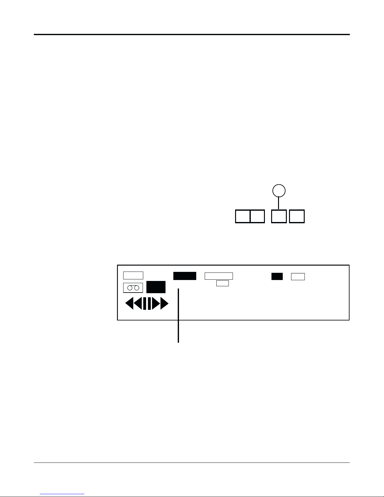
REMOVE THIS CARD AND KEEP IN A SECURE PLACE.
STOP!
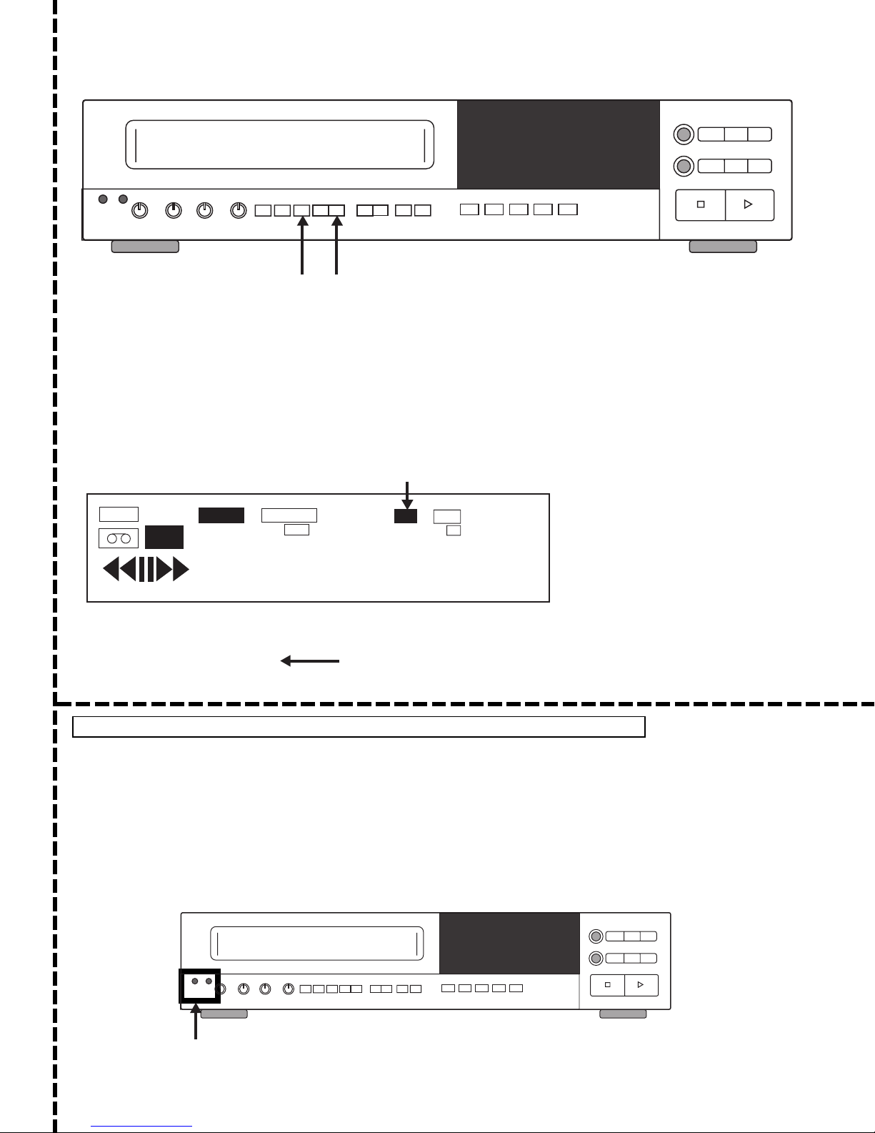
TO SET SECURITY LOCK (Locks out access to VCR functions)
Step 1. Press the NEXT and UP buttons at the same time.
Step 2. Check the digital display. The "Lock" Annunciator will light when the lock is activated. "L" will
appear below the Alarm Counter of the TIME/DATE stamp on the monitor.
Step 3. To deactivate security lock, press the NEXT and UP buttons at the same time. The "Lock"
annunciator will no longer be lit in the display. "L" will disappear from the TIME/DATE stamp
on the monitor.
THIS RECORDER HAS A CONCEALED SECURITY LOCK TO
RESTRICT UNAUTHORIZED USAGE OF THIS RECORDER.
Next
Up
NEXT & UP
BUTTONS
LOCK ANNUNCIATOR
TAB
REC
12-07-99 PL TUE A04
08:28:44A 30 T L
THE VERY FIRST TIME YOU POWER-UP YOUR VCR, PERFORM A MASTER RESET
TO PERFORM A MASTER RESET
The MASTER RESET function is performed by inserting a pointed object into each of the Reset holes at
the same time. This is used to perform a MASTER RESET for abnormal Time Lapse system operations
such as T/D DISPLAY, Speed Select, etc. All programmable features must be reprogrammed after
reset. A MASTER RESET tool is supplied with this unit.
This unit is also equipped with a SYSTEM RESET function. The SYSTEM RESET function will NOT
change any of the menu settings. See "Tape Adjustment Controls: System Reset" for further information.
Note: A SYSTEM RESET may also be performed for Mecha Lock, Cyl Lock & Reel Lock. For more
information, contact factory.
ALARM
INDEX
TAPE END
TIMER
0 0 0 0 0
LOCK
SPEED
HD
000
LOCK INDICATOR IN
TIME/DATE STAMP
End User Card
RESET
HOLES
Dealer Card
TLC2100-S16
1837-0700-4852542C


Important Safeguards
In addition to the careful attention devoted to quality standards in
the manufacture of your video product, safety is a major factor in the
design of every instrument. But safety is your responsibility, too.
These pages list important information that will help to assure
proper use of a Video Cassette Recorder and accessory
equipment. Please read it carefully before operating your video
product and keep it in a handy place for future reference.
• USE HIGH QUALITY HIGH GRADE VHS CASSETTES - This product
can be used in a mercantile bank to provide positive visual identification
of suspects by recording surveillance video camera images and time and
date information onto permanent magnetic media (video tape). The timelapse video cassette recorder and all other components of the
surveillance system must be properly installed, tested, and maintained
to fulfill this function. Carefully follow the instructions presented here and
elsewhere in the manual.
High resolution time lapse recording requires a high quality high grade
tape for satisfactory performance. Some brands of tape can have an
adverse effect on video head performance and head life. The following
brands have been found to meet our critical specifications:
GYYR BASF MAXELL TDK
• READ INSTRUCTIONS - Read all of the safety and operating
instructions before operating the equipment.
• RETAIN INSTRUCTIONS - Retain the safety and operating instructions
for future reference.
• HEED WARNINGS - Adhere to all warnings on the appliance and in the
operating instructions.
• FOLLOW INSTRUCTIONS - Adhere to all of the “operating and use”
instructions.
• GROUNDING - Do not attempt to defeat the safety purpose of the
grounding-type plug. This video product is equipped with a 3-wire
grounding- type plug (plug having a third pin for grounding.) This plug will
only fit into a grounding-type power outlet. This is a safety feature. If you
are unable to insert the plug into your outlet, contact your electrician to
replace your obsolete outlet.
• POWER SOURCES - Operate this video product only from the type of
power source indicated on the label. If you are not sure of the type of
power being used, consult your video dealer or local power company.
• OVERLOADING - Do not overload wall units and extension cords, as this
can result in a risk of fire or electric shock. Frayed power cords,
damaged or cracked wire insulation, and broken plugs are dangerous.
Periodically examine the cord and replace it if appearance indicates
damage or deteriorated insulation.
• POWER PLUG PROTECTION - Route the power-supply cords so they
cannot be walked on or pinched by items placed upon or against them.
Pay attention to cords at the plug, convenience receptacles, and the
point where the cord exits from the video product.
• VENTILATION - Do not block the slots and openings in the cabinet, or
place the video product on a bed, soft rug, or other similar surface.
These openings are provided for ventilation and to ensure reliable
operation of the video product and to protect it from overheating. This
video product should not be placed in a built-in installation such as
bookcase or rack unless proper ventilation is provided or the
manufacturer’s instructions have been followed.
• ATTACHMENTS - Do not use attachments other than those specifically
recommended by the video product manufacturer as they may cause
hazards.
Caution
Maintain electrical safety. Power operated equipment or accessories
connected to this unit should bear the UL listing mark or CSA
certification mark on the accessory itself and should not have been
modified so as to defeat the safety features. This helps avoid any
potential hazard from electric shock or fire. If in doubt, contact
qualified service personnel.
• TO PREVENT SHOCK HAZARD, DO NOT EXPOSE THIS UNIT TO
RAIN OR MOISTURE. If you spill liquid on the unit, consult authorized
service personnel. Moisture can damage internal parts. Do not use this
recorder near sources of water.
• ACCESSORIES - Do not place this video
product on an unstable cart, stand, tripod,
bracket, or table. The video product may fall,
causing serious injury to a child or adult, and
serious damage to the appliance. Use only with
a manufacturer recommended cart, stand,
tripod, bracket, or table. If mounting the video
product follow the manufacturer’s instructions
and mounting accessory.
Move an appliance and cart combination with
care. Quick stops, excessive force, and uneven surfaces may cause the
appliance and cart combination to overturn.
• CLEANING THE OUTSIDE SURFACES - Unplug this video product from
the wall outlet before cleaning. Do not use liquid or aerosol cleaners. Use
a damp cloth for cleaning.
• OBJECT AND LIQUID ENTRY - Never push objects of any kind into this
video product through openings as they may touch dangerous voltage
points or short out parts that could result in a fire or electric shock. Never
spill liquid of any kind on the video product.
• SERVICING - Do not service this video product yourself. Opening or
removing covers may expose you to dangerous voltage or other hazards.
Refer all servicing to qualified service personnel.
• CONDITIONS REQUIRING SERVICE - Unplug this video product from
the wall outlet and refer servicing to qualified service personnel under
the following conditions:
- When the power cord or plug is damaged.
- If liquid has been spilled into the video product.
- If the video product has been exposed to rain or water.
- If the video product does not operate normally after following the
instructions. Adjust only those controls that are covered by the
operating instructions. The adjustment of other controls may result in
damage and often requires extensive work by a qualified technician to
restore the video product to its normal operation.
- If the video product has been dropped or the cabinet has been
damaged.
- When the video product exhibits a distinct change in performance - this
indicates a need for service.
• REPLACEMENT PARTS - When replacement parts are required, be
sure the service technician has used replacement parts specified by the
manufacturer or have the same characteristics as the original part.
Unauthorized substitutions may result in fire, electric shock, or other
hazards and void the warranty.
• SAFETY CHECK - Upon completion of any service or repairs to this
video product, ask the service technician to perform safety checks to
determine that the video product is in safe operating condition.
• IMPORTANT NOTE TO THE INSTALLER - This installation should be
made by a qualified service person and should conform to all local
codes.
In order to provide this product with protection against risk of
unintentional operation by employees, customers, janitors and cleaners
working on the premises, and from falling objects, building vibrations and
similar causes, it is recommended:
- This product be enclosed in a tamper-resistant lock box. Make sure
that the lock box is well ventilated or maintained with an air cooling
system.
- That security locking procedures described on the detachable card at
the front of this manual be followed.
1837-0700-4852542C


TABLE OF CONTENTS
GETTING STARTED
Introduction ............................................................................................................................ 1
CONTROLS
Introduction .............................................................................................................................2
Front Panel Controls ............................................................................................................... 3
Cassette Compartment and Eject Button ......................................................................... 3
Tape and Picture Adjustment Controls .............................................................................3
Play/Record Operation Controls .......................................................................................4
Programming Operation Controls .....................................................................................5
Position and Alarm Controls .............................................................................................5
Timer and Miscellaneous Controls ...................................................................................6
Digital Display .........................................................................................................................7
Rear Panel Functions .............................................................................................................9
Installation .............................................................................................................................11
Video and 15-Pin Connector Installation ........................................................................11
Audio Installation............................................................................................................. 12
Record Check Function ........................................................................................................13
Alarm Index Operation .......................................................................................................... 14
MENUS
Menu Tree .............................................................................................................................15
To Move and Edit in the Menus ......................................................................................16
Main Menu ............................................................................................................................17
Time/Date Submenu .......................................................................................................17
Example of Setting the Clock and Navigating a Menu .............................................18
Display Options Submenu ..............................................................................................19
System Code............................................................................................................. 19
Record Display Options Submenu............................................................................20
Record Text Positions Submenu ...............................................................................21
Spot Display Options Submenu ................................................................................22
Spot Text Positions Submenu ...................................................................................22
Tape Search/Management Submenu .............................................................................23
Time/Date Search Submenu ....................................................................................24
Transaction Search Submenu ...................................................................................24
T/D and Trans. Search Submenu ..............................................................................25
Encoding Options Submenu .....................................................................................25
Tape Management Overview ....................................................................................26
Tape Management Submenu..............................................................................27
TMS Interaction with Other VCR Features..........................................................29
System Options Submenu ..............................................................................................30
7-Day Timer Program Submenu ..................................................................................... 31
Copy/Repeat All Days Submenu ..............................................................................32
TLC2100-S16
1837-0700-4852542C
i

Alarms Submenu ............................................................................................................33
Alarm Memory Submenu ..........................................................................................33
Alarm Memory Browse Submenu .............................................................................34
Alarm Inputs Submenu .............................................................................................34
Alarm Sequencing Submenu ....................................................................................35
Day (Night) Alarm Function Submenu ................................................................ 36
Day (Night) Alarm Sequence Submenu........................................................38
Day (Night) Alarm Sequence Submenu (Homed Cameras) .........................39
Day (Night) Alarm Priority Submenu ...................................................................40
Alarm Record Options Submenu ........................................................................40
Switcher Programming Submenu ...................................................................................41
Timer Mode Submenu ..............................................................................................41
Day (Night) Rec Sequence Submenu.......................................................................42
Day (Night) Spot Sequence Submenu .....................................................................42
Camera Titles Submenu ...........................................................................................43
Camera Phasing Submenu.......................................................................................44
RS-232 Submenu ...........................................................................................................45
MP Port Submenu .....................................................................................................45
Configure Serial Submenu..................................................................................45
Address Select Submenu ...................................................................................46
Sync to ATM Time Submenu...............................................................................47
ATM Text Formatter Submenu .............................................................................48
Standard Formatter Submenu ......................................................................48
Custom Formatter Submenu .........................................................................50
MultiLink/Remote Port Submenu ..............................................................................52
Remote Terminal Interface Commands...............................................................52
System Data Submenu ...................................................................................................60
APPENDICES
Appendix A: External Interface: 15-Pin “D” Connector Pinout ..............................................61
Appendix B: Remote Control Feature...................................................................................63
Appendix C: Warning Codes .................................................................................................64
Appendix D: Periodic Maintenance.......................................................................................66
Appendix E: Troubleshooting ................................................................................................67
Appendix F: Specifications ...................................................................................................69
ii
TLC2100-S16
1837-0700-4852542C
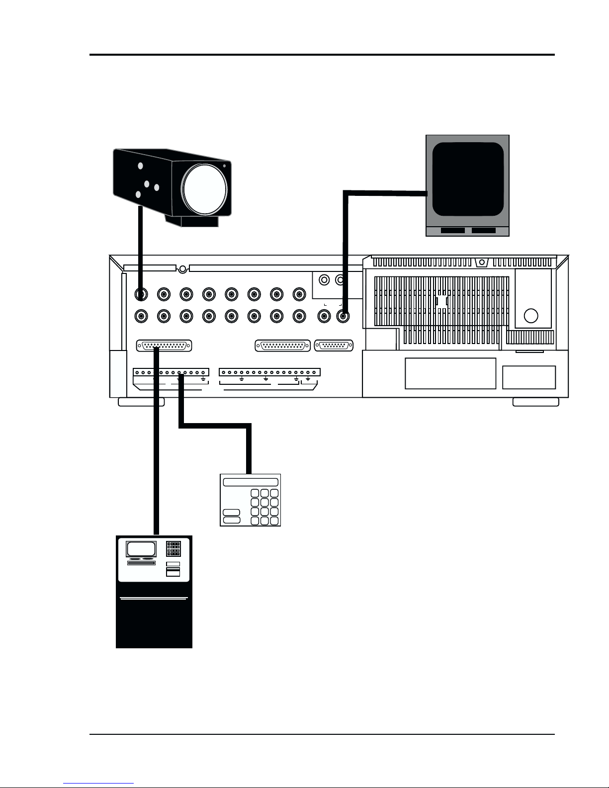
Typical Security System
with ATM
This diagram depicts a typical installation at a security system site.
For detailed installation and rear panel interface information, see
the "Rear Panel Functions"and "Installation" sections of this
document.
Video In
Video Camera
12345
910111213
MP PORT RS-232 REMOTE
IN IN
ALARMS
6
14
Alarm Port
Video Out
78
15 16
SPOT
OUT
EXTERNAL FUNCTIONS
12
IN OUT
AUDIO
5V
Monitor
VCR
OUT
EZ Bank ATM
Automated
Teller Machine
TLC2100-S16
1837-0700-4852542C
Alarm Panel
iii

iv
TLC2100-S16
1837-0700-4852542C

GETTING STGETTING ST
GETTING ST
GETTING STGETTING ST
ARAR
AR
ARAR
TEDTED
TED
TEDTED
INTRODUCTION
If you have never used a time-lapse recorder system before, this section will explain
what you need to do to get started.
Besides your time-lapse recorder, you will need the following equipment:
• a video camera
• analog monitor (VCR Out) and a spot monitor
• cables for the camera and monitor (typically these are coax cables with BNC connectors)
• a T-120 or T-130 VHS video tape. We recommend Gyyr, BASF, Maxell, and TDK
tapes.
• power sources for the VCR, camera, and monitor
Before connecting any piece of equipment to a power source, make the following
connections:
• connect cameras to the VCR's Video In connectors
• connect the analog monitor to the VCR's Video Out connector
• connect the Spot monitor to the Spot Out connector
• plug in all of your equipment to their power sources. This VCR unit connects into a
120 VAC wall outlet
• The very first time you power-up your VCR, perform a Master Reset. The procedure
for performing a Master Reset is on the detachable “Stop” page at the beginning of
this manual.
• insert a video tape into the unit
Your monitor should now display your camera's image. You will also see a Time/Date
display on the monitor with its factory default setting. A message will be displayed at
the bottom of the monitor screen: “Set Clock“.
If you wish to program the Time/Date Display, see “Time/Date Submenu” section of
this manual. A step-by-step description is covered in that section.
You will also notice that the letters “PL” are flashing in the Time/Date display. “PL”
stands for Power Loss. To remove “PL” from the display, simply press the Alarm Reset
button. However, be aware as you learn about the more advanced functions of your
VCR, that pressing the Alarm Reset button when “PL” is not blinking, will also clear the
alarm memory.
If you wish to display the VCR's On-Screen Menus, press the Prog. button. Information
about all the Programming Buttons is found in the “Front Panel Controls” section of this
manual. Information about the VCR's On-Screen Menus is found in the “Menus” section
of this manual.
If you wish to learn more about the Front Panel Controls, you might begin with the Play/
Record Operation Controls. Information about these controls is found in the “Front
Panel Controls” section of this manual. These controls are somewhat similar in operation to those of a home VCR.
As you are operating your recorder, keep an eye on the Digital Display and become
familiar with the various indicators. This display will become invaluable as you become
more comfortable with the operation of your recorder.
To learn more about the Tape Search and Management features, refer to the “Tape
Search and Management” section.
TLC2100-S16
1837-0700-4852542C
1
CONTROLS
INTRODUCTION
S
SHARPNESS 2-A24HR
Tape and Picture
Adjustment Controls
TRACKING
SLOW
TRACKING
VLOCK
Compartment
Digital Display
PREV. DOWN
PROG. NEXT UP
V-POS H-POS ALARM
INDEX
ALARM
RESET
COUNTER
RESET
REC / PLAY
HOURS
TIMER DAYLIGHT
ABC
SAVINGS
Programming and Timer
Operations Controls
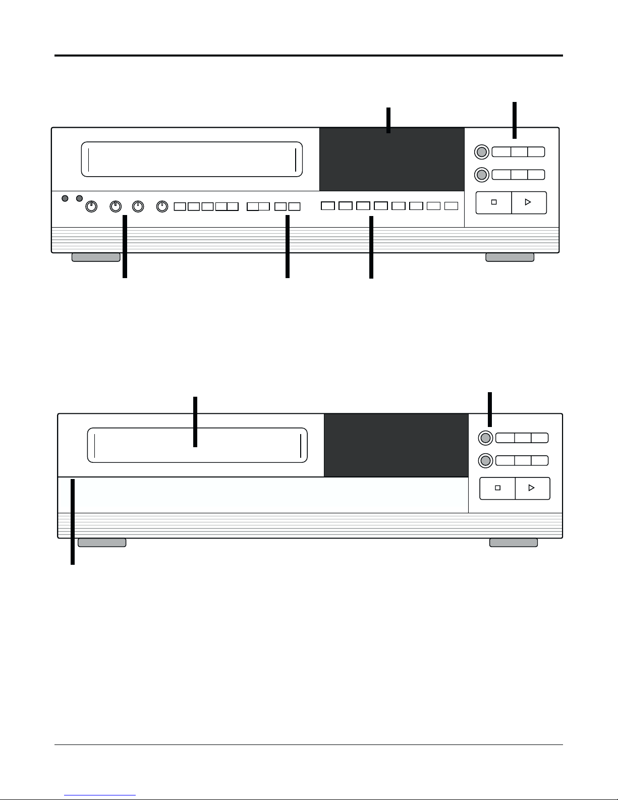
Front Panel with Control Compartment Open
Cassette
Record / Play
Operations
Controls
FIELD
EJECT
REC
STILL FIELD
REV
REVERSE
REW/
PLAY
SEARCH
STOP PLAY
FWD
F. FWD/
SEARCH
Tape
Eject
Button
S
SHARPNESS 2-A24HR
TRACKING
SLOW
TRACKING
Gently pull forward
here to open panel
PREV. DOWN
PROG. NEXT UP
VLOCK
V-POS H-POS ALARM
INDEX
ALARM
RESET
COUNTER
RESET
REC / PLAY
HOURS
TIMER DAYLIGHT
ABC
SAVINGS
Front Panel with Control Compartment Closed
FIELD
EJECT
REVERSE
REC
STOP PLAY
REV
PLAY
STILL FIELD
REW/
SEARCH
FWD
F. F WD /
SEARCH
2
TLC2100-S16
1837-0700-4852542C
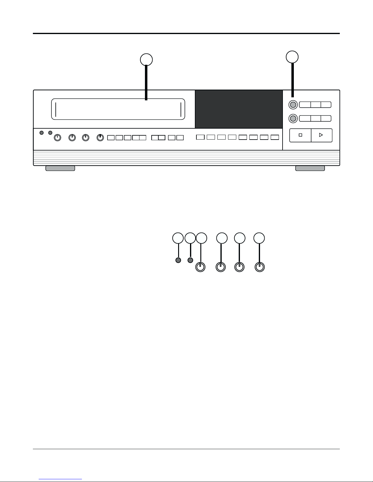
FRONT PANEL CONTROLS
Cassette
Compartment and
Eject Button
S
SHARPNESS 2-A24HR
TRACKING
SLOW
TRACKING
VLOCK
PREV. DOWN
PROG. NEXT UP
1
V-POS H-POS ALARM
INDEX
ALARM
RESET
COUNTER
RESET
REC / PLAY
HOURS
TIMER DAYLIGHT
SAVINGS
ABC
2
FIELD
EJECT
REVERSE
REC
STOP PLAY
REV
PLAY
STILL FIELD
REW/
SEARCH
SEARCH
FWD
F. FWD/
Tape and Picture
Adjustment
Controls
1 FRONT PANEL LOADING CASSETTE COMPARTMENT
Insert either a S-VHS video tape cassette or VHS video tape cassette into this
compartment. This unit can automatically detect which type of tape is inserted.
2 TAPE EJECT BUTTON
Press to remove the cassette. The Eject Button will not operate in the RECORD
mode.
4 5
3
S
6
SHARPNESS 2-A24HR
TRACKING
7
SLOW
TRACKING
8
VLOCK
3 SEE “STOP” INSERT CARD AT FRONT OF THE MANUAL
4 SYSTEM RESET
Insert a reset tool into this hole (marked “S“) to reset unit without changing menu
settings. This function will reset the unit for warning errors (see Appendix C:
Warning Codes“).
5 SHARPNESS
Use this control to adjust picture sharpness during playback.
6 2-A24 HOUR TRACKING/6-A30 HOUR TRACKING
7 SLOW TRACKING
8 V-LOCK
TLC2100-S16
1837-0700-4852542C
Adjust to optimize the picture quality during playback speeds of 2 to A24 hours
for normal play and 6 to A30 hours in the High-Density (HD) mode.
Adjust to optimize the picture quality during slow playback speeds, that is, speeds
of 24 hours and over for normal play and speeds of 30 hours and over in the HD
mode.
Adjust this control to reduce vertical jitter in the STILL mode.
3
Play/Record
Operations
Controls
Follow this procedure for the
best results when reviewing a
time-lapse recorded tape:
1. With the VCR in PLAY (#16),
and without a particular event
in mind, place the VCR in the
2-hour speed. This is the
fastest playback speed and
can usually be used quickly to
locate an event.
2. Once an event has been
identified, slow the unit to 24hour, 48-hour or any other
slower speed. These slower
speeds will allow close
examination of the situation
and ample time to react.
3. Select the STILL (#10) mode
to stop the tape. Use FIELD
FWD (#11) or FIELD REV (#9)
to get the exact field you wish
to review.
10
119
FIELD
EJECT
REC
REV
REVERSE
PLAY
12
STILL FIELD
FWD
REW/
F. FWD/
SEARCH
SEARCH
13 14
9 FIELD REVERSE
Press to reverse the tape by one field in the STILL playback mode.
10 STILL
Press to temporarily stop tape motion in the PLAY mode.
11 FIELD FORWARD
Press to advance the tape one field in the STILL playback mode.
12 REVERSE PLAY
Press to play recorded material at 02, 72, 120, 180, 240, 360, 480, 600, 720, or 960
hours during the PLAY mode.
13 REWIND/SEARCH
Press to rewind. If pressed during PLAY mode, the recorder will perform a high
speed reverse playback (search). Search speeds are variable and selectable. See the
“System Options: Search Speed” section of this manual for more information.
14 FAST FORWARD/SEARCH
Press to activate fast forward. If pressed during PLAY mode, the recorder will
perform a high speed forward playback (search). Search speeds are variable and
selectable. See “System Options: Search Speed” section of this manual for more
information.
15 STOP
Press to stop the tape. This button must be pressed to end the RECORD mode.
REC
17
16 PLAY
17 RECORD
4
STOP PLAY
15
16
Press to play recorded material. PLAY speeds are 02, A18, A24, 24, 48, 72, 120, 180,
240, 360, 480, 600, 720, and 960 hours. The Play button is also used for the Record
Check function. See the “Record Check” section of this manual for more information.
Press to start recording. RECORD speeds are 02, 18, 24, 48, 72, 120, 180, 240, 360,
480, 600, 720, and 960 hours.
TLC2100-S16
1837-0700-4852542C
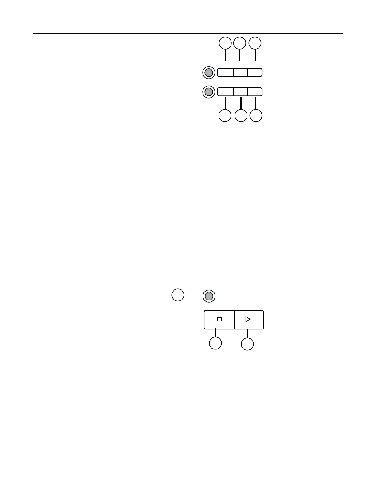
Programming
Operation
Controls
18 19 20
PREV. DOWNPROG. NEXT UP
18 PROG. (PROGRAM) BUTTON
Press to display Main Menu. Also used for various Menu functions. See “To Move
and Edit in the Menus” for more information about all the programming control
buttons.
19 PREV. (PREVIOUS) BUTTON
Press to go back to the previous position.
20 NEXT BUTTON
Press to go to the next position.
21 DOWN BUTTON
Press to change to a lower value or to move to next line in a menu.
22 UP BUTTON
Press to change to a higher value or to move to the previous line in a menu.
21 22
Position and
Alarm Controls
23 24
V-POS H-POS ALARM
23 V-POS (VERTICAL POSITION) BUTTON
Press repeatedly to control the vertical position of the Time/Date display. Moves
display through 7 positions of the monitor screen. This function works only with
the Spot monitor in most modes; however, when in the Preview mode, it operates
only with the VCR output.
24 H-POS (HORIZONTAL POSITION) BUTTON
Press repeatedly to control the horizontal position of the Time/Date display. As
with the V-POS buttons, this function works only with the Spot monitor in most
modes; however, when in the Preview mode, it operates only with the VCR output.
25 ALARM SEARCH INDEX BUTTON
Press to activate Alarm Search Index function. See “Alarm Index” section of this
manual for more information.
26 ALARM RESET BUTTON
Press to clear all ALARM and POWER LOSS information.
Press once to clear “PL” in the Time/Date stamp (if this condition exists).
Press twice (press only once if there is no Power Loss) to clear the Alarm Memory
List.
INDEX
25
26
ALARM
RESET
TLC2100-S16
1837-0700-4852542C
5

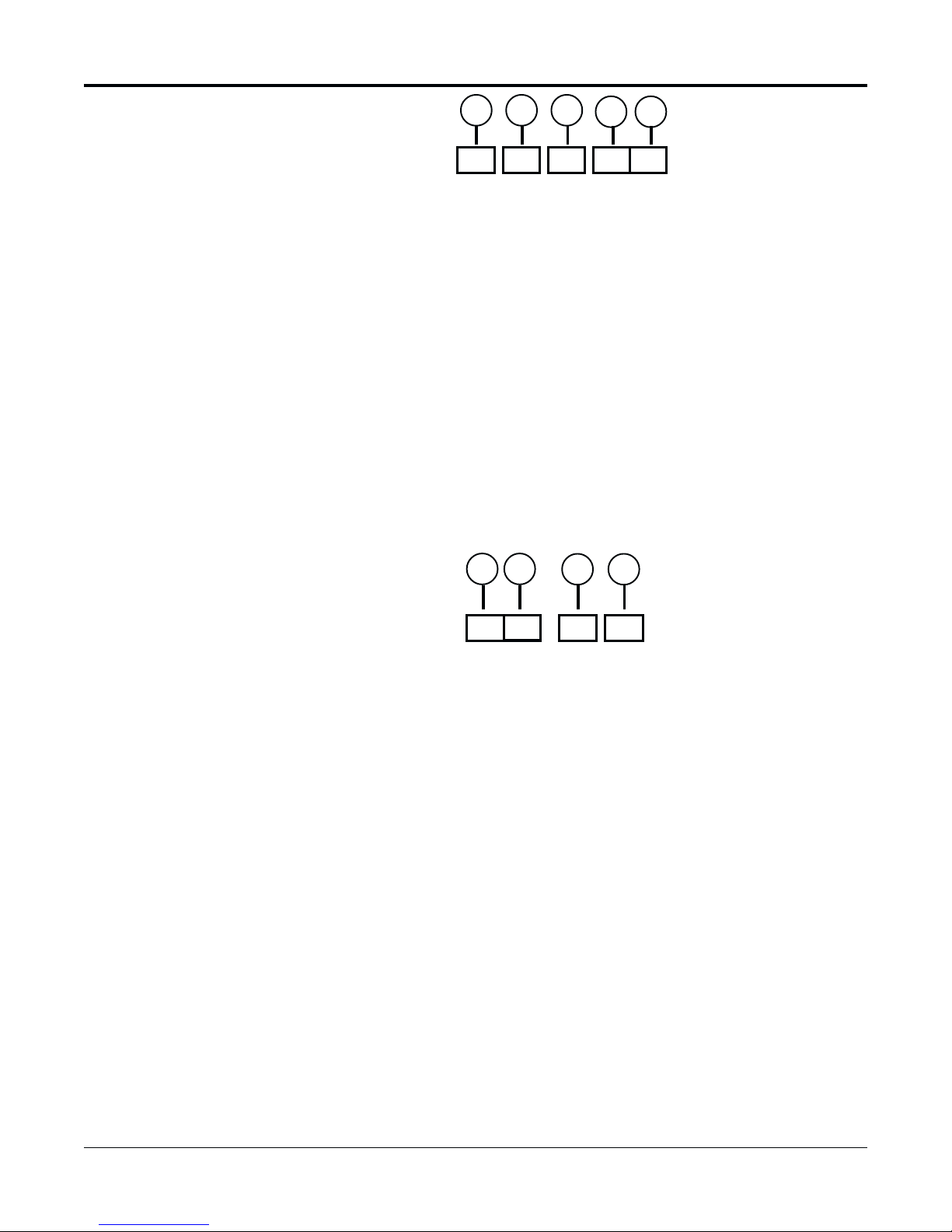
Timer and
Miscellaneous
Controls
28 30
27 29
31
32
33
COUNTER
RESET
REC / PLAY
HOURS
TIMER DAYLIGHT
SAVINGS
ABC
27 COUNTER RESET
Press to set the digital counter to “0000“. See the “Digital Display” section of this
manual for more information.
28 REC / PLAY HOURS (DOWN)
Press Down to change the Play or Record speed to a lower value.
29 REC / PLAY HOURS (UP)
Press Up to change the Play or Record speed to a higher value.
30 TIMER BUTTON
Press after programming the TIMER for automatic TIMER recording. The Timer
annunciator will light and a “T” will be displayed in the Time/Date Stamp on the
monitor. See the “Timer Indicator” section of this manual for more information.
31 DAYLIGHT SAVINGS
Press and hold this button, then UP (#22) or DOWN (#21) to change hours in Time/
Date display. Simplifies Daylight Savings Time changes. Each time UP or DOWN
is pressed, the Hour digit will change by one hour.
32 A - MANUAL/AUTO BUTTON
Toggles between Manual and Auto modes of the Spot Out. In Manual mode, press
UP or DOWN to manually page through cameras; pressing DOWN selects the
previous camera and pressing UP selects the succeeding camera. If Auto mode is
selected, the unit will automatically switch cameras, that is, sequence through the
selected cameras for selected periods of times, called dwells. This function may
also be set with the on-screen menus. See the “Spot Mode” section of this manual
for more information.
33 B, C
6
Spares, not currently in use.
TLC2100-S16
1837-0700-4852542C
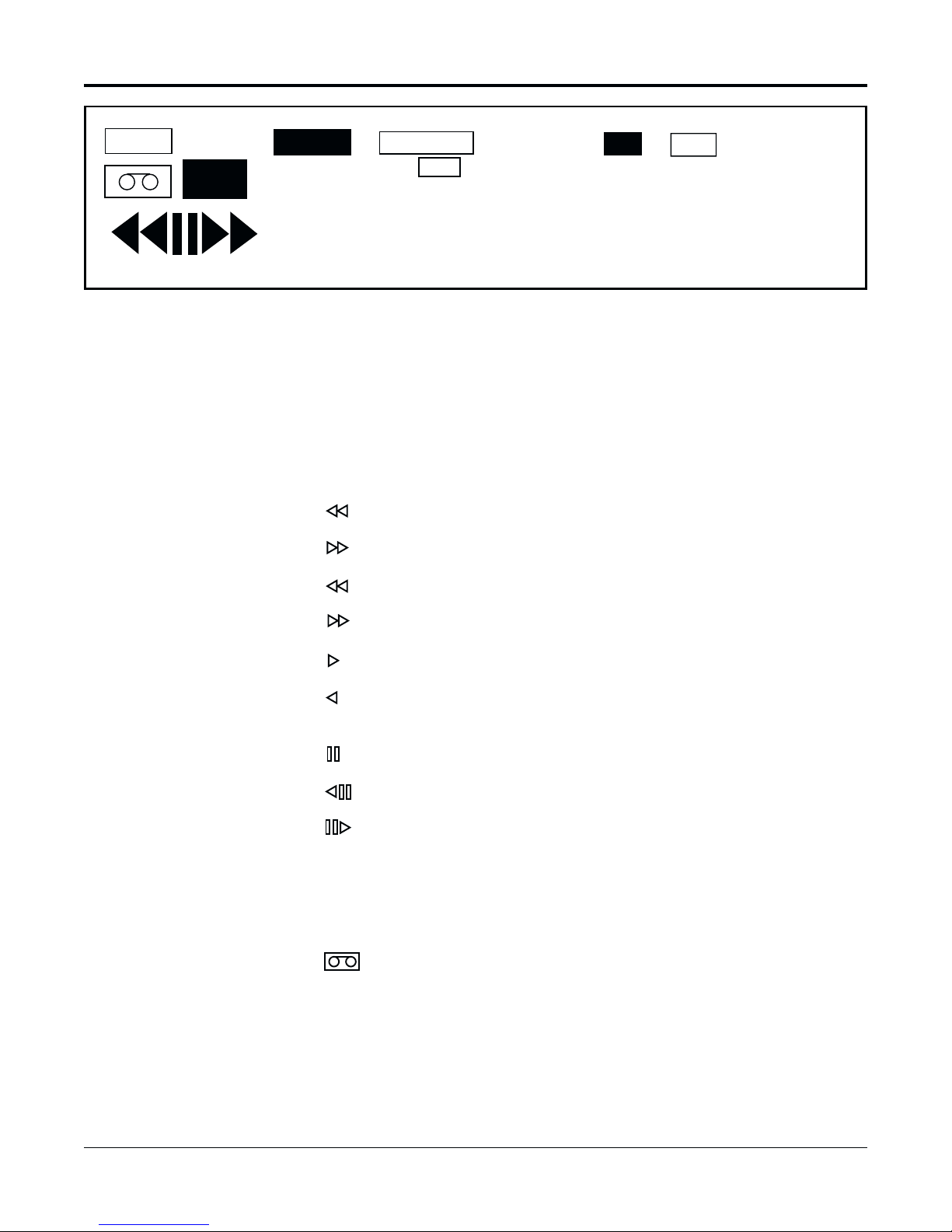
DIGITAL DISPLAY
TAB
REC
ALARM
INDEX
TAPE END
TIMER
B
0 0 0 0
34 DIGITAL DISPLAY
The Digital Display annunciates the following features
MODE INDICATORS:
REC Lights during RECORD mode.
Lights during REWIND mode.
Lights during FAST FORWARD mode.
Flashes during REW SEARCH mode.
LOCK
SPEED
R
0 0 0
Note: The STILL mode is restored when the FIELD
REVERSE or FIELD ADVANCE button is released.
Note: The unit can remain in
STILL mode for 5 minutes. After
5 minutes, the unit will
automatically enter STOP
mode.
Flashes during F. FWD SEARCH mode.
Lights during PLAY mode.
Lights during the REVERSE PLAY mode. Automatically cancels after 1
minute.
Lights during STILL mode.
Lights while the FIELD REVERSE is depressed in STILL mode.
Lights while the FIELD ADVANCE is depressed in the STILL mode.
TAB Lights when a cassette without a safety tab is loaded. If tab indicator is
illuminated, the recorder cannot be placed in RECORD mode.
ALARM Lights during alarm recording. Indicator flashes when alarm ends.
(TAPE-IN) Lights when a video cassette is loaded in the Cassette
Compartment.
INDEX Lights when the Alarm Index button is pressed and the Index Mode is
on. See “Alarm Index Operation” and “Alarm Index Button #25“.
TLC2100-S16
1837-0700-4852542C
7

TAPE END
Lights when the end of the tape is reached during RECORD mode. When TAPE
END indicator is lit, the tape must be ejected in order to turn off the TAPE END
indicator in the display. Tape must be ejected and reinserted before the Record
function will operate.
Will NOT light when RE-REC, EVEN IF ALARM has been selected in the “ALARM
RECORD OPTIONS” menu. See the “Alarm Record Options Submenu” section of
this manual for more information.
OR
Will NOT light if an alarm recording has not been made and RECYCLE, STOP IF
ALARM was selected from the “ALARM RECORD OPTIONS” menu.
TIMER INDICATOR
Lights during Timer recording and also when unit is in STOP mode.
Flashes when Timer mode is entered and one or more of the following conditions
exists:
• A cassette is not loaded.
• A cassette without a safety tab is loaded.
• The Timer has not been programmed.
LOCK INDICATOR
Lights when the recorder is in the Security Lock mode. All front panel controls are
disabled when lock indicator is lit.
B, R
B or R will light when the Brown (+azimuth) head or Red (-azimuth) head mode
is selected in the System Options submenu.
DIGITAL COUNTER (0000)
Shows the tape time counter. Each digit incremented represents 1 second of time
in 2-hour speed. If the counter is reset to 0000 at beginning of tape, a T120 cassette
will increment the counter to approximately 7200 at end of tape. In modes other
than RECORD, the counter will increment or decrement only where a recording
was made, i.e., when going over a section of blank tape, the counter will not
change.
TAPE SPEED INDICATOR (000), SPEED ANNUNCIATOR
Displays the selected Tape Speed. The Speed annunciator will light in conjunction
with the Tape Speed Indicator.
8
TLC2100-S16
1837-0700-4852542C
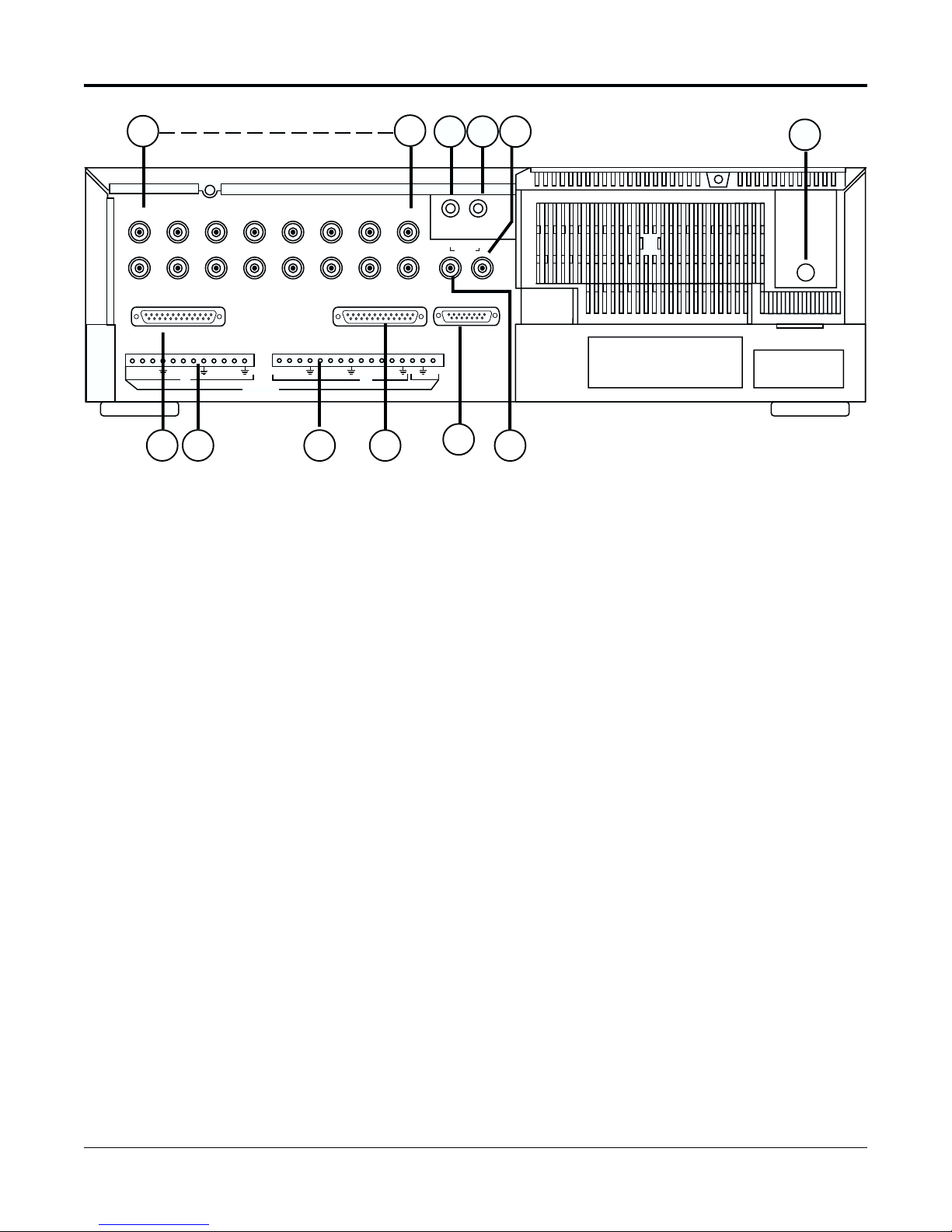
REAR PANEL FUNCTIONS
35
12345
910111213
MP PORT RS-232 REMOTE
IN IN
ALARMS
4140 4342
Note: Text displays for the two
monitors can be programmed
independently. See the “Display Options” section for more
information.
35
36 37 38
78
6
IN OUT
15 16
14
AUDIO
SPOT
OUT
EXTERNAL FUNCTIONS
12
5V
44
VCR
OUT
45
35 VIDEO IN
Receives composite video signals from up to 16 video cameras or other VCRs.
36 AUDIO IN
Accepts line level audio signal from external sound equipment or another recorder.
37 AUDIO OUT
Provides a line level audio output for a monitor or another recorder.
39
38 VCR OUT
For connection to a monitor; menus will be displayed on this monitor.
39 POWER CORD (not shown)
Connect to 120 VAC power supply (normally a typical wall socket).
40 25-PIN MULTI PROTOCOL PORT
Connect to ATMs. The following pins are supported:
1. GND 7. GND
2. TX/RX 15. RCLK (IN)
3. RX/TX 17. TCLK (IN)
4. RTS/CTS 20. DTR (IN)
5. CTS/RTS
TLC2100-S16
1837-0700-4852542C
9

41, 42 ALARMS IN (18 inputs) and OUT (2 out, plus GND)
On-screen programming of inputs as normally open or normally closed.
First Alarm Port:
1. Alarm 1 7. Alarm 6
2. Alarm 2 8. GND
3. Alarm 3 9. Alarm 7
4. GND 10. Alarm 8
5. Alarm 4 11. Alarm 9
6. Alarm 5 12. GND
Second Alarm Port
13. Alarm 10 21. Alarm 16
14. Alarm 11 22. Alarm 17
15. Alarm 12 23. Alarm 18
16. GND 24. GND
17. Alarm 13 25. Alarm Out 1
18. Alarm 14 26. GND
19. Alarm 15 27. Alarm Out 2
20. GND 28 +5V
43 REMOTE PORT (25-PIN) CONNECTOR
Interface with PCs or other controlling devices. See the “RS-232/Multiprotocol
Features” section of this manual for more information. The supported pins are as
follows:
1. GND 4. CTS
2. RX 5. RTS
3. TX 7. GND
44 EXTERNAL INTERFACE (15-PIN) JACK
Connect an alarm switch, door sensor, etc. using the 15-pin adapter provided.
1. ALARM IN 8. REC CHECK IN
2. ALARM OUT 9. TIMER OUTPUT
3. NC 10. REC START IN
4. REC OUT 11. TAPE END OUT
5. 12 VDC, FUSED 12. NC
6. WARNING OUT 13. REMOTE IN
7. LOW TAPE OUT 14-15. COMMON
See the “APPENDIX A, EXTERNAL INTERFACE” section of this manual for a
detailed description of the 15-Pin Connector PINOUT.
45 SPOT OUT
Monitor connection to view live camera channels. Note: menus cannot be displayed on this monitor. However, this monitor may be programmed to display its
own Time/Date stamp and text. See the “Spot Display Options Submenu” section
of this manual for more information. Text displayed on this monitor is programmed independently from the VCR Out monitor.
10
TLC2100-S16
1837-0700-4852542C
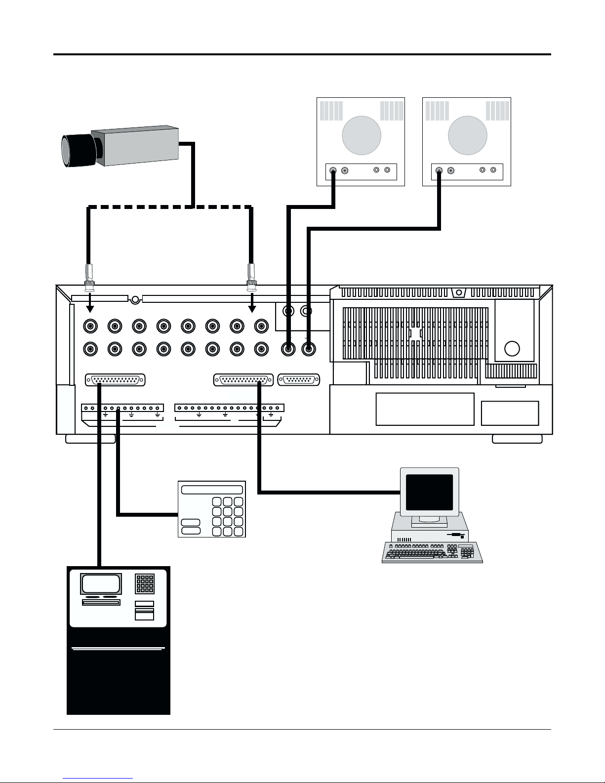
INSTALLATION
Video and 15-pin
Connector
Installation
Video
Camera
Connect up to 16 Video Cameras
Video
In
Spot
Monitor
Video
In
VCR Out
Monitor
12345
910111213
MP PORT RS-232 REMOTE
IN IN
ALARMS
6
14
Connect to
Alarm Switch,
Alarm Panel,
Door Sensor,
etc.
Alarm Panel
AT M
Video
Out
78
15 16
SPOT
OUT
12
IN OUT
AUDIO
EXTERNAL FUNCTIONS
5V
Video
Out
VCR
OUT
PC
Connect to
ATMs, ECRs,
Scales, etc.
EZ Bank ATM
TLC2100-S16
1837-0700-4852542C
11
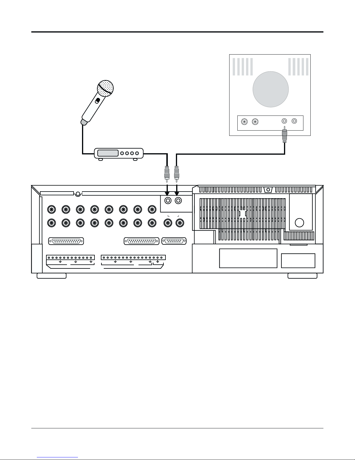
Audio Installation
Microphone
Monitor
Audio
In
Preamp
12345
910111213
MP PORT RS-232 REMOTE
IN IN
ALARMS
14
A microphone, connected to a pre-amp, may be interfaced with this unit. For best
results, audio recording is recommended at 02 hour speed. However, audio may be
recorded at 18- or 24-hour speeds. Installation diagram is shown above.
To record audio, choose audio recording speed with RECORD HOURS (#28 or #29)
button(s). Then press REC (#17) button. Press STOP to end recording.
6
Audio
In
78
15 16
SPOT
OUT
12
Audio
Out
IN OUT
AUDIO
EXTERNAL FUNCTIONS
5V
VCR
OUT
To playback audio recording, first choose appropriate tape speed: 02, A18, A24 with
the PLAY/RECORD HOURS button(s). Then press PLAY (#16) button.
12
TLC2100-S16
1837-0700-4852542C
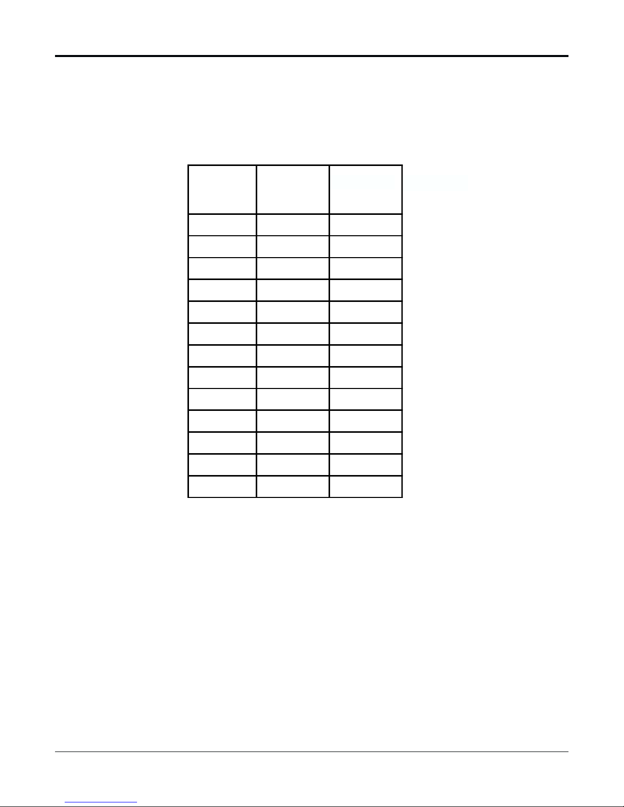
RECORD CHECK FUNCTION
Introduction
Note: This function will not
operate when the Security
Lock is functioning.
The Record button also has a Record Check function associated with it. If the PLAY
button is pressed when the unit is in RECORD mode, several seconds of recorded
material will be displayed on the monitor so that the recording quality can be checked.
The Table below shows the relationship between Record/Playback speeds and the tape
rate (pictures/second) for applications where the record rate is required.
REC Time
(Hou rs)
Norm
Mode
Fields/Sec
Norm
Mode
Sec/Fields
2600.016
18 6.66 0.15
24 5.0 0.2
48 2.5 0.4
72 1.66 0.60
120 1.0 1.0
180 0.666 1.5
240 0.5 2.0
360 0.33 3.0
480 0.25 4.0
600 0.2 5.0
720 0.166 6.0
960 0.125 8.0
TLC2100-S16
1837-0700-4852542C
13
ALARM INDEX OPERATION
V-POS H-POS ALARM
INDEX
ALARM
RESET
Introduction
Note: The Alarm Index search
operates with recordings made
at the 2-, 18-, and 24-hour
speeds in normal mode. We
recommend that at least one
minute of an alarm be recorded
with the 18-, 24- and 30-hour
speeds.
The Alarm Index allows the user to search the video tape for the next occurrence
of an alarm on the tape.
To activate Alarm Index:
1. Press the Alarm Index button (button #25, see diagram below). The INDEX
annunciator on the VCR’s display will light.
2. Press PLAY, then F.FWD/SEARCH (or REW/SEARCH). The unit will
perform a fast forward search (or reverse search) until the next occurrence
of an alarm is found. The unit will then automatically enter the PLAY mode
at whatever playback speed has been previously selected.
3. To search for the next alarm occurrence, simply press F.FWD/SEARCH (or
REW/SEARCH).
Note: If too few fields of an alarm have been recorded, the unit may overshoot the
alarm recording. However, the unit will still drop into the PLAY mode when it
recognizes the alarm.
25
TAB
REC
Index Annunciator
ALARM
INDEX
TAPE END
TIMER
0 0 0 0
LOCK
B
SPEED
R
0 0 0
14
TLC2100-S16
1837-0700-4852542C
MENUS
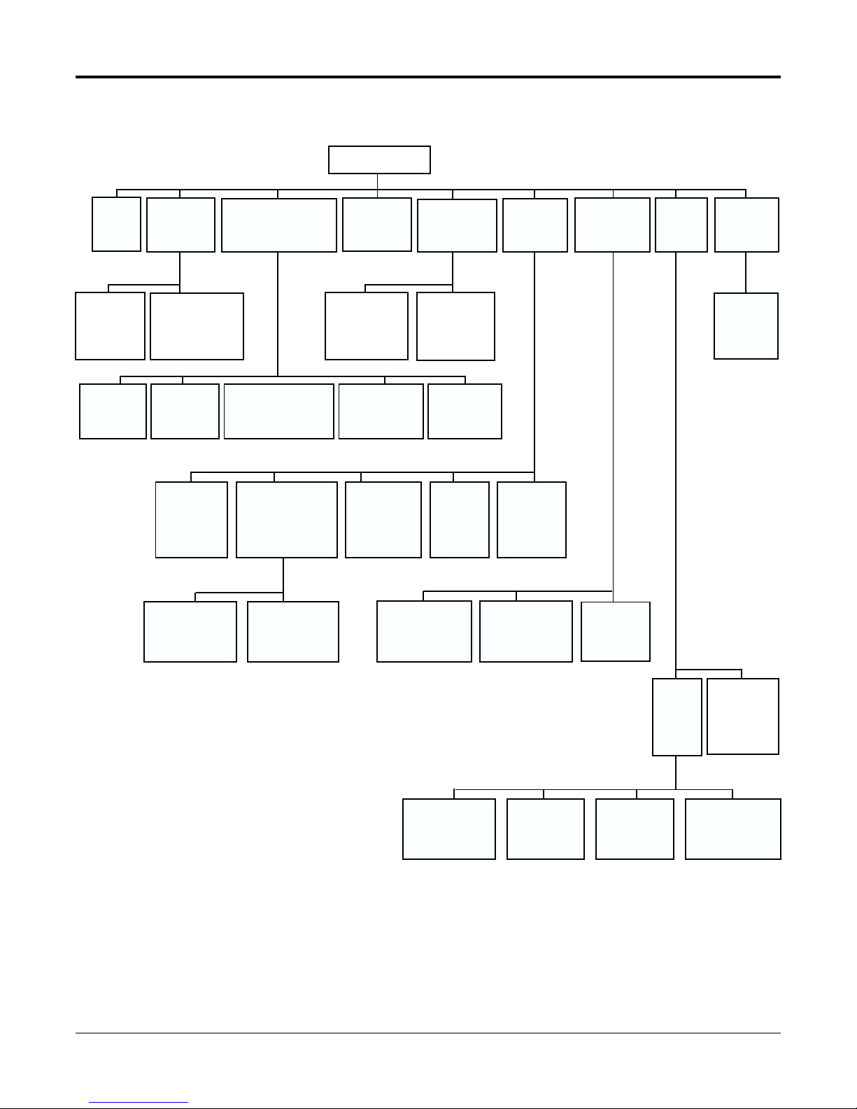
MENU TREE
MAIN MENU
TIME/
DATE
RECORD
[SPOT]
DISPLAY
OPTIONS
TIME/
DATE
SEARCH
DISPLAY
OPTIONS
RECORD
[SPOT] TEXT
POSITIONS
TRANSACTION
SEARCH
ALARM
MEMORY
DAY [NIGHT]
SEQUENCE
TAPE SEARCH /
MANAGEMENT
T/D and
TRANSACTION
SEARCH
ALARM
SEQUENCING
DAY [NIGHT]
ALARM
PRIORITY
SYSTEM
OPTIONS
DAY OF
THE WEEK
TIMERS
ENCODING
OPTIONS
ALARM
MEMORY
BROWSE
DAY [NIGHT]
RECORD
SEQUENCE
7-DAY
TIMER
PROGRAM
COPY /
REPEAT
ALL DAYS
TAPE
MANAGEMENT
ALARM
INPUTS
ALARMS
ALARM
RECORD
OPTIONS
DAY [NIGHT]
SPOT
SEQUENCE
SWITCHER
PROGRAMMING
CAMERA
TITLES
RS232
SYSTEM
DATA
ABOUT
TLC2100-S16
1837-0700-4852542C
CONFIGURE
SERIAL
ADDRESS
SELECT
SYNC TO
ATM TIME
MP
PORT
ATM
TEXT
FORMATTER
MULTILINK/
REMOTE
PORT
15

To Move and Edit
in the Menus
To Move and Edit in the menus:
• Press PROG. (#18) to display Main Menu.
• Press DOWN (#21) or UP (#22) to move the cursor from one menu line to another.
Example in moving the cursor:
• If you wish to move the cursor from the “Exit” line to the “System Options” line on
the Main Menu window, press DOWN four times or UP six times. See the “Main
Menu” section of this manual for more information.
• When the cursor is at the last line of the menu, if DOWN is pressed, the cursor will
move to the first line of the menu. Similarly, if the cursor is at the first line of the menu
and UP is pressed, the cursor will move to the last line of the menu.
• When the cursor is at a line you wish to edit, press PROG. to begin editing.
• To change a value in a line, highlight value and then press DOWN or UP.
• If there is more than one parameter to edit in a line, press PREV. (Previous #19) or
NEXT (#20) to move from one parameter to the next.
Example in editing:
• You may wish to edit “Date” in the Time/Date submenu. “Date” has three parameters:
month, day, year (for this example, we will assume that the format mm/dd/yy has
been selected). Press PROG. to begin editing. The first parameter, month, will be
highlighted. Use DOWN or UP to choose the desired value for the month. Then press
NEXT to begin editing the Day parameter. Press NEXT when you wish to edit the
Year value. If you wish to change values you have already entered, press PREV. to
return to the Day parameter or press PREV. twice to return to the month parameter.
• Press PROG. or NEXT when you're finished editing a line.
• If a line has a “>” at the rightmost position, the line has a submenu. When you press
PROG. when the cursor is at a line with a “>“, the submenu will be displayed.
A detailed example of programming a menu will be presented in the Time/Date
submenu.
16
TLC2100-S16
1837-0700-4852542C
 Loading...