

Gyyr TLC 2100 Operating Instructions Manual

TLC 2100 TIME LAPSE
VIDEO RECORDER
RS232 OPTIONAL FEATURE
DC OPTIONAL FEATURE
OPERATING INSTRUCTIONS
TM

WARNING: TO PREVENT FIRE OR ELECTRIC SHOCK, DO NOT
EXPOSE THIS APPLIANCE TO RAIN OR MOISTURE.
CAUTION
RISK OF ELECTRICAL SHOCK
DO NOT OPEN!
CAUTION! TO PREVENT ELECTRIC SHOCK DO NOT REMOVE
COVER. NO USER SERVICEABLE COMPONENTS INSIDE. REFER
SERVICING TO QUALIFIED SERVICE PERSONNEL.
The lightning flash with the
arrowhead symbol, within
an equilateral triangle, is
intended to alert the user
to the presence of uninsulated "dangerous voltage" within the product's enclosure that may be of sufficient magnitude
to constitute a risk of electric shock to
persons.
of important operating and maintenance
(servicing) instructions in the literature
accompanying the appliance.
The exclamation point
within an equilateral triangle is intended to alert
the user to the presence
IMPORTANT NOTE
This product can be used as an accessory component of a bank or retail store surveillance
system to provide positive visual identification of suspects by recording video camera
images and time and date information onto permanent magnetic media (video tape). This
product by itself cannot act as a complete surveillance system. All components of the
surveillance system must be properly installed, tested, and maintained by qualified
personnel to fulfill this important function.
WARNING
This equipment generates, uses, and can radiate radio frequency energy and if not installed
and used in accordance with the instructions manual, may cause interference to radio
communications. It has been tested and found to comply with the limits for a Class A
computing device pursuant to subpart J of part 15 of FCC rules, which are designed to
provide reasonable protection against such interference when operated in a commercial
environment.
Operation of this equipment in a residential area is likely to cause interference in which case
the user at his own expense will be required to take whatever measures may be required to
correct the interference.
The product that you have purchased contains a rechargeable battery. The battery is
recyclable. At the end of it's useful life, under various federal, state and local laws, it may
be illegal to dispose of this battery into the municipal waste stream. Check with your local
solid waste officials for details in your area for recycling options or proper disposal.
Ni-Cd
The information in this document is subject to change without notice.
Gyyr® is a registered trademark of Odetics, Inc.
No part of this document may be photocopied, reproduced, or translated
into another language without prior written consent of Odetics, Inc.
© COPYRIGHT 1998 GYYR, Inc. All rights reserved. TLC2100
ATTENTION
271-0498-4852503#
REMOVE THIS CARD AND KEEP IN A SECURE PLACE.
THIS RECORDER HAS A CONCEALED SECURITY LOCK TO
STOP!
S
SHARPNESS 2-A24HR
TRACKING
SLOW
TRACKING
RESTRICT UNAUTHORIZED USAGE OF THIS RECORDER.
FIELD
STILL FIELD
EJECT
REV
FWD
REVERSE
REW/
F. FWD/
PLAY
SEARCH
SEARCH
PROG. NEXT UP
PREV. DOWN
VLOCK
V-POS H-POS ALARM
INDEX
ALARM
RESET
COUNTER
RESET
REC / PLAY
HOURS
TIMER DAYLIGHT
SAVINGS
REC
STOP PLAY
ABC
NEXT & UP
BUTTONS
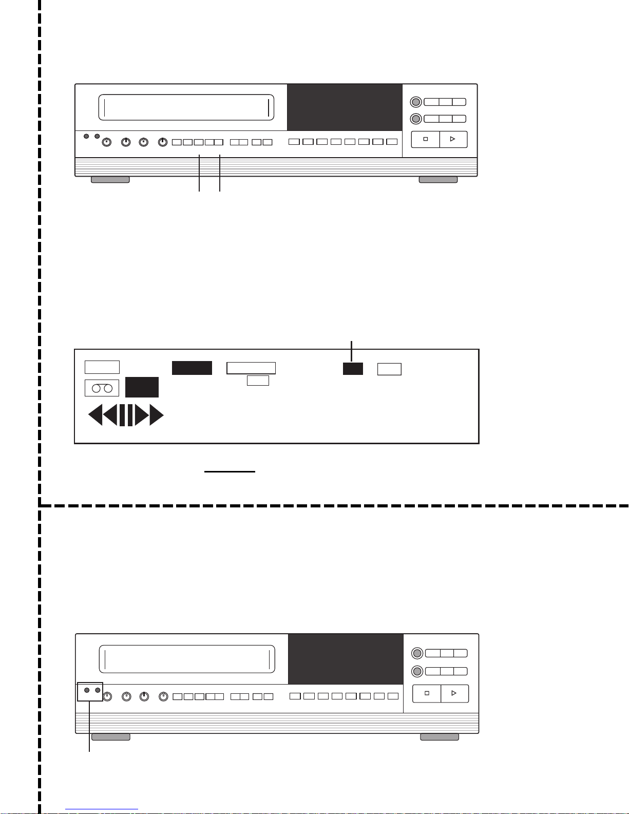
TO SET SECURITY LOCK (Locks out access to Recorder Programming)
Step 1. Press the NEXT and UP buttons at the same time.
Step 2. Check the digital display. The "Lock" Annunciator will light when the lock is activated. "L" will
appear below the Alarm Counter of the TIME/DATE stamp on the monitor.
Step 3. To deactivate security lock, press the NEXT and UP buttons at the same time. The "Lock"
annunciator will no longer be lit in the display. "L" will disappear from the TIME/DATE stamp
on the monitor.
LOCK ANNUNCIATOR
T
AB
REC
ALARM
INDEX
T
APE END
TIMER
B
0000
LOCK
SPEED
R
000
12-06-97 PL THU A04
08:28:44A 72 T L
LOCK INDICATOR IN
TIME/DATE STAMP
TO PERFORM A MASTER RESET
The MASTER RESET function is performed by inserting a pointed object into each of the Reset holes at
the same time. This is used to perform a MASTER RESET for abnormal Time Lapse system operations
such as T/D DISPLAY, Speed Select, etc. All programmable features must be reprogrammed after reset.
A MASTER RESET tool is supplied with this unit.
This unit is also equipped with a SYSTEM RESET function. The SYSTEM RESET function will NOT
change any of the menu settings. See "Tape Adjustment Controls: System Reset" for further information.
Note: A SYSTEM RESET may also be performed for Mecha Lock, Cyl Lock & Reel Lock. For more
information, contact factory.
FIELD
STILL FIELD
EJECT
REV
FWD
REVERSE
REW/
F. FWD/
PLAY
SEARCH
SEARCH
S
SHARPNESS 2-A24HR
TRACKING
SLOW
TRACKING
PROG. NEXT UP
PREV. DOWN
VLOCK
V-POS H-POS ALARM
INDEX
ALARM
RESET
COUNTER
RESET
REC / PLAY
HOURS
TIMER DAYLIGHT
SAVINGS
REC
STOP PLAY
ABC
END USER CARDDEALER CARD
RESET
HOLES
TLC2100
271-0498-4852503#

Contents
IMPORTANT NOTE ...........................................................................2
END USER CARD..............................................................................3
DEALER CARD ................................................................................3
IMPORTANT SAFEGUARDS .............................................................6
Cautions and Warnings .............................................................................................................................. 8
Precautionary Installation Steps ................................................................................................................. 8
Regular System Testing ............................................................................................................................. 8
Typical Security Installation with ATM or ECR ............................................................................................ 9
Typical Security System with a Camera Multiplexer ................................................................................. 10
PART ONE: GETTING STARTED.....................................................11
PART TWO: CONTROLS .................................................................12
OVERVIEW .................................................................................................. 12
FRONT PANEL CONTROLS......................................................................... 13
Cassette Compartment & Eject Button ..................................................................................................... 13
Tape and Picture Adjustment Controls ..................................................................................................... 13
Play/Record Operations Controls ................................................................................................ ............. 14
Programming Operation Controls ............................................................................................................. 15
Position & Alarm Controls ......................................................................................................................... 15
Timer & Miscellaneous Controls ............................................................................................................... 16
Digital Display........................................................................................................................................... 17
REAR PANEL FUNCTIONS.......................................................................... 19
INSTALLATION ........................................................................................... 20
Video & 15-Pin Connector Installation....................................................................................................... 20
Audio Installation ...................................................................................................................................... 21
RECORD CHECK ......................................................................................... 22
Rec Check................................................................................................................................................ 22
Record/Play Times ................................................................................................................................... 22
ALARM INDEX OPERATION........................................................................ 23
Alarm Index .............................................................................................................................................. 23
PART THREE: MENUS ....................................................................24
To Move and Edit in the Menus ................................................................................................................ 24
Main Menu................................................................................................................................................ 24
Time/Date Submenu................................................................................................................................. 25
Example of Setting the Clock & Navigating a Menu .................................................................................. 25
Display Options Submenu ........................................................................................................................ 26
Entering System Code Text ...................................................................................................................... 27
Text Position Submenu............................................................................................................................. 27
System Options Submenu ........................................................................................................................ 28
Timer Program Submenu ......................................................................................................................... 29
Alarms Submenu ...................................................................................................................................... 29
Alarm Record Options Submenu .............................................................................................................. 30
Alarm Memory Submenu .......................................................................................................................... 30
4
TLC 2100
271-0498-4852503#

Camera Switcher Pulse Submenu ............................................................................................................ 31
System Data Submenu............................................................................................................................. 31
PART FOUR: RS-232 OPTIONAL FEATURE.................................... 32
RS-232 FEATURE........................................................................................ 32
STD/Remote Port Menu ........................................................................................................................... 32
Remote Terminal Interface Commands .................................................................................................... 32
Operational Control Commands ............................................................................................................... 33
VCR Status Return Command.................................................................................................................. 33
VCR Extended Status Command ............................................................................................................. 33
Program Control Functions ....................................................................................................................... 34
Tape Speed Commands........................................................................................................................... 34
Extended Commands ............................................................................................................................... 35
Set Date Command .................................................................................................................................. 35
Read Date Command ............................................................................................................................... 35
Set Time Command.................................................................................................................................. 35
Read Time Command............................................................................................................................... 36
Set System Code Command .................................................................................................................... 36
Set Timer Program Command .................................................................................................................. 36
PART FIVE: DC OPTIONAL FEATURE ............................................37
Introduction............................................................................................................................................... 37
Installation ................................................................................................................................................ 37
Operation.................................................................................................................................................. 37
Battery Rating/Estimated Record Times Chart ......................................................................................... 37
Configuration 1: DC Installation - Frequent Usage.................................................................................... 38
Configuration 3: DC Installation With Trickle Charger ............................................................................... 38
Configuration 2: DC Installation-Infrequent Usage .................................................................................... 38
APPENDIX A: EXTERNAL INTERFACE .........................................39
Detailed Description of External Interface: 15-Pin "D" Connector ............................................................. 39
APPENDIX B: REMOTE CONTROL FEATURE.................................41
APPENDIX C: WARNING CODES.................................................... 42
Digital Display Codes................................................................................................................................ 42
Codes ....................................................................................................................................................... 43
APPENDIX D: PERIODIC MAINTENANCE AND TECHNICAL SUP-
PORT .......................................................................................... 44
APPENDIX E: TROUBLESHOOTING ...............................................45
APPENDIX F: SPECIFICATIONS .....................................................47
WARRANTY INFORMATION ...........................................................48
SALES ............................................................................................50
TECHNICAL SERVICE & SUPPORT ...............................................50
EUROPEAN INFORMATION ............................................................50
ASIA PACIFIC INFORMATION ........................................................ 50
TLC 2100
271-0498-4852503#
5

IMPORTANT SAFEGUARDS
In addition to the careful attention devoted to quality standards in the manufacture of your video
product, safety is a major factor in the design of every instrument. But safety is your responsibility, too.
These pages list important information that will help to assure proper use of a Video Cassette
Recorder and accessory equipment. Please read it carefully before operating your video product
and keep it in a handy place for future reference.
1. USE HIGH QUALITY HIGH GRADE VHS CASSETTES - High resolution time
lapse recording requires a high quality high grade tape for satisfactory performance. Some brands of tape can have an adverse effect on video head performance
and head life. The following brands have been found to meet our critical specifications:
GYYR BASF MAXELL TDK
2. READ INSTRUCTIONS - All of the safety and operating instructions should be
read before the appliance is operated.
3. RETAIN INSTRUCTIONS-The safety and operating instructions should be retained for future reference.
4. HEED WARNINGS-All warnings on the appliance and in the operating instructions should be adhered to.
5. FOLLOW INSTRUCTIONS-All of the “operating and use” instructions should be
adhered to.
6. GROUNDING-This video product is equipped with a 3-wire grounding- type plug
[A plug having a third pin for grounding.] This plug will only fit into a groundingtype power outlet. This is a safety feature. If you are unable to insert the plug into
your outlet, contact your electrician to replace your obsolete outlet. Do not attempt
to defeat the safety purpose of the grounding-type plug.
7. POWER SOURCES-This video product should be operated only from the type of
power source indicated on the marking label. If you are not sure of the type of power
you are using, consult your video dealer or local power company.
8. OVERLOADING-Do not overload wall units and extension cords, as this can result
in a risk of fire or electric shock. Frayed power cords, damaged or cracked wire
insulation and broken plugs are dangerous. Periodically examine the cord and
have it replaced by your service technician if appearance indicates damage or
deteriorated insulation.
9. POWER-PLUG PROTECTION-The power-supply cords should be routed so they
are not likely to be walked on or pinched by items placed upon or against them. Pay
particular attention to cords at the plug, convenience receptacles, and the point
where the cord exits from the video product.
10.VENTILATION-Slots and opening in the cabinet are provided for ventilation and
to ensure reliable operation of the video product and to protect it from overheating.
Therefore, these openings must not be blocked or covered. The openings should
never be blocked by placing the video product on a bed, soft rug, or other similar
surface. This video product should not be placed in a built-in installation such as
bookcase or rack unless proper ventilation is provided or the manufacturer’s
instructions have been followed.
11. ATTACHMENTS-Do not use attachments other than those specifically recommended by the video product manufacturer as they may cause hazards.
6
CAUTION: Maintain electrical safety. Powerline operated equipment or accesso-
ries connected to this unit should bear the UL listing mark or CSA certification mark
on the accessory itself and should not have been modified so as to defeat the safety
features. This will help avoid any potential hazard from electric shock or fire. If in
doubt, contact qualified service personnel.
TLC 2100
271-0498-4852503#

12. TO PREVENT SHOCK HAZARD, DO NOT EXPOSE THIS UNIT TO RAIN OR
MOISTURE. If you spill liquid on the unit, consult authorized service personnel.
Moisture can damage internal parts. Do not use this recorder near sources of
water.
13. ACCESSORIES-Do not place this video product on an unstable: cart, stand,
tripod, bracket, or table. The video product may fall, causing serious injury to a
child or adult, and serious damage to the appliance. Use only with a cart, stand,
tripod, bracket, or table recommended by the manufacturer. Any mounting of the
video product should follow the manufacturer’s instructions, and should use a
mounting accessory recommended by the manufacturer.
13a.Appliance and cart combination should be moved with care. Quick stops,
excessive force, and uneven surfaces may cause the appliance and cart combination to overturn.
14. CLEANING THE OUTSIDE SURFACES-Unplug this video product from the
wall outlet before cleaning. Do not use liquid of aerosol cleaners. Use a damp cloth
for cleaning.
15. OBJECT AND LIQUID ENTRY-Never push objects of any kind into this video
product through openings as they may touch dangerous voltage points or short
out parts that could result in a fire or electric shock. Never spill liquid of any kind
on the video product.
16. SERVICING-Do not attempt to service this video product yourself. Opening or
removing covers may expose you to dangerous voltage or other hazards. Refer all
servicing to qualified service personnel.
17. CONDITIONS REQUIRING SERVICE-Unplug this video product from the
wall outlet and refer servicing to qualified service personnel under the following
conditions:
a. When the power cord or plug is damaged.
b. If liquid has been spilled into the video product.
c. If the video product has been exposed to rain or water.
d. If the video product does not operate normally by following the instructions.
Adjust only those controls that are covered by the operating instructions. The
adjustment of other controls may result in damage and will often require
extensive work by a qualified technician to restore the video product to its
normal operation.
e. If the video product has been dropped or the cabinet has been damaged.
f. When the video product exhibits a distinct change in performance - this
indicates a need for service.
TLC 2100
271-0498-4852503#
18. REPLACEMENT PARTS-When replacement parts are required, be sure the
service technician has used replacement parts specified by the manufacturer or
have the same characteristics as the original past. Unauthorized substitutions
may result in fire, electric shock, or other hazards and void the warranty.
19. SAFETY CHECK-Upon completion of any service or repairs to this video product,
ask the service technician to perform safety checks to determine that the video
product is in safe operating condition.
20. IMPORTANT NOTE TO THE INSTALLER-This installation should be made by
a qualified ervice person and should conform to all local codes.
In order to provide this product with protection against risk of unintentional
operation by employees, customers, janitors and cleaners working on the premises, and from falling falling objects, building vibrations and similar causes, it
is recommended:
• that this product be enclosed in a tamper-resistant lockbox. Make sure that the
lockbox is well ventilated or maintained with an air cooling system.
• that security locking procedures described on the detachable yellow card at the
front of this manual be followed.
7

Cautions and
Warnings
This product can be used in a mercantile bank to provide positive visual identification
of suspects by recording surveillance video camera images and time and date information onto permanent magnetic media (video tape). The time-lapse video cassette
recorder and all other components of the surveillance system must be properly
installed, tested, and maintained to fulfill this function. Carefully follow the instructions presented here and elsewhere in the manual.
High resolution time-lapse recording requires high quality tape for satisfactory
performance. The following brands meet the manufacturer’s critical specifications:
• GYYR
• BASF
• MAXELL
• TDK
Precautionary
Installation Steps
Regular System
Testing
1. Secure surveillance equipment to prevent unauthorized access.
2. Supply secure power to all system components. Dedicate power circuits to
surveillance equipment to prevent overloading or shorting the circuits. Limit
access to the surveillance system circuits breakers, switches, and equipment
power cords.
3. Ensure all surveillance system components are operationally compatible. Dwell
times of any accessory switching equipment must be compatible with time lapse
recording speeds.
4. Carefully plan the alarm triggering of components to ensure compatible operation
(alarm hold, duration, sequencing, etc.) Alarms may be recorded at all speeds.
The 2 hour speed records more pictures, providing an increased chance of
capturing a subject’s face on tape. However, more tape will be used in the process.
There is a greater chance the video cassette will run out of tape, especially if alarms
occur frequently. The time-lapse speeds record fewer pictures, but can record
longer without tape changes. Because time-lapse recording methods are used, the
speed of the recording has no effect on image resolution.
5. Thoroughly test the completed surveillance system installation before use. Perform test recordings at the time-lapse speeds to be used and test system performance
under alarm conditions. Test any power backup system installed by interrupting
electrical power. Playback the test recordings to confirm the picture quality is
adequate and the time/date display is visible under both normal and alarm
conditions.
1. Check the operation of the surveillance system at least once a day. Verify tape
movement by watching the counter number increment. Check that the monitor
is displaying camera video with time date information, and that any camera
sequencing is working properly. Perform the REC CHECK (see page 19 for more
information) function and be sure that you see two separate, sequential playback
images on the monitor, approximately 1 second apart.
8
2. Check to see if any alarms have been recorded, since multiple alarms could cause
the video cassette to run out earlier than expected. There should always be
enough video tape remaining on the cassette to record at least 5 minutes of activity
at the selected alarm speed.
3. Perform the following tests on a regular basis: Playback a tape recently recorded
under normal conditions by the system to confirm picture quality. Manually
trigger an alarm condition to check for proper alarm mode operation. Play back
the alarm test recording to confirm operation and picture quality.
4. Use the manufacturer's recommended video tape and replace it regularly (10-15
passes maximum). Check tapes for head scarring and replace any damaged tapes.
Handle tapes carefully and store them in their boxes. Keep the tapes away from
dust, magnetic fields, excessive heat, and direct sunlight.
TLC 2100
271-0498-4852503#
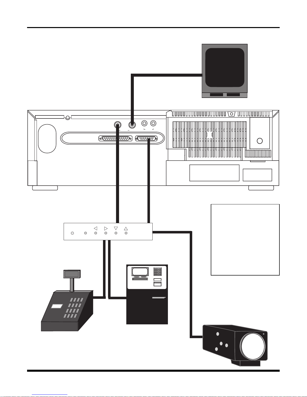
Typical Security
Installation with
ATM or ECR
d
Video In
IN VIDEO OUT
Alarm
e
Port
c
V
IN OUT
AUDIO
ideo Out
b
Monitor
Electronic
Cash
g
Register
RS-232
f
Text Inserter
POWER
PRGM PREV NEXT DOWN UP
OR
EZ Bank ATM
Automated
h
Teller
Machine
The diagrams on these two
pages depict typical installations at a security system site.
For detailed installation
and rear panel interface
information, see "Rear
Panel Functions," page 16
"Installation," page 17.
Video Camera
i
TLC 2100
271-0498-4852503#
9
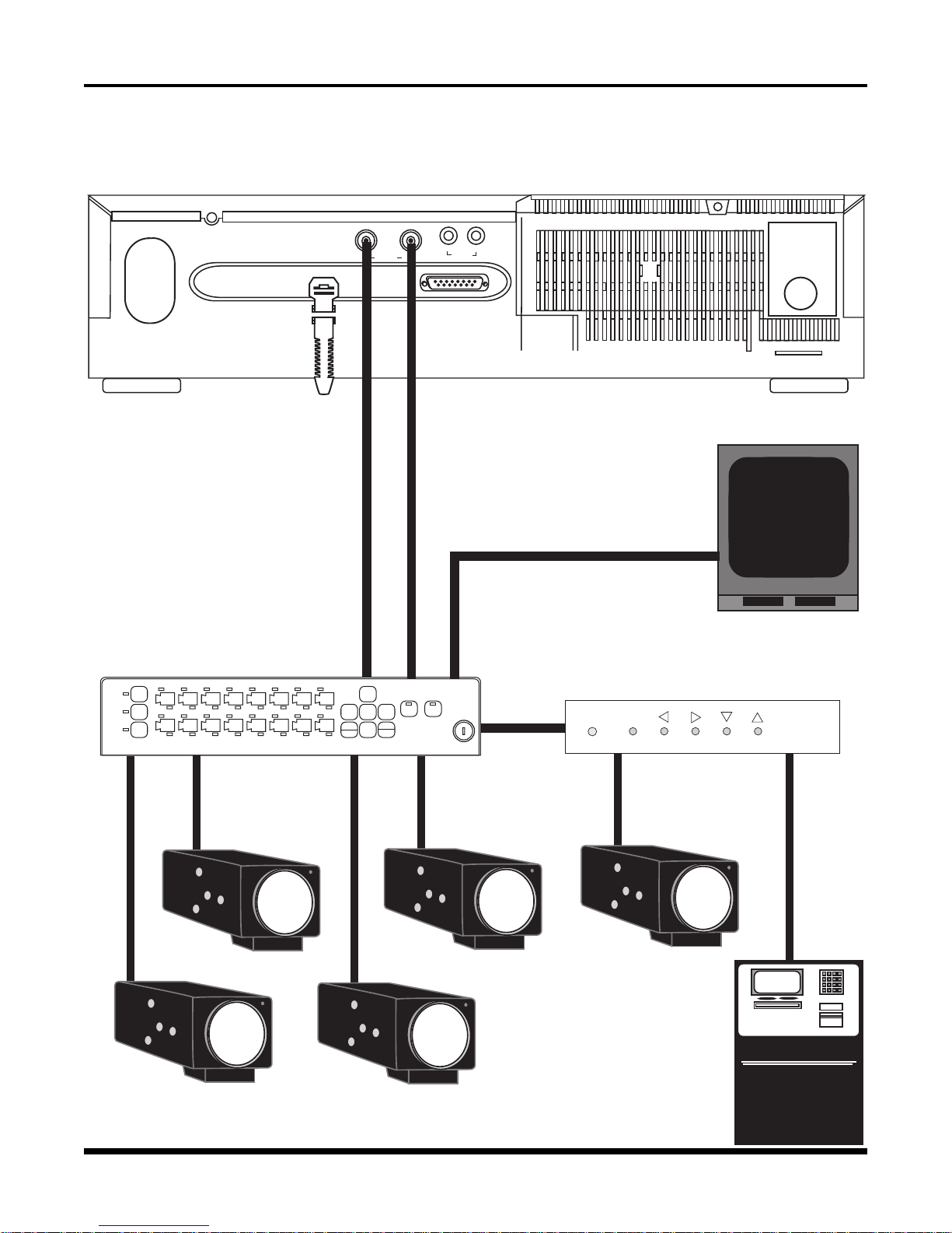
Typical Security
System with a
Camera
Multiplexer
c
- Video In
IN VIDEO OUT
IN OUT
AUDIO
b
- Alarm
Port
d
- Video Out
e
- Monitor
f
- Camera Multiplexer
FREEZE
1 2 3 4 5 6 7 8
DISPLAY
SELECT
9
TIME
LAPSE
h
→
RECORD PLAY
MENU
→
→
→
NEXT
PREVIOUS
16151413121110
ENLARGE
VIEW
- Video Camera
g
- RS-232
Text Inserter
POWER
PRGM PREV NEXT DOWN UP
i
- Automated
Teller
Machine
EZ Bank ATM
10
TLC 2100
271-0498-4852503#

PART ONE: GETTING STARTED
If you have never used a time-lapse recorder system before, this section will explain
what you need to do to get started.
Besides your time-lapse recorder, you will need the following equipment:
• a video camera
• a monitor
• cables for the camera and monitor (typically these are coax cables with BNC connectors)
• a T-120 or T-130 VHS video tape. We recommend the following brands of tapes:
Gyyr, BASF, Maxell and TDK.
• power sources for the VCR, camera, and monitor.
Before connecting any piece of equipment to a power source, make the following
connections (consult page 17 of this manual for a diagram of these connections;
however, for this example, we will not connect an alarm panel as shown in the diagram.
You may also wish to consult the diagram of the VCR's Rear Panel on page 16):
• connect the camera to the VCR's Video In connector
• connect the monitor to the VCR's Video Out connector
• plug in all of your equipment to their power sources. This VCR unit connects into a
120 VAC wall outlet
• insert the video tape into the unit
Your monitor should now display your camera's image. You will also see a Time/Date
display on the monitor with its factory default setting. A flashing message will be
displayed: "Set Clock".
If you wish to program the Time/Date Display, see pages 22 -23 of this manual. A stepby-step description is covered in that section.
You will also notice that the letters "PL" are flashing in the Time/Date display. "PL"
stands for Power Loss. To remove "PL" from the display, simply press the Alarm Rest
button (see page 12 for more information). However, be aware as you learn about the
more advanced functions of your VCR, that pressing the Alarm Reset button will also
clear the alarm memory.
If you wish to display the VCR's On-Screen Menus, press the Prog. button. Information
about all the Programming Buttons is found on page 12 of this manual. Information
about the VCR's On-Screen Menus is found in Part 3 of this manual.
If you wish to learn more about the Front Panel Controls, you might begin with the
Play/Record Operation Controls. Information about these controls is found on page 11.
These controls are somewhat similar in operation to those of a home VCR.
As you are operating your recorder, keep an eye on the Digital Display (see pages 14
& 15 for more information) and become familiar with the various indicators. This
display will become invaluable as you become more comfortable with the operation of
your recorder.
If you have questions about the operation of this unit, contact your local dealer or call
one of the phone numbers listed on the back cover of this manual for expert assistance.
TLC 2100
271-0498-4852503#
11
PART TWO: CONTROLS
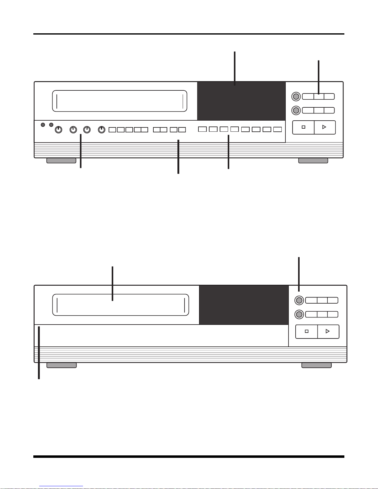
OVERVIEW
S
SHARPNESS 2-A24HR
Tape & Picture
Adjustment Controls
TRACKING
SLOW
TRACKING
Digital Display
PREV. DOWN
PROG. NEXT UP
VLOCK
V-POS H-POS ALARM
INDEX
ALARM
RESET
RESET
HOURS
TIMER DAYLIGHT
ABC
SAVINGS
COUNTER
REC / PLAY
Programming and Timer
Operations Controls
Front Panel with Control Compar tment Open
Record / Play
Operations
Controls
FIELD
EJECT
REC
STILL FIELD
REV
REVERSE
REW/
PLAY
SEARCH
STOP PLAY
FWD
F. FWD/
SEARCH
Cassette
Compartment
Gently pull forward
here to open panel
Tape
Eject
Button
EJECT
REC
STOP PLAY
FIELD
REV
REVERSE
PLAY
STILL FIELD
REW/
F. FWD/
SEARCH
SEARCH
FWD
Front Panel with Control Compar tment Closed
12
TLC 2100
271-0498-4852503#
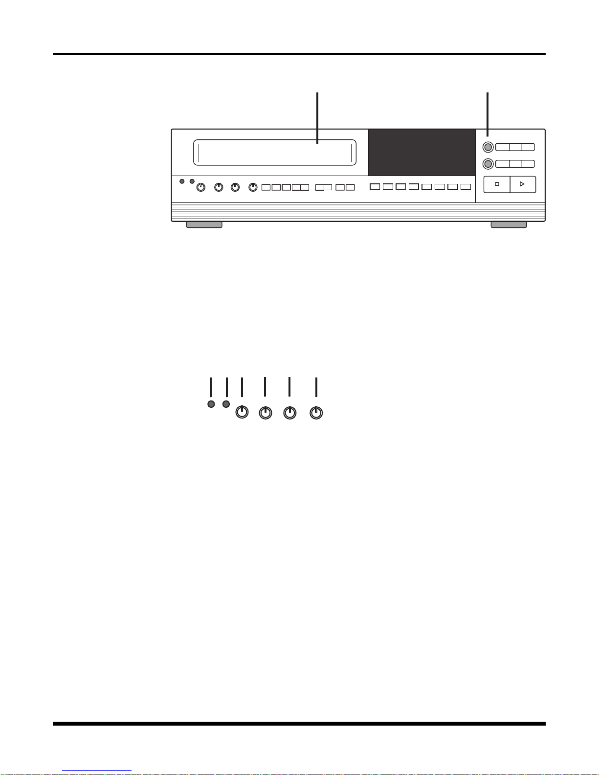
FRONT PANEL CONTROLS
Cassette
Compartment &
Eject Button
S
SHARPNESS 2-A24HR
1 FRONT PANEL LOADING CASSETTE COMPARTMENT
Insert a VHS video tape cassette into this compartment.
2 TAPE EJECT BUTTON
Press to remove the cassette. The Eject Button will not operate in the RECORD
mode.
TRACKING
SLOW
TRACKING
PREV. DOWN
PROG. NEXT UP
VLOCK
bc
FIELD
STILL FIELD
EJECT
REV
FWD
REVERSE
REW/
F. FWD/
PLAY
SEARCH
SEARCH
V-POS H-POS ALARM
INDEX
ALARM
RESET
COUNTER
RESET
REC / PLAY
HOURS
TIMER DAYLIGHT
SAVINGS
REC
STOP PLAY
ABC
Tape and Picture
Adjustment
Controls
DEF
S
SHARPNESS
2-A24HR
TRACKING
HG
SLOW
TRACKING
I
VLOCK
3 SEE "STOP" INSERT CARD AT FRONT OF THE MANUAL
4 SYSTEM RESET
Insert a reset tool into this hole (marked "S") to reset unit without changing menu
settings. This function will reset the unit for warning errors (see Appendix C:
Warning Messages").
5 SHARPNESS
Use this control to adjust picture sharpness during playback.
6 2-A24 HOUR TRACKING
Adjust to optimize the picture quality playback speeds of 2 to A24 hours.
7 SLOW TRACKING
Adjust to optimize the picture quality during slow playback speeds, that is, speeds
of 24 hours and over.
8 V-LOCK
Adjust this control to reduce vertical jitter in time-lapse Playback (18-hour through
960-hour speeds) and STILL mode.
TLC 2100
271-0498-4852503#
13
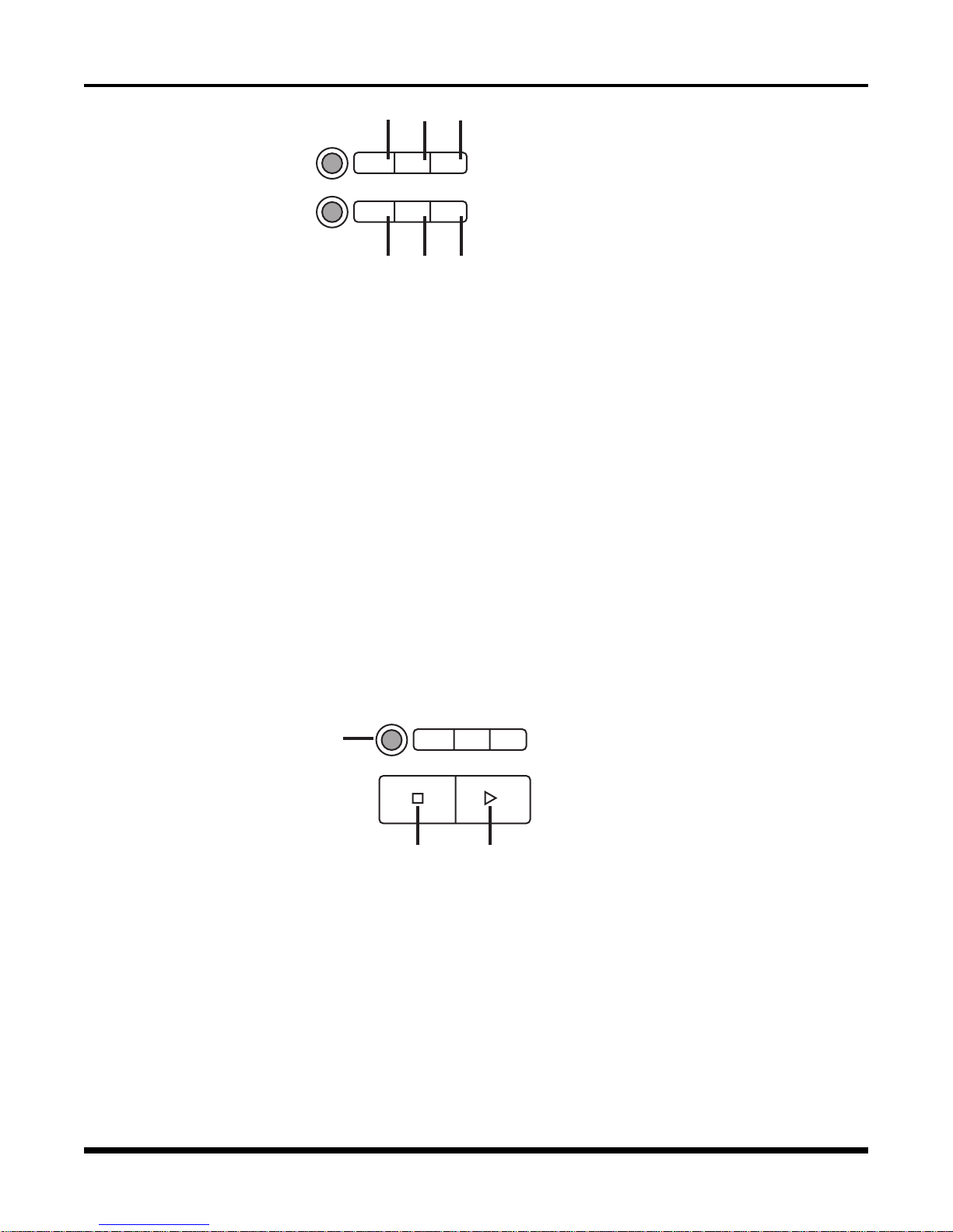
Play/Record
Operations
Controls
EJECT
REC
j1)1!
FIELD
REV
REVERSE
PLAY
STILL
REW/
SEARCH
FIELD
SEARCH
FWD
F. FWD/
For the Best Results
When Reviewing a
Time-Lapse Recorded
Tape:
1. With the VCR in
PLAY (#16), and without a particular event
in mind, place the VCR
in the 2 hour speed.
This is the fastest playback speed and can
usually be used quickly
to locate an event.
2. Once an event has
been identified, slow
the unit to 30 hr., 48 hr.
or any other slower
speed. These slower
speeds will allow close
examination of the
situation and ample
time to react.
3. Select the STILL
(#10) mode to stop the
tape. Use FIELD FWD
(#11) or FIELD REV (#9)
to get the exact field
you wish to review.
1@ 1#
1$
9 FIELD REVERSE
Press to reverse the tape by one field in the STILL playback mode.
10 STILL
Press to temporarily stop tape motion in the PLAY mode.
11 FIELD FORWARD
Press to advance the tape one field in the STILL playback mode.
12 REVERSE PLAY
Press to play recorded material at 02, 72, 120, 180, 240, 360, 480, 600, 720, or 960
hours, in reverse during the PLAY mode.
13 REWIND/SEARCH
Press to rewind. If pressed during PLAY mode, the recorder will perform a high
speed reverse playback (search). Search speeds are variable and selectable. See
"System Options: Search Speed" for more information.
14 FAST FORWARD/SEARCH
Press to activate fast forward. If pressed during PLAY mode, the recorder will
perform a high speed forward playback (search). Search speeds are variable and
selectable. See "System Options: Search Speed" for more information.
REVERSE
REW/
REC
PLAY
SEARCH
F. FWD/
SEARCH
1&
STOP PLAY
1%
1^
15 STOP
Press to stop the tape. This button must be pressed to end the RECORD mode.
16 PLAY
Press to play recorded material. PLAY speeds are 02, A18, A24, 24, 48, 72, 120, 180,
240, 360, 480, 600, 720, and 960 hours. The Play button is also used for the Record
Check function (see page 19 for more information).
17 RECORD
Press to start recording. RECORD speeds are 00, 02, 18, 24, 48, 72, 120, 180, 240,
360, 480, 600, 720, and 960 hours.
14
TLC 2100
271-0498-4852503#

Programming
Operation
Controls
Position & Alarm
Controls
1(
2$
2)
2!
2% 2^
2@
1*
18 PROG. (PROGRAM) BUTTON
Press to display Main Menu. Also used for various Menu functions. See "To Move
and Edit in the Menus" page 21 for more information about all the programming
control buttons.
19 PREV. (PREVIOUS) BUTTON
Press to go back to last displayed function or value.
20 NEXT BUTTON
Press to go to the next function or value to be displayed.
21 DOWN BUTTON
Press to change to a lower value or to move to next line in a menu.
22 UP BUTTON
Press to change to a higher value or to move to the previous line in a menu.
2#
Note: V-POS and H-POS
operate independently
of the Text Position
settings in the Display
Options submenu. It is
possible that the POS
and Display Options
settings may conflict
with each other. See
"Display Options
Submenu" for further
information.
Note also that the Text
Position setting allow
you to set the individual
positions of the Date,
Time, and System Code
lines, whereas V-POS
and H-POS move these
three lines as a group.
23 V-POS (VERTICAL POSITION) BUTTON
Press repeatedly to control the vertical position of the Time / Date display.
24 H-POS (HORIZONTAL POSITION) BUTTON
Press repeatedly to control the horizontal position of the Time / Date display
25 ALARM SEARCH INDEX BUTTON
Press to activate Alarm Search Index function. See "Alarm Index" for more
information.
26 ALARM RESET BUTTON
Press to clear all ALARM and POWER LOSS information.
The first press clears "PL" in the Time/Date stamp (if this condition exists).
The second press (first press if there is no Power Loss) clears the Alarm Memory
menu list (see page 27 for more information).
TLC 2100
271-0498-4852503#
15
 Loading...