

Gyyr DVMS 400 Operating Instructions Manual

Gyyr DVMS 100b.qxd 03/08/2000 3:14 PM Page i
Copyright and Trademark Information
Copyright
This document, the Gyyr DVMS 100 and all related materials are
© Copyright 2000, Gyyr, Inc. All rights reserved.
Trademarks
The Gyyr DVMS 100 is a trademark of Gyyr, Inc. All other trademarks
are property of their respective holders.
Caveats
Information in this document is subject to change without notice.
Installation of the DVMS 100 requires technical and mechanical ability
and requires precautions against electrostatic discharge. The user
assumes all risks when this product is installed by anyone other than an
authorized Gyyr dealer.
Gyyr DVMS 400a.qxd 02/11/2000 3:45 PM Page ii
Gyyr DVMS 400 User’s Guide
IMPORTANT NOTES:
You should not remove the cover of your DVMS 400.
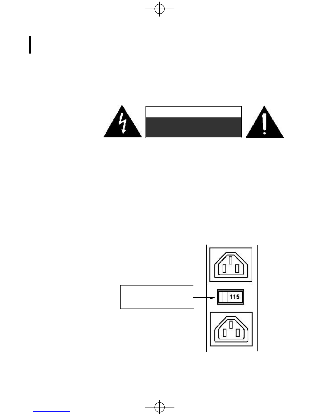
CAUTION
RISK OF ELECTRIC SHOCK
DO NOT OPEN
If your DVMS 400 requires repair please contact Gyyr.
WARNING: The DVMS 400 is intended for indoor use. To
reduce a risk of fire or electric shock, do not expose this
product to rain or moisture.
The DVMS 400 has a switching power supply (115/230 V). It is
shipped with the correct voltage setting for your location. When
you remove the protective sticker from the back of your unit
check the voltage setting before plugging in your unit.
Check this switch for the
correct voltage setting
for your location.


Gyyr DVMS 400a.qxd 02/11/2000 3:45 PM Page iii
TABLE OF CONTENTS
Introduction . . . . . . . . . . . . . . . . . . . . . . . . . . . . . . . . . . . . . . . . . . . . . . . . . . .1
The Gyyr DVMS 400 .........................................................................................................1
Features ...............................................................................................................................2
Sample Setup.......................................................................................................................4
Table of Contents
Chapter 1: Installing the DVMS 400 System . . . . . . . . . . . . . . . . . . . . . . . . .5
Hooking Up Your Equipment .............................................................................................5
Video Cameras .....................................................................................................5
Video Monitor .......................................................................................................6
Microphone ...........................................................................................................6
Speaker .................................................................................................................6
Text Insertion Ports ..............................................................................................6
Alarm Inputs .........................................................................................................6
Alarm Output ........................................................................................................7
Arm Alarm and Alarm Reset ................................................................................7
Remote Access Port (EIA-232) .............................................................................7
SCSI Connector ....................................................................................................8
PC Card Slot ........................................................................................................8
Cables ...................................................................................................................8
Using the Setup Program ....................................................................................................9
Using the Cursor Controls ...................................................................................9
Entering the Setup Program ...............................................................................11
Exit Function ......................................................................................................12
Change Password ...............................................................................................12
Calendar .............................................................................................................14
Setting Recording Times for a Day ....................................................................14
Using Holiday Setup ..........................................................................................15
Using Normal/Alternate Setup ...........................................................................16
Setting Alternate Time-Lapse and Pre-Event Mode ...........................................17
Clock Set .............................................................................................................19
Disk .....................................................................................................................20
Reports ................................................................................................................24
Creating a new report ........................................................................................24
Text Criteria .......................................................................................................25
i

Gyyr DVMS 400a.qxd 02/11/2000 3:45 PM Page iv
Gyyr DVMS 400 User’s Guide
Event Criteria .....................................................................................................26
Deleting a Report ...............................................................................................27
Editing a Report .................................................................................................27
Executing a Report .............................................................................................27
Review Events .....................................................................................................30
VCR Setup (Optional) ........................................................................................31
Install ..................................................................................................................32
Service ................................................................................................................32
Default Settings ..................................................................................................33
System Info .........................................................................................................33
Remote Access ....................................................................................................34
System Log ..........................................................................................................36
Download Software ............................................................................................36
User Preferences ................................................................................................37
Switcher ..............................................................................................................38
Video In ...............................................................................................................39
Text In .................................................................................................................40
Alarm Inputs .......................................................................................................41
Time-Lapse Recording ........................................................................................42
Event Recording .................................................................................................44
General Setup .....................................................................................................44
Arming Setup ......................................................................................................45
Text Events ..........................................................................................................45
Alarm Events ......................................................................................................47
Motion Events .....................................................................................................49
Pre-Event Recording ..........................................................................................53
Setup Functions: A Reference Map ..................................................................................56
Chapter 2: Operation . . . . . . . . . . . . . . . . . . . . . . . . . . . . . . . . . . . . . . . . . .59
Overview ...........................................................................................................................59
Live Monitoring ................................................................................................................59
Recording Video: Time Lapse and Event Recording .......................................................60
Event Handling .................................................................................................................60
Playing Video Clips ..........................................................................................................62
Normal Play Screen ............................................................................................62
Normal Play Screen: Time-lapse ........................................................................64
Simple Play Screen .............................................................................................65
Archiving Clips ...................................................................................................66
Searching for Video Clips .................................................................................................67
Recording to Video Tape ..................................................................................................68
Printing Video Still Images ...............................................................................................68
ii

Gyyr DVMS 400a.qxd 02/11/2000 3:45 PM Page v
Chapter 3: Software Update Utility . . . . . . . . . . . . . . . . . . . . . . . . . . . . . . .69
Overview ...........................................................................................................................69
Software Update Utility ....................................................................................................70
Installing the Software Update Utility ...............................................................70
Attaching the Null Modem Cable .......................................................................70
Setting Up DVMS 400 ........................................................................................70
The New Software ...............................................................................................70
Downloading The Updated Software .................................................................71
Windows Com Port Speed ................................................................................................72
CHAPTER 4: Remote Access Software (RAS) . . . . . . . . . . . . . . . . . . . . . . .73
Overview ...........................................................................................................................73
Minimum Computer System Requirements ........................................................73
Setting up the DVMS 400 Unit ...........................................................................74
RAS Software Installation .................................................................................74
Connecting to DVMS 400 ................................................................................................75
Hooking-up the Equipment ................................................................................75
Starting the Gyyr RAS ........................................................................................76
Creating an Ethernet Connection ......................................................................76
Creating a Modem or Null Modem Connection ................................................77
Windows NT Phonebook Entry ...........................................................................79
Windows 95/98 Modem Properties ....................................................................81
Login ...................................................................................................................83
Using Gyyr RAS without Connecting .................................................................84
Monitoring Video Using RAS ..........................................................................................84
Video Monitoring Controls .................................................................................85
Recording Video Monitor Images ......................................................................86
Controlling DVMS 400 with RAS ...................................................................................88
Record .................................................................................................................88
Setup ...................................................................................................................88
Configuration Files ............................................................................................88
Help ....................................................................................................................89
Search .................................................................................................................89
Play .....................................................................................................................91
Archiving Clips ...................................................................................................91
Playing Downloaded Video Files .....................................................................................92
Using a Non-MMX Processor ..........................................................................................93
Downloading DVMS 400 Software Using RAS ..............................................................93
Disconnecting from the DVMS 400 .................................................................................94
Table of Contents
iii

Gyyr DVMS 400a.qxd 02/11/2000 3:45 PM Page vi
Gyyr DVMS 400 User’s Guide
Chapter 5: Video Formats and Digital Video . . . . . . . . . . . . . . . . . . . . . . .95
Frames and Fields .............................................................................................................95
NTSC and PAL .................................................................................................................95
Composite Video and S-Video .........................................................................................96
Hard Disk Speed – Throughput ........................................................................................97
Compression .....................................................................................................................97
Wavelet Compression .......................................................................................................99
Audio Compression ..........................................................................................................99
Appendix A: Modem and Null Modem Connections . . . . . . . . . . . . . . . . .101
Overview .........................................................................................................................101
Windows 95 / 98 .............................................................................................................102
Dial-Up Networking .........................................................................................102
Installing a Modem ..........................................................................................106
Installing a Null Modem ..................................................................................107
Creating a DVMS 400 Modem Connection .....................................................109
Windows NT ...................................................................................................................112
Installing a Modem ...........................................................................................112
Installing a Null Modem ...................................................................................113
Dial-up Networking ..........................................................................................116
Creating a Phonebook Entry ............................................................................118
Appendix B: Gyyr DVMS 400 Specifications . . . . . . . . . . . . . . . . . . . . . . . .123
Appendix C: Compliance and Conformity . . . . . . . . . . . . . . . . . . . . . . . . . .127
Index . . . . . . . . . . . . . . . . . . . . . . . . . . . . . . . . . . . . . . . . . . . . . . . . . . . . . . . . . .131
iv
Gyyr DVMS 400a.qxd 02/11/2000 3:45 PM Page 1
INTRODUCTION
The Gyyr DVMS 400
Introduction
The Gyyr DVMS 400 is the heart of your digital video time-lapse/event
recorder CCTV system. Its many features include 4 video inputs, 4 built-in
text inserters, a quad splitter (to allow viewing of four camera images at the
same time on one monitor), a sequencing switcher (to allow 4 cameras to be
monitored sequentially), 4 alarm inputs, and a 4-channel video motion
detector.
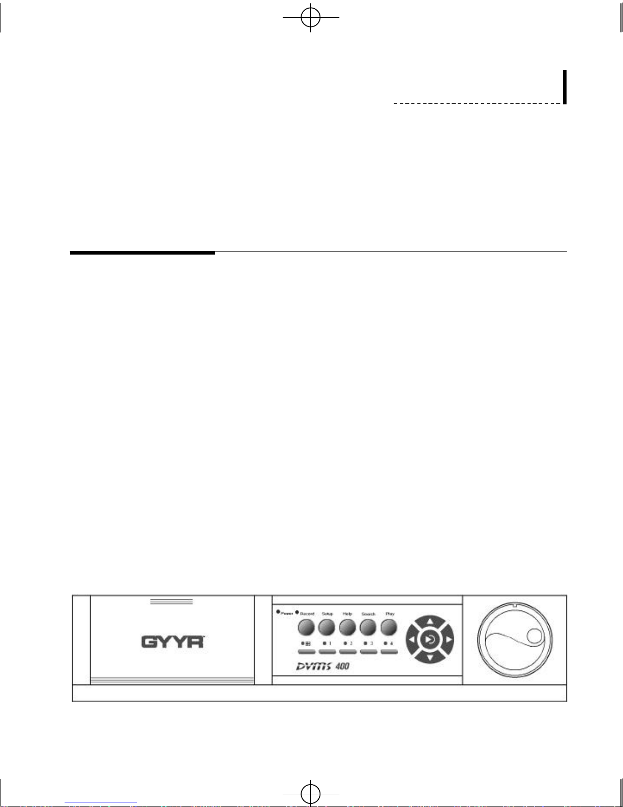
Front View
The Gyyr DVMS 400 digitizes video and audio signals and records them on
to a disk drive. This digital recording and playback system replaces the
standard analog VCR and video tape. System reliability is improved as
stretchable video tape, tape heads and tape transport are all eliminated from
the digital system. This digital system has the added advantages of allowing
text searches and fast retrieval of any video image (without waiting for the
tape to rewind or fast forward). The digital image is encoded to prevent
image tampering. A password ensures authorized access only.
The DVMS 400 has a graphical on-screen setup program which can be
operated using the cursor controls on the front panel. The settings are very
flexible, allowing each user to customize the product to suit their individual
needs. Once it has been set up the DVMS 400 is very easy to use, with just
a few buttons controlling all normal operations.
1
Gyyr DVMS 400a.qxd 02/11/2000 3:45 PM Page 2
Gyyr DVMS 400 User’s Guide
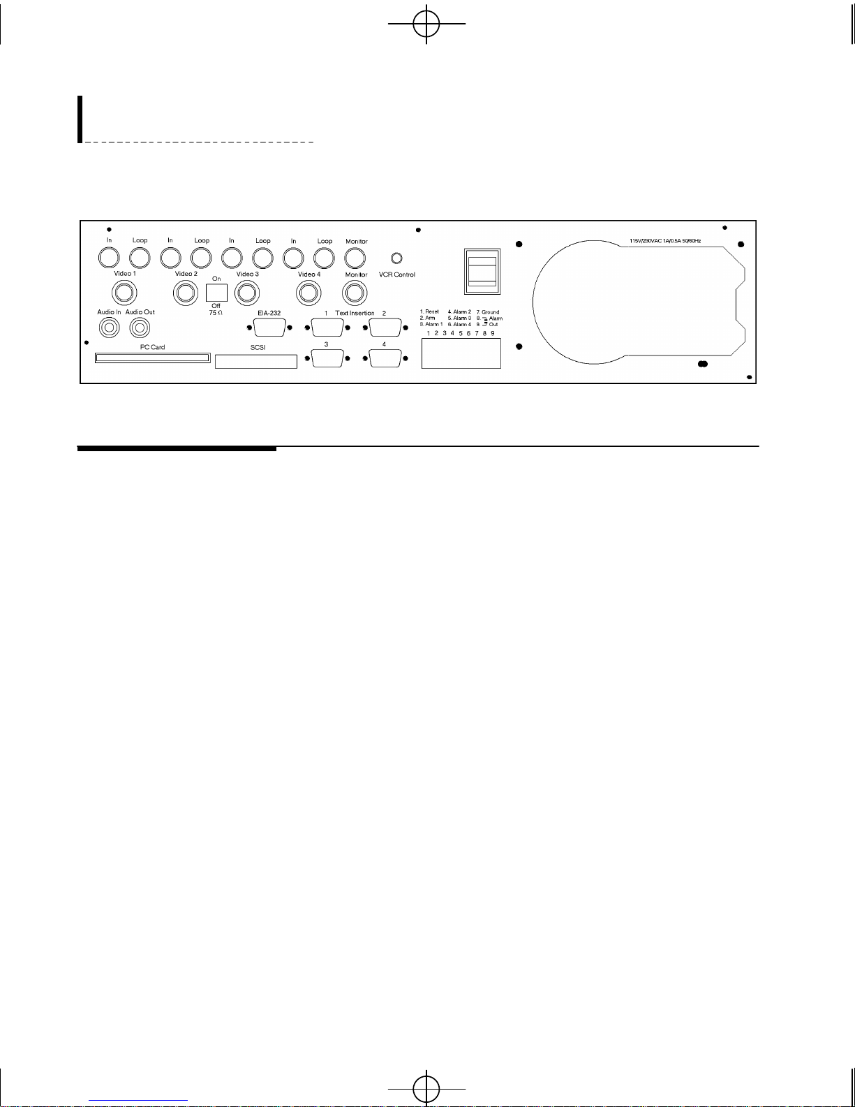
Rear View
Features
• Time-lapse to real-time video recording
• Recording speeds adjustable from 0.05 field/second (1 field per 20
seconds) to 60 fields/second (NTSC) and 50 fields/second (PAL)
• Audio recording at all speeds
• Adjustable playback speeds
• 4 video inputs: Composite with loop-through or S-Video
• Automatic color/monochrome detection
• Alarms for loss of video input
• 4 alarm inputs, one alarm output, plus Arm and Reset
• 4 channel motion detection, each with up to 4 zones
• Virtually unlimited alarm conditions memory
• Full NTSC or PAL resolution (720x486 per frame for NTSC, 720x576
• Built-in Quad splitter
2
per frame for PAL)

Gyyr DVMS 400a.qxd 02/11/2000 3:45 PM Page 3
Introduction
• 4 channel text insertion for use with devices such as ATMs and
electronic cash registers
• Video searchable by captured text content, date/time, event type
• On-screen color graphical user interface
• On-line, on-screen help
• Non-volatile programming (settings are not lost in case of power loss)
• Encoded image authentication to prevent forgeries or tampering
• Date/Time “burned” into every image
• Electronic lock-out without proper password
• Infra red universal remote control of consumer VCRs (optional)
• Record to video tape according to a user defined schedule
• Maximum of 7 SCSI-2 drives (2 internal maximum)
• Support for removable drives (such as the iomega Jaz drive)
• Support for DVD drives
• Remote access via a 9-pin EIA-232 port
• PC Card slot (PCMCIA) for communication needs using dial-up
modems, Ethernet network cards, software upgrades, etc.
3
Gyyr DVMS 400a.qxd 02/11/2000 3:45 PM Page 4
Gyyr DVMS 400 User’s Guide
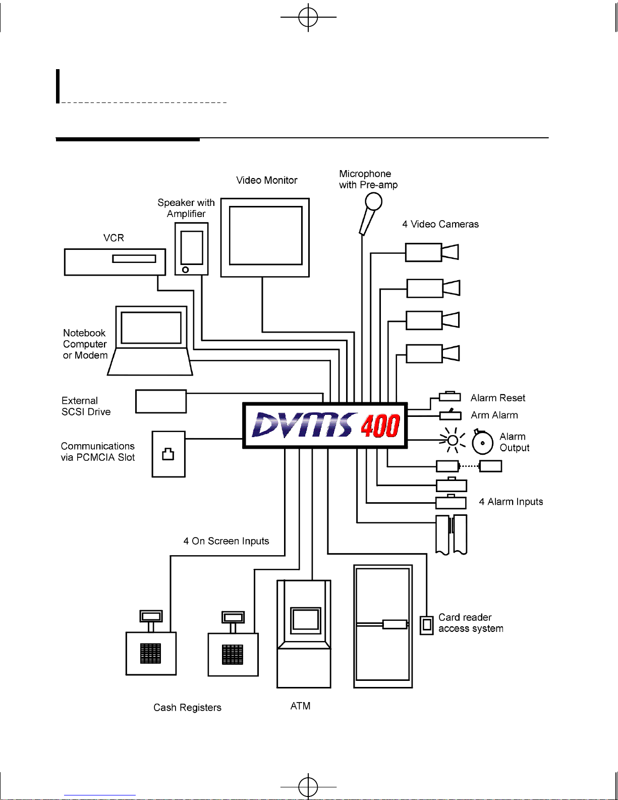
Sample Setup
4

Gyyr DVMS 400a.qxd 02/11/2000 3:45 PM Page 5
CHAPTER 1: INSTALLING THE DVMS
400 SYSTEM
Installation
Hooking Up Your Equipment
The Gyyr DVMS 400 is designed to work with a variety of other equipment.
In this section each type of equipment will be discussed in turn. Even the
most basic CCTV system will need at least one video camera, the cable
needed to connect the camera to the DVMS 400 unit and a video monitor to
use during the setup process. Your individual needs will determine exactly
which additional pieces of equipment are attached to your DVMS 400
system.
Video Cameras
There are 8 video inputs on the DVMS 400, 4 of which can be used at any
one time. Four of the video inputs are composite video inputs with loop
through connectors which use twist-lock BNC connectors. Four of the video
inputs are S-Video inputs which use 4-pin mini-DIN connectors. The output
from your 4 video cameras goes to these inputs. Each of the 4 inputs can
use monochrome or color and composite or S-Video input independent of
the other inputs. However, you cannot input both composite and S-Video
signals to the same input channel.
If you are using composite video inputs you may use the loop through
connectors to send the signal on to another video unit. This can be useful if
you want to view the video in more than one location. If you use the loop
through output you must set the termination switch located on the back of
the DVMS 400 unit. The switch block is labeled “On/Off 75ohms ”. When
using the loop through output, you must set that channel’s switch to “Off”.
In the “Off” position, the video is passed through (HiZ) without termination.
Any channel that does not use loop through must be set to “On”. This
terminates the video correctly at the DVMS 400. These settings affect the
quality of the visible video picture.
5

Gyyr DVMS 400a.qxd 02/11/2000 3:45 PM Page 6
Gyyr DVMS 400 User’s Guide
Video Monitor
There is a composite video monitor output which uses a twist-lock BNC
connector that you can use to hook up a composite video monitor. There is
also an S-Video monitor output which uses a mini-DIN connector which you
can use to hook up a monitor that supports S-Video. The video monitor
connected to either output should use the same broadcast standard (NTSC or
PAL) as your DVMS 400 unit. Both video monitor outputs may be used
simultaneously to provide two monitor capability.
Microphone
There is a mono audio input on the DVMS 400 which uses a standard RCA
connector. This can be used to input the sound signal from a microphone
with a pre-amp, such as the sound output from a camcorder.
Speaker
Text Insertion Ports
Alarm Inputs
There is a mono audio output which uses a standard RCA connector. This
allows you to listen to the live signal from your microphone or to hear the
audio signal during playback. This speaker will need its own amplifier and
volume control.
There are 4 Text Insertion ports that use DB-9P EIA-232 ASCII inputs. The
inputs for these ports may come from cash registers, ATM machines, a door
card reader access system, or any other source that outputs an asynchronous
ASCII output. The inputs can be set to display up to 40 characters per line
and up to 10 lines per camera on your output. Once text has been recorded
with the video image you can use the DVMS 400’s search program to search
for specific text.
There are 4 alarm inputs which respond to either normally open/closed contacts
(e.g., a hold-up button) or devices that use transistor to transistor logic (TTL)
open collector signals (e.g., a PIR detector). These inputs allow an alarm to be
triggered by a manually pressed button, an infra-red beam being interrupted, a
door contact being opened, or any other assigned signal. The DVMS 400’s
Setup Program is used to assign which type of signal is used by each alarm
input (see Alarm Inputs, page 41). These user defined alarm inputs are
separate from the alarms that are triggered automatically if a video signal is lost
or if an event is detected.
6

Gyyr DVMS 400a.qxd 02/11/2000 3:45 PM Page 7
Alarm Output
Arm Alarm and Alarm Reset
Installation
When the DVMS 400 detects an alarm the alarm output contact closes,
triggering any external alarm signals you have hooked up to this output (e.g.,
flashing lights, buzzers, bells).
The Arm Alarm input may be used to turn on or off the four Alarm Inputs.
You may choose not to use this input, in which case the Alarm Inputs will
always be on (unless a specific alarm has been turned off using the Setup
Program). If you do use the Arm Alarm input it will turn on or off all four
alarm inputs when activated. If you want to use the Arm Alarm input hook it
up to a normally open or normally closed switch (such as a clearly labeled
toggle switch). Use the Setup Program to select the appropriate settings (see
Alarm Inputs, page 41).
The Alarm Reset input can be used to reset or clear an alarm once it has
been activated. (The exact conditions needed to reset an alarm are discussed
on page 44, Event Recording, and on page 66, Event Handling.) If you want
to use the Alarm Reset input hook it up to switch that can be used to
momentarily change the contact status (such as an alarm reset button). If you
decide to use the Alarm Reset input an alarm will be considered active until
it is manually reset.
Remote Access Port (EIA-232)
The remote access port is a DB-9P, EIA-232 Async port which can be used
to hook up an external dial-up modem or a null modem cable to the DVMS
400.
This port is used when you want to use an external modem or a null modem
cable along with the DVMS 400’s Remote Access Software to control your
DVMS 400 from a PC. Hooking up a computer may be useful if you want
to collect data for analysis or if you want to access the Setup program.
Hooking up a modem also allows you to use a computer to access the
DVMS 400’s video monitoring, video playback, alarm reset and Setup
program from a remote site.
All remote access to the DVMS 400 is protected by password security.
7

Gyyr DVMS 400a.qxd 02/11/2000 3:45 PM Page 8
Gyyr DVMS 400 User’s Guide
SCSI Connector
A high density 50-pin SCSI connector has been provided to allow you to
increase your disk storage space with external SCSI-2 drives. The DVMS
400 can support up to 7 SCSI-2 devices, with a maximum of 2 internal SCSI
drives. Please consult your Gyyr Dealer if you want to add a drive to your
system.
PC Card Slot
The DVMS 400 has a PCMCIA PC Card slot provided for communication
needs using the small credit-card-sized PCMCIA cards used in some
notebook computers. This slot can be used for a PCMCIA modem or
ethernet card. Firmware upgrades can also be performed using PCMCIA
flash RAM cards.
Cables
The DVMS 400 uses common cable connectors for your hookup. Before
you begin to install the system you should consider the cables you will need.
The type and length of cable used for your video and audio inputs is an
important consideration as very long lengths can result in signal degradation.
Note that when you use the loop through connectors the total cable length to
the second video unit must be calculated from the camera, not just from the
first DVMS 400 unit.
8
Gyyr DVMS 400a.qxd 02/11/2000 3:45 PM Page 9
Using the Setup Program
Using the Cursor Controls
Installation
When you first power up your system you will need to enter a number of
settings to customize your DVMS 400 system. The DVMS 400’s Setup
program allows you to enter all the settings needed to customize your system
as well as providing you with access to video reports and alarm reports.
While you are using the Setup program you can control the cursor on the
screen with the cursor control buttons located on the right-hand side of the
DVMS 400’s front panel.
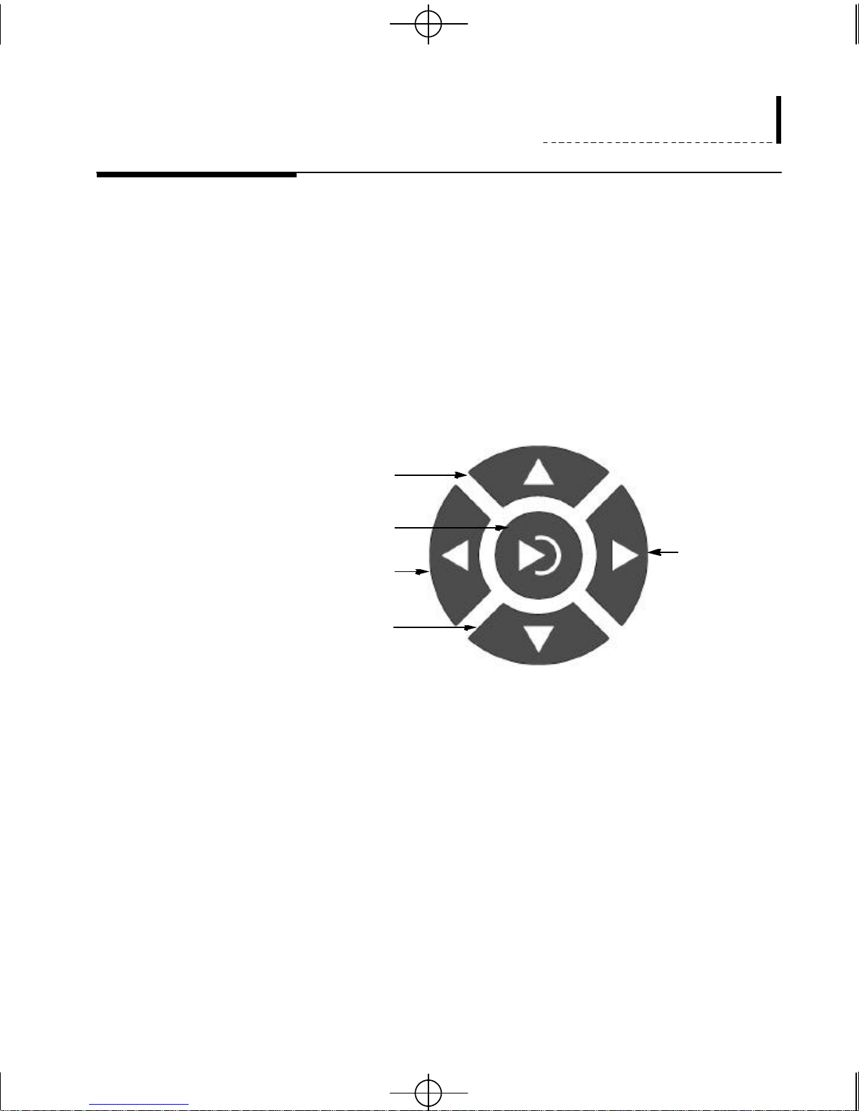
The cursor control buttons may be used to move to different parts of the
Up
Enter/Return
Right
Left
Down
screen, to scroll through a list, or to add text to a report. The part of the
screen that is active (and will be affected by the cursor buttons) will always
be outlined by a selection box.
When you want to change the text on screen (for example, the text used for a
camera title or report title) you can select the text box, use the right and left
cursor controls to move to different letters, and use the up and down cursor
controls to scroll through the letters. You can also use the jog knob (the
inner knob of the far right control knob) to scroll through the letters. You
can also use the Camera 1 button to insert a letter, the Camera 2 button to
delete a letter, and the Camera 3 button to open a Text Entry screen.
For all settings, press the Enter button to accept the change and to leave the
setting mode so that you can move to another area of the screen.
9
Gyyr DVMS 400a.qxd 02/11/2000 3:45 PM Page 10
Gyyr DVMS 400 User’s Guide
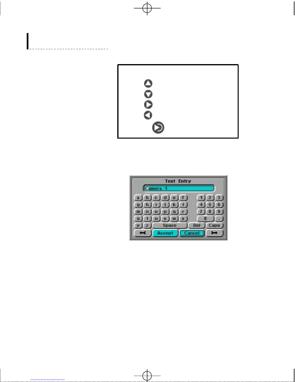
Controls
Up Camera 1: Insert text
Down Camera 2: Delete text
Right Camera 3: Text Entry
Left Jog knob: Advance
Enter/Return
Some setup screens have boxes where you can change the text (for example,
the title of a new Report, or the Camera Title) To change the text in these
boxes you must highlight the box and press enter. If you then press the
Camera 3 button a Text Entry screen will be opened.
The text you are changing is shown at the top of the Text Entry screen. The
individual letter you are currently changing is highlighted. To move between
letters use the arrow buttons at the bottom of the Text Entry screen. Use the
front panel’s cursor keys to move to the different buttons on the text entry
screen. To use a button move to it and then press the front panel’s enter key.
10
Gyyr DVMS 400a.qxd 02/11/2000 3:45 PM Page 11
Entering the Setup Program
Installation
When you enter the setup program the DVMS 400 stops recording. If the
unit is recording when you press the Setup button the DVMS 400 will warn
you that recording will stop. (If you have disabled all four User Names you
will not be asked for a password and you will not be warned that recording
will stop.)
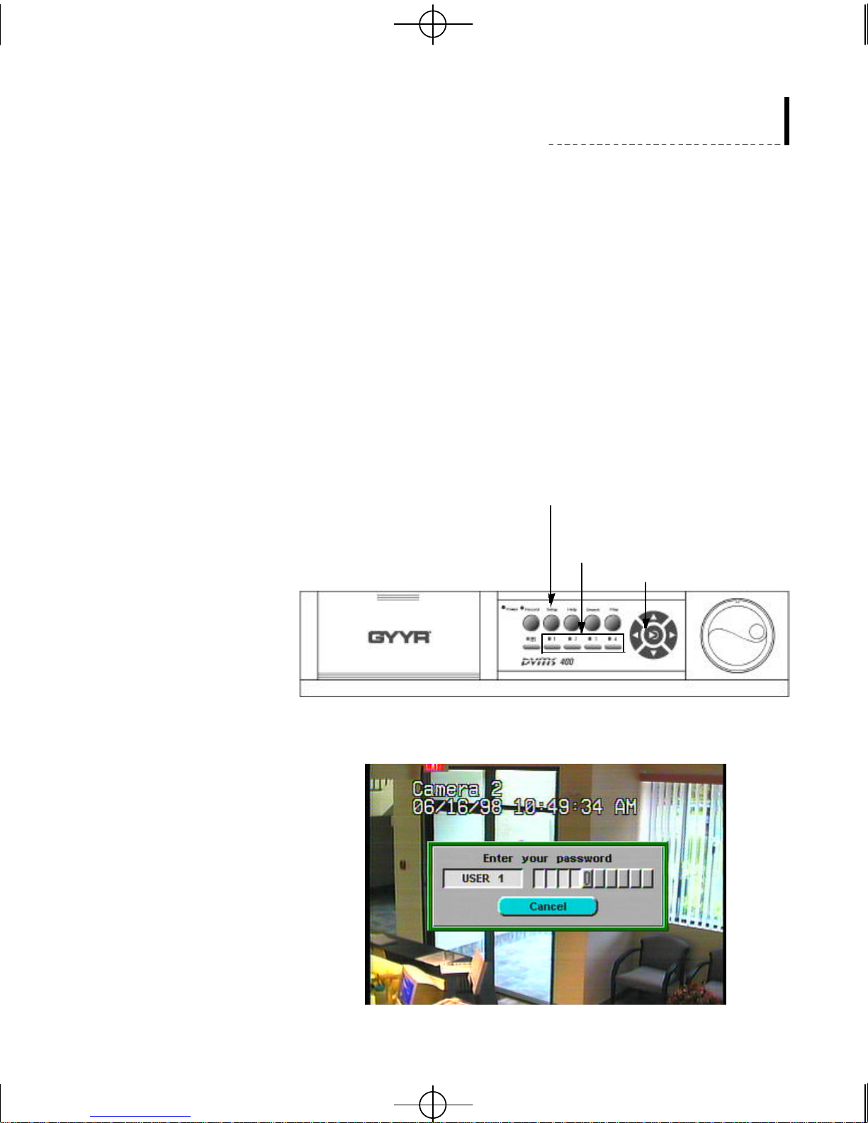
To start the Setup program press the Setup button on the front of the DVMS
400. You will be asked for your User Name and Password. Use a camera
button to select a User Name and then use the camera buttons to enter the
Password for that User Name. The default password is 1, 2, 3, 4. Press the
camera buttons in sequence and press the enter button. (Note that even if
you have changed your password to 0 keystrokes you still be asked for your
User Name and Password.)
To enter the setup program:
1. Press the setup button
2. Use the camera number buttons
to enter your user name and
password
3. Press enter.
As you enter each number in your password you will see the outlined square
move across the screen. If you do not want to enter the Setup program use
the down arrow to outline the on-screen Cancel button and press enter.
11
Gyyr DVMS 400a.qxd 02/11/2000 3:45 PM Page 12
Gyyr DVMS 400 User’s Guide
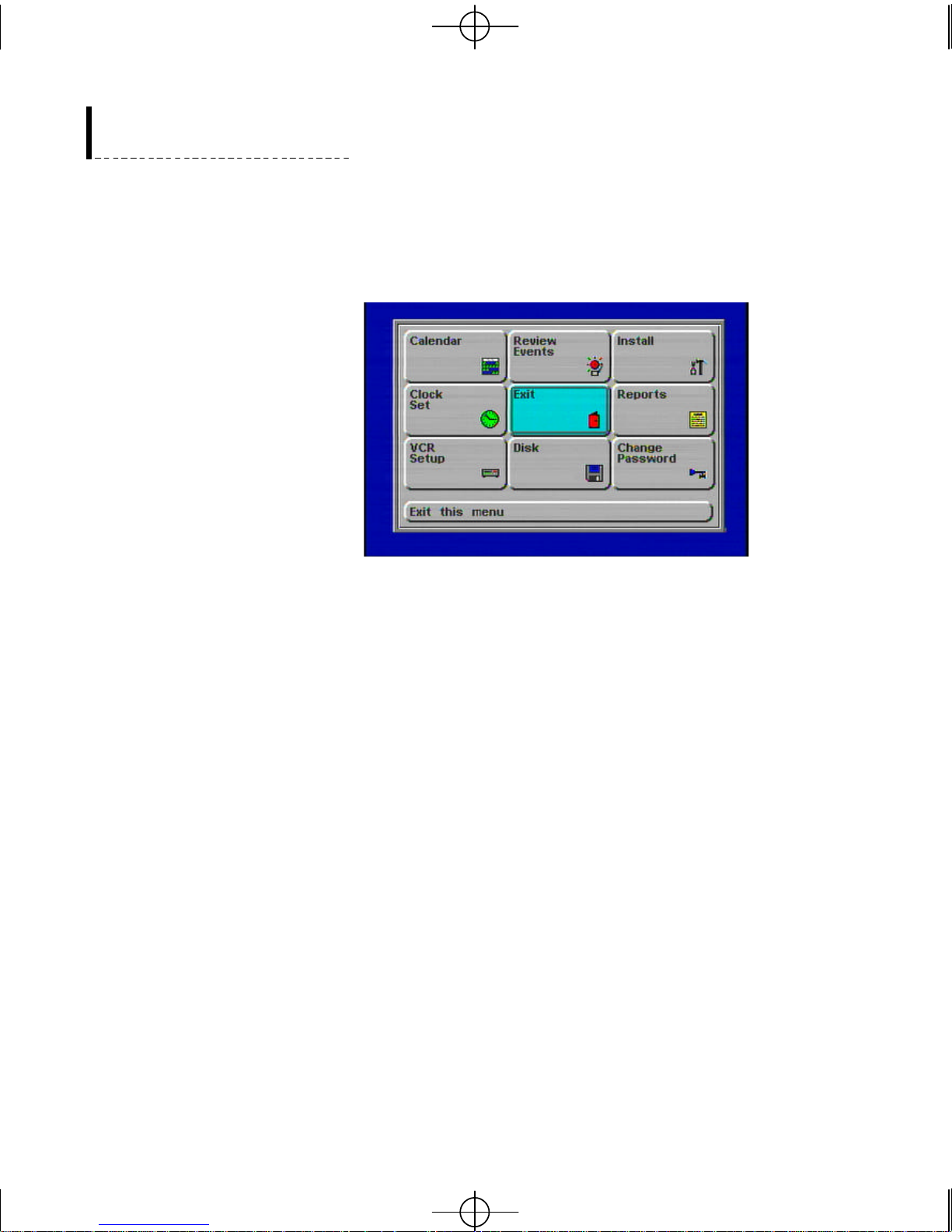
After entering the correct password the main Setup screen will be displayed.
The main setup screen is divided into squares, each with a different function.
You can move around this screen with the cursor keys and press enter to
select a function.
Exit Function
Change Password
There is an Exit button on both the Install screen and on the main Setup
screen. To exit the Install function and return to the main Setup screen
highlight the Exit button and press enter. To exit the Setup program entirely
highlight the Exit button on the main Setup screen and press enter.
The first thing you should do when setting up a new system is to change the
default password for each of the four user names. The four user names each
have their own password and user access levels. Change the default
password for each user name independently.
Use the cursor keys to move to the Change Password function and press
enter. Select a User Name by pressing one of the four camera buttons. Each
camera button is associated with one of the four User Names. The default
user names are USER 1, USER 2, USER 3 and USER 4. You may change
these names once you have changed your password.
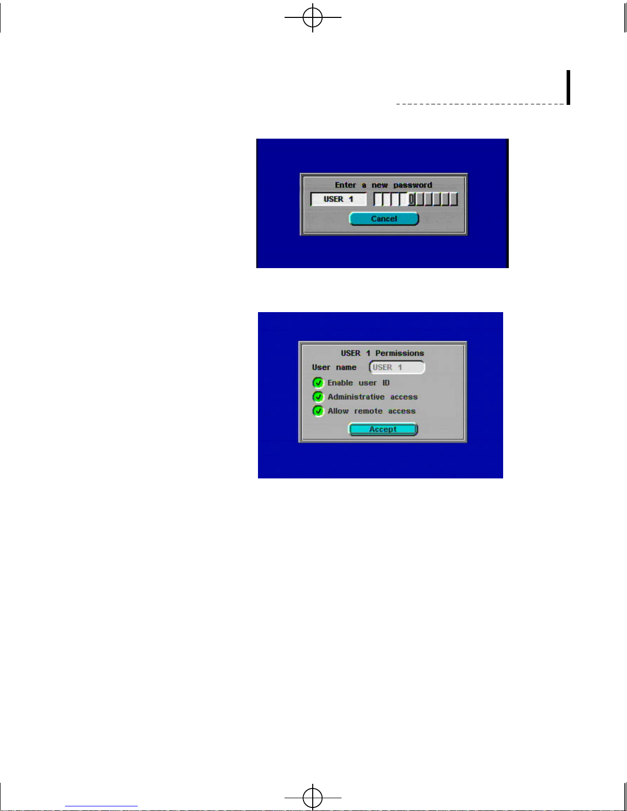
Enter a new password for the user name you have selected. Use the four
numbered camera buttons to enter your new password and press Enter. Once
you have entered your new password, you will be asked to confirm your
new password by entering your user name and new password again. Your
new password can be from 0 to 10 keystrokes long. If you do not want to
change your Password use the down arrow to outline the Cancel button and
press enter.
12
Gyyr DVMS 400a.qxd 02/11/2000 3:45 PM Page 13
Installation
Once you have successfully entered a new password (and confirmed it) you
will be shown the User Permissions for that User Name.
The User Name can be changed to any text desired. Use the up cursor
control to move up to the User Name box and press Enter. Use the cursor
controls to enter your new user name and press Enter. (See “Using the
Cursor Controls” on page 9.) Each User Name can also be given different
access permissions.
Enable User ID: If the Enable User ID is disabled, that User has no access
to the DVMS 400. If you disable all four Users then the password function
will be disabled when you use the unit locally (no User Name or Password
will be requested). At least one User Name must be enabled if you want to
use Remote Access.
Administrative Access: If Administrative Access is disabled, that User will
not be able to use any of the functions accessed by pressing the Setup key.
At least one user must have Administrative Access enabled.
Allow Remote Access: If the Remote Access is disabled, that User will not
be able to use the Remote Access Software.
13
Gyyr DVMS 400a.qxd 02/11/2000 3:45 PM Page 14
Gyyr DVMS 400 User’s Guide
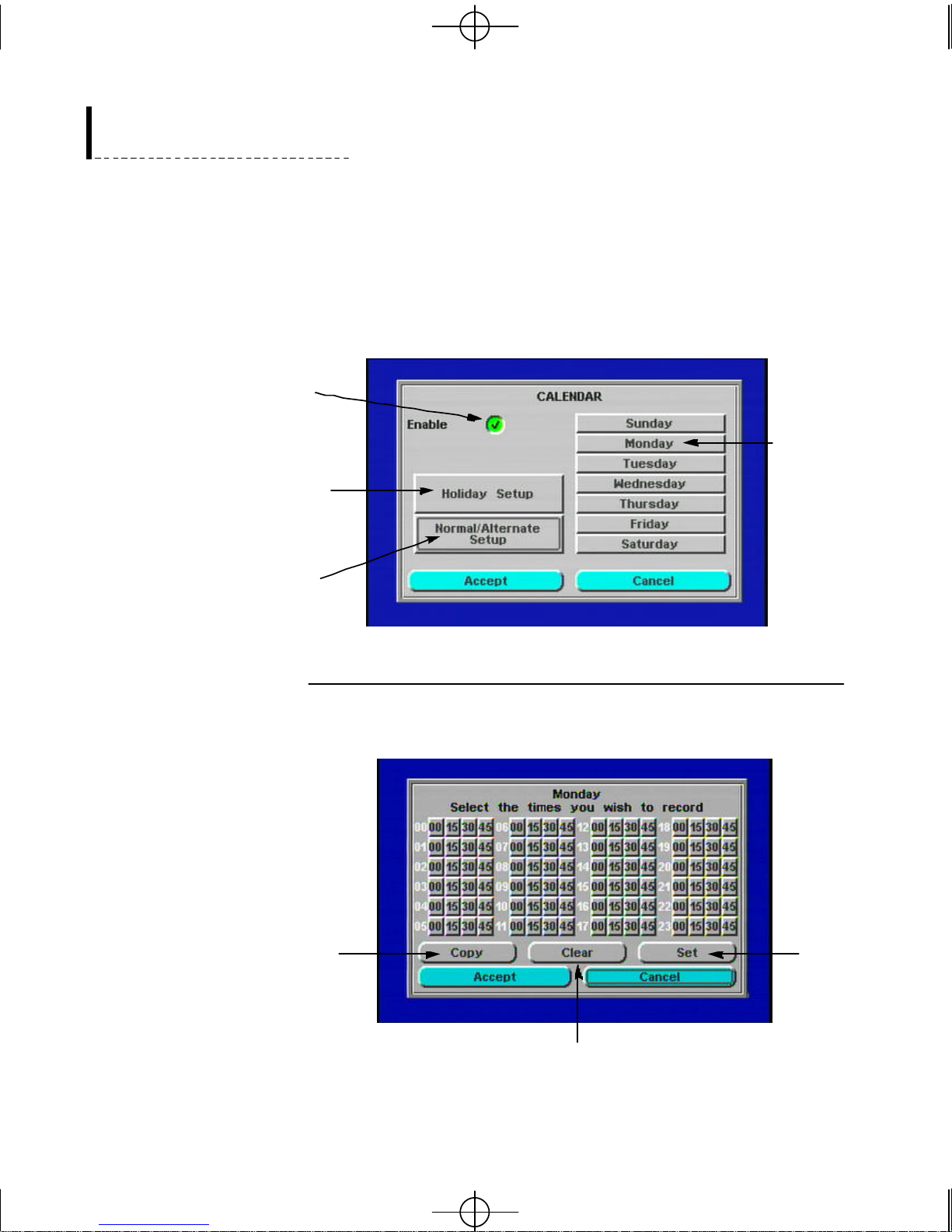
Calendar
The Calendar function allows you to set the recording times for each day of
the week, assign settings for up to ten holidays, and define alternate and
normal modes of operation. To access the Calendar screen select the
Calendar function from the main Setup screen and press enter. The picture
below shows the Calendar setup screen.
To use Calendar
functions, check the
Enable button.
To customize holiday
settings choose the
Holiday Setup button.
To set
recording
times, choose a
day button.
To define normal and
alternate modes of
operation choose the
Normal/Alternate Setup
button.
Setting Recording Times for a Day
To set recording times, choose a day button from the right side of the screen
and press enter. The recording time screen for the selected day appears.
To copy time settings
to other days of the
week choose Copy.
To set
record
times for
the entire
day choose
Set.
14
To clear all time settings on the
current screen choose Clear.
Gyyr DVMS 400a.qxd 02/11/2000 3:45 PM Page 15
Installation
Recording times are set in 15 minute increments for each hour using the 24
hour clock format. For example, to record from 9:00 am to 5:30 pm (9:00 to
17:30 in the 24 hour clock format) press all the buttons from row 09 up to
row 16; in row 17 press the 00 button and the 15 button. DVMS 400 records
for the day and times you have selected.
There are three additional features on each of the day recording times
screens:
w
The Copy button copies the settings you have selected in the active
screen to all other day screens.
w
The Clear button clears all selected times in the active screen.
w
The Set button selects all hours for the 24 hour day in the active screen.
When you have finished making your selections choose the Accept button at
the bottom right of the active screen and press Enter. DVMS 400 saves the
time settings for the day you have selected and returns you to the Calendar
setup screen.
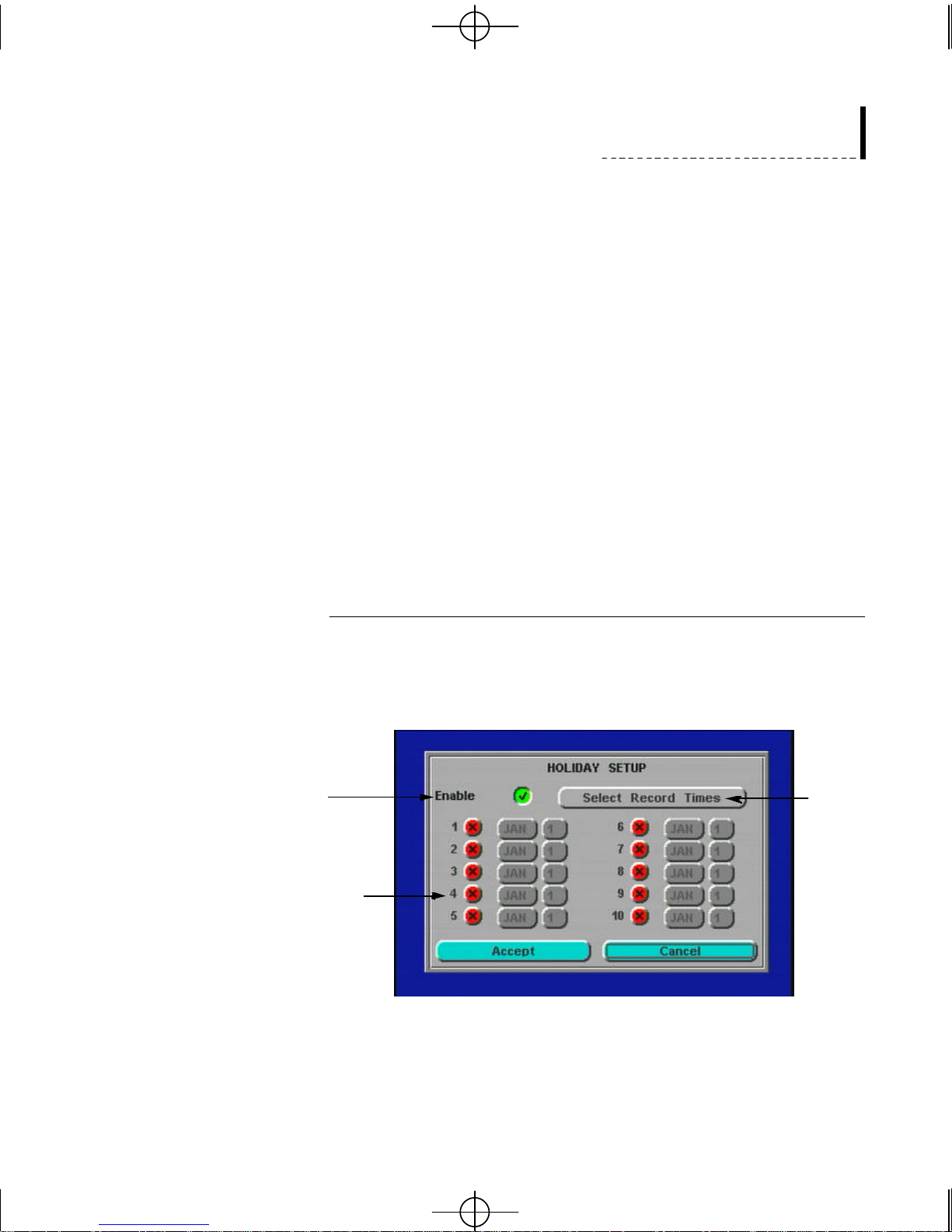
Using Holiday Setup
The Holiday Setup feature allows you to assign a custom setting for up to
ten holiday dates. From the Calendar screen select the Holiday Setup button
and press enter. The Holiday Setup screen appears. The picture below shows
the Holiday Setup screen with the Enable button checked.
To enable the Holiday
setup screen, check the
Enable button.
To define the date
for a holiday, check
a numbered button.
To enable the holiday setup screen choose the Enable button at the top right
of the screen and press Enter. The red X changes to a green check mark and
the numbered date settings are available.
To set holiday
record times,
choose the
Select Record
Times button
and press
enter.
15

Gyyr DVMS 400a.qxd 02/11/2000 3:45 PM Page 16
Gyyr DVMS 400 User’s Guide
To set the date for a holiday follow these steps:
1. Choose the numbered X beside a date box with the cursor keys and
2. Select the month box to the right of the numbered holiday button and
3. Select the month using either the cursor keys or the jog shuttle knob and
4. Repeat steps 2 and 3 for the day box to the right of the month box.
press Enter. The X changes to a check mark like the Enable button
described above.
press Enter. The month text changes from grey to black.
press Enter. The month display returns to grey with the selected month
displayed in the box.
When the correct day is displayed press Enter.
After the holiday date is set you must specify the recording times for the
Holiday Setup screen. Using the cursor control buttons choose Select Record
Times at the top right of the Holiday Setup screen and press Enter. The
screen changes to the Holidays screen. To set the Holiday record times
follow the instructions on page 14, Setting Recording Times for a Day.
NOTE: The Holiday time settings apply to all selected holidays. Times
cannot be set independently for each holiday.
Using Normal/Alternate Setup
DVMS 400’s Normal/Alternate Setup feature lets you split each day into 2
time periods, the Normal and Alternate times, and to assign each time period
its own recording settings. This allows you to create a secondary setup for
the way your system operates. This can help you in a number of different
ways. It can help you to conserve disk space during alternate hours. It can
also allow you to change recording modes to adapt to changing
circumstances.
For example, suppose you have an office that is open to the public from 9 to
5 on Mondays, and closed at other times. You can set the Normal recording
mode for Monday from 8:30 am to 5:30 pm. During Normal recording the
system uses time-lapse recording and records Alarm Events. On Mondays
the office closes at 5:00 pm, all employees leave the office by 5:30pm, and
system ends normal recording at 5:30 pm. After 5:30 pm the DVMS 400
enters its Alternate recording mode. When the system is in Alternate
recording mode the office is supposed to be unoccupied, so it may be set to
only record Motion Events.
16
Gyyr DVMS 400a.qxd 02/11/2000 3:45 PM Page 17
Installation
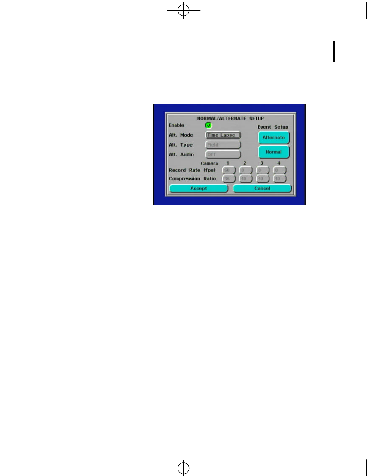
To show the Normal/Alternate Setup screen choose the Normal/Alternate
Setup button on the Calendar screen and press Enter. The picture below
shows the Normal/Alternate Setup screen with the Enable button checked.
The Alternate mode is defined through the Alt. Mode box. Choose the Alt.
Mode box using the cursor buttons and press Enter. The Alt. Mode box text
changes from grey to black. Use the cursor keys on the front panel to toggle
between Time-Lapse and Pre-Event Mode.
Setting Alternate Time-Lapse and Pre-Event Mode
After choosing an Alt. Mode (Time Lapse or Pre-Event) you can choose
either Frame or Field recording using the Alt. Type text box. Move to the
box and press Enter. Next, use the cursor keys to select either Field or Frame
and press Enter.
The Alternate Record Rate ( in fps) and Compression Ratio are set for each
camera using the boxes at the bottom of the screen. See Time-Lapse
Recording on page 42 for details on these settings.
NOTE: Only the Alternate time-lapse and pre-event video recording are
affected by the recording rate settings and compression ratio settings on the
Normal/Alternate Setup screen. For the Normal Time-Lapse and Pre-Event
settings use the Event Recording and Pre-Event Recording screens accessed
from the Main Setup Menu. See Pages 44-54 for details.
When the Alt. Mode Time-Lapse is selected the Alt. Audio option box
appears. To enable audio capture, select the the Alt. Audio box. Choose On
using the cursor keys and press Enter. Audio is now enabled for the Alt.
Mode Time-Lapse setup. To disable audio choose Off.
17
Gyyr DVMS 400a.qxd 02/11/2000 3:45 PM Page 18
Gyyr DVMS 400 User’s Guide
When the Alt Mode box is set to Pre-event, the Alt. Audio box changes to an
Alt. Length box. You can use this to set the length of the alternate pre-event
recording. Use the cursor keys choose the min box to the right of the Alt.
Length caption and press Enter. Using the cursor keys or the shuttle knob,
you can select from 0 to 59 minutes. You can set seconds the same way in
the sec box to the right of the min box. When you are finished selecting the
alternate pre-event recording length, press enter. DVMS 400 saves the
alternate pre-event length.
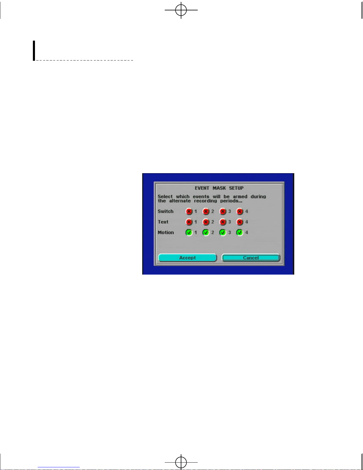
After the Alt. Mode and the Alt. Type have been selected, set the events you
want to record during Alternate recording. Choose the Alternate button and
press Enter. The screen changes to the Event Mask Setup screen.
18
The Event Mask Setup screen displays four selection boxes for each of the
three types of event recording: Switch (Alarm), Text, and Motion. When a
selection box is checked the event recording for that type of input is enabled.
For example, when all four of the selection boxes in the Motion category are
checked, as in the above picture, four motion detection inputs are enabled
during the Alternate recording periods.
To save the event masks for the alternate recording periods choose the
Accept button and press enter. DVMS 400 returns to the Normal/Alternate
Setup screen.
To set the Event Mask screen for the Normal recording periods select the
Normal button below the Alternate button on the Normal/Alternate Setup
screen and press Enter. DVMS 400 shows the Event Mask Setup screen for
the Normal recording periods.
Gyyr DVMS 400a.qxd 02/11/2000 3:45 PM Page 19
Installation
For the Normal Event Mask Setup repeat the procedure for setting up the
Alternate Event Mask Setup. When the normal Event Mask Setup screen is
complete choose the Accept button in the lower left of the screen and press
Enter. DVMS 400 returns to the Normal/Alternate setup screen.
NOTE: When the Calendar function is enabled the Normal Event Mask
Setup over-rides individual event settings. For Example, if you have enabled
Motion Detection 1 and you have enable the Calendar function’s
Normal/Alternate Mode you must enable Motion 1 in the Normal Event
Mask Setup for it to be enabled during Normal Mode recording.
To save the Normal/Alternate setup choose the Accept button on the lower
left of the screen and press Enter. DVMS 400 saves all of the settings you
have selected. Your alternate settings are now enabled. The screen returns to
the Calendar setup screen.
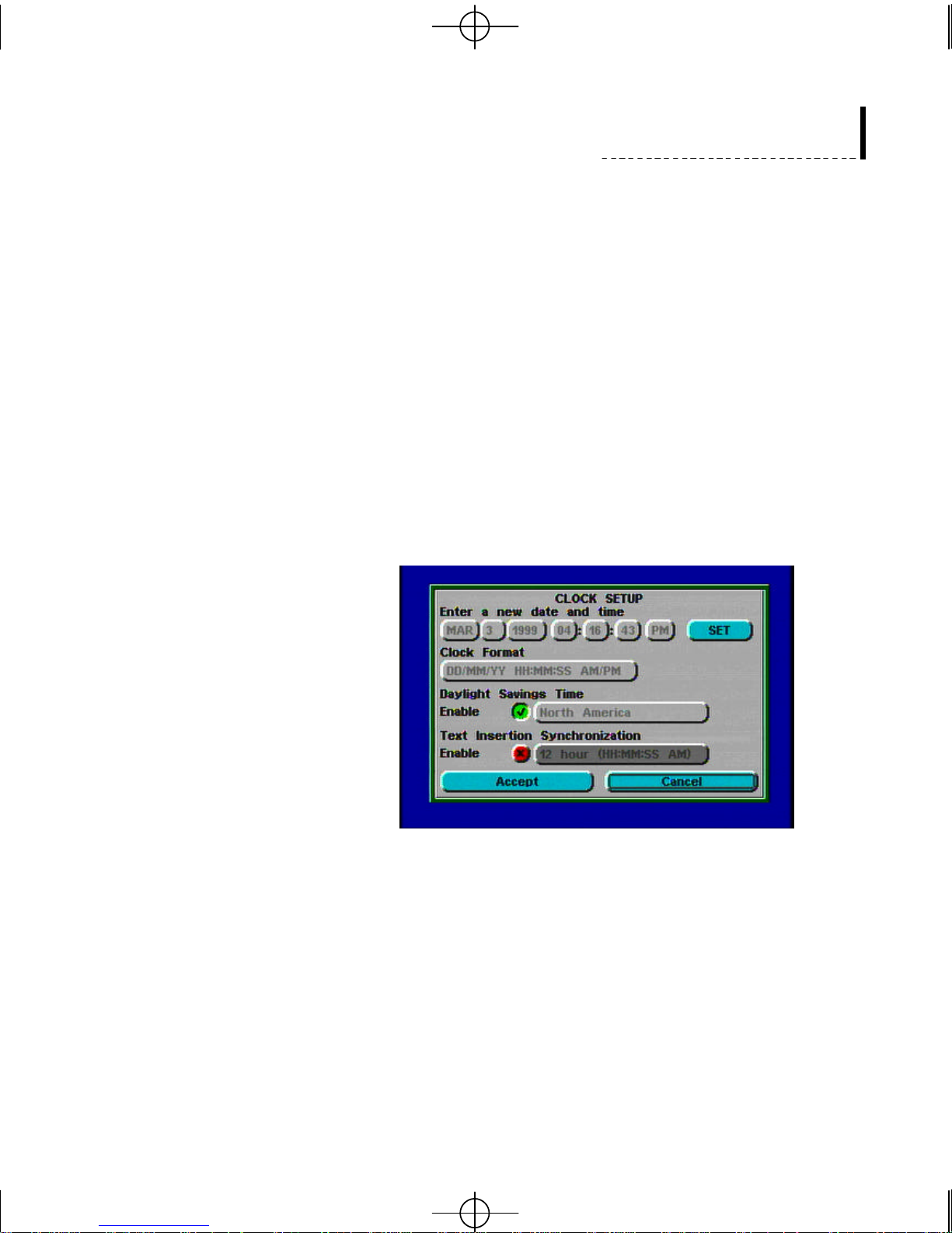
Clock Se t
To change the current date and time first select the Clock Format. The date
format choices are month/day/year or day/month/year. The clock format
choices are the 24 hour clock format (for example 14:30 rather than 2:30 pm)
or the 12 hour clock format (using AM and PM). To change the date and time
move to the month, day, year and time using the cursor controls. Use the Enter
button to select an item and then use the up and down cursor controls to change
the value. You can also use the jog knob (the large inner knob found on the
right of the front panel) to change the value. Press Enter to accept a value.
When you have finished entering the correct date and time you must press the
Set button to reset the DVMS 400’s clock.
You can also enable Daylight Savings Time. If you enable this option you
will also need to select the correct geographic area, as Daylight Savings
19
Gyyr DVMS 400a.qxd 02/11/2000 3:45 PM Page 20
Gyyr DVMS 400 User’s Guide
Time varies from one region to another. If enabled, the DVMS 400 will
automatically adjust itself by one hour in the spring and one hour in the fall.
Please note, if the DVMS 400 is being used by a user at the time of the
Daylight Savings Time change (e.g., camera buttons are being pressed, the
Setup program is being used, etc.) the time change will not take effect. Also,
if the DVMS 400 is recording an event at the time of the Daylight Savings
Time change, recording will temporarily stop, the time will be changed, and
then the recording will begin again.
Instead of setting the current time yourself you may enable the “Text
Insertion Synchronization” function and the date and time used by your
DVMS 400 will be set to the date and time used by the devices connected to
your Text Insertion Input ports. If more than one input contains clock
information, it is recommended that you do not use this option and that you
set the current date and time yourself.
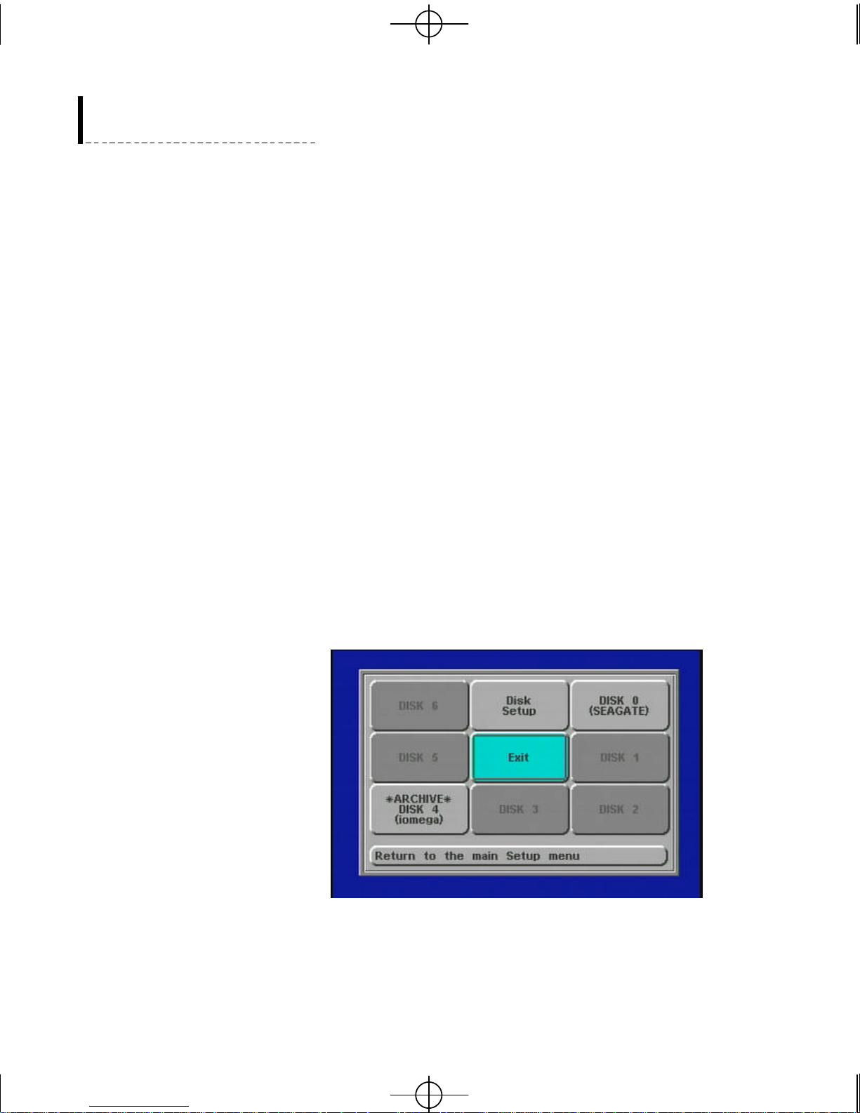
Disk
The Disk function allows you to setup, configure, and check the status of the
disk drives used to store your digital video. When a disk is installed and
operating in your DVMS 400 a button will be highlighted on the Disk Setup
screen. The number of additional buttons you see enabled on the Disk screen
will depend on the number of additional drives you have installed in your
system. If you have purchased optional removable media drives you will
also be able to check their status using the Disk status buttons.
Before you use your DVMS 400 you should check the Disk Setup screen. It
allows you to select and control the way data will be saved to your disk
drives.
20
Gyyr DVMS 400a.qxd 02/11/2000 3:45 PM Page 21
Installation
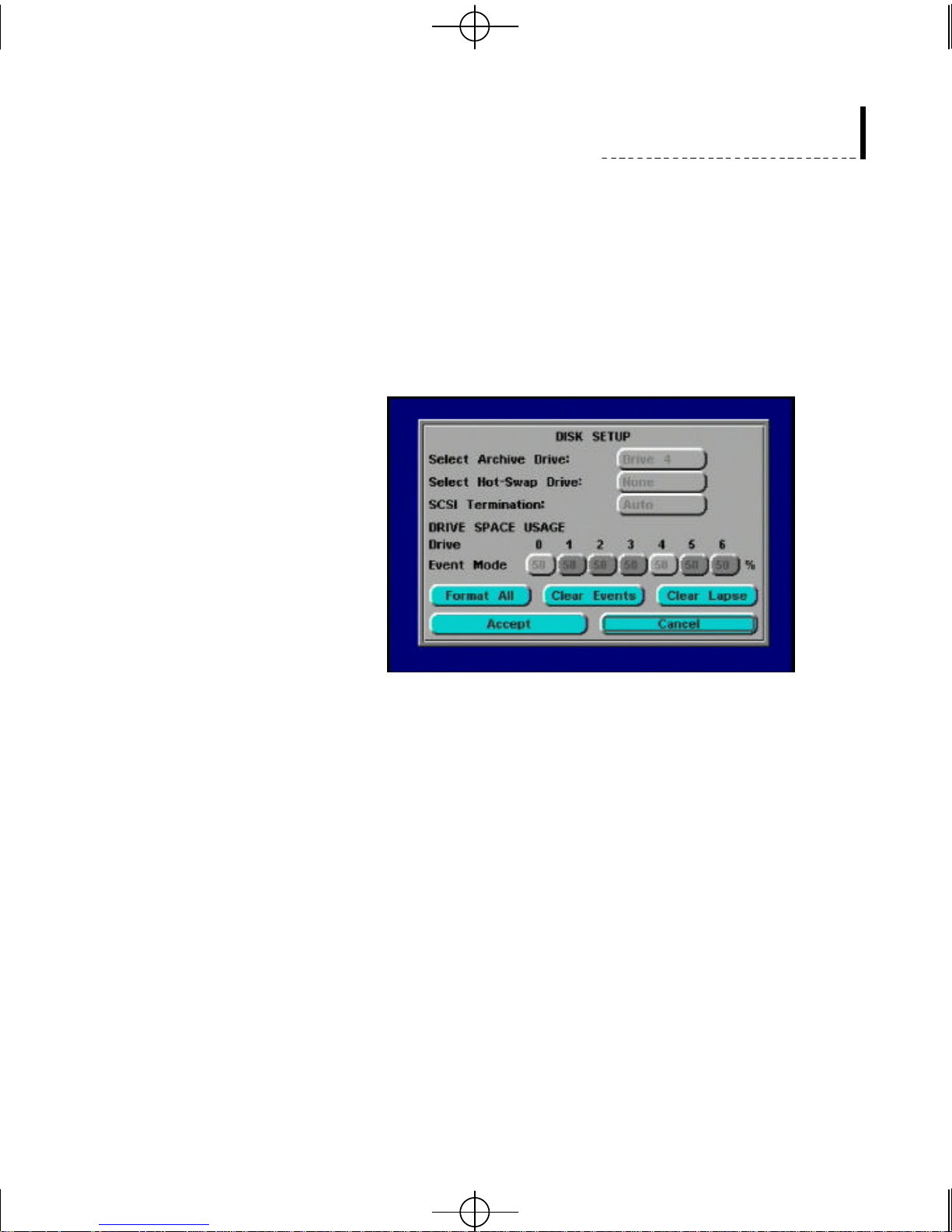
On the Disk Setup screen you will need to select the percent of the regular
drive space that you want to be used for Event mode recording (video
recording triggered by events) for each drive you have installed. The rest of
the space will automatically be used for time lapse recording.
NOTE:If you want to change the % used for Event Mode all the video clips
will have to be cleared from the drive before the new setting can be applied.
Make sure you set the % you want to use for Event Mode before you begin
recording video.
There is a box at the top of the Disk Setup screen to allow you to select an
archive drive. If a drive is not selected, all of your drives, including your
removable disks, will be used for event or time-lapse video clips. Removable
disks are not as robust as fixed drives, and they may fail if they spin
continuously for months. Therefore, removable disks should normally be
used for archiving purposes only.
The SCSITermination box allows you to set your drive’s on-board
termination.The Auto option is recommended. If you are familiar with SCSI
termination, you can set the option to On or Off depending on what other
devices are connected to the DVMS 400.
The Disk Setup screen allows you to clear all video clips from your drives
using the Format All button. The Clear Events button clears only event video
clips and the Clear Lapse button clears only Time-Lapse video clips.
DVMS 400 allows you to specify a single drive as a Hot-Swap drive. A HotSwap drive can be removed and replaced with another drive while the unit is
powered on. This allows easy archiving of large amounts of data. For
example a weekly archive could be managed using seven large drives,
replaced on a daily basis and rotated weekly using the Hot-Swap function.
21
Gyyr DVMS 400a.qxd 02/11/2000 3:45 PM Page 22
Gyyr DVMS 400 User’s Guide
To setup the Hot Swap feature use the Disk Setup menu to select a drive
number as your Hot-Swap drive and press Enter.
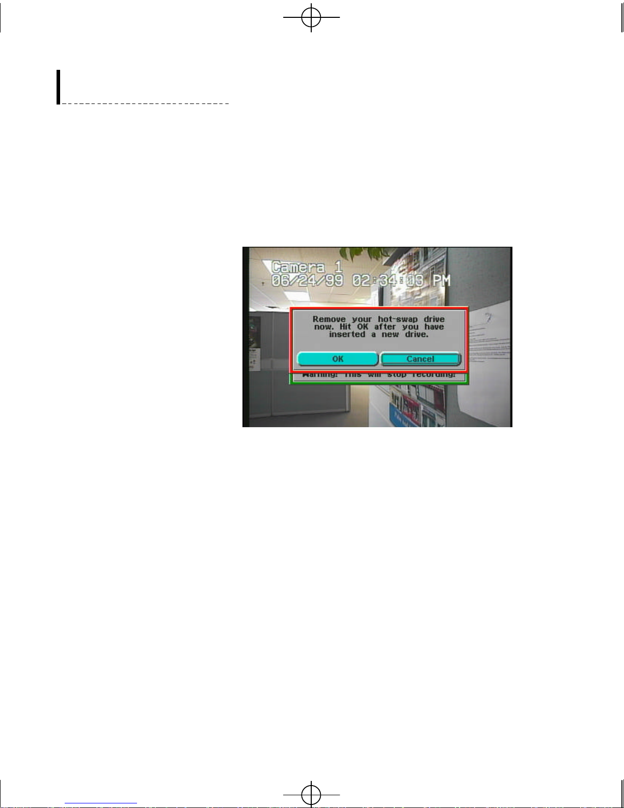
To use the Hot-Swap feature exit the Main Setup screen. Press the Help
button on the front panel of the DVMS 400. The User Name dialog box
appears. Enter your User Name and Password and press Enter. A text box
appears prompting you to remove your Hot-Swap drive. Follow the
Instructions on the screen to complete your Hot-Swap.
NOTE: All drives being swapped into the unit must have the same SCSI id.
To avoid possible data loss, it is recommended that you use only one regular
disk on your system to record when using the Hot-Swap feature. A second
drive for archiving is allowable when using Hot-Swap. When the archive
drive is designated as the Hot-Swap drive, the single disk restriction does not
apply.
22
 Loading...