

GYS TRIMIG 200-4S, TRIMIG 250-4S DV 230/400V, TRIMIG 300-4S, TRIMIG 300 G, TRIMIG 350 G DV 230/400V User guide [ml]
...
FR
4-6 / 21-32
TRIMIG 200-4S
TRIMIG 250-4S DV 230/400V
EN
DE
ES
RU
75559 - V8 - 22/06/2015
7-9 / 21-32
10-13 / 21-32
14-16 / 21-32
17-20 / 21-32
TRIMIG 300-4S & 300 G
TRIMIG 350 G DV 230/400V
TRIMIG 350-4S DUO DV 230/400V
www.gys.fr
I
II
TRIMIG
Trimig 200-4S/250-4S DV/300-4S
12
rimig 300 g/350-4S DUO DV/350 g DV
T
12
14
15
TRIMIG 300 G / 350 G
18
10
13
7
11
9
5
6
3
2
1
4
16
17
III
A
8
B
2
IV
Trimig
250/300/350
TRIMIG
1
2 3
4
8
5 6 7
9
V
Trimig 200
1
1
Trimig 250/300/350
4
4
2
2
VI
5
3
Ar CO2 CO2Ar
1
—
2
—
3
3
5
6
6
10
—
12
Acier / SteelAlu
Wire
ø 0,8ø 1,0ø 1,2
1
—
3
2
3
3
4
—
3
—
3
1
5
4
7
6
—
10
12
mm
1
1 mm
1,5 mm
2 mm
4 mm
6 mm
10 mm / +
Acier / Steel
Inox / Stainless
ø 0,8ø 1,0ø 1,2ø 1,0ø 1,2
1
2
3
6
—
—
3
—
—
3
—
3
3
6
6
7
8
—
10
5
3
TRIMIG
DESCRIPTION
Merci de votre choix ! An de tirer le maximum de satisfaction de votre poste, veuillez lire avec attention ce qui suit :
Les Trimig sont des postes de soudure semi-automatique « synergic » sur roues, ventilés pour le soudage (MIG ou
MAG). Ils sont recommandés pour le soudage des aciers, des inox, des aluminiums. Leur réglage est simple et rapide
grâce à leur fonction « vitesse de l synergique ». Ils fonctionnent sur une alimentation 400V triphasée ou 230V triphasée pour les modèles DV.
ALIMENTATION ÉLECTRIQUE
Le courant effectif absorbé (I1eff) pour les conditions d'utilisation maximales est indiqué sur l'appareil. Vérier que
l'alimentation et ses protections (fusible et/ou disjoncteur) sont compatibles avec le courant nécessaire en utilisation.
L'appareil doit être placé de façon telle que la che de prise de courant soit accessible. Ne pas utiliser de rallonge ayant
une section inférieure à 4 mm². Ces appareils sont livrés avec une prise 16A de type CEE 7/7. Les Trimig doivent être
reliés à une prise 400V 3Ph. AVEC terre protégée par un disjoncteur 16A et un différentiel 30mA.
Alimentation 230V triphasée du Trimig 250-4S DV, 350 G DV et 350-4S DUO DV
ATTENTION : ces appareils sont pré-monté en usine en 400V triphasée. Si votre installation électrique est en 230V
triphasée, veuillez modier le branchement de la plaque à bornes à l’intérieur du poste. Cette manipulation doit être
effectuée par une personne compétente. Pour ce faire se référer au schéma de branchement 230V situé à l’intérieur du
poste. L’alimentation électrique doit être protégée par un disjoncteur 16A et 25A pour les 350 et un différentiel 30mA.
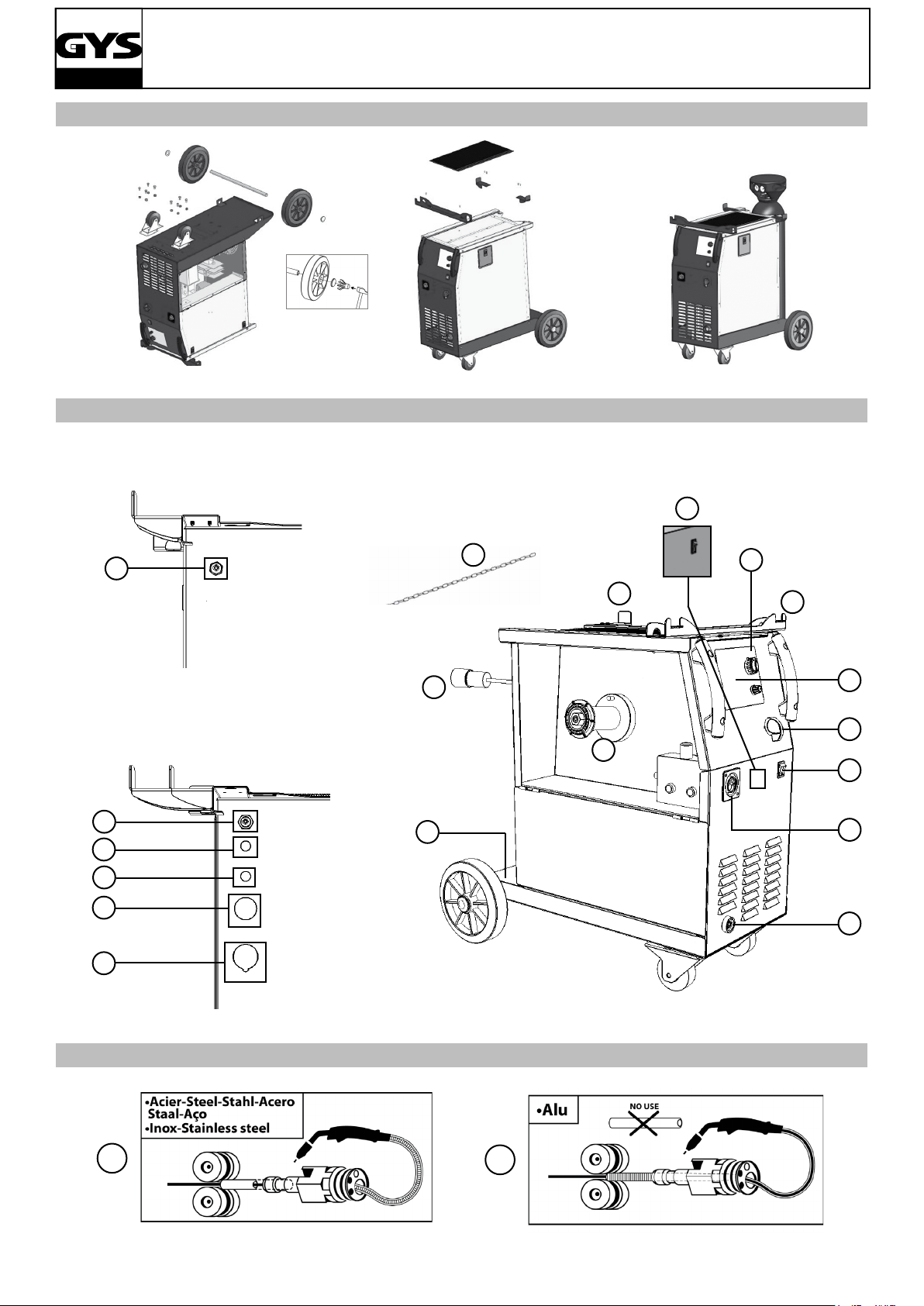
DESCRIPTION DU POSTE (FIG-II)
FR
1- Interrupteur marche – arrêt
2- Commutateur de réglage de tension
3- Clavier de réglages des paramètres de soudage (mode
manuel ou automatique).
4- Raccord torche au standard européen.
5- Voyant de protection thermique sur le clavier de commande : signale une coupure thermique lorsque l’appareil est utilisé de façon intensive (coupure de plusieurs
minutes).
6- Support torches avant
7- Câble d’alimentation 8- Sortie pince de masse.
9- Support bouteille (maxi une bouteille de 10m3).
10- Chaine de xation pour bouteille. Attention : bien
SOUDAGE SEMI-AUTOMATIQUE EN ACIER/INOX (MODE MAG) (FIG-III)
Le Trimig 200-4S peut souder du l acier et inox de 0,6/0,8 et 1. (III-A) L’appareil est livré d’origine pour fonctionner
avec du l Ø 1,0 mm en acier (tube contact Ø 1.0, galets Ø 0,8/1,0). Lorsque vous utilisez du l de diamètre inférieur ;
il convient de changer le tube contact. Le galet du moto-dévidoir est un galet réversible. Le positionner de telle façon à
lire le chiffre souhaité sur le anc visible du galet. Le Trimig 250-4S DV 230-400V peut souder du l acier et inox de 0,8/1
et 1,2. Il est livré d’origine pour fonctionner avec du l Ø 1,0 mm en acier( galets Ø 0,8/1) Les Trimig 300-4S, 300 G,
350-4S DUO DV et 350 G DV peuvent souder du l acier et inox de 0,8/1 et 1,2. Ils sont livrés d’origine pour fonctionner
avec du l Ø 1 mm en acier (galet Ø 1/1,2) L’utilisation en acier ou inox nécessite un gaz spécique au soudage argon
+ CO2 (Ar + CO2 ). La proportion de CO2 varie selon l’utilisation. Pour le choix du gaz, demander conseil à un distributeur de gaz. Le débit de gaz en acier se situe entre 10 et 20 L/min selon l’environnement et l’expérience du soudeur.
xer la bouteille cf. IV-1
11- Support bobine Ø 200/300 mm.
12- Entrée gaz 1 (350-4S DUO DV)
13- Support cables arrière. (200/250/300 un seul support
à gauche ou à droite. 300G/350DUO/350G 2 supports)
14- Entrée gaz 2 du dévidoir séparé
(300G/350DUO/350G)
15- Sortie gaz 2 du dévidoir séparé
16- Connecteur de commande du dévidoir séparé
17- Connecteur de puissance du dévidoir séparé
18- Interrupteur de sélection de potentiomètre (uniquement sur les 300G et 350 G DV)
SOUDAGE SEMI-AUTOMATIQUE ALUMINIUM (FIG-III)
Le Trimig 200-4S peut souder du l aluminium de 0,8 et 1 mm. (III-B) Les Trimig 250, 300 et 350 peuvent souder du
l aluminium de 1 mm et 1,2 mm. (III-B) Pour souder l’aluminium, il faut utiliser un gaz neutre: argon pur (Ar). Pour le
choix du gaz, demander conseil à un distributeur de gaz. Le débit du gaz se situe entre 15 et 25 L/min selon l’environnement et l’expérience du soudeur. Ci-dessous les différences entre l’utilisation soudage acier et soudage aluminium :
• La pression des galets presseurs du moto-dévidoir sur le l : mettre un minimum de pression an de ne pas écraser
le l.
• Tube capillaire : retirer le tube capillaire avant de connecter la torche aluminium avec une gaine en téon.
• Torche : utiliser une torche spéciale aluminium. Cette torche possède une gaine téon an de réduire les frottements.
• NE PAS couper la Gaine au bord du raccord ! cette gaine sert à guider le l à partir des galets. (III-B)
• Tube contact : utiliser un tube contact SPECIAL aluminium correspondant au diamètre du l.
4
TRIMIG
SOUDAGE SEMI-AUTOMATIQUE DES ACIERS À HAUTE LIMITE ÉLASTIQUE
Le Trimig 200-4S peut soudobraser les tôles à haute limite élastique avec un l en cuprosilicium (CuSi3) ou en cuproaluminium (CuAl8) (ø 0,8 et ø 0,1 mm). Le soudeur doit utiliser un gaz neutre: argon pur (Ar). Pour le choix du gaz,
demander conseil à un distributeur de gaz. Le débit du gaz se situe entre 15 et 25 L/min.
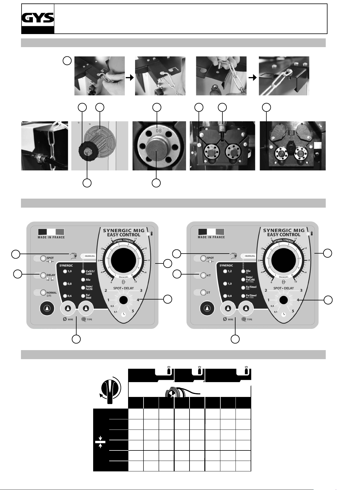
PROCÉDURE DE MONTAGE DES BOBINES ET DES TORCHES (FIG-IV)
Ouvrir la trappe du poste.
• Positionner la bobine en tenant compte de l’ergot d’entrainement (3) du support bobine. Pour monter une bobine de
200mm, installer au préalable un adaptateur sur le support (ref. 042889).
• Régler le frein de la bobine (4) pour éviter lors de l’arrêt de la soudure que l’inertie de la bobine n’emmêle le l. De
manière générale, ne pas serrer trop fort ! Serrer ensuite fermement la vis de maintien (2).
• Les galets moteur (8) sont des galets double gorge (Ø 0,8/ Ø 1 ou Ø 1/ Ø 1,2). L’indication qu’on lit sur le galet est
celle que l’on utilise. Pour un l de Ø 1 mm, utiliser la gorge de Ø 1. • Pour la première mise en service :
- désserrer la vis de xation du guide l (5)
- placer les galets, bien serrer leur vis de maintien (9).
- puis positionner le guide l (7) au plus près du galet mais sans contact avec ce dernier, puis resserrer la vis de xation.
• Pour régler la molette des galets presseurs (6), procéder comme suit : desserrer au maximum, actionner le moteur en
appuyant sur la gâchette de la torche, serrer la molette tout en restant appuyé sur la gâchette. Plier le l en sortie de la
buse. Mettre un doigt sur le l plié pour l’empécher d’avancer. Le réglage du serrage est bon lorsque les galets patinent
sur le l même si le l est bloqué en bout de torche.
• Réglage courant de la molette des galets (6): graduation sur 3-4 pour l’acier et graduation sur 2-3 pour l’aluminium.
FR
CHOIX DES BOBINES
Congurations possibles:
Type l Torche Gaz
acier
inox
Alu
AG5
*prévoir gaine téon/tube contact spécial alu. Ôter le tube capillaire
RACCORDEMENT GAZ
Visser le manodétendeur sur la bouteille de gaz si besoin est, puis connecter le tuyau fourni au raccord gaz. Pour éviter
toute fuite de gaz, utiliser les colliers fournis dans la boîte d’accessoires. Assurer le bon maintient de la bouteille de gaz
en respectant la xation de la chaine cf. IV-1
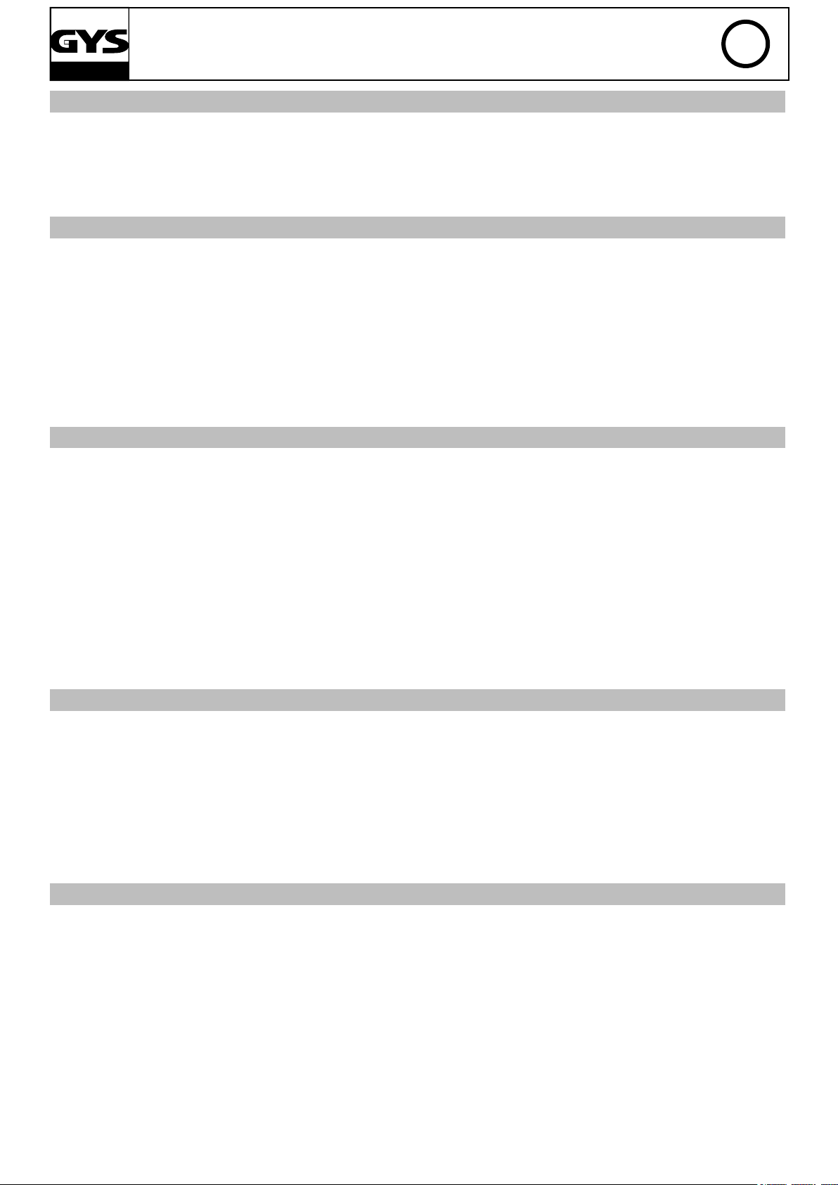
CLAVIER DE COMMANDE (FIG-V)
Choix du mode de soudage (2)
- NORMAL (2T) : soudage standard 2 temps
- NORMAL (4T) : soudage standard 4 temps
- DELAY : fonction « point de chainette », avec réglage
de l’intermittence de point
- SPOT : fonction bouchonnage /spot, Avec réglage du
diamètre du point Réglage de la vitesse l (4) Potentiomètre d’ajustage de la vitesse du l. La vitesse varie de 1
à 15 m/minute.
Potentiomètre de réglage SPOT/DELAY (5)
Ø 300 x
Ø 200 x
Ø 200 x
Ø 300 x*
Ø 200 x*
argon
+
CO2
Argon pur
Mode Manual (1)
En mode manuel, la vitesse de dévidage du l est déterminée par l’utilisateur en ajustant le potentiomètre (4).
Mode Synergic (3)
Positionner le potentiomètre (4) au milieu de la zone
«OPTIMAL SYNERGIC »
Dans ce mode le poste détermine la vitesse de l optimale à partir de 3 paramètres :
- Tension
- Diamètre du l
- Nature du l Il est possible d’ajuster la vitesse du l +
/ -.
5
TRIMIG
MODE "MANUEL" (FIG-V)
Pour régler votre poste procéder comme suit :
• Choisissez la tension de soudage à l’aide du commutateur 7-10-12 ou 2*7 positions (selon le poste).
- exemple :
Pour souder de l’acier 1 mm avec un l de diamètre ø 0,8 mm mettez le commutateur sur la position 1
• Ajustez la vitesse du l à l’aide du potentiomètre (4).
Conseils:
L’ajustement de la vitesse du l se fait souvent « au bruit » : l’arc doit être stable et avoir très peu de crépitement.
Si la vitesse est trop faible, l’arc n’est pas continu. Si la vitesse est trop élevée, l’arc crépite et le l a tendance à
repousser la torche.
MODE "SYNERGIC" (FIG-V)
Grâce à cette fonction, plus besoin de régler la vitesse l.
• Positionner le potentiomètre (4) vitesse l au milieu de la zone « Optimal synergic » • Sélectionner :
- La nature du l (3)
- le diamètre du l (3)
- La puissance (commutateur en face avant)
Pour sélectionner la position adéquate en fonction de l’épaisseur à souder se référer au tableau « mode synergic » de
la page en vis à vis. A partir de cette combinaison de paramètres, cet appareil détermine la vitesse de l optimale et le
poste est prêt à souder. Il est ensuite possible d’ajuster la vitesse l si nécessaire en + ou en – grâce au potentiomètre
(4). Une mémorisation des dernières congurations de soudage est effectuée et réactivée à chaque mise en route du
poste ou à chaque appui sur la gâchette d’une des torches du générateur ou du dévidoir séparé (diamètre l, nature
l, mode).
FR
CONSEIL ET PROTECTION THERMIQUE
• L’appareil ne doit pas être élingué par ses poignées, ses supports torches ou son plateau supérieur mais par le dessous
du poste. La bouteille ne doit pas être xée sur le poste durant cette opération.
• Respecter les règles classiques du soudage.
• Laisser les ouïes de l'appareil libres pour l’entrée et la sortie d’air.
• Laisser l’appareil branché après soudage pour permettre le refroidissement.
• Protection thermique : le voyant s’allume et la durée de refroidissement est de quelques minutes en fonction de la
température ambiante.
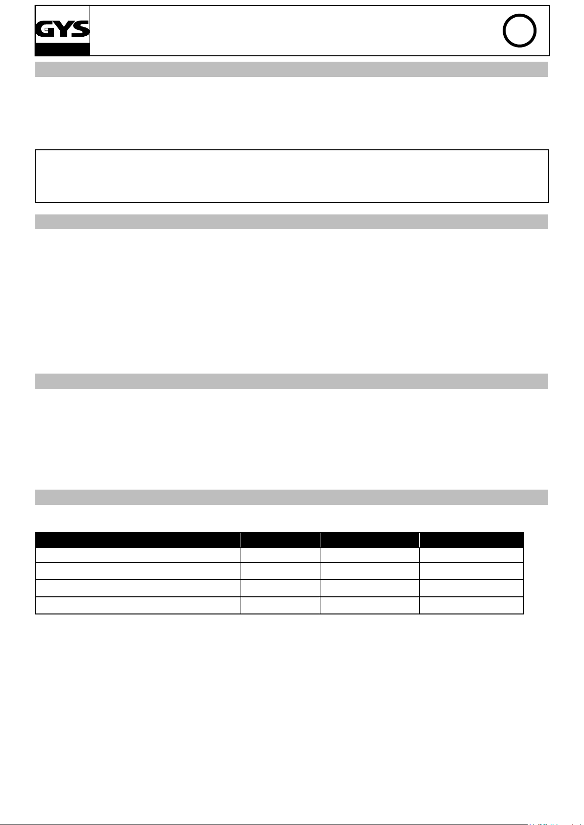
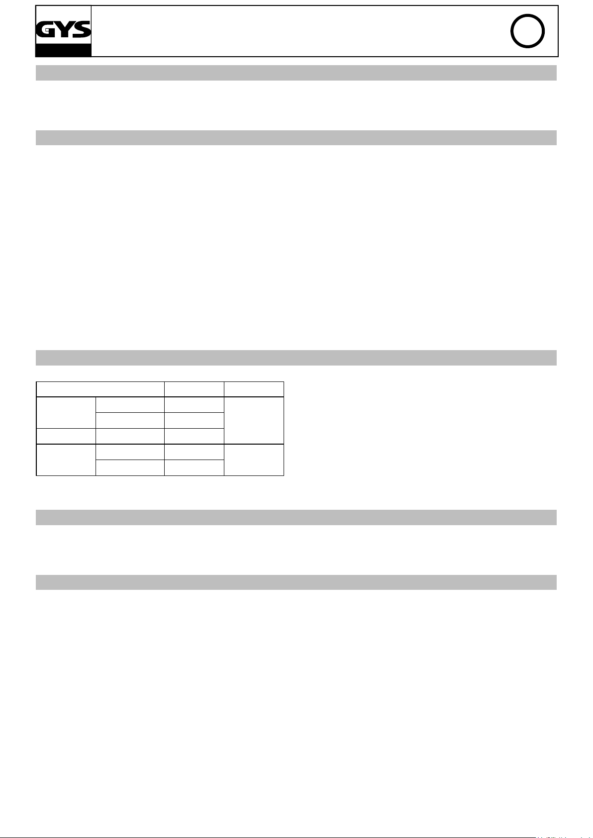
FACTEURS DE MARCHE ET ENVIRONNEMENT D'UTILISATION
• Le poste décrit a une caractéristique de sortie de type "tension constante". Son facteur de marche selon la norme
EN60974-1 est indiqué dans le tableau suivant :
x/60974-1 @ 40°C I max 60% 100%
Trimig 200-4S 200A @ 30% 140A 120A
Trimig 250-4S 250A @ 30% 180A 140A
Trimig 300-4S et G
Trimig 350-4S DUO et G DV 350A @ 35% 270A 220A
Note : les essais d’échauffement ont été effectués à température ambiante et le facteur de marche à 40 °C a été
déterminé par simulation.
300A @ 35% 240A 180A
• Ces appareils sont de Classe A. Ils sont conçus pour un emploi dans un environnement industriel ou professionnel.
Dans un environnement différent, il peut être difcile d’assurer la compatibilité électromagnétique, à cause de perturbations conduites aussi bien que rayonnées. Ne pas utiliser dans un environnement comportant des poussières métalliques
conductrices.
• Les Trimig sont conformes à la CEI 61000-3-12, à condition que la puissance de court-circuit Ssc soit supérieure ou
égale à 3,9MVA sauf 200-4S à 2,8MVA au point d’interférence entre l’alimentation de l’utilisateur et le réseau public
de distribution. Il est de la responsabilité de l’installateur ou de l’utilisateur du matériel de s’assurer, si nécessaire en
consultant l’exploitant du réseau de distribution, que le matériel est raccordé uniquement à l’alimentation telle que la
puissance du court-circuit Ssc soit supérieur ou égale 3,9MVA sauf 200-4S à 2,8MVA.
6
TRIMIG
DESCRIPTION
Thank you for choosing this product;
please read this instruction manual carefully before installing and using the product and keep in a safe place for future
reference.
The Trimig are semi-automatic welding units; they are ventilated for semi-automatic welding (MIG or MAG) and are
capable of welding steel, stainless steel and aluminium. Adjustment is quick and easy with their «synergic wire speed»
function. They work on a 400V three-phase power supply, and /or 230V three-phase for the DV models.
ELECTRICITY SUPPLY
The absorbed current (I1eff) is indicated on the device for use at maximum settings. Check that the power supply and
its protection (fuse and/or circuit breaker) are compatible with the current needed during use. The device must be
placed in such way that the power socket is always accessible. Do not use an extension cable which has a wire section
smaller than 4 mm². These products are supplied with a 16A or 32A plug type EEC RS/015. They should be plugged
in to a 400V (3PH) power socket WITH earth and protected by a 16A circuit breaker and 1 differential 30mA. 230V
3-phase power supply, for Trimig 250-4S DV, 350 G DV and 350-4S DUO DV: WARNING: This device is pre-built in 400V
three-phase. If your electrical installation is 230V three-phase, you must modify the connection on the terminal board.
This modication must be undertaken by qualied personnel. In order to do so, please refer to the technical diagram
inside the product. The plug must be protected by a 16A or 25A (for models 350) circuit breaker and 1 differential 30mA.
DEVICE PRESENTATION (FIG II)
EN
1- On / Off switch
2- Power Settings - 2 switches with 7 positions: for adjustment of the welding voltage output. The adjustment
of the output voltage is proportional to the thickness of
the work piece.
3- Control panel – Welding settings (manual or automatic
mode).
4- European standard torch connection.
5- Thermal Protection light: Indicates when a cool-down
period is necessary following intensive use.
6- Torch support.
7- Power Cable (5m).
8- Earth cable connector
SEMI-AUTOMATIC WELDING FOR STEEL / STAINLESS STEEL (MAG MODE) (FIG III)
The Trimig 200-4S can weld 0.6/0.8/1mm steel and stainless steel wires (g. III-A). The device is capable of working
with Ø 1.0 mm steel wire (roller Ø 0.8/1.0, contact tip of 01.0). If using lower diameter wire, you should use change the
contact tip, and ensure that the reversible rollers in the wire feeder are positioned correctly (so that required diameter
is visible when in place). The Trimig 250-4S DV 230-400V can weld 0.8/1/1.2mm steel and stainless steel wires. The
device is capable of working with Ø 1mm steel wire (roller Ø 0.8/1.0, contact tip of 1). The Trimig 300-4S, 300 G, 350-4S
DUO DV and 350 G DV can weld 0.8/1/1.2mm steel and stainless steel wires. The device is capable of working with Ø
1mm steel wire (roller Ø 1.0/1.2, contact tip of 1). For Steel or Stainless Steel, you will need to use specic gas - Argon
+ CO2 (Ar + CO2). The proportion of CO2 will vary depending on usage. The gas ow for steel is between 10 and 20L
/ min depending on the environment and experience of the welder.
9- Gas bottle support (max 1 bottle of 10m3).
10- Fastening chain for bottles. Warning: fasten the
chain securely (see IV-1)
11- Reel support Ø 200 mm/ 300mm.
12- Gas connector (350-4S DUO DV)
13- Torch Cable support
14- Wire feeder solenoid valve 2
15- Wire feeder gas connection for torch 2
16- Wire feeder control cable connector
17- Wire feeder power cable connector
18- Selection switch potentiometer (only on 300G and
350 G DV)
SEMI-AUTOMATIC WELDING FOR ALUMINIUM (MIG MODE) (FIG III)
The Trimig 200-4S can weld 0.8mm and 1mm aluminium wires. (g. III-B). The Trimig 250, 300 and 350 can weld 1mm
and 1.2mm aluminium wires. (g. III-B). To weld aluminium, neutral gas “pure Argon” (AR) is required. For specic gas
requirements seek advice from your gas distributor. The gas ow in aluminium should be between 15 and 25 L / min
depending on the environment and experience of the welder. Things to note when welding with Aluminium
• Set the pressure of the rollers to a minimum so as not to crush the wire
• Remove the capillary tube before connecting the aluminium torch
• When welding aluminium use a special aluminium torch with Teon sheath to reduce friction. Do not cut the sheath
near the connector! It is used to guide the wire from the rollers (g III-B).
• Contact Tip: Use the specic Aluminium contact tip corresponding to the diameter of the wire.
7
TRIMIG
SEMI-AUTOMATIC BRAZING FOR HIGH-TENSILE STRENGTH STEELS
The Trimig 200-4S can braze-weld high-tensile strength plates with Cuprosilicium CusI3 wire or Cuproaluminium CuAl8
wire (Ø 0.8 mm and Ø 1 mm). The welder must use a neutral gas: pure argon (Ar). For specic gas requirements seek
advice from your gas distributor. The required gas ow is between 15 and 25L / min.
REEL AND TORCH ASSEMBLY (FIG IV)
Open the door of the machine.
• Position the reel on to the support (3). To place a 200mm wire reel, rst install the adapter (ref. 042889) on the support.
• Adjust the reel brake (4) to avoid the reel movement tangling the wire when welding stops. Be careful not to tighten
too much! Then tighten the plastic screw (2) rmly.
• The wire feeder uses double groove rollers (8) (Ø 0.8/ Ø 1 or Ø 1/ Ø 1.2). The visible diameter on the roller when
tted is the one currently in use. For Ø 1 mm wire, use the Ø 1 groove.
• For rst use:
- Release the xing screw of the wire guide (5).
- Place the rollers, and tighten the screws (9).
- Place the wire guide (7) as close as possible to the roller but without touching it, then tighten the xing screw.
• To select the adjustment of the drive rollers (6) : loosen the knob fully, Start the motor by pressing the trigger of the
torch, tighten the knob whilst pressing the trigger until the wire starts to move. Bend the wire where it comes out of the
nozzle and hold it in place to stop its progress. The setting is correct when the guide roller slides over the wire, even
when it is blocked at the end of the torch.
• Common adjustment of knob (6): scale 3-4 for steel, and scale 2-3 for aluminium.
EN
CHOICE OF REELS
Possible settings:
Type l Torche Gaz
acier
inox
Alu
AG5
*Consider Teon sheath and special aluminium contact tip
GAS COUPLING
Fit the regulator/owmeter to the gas bottle and then t the gas pipe to the connector. To avoid gas leaks use the collars
provided in the accessories box. Ensure proper maintenance of the gas cylinder in accordance with the attachment of
the chain cf. IV-1. Assurer le bon maintient de la bouteille de gaz en respectant la xation de la chaine cf. IV-1
CONTROL PANEL (FIG V)
Welding mode selection (2)
- 2T: two-stage welding
- 4T: 4-stage welding
- SPOT: Spot welding with adjustable spot diameter
Wire speed selection (4)
Wire speed regulator
The speed varies from 1 to 15 m/minute.
SPOT/DELAY setting potentiometer (5)
Manual Mode (1)
In manual mode, the wire speed is determined by the
Ø 300 x
Ø 200 x
Ø 200 x
Ø 300 x*
Ø 200 x*
argon
+
CO2
Argon pur
user by adjusting the potentiometer (4).
Synergic Mode (3)
Position the potentiometer (4) in the middle of the «
OPTIMAL SYNERGIC » zone In this mode, the device
determines the optimum wire speed according to 3 parameters:
- Voltage
- Wire diameter
- The power mode It is possible to adjust the speed wire
+ / -.
8
TRIMIG
"MANUAL" MODE (FIG V)
To set your device, proceed as follows:
• Choose the welding voltage using the 2 power switches (2 and 7 positions)
Example:
For welding Steel - 1 mm with a Ø 0.8 wire, set the switch to «1»
• Adjust the wire speed with potentiometer (4).
Advice:
The wire speed adjustment is often determined by « the noise »: the arc must be stable and emit low crackling. If
the speed is too low, the arc will not be continuous. If the speed is too high, the arc crackles and the wire will push
back the torch.
"SYNERGIC" MODE (FIG V)
This function automatically controls the wire speed. There is no need to set the wire speed manually.
• Position the wire speed potentiometer (4) in the middle of the « Optimal synergic » zone.
• Select:
- Wire type (3)
- Wire diameter (3)
- Power setting (switch on the front)
To select the right position in accordance with the thickness of the work-piece, please refer to the “synergic mode” table
on the previous page. From the settings chosen, the Trimig determines the optimum wire speed and the device is ready
to weld. It is also possible to adjust the wire speed if necessary by adjusting potentiometer + or – manually (4). The
last welding conguration is saved in the memory automatically (wire diameter, wire type, mode).
EN
ADVICE AND THERMAL PROTECTION
• Trimig should not be lifted by its handles, torch support, or the top of the machine. When lifting the Trimig, ensure the
weight is fully supported at the bottom of the machine. There must be no gas bottle connected during this operation.
• Always respect the basic rules of welding.
• Do not block/cover the ventilation holes of the machine.
• Leave the device plugged in after welding to allow proper cooling down.
• Thermal protection: If the machine becomes too hot, the warning light will illuminate and the machine will stop. Cooling will take a few minutes, the length of time will also depend on the external temperature.
DUTY CYCLE AND WELDING ENVIRONMENT IN USE
• The welding unit describes an output characteristic of "constant current" type. The duty cycles following the standard
EN60974-1 (at 40°C on a 10mn cycle) are indicated in the table below:
x/60974-1 @ 40°C I max 60% 100%
Trimig 200-4S 200A @ 30% 140A 120A
Trimig 250-4S 250A @ 30% 180A 140A
Trimig 300-4S et G
Trimig 350-4S DUO et G DV 350A @ 35% 270A 220A
Note : The machines’ duty cycle has been tested at room temperature (40°C) and has been determined by simulation.
• These are Class-A devices. They are designed to be used in an industrial or professional environment. In a different environment, it can be difcult to ensure electromagnetic compatibility, due to conducted disturbances as well as radiation.
300A @ 35% 240A 180A
• These devices comply with IEC 61000-3-12, provided that the power of the short-circuit Ssc is equal to or greater than
3.9MVA (2.8MVA for the Trimig 200-4S) at the interface between the machine and the mains power network. It is the
responsibility of the installer or user of the equipment to ensure if necessary by consulting the operator of the mains
electricity, that the equipment is only connected to a power supply where the power of short-circuit ssc is equal to or
greater than 3,9MVA (2.8MVA for the Trimig 200-4S).
9

TRIMIG
BESCHREIBUNG
Wir freuen uns, dass Sie sich für ein Markengerät der Firma GYS entschieden haben und danken Ihnen für das entgegengebrachte Vertrauen. Bitte lesen Sie vor dem Erstgebrauch der Anlage sorgfältig diese Betriebsanleitung und machen Sie sie jedem Anwender zugänglich, um eine einwandfreie Inbetriebnahme, Bedienung und Wartung des Gerätes
zu gewährleisten.
Die TRIMIG sind synergisch geregelte, fahrbare Schutzgasschweißgeräte, konzipiert um MIG/MAG Schweißarbeiten an
Stahl-, Edelstahl- und Aluminiumblechen durchzuführen. Aufgrund der Funktion «synergische Drahtvorschubgeschwindigkeit» ist die Handhabung dieser Geräte schnell und einfach. Netzanschluss: 400V dreiphasig oder 230V dreiphasig
(DV Modell).
NETZANSCHLUSS
Für den Einsatz des Gerätes bei Maximaleinstellungen, ist der aufgenommene Strom (I1eff) am Gerät aufgedruckt.
Überprüfen Sie, ob die Stromversorgung und die Schutzeinrichtungen (Sicherungen und/oder Schutzschalter) mit dem
Strom, den Sie beim Schweißen benötigen, übereinstimmen. Achten Sie beim Aufstellen des Gerätes darauf, dass der
Netzstecker immer frei zugänglich ist. Benutzen Sie kein Verlängerungskabel, dessen Querschnitt kleiner als 4mm² ist.
Diese Geräte werden mit einem 16A (TRIMIG 200, 250 und 300) bzw. 32A Netzstecker (TRIMIG 350) - Typ RS-015 CEE
400V- geliefert und müssen an eine dreiphasige 400V Steckdose + Erde (abgesichert durch 16A Kurve D Sicherung
30A Typ mA) angeschlossen werden. Netzanschluss an eine dreiphasige 230V Steckdose + Erde: TRIMIG 250-4S DV,
350 G DV und 350-4S DUO DV. ACHTUNG! Diese Geräte sind für einen dreiphasigen 400V Netzanschluss werkseitig
voreingestellt. Bei Anschluss an ein dreiphasiges 230V Stromnetz müssen die Anschlüsse entsprechend dem im Geräteinneren aufgedruckten 230V Schaltplan geändert werden. Diese Änderungen dürfen ausschließlich von technischem
Fachpersonal durchgeführt werden. Der Netzstecker muss durch einen 16A bzw. 25A (TRIMIG 350) Leistungsschalter
mit 30mA FI abgesichert sein.
DE
BESCHREIBUNG (S. ABB. II)
1- Netzschalter Ein/Aus
2- Feinstufenregler zur Anpassung der Schweißleistung
adäquat zur zu verschweißenden Blechstärke
3- Bedienfeld zur Schweißparametereinstellung (Modus
Manuell oder Synergic)
4- Eurozentralanschluss zum Anschluss der Schweißbrenner
5- Kontrolllampe für Thermoüberwachung: Meldet Überlastung bei Überschreiten der maximalen Einschaltdauer
(Abkühlung des Gerätes von mehreren Minuten notwendig)
6- Vorderer Brennerhalter
7- Netzstromkabel
8- Anschluss Masseklemme
9- Auageplatte für Gasasche (max.1 x 10m³ Gasasche)
SYNERGISCHES STAHL-/ EDELSTAHL- SCHWEISSEN (MAG MODUS) (ABB. III)
Das Trimig 200-4S eignet sich zum Verschweißen von 0,6/0,8/1mm Stahl- und Edelstahldrähten (Abb. III-A). Das
Gerät ist werkseitig für den Betrieb mit Ø1,0mm Stahldraht voreingestellt (Kontaktrohr Ø1,0 - Drahtrolle Ø0,8/1,0). Bei
Gebrauch von Draht mit kleinerem Durchmesser, tauschen Sie entsprechend das Kontaktrohr aus. Die Drahtförderrollen
weisen je zwei verschiedene Drahtaufnahmenuten auf (z.B. Ø 0,6/0,8mm). Die zu wählende Nutenbreite ist seitlich auf
der Rolle gekennzeichnet. Mit dem Trimig 250-4S DV 230-400V lassen sich 0,8/1,0/1,2mm Stahl- und Edelstahldrähte
verschweißen. Das Gerät ist werkseitig für den Betrieb mit Ø1,0mm Stahldraht voreingestellt (Drahtrolle Ø 0,8/1). Die
Trimig 300-4S, 300 G, 350-4S DUO DV und 350 G DV können 0,8/1/1,2mm Stahl- und Edelstahldrähte verschweißen.
Die Geräte sind werkseitig für den Betrieb mit Ø1,0mm Stahldraht voreingestellt (Drahtrolle Ø1,0/1,2). Stahl- und
Edelstahlschweißen erfordern die Verwendung spezischer Mischgase z.B. Argon + CO2 (Ar+CO2). Der Mengenanteil
des CO2 variiert je nach Einsatzzweck. Empfehlung: Fragen Sie den Gasfachhandel nach dem optimalen Gas bei außergewöhnlichen Anwendungen. Die Gasdurchussmenge bei Stahlschweißarbeiten beträgt in der Regel 10 bis 20 L/min,
je nach Umgebungsverhältnissen und individuellen Bedürfnissen des Schweißers.
10- Sicherungskette für Gasaschen Achtung! Gasaschen stets gegen Rutschen und Kippen sichern (Abb.
IV-1)!
11- Aufnahmedorn für Drahtrolle Ø 200mm oder 300mm
12- Schutzgasanschluss 1 (Magnetventil) (350-4S DUO
DV)
13- Hinterer Brennerhalter
14- Schutzgasanschluss 2 (Eingang für separates Drahtvorschubgerät)
15- Schutzgasanschluss 2 (Ausgang für separates Drahtvorschubgerät)
16- Steueranschluss separates Drahtvorschubgerät
17- Leistungsanschluss (Schweißstrom) separates Drahtvorschubgerät
18- Potentiometer Auswahlschalter (nur 300G und 350G
DV)
SYNERGISCHES ALUMINIUM - SCHWEISSEN (ABB. III)
Das Trimig 200-4S kann 0,8mm und 1mm Aluminiumdrähte verschweißen (Abb. III-B). Die Trimig 250, 300 und 350
eignen sich zum Verschweißen von 1mm und 1,2mm Aluminiumdrähten (Abb.III-B). Um Aluminium zu schweißen, ist
10

TRIMIG
die Verwendung des neutralen Gas „Rein-Argon” (Ar) erforderlich. Empfehlung: Fragen Sie den Gasfachhandel nach
dem optimalen Gas für Ihre jeweilige Anwendung. Die Gasdurchussmenge bei Aluminiumschweißarbeiten beträgt in
der Regel 15 bis 25 L/min, je nach Umgebungsverhältnissen und individuellen Bedürfnissen des Schweißers. Wichtige
Hinweise für Aluminiumschweißen:
• Der weiche Aluminiumdraht sollte mit möglichst geringem Anpressdruck zwischen den Drahtförderrollen transportiert
werden, da er andernfalls deformiert und ungleichmäßig gefördert wird.
• Kapillarrohr: Bei dem Einsatz eines speziellen Aluminiumbrenners sollte das im Zentralanschluss steckende Rohr entfernt werden.
• Brenner: Verwenden Sie einen speziellen Brenner für Aluminium. Dieser Brenner verfügt über eine Kunststoffführungsseele, die die Reibung während der Drahtförderung im Schlauchpaket reduziert. Schneiden Sie die Kunststoffseele unter keinen Umständen direkt am Zentralanschluss ab! Die Seele dient dazu den Draht unmittelbar von den Rollen
zu übernehmen (Abb. III-B).
• Kontaktrohr: Benutzen Sie ein Kontaktrohr SPEZIELL für Alu, das dem gewählten Drahtdurchmesser entspricht.
SEMI-AUTOMATISCHES LÖTEN VON HOCHFESTEM STAHL
Das Trimig 200-4S wird von Automobilherstellern für Lötarbeiten von hochfesten Stahlblechen mit einem Kupfer-Silizium- (CuSI3) oder Kupfer-Aluminium (CuAl8) -Draht (Ø 0.8 mm und Ø 1 mm) empfohlen. Als Schutzgas wird „ReinArgon“ (Ar) benötigt. Empfehlung: Fragen Sie den Gasfachhandel nach dem optimalen Gas bei außergewöhnlichen
Anwendungen. Die Gasdurchussmenge beträgt in der Regel 15 bis 25L/min, je nach Umgebungsverhältnissen und
individuellen Bedürfnissen des Schweißers.
DE
MONTAGE VON DRAHTFÜHRUNG UND BRENNER (ABB. IV)
Öffnen Sie die seitliche Geräteverkleidung.
• Positionieren Sie die Drahtrolle auf dem Aufnahmedorn (3) des Haspelträgers. Um eine 200mm Drahtrolle zu verwenden, müssen Sie zuerst einen Adapter (Art.-Nr. 042889) am Haspelträger anbringen.
• Justieren Sie die Drahtrollenbremse (4), um die Drahtrolle bei Schweißstopp gegen Nachdrehen zu sichern. Ziehen Sie
die Drahtrollenbremse generell nicht zu fest! Ziehen Sie die Halterungsschraube (2) fest.
• Die Antriebsrollen (8) sind mit 2 Führungsnuten versehen (Ø 0,8/ Ø 1 bzw. Ø 1/ Ø 1,2). Der seitlich sichtbare Wert
entspricht der aktuellen Nutbreite. Verwenden Sie für den jeweiligen Drahtdurchmesser ausschließlich die passende Nut.
• Drahttransport-Montage:
- Lockern Sie die Fixierungsschrauben (5) der Drahtführung.
- Legen Sie die Drahttransportrollen mit der passenden Nut ein und ziehen Sie die Halterungsschraube (9) fest.
- Positionieren Sie die Drahtführung (7) so nah wie möglich an der Transportrolle. Die Drahtführung darf keinen Kontakt
mit der Transportrolle haben. Ziehen Sie nun die Fixierungsschrauben wieder an.
• Um den Transportdruck (6) korrekt einzustellen, betätigen Sie bei eingelegtem Draht den Brennertaster und justieren
die Andruckmutter so, dass der Draht konstant transportiert wird. Zu starker Andruck wirkt sich negativ aus. Legen
Sie zur Kontrolle den aus dem Kontaktrohr austretenden Draht zwischen Daumen und Zeigenger und lösen Sie den
Brennertaster aus. Wird der Draht bei leichtem Fingerdruck noch konstant gefördert, ist der Antrieb korrekt eingestellt.
• Übliche Andruckeinstellung des Drahttransportes (6): 3-4 für Stahl und 2-3 für Aluminium.
DRAHTROLLENAUSWAHL
Mögliche Kongurationen:
Type l Torche Gaz
acier
inox
Alu
AG5
Ø 300 x
Ø 200 x
Ø 200 x
Ø 300 x*
Ø 200 x*
argon
+
CO2
Argon pur
*zusätzlich empfohlen: Teonseele und Kontaktrohre speziell für Alu. Entfernen Sie das Kapillarrohr.
GAS-ANSCHLUSS
Montieren Sie zuerst den Druckminderer an der Gasasche und schließen Sie danach den Gasschlauch (1) an. Um Gasverlust zu vermeiden, verwenden Sie die in der Zubehörbox enthaltenen Schlauchklemmen. Achten Sie stets darauf,
dass sich die Gasasche in einem senkrecht stehenden und –mit Hilfe der Sicherungskette (Abb.IV-1)- ausreichend
gesichertem Zustand bendet.
11

BEDIENEINHEIT (ABB. V)
TRIMIG
DE
Auswahl Brennertastermodus (2)
- NORMAL (2T): Standard 2
-Takt Schweißen - NORMAL (4T): Standard 4
-Takt Schweißen - DELAY: Funktion «Schweißpause»
- SPOT: Funktion «Heftschweißen» (Intervallschaltung
zum Heften), Einstellung des Schweißpunktdurchmessers.
Einstellung der Drahtvorschubgeschwindigkeit mittels
Potentiometer (4) von 1 bis 15m/min.
SPOT/DELAY Einstellungspotentiometer (5)
Manuell Modus (1)
Im Manuell Modus wird die Drahtvorschubgeschwindig-
«MANUELL» MODUS (ABB. V)
Gehen Sie wie folgt vor, um Ihr Gerät adäquat einzustellen:
• Stellen Sie die Schweißspannung je nach Gerät mittels Schalter 7-10-12 bzw. 2 Stufenschalter (2/7 Stufen) entsprechend
der Blechdicke ein.
- Beispiel:
Um 1mm Stahlbleche mit Ø 0,8mm Draht zu verschweißen, Schweißspannungsregler auf 1 stellen.
• Drahtvorschubgeschwindigkeit mittels Potentiometer (4) anpassen.
Tipp:
Die korrekte Drahtvorschubgeschwindigkeit ist am Abbrandgeräusch zu erkennen: Der Lichtbogen sollte stabil und
ohne große Spritzerbildung brennen. Wenn die Geschwindigkeit zu gering ist, brennt der Lichtbogen nicht kontinuierlich. Wenn die Geschwindigkeit zu hoch ist, erzeugt der Lichtbogen Spritzer und drückt den Brenner weg.
keit mittels Potentiometer vom Anwender eingestellt (4).
Synergic Modus (3)
Im Synergic Modus muss die Drahtvorschubgeschwindigkeit nicht manuell eingestellt werden: Stellen Sie das
Potentiometer (4) in der Mitte der «OPTIMAL SYNERGIC»
Zone ein und wählen Sie aus:
- Drahttyp
- Drahtdurchmesser
- Schweißleistung Das Gerät stellt anhand dieser Angaben
automatisch die optimale, werkseitig voreingestellte Drahtvorschubgeschwindigkeit ein. Diese kann mittels Drahtvorschubpotentiometer manuell feinreguliert werden.
«SYNERGIC» MODUS (ABB. V)
Im Synergic Modus muss die Drahtvorschubgeschwindigkeit nicht manuell eingestellt werden:
• Stellen Sie das Potentiometer (4) in der Mitte der «OPTIMAL SYNERGIC» Zone ein
• Wählen Sie aus:
- Drahttyp (3)
- Drahtdurchmesser (3)
- Schweißleistung (Stufenschalter auf der Frontseite).
Wählen Sie die richtige Position je nach Blechstärke. Orientieren Sie sich an der Referenztabelle «Synergic Modus»
auf voriger Seite. Anhand dieser Parameter stellt das Gerät automatisch die optimale Drahtvorschubgeschwindigkeit
schweißbereit ein. Eine Feinregulierung erfolgt hier im «Optimal Synergic»- Bereich des Drahtvorschubpotentiometers
(4). Für die jeweiligen Brenner wird die letzte Einstellung für Drahtdurchmesser, Drahttyp und Modus gespeichert.
HINWEISE
• Das Gerät darf nicht an den Handgriffen, den Brennerhaltern oder dem oberen Teil des Gerätes, sondern nur von
unten angehoben werden. Die Gasasche darf nicht erst während des Schweißvorgangs aufgestellt werden.
• Beachten Sie bitte die Grundregeln des Schweißens.
• Verschließen Sie nicht die Lüftungsöffnungen des Gerätes, um eine Luftzirkulation zu ermöglichen.
• Lassen Sie das Gerät nach Beendigung der Arbeit noch eine Zeit eingeschaltet, um die Abkühlung zu ermöglichen.
• Thermoschutz: Nach Aueuchten der Kontrollampe benötigt das Gerät je nach Umgebungstemparatur einige Minuten
zur Abkühlung.
12

TRIMIG
EINSCHALTDAUER – UMGEBUNGSBEDINGUNGEN
Das Gerät arbeitet mit einer „Konstantstrom-Kennlinie“. Die Angaben für die Einschaltdauer folgen der Norm EN60974-1
und werden in nachfolgender Tabelle angezeigt:
x/60974-1 @ 40°C I max 60% 100%
Trimig 200-4S 200A @ 30% 140A 120A
Trimig 250-4S 250A @ 30% 180A 140A
DE
Trimig 300-4S et G
Trimig 350-4S DUO et G DV 350A @ 35% 270A 220A
Hinweis : Der Überhitzungstest wurde bei Raumtemperatur durchgeführt und die Einschaltdauer bei 40°C durch
Simulation ermittelt.
• Das Gerät ist für den industriellen und/ oder professionellen Gebrauch geeignet und entspricht der Norm CISPR 11.
In einem anderen Umfeld ist die elektromagnetische Verträglichkeit schwieriger zu gewährleisten. Verwenden Sie das
Gerät nicht in Räumen, in denen sich in der Luft metallische Staubpartikel benden, die Elektrizität leiten können.
• Vorausgesetzt, dass die Kurzschlussleistung Ssc an der Schnittstelle zwischen privatem Nutzer und öffentlichem Versorgungsnetz größer oder gleich 3,9MVA (2.8MVA für das Trimig 200-4S) ist, stimmen diese Geräte mit der Norm EN
61000-3-12 überein. Es liegt in der Verantwortung des Elektroinstallateurs bzw. des Geräteanwenders dafür Sorge zu
tragen, dass das Gerät ausschließlich an eine Stromversorgung mit einer Kurzschlussleistung Ssc größer oder gleich
3.9MVA (2.8MVA für das Trimig 200-4S) angeschlossen wird. Wenden Sie sich bei eventuellen Fragen bitte an den lokalen Stromnetzbetreiber.
300A @ 35% 240A 180A
13

TRIMIG
DESCRIPCION
Gracias por elegir uno de nuestros equipos. Para obtener el rendimiento máximo, lea con atención el siguiente documento:
Los Trimig son equipos de soldadura semiautomáticos, « sinérgicos » y sobre ruedas, ventilados para la soldadura MIG
o MAG. Son recomendados para soldar aceros, inox y aluminio. Sus reglajes son sencillos y rápidos gracias a la función
« velocidad de hilo sinérgica ». Funcionan con una alimentación 400V trifásica o 230V trifásica para los modelos DV.
ALIMENTACION ELECTRICA
La corriente efectiva absorbida (I1eff) está indicada sobre el equipo para condiciones de uso máximas. Comprobar que
la alimentación y sus protecciones (fusible y/o disyuntor) sean compatibles con la corriente necesaria en utilización. El
equipo debe ser colocado de tal manera que la toma de tierra sea accesible. No utilizar alargador con una sección inferior a 4 mm². Los Trimig están entregados con una toma de 16A tipo EEC RS/015. Tienen que conectarse a una toma
de 400 V-3 fases CON tierra protegida por un disyuntor de 16A y un diferencial de 30mA. Alimentación 230V trifásica de
los Trimig 250-4S DV, 350: G DV y 350-4S DUO DV: CUIDADO: este aparato está montado de fábrica en 400V trifásica.
Si su instalación eléctrica es a 230V trifásica, sírvase modicar la conexión de la placa de bornes al interior del aparato.
Esta manipulación tiene que realizarse por una persona cualicada. Referirse al esquema al interior del aparato. La toma
tiene que ser protegida por un disyuntor de 16A o 25A (para modelos 350) y un diferencial de 30mA.
DESCRIPCION DEL EQUIPO (IL. II)
ES
1- Interruptor 0-I de arranque- paro
2- Reglaje de potencia por un conmutador: permite
ajustar la tensión de salida del generador. El ajuste de la
tensión de salida es proporcional al espesor del material
que va a soldar.
3- Teclado de reglajes de los parámetros de soldadura.
(Modo manual o automático).
4- Racores de la antorcha al estándar europeo.
5- Piloto de protección térmica sobre el teclado de
mando: Advierte que el equipo se desconectará al usarse
de manera intensiva (el paro durará unos diez minutos).
6- Soporte delantero de antorchas
7- Cable de alimentación (5m)
8- Salida pinza de masa.
SOLDADURA SEMI-AUTOMATICA ACERO / INOX (MODO MAG) (IL. III)
El Trimig 200-4S puede soldar hilo de acero e inox de 0.6/0.8 y 1mm (Ilustración III-A). El equipo está entregado de
origen para funcionar con hilo de Ø 1.0 mm para acero (tubo de contacto de 1.0, rodillos Ø 0.8/1.0). Al utilizar un hilo de
diámetro inferior; conviene cambiar de tubo de contacto. El rodillo de la devanadera es un rodillo reversible. Colocarlo de
tal manera que se pueda leer el diámetro deseado al lado visible del rodillo. El Trimig 250-4S DV 230-400V puede soldar hilo de acero e inox de 0.8/1 y 1.2mm. El equipo está entregado de origen para funcionar con hilo de Ø 1 mm para
acero (rodillos Ø 0.8/1 acero/inox). Los Trimig 300-4S, 300 G, 350-4S DUO DV y 350G DV pueden soldar hilo de acero
e inox de 0.8/1 y 1.2mm. El equipo está entregado de origen para funcionar con hilo de Ø 1mm para acero (rodillos Ø
1/1.2 acero/inox). La utilización en acero o inox necesita un gas especíco a la soldadura argón + CO2 (Ar + CO2). La
relación de CO2 varía según la utilización. Para elegir el gas, pedir consejos a un distribuidor de gas. El caudal de gas
para soldar el acero se sitúa entre 10 y 20 L/mn según el ambiente y la experiencia del soldador.
9- Soporte de botellas (1 botella de 10m3 como máximo).
10- Cadena de jación de botellas. Atención: bien jar las
botellas (Il. IV-1).
11- Soporte bobina Ø 200 o 300 mm.
12- Entrada de gas (350-4S DUO DV)
13- Soporte de cables de antorchas
14- Entrada gas 2 de la devanadera
15- Salida gas 2 de la devanadera
16- Conector de mando de la devanadera
17- Conector de potencia de la devanadera
18- Interruptor de selecciόn del potenciómetro (solo para
los 300G y 350 G DV)
SOLDADURA SEMI-AUTOMATICA ALUMINIO (MODO MIG) (IL. III)
El Trimig 200-4S puede soldar hilo de aluminio de 0.8 y 1mm. (Ilustración III-B). El Trimig 250-4S DV 230-400V puede
soldar hilo de aluminio de 1 y 1.2mm. (Ilustración III-B). Para soldar aluminio, es necesario utilizar un gas neutro: argón
puro (Ar). Para elegir el gas, pedir consejos a un distribuidor de gas. El caudal de gas se sitúa entre 15 y 25 L/mn según
el ambiente y la experiencia del soldador. Abajo las diferencias entre la utilización en soldadura de acero y soldadura
de aluminio:
• La presión de los rodillos prensadores de la devanadera en el hilo: utilizar un mínimo de presión para no aplastar el
hilo.
• Tubo capilar: quitar el tubo capilar antes de conectar la antorcha aluminio con una funda de teón.
• Antorcha: utilizar una antorcha especial aluminio. Esta antorcha está dotada de una funda teón para reducir las
fricciones.
• NO CORTAR la funda al borde del empalme!! Esta funda sirve para guiar el hilo a partir de los rodillos. (Ilustración
III-B)
• Tubo de contacto: utilizar un tubo de contacto ESPECIAL aluminio que corresponda al diámetro del hilo.
14

TRIMIG
SOLDADURA BRAZING SEMI AUTOMATICA DE LOS ACEROS DE ALTO LIMITE ELASTICO
El Trimig 200-4S puede soldar chapas de alto límite elástico con un hilo de cuprosilicio CusI3 o cuproaluminio CuAl8
(Ø 0,8mm y Ø 1mm). El soldador debe utilizar un gas neutro: argón puro (Ar). Para elegir el gas, pedir consejos a un
distribuidor de gas. El caudal de gas se sitúa entre 15 y 25 L/mn.
PROCEDIMIENTO DE MONTAJE DE LOS RODILLOS Y ANTORCHAS (IL. IV)
• Abrir el capo del aparato
• Colocar el rollo teniendo en cuenta el espolón de entrada (3) del soporte. Para colocar un rollo de 200mm, es necesario
instalar un adaptador en el soporte (ref. 042889).
• Arreglar el freno (4) del rollo para evitar que, al parar la soldadura, el hilo se enrede por causa de inercia del rollo. De
forma general, no apretar demasiado. Luego, apretar rmemente el tornillo de sostenimiento (2).
• los rodillos motor (8) son rodillos con doble guía (Ø 0,8/ Ø 1 o Ø 1/ Ø 1,2). La indicación que se puede leer en el rodillo
es la que se utiliza. Para un hilo de Ø 1 mm, utilizar la guía de Ø 1.
• Para una primera puesta en marcha:
- Aojar el tornillo de jación de la guía de hilo (5)
- Colocar los rodillos, luego bien apretar el tornillo de jación (9).
- Luego colocar la guía de hilo (7) lo más cerca posible del rodillo pero sin contacto con éste último, luego apretar el
tornillo de jación.
• Para ajustar la moleta de los rodillos prensadores (6), proceder así: aojar como máximo, accionar el motor apretando
el gatillo de la antorcha, cerrar la moleta al mismo tiempo que se aprieta el gatillo. Plegar el hilo al salir de la boquilla.
Colocar un dedo sobre el hilo plegado para impedirlo de avanzar. El ajuste del apriete es bueno cuando los rodillos resbalan en el hilo, aunque el hilo quede bloqueado al cabo de la antorcha.
• Ajuste usual de la moleta de rodillos (6): graduación a 3-4 para acero y graduación a 2-3 para aluminio.
ES
ELECCION DE BOBINAS
posibilidades:
Type l Torche Gaz
acier
inox
Alu
AG5
* Prever una funda de teón y un tubo de contacto especial alu
CONEXION GAS
Apretar el manómetro sobre la botella de gas, luego el tubo de gas al conector. Para evitar las huidas de gas, utilizar las
abrazaderas de la caja de accesorios. Comprobar el buen mantenimiento de la botella de gas según las instrucciones
de jación de la cadena (Il. IV-1). Assurer le bon maintient de la bouteille de gaz en respectant la xation de la chaine
cf. IV-1
TECLADO DE MANDO (IL. V)
Selección del modo soldadura (2)
- 2T: soldadura estándar 2 tiempos
- 4T: soldadura estándar 4 tiempos
- DELAY: función « punto de cadeneta », soldadura discontinua con ajuste de la intermitencia del punto.
- SPOT: función « taponado », soldadura discontinua con
ajuste del diámetro del punto. Ajuste de la velocidad del
hilo (4)
Potenciómetro de ajuste de la velocidad del hilo.
La velocidad varía de 1 a 15 m/minuto.
Potenciómetro de ajuste SPOT/DELAY (5)
Ø 300 x
Ø 200 x
Ø 200 x
Ø 300 x*
Ø 200 x*
argon
+
CO2
Argon pur
Modo Manual (1)
En modo manual, la velocidad del hilo se determina por
el soldador, al ajustar el potenciómetro (4).
Modo Sinérgico (3)
Colocar el potenciómetro (4) a mitad de la zona « OPTIMAL SYNERGIC » En este modo, el equipo determina la
velocidad de hilo óptima a partir de 3 parámetros:
- Tensión
- Diámetro del hilo
- Naturaleza del hilo Es posible ajustar la velocidad del
hilo + / -.
15

TRIMIG
MODO «MANUAL » (IL. V)
Para ajustar su equipo, proceder como sigue:
• Elegir la tensión de soldadura gracias al conmutador 7 posiciones.
- ejemplo:
Para soldar acero de 1 mm con un hilo de 0.8mm de diámetro, colocar el conmutador en posición 1
• Apuntar la velocidad de hilo gracias al potenciómetro (4).
Consejos:
El ajuste de la velocidad de hilo se hace a menudo por el «ruido»: el arco debe ser estable y no crepitar demasiado.
Si la velocidad es demasiado débil, el arco no es continuo. Si la velocidad es demasiado rápida, el arco crepita y el
hilo rechaza la antorcha.
MODO « SYNERGIC » (IL. V)
Gracias a esta función, ya no es necesario ajustar la velocidad del hilo.
• Colocar el potenciómetro (4) de la velocidad de hilo a mitad de la zona « Optimal synergic »
• Seleccionar:
- La naturaleza del hilo (3)
- El diámetro del hilo (3)
- La potencia (conmutador en la cara delantera).
Para elegir la posición adecuada según el espesor que soldar, referirse a la tabla « modo sinérgico » de la página enfrente. A partir de esta combinación de parámetros, este equipo determina la velocidad de hilo óptima y el aparato está
listo para soldar. Luego, es posible ajustar la velocidad del hilo, si es necesario, en + o en – gracias al potenciómetro
(4). Una memorización de las últimas conguraciones de soldadura está efectuada y reactivada después de encender el
aparato otra vez. (Diámetro de hilo, tipo de hilo, modo).
ES
CONSEJOS Y PROTECCION TERMICA
• Esos aparatos no deben ser levantados por sus asas, soportes antorchas o por la bandeja superior sino por la parte
inferior del equipo.
• Respetar las normas clásicas de soldadura.
• Dejar las aletas del aparato libres para la toma y salida del aire.
• Dejar el equipo conectado para permitir el enfriamiento.
• Protección térmica: el piloto luminoso se enciende y el enfriamiento dura algunos minutos.
FACTORES DE MARCHA Y ENTORNO DE UTILIZACION
• El aparato tiene una característica de salida de tipo “tensión constante”. Su factor de marcha según la norma EN609741 está indicado en la siguiente matriz:
x/60974-1 @ 40°C I max 60% 100%
Trimig 200-4S 200A @ 30% 140A 120A
Trimig 250-4S 250A @ 30% 180A 140A
Trimig 300-4S et G
Trimig 350-4S DUO et G DV 350A @ 35% 270A 220A
Nota: los ensayos de calentamiento han sido efectuados con una temperatura ambiente y el factor de marcha a 40ºC
ha sido determinado por simulación.
• Estos aparatos son de Clase A. Son concebidos para un uso en un ambiente industrial o profesional. En un entorno
distinto, puede ser difícil asegurar la compatibilidad electromagnética, a causa de perturbaciones conducidas tan bien
como radiadas. No utilizar en un entorno con polvos metálicos conductores.
300A @ 35% 240A 180A
• Este equipo es conforme a la norma CEI 61000-3-12, bajo condición que la potencia de cortocircuito Ssc sea superior
o igual a 3,9MVA (2.8MVA para el Trimig 200-4S) al punto de interfaz entre la alimentación del usuario y la red publica
de distribución. Es de la responsabilidad del instalador del equipo de asegurarse, si necesario consultando al organismo
responsable de la red de distribución, que el equipo esté conectado únicamente con una alimentación cuya potencia de
cortocircuito Ssc sea superior o igual a 3,9MVA (2.8MVA para el Trimig 200-4S).
16

TRIMIG
ОПИСАНИЕ
Благодарим за Ваш выбор ! Чтобы извлечь максимум пользы от использования аппарата, внимательно прочтите
нижеследующее :
Аппараты Trimig полуавтоматические «синергетические» сварочные аппараты на колесиках, с вентилятором
для сварки (MIG или MAG). Они рекомендуются для сварки стали, нержавейки, алюминия. Быстрая и простая
настройка благодаря функции «синергетическая скорость подачи». Аппараты питаются от трехфазной сети 400В
или 230В для версии «DV».
ЭЛЕКТРИЧЕСКОЕ ПИТАНИЕ
Поглощенный эффективный ток (I1eff) для максимальных условий использования указан на аппарате. Проверьте,
что питание и защиты (плавкий предохранитель и/или предохранитель) соответствуют необходимому для
работы току. Аппарат должен быть помещен таким образом, чтобы штепсельная вилка была доступна. Не
используйте удлинителя сечением меньше, чем 4 мм². Эти аппараты поставляются с вилкой 16A или 32A типа
CEE RS/015. Их нужно подключить к трехфазной розетке 400В С ЗАЗЕМЛЕНИЕМ , защищенной предохранителем
16A и дифференциалом 30мA. ТРЕХФАЗНОЕ ПИТАНИЕ 230В ДЛЯ Trimig 250-4S DV, 350 G DV и 350-4S DUO DV :
ВНИМАНИЕ : Изначально этот аппарат смонтирован на для трехфазного питания на 400В. Если у вас трехфазная
электропроводка на 230В, необходимо изменить подключение платы с клеммами внутри аппарата. Эта операция
должна быть сделана компетентным специалистом. Для этого воспользуйтесь схемой подключения на 230В,
расположенной внутри аппарата. Электрическое питание должно быть защищено 16-Aмперным (25 для 350-4S
DUO DV и 350 G DV) предохранителем и дифференциалом 30мA.
RU
ОПИСАНИЕ АППАРАТА (РИС. II)
1- Выключатель вкл – выкл
2- Регулировка одном переключателем (7-ми
позиционными) позволяет настроить сварочное
напряжение на выходе источника. Регулировка
выходного напряжения пропорциональна толщине
свариваемого материала.
3- Клавишная панель регулировки сварочных
параметров (ручной или автоматический режим).
4- Разъем для горелки европейского стандарта.
5- Индикатор термозащиты на клавишной панеле
управления: предупреждает об отключении
вследствие перегрева, когда аппарат используется
слишком интенсивно (отключение на несколько
минут).
6- Подставка для горелки на передней панеле
7- Шнур питания (5м)
ПОЛУАВТОМАТИЧЕСКАЯ СВАРКА СТАЛИ / НЕРЖАВЕЙКИ (РЕЖИМ MAG) (РИС. III)
Trimig 200-4S может варить проволоку из стали и нержавейки диам. 0,6/0,8 и 1 мм (рис. III-A). Он поставляется
оснащенным для работы со стальной проволокой Ø 1,0мм (ролики Ø 0,8/1 сталь/нержавейка, контактная трубка
Ø 1.0). При работе с проволокой меньшего диаметра следует заменить контактную трубку. Ролик подающего
механизма является двусторонним роликом. В этом случае нужно установить его так, чтобы читалась надпись
выбранного диаметра на видимой стороне ролика. Trimig 250-4S DV может варить проволоку из стали и
нержавейки диам. 0,8/1 и 1,2 мм. Он поставляется оснащенным для работы со стальной проволокой Ø 1мм
(ролики Ø 0,8/1 сталь/нержавейка, контактная трубка Ø 1). Trimig 300-4S, 300 G, 350-4S DUO DV и 350 G DV
могут варить проволоку из стали и нержавейки диам. 0,8/1 и 1,2 мм. Они поставляются оснащеннымы для
работы со стальной проволокой Ø 1мм (ролики Ø 1/1,2 сталь/нержавейка, контактная трубка Ø 1). Сварка стали
или нержавейки требует использования специфической газовой смеси аргон + CO2 (Ar + CO2). Пропорция CO2
колеблется в зависимости от использования. Для выбора газа спросите совета у вашего поставщика газа. Расход
газа при сварке стали между 10 и 20 л/мин в зависимости от окружающей среды и опыта сварщика.
8- Выход для зажима массы.
9- Подставка для баллона (баллон максимум 10 м3).
10- Цепь для крепления баллона. Внимание : хорошо
закрепите баллон ((рис. IV-1)
11- Держатель бобины Ø 200/300 мм.
12- Вход газа (350-4S DUO DV)
13- Держатель для кабелей на задней панеле.
14- Вход газа №2 отдельного подающего устройства
15- Выход газа №2 отдельного подающего устройства
16- Коннектор управления отдельного подающего
устройства
17- Коннектор мощности отдельного подающего
устройства
18- Переключатель выбора на потенциометре (только
для 300G и 350 G DV)
ПОЛУАВТОМАТИЧЕСКАЯ СВАРКА АЛЮМИНИЯ (РИС. III)
Trimig 200-4S может варить алюминиевую проволоку 0,8 мм и 1 мм (рис. III-B). Trimig 250, 300 и 350 могут варить
алюминиевую проволоку 1 мм и 1,2 мм (рис. III-B). Для сварки алюминия нужен нейтральный газ: чистый аргон
(Ar). Для выбора газа спросите совета у вашего поставщика газа. Расход газа при сварке между 15 и 25 л/мин в
зависимости от окружающей среды и опыта сварщика. Ниже указаны различия использования для сварки стали
и алюминия:
17

TRIMIG
• Давление прижимных роликов подающего механизма на проволоку: отрегулируйте минимальное давление,
чтобы не раздавить проволоку.
• Капиллярная трубка: снимите капиллярную трубку перед подключением горелки для алюминия с тефлоновым
шлангом.
• Горелка: используйте специальную горелку для алюминия. Эта горелка имеет тефлоновый шланг, который
уменьшает трение. НЕ ОТРЕЗАТЬ шланг по краю стыка ! этот шланг нужен для направления проволоки от
роликов (рис. III-B).
• Контактная трубка : используйте СПЕЦИАЛЬНУЮ контактную трубку для алюминия, соответствующую диаметру
проволоки.
ПОЛУАВТОМАТИЧЕСКАЯ СВАРКА-ПАЙКА ВЫСОКОПРОЧНЫХ СПЛАВОВ
Trimig 200-4S может варить высокопрочные сплавы проволокой CusI3 или CuAl8 (Ø 0,8мм и 1мм). Сварщик
должен использовать нейтральный газ: чистый аргон (Ar). Для выбора газа спросите совета специалиста по
продаже газа. Расход газа приблизительно между 15 и 25 Л/мин.
ПРОЦЕДУРА МОНТАЖА БОБИН И ГОРЕЛОК (РИС. IV)
• Откройте люк аппарата.
• Позиционируйте бобину, учитывая ведущий палец (3) держателя бобины. Для установки бобины 200 мм
установите сначала на держатель переходник (арт. 042889).
• Отрегулируйте тормоз бобины (4), чтобы при остановке сварки бобина по инерции не запутала проволоку. Не
зажимайте слишком сильно ! Затем крепко затяните придерживающий винт (2).
• Движущие ролики (8) с двойным желобом (Ø 0,8/ Ø 1 или Ø 1/ Ø 1,2). Используемый диаметр должен читаться
на ролике. Для проволоки Ø 1 мм используйте желоб Ø 1.
• Первый запуск в работу :
- отвинтите крепежный винт нитевода (5)
- установите ролики, хорошо затените придерживающий винт (9).
- затем позиционируйте нитевод (7) как можно ближе к ролику, но чтобы они не контактировали друг с другом,
затем затяните крепежный винт.
• Чтобы отрегулировать колесико нажимных роликов (6), действуйте следующим образом : максимально
разожмите, приведите в движение мотор нажатием на кнопку горелки, закрутите колесико, продолжая
нажимать на кнопку горелки. Загните проволоку на выходе из сопла. Прижмите проволоку пальцем, чтобы она
не выдвигалась дальше. Сжатие правильно отрегулировано, когда ролики прокручиваются по проволоке, даже
если проволока заблокирована на выходе горелки.
• Регулировка тока колесика роликов (6): шкала 3-4 для стали и шкала 2-3 для алюминия.
RU
ВЫБОР БОБИН
Возможные конфигурации:
Type l Torche Gaz
acier
inox
Alu
AG5
* Вам потребуется тефлоновый шланг и специальная контактная трубка для алюминия. Снимите капиллярную
трубку. Убедитесь в хорошей поддержке газового баллона принимая во внимание закрепление цепи (рис. IV-1).
ПОДСОЕДИНЕНИЕ ГАЗА
Привинтите редуктор к газовому баллону, затем подсоедините шланг (в комплекте) к разъему газа. Во избежание
утечки газа воспользуйтесь стяжными хомутиками (в коробке с аксессуарами). Assurer le bon maintient de la bouteille de gaz en respectant la xation de la chaine cf. IV-1
Ø 300 x
Ø 200 x
Ø 200 x
Ø 300 x*
Ø 200 x*
argon
+
CO2
Argon pur
18

КЛАВИШНОЕ УПРАВЛЕНИЕ (РИС. V)
TRIMIG
RU
Выбор режима сварки (2)
- 2T : 2-тактная сварка
- 4T : 4-тактная сварка
- DELAY : функция «цепного шва», прих-ватка с
регулированием прерывистости точек
- SPOT : функция «заваривания», прихватка с
регулируемым диам.
Точки Регулировка скорости подачи (4)
Потенциометр точной настройки скорости подачи.
Скорость колеблется от 1 до 15 м/мин.
Потенциометр настройки SPOT/DELAY (5)
РЕЖИМ «MANUAL» (РИС. V)
Для настройки аппарата действуйте следующим образом :
• Выберите сварочное напряжение с помощью переключателя 7 позиций.
- например :
Для сварки 1 мм стали, поставьте переключатель на 1 и настройте скорость подачи с помощью потенциометра
(4).
Советы
Настройка скорости подачи делается, как правило, « на слух » : дуга должна быть стабильной и слабо
потрескивать. При слабой скорости подачи дуга прерывается. При высокой скорости подачи дуга
потрескивает и проволока как бы отталкивает горелку.
Ручной Режим (1)
В ручном режиме скорость подачи определяется
пользователем с помощью потенциометра (4).
Режим Синергетический (3)
Установите потенциометр (4) посередине зоны
« OPTIMAL SYNERGIC » В этом режиме аппарат
определяет оптимальную скорость подачи, начиная с
3 параметров :
- Напряжение
- Диаметр проволоки
- Тип проволоки Возможно настроить скорость подачи
+ / -.
РЕЖИМ « SYNERGIC » (РИС. V)
Благодаря этой функции более нет надобности настраивать скорость подачи.
• Поставьте потенциометр (4) скорости подачи посередине зоны « Optimal synergic »
• Выберите :
- тип проволоки (3)
- диаметр проволоки (3)
- мощность (переключатель 7 позиций на передней панеле)
Для выбора нужной позиции в зависимости от толщины свариваемой детали см. таблицу «режим synergic»
страницы напротив. Исходя из этой комбинации параметров, этот аппарат определяет оптимальную скорость
подачи и аппарат готов к использованию. Затем возможно при надобности настроить скорость подачи благодаря
потенциометру (4) в + или –. Последние настройки сохраняются и вызываются из памяти при каждом перезапуске
аппарата (диаметр и тип проволоки, режим).
СОВЕТЫ И ТЕРМОЗАЩИТА
• Аппарат нельзя переносить за ручки, за подставки для горелок или за верхнюю столешницу, а только взяв его
снизу. Баллон не должен быть закреплен на аппарате во время этой операции.
• Соблюдайте общепринятые правила сварки.
• Оставляйте вентиляционные отверстия аппарата свободными для доступа воздуха.
• После сварки оставляйте аппарат подключенным, чтобы дать ему остыть.
• Термозащита : индикатор загорается и охлаждение длиться несколько минут в зависимости от температуры
окружающей среды.
19

TRIMIG
ПРОДОЛЖИТЕЛЬНОСТЬ ВКЛЮЧЕНИЯ И ОКРУЖАЮЩИЕ УСЛОВИЯ
• Аппарат имеет выходную характеристику типа "постоянное напряжение". Его ПВ согласно норме EN60974-1
указана в нижеследующей таблице:
x/60974-1 @ 40°C I max 60% 100%
Trimig 200-4S 200A @ 30% 140A 120A
Trimig 250-4S 250A @ 30% 180A 140A
RU
Trimig 300-4S et G
Trimig 350-4S DUO et G DV 350A @ 35% 270A 220A
Примечание : испытания на нагревание проводились при комнатной температуре и ПВ% при 40 °C был определен
моделированием.
• Эти аппараты относятся к Классу A. Они созданы для использования в промышленной и профессиональной
среде. В любой другой среде ему будет сложно обеспечить электромагнитную совместимость из-за кондуктивных
и индуктивных помех. Не использовать в среде содержащей металлическую пыль-проводник.
• Этот аппарат соответствует директиве CEI 61000-3-12 при условии, что мощность короткого замыкания Ssс
превышает или равна 3.9MVA (или 2.8 MVA для Trimig 200-4S) в месте стыковки между питанием пользователя
и сетью электроснабжения. Специалист, установивший аппарат, или пользователь должны убедиться в том,
что аппарат подсоединен именно к такой системе питания, что мощность короткого замыкания Ssс превышает
или равна 3.9MVA (или 2.8 MVA для Trimig 200-4S), обратившись при надобности к организации, отвечающей за
эксплуатацию системы питания.
300A @ 35% 240A 180A
20

TRIMIG
p
l
g
n
g
a
c
e
tt
e
_
g
a
che
tt
e
1
_
g
a
c
h
e
tt
e
2_1
g
a
h
e
tt
e
2
_
2
oteuote
u
r2+
M
o
t
e
u
r
1
+
M
o
teu
r
2
U
so
i
e
+
U
s
o
e
C
o
x
t
/
2
I
npu
t
t
h
e
r
m
iqu
m
m
e
M
a
ss
e
1
o
m
p
i
c
e
1
EV
2
SCHÉMA ÉLECTRIQUE / CIRCUIT DIAGRAM / SCHALTPLAN / DIAGRAMA ELECTRICO /
ЭЛЕКТРИЧЕСКАЯ СХЕМА
Trimig 200-4S
51114
21475
L1L2L3
T1T2T3
T1
TORCHE1
97183
52461
51006
AC2 COM_PUISSANCE
NO NO
137
51053
2
4
8
92994
M
51135
Spool gun
97132
gachette 1_2
gachette 1_1
-Moteu r 1
+Mot eur 1
gachette 2_2
c
gachette 2_1
-Moteu r 2
+Mot eur 2
5911
6
10
T2
12
T3
1315 19
14
16
20
S
oo
u
CN53S03CN51S01CN51S02
CN53S01 CN53S02
CN52S02
Choix torche spoolgun
Choix torche1/2
Input thermique
h
i
+U sortie
-U sortie
orche1
rti
+USORTIE
-USORTIE
Masse
MASSE
INPUT_THERMIQUE
rt
Carte Micro
CN21S02CN21S03
Carte Moteur
CN52S01
Com puissance
C
u
ssan
AC2
AC1
AC2AC
EV2
AC1
COM_PUISSANCE
AC2
EV spool
EV1
EV
96075
AC1
AC2
AC2
71512
TH1
INPUT_THERMIQUEMASSE
51053
19-20
9-10
5-6
7-8
X
X
X
X
X
XX X
POS 1234567
1-2
3-4
X
XXX
11-12
13-14
15-16
52190
3
-USORTIE
2
5
1
4
+USO RTIE
96076
Torche 1
XX
X
XX
XX
X
X
21

TRIMIG
Trimig 250-4S
22

TRIMIG
Trimig 300-4S
23

TRIMIG
Trimig 300 g
24

TRIMIG
Trimig 350-4S DUO DV 230-400V
25

TRIMIG
Trimig 350 g DV 230-400V
26

TRIMIG
PIECES DETACHEES / SPARE PARTS / ERSATZTEILE/ PIEZAS DE RECAMBIO/ ЗАПЧАСТИ
rimig 200-4S/250-4S DV/300-4S/300 g/350-4S DUO DV/350 g DV
T
27
rimig 300 g
T
T
rimig 350 g DV
28
2
7
3
5
1
13
33
12
6
10
8
11
20
21
29
26
17
19
4
32
25
22
23
14
24
26
31
32
15
18
16
29
Trimig 300 g
T
rimig 350-4S DUO DV
T
rimig 350 g DV
27

TRIMIG
N°
10
11
12
13
14
15
16
200 250 300 350
1
Chaîne de 80cm / 80cm chain / 80cm Sicherungskette /
cadena de 80cm / Цепь 80 см
35067
Support câbles arrière / Rear cable support / Hinterer
2
Brennerhalter / Soporte trasero de cables / Подставка для
98854
каблей горелок задняя
Support torches avant / Front torches support / Vorderer
3
Brennerhalter / Soporte antorchas delanteras / Подставка
98853 98877
для горелок
4
Poignée / Handle / Griff / Puño/ Рукоятка
56047
Bouton réglage de vitesse l / Wire speed adjusting knob
5
/ Poti Drahtvorschubgeschwindigkeit / Botón reglaje
de velocidad de hilo / Кнопка регулировки скорости
73009
проволоки
6
7
8
Bouton SPOT-DELAY / SPOT-DELAY button / SPOT-DELAY
Poti / botón SPOT/DELAY / Кнопка SPOT-DELAY
Clavier de commande / Control Keyboard / Bedienfeld /
Teclado de mando / Панель управления
Interrupteur I/O / I/O Switch / Netzschalter AN/AUS /
Conmutador ON/OFF / Переключатель Вкл/Выкл
Commutateur / Switch / Spannungsschalter / Conmutador
/ переключатель
73099
51916 51915
52461
7 pos
51072
10 pos
51074
12 pos
51227
7 pos 51054
2 pos 51071
Motodévidoire (sans galet) / Wire feeder (without roller) /
Drahtvorschub (ohne Drahtförderrollen) / Devanadera sin
51136 51257
rodillos (sin rodillo) / Подающий механизм (без роликов)
Câble d'alimentation / Supply cable / Netzstromkabel /
Cable de alimentación / Шнур питания
21475 21497 21470
Support bobine 15Kg / Reel support 15 Kg /
Drahtförderrollen 15Kg / Soporte de bobina 15Kg /
71603
Держатель бобины 15 кг
Roue avant / Front wheels / Vorderrad / Rueda de atrás /
Переднее колесо
Pont de diodes / Diode bridge / Gleichrichter / Puente de
LED / Диодный мост
Self / Induction oil / Self / Drossel / Дроссель
71361 71364
52190 52173 52174 52221
96076 96079 96081 96083
17
18
19
20
21
22
23
24
Thermostat / Thermostat / Thermostat / termostato /
Термостат
Transformateur / Transformer / Trafo / Transformador /
Транформатор
Ventilateur / Fan / Ventilator /ventilador/ Вентилятор
Roue diamètre 200mm / 200mm diameter wheels / Rad
200mm Durchmesser / Rueda diámetro 200mm / Колесо
диаметром 200 мм
Embout d'axe / End axis / Radachse / Boquilla de pasador
/ Ось
Contacteur 24V AC 10A / Contactor 24V AC 10A / 24V AC
10A Schalter / Contactor 24V AC 10A / Контактор 24В AC
10A
Transformateur de commande / Control transformer
/ Steuertransformator / Transformador de mando /
Трансформатор цепей управления
Electrovanne / Solenoid valve / Elektroventil / Electroválvula / Электроклапан
52101
96075 96078 96080 96082
51006
71375 71376
71382
51114 51107
92994 96029 96047 96029
71512
28

TRIMIG
25
26
27
28
Carte de commande / Control card / Steuerkarte / Carta
de mando / Плата управления
Carte d'afchage / Display card / Anzeigekarte / Carta de
jación / Плата управления дисплея
Tuyau gaz (1m) / Gas pipe (1m) / Gasschlauch (1m) /
Tubo del gas (1m) / Газопроводная трубка (1 м)
Collier 10,5 / Collar 10,5 / Schlauchschelle 10,5 / Collar
10,5 / Хомут 10,5
97132C 97172C
97183C 97233C
95993
71225
Connecteur 1/4 cable de masse / Earth cable connector
29
(1/4) / (-) Texasbuchse (1/4) - Leistungsanschluss
separates Drahtvorschubgerät/ connector cable de tierra
51469 51461
(1/4)
Sélecteur 230-400V / Voltage selection switch 230-400V/
30
Umschalter 230-400V / Selector de tensiόn 230/400V /
- 75012 - 75012
Переключатель 230-400В
Pour les postes avec dévidoir / For machines with wire feeder / Geräte mit separatem Drahtvorschubgerät / Para
equipos con devanadera / для аппаратов с подающим устройством
Passe cloison de Gaz / Gas connector /
31
Schutzgasanschluss 2 (Ausgang für separates
Drahtvorschubgerät) / Conector de gas / Проход в
- - 71699
перегородке для Газа
Connecteur de commande / Wire feeder control connector
32
/ Steueranschluss separates Drahtvorschubgerät /
- - 94895
Conector de mando / Коннектор управления
Interrupteur de sélection du potentiomètre / Potentiometer
33
selection switch / Potentiometer Auswahlschalter/
Interruptor de selecciόn del potenciόmetro /
- - 52464
Переключатель выбора на потенциометре
29

TRIMIG
CONDITIONS DE GARANTIE FRANCE
- La garantie n’est valable que si le bon a été correctement rempli par le vendeur.
- La garantie couvre tout défaut ou vice de fabrication pendant 1 an, à compter de la date d’achat (pièces et main
d’œuvre).
- La garantie ne couvre pas les erreurs de tension, incidents dus à un mauvais usage, chute, démontage ou toute autre
avarie due au transport.
- La garantie ne couvre pas l’usure normale des pièces (Ex. : câbles, pinces, etc.).
En cas de panne, retournez l’appareil à la société GYS (port dû refusé), en y joignant :
- Le présent certicat de garantie validé par le vendeur.
- Une note explicative de la panne.
Après la garantie, notre SAV assure les réparations après acceptation d’un devis.
Contact SAV:
Société GYS - 134 Bd des Loges
BP 4159-53941 Saint-Berthevin Cedex
Fax: +33 (0)2 43 01 23 75 - Tel: +33 (0)2 43 01 23 68
HERSTELLERGARANTIE
Die Garantieleistung des Herstellers erfolgt ausschließlich bei Fabrikations- oder Materialfehlern, die binnen 12 Monate
nach Kauf angezeigt werden (Nachweis Kaufbeleg). Nach Anerkenntnis des Garantieanspruchs durch den Hersteller
bzw. seines Beauftragten erfolgen eine für den Käufer kostenlose Reparatur und ein kostenloser Ersatz von Ersatzteilen.
Der Garantiezeitraum bleibt aufgrund erfolgter Garantieleistungen unverändert.
Ausschluss: Die Garantieleistung erfolgt nicht bei Defekten, die durch unsachgemäßen Gebrauch, Sturz oder harte Stöße
sowie durch nicht autorisierte Reparaturen oder durch Transportschäden, die infolge des Einsendens zur Reparatur,
hervorgerufen worden sind. Keine Garantie wird für Verschleißteile (z. B. Kabel, Klemmen, Vorsatzscheiben etc.) sowie
bei Gebrauchsspuren übernommen. Das betreffende Gerät bitte immer mit Kaufbeleg und kurzer Fehlerbeschreibung
ausschließlich über den Fachhandel einschicken. Die Reparatur erfolgt erst nach Erhalt einer schriftlichen Akzeptanz
(Unterschrift) des zuvor vorgelegten Kostenvoranschlags durch den Besteller. Im Fall einer Garantieleistung trägt GYS
ausschließlich die Kosten für den Rückversand an den Fachhändler.
30

TRIMIG
FR
GYS atteste que ces postes de soudure sont fabriqués conformément aux exigences des directives Basse tension
2006/95/CE du 12/12/2006, et aux directives CEM 2004/108/CE du 15/12/2004. Cette conformité est établie par le
respect des normes harmonisées EN60974-1 de 2012, EN 50445 de 2008, EN 60974-10 de 2007. Le marquage CE a
été apposé en 2013.
EN
The equipment described on this manual is conform to the instructions of low voltage 2006/95/CE of 12/12/2006, and
the instructions of CEM 2004/108/CE of the 15/12/2004. This conformity respects the standards EN60974-1 of 2012,
EN 50445 of 2008, EN60974-10 of 2007. CE marking was added in 2013.
DE
GYS erklärt, dass die synergisch geregelten Schweißanlagen TRIMIG 200-4S/ 250-4S DV/ 300-4S/ 300 G/ 350-4S
DUO DV/ 350 G DV richtlinienkonform mit Niederspannungsrichtlinie 2006/95/CE –12.12.2006 und EMV- Richtlinien
2004/108/CE – 15.12.2004 elektromagnetische Verträglichkeit- hergestellt wurden. Diese Geräte stimmen mit den
harmonisierten Normen EN60974-1 von 2012, EN 50445 von 2008, EN60974-10 von 2007 überein. CE Kennzeichnung: 2013.
ES
GYS certica que estos aparatos de soldadura son fabricados en conformidad con las directivas baja tensión 2006/95/
CE del 12/12/2006, y las directivas compatibilidad electromecánica 2004/108/CE del 15/12/2004. Esta conformidad
está establecida por el respeto a las normas EN60974-1 de 2012, EN 50445 de 2008, EN 60974-10 de 2007. El marcado CE fue jado en 2013.
DÉCLARATION DE CONFORMITÉ
DECLARATION OF CONFORMITY
KONFORMITÄTSERKLÄRUNG
DECLARACIÓN DE CONFORMIDAD
RU
GYS заявляет, что сварочные аппараты произведены в соответствии с директивами Евросоюза 2006/95/
CE о низком напряжении от 12/12/2006, а также с директивами CEМ 2004/108/CE от 15/12/2004. Данное
соответствие установлено в соответствии с согласованными нормами EN60974-1 2012 г, EN 50445 2008 г, EN
60974-10 2007 г. Маркировка ЕС нанесенна в 2013 г.
ДЕКЛАРАЦИЯ О СООТВЕТСТВИИ
01/02/2013
Société GYS
134 BD des Loges
53941
Saint-Berthevin
France
Nicolas BOUYGUES
Président Directeur Général
31

ACCESSOIRES/ACCESORIES/ZUBEHÖR/ACCESORIOS/AKCECCYAPBI
Acier/Steel/Stahl
Inox/Stainless/
Edelstahl
CuSi3
CuAl8
Alu
ø 200 ø 300 0.6 - 1.0
086111 (ø0.6)
086126 (ø0.8)
086135 (ø1.0)
086325 (ø0.8) -
086647 (ø0.8) -
086661 (ø0.8) -
086565 (ø0.8) 086524 (ø1.0) 042377 (ø0.8/1.0)
086166 (ø0.6)
086227 (ø0.8)
086234 (ø1.0)
042353 (ø0.6/0.8)
042360 (ø0.8/1.0)
Trimig 250-4S DV 230-400V
TRIMIG
Trimig 200-4S
041837
(ø0.6/0.8 - 4m)
041844
(ø1.0 - 4m)
044050
(ø0.8 - 4m)
044067
(ø1.0 - 4m)
040922
(250A - 4m)
040939
(250A - 4m)
041905 (ø0.6)
041950 (ø0.8)
041967 (ø1.0)
041059 (ø0.8)
041066 (ø1.0)
041882
20L/min
041998
30L/min
041622 (FR)
041646 (UK)
041219 (DE)
043787
(250A - 3m)
25 mm²
Acier/Steel/Stahl
Inox/Stainless/
Edelstahl
Alu
Acier/Steel/Stahl
Inox/Stainless/
Edelstahl
Alu
ø 200 ø 300 0.8 - 1.2
086128 (ø0.8)
086135 (ø1.0)
086326 (ø0.8) -
-
086227 (ø0.8)
086234 (ø1.0)
086241 (ø1.2)
086524 (ø1.0)
086531 (ø1.2)
042360 (ø0.8/1.0)
042384 (ø1.2/1.6)
042377 (ø0.8/1.0)
042391 (ø1.2/1.6)
Trimig 300-4S / 300 G / 350-4S DUO DV / 350 G DV
ø 200 ø 300 0.8 - 1.2
086128 (ø0.8)
086135 (ø1.0)
086326 (ø0.8) -
-
086227 (ø0.8)
086234 (ø1.0)
086241 (ø1.2)
086524 (ø1.0)
086531 (ø1.2)
042360 (ø0.8/1.0)
042384 (ø1.2/1.6)
042377 (ø0.8/1.0)
042391 (ø1.2/1.6)
041837
(ø0.8 - 4m)
041844
(ø1/1.2 - 4m)
044050
(ø0.8 - 4m)
044067
(ø1.0 - 4m)
044074
(ø1.2 - 4m)
041837
(ø0.8 - 4m)
041844
(ø1/1.2 - 4m)
044050
(ø0.8 - 4m)
044067
(ø1.0 - 4m)
044074
(ø1.2 - 4m)
040922
(250A - 4m)
040939
(250A - 4m)
040946
(350A - 4m)
040953
(350A - 4m)
041950 (ø0.8)
041967 (ø1.0)
041974 (ø1.2)
041066 (ø1.0)
041073 (ø1.2)
041790 (ø0.8)
419803 (ø1.0)
419810 (ø1.2)
419766 (ø1.0)
419773 (ø1.2)
041882
041783
30L/min
041622 (FR)
041646 (UK)
041219 (DE)
30L/min
041622 (FR)
041646 (UK)
041219 (DE)
043787
(250A - 3m)
25 mm²
043800
(300A - 4m)
25 mm²
043817
(400A - 4m)
35 mm²
043824
(500A - 4m)
50 mm²
32
 Loading...