

Page 1
V
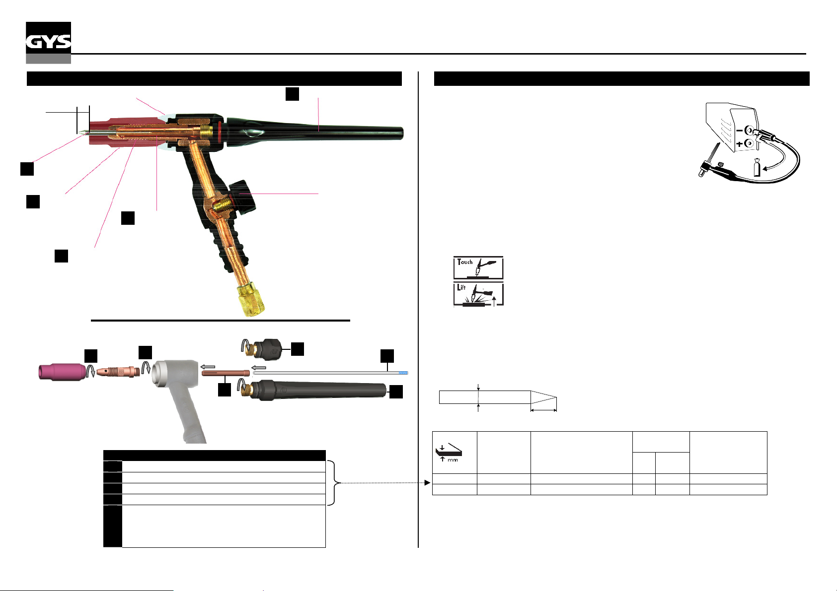
TORCHE TIG SR17V
5
5 4
ASSEMBLAGE TORCHE SR17V
5 mm
Électrode
1
tungstène
Buse gaz
2
céramique
Pince étau
4
RESPECTER L’ORDRE DE MONTAGE SUIVANT :
Support pinces
3
et buse
2
1
COMPOSITION
Electrodes tungstène WR2 (Ø 1,6 & Ø 2,4)
4
2 Buses (n° 5 & n°7)
Supports pince et buse (Ø 1,6 & Ø 2,4)
1
Pinces étau (Ø 1,6 & Ø 2,4)
3
5 Coiffes :
- courte : utilisée pour les endroits peu accessibles
(nécessite de couper l’électrode tungstène)
- longue : la plus utilisée
3
5
Coiffe
anne
SOUDAGE TIG avec torche à valve
Fonctionnement :
Le soudage TIG DC requiert une protection gazeuse (Argon).
Pour souder en TIG, suivre les étapes suivantes :
1. Connecter la pince de masse sur la polarité positive (+).
Brancher une torche « à valve » sur la polarité négative (-).
2. Raccorder le tuyau de gaz au manodétendeur de la bouteille de gaz.
Il sera parfois nécessaire de le couper avant l’écrou si ce dernier
n’est pas adapté au manodétendeur.
3. Régler l’intensité souhaitée, selon l’épaisseur à souder (30A/mm)
4. Régler le débit de gaz sur le manodétendeur de la bouteille de gaz (voir tableau suivant),
puis ouvrir la valve de la torche
5. Pour amorcer :
Pour les postes équipés de la fonction « LIFT »,
Pour les autres postes, gratter l’électrode sur la pièce à souder pour amorcer l’arc.
6. En fin de soudure : soulever la torche d'un geste rapide, ne couper le gaz qu'après
refroidissement de l'électrode.
Affutage électrode :
Pour un fonctionnement optimal vous devez affûter l’électrode tungstène de la manière suivante :
d
Combinaisons conseillées :
Courant
0,5-5 10-130 1,6 5 8 6-7
4-7 130-160 2,4 7 11 7-8
a- toucher l’électrode sur la pièce à souder.
b- relever l’électrode 2 à 5 mm de la pièce à souder pour amorcer l’arc
L = 2,5 x d
l
L
(A)
∅ Electrode
(mm)
= ∅ fil métal
d’apport)
N°
Buse
(mm)
(Argon l/mn)
∅
Débit
S129-220410
Page 2
p
e
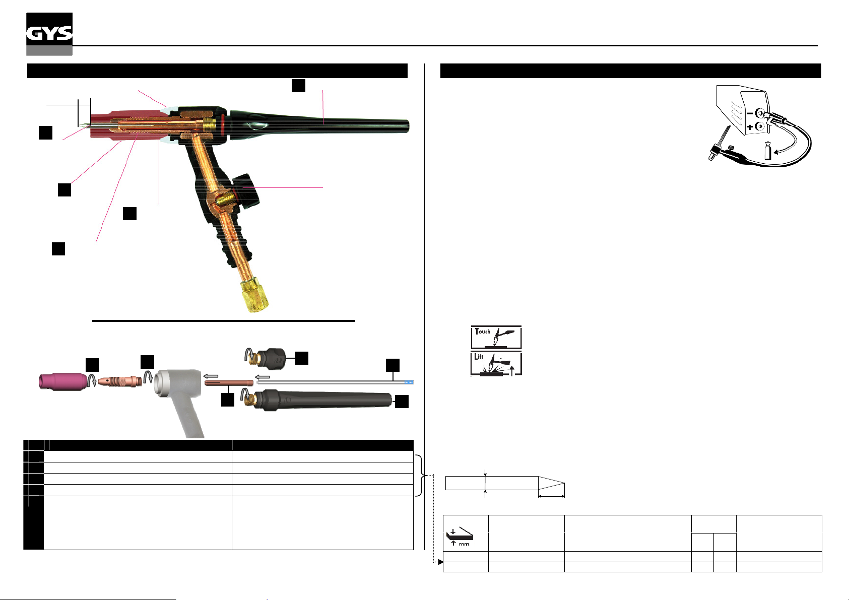
TIG TORCH SR17V / WIG BRENNER SR17V
)
5 4
TORCH SR17V ASSEMBLY / ZUSAMMENSTELLUNG DES BRENNERS SR17V
5 mm
Insulating ring /
Isolierring
1
Tungsten
Electrode
WIG
Elektrode
Ceramic gas nozzles
Keramikdüse
2
4
Collet
S
annhülse
Collet bodies
3
Spannhülsengehäuse
FOLLOW ASSEMBLY INSTRUCTIONS BELOW :
BITTE BEACHTEN SIE FOLGENDE AUFBAUANLEITUNGEN :
2
1
3
COMPOSITION AUFBAU
Tungsten electrodes WR2 (Ø 1,6 & Ø 2,4) Wolfram Elektroden WR2 (Ø 1,6 & Ø 2,4)
4
2 Ceramic nozzles (n° 5 & n°7) Keramikdüse (n° 5 & n°7)
Collet bodies (Ø 1,6 & Ø 2,4) Spannhülsengehäuse (Ø .1,6 & Ø 2,4)
1
Collet (Ø 1,6 & Ø 2,4) Spannhülse (Ø 1,6 & Ø 2,4)
3
5 Caps :
- short: used for difficult acces s locations (need
to cut the tungsten electrode)
- long : the most common used
Brennerkappe :
- Kurz : für schlecht zugängliche Stellen
benutzt (die Wolframelektrode muss gekürzt
werden)
- Lang : gängingste Variante
Cap
/
5
Brennerkapp
Valve
Ventil
5
TIG WELDING with torch with valve / WIG-Schweißen mit Ventilbrenner
Functions / Arbeitsablauf :
The TIG DC welding requires a gas protection (Argon).
Der DC WIG Schweißprozess erfordert Schutzgas (Argon)
To weld with TIG, follow the following steps:
Gehen Sie wie folgt vor :
1. Connect the earth clamp to the positive (+) terminal.
Schließen Sie das Massekabel an die (+) Schweißbuchse an.
Plug a torch with valve on the negative (-) terminal.
Schließen Sie den Ventilbrenner (Art.-Nr. 044425) an die (-) Buchse an.
2. Plug the torch gas pipe onto the gas bottle regulator.
It might be sometimes necessary to cut it before the nut if the nut is not adapted to the
regulator/flowmeter.
Schließen Sie die Brennergasleitung direkt an den Druckminderer des Gasflasche an.
Es ist manchmal notwendig diesen an der Anschluss-Mutter anzupassen.
3. .
Adjust the intensity in relation to the thickness of metal to be welded (30A/mm)
Stellen Sie den gewünschten Strom ein
Werkstückdicke
4.
Adjust the gas flow on the regula tor fitt ed to the gas cylinder (see fo llow ing tab le), then ope n
Hinweis: Als Faustregel gelten 30 A pro Millimeter
valve of the torch
Öffnen Sie das Gasmanometer der Gasflasche (siehe Tabelle unten) und erst dann öffnen Sie das
Brennergasventil.
5.
To start
/ Zünden:
For the machines with the « LIFT » mode
a-
touch down the electrode with the base me tal to be welded./
der Elektrode berühren
b-
Lift the electrode 2-5mm away from the metal to b e w e ld ed to start the arc
Brenner hochheben 2 bis 5 mm über das Werkstück
For the other machines, scratch the electrode on the part to weld to start the arc.
/ Für Geräte mit « Lift » Funktion :
Das Werkstück mit
.
Für Geräte ohne « Lift Arc» Funktion die Wolframelektrode am Werkstück anstreichen bis
der Lichtbogen zündet
6.
At the end of welding: quickly lift the torch, stop the gas only, whilst the electrode cooling/.
Nach dem
abdrehen.
Electrode grinding/ Eletrodenspitzen :
For optimum functioning the tungsten electrode must be sharpened in the following way
Schweißen : Brenner rasch anheben und das Gas erst nach Abkühlung der Elektrode
Für ein optimale Schweißnaht, sollten Sie d ie Wolfr am e lek trod e f olgendermaßen anschleifen :
d
l
L
L = 2,5 x d
Advised combinations / Parameter :
0,5-5 10-130 1,6 5 8 6-7
4-7 130-160 2,4 7 11 7-8
Intensity
(A)
Schweiß-strom (A)
∅ Electrode (mm)
= ∅ TIG wire
∅ Elektrode (mm)
= ∅ des zu zu führenden Metalles
Contact tip
/Düse
∅
N°
(mm
Flow (Argon Lpm)
Gasfluss
(Argon l/mn)
the
 Loading...