

Page 1
FR
2-21
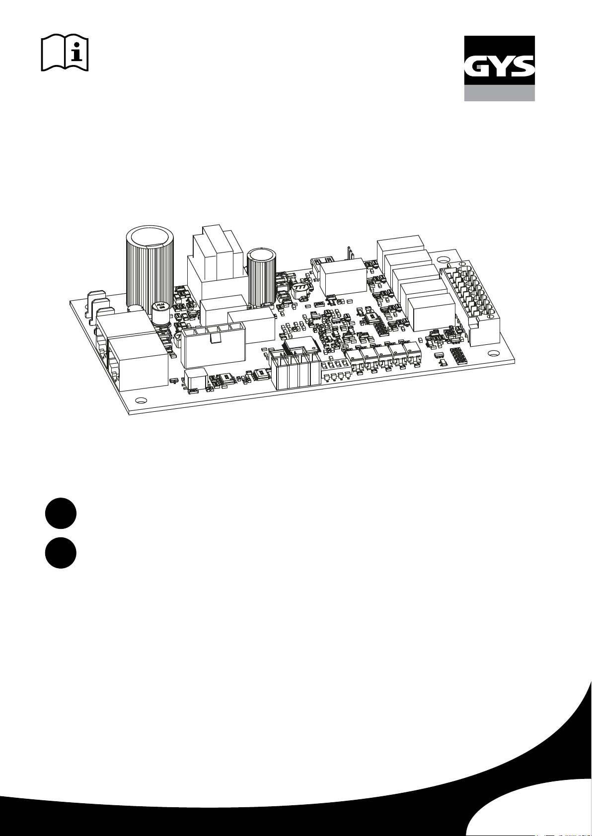
SAM-1A
EN
73502_V3.2_26/12/2024
22-40
www.gys.fr
Page 2
SAM-1A
1. GÉNÉRALITÉS
RÉVISION
Révision Date Modication
1.0 01/04/2022 Création
2.0 27/02/2023 Modication
3.0 05/09/2023 Modication
3.1 27/11/2023 Modication
3.2 25/06/2024 Modication
2. AVERTISSEMENTS - RÈGLES DE SÉCURITÉ
CONSIGNE GÉNÉRALE
Ce manuel d’utilisation comprend des indications sur le fonctionnement de l’appareil et les précautions à suivre
pour la sécurité de l’utilisateur.
Merci de le lire attentivement avant la première utilisation et de le conserver soigneusement pour toute
relecture future.
Ces instructions doivent être lues et bien comprises avant toute opération.
Toute modication ou maintenance non indiquée dans le manuel ne doit pas être entreprise.
Tout dommage corporel ou matériel dû à une utilisation non-conforme aux instructions de ce manuel ne pourra
être retenu à la charge du fabricant.
En cas de problème ou d’incertitude, veuillez consulter une personne qualiée pour manier correctement
l’appareil.
Cet appareil doit être utilisé uniquement pour faire de l’impression de ticket et/ou de la transmission de donnée
dans les limites indiquées sur l’appareil et le manuel. Il faut respecter les instructions relatives à la sécurité. En
cas d’utilisation inadéquate ou dangereuse, le fabricant ne pourra être tenu responsable.
FR
Appareil destiné à un usage à l’intérieur. Il ne doit pas être exposé à la pluie.
Règlementation :
Appareil conforme aux directives européennes. La déclaration de conformité est disponible sur notre site
internet (voir à la page de couverture).
Matériel conforme aux exigences britanniques. La déclaration de conformité britannique est disponible sur
notre site (voir à la page de couverture).
Ce matériel faisant l’objet d’une collecte sélective selon la directive européenne 2012/19/UE. Ne pas jeter
dans une poubelle domestique !
Produit recyclable qui relève d’une consigne de tri.
SÉCURITÉ ÉLECTRIQUE
Lors de toute intervention sur le produit, veiller à sécuriser la zone en tenant à distance toute personne n’ayant pas pris connaissance
des consignes de sécurité décrites dans cette notice. Ce produit doit de préférence être installé par un professionnel dans les
règles d’installation en vigueur dans le pays. Dans le cas contraire, il est recommandé de prendre connaissance de ces règles avant
intervention.
PRÉCAUTIONS CONTRE LES DOMMAGES ÉLECTROSTATIQUES
L’électricité statique peut endommager les équipements électroniques. Utilisez un bracelet antistatique relié à la terre,
une sangle de cheville ou un dispositif de sécurité équivalent pour éviter tout dommage électrostatique (ESD) lorsque
vous eectuez l’installation de ce produit.
Les dommages électrostatiques peuvent irrémédiablement endommager le générateur et/ou le produit. Pour protéger les composants
électroniques de dommages électrostatiques, placez ce produit sur une surface antistatique, telle qu’un tapis de décharge antistatique,
un sachet antistatique ou un tapis antistatique jetable.
2
Page 3
SAM-1A
FR
3. PRÉSENTATION DU PRODUIT
INTRODUCTION
Ce document décrit la mise en service et le raccordement de la passerelle SAM-1A au sein d’un réseau d’automate ou robot.
Le Smart Automation Module (SAM-1A) est une solution de communication entre les générateurs de soudage GYS compatibles et les
automates/robots.
SAM-1A convertit le langage de communication interne des machines GYS en signaux d’entrées / sorties numériques (TOR) et analogiques.
L’ensemble générateur/SAM-1A peut être réaecté à un nouveau système sans modication de celui-ci (intégration dans une nouvelle
machine, remplacement d’un automate ou robot, automatisation d’un procédé, etc…).
PRÉSENTATION
Le SAM-1A (réf. 071940) autorise une application supplémentaire sur les générateurs compatibles.
Le module permet d’accéder à des paramètres du générateur de soudage permettant un contrôle par l’automate ou le robot.
Les produits compatibles sont les suivants :
Procédé de soudage Désignation Référence
NEOPULSE 320 C 062474
NEOPULSE 400 CW 062061
MIG/MAG
TIG
PULSEMIG 400 CW 062658
NEOPULSE 400 G 014497
NEOPULSE 500 G 014503
EXAGON 400 FLEX CV 069718
KRYPTON 231 DC FV 075245
KRYPTON 321 DC 068094
TITAN 400 DC 013520
KRYPTON 401 DC 080904
TITANIUM 230 AC/DC FV 061996
TITANIUM 321 AC/DC 069879
TITANIUM 400 AC/DC 013568
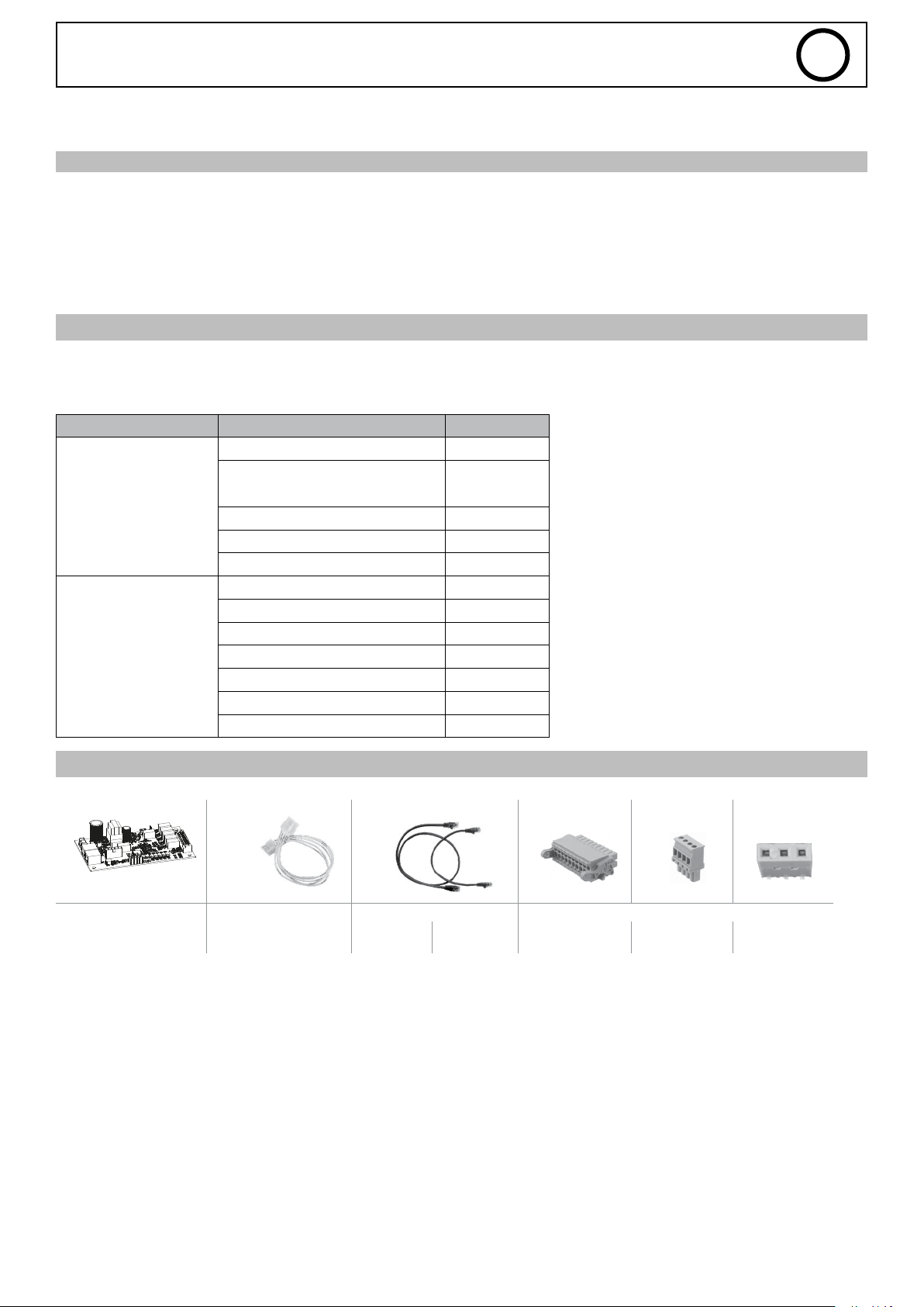
CONTENU / PIÈCES DÉTACHÉES
Carte électronique
E0101C
Faisceaux 300 mm Câbles RJ45 Connecteurs
F0035
300 mm
21574
750 mm
21575
20 points
63851
4 points
53115
Strap 3 points
3
Page 4
SAM-1A
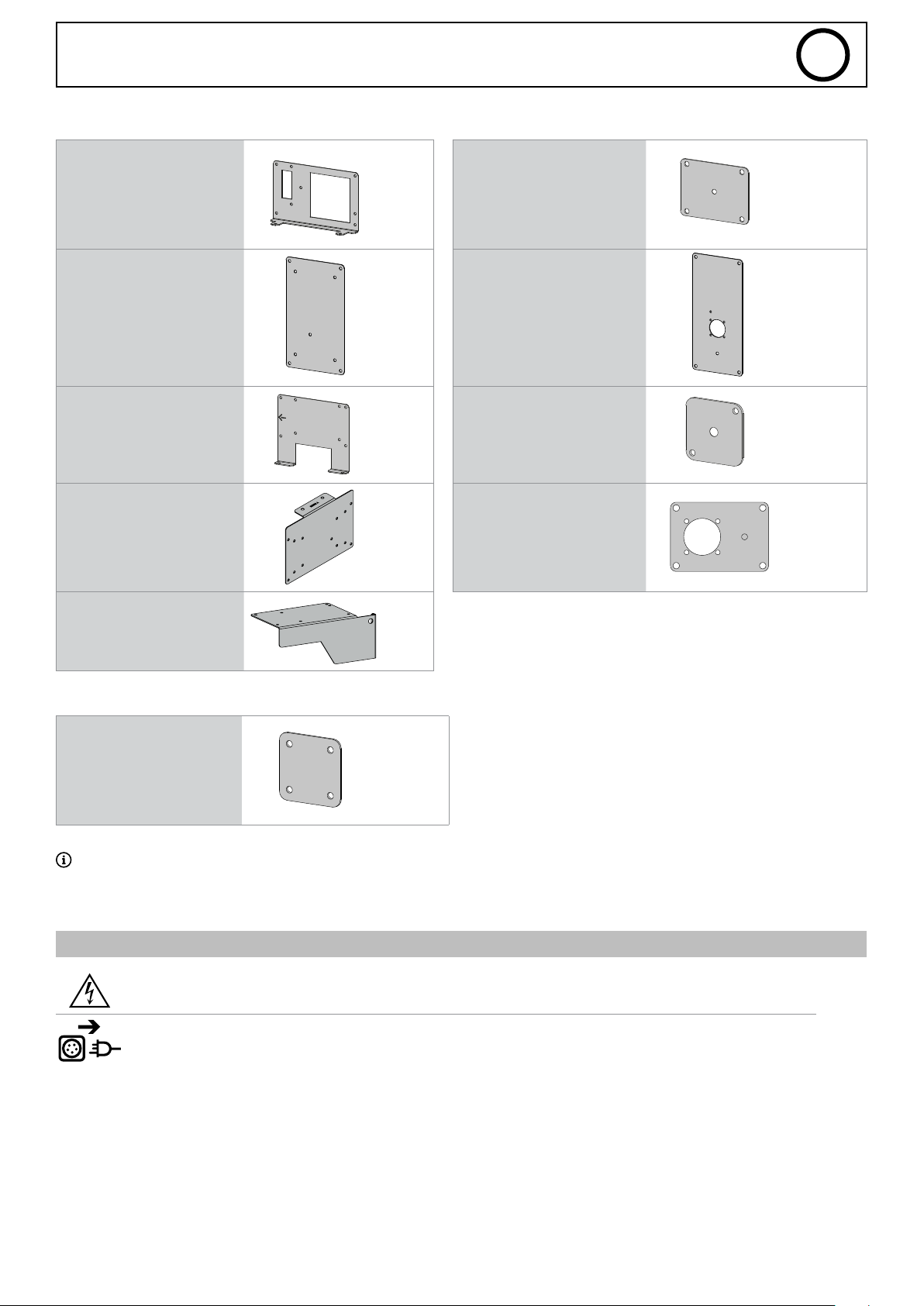
Équerres support carte électronique : Plaques support connecteur :
NEOPULSE 320 C / 400 CW 98129
NEOPULSE 400 G / 500 G K0539Z NEOPULSE 400 G / 500 G K0536GF4
KRYPTON 231 DC FV
KRYPTON 321/401 DC
TITAN 400
TITANIUM 400 AC/DC
TITANIUM 321 AC/DC
98116
NEOPULSE 320 C / 400 CW
EXAGON 400 FLEX
TITAN 400
TITANIUM 400
FR
K0535GF
K0537GF
EXAGON 400 FLEX
TITANIUM 230 AC/DC K0402
Plaque cache connecteur :
KRYPTON 231 DC FV
KRYPTON 321/401 DC
TITANIUM 230 AC/DC
TITANIUM 321 AC/DC
NEOPULSE 400 G / 500 G
Certaines congurations ne nécessitent pas tous les éléments du Kit.
K0538
99089GF
4. INSTALLATION DU PRODUIT
INSTALLATION
KRYPTON 231 DC FV
KRYPTON 321/401 DC
TITANIUM 230 AC/DC
TITANIUM 321 AC/DC
K1146GF
Installation du kit :
EXAGON / NEOPULSE /
TITAN / TITANIUM 400
4
AVERTISSEMENT
LES CHOCS ÉLECTRIQUES PEUVENT ÊTRE FATALS
Seul le personnel expérimenté et habilité par le fabricant peut eectuer l’installation. Pendant l’installation,
s’assurer que le générateur est déconnecté du réseau.
TITANIUM 230
AC/DC
TITANIUM 321
AC/DC
KRYPTON 401
DC
Page 5
SAM-1A
Tout accès aux zones internes, au-delà des zones décrites dans la présente notice, sont à proscrire et annulent la garantie et toute
autre forme de prise en charge. En eet, ces manipulations peuvent être dommageables aux parties et/ou aux composants électroniques internes du générateur.
FR
FONCTION SWO (SAFE WELDING OFF)
La fonction « Safe Welding O » permet principalement d’empêcher le générateur de courant ou de tension de démarrer. Il agit
directement sur la puissance du générateur en un temps très court.
La fonction sert également à arrêter le générateur en toute sécurité en cas d’arrêt d’urgence. Cela évite d’interrompre brutalement
l’alimentation du générateur en cas de problème. Il ne faut pas oublier qu’une rupture de l’alimentation en aval du générateur en
charge est dangereuse et peut endommager l’équipement.
I. Sécurité électrique
La fonction « Safe Welding O » n’ore pas d’isolation électrique c’est pourquoi avant une intervention sur le générateur, il doit
impérativement être isolé électriquement en coupant l’alimentation et en isolant localement le générateur (procédure de verrouillage par cadenas).
II. Activation et câblage du SWO
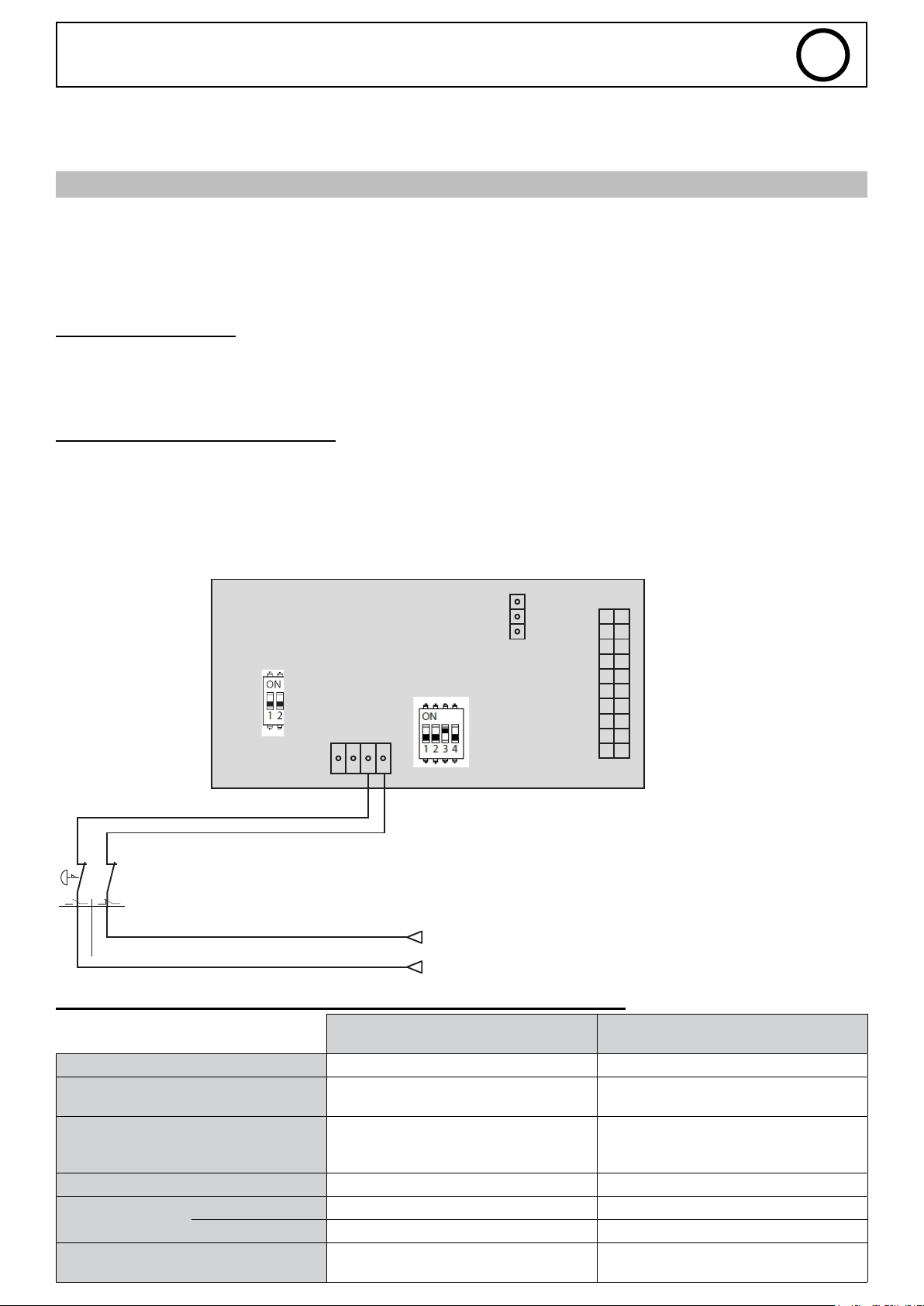
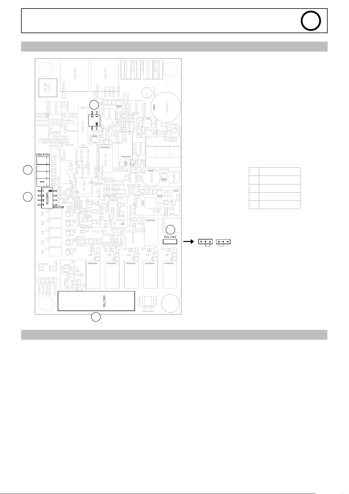
Deux interrupteurs (DIP 1 et DIP2), situés sur la carte du SAM-1A (voir carte électronique en page 11), sont prévus an de paramétrer
la fonction de sécurité et les diérentes fonctionnalités de la carte SAM-1A.
An d’activer la fonction de sécurité, il sut de basculer les 2 switch du DIP 1 sur ON et le switch 3 du DIP2 sur ON.
Dans ce cas, il est nécessaire de câbler la sécurité. Un bornier (X5) est disponible sur la carte électronique du SAM-1A (voir carte
électronique en page 11).
Schéma de principe :
CN11T02
CON10T02
A1 A2
CN11T01
EMERGENCY
STOP
1-D2
0V
Alimentation
Power supply
24Vdc
III. Caractéristiques électriques des Entrées/Sorties du bornier X5
SORTIE
(retour d’information)
Type d’isolation Contact sec Relais
Connexion
Plage de tension 20 à 30 VDC
Courant nominal à 24 VDC Max 2A 10 mA
Temps de réponse
Train d’impulsion de test
< à 1 ms à fréquence inférieure à 100 Hz
à tension nominale
temps maximal
3- S13 contact NO
4- S14 Vcc
Tension maximale à l’état bas pour 3 V
8 ms 4 ms
16 ms 8 ms
Aucune réaction Aucune réaction
ENTRÉE
1- AU_A2 : Masse
2- AU_A2 : Vcc
20 à 30 VDC
Seuil logique 15 VDC
5
Page 6
SAM-1A
5. AFFECTATION DES ENTRÉES/SORTIES
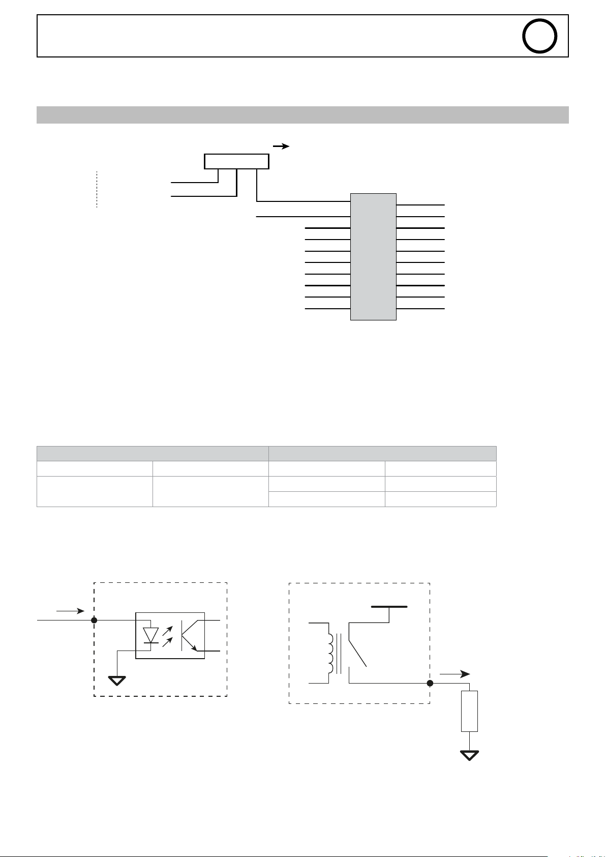
CARACTÉRISTIQUES TECHNIQUES CONNECTEUR X20
FR
POWER
24V
internal 24Vdc
common
Alimentation
3
MASSE
WELDING_PROCESS MAIN_CURRENT
AUTHORISED_START
M_WELD_VOLTAGE
2
1
INPUT_3
INPUT_4
INPUT_2
INPUT_1
voir informations page 6 et 11
EXTERNAL 24Vdc
ERROR
X20
10
11
9
12
8
13
7
14
6
15
5
16
4
17
3
18
2
19
1 20
ALIM_LIMIT_+10V
RESERVED_2
ARC_DETECT
M_WELD_CURRENT
WIRE_FEED
RESERVED_1
MMI_LOCK
START_PROCESS
START_GAZ
• Alimentation
Les entrées/sorties (24 V) peuvent être alimentées soit en interne SAM-1A soit par une alimentation externe 24 V.
Le SAM-1A est conguré de série pour une alimentation en interne.
Pour utiliser une alimentation externe, il sut de basculer le strap du connecteur 3 points d’alimentation (voir carte électronique en
page 11) et d’appliquer 24 V sur le connecteur X20 (pin 10).
Un strap 3 points est livré avec le produit (sachet lerie et connecteurs) permettant d’utiliser l’alimentation interne et de la diriger
vers l’extérieur du produit.
Alimentation interne Alimentation 24V externe
Tension nominale Courant nominal Tension maximale Courant maximal
24 V 100 mA
24 V 2 A
10 V 20 mA
• Entrées/Sorties digitales
Entrées digitales Sorties digitales
Electronic card SAM-1A
10 mA
Electronic card SAM-1A
+24 V
2 A
L
O
A
D
6
Page 7
SAM-1A
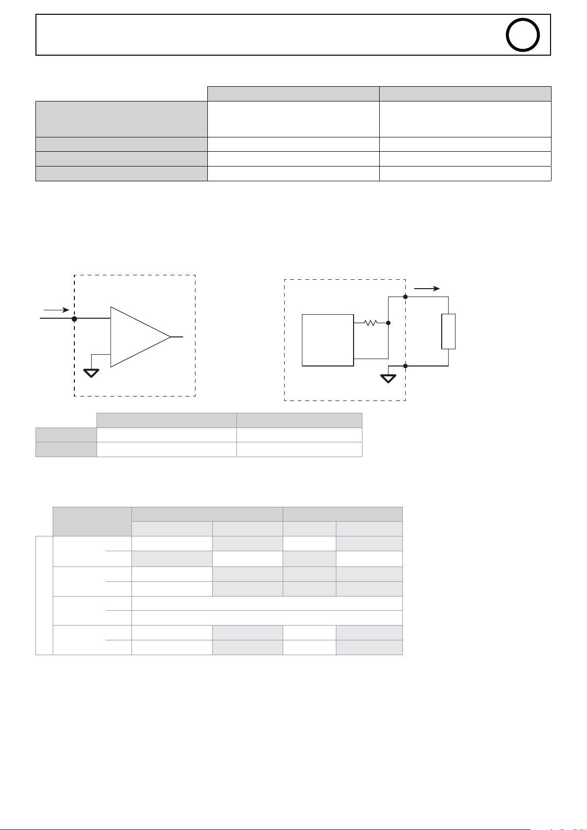
Récapitulatif et caractéristiques techniques des entrées et sorties TOR SAM :
Sortie Entrée
Contact SEC 24V DC
Type isolation
ON Voltage Vmin/Vmax +20 V à +30 V 15 VDC - 28 VDC
OFF Voltage Vmin/Vmax 0 VDC - 5 VDC
Courant nominal à +24 V Max 2A 5 mA
1 - 24 VDC
2-5 - DO1 – DO4 (NO)
• Entrées/Sorties analogiques
Entrées analogiques Sorties analogiques
Photocoupleur isolation 500 VDC
6-9 - DI1 – DI4 (NO)
10 - Masse (0 V)
FR
Electronic card SAM-1A
10 mA
+
1
-
Sortie Entrée
Tension 0 - 10 V 0 - 10 V
Courant 100 µA 1 mA
• Paramétrage du DIP 2
Description
SWITCH-1
SWITCH-2
SWITCH-3
DIP Switch
SWITCH-4
JOB Manuel JOB CC Tracking
OFF Mode JOB Mode JOB
ON Mode Manuel Mode Tracking
ON Weld_Current
OFF Wire_Speed
OFF Safety désactivée
ON Safety activée
OFF Job Lock Job Lock
ON Job Unlock Job Unlock
MIG TIG
Electronic card SAM-1A
DAC
0-10 V
100 μA
L
O
A
D
7
Page 8
Welding Process
DELTA
SAM
CPU
CPU
CPU
CPU
SAM
SAM
Emitter
Process Control (1)
FOR TIG AC/DC
Authorised_Start
Welding Trigger_CMD
Welding Process
Function
Setting Values
0,1s
Authorised Start
Function
Start Gas
Welding Current
Welding Process
SAM
CPU
CPU
Emitter
SAM
100A
200A
Average cycle Current
Function
Start Process
Welding Process
GAS ON
Arc detect
Main Current
SAM
CPU
Emitter
SAM
SAM
SAM
Pregas Start Upslope Welding Downslope Stop Post-gas
73.1
90
71
2.1
3.0
73.1
Process Control (1)
FOR TIG AC/DC
JOB number
Authorised_Start
Welding Trigger_CMD
Welding Process
DELTA
CPU
CPU
CPU
CPU
SAM
SAM
Emitter
Function
0,1s
0,1s
CPU
CPU
CPU
CPU
SAM
SAM
Emitter
Process Control (1)
FOR TIG AC/DC
Authorised_Start
Welding Trigger_CMD
Welding Process
Function
Setting Values
0,1s
71
72
2.1
3.0
73.1
90
71
2.1
3.0
73.1
PARAM
Process Control (1)
FOR TIG AC/DC
JOB number
Authorised_Start
Welding Trigger_CMD
Welding Process
DELTA
CPU
CPU
CPU
CPU
SAM
SAM
Emitter
Function
0,1s
0,1s
CPU
CPU
CPU
CPU
SAM
SAM
Emitter
Process Control (1)
FOR TIG AC/DC
Authorised_Start
Welding Trigger_CMD
Welding Process
Function
Setting Values
0,1s
Authorised Start
Function
Start Gas
Welding Current
Welding Process
SAM
CPU
CPU
Emitter
SAM
100A
200A
71
72
2.1
3.0
73.1
90
71
2.1
3.0
73.1
PARAM
SAM-1A
FR
6. PROCÉDÉS DE SOUDURE
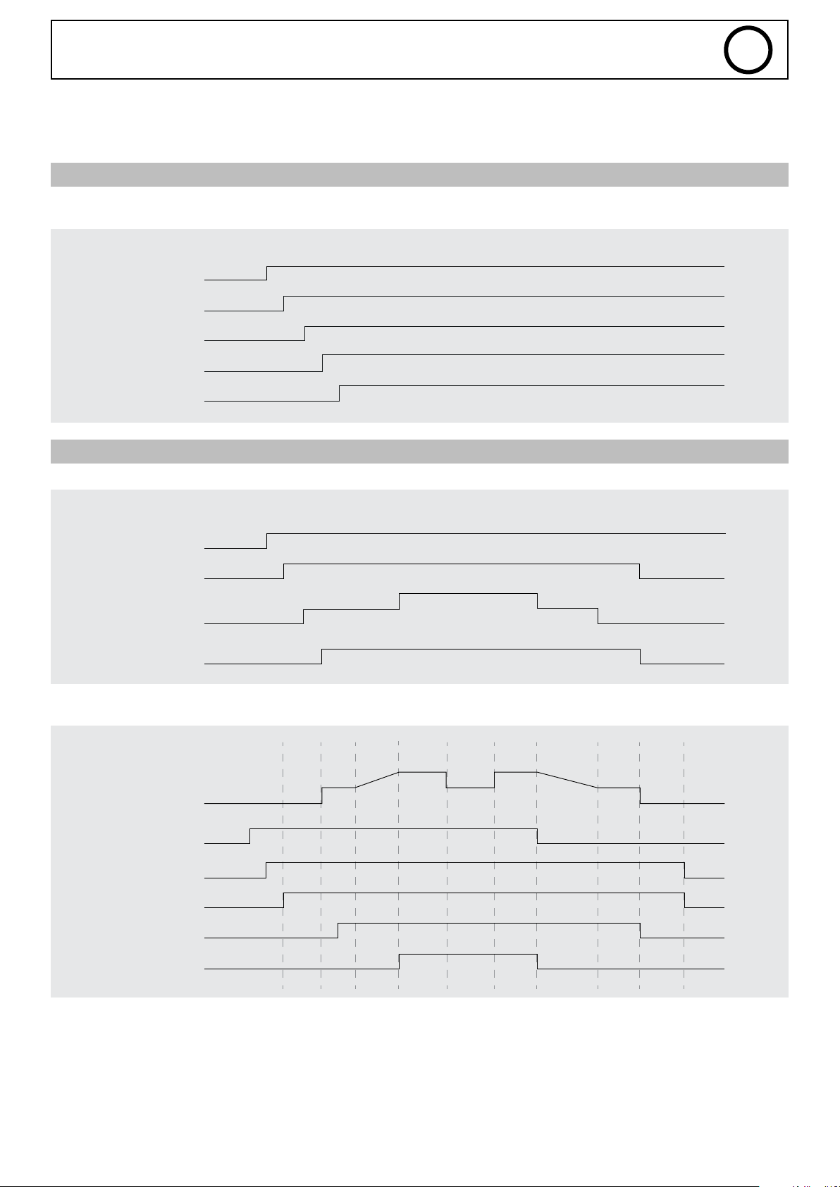
Ce chapitre fournit les diagrammes de diérents procédés de soudage.
A) DIAGRAMME D’UN CYCLE DE SOUDURE
Function
FOR TIG AC/DC
JOB number
Authorised Start
Start Process
Welding Process
B) DIAGRAMME D’UN CYCLE DE SOUDURE EN MODE TRACKING
Function
Authorised Start
Start Gas
Welding Current
0,1s
100A
Job Mode init
Tracking Mode TIG
200A
Emitter
CPU
CPU
SAM
CPU
SAM
Emitter
SAM
CPU
CPU
Welding Process
Function
Average cycle Current
Start Process
Welding Process
GAS ON
Arc detect
Main Current
Welding cycle
Pregas Start Upslope Welding Downslope Stop Post-gas
SAM
Emitter
CPU
SAM
SAM
SAM
SAM
8
Page 9
Start Process
Welding Process
GAS ON
Arc detect
Main Current
SAM
CPU
SAM
SAM
SAM
Function
FOR TIG AC/DC
JOB number
Authorised Start
Start Process
Welding Process
SAM
CPU
CPU
CPU
SAM
Emitter
0,1s
Function
Process Control (1)
TIG_Type (TIG AC/DC)
User Setting
Authorised_Start
Welding Simuler
Welding Trigger_CMD
Welding Process
0,1s
CPU
Emitter
CPU
CPU
CPU
CPU
SAM
SAM
Function
Recovery_Weld
Arc detect
Arc initiate
CPU
Emitter
SAM
Arc
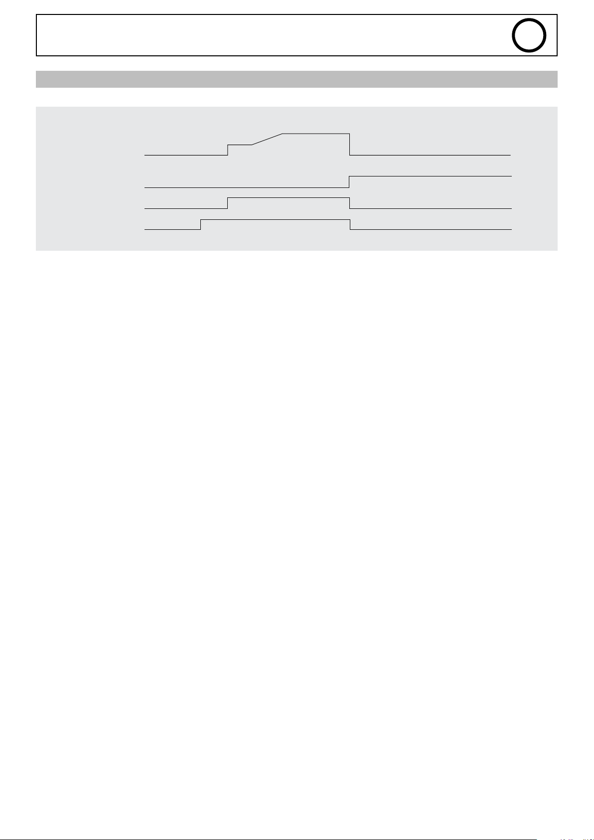
C) DIAGRAMME EN CAS D’ERREUR
Function
Average cycle Current
Error state
Authorised Start
Gas ON
SAM-1A
Error
Welding Downslope Stop
Post-gas
FR
Emitter
SAM
SAM
SAM
SAM
9
Page 10
SAM-1A
FR
7. MAINTENANCE
MISE À JOUR
Avant la première utilisation du produit, il est conseillé de vérier la présence de nouvelle mise à jour «Logiciel» sur le site SAV GYS
(code client nécessaire).
Une seule mise à jour permet de mettre à jour tous les produits connectés (générateur, commande déportée, dévidoir,
SAM, etc)
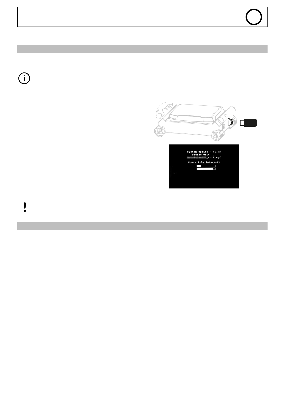
1- Déconnecter du réseau tous les appareils.
2- Insérer une clé USB contenant les dernières mises à jour
dans un port dédié puis démarrer l’appareil.
3- L’écran apparait si une nouvelle version est détectée.
Attendre jusqu’à la n de l’étape et redémarrer le produit
après avoir déconnecté la clé USB.
Avant d’eectuer une mise à jour, prendre connaissance des modications apportées par le nouveau rmware. Dans le cas d’un changement de version majeur, des modications pourraient
être à apporter au programme de l’automate/robot.
LISTE DES DÉFAUTS
Se référer à la partie SAV du site internet www.gys.fr.
10
Page 11
CARTE ÉLECTRONIQUE
SAM-1A
5
FR
4
3
1
CONDITIONS DE GARANTIE FRANCE
1 X20
2 Alimentation
3 DIP 2
4 X5
5 DIP 1
2
Internal
External
La garantie couvre tous défauts ou vices de fabrication pendant 2 ans, à compter de la date d’achat (pièces et main-d’œuvre).
La garantie ne couvre pas :
• Toutes autres avaries dues au transport.
• L’usure normale des pièces (Ex. : câbles, pinces, etc.).
• Les incidents dus à un mauvais usage (erreur d’alimentation, chute, démontage).
• Les pannes liées à l’environnement (pollution, rouille, poussière).
En cas de panne, retourner l’appareil à votre distributeur, en y joignant :
- un justicatif d’achat daté (ticket de sortie de caisse, facture….)
- une note explicative de la panne.
11
Page 12
SAM-1A
FR
ANNEXE 1 - RÉGLAGES DU SAM-1A AVEC NEOPULSE/PULSEMIG
1. Entrées/Sorties digitales pour NEOPULSE/PULSEMIG ....................................................................................12
a) Entrées digitales .................................................................................................................................................................12
b) Sorties digitales .................................................................................................................................................................. 12
2. Entrées/Sorties analogiques pour NEOPULSE/PULSEMIG ............................................................................. 12
a) Sorties analogiques ............................................................................................................................................................12
b) Fonctions des entrées analogiques ......................................................................................................................................13
I. Mode JOB – Sans réglages ........................................................................................................................................... 13
II. Mode JOB – Réglages courant ...................................................................................................................................... 13
III. Mode JOB – Réglages vitesse l ................................................................................................................................... 13
IV. Mode MANUEL ............................................................................................................................................................14
3. Où trouver le numéro du JOB ......................................................................................................................................14
4. Où trouver les valeurs des synergies .......................................................................................................................15
5. Comment changer le mode de gestion pour trouver les valeurs min/max ............................................. 15
6. Exemple de schéma ..........................................................................................................................................................15
1. Entrées/Sorties digitales pour NEOPULSE/PULSEMIG
a) Entrées digitales
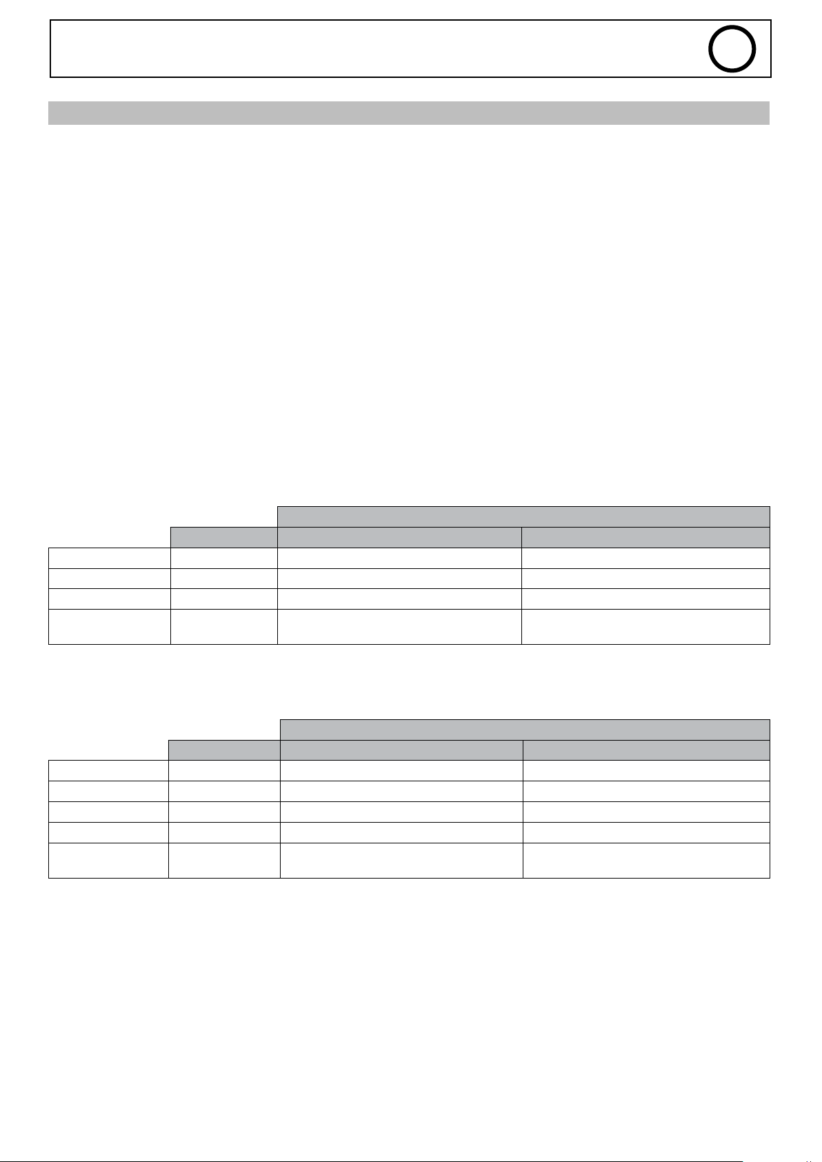
Le SAM-1A possède 4 entrées digitales TOR détaillées ci-dessous :
État
Connecteur-Pin 0 1
MMI_LOCK X20-18 Mode multimètre Courant-Tension Accès aux réglages du générateur
Start_Process X20-19 Arrêter la soudure Lancer le cycle de soudure
Start_Gaz X20-20 Electrovanne GAZ fermée Electrovanne GAZ ouverte
Wire_Feed
(Only in MIG)
b) Sorties Digitales
Ainsi que les 4 sorties digitales TOR suivantes :
Error X20-6 Pas d’erreur Erreur détectée
Authorised_Start X20-7 Soudure interdite Autorisé à souder
Arc_Detect X20-14 Arc non détecté Détection d’un arc
Welding_Process X20-8 Pas de soudure en cours Soudure en cours
Main_Current X20-13
X20-16 Fil arrêté Dévider le l
État
Connecteur-Pin 0 1
En dehors de la phase principale de
soudure
Dans la phase principale de soudure
2. Entrées/Sorties analogiques pour NEOPULSE/PULSEMIG
a) Sorties analogiques
Le SAM-1A possède deux sorties analogiques remontant les informations de mesure de tension et courant suivant les
caractéristiques :
Mesure Tension (M_Weld_Voltage, X20-5) => varie de 0 V à 10 V, correspond à une plage de mesure de 0 V à 50 V
Mesure Courant (M_Weld_Current, X20-15) => varie de 0 V à 10 V, correspond à une plage de mesure de 0 A à 500 A
12
Page 13
SAM-1A
b) Fonctions des entrées analogiques
I. Mode JOB – Sans réglages
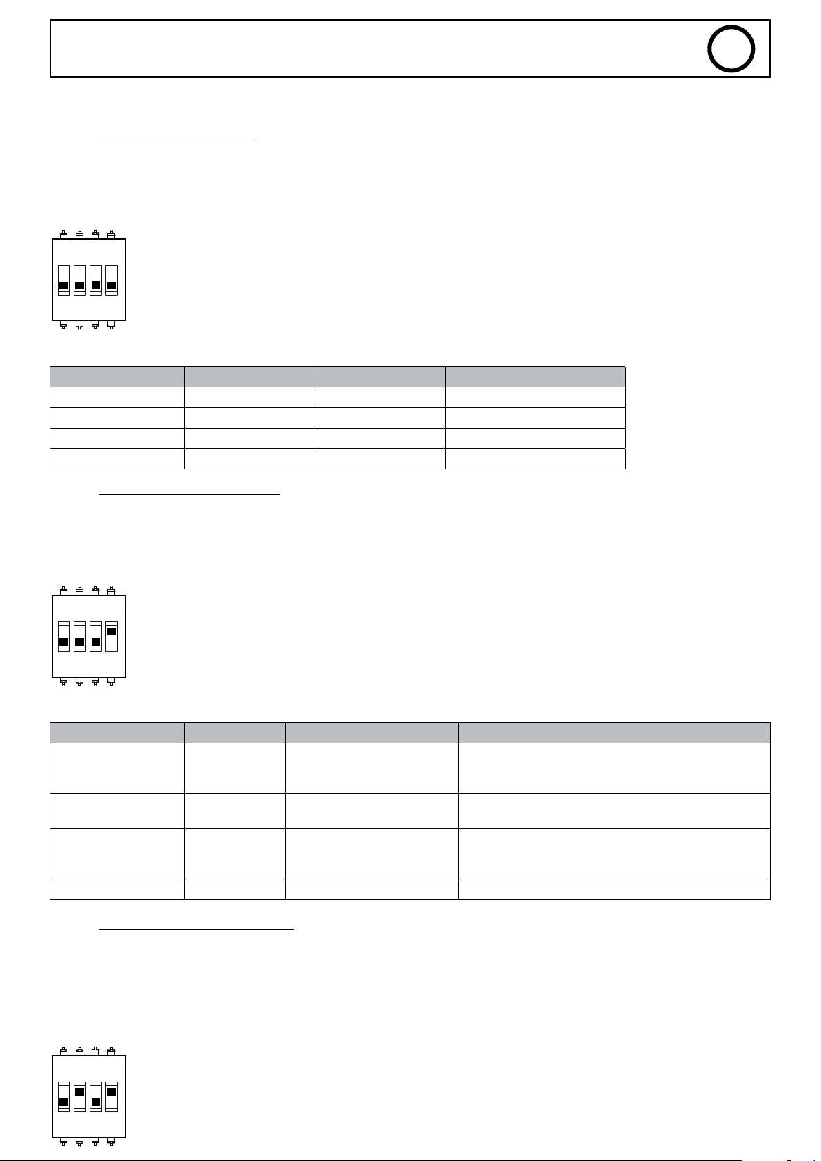
Tous les paramètres enregistrés dans le JOB sont utilisés (les valeurs sur les entrées 1, 2 et 3 ne sont donc pas prises en compte)
DIP2-SWITCH 1 = OFF (Mode : JOB)
DIP2-SWITCH 2 = OFF
DIP2-SWITCH 4= OFF (JOB LOCK)
FR
1 2ON3 4
Tableau des valeurs réglables :
Entrée SAM-1A Connecteur-Pin Paramètre Valeur
INPUT_1 X20-1 - -
INPUT_2 X20-2 - -
INPUT_3 X20-4 - -
INPUT_4 X20-3 Numéro de JOB de 1 à 20
II. Mode JOB – Réglages courant
Les valeurs des paramètres Arc_LEN, Self et Weld_Current du JOB sont ignorées (les valeurs sont prises sur les entrées du SAM-1A)
DIP2-SWITCH 1 = OFF (Mode : JOB)
DIP2-SWITCH 2 = OFF (Gestion : Courant)
DIP2-SWITCH 4 = ON (JOB UNLOCK)
1 2ON3 4
Tableau des valeurs réglables :
Entrée SAM-1A Connecteur-Pin Paramètre Valeur
0 V = -6
INPUT_1 X20-1 ARC_LEN
INPUT_2 X20-2 WELD_CURRENT
INPUT_3 X20-4 SELF
INPUT_4 X20-3 Numéro de JOB de 0 à 20
0 V = valeur mini de la synergie
10 V = valeur max de la synergie
5 V = 0
10 V = +6
0 V = -4
5 V = 0
10 V = +4
III. Mode JOB – Réglages vitesse l
Les valeurs des paramètres Arc_LEN, Self et Wire_Weld_Speed du JOB sont ignorées (les valeurs sont prises sur les entrées du SAM1A)
DIP2-SWITCH 1 = OFF (Mode : JOB)
DIP2-SWITCH 2 = ON (Gestion : Vitesse l)
DIP2-SWITCH 4 = ON (JOB UNLOCK)
1 2ON3 4
13
Page 14
SAM-1A
Tableau des valeurs réglables :
Entrée SAM-1A Connecteur-Pin Paramètre Valeur
INPUT_1 X20-1 ARC_LEN
INPUT_2 X20-2 WIRE_WELD_SPEED
INPUT_3 X20-4 SELF
INPUT_4 X20-3 Numéro de JOB de 0 à 20
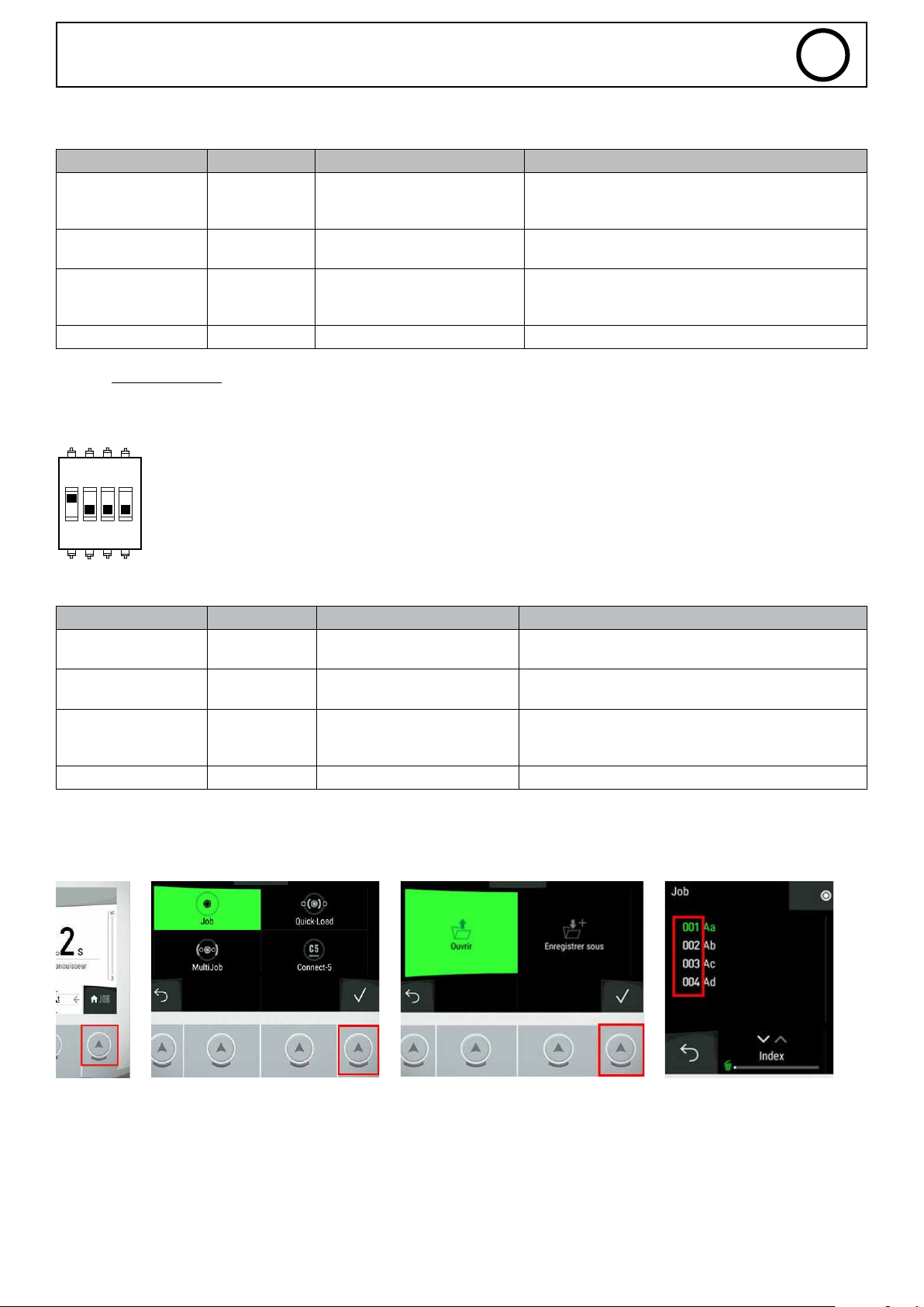
IV. Mode MANUEL
DIP2-SWITCH 1 = ON (Mode : MANUEL)
0 V = valeur mini de la synergie
10 V = valeur max de la synergie
FR
0 V = -6
5 V = 0
10 V = +6
0 V = -4
5 V = 0
10 V = +4
1 2ON3 4
Tableau des valeurs réglables :
Entrée SAM-1A Connecteur-Pin Paramètre Valeur
INPUT_1 X20-1 WELD_VOLTAGE
INPUT_2 X20-2 WIRE_WELD_SPEED
INPUT_3 X20-4 SELF
INPUT_4 X20-3 - -
0 V = valeur mini de la synergie
10 V = valeur max de la synergie
3. Où trouver le numéro du JOB ?
Sur la MMI du produit, suivre les étapes suivantes :
1 2 3 4
0 V = 0 V
10 V = 50 V
0 V = -4
5 V = 0
10 V = +4
14
Page 15
SAM-1A
1 =
SOUDURE EN COURS
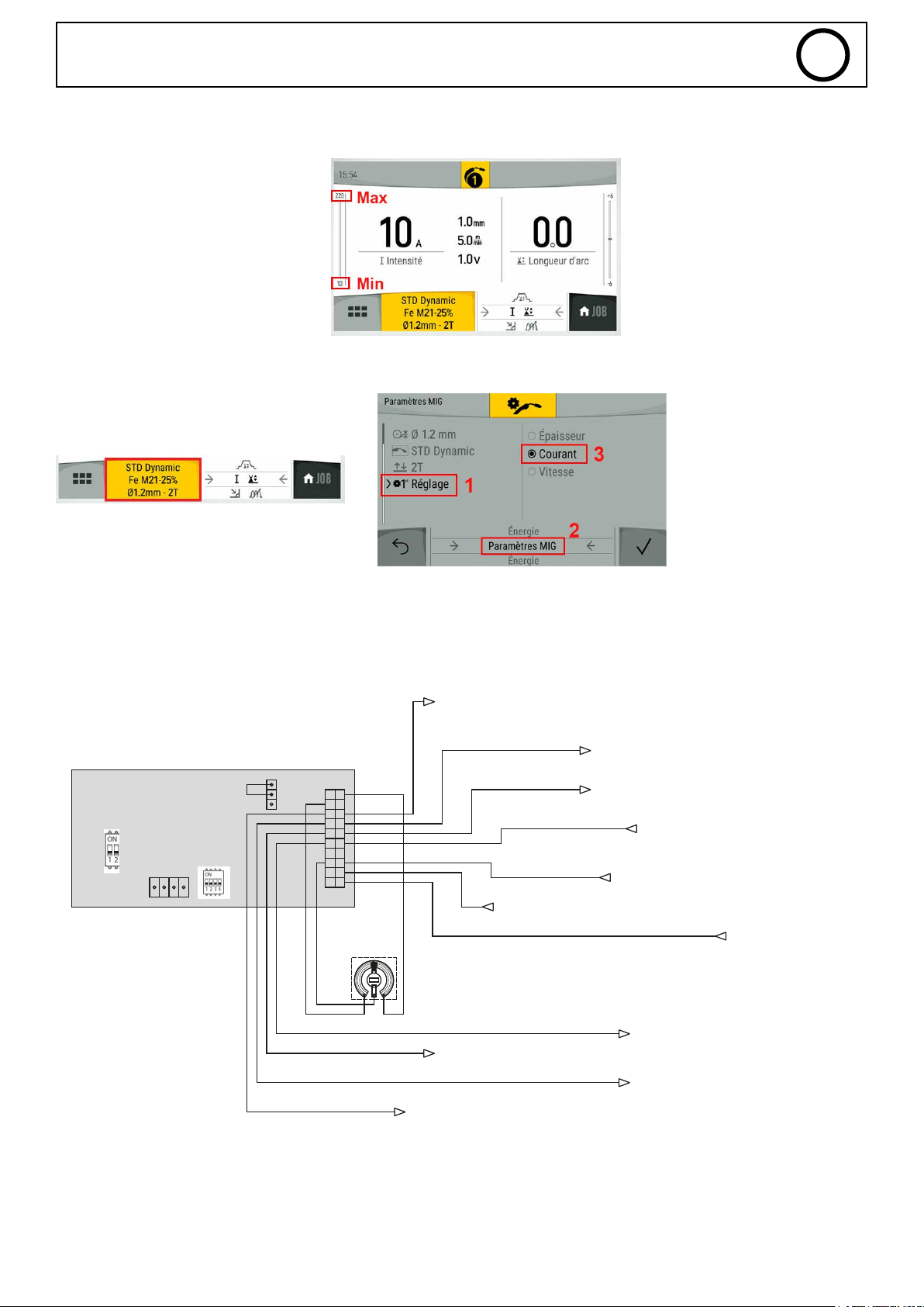
4. Où trouver les valeurs des synergies ?
Depuis la MMI du produit, les valeurs
synergiques MIN et MAX sont indiquées
sur le curseur à gauche.
5. Comment changer le mode de gestion pour trouver les valeurs min/max ?
Depuis le menu du JOB sur la MMI du produit
FR
6. Exemple de schéma
MIG - MODE JOB - SANS RÉGLAGES - SAFETY DÉSACTIVÉE - ALIM 24V INTERNE
CN11T02
CON10T02
CN11T01
3-IN PUT_4
10K
Réglage numéro de JOB
0V =
0.5V = JOB 1
10V = JOB 20
8-WELDING _PROCESS
13-MAIN_ CURRENT
0 =
1 =
19-START_PROCESS
pas de JOB
6-ERROR (0=OK / 1=ERREUR)
0 =
PAS DE SOUDURE
En dehors de la phase principale de soudure
Dans la phase principale de soudure
14-ARC_DETECT (0=PAS D ARC / 1=ARD DETECTE)
15-M_WELD_CURRENT
18-MMI_LOCK
0V = 0A
10V = 500A
16-WIRE_F EED (0=STOP / 1=START)
0 =
LOCK (mode multimètre)
UNLOCK (réglages générateur)
1 =
0 = STOP
1 = START
20-START_GAS
0V = 0V
10V = 50V
0 =
SOUDURE INTERDITE
SOUDURE AUTORISÉE
1 =
0 =
1 =
OK
5-M_WELD_VOLTAGE
ERREUR
7-AUTHO RISED_ START
PAS D’ARC
0 =
ARC DÉTECTÉ
1 =
0 =
DÉVIDAGE OFF
DÉVIDAGE ON
1 =
0 =
1 =
GAZ OFF
GAZ ON
15
Page 16
SAM-1A
FR
ANNEXE 2 - RÉGLAGES DU SAM-1A AVEC TITAN / TITANIUM
1. Entrées/Sorties digitales ............................................................................................................................................... 16
a) Entrées digitales .................................................................................................................................................................16
b) Sorties digitales .................................................................................................................................................................. 16
2. Entrées/Sorties analogiques ........................................................................................................................................ 16
a) Sorties analogiques ............................................................................................................................................................16
b) Fonctions des entrées analogiques ......................................................................................................................................17
I. Mode JOB – Sans réglages ........................................................................................................................................... 17
II. Mode JOB – Réglages depuis le SAM-1A ........................................................................................................................ 18
III. Mode TRACKING ......................................................................................................................................................... 17
3. Où trouver le numéro du JOB ......................................................................................................................................18
4. Exemple de schéma ..........................................................................................................................................................18
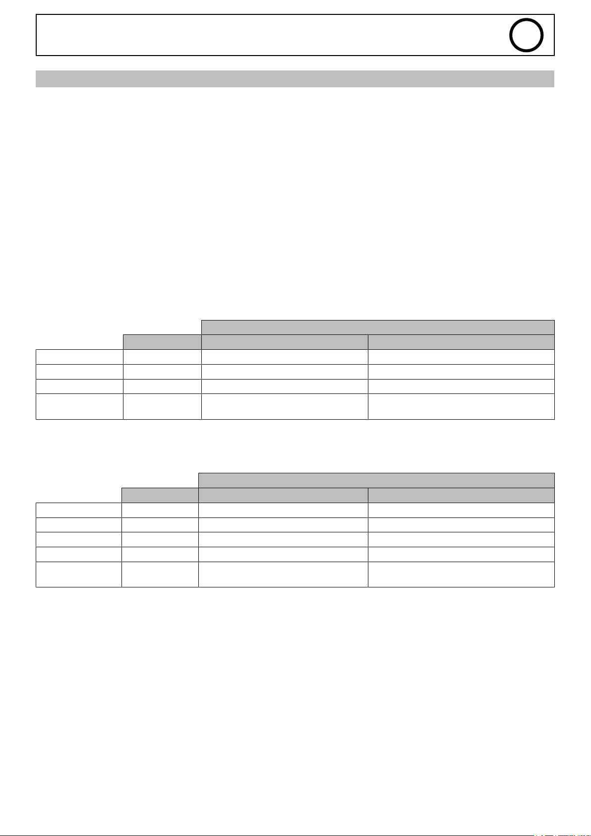
1. Entrées/Sorties digitales pour TITAN / TITANIUM
a) Entrées digitales
Le SAM-1A possède 4 entrées digitales TOR détaillées ci-dessous :
État
Connecteur-Pin 0 1
MMI_LOCK X20-18 Mode multimètre Courant-Tension Accès aux réglages du générateur
Start_Process X20-19 Arrêter la soudure Lancer le cycle de soudure
Start_Gaz X20-20 Electrovanne GAZ fermée Electrovanne GAZ ouverte
Wire_Feed
(Only in MIG)
b) Sorties Digitales
Ainsi que les 4 sorties digitales TOR suivantes :
Error X20-6 Pas d’erreur Erreur détectée
Authorised_Start X20-7 Soudure interdite Autorisé à souder
Arc_Detect X20-14 Arc non détecté Détection d’un arc
Welding_Process X20-8 Pas de soudure en cours Soudure en cours
Main_Current X20-13
X20-16 Fil arrêté Dévider le l
État
Connecteur-Pin 0 1
En dehors de la phase principale de
soudure
Dans la phase principale de soudure
2. Entrées/Sorties analogiques pour TITAN / TITANIUM
a) Sorties analogiques
Le SAM-1A possède deux sorties analogiques remontant les informations de mesure de tension et courant suivant les
caractéristiques :
Mesure Tension (M_Weld_Voltage, X20-5) => varie de 0 V à 10 V, correspond à une plage de mesure de 0 V à 50 V
Mesure Courant (M_Weld_Current, X20-15) => varie de 0 V à 10 V, correspond à une plage de mesure de 0 A à 500 A
16
Page 17
SAM-1A
b) Fonctions des entrées analogiques
I. Mode JOB – Sans réglages
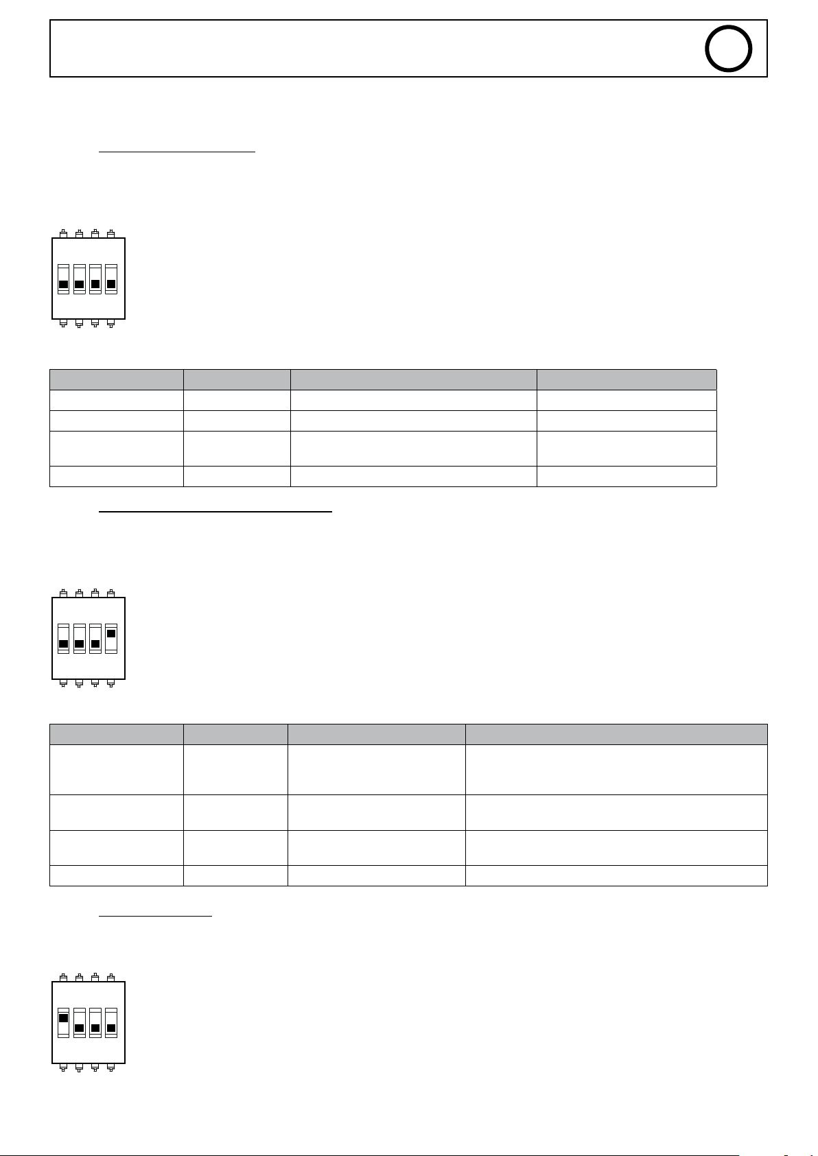
Tous les paramètres enregistrés dans le JOB sont utilisés (les valeurs sur les entrées 1, 2 et 3 ne sont donc pas prises en compte)
DIP2-SWITCH 1 = OFF (Mode : JOB)
DIP2-SWITCH 4 = OFF (JOB LOCK)
FR
1 2ON3 4
Tableau des valeurs réglables :
Entrée SAM-1A Connecteur-Pin Paramètre Valeur
INPUT_1 X20-1 - -
INPUT_2 X20-2 - -
INPUT_3 X20-4 Type de courant (Titanium seulement)
INPUT_4 X20-3 Numéro de JOB de 0 à 20
<5 V = DC
>5 V = AC
II. Mode JOB – Réglages depuis le SAM-1A
La valeur du paramètre Weld_Current du JOB est ignorée (la valeur est prise sur l’entrée du SAM-1A)
DIP2-SWITCH 1 = OFF (Mode : JOB)
DIP2-SWITCH 4 = ON (JOB UNLOCK)
1 2ON3 4
Tableau des valeurs réglables :
Entrée SAM-1A Connecteur-Pin Paramètre Valeur
INPUT_1 X20-1 ARC_LEN
10 V = +6
INPUT_2 X20-2 WELD_CURRENT
INPUT_3 X20-4
INPUT_4 X20-3 Numéro de JOB de 0 à 20
Type de courant
(Titanium seulement)
0 V = valeur mini du générateur
10 V = valeur max du générateur
<5 V = DC
>5 V = AC
0 V = -6
5 V = 0
III. Mode TRACKING
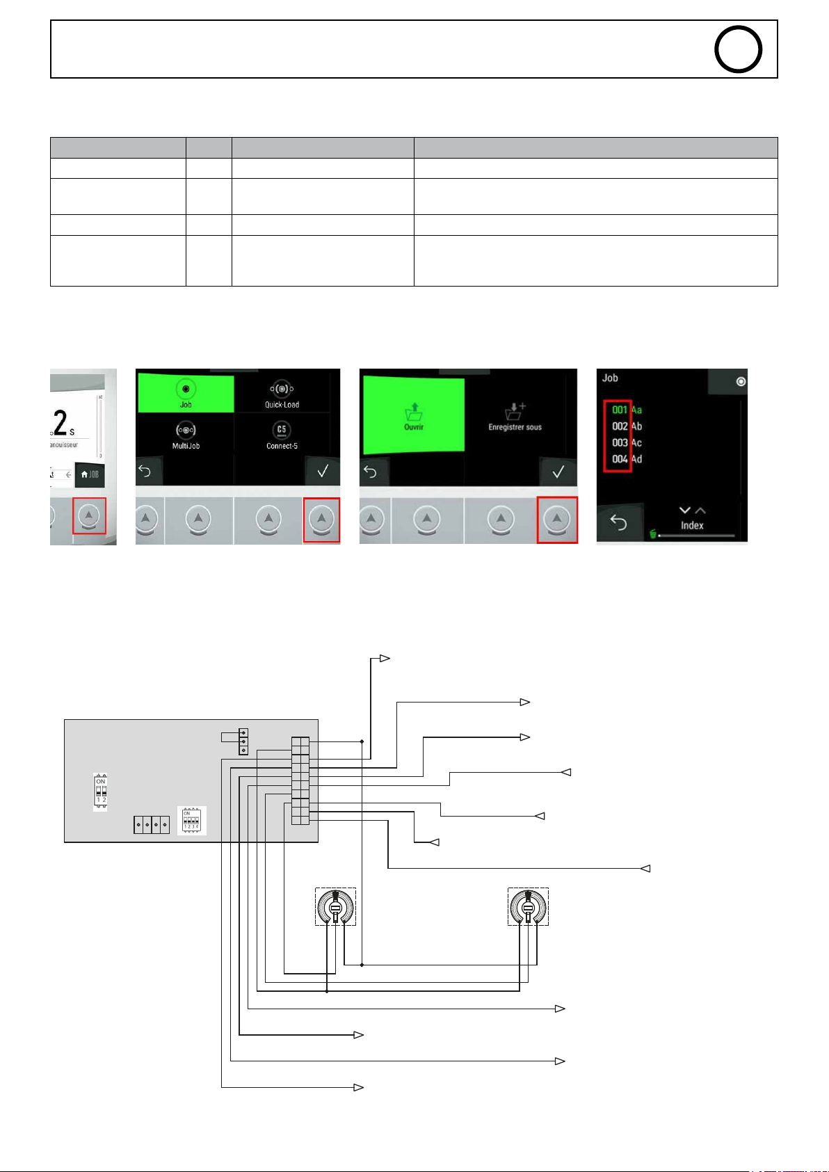
DIP2-SWITCH 1 = ON (Mode : TRACKING)
1 2ON3 4
17
Page 18
SAM-1A
Tableau des valeurs réglables :
Entrée SAM-1A Borne Paramètre Valeur
INPUT_1 X20-1 - -
INPUT_2 X20-2 WELD_CURRENT
INPUT_3 X20-4 Type de courant DC
INPUT_4 X20-3 Arc_Initiation
3. Où trouver le numéro du JOB ?
Sur la MMI du produit, suivre les étapes suivantes :
1 2 3 4
0 V = valeur mini du générateur
10 V = valeur max du générateur
< 1 V = HF
1 V à 2 V = Lift
2 V à 3 V = Touch_HF
FR
4. Exemple de schéma
TIG - MODE JOB - SANS RÉGLAGES - SAFETY DÉSACTIVÉE - ALIM 24V INTERNE
CN11T02
CON10T02
En dehors de la phase principale de soudure
13-MAIN_ CURRENT
CN11T01
3-IN PUT_4
4-IN PUT_3
10K
Réglage numéro de JOB
pas de JOB
0V =
0.5V = JOB 1
10V = JOB 20
0 =
Dans la phase principale de soudure
1 =
14-ARC_DETECT (0=PAS D ARC / 1=ARD DETECTE)
15-M_WELD_CURRENT
18-MMI_LOCK
19-START_PROCESS
0 = STOP
1 = START
10K
TITANIUM UNIQUEMENT
Réglage type de courant
<5V = DC
>5V = AC
0V = 0A
10V = 500A
16-WIRE_F EED (0=STOP / 1=START)
0 =
LOCK (mode multimètre)
UNLOCK (réglages générateur)
1 =
20-START_GAS
0 =
PAS D’ARC
ARC DÉTECTÉ
1 =
0 =
DÉVIDAGE OFF
DÉVIDAGE ON
1 =
0 =
1 =
GAZ OFF
GAZ ON
18
6-ERROR (0=OK / 1=ERREUR)
8-WELDING _PROCESS
0 =
1 =
0 =
OK
ERREUR
1 =
PAS DE SOUDURE
SOUDURE EN COURS
5-M_WELD_VOLTAGE
7-AUTHO RISED_ START
0V = 0V
10V = 50V
SOUDURE INTERDITE
0 =
SOUDURE AUTORISÉE
1 =
Page 19
SAM-1A
FR
ANNEXE 3 - RÉGLAGES DU SAM-1A EXAGON FLEX
1. Entrées/Sorties du SAM-1A .......................................................................................................................................... 19
a) Entrées digitales .................................................................................................................................................................19
b) Sorties digitales .................................................................................................................................................................. 19
2. Entrées/sorties analogiques ........................................................................................................................................19
a) Sorties analogiques ............................................................................................................................................................19
b) Fonctions des entrées analogiques ......................................................................................................................................19
I. Mode CV– Réglages depuis le Générateur .....................................................................................................................20
II. Mode CV – Réglages depuis le SAM-1A ......................................................................................................................... 20
3. Exemples de schéma .......................................................................................................................................................21
1. Détail des Entrées/Sorties du SAM-1A
a) Entrées digitales
Le SAM-1A possède 2 entrées digitales TOR (Tout ou Rien) détaillées ci-dessous :
Etat
0 1
MMI_LOCK X20-18 Mode multimètre Courant-Tension Accès aux réglages du
générateur
RUN X20-19 Interdire la soudure Autoriser la soudure
b) Sorties digitales
Ainsi que les 4 sorties digitales TOR (Tout ou Rien) suivantes :
Etat
0 1
Error X20-6 Pas d’erreur Erreur détectée
Authorised_Start X20-7 Soudure interdite Autorisé à souder
Arc_Detect X20-14 Arc non détecté Détection d’un arc
2. Détails des Entrées/Sorties analogiques
a) Sorties analogiques :
Le SAM-1A possède deux sorties analogiques remontant les informations de mesures de tension et courant suivant les caractéristiques suivantes :
Mesure Tension (M_Weld_Voltage, X20-5) => varie de 0V à 10V, correspond à une plage de mesure de 0V à 50V
Mesure Courant (M_Weld_Current, X20-15) => varie de 0V à 10V, correspond à une plage de mesure de 0A à 500A
b) Fonctions des entrées analogiques :
I. Mode CV– Réglages depuis le Générateur
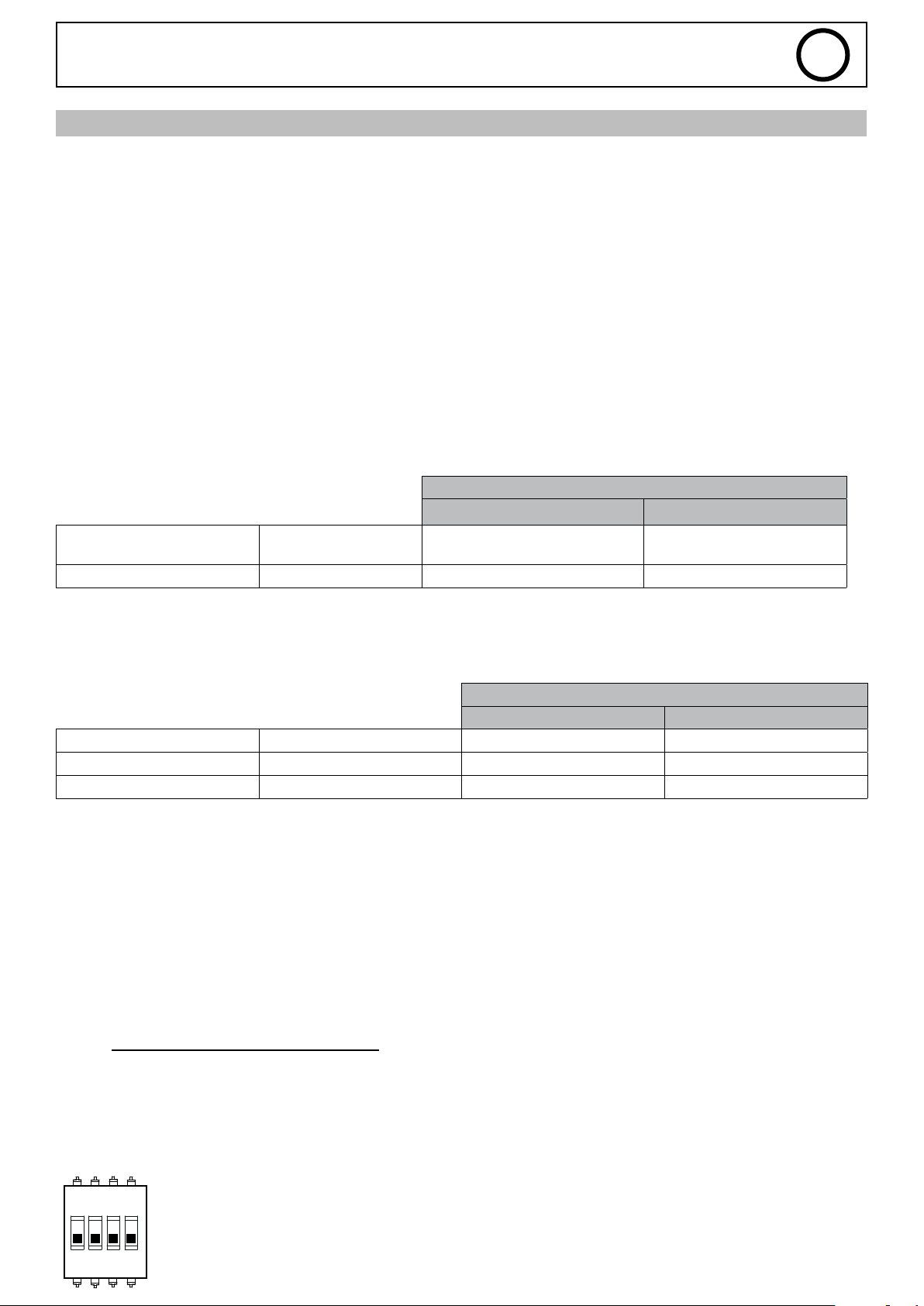
Les valeurs des paramètres I_Start,et Self du SAM-1A sont ignorées
DIP2-SWITCH 1=OFF (si ON : la soudure démarre directement)
DIP2-SWITCH 2=OFF
DIP2-SWITCH 4=OFF (les valeurs I_Start et Self sont celles du générateur)
1 2ON3 4
19
Page 20
SAM-1A
Tableau des valeurs réglables :
Entrée SAM-1A Paramètre Valeur
INPUT_1 X20-1
INPUT_2 X20-2
INPUT_3 X20-4
INPUT_4 X20-3 Weld Voltage
II. Mode CV– Réglages depuis le SAM-1A
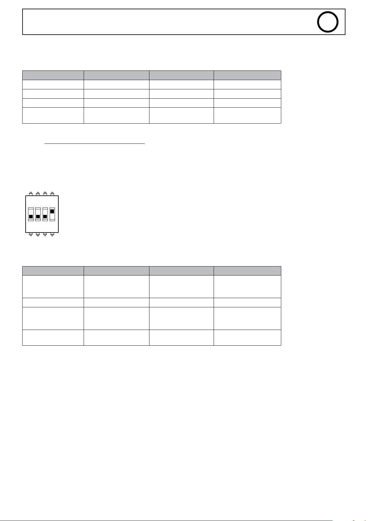
Les valeurs des paramètres I_Start,et Self du SAM-1A sont prises sur les entrées du SAM-1A
DIP2-SWITCH 1=OFF (si ON : la soudure démarre directement)
DIP2-SWITCH 2=OFF
DIP2-SWITCH 4=ON (les valeurs I_Start et Self sont celles du SAM-1A)
0V = 0V
10V = 50V
FR
1 2ON3 4
Tableau des valeurs réglables :
Entrée SAM1A Paramètre Valeur
INPUT_1 X20-1 I_Start
INPUT_2 X20-2
INPUT_3 X20-4 Self
INPUT_4 X20-3 Weld Voltage
0V = 0A
5V = 200A
10V = 400A
0V = -9
5V = 0
10V = +9
0V = 0V
10V = 50V
20
Page 21
SAM-1A
3. Exemples de schéma
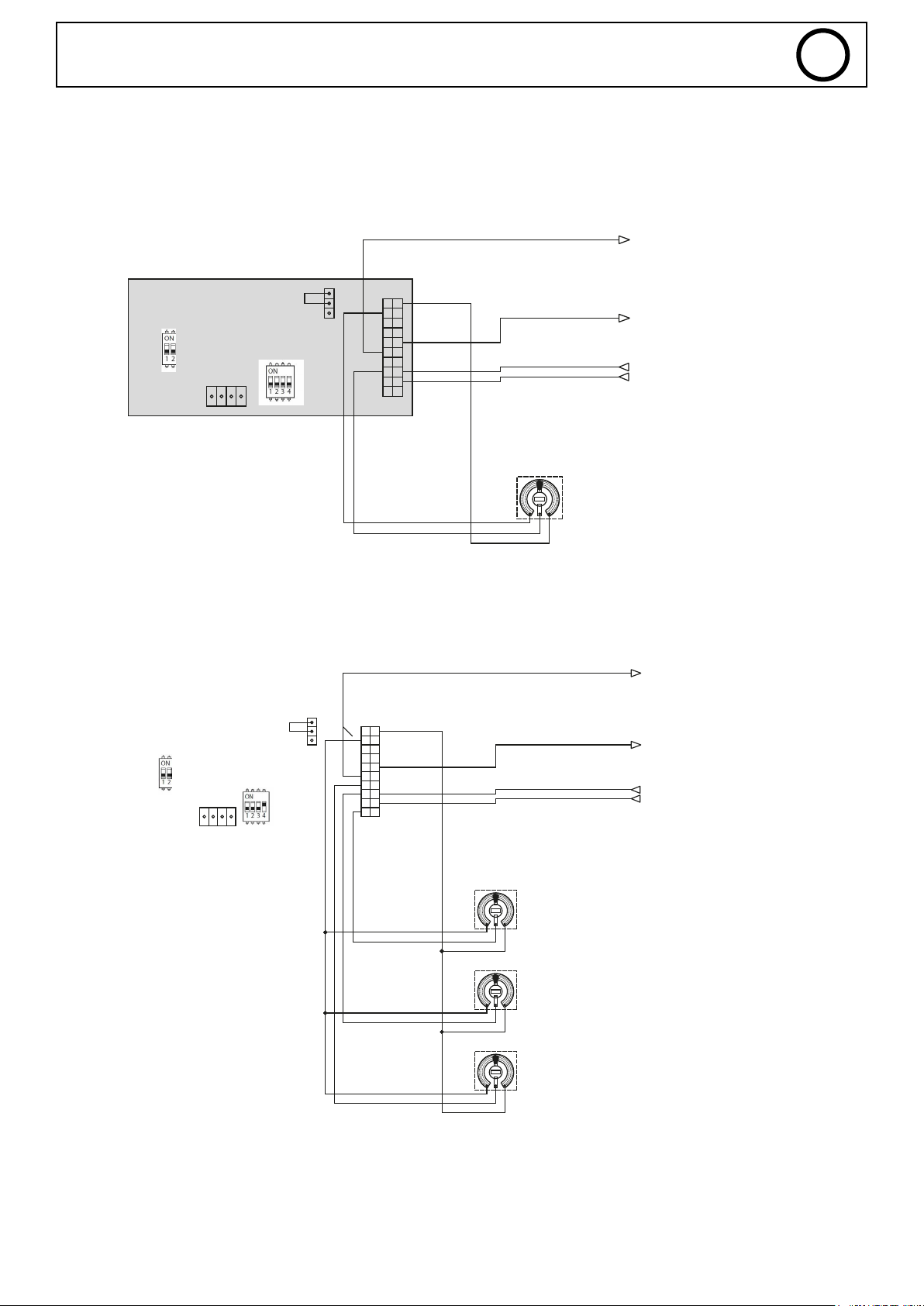
Conguration 1 : SAM-1A + EXAGON / MODE CV + RÉGLAGES GÉNÉRATEUR
EXAGON - MODE CV - REGLAGE GENERATEUR - SAFETY DESACTIVEE - ALIM 24V INTERNE
5-M_WELD_VOLTAGE
FR
Mesure tension
0V = 0V
10V = 50V
CN11T02
CON10T02
CN11T01
Conguration 2 : SAM-1A + EXAGON / MODE CV + RÉGLAGES SAM-1A
EXAGON - MODE CV - REGLAGE SAM-1A - SAFETY DESACTIVEE - ALIM 24V INTERNE
CN11T02
CN11T01
10K
15-M_WELD_CURRENT
18-MMI_LOCK
19-RUN
Réglage tension
0V = 0V
10V = 50V
5-M_WELD_VOLTAGE
15-M_WELD_CURRENT
Mesure courant
0V = 0A
10V = 500A
Mesure tension
0V = 0V
10V = 50V
Mesure courant
0V = 0A
10V = 500A
CON10T02
10K
10K
10K
Réglage I_Start
0V = 0A
5V = 200A
10V = 400A
Réglage Self
0V = -9
5V = 0
10V = +9
Réglage tension
0V = 0V
10V = 50V
18-MMI_LOCK
19-RUN
21
Page 22
SAM-1A
1. GENERAL INFORMATION
REVIEW
Review Date Modication
1.0 01/04/2022 Design
2.0 27/02/2023 Modication
3.0 05/09/2023 Modication
3.1 27/11/2023 Modication
3.2 25/06/2024 Modication
2. WARNINGS - SAFETY REGULATIONS
GENERAL ADVICE
This user’s manual contains information on the operation of the device and the precautions to be taken for
the safety of the user.
Please read it carefully before using the machine for the rst time and keep it for future reference.
These instructions must be read and understood before any operation.
Any modication or maintenance not specied in the manual must not be undertaken.
The manufacturer shall not be liable for any damage to persons or property arising from use not in
accordance with the instructions in this manual.
If you have any problems or uncertainties, please consult a qualied person to handle the appliance correctly.
This device may only be used for ticket printing and/or data transmission within the limits indicated on the
device and in the manual. The safety instructions must be observed. In case of improper or dangerous use,
the manufacturer cannot be held responsible.
EN
The device is intended for indoor use. It should not be exposed to rain.
Regulation :
The device complies with the European directives. The declaration of conformity is available on our website
(see cover page).
Material conforms to UK requirements. The UK Declaration of Conformity is available on our website (see
cover page).
This material is subject to separate collection in accordance with the European Directive 2012/19/EU. Do not
dispose of in domestic waste!
A recyclable product that is subject to sorting instructions.
ELECTRICAL SAFETY
When working on the product, be sure to secure the area by not allowing anyone who is not familiar with the safety instructions in
this user manual to enter the area. This device should preferably be installed by a professional according to the installation rules in
force in the particular country. If this is not possible, it is recommended that you read these rules before proceeding.
ELECTROSTATIC DAMAGE WARNING
Static electricity can damage electronic equipment. Use an earthed, antistatic wrist strap, ankle strap or equivalent
safety device to prevent electrostatic discharges (ESD) when installing this product.
Electrostatic damage can irreparably impair the power source and/or the entire product. To protect electronic components from
electrostatic damage, place this product on an antistatic surface, such as an antistatic discharge mat, antistatic bag or disposable
antistatic mat.
22
Page 23
SAM-1A
EN
3. PRODUCT OVERVIEW
INTRODUCTION
This document contains information on how to set up and connect the SAM-1A gateway in a PLC or automated network.
The Smart Automation Module (SAM-1A) is a communication tool between compatible GYS welding power sources and programmable
logic controllers (PLCs).
A SAM-1A connection converts GYS devices’ internal communication language into digital or analogue input/output signals.
The settings can be changed by using pre-loaded JOBs saved in the power source.
The power source/SAM-1A module assembly can be reassigned to a new system without requiring any modications to the system
(integrating it into a new machine, replacing a PLC or automating a process, etc.).
INTRODUCTION
The SAM-1A (PN. 071940) enables additional applications on compatible power sources.
The module allows access to parameters of the welding generator for control by the PLC or robot.
The following products are compatible:
Welding process Name Part Number
NEOPULSE 320 C 062474
NEOPULSE 400 CW 062061
MIG/MAG
TIG
PULSEMIG 400 CW 062658
NEOPULSE 400 G 014497
NEOPULSE 500 G 014503
EXAGON 400 FLEX CV 069718
KRYPTON 231 DC FV 075245
KRYPTON 321 DC 068094
TITAN 400 DC 013520
KRYPTON 401 DC 080904
TITANIUM 230 AC/DC FV 061996
TITANIUM 321 AC/DC 069879
TITANIUM 400 AC/DC 013568
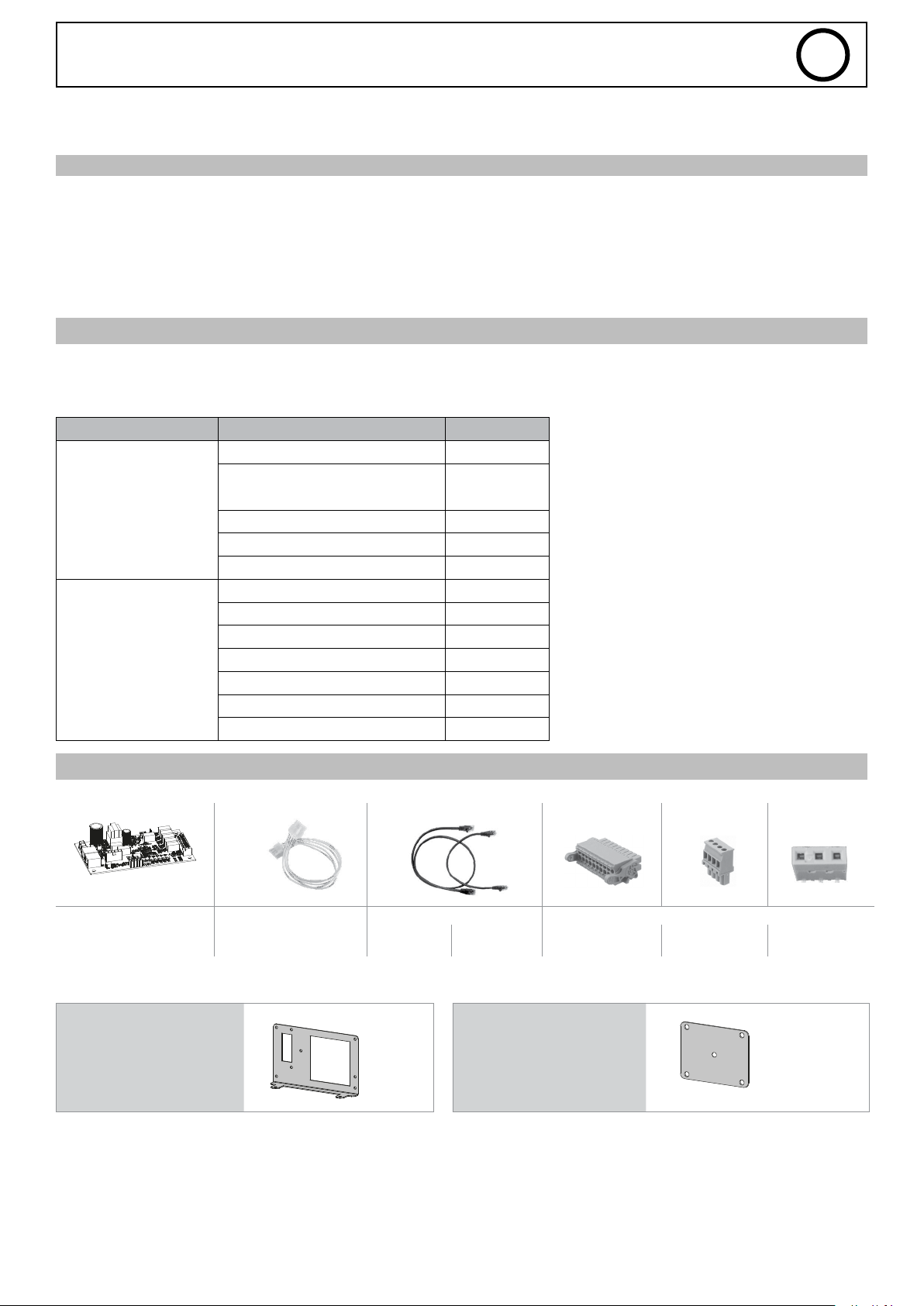
CONTENTS / SPARE PARTS
Electronic board
E0101C
Electronic board support brackets: Connector support plates:
NEOPULSE 320 C / 400 CW 98129
Cable bundle 300 mm RJ45 cables Connectors
F0035
300 mm
21574
750 mm
21575
NEOPULSE 320 C / 400 CW
EXAGON 400 FLEX
20 points
63851
4 points
53115
3 points strap
K0535GF
23
Page 24
SAM-1A
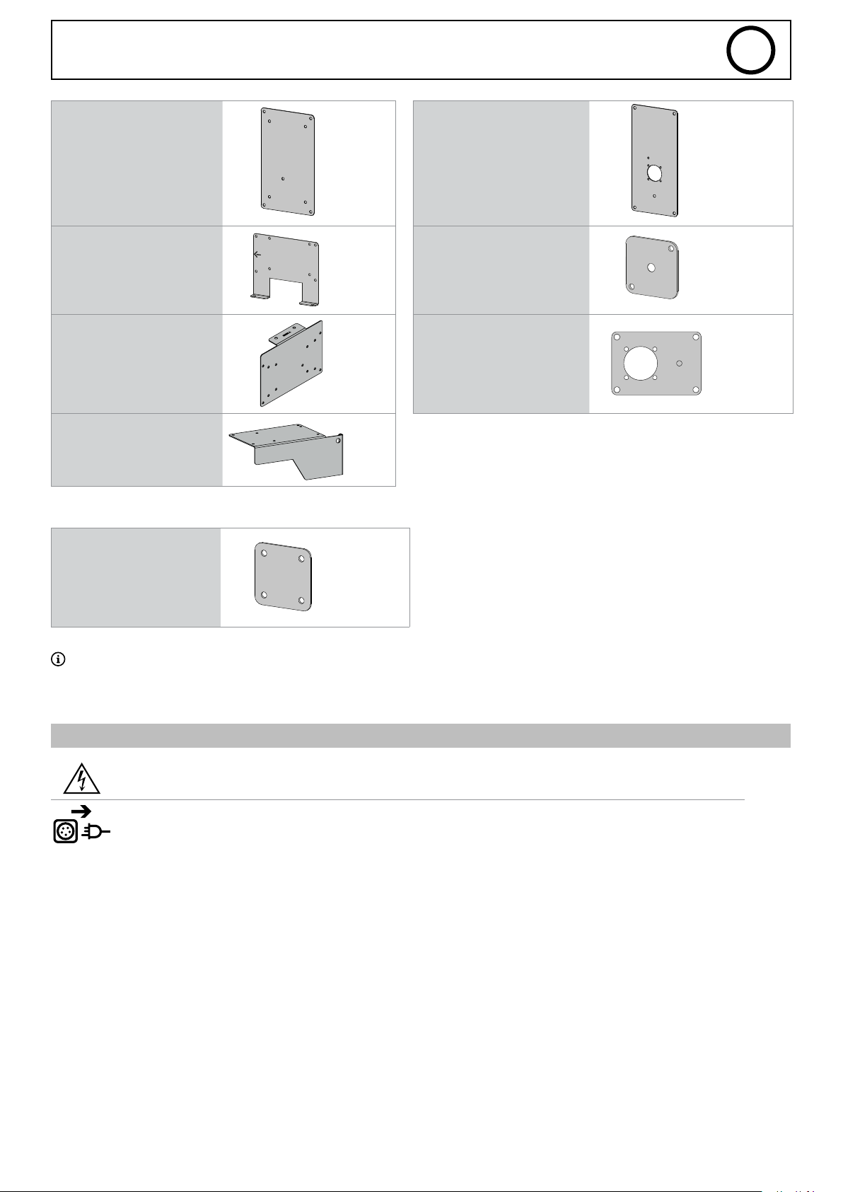
NEOPULSE 400 G / 500 G K0539Z NEOPULSE 400 G / 500 G K0536GF4
KRYPTON 231 DC FV
KRYPTON 321/401 DC
TITAN 400
TITANIUM 400 AC/DC
TITANIUM 321 AC/DC
EXAGON 400 FLEX
TITANIUM 230 AC/DC K0402
98116
K0538
TITAN 400
TITANIUM 400
KRYPTON 231 DC FV
KRYPTON 321/401 DC
TITANIUM 230 AC/DC
TITANIUM 321 AC/DC
EN
K0537GF
K1146GF
Connector cover plate:
KRYPTON 231 DC FV
KRYPTON 321/401 DC
TITANIUM 230 AC/DC
TITANIUM 321 AC/DC
NEOPULSE 400 G / 500 G
Some congurations do not require all the kit’s items.
4. SETTING UP THE DEVICE
INSTALLATION
WARNING
ELECTRIC SHOCKS CAN BE FATAL
Only experienced personnel authorised by the manufacturer may install the equipment. During installation,
ensure that the power source is disconnected from the mains.
Kit installation :
99089GF
EXAGON / NEOPULSE /
TITAN / TITANIUM 400
Access to internal areas beyond those outlined in this manual is prohibited and voids the warranty as well as all other forms of support. Indeed, these interventions can be damaging to the power source’s internal electronic parts and/or components.
TITANIUM 230
AC/DC
TITANIUM 321
AC/DC
KRYPTON 401
DC
24
Page 25
SAM-1A
EN
SWO FEATURE (SAFE WELDING OFF)
The «Safe Welding O» function mainly prevents the current or voltage source from starting. It acts directly on the power source
in a very short time.
This function is also used to safely stop the power source in the event of an emergency stop. This avoids a sudden power supply
interruption to the power source if a problem arises. It should be remembered that a break in the power supply downstream of a
loaded power source is dangerous and can damage the equipment.
I. Electrical safety
The «Safe Welding O» function does not oer electrical isolation; therefore, before any work is carried out on the power source, it
must be electrically isolated by switching o the power supply and locally isolating the power source (padlock procedure).
II. SWO activation and wiring
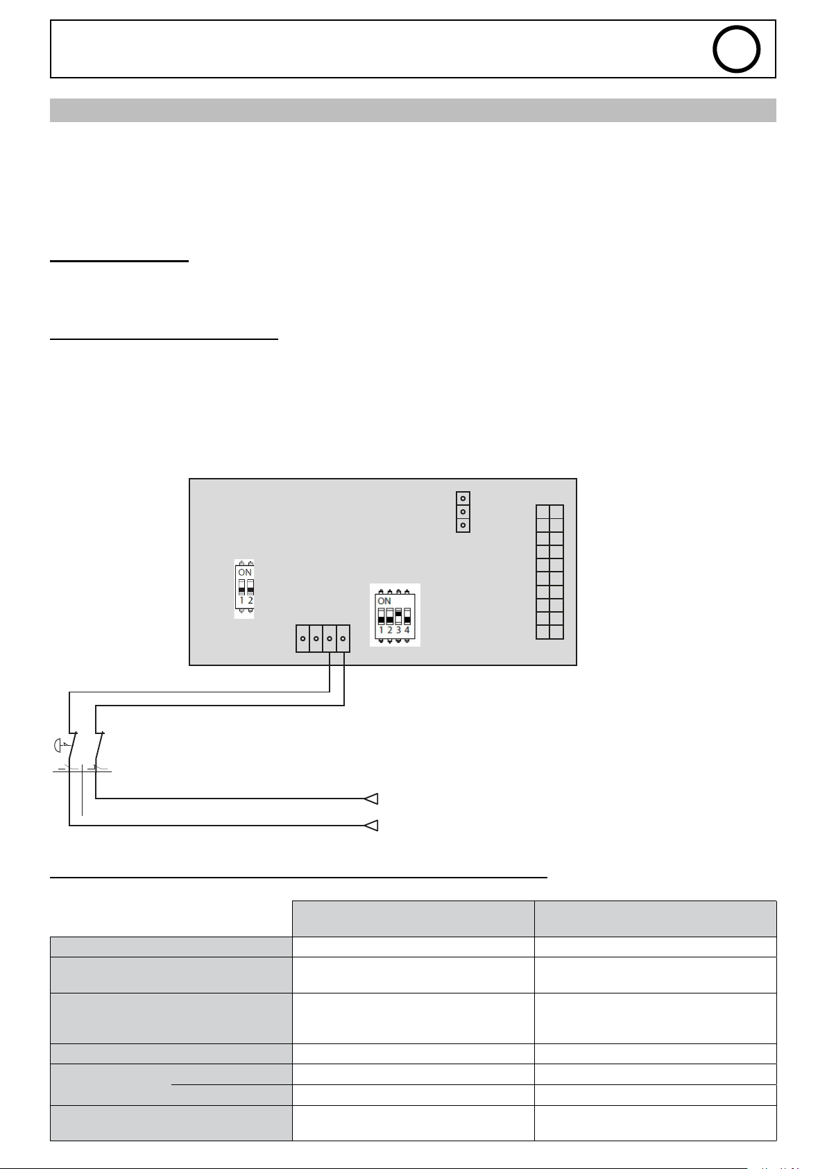
Two switches (DIP 1 and DIP 2), located on the SAM-1A board (see electronic board on page
30), are provided to set the security function and the various functions of the SAM-1A board.
To activate the security function, simply switch the 2 DIP 1 switches to ON and DIP 2 switch 3 to ON.
In this case, it is necessary to wire the security. A terminal block (X5) is available on the SAM-1A electronic board (see electronic
board on page 30).
Principle diagram:
CN11T02
CON10T02
A1 A2
CN11T01
EMERGENCY
STOP
1-D2
0V
Alimentation
Power supply
24Vdc
III. Electrical characteristics of terminal block X5 inputs/outputs
OUTPUT
(feedback)
Insulation type Dry contact Relay
Connection
Voltage range 20 - 30 VDC
Current rating at 24 VDC Max. 2 A 10 mA
Current rating
Test pulse train
< 1 ms at frequencies below 100 Hz
response time
max. time
3- S13 contact NO
4- S14 Vcc
15 VDC logic threshold
Maximum low voltage at 3 V
8 ms 4 ms
16 ms 8 ms
No response No response
INPUT
1- AU_A2 : Earth
2- AU_A2 : VCC
20 - 30 VDC
25
Page 26
SAM-1A
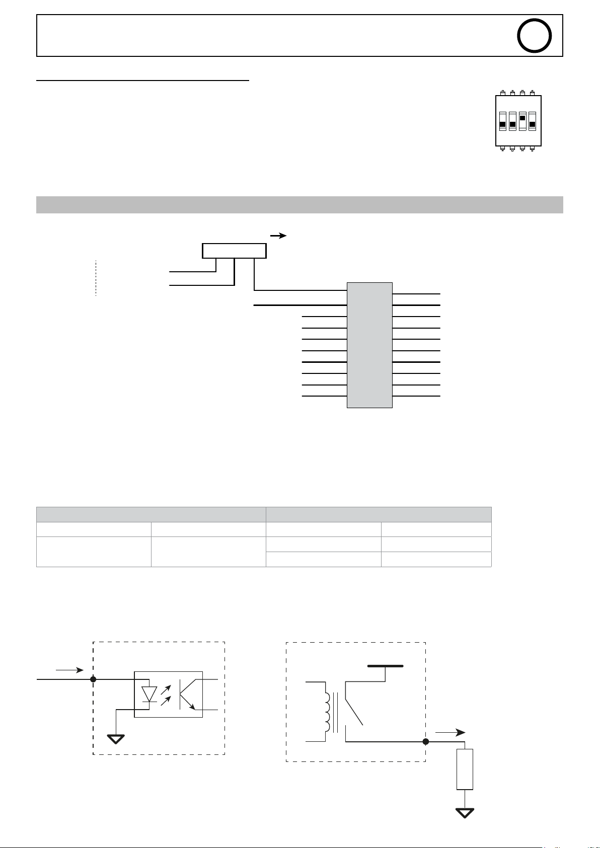
VI. Activating the SWO function (Soft)
A switch (DIP 2), located on the SAM-1A board (see page 30), provides the user with a way to set the various
SAM-1A board functions. In order to activate the safety feature, switch 3 must be set to ON.
5. INPUT/OUTPUT ASSIGNMENTS
CONNECTOR X20 TECHNICAL SPECIFICATIONS
EN
1 2ON3 4
POWER
24V
internal 24Vdc
common
Power supply
3
MASSE
WELDING_PROCESS MAIN_CURRENT
AUTHORISED_START
M_WELD_VOLTAGE
2
1
INPUT_3
INPUT_4
INPUT_2
INPUT_1
see information on page 26 and 30
EXTERNAL 24Vdc
X20
10
9
8
7
ERROR
6
5
4
3
2
1 20
11
12
13
14
15
16
17
18
19
ALIM_LIMIT_+10V
RESERVED_2
ARC_DETECT
M_WELD_CURRENT
WIRE_FEED
RESERVED_1
MMI_LOCK
START_PROCESS
START_GAZ
• Power supply
The inputs/outputs (24 V) can be supplied either internally by the SAM-1A or by an external, 24 V power supply.
The SAM-1A is set up for an internal power supply as standard.
To use an external power supply, simply switch the jumper on the three-pin power connector (see electronic board on page 30)
and apply 24 V to the X20 connector (pin 10).
A 3 points strap is supplied with the product (bag of wires and connectors) enabling the internal power supply to be used and
directed to the outside of the product.
Internal power supply External 24 V power supply
Rated voltage Rated current Maximum voltage Maximum current
24 V 100 mA
24 V 2 A
10 V 20 mA
• Digital inputs/outputs
Digital inputs Digital outputs
Electronic card SAM-1A
10 mA
26
Electronic card SAM-1A
+24 V
2 A
L
O
A
D
Page 27
SAM-1A
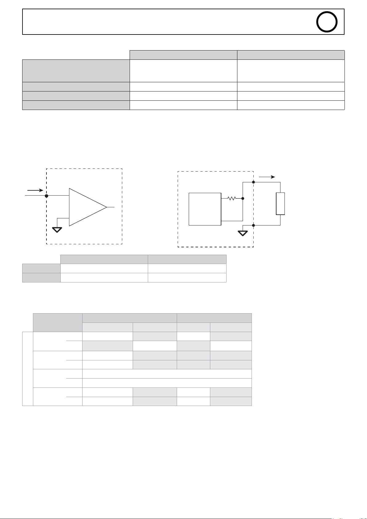
SAM digital input/output overview and technical data:
Output Input
DRY contact 24 VDC
Insulation type
ON Voltage Vmin/Vmax +20 - +30 V 15 - 28 VDC
OFF Voltage Vmin/Vmax 0 - 5 VDC
Rated current at +24 V Max. 2 A 5 mA
1 - 24 VDC
2-5 - DO1 – DO4 (NO)
• Analogue inputs/outputs
Analogue inputs Analogue outputs
500 VDC isolation photocoupler
6-9 - DI1 – DI4 (NO)
10 - Earth (0 V)
EN
Electronic card SAM-1A
10 mA
+
1
-
Output Input
Voltage 0 - 10 V 0 - 10 V
Current 100 µA 1 mA
• DIP 2 settings
Description
SWITCH-1
SWITCH-2
SWITCH-3
DIP Switch
SWITCH-4
JOB Manual JOB CC Tracking
OFF JOB Mode JOB Mode
ON Manual Mode Tracking Mode
ON Weld_Current
OFF Wire_Speed
OFF Safety disabled
ON Safety activated
OFF Job Lock Job Lock
ON Job Unlock Job Unlock
MIG TIG
Electronic card SAM-1A
DAC
0-10 V
100 μA
L
O
A
D
27
Page 28
Welding Process
DELTA
SAM
CPU
CPU
CPU
CPU
SAM
SAM
Emitter
Process Control (1)
FOR TIG AC/DC
Authorised_Start
Welding Trigger_CMD
Welding Process
Function
Setting Values
0,1s
Authorised Start
Function
Start Gas
Welding Current
Welding Process
SAM
CPU
CPU
Emitter
SAM
100A
200A
Average cycle Current
Function
Start Process
Welding Process
GAS ON
Arc detect
Main Current
SAM
CPU
Emitter
SAM
SAM
SAM
Pregas Start Upslope Welding Downslope Stop Post-gas
73.1
90
71
2.1
3.0
73.1
Process Control (1)
FOR TIG AC/DC
JOB number
Authorised_Start
Welding Trigger_CMD
Welding Process
DELTA
CPU
CPU
CPU
CPU
SAM
SAM
Emitter
Function
0,1s
0,1s
CPU
CPU
CPU
CPU
SAM
SAM
Emitter
Process Control (1)
FOR TIG AC/DC
Authorised_Start
Welding Trigger_CMD
Welding Process
Function
Setting Values
0,1s
71
72
2.1
3.0
73.1
90
71
2.1
3.0
73.1
PARAM
Process Control (1)
FOR TIG AC/DC
JOB number
Authorised_Start
Welding Trigger_CMD
Welding Process
DELTA
CPU
CPU
CPU
CPU
SAM
SAM
Emitter
Function
0,1s
0,1s
CPU
CPU
CPU
CPU
SAM
SAM
Emitter
Process Control (1)
FOR TIG AC/DC
Authorised_Start
Welding Trigger_CMD
Welding Process
Function
Setting Values
0,1s
Authorised Start
Function
Start Gas
Welding Current
Welding Process
SAM
CPU
CPU
Emitter
SAM
100A
200A
71
72
2.1
3.0
73.1
90
71
2.1
3.0
73.1
PARAM
SAM-1A
EN
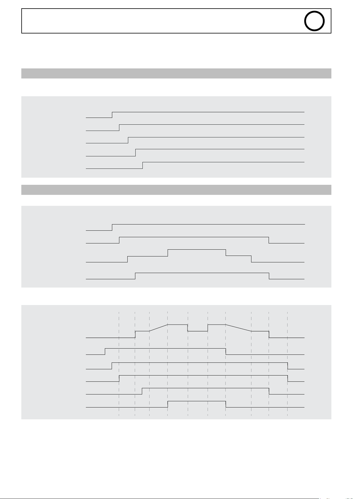
6. WELDING PROCESSES
This chapter contains diagrams of dierent welding processes.
A) SCHEMATIC DIAGRAM OF THE WELDING CYCLE
Function
FOR TIG AC/DC
JOB number
Authorised Start
Start Process
Welding Process
B) SCHEMATIC DIAGRAM OF A WELDING CYCLE IN TRACKING MODE
Function
Authorised Start
Start Gas
Welding Current
0,1s
100A
Job Mode init
Tracking Mode TIG
200A
Emitter
CPU
CPU
SAM
CPU
SAM
Emitter
SAM
CPU
CPU
Welding Process
Function
Average cycle Current
Start Process
Welding Process
GAS ON
Arc detect
Main Current
Welding cycle
Pregas Start Upslope Welding Downslope Stop Post-gas
SAM
Emitter
CPU
SAM
SAM
SAM
SAM
28
Page 29
Start Process
Welding Process
GAS ON
Arc detect
Main Current
SAM
CPU
SAM
SAM
SAM
Function
FOR TIG AC/DC
JOB number
Authorised Start
Start Process
Welding Process
SAM
CPU
CPU
CPU
SAM
Emitter
0,1s
Function
Process Control (1)
TIG_Type (TIG AC/DC)
User Setting
Authorised_Start
Welding Simuler
Welding Trigger_CMD
Welding Process
0,1s
CPU
Emitter
CPU
CPU
CPU
CPU
SAM
SAM
Function
Recovery_Weld
Arc detect
Arc initiate
CPU
Emitter
SAM
Arc
C) SCHEMATIC DIAGRAM IN CASE OF AN ERROR
Function
Average cycle Current
Error state
Authorised Start
Gas ON
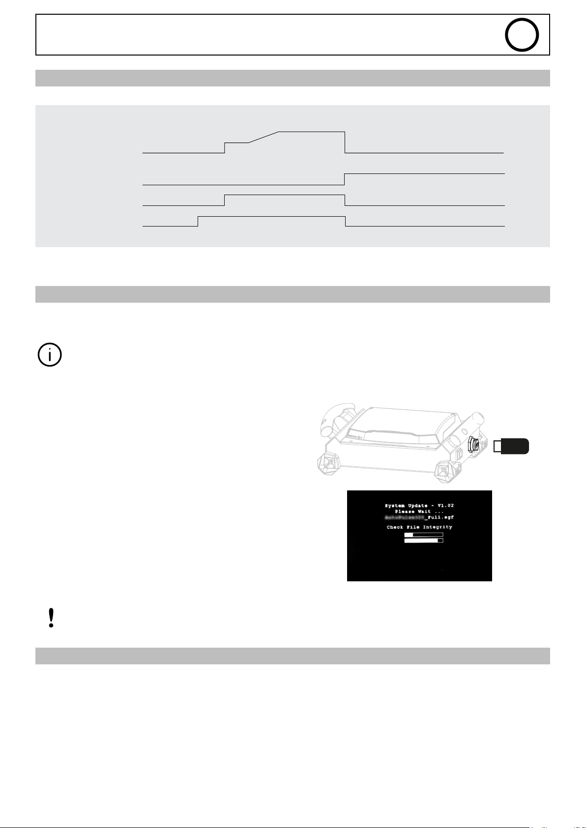
7. MAINTENANCE
UPDATES
Before using the product for the rst time, it is recommended to check whether a new software update is available on the GYS
after-sales service site (customer code required).
SAM-1A
Error
Welding Downslope Stop
Post-gas
EN
Emitter
SAM
SAM
SAM
SAM
A single update allows the user to update all connected products (power source, remote control, wire-feed reel and SAM,
etc).
1- Disconnect all devices from the network.
2- Connect a USB key containing the latest updates to the
specic USB port and start the device.
3- The screen comes on if a new software version is detected. Wait until the step is complete and restart the product
after having disconnected the USB key.
Before upgrading, check the changes made by the new rmware update. In the event of a major
software update, changes may be required to the PLC’s software programming.
DEFECTS LIST
Please refer to the after-sales section of the website www.gys.fr.
29
Page 30
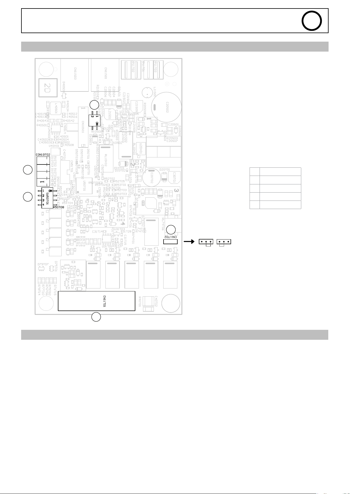
ELECTRONIC BOARD
SAM-1A
5
EN
4
3
1
WARRANTY CONDITIONS FRANCE
1 X20
2 Power supply
3 DIP 2
4 X5
5 DIP 1
2
Internal
External
The warranty covers any defects or manufacturing faults for two years from the date of purchase (parts and labour).
The warranty does not cover:
• Any damage caused by transporting the device.
• The normal wear and tear of the parts (e.g. : cables and clamps, etc.).
• Incidents due to misuse (incorrect wire feeding, dropping or dismantling the machine, etc.).
• Environmental failures (pollution, rust or dust, etc).
In the event of a breakdown, return the appliance to your distributor, enclosing:
- a dated proof of purchase (receipt or invoice, etc.)
- a note explaining the breakdown
30
Page 31
SAM-1A
EN
APPENDIX 1 - SAM-1A SETTINGS USING THE NEOPULSE/PULSEMIG
1. NEOPULSE/PULSEMIG digital inputs/outputs ..................................................................................................... 31
a) Digital inputs .....................................................................................................................................................................31
b) Digital outputs ...................................................................................................................................................................31
2. NEOPULSE/PULSEMIG analogue inputs/outputs ............................................................................................... 31
a) Analogue outputs ............................................................................................................................................................... 31
b) Analogue input functions ....................................................................................................................................................32
I. JOB mode - Without settings ........................................................................................................................................ 32
II. JOB mode - Current settings ........................................................................................................................................ 32
III. JOB mode - Wire-speed settings ................................................................................................................................... 32
IV. Manual Mode .............................................................................................................................................................. 33
3. Where to nd the JOB number .................................................................................................................................... 33
4. Where to nd the synergy values .............................................................................................................................. 34
5. How to change the management mode to nd the min./max. setting values ......................................34
6. Example of diagram .........................................................................................................................................................34
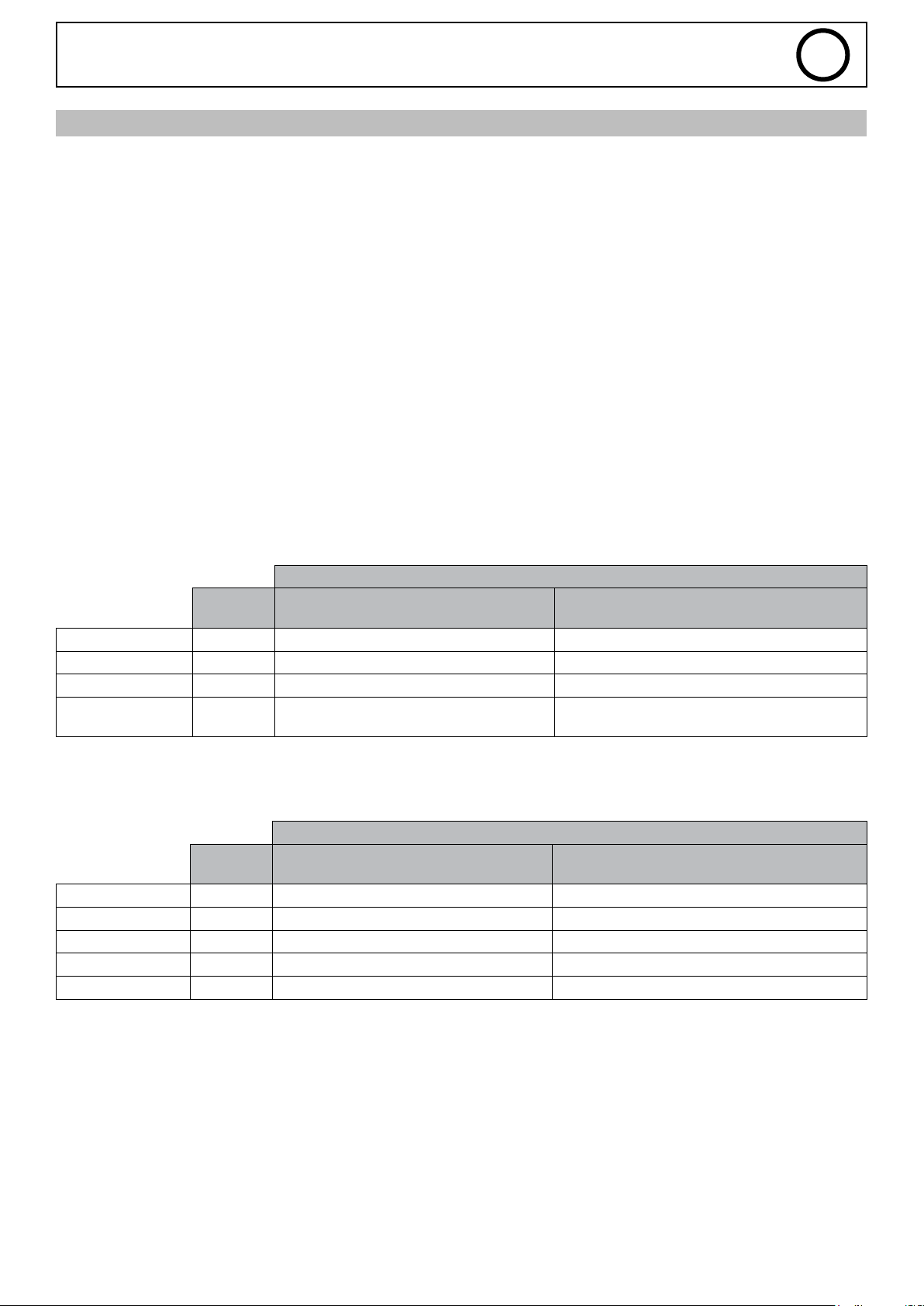
1. Digital inputs/outputs for NEOPULSE/PULSEMIG machines
a) Digital inputs
The SAM-1A has four digital inputs as detailed below:
Status
Pin
Connector
MMI_LOCK X20-18 Current-Voltage multimeter mode Accessing the power source settings
Start_Process X20-19 Stopping the welding process Starting the welding cycle
Start_Gaz X20-20 GAS solenoid valve closed GAS solenoid valve open
Wire_Feed
(only in MIG)
b) Digital outputs
As well as the following four digital outputs:
Error X20-6 No error Error detected
Authorised_Start X20-7 Welding prohibited Welding permitted
Arc_Detect X20-14 Arc not detected Arc detected
Welding_Process X20-8 No welding in progress Welding in progress
Main_Current X20-13 Outside the main welding phase In the main welding phase
X20-16 Wire stopped Unwinding the wire
Pin
Connector
0 1
Status
0 1
2. NEOPULSE/PULSEMIG analogue inputs/outputs
a) Analogue outputs
The SAM-1A has two analogue outputs providing voltage- and current-measurement information as follows:
Voltage measurement (M_Weld_Voltage, X20-5): varies from 0 - 10 V and covers a measurement range of 0 - 50 V.
Current measurement (M_Weld_Current, X20-15): varies from 0 - 10 V and covers a measurement range of 0 - 500 A.
31
Page 32
SAM-1A
b) Analogue input functions
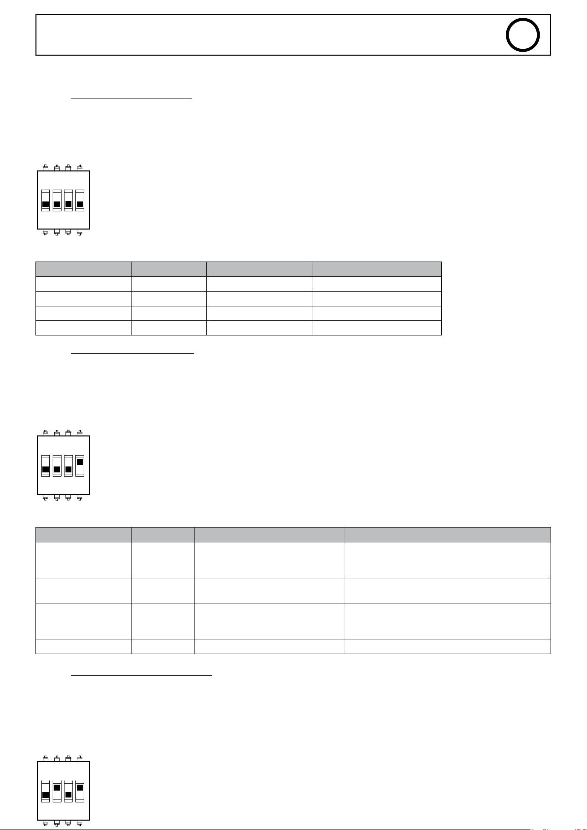
I. JOB mode - Without settings
All parameter settings stored in JOB mode are used (the values of inputs 1, 2 and 3 are, therefore, not taken into account).
DIP2-SWITCH 1 = OFF (Mode: JOB)
DIP2-SWITCH 2 = OFF
DIP2-SWITCH 4= OFF (JOB LOCK)
1 2ON3 4
Table of adjustable values:
SAM-1A input Pin Connector Setting Value
INPUT_1 X20-1 - -
INPUT_2 X20-2 - -
INPUT_3 X20-4 - -
INPUT_4 X20-3 JOB number between 1 - 20
EN
II. JOB mode - Current settings
The current parameter setting values, Arc_LEN, Self and Weld_Current in JOB mode are disregarded (the values are taken from the
SAM-1A inputs).
DIP2-SWITCH 1 = OFF (Mode: JOB)
DIP2-SWITCH 2 = OFF (Management: Current)
DIP2-SWITCH 4 = ON (JOB UNLOCK)
1 2ON3 4
Table of adjustable values:
SAM-1A input Pin Connector Setting Value
0 V = -6
INPUT_1 X20-1 ARC_LEN
INPUT_2 X20-2 WELD_CURRENT
INPUT_3 X20-4 SELF
INPUT_4 X20-3 JOB number between 0 - 20
0 V = minimum synergy value
10 V = maximum synergy value
5 V = 0
10 V = +6
0 V = -4
5 V = 0
10 V = +4
III. JOB mode - Wire-speed settings
The parameter setting values, Arc_LEN, Self and Wire_Weld_Speed in JOB mode are disregarded (the values are taken from the
SAM-1A inputs).
DIP2-SWITCH 1 = OFF (Mode: JOB)
DIP2-SWITCH 2 = ON (Management: Wire speed)
DIP2-SWITCH 4 = ON (JOB UNLOCK)
32
1 2ON3 4
Page 33
SAM-1A
Table of adjustable values:
SAM-1A input Pin Connector Setting Value
INPUT_1 X20-1 ARC_LEN
INPUT_2 X20-2 WIRE_WELD_SPEED
INPUT_3 X20-4 SELF
INPUT_4 X20-3 JOB number between 0 - 20
IV. MANUAL Mode
DIP2-SWITCH 1 = ON (Mode: MANUAL)
0 V = minimum synergy value
10 V = maximum synergy value
EN
0 V = -6
5 V = 0
10 V = +6
0 V = -4
5 V = 0
10 V = +4
1 2ON3 4
Table of adjustable values:
SAM-1A input Pin Connector Setting Value
INPUT_1 X20-1 WELD_VOLTAGE
INPUT_2 X20-2 WIRE_WELD_SPEED
INPUT_3 X20-4 CHOKE
INPUT_4 X20-3 - -
0 V = minimum synergy value
10 V = maximum synergy value
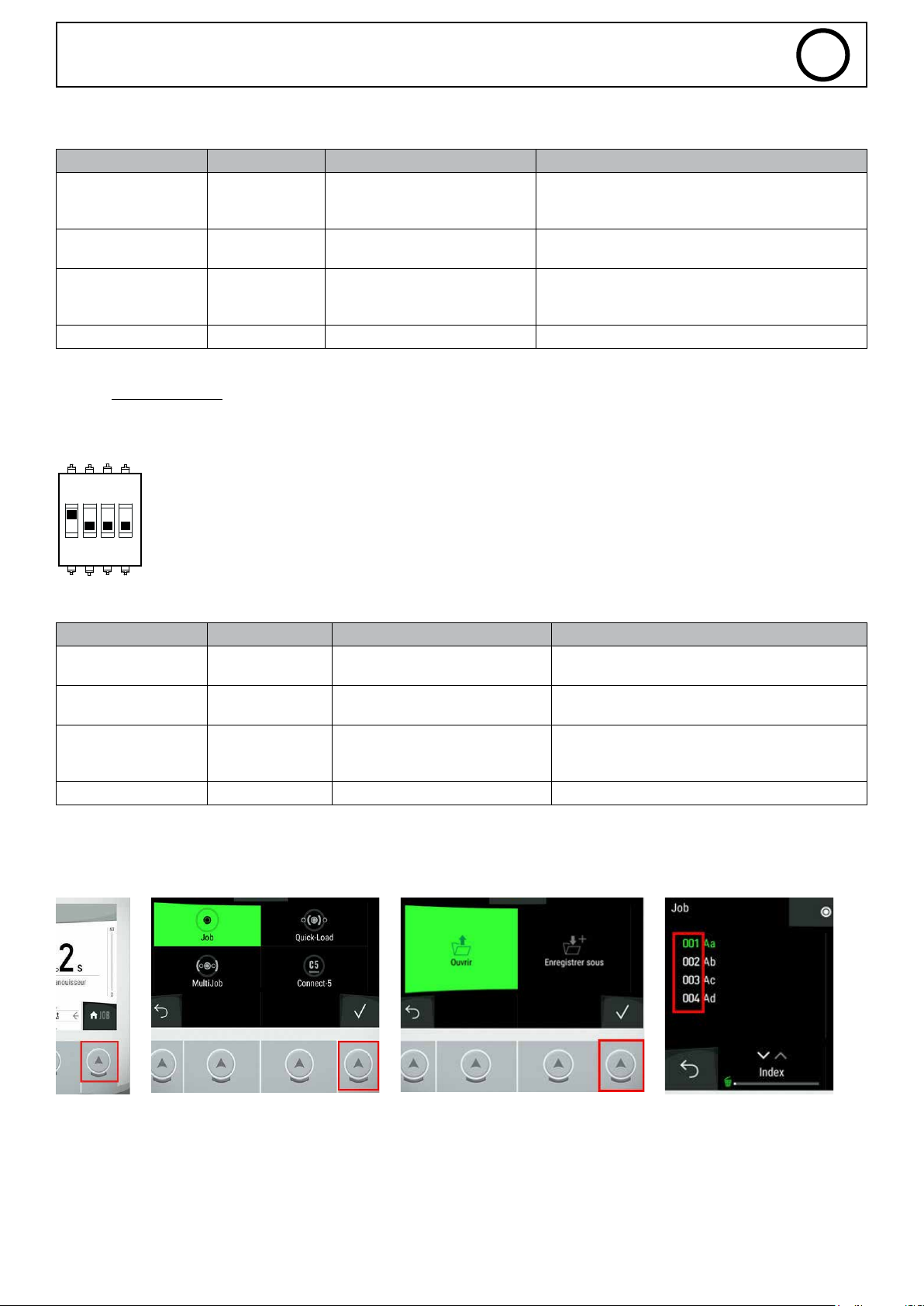
3. Where to nd the JOB number?
On the product’s man machine interface (MMI), complete the following steps:
1 2 3 4
0 V = 0 V
10 V = 50 V
0 V = -4
5 V = 0
10 V = +4
33
Page 34
SAM-1A
1 =
WELDING IN PROGRESS
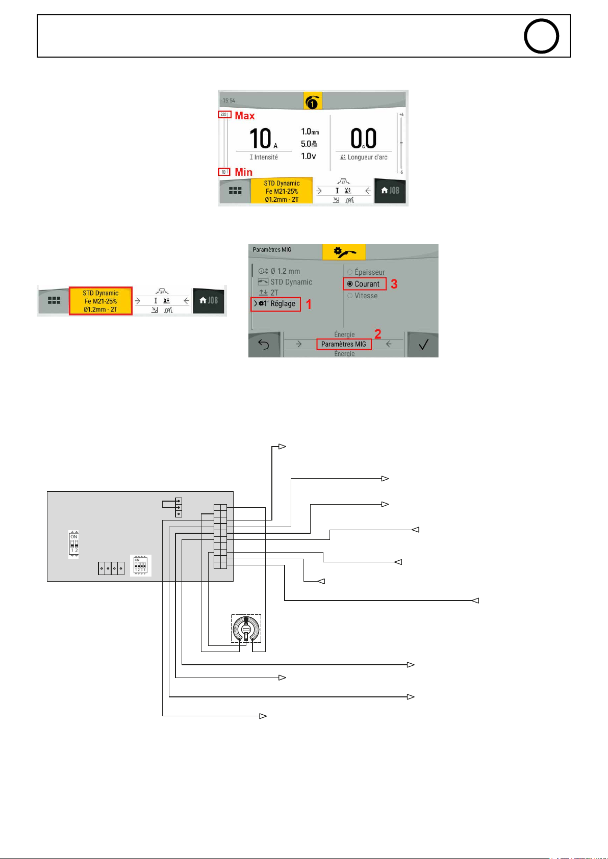
4. Where to nd the synergy values?
From the product’s MMI, the MIN. and
MAX. synergy values are indicated on the
left-hand cursor.
5. How to change the management mode to nd the min./max. values?
From the JOB menu on the product’s MMI
EN
6. Example of diagram
MIG - JOB MODE - NO SETTINGS - SAFETY DEACTIVATED - INTERNAL 24V POWER SUPPLY
CN11T02
CON10T02
CN11T01
3-IN PUT_4
10K
JOB number setting
0V =
0.5V = JOB 1
10V = JOB 20
8-WELDING _PROCESS
13-MAIN_ CURRENT
0 =
1 =
19-START_PROCESS
no JOB
6-ERROR (0=OK / 1=ERREUR)
0 =
NO WELDING
Outside the main welding stage
In the main welding stage
14-ARC_DETECT (0=PAS D ARC / 1=ARD DETECTE)
15-M_WELD_CURRENT
18-MMI_LOCK
0V = 0A
10V = 500A
16-WIRE_F EED (0=STOP / 1=START)
0 =
1 =
0 = STOP
1 = START
0 =
1 =
OK
ERROR
5-M_WELD_VOLTAGE
7-AUTHO RISED_ START
NO ARC
0 =
ARC DETECTED
1 =
0 =
FEED OFF
FEED ON
1 =
LOCK (multimeter mode)
UNLOCK (generator settings)
GAS OFF
20-START_GAS
0 =
1 =
GAS ON
0V = 0V
10V = 50V
WELDING PROHIBITED
0 =
AUTHORIZED WELDING
1 =
34
Page 35
SAM-1A
EN
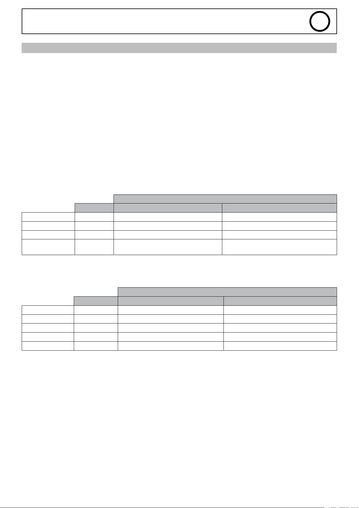
APPENDIX 2 - SAM-1A SETTINGS USING THE TITAN/TITANIUM
1. Digital inputs/outputs ....................................................................................................................................................35
a) Digital inputs .....................................................................................................................................................................35
b) Digital outputs ...................................................................................................................................................................35
2. Analogue input/outputs ................................................................................................................................................. 35
a) Analogue outputs ............................................................................................................................................................... 35
b) Analogue input functions ....................................................................................................................................................36
I. JOB mode - Without settings ........................................................................................................................................ 36
II. JOB mode - SAM-1A settings ....................................................................................................................................... 36
III. Tracking Mode.............................................................................................................................................................36
3. Where to nd the JOB number .................................................................................................................................... 37
4. Example of diagram .........................................................................................................................................................37
1. The TITAN/TITANIUM’S DIGITAL INPUTS/OUTPUTS
a) Digital inputs
The SAM-1A has four digital inputs as detailed below:
Status
Pin Connector 0 1
MMI_LOCK X20-18 Current-Voltage multimeter mode Accessing the power source settings
Start_Process X20-19 Stopping the welding process Starting the welding cycle
Start_Gaz X20-20 GAS solenoid valve closed GAS solenoid valve open
Wire_Feed
(only in MIG)
b) Digital outputs
As well as the following four digital outputs:
Error X20-6 No error Error detected
Authorised_Start X20-7 Welding prohibited Welding permitted
Arc_Detect X20-14 Arc not detected Arc detected
Welding_Process X20-8 No welding in progress Welding in progress
Main_Current X20-13 Outside the main welding phase In the main welding phase
X20-16 Wire stopped Unwinding the wire
Status
Pin Connector 0 1
2. The TITAN/TITANIUM’S ANALOGUE INPUTS/OUTPUTS
a) Analogue outputs
The SAM-1A has two analogue outputs providing voltage- and current-measurement information as follows:
Voltage measurement (M_Weld_Voltage, X20-5): varies from 0 - 10 V and covers a measurement range of 0 - 50 V.
Current measurement (M_Weld_Current, X20-15): varies from 0 - 10 V and covers a measurement range of 0 - 500 A.
35
Page 36
SAM-1A
b) Analogue input functions
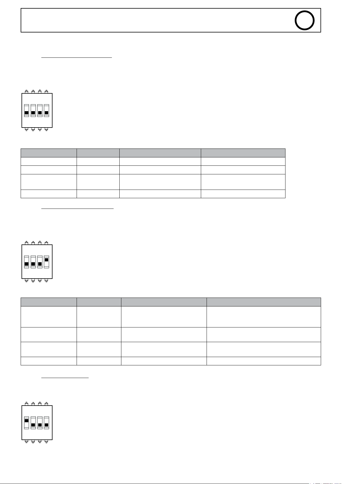
I. JOB mode - Without settings
All parameter settings stored in JOB mode are used (the values of inputs 1, 2 and 3 are, therefore, not taken into account).
DIP2-SWITCH 1 = OFF (Mode: JOB)
DIP2-SWITCH 4 = OFF (JOB LOCK)
1 2ON3 4
Table of adjustable values:
SAM-1A input Pin Connector Setting Value
INPUT_1 X20-1 - -
INPUT_2 X20-2 - -
INPUT_3 X20-4 Current type (Titanium only)
INPUT_4 X20-3 JOB number between 0 - 20
<5 V = DC
>5 V = AC
EN
II. JOB mode - SAM-1A settings
The welding current value (JOB mode’s Weld_Current parameter) is disregarded (the value is taken from the SAM-1A’s input).
DIP2-SWITCH 1 = OFF (Mode: JOB)
DIP2-SWITCH 4 = ON (JOB UNLOCK)
1 2ON3 4
Table of adjustable values:
SAM-1A input Pin Connector Setting Value
0 V = -6
INPUT_1 X20-1 ARC_LEN
INPUT_2 X20-2 WELD_CURRENT
INPUT_3 X20-4
INPUT_4 X20-3 JOB number between 0 - 20
Current type
(Titanium only)
0 V = minimum power source value
10 V = maximum power source value
5 V = 0
10 V = +6
<5 V = DC
>5 V = AC
III. TRACKING Mode
DIP2-SWITCH 1 = ON (Mode: TRACKING)
1 2ON3 4
36
Page 37
SAM-1A
Table of adjustable values:
SAM-1A input Pin Connector Setting Value
INPUT_1 X20-1 - -
INPUT_2 X20-2 WELD_CURRENT
INPUT_3 X20-4 Current type DC
INPUT_4 X20-3 Arc_Initiation
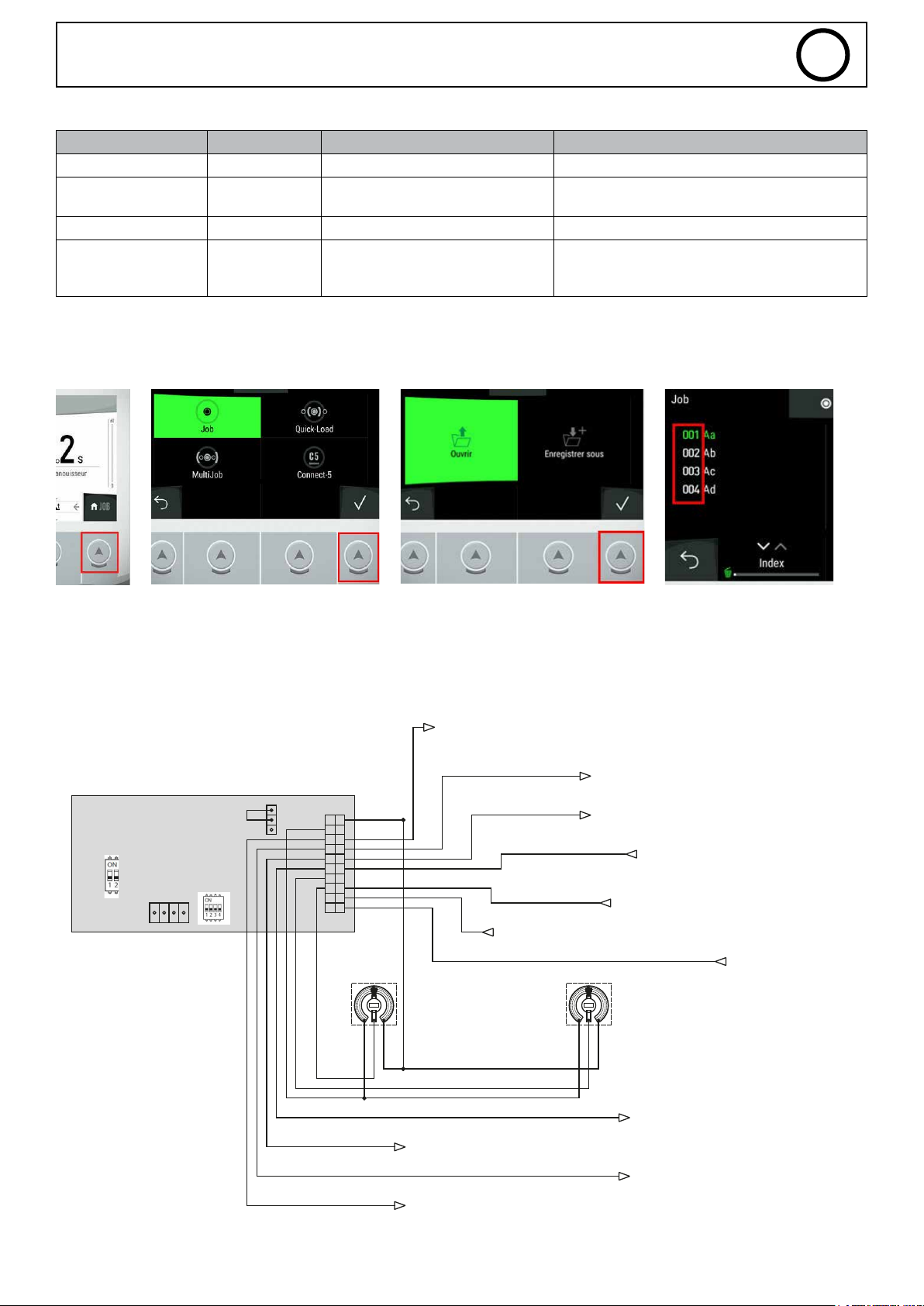
3. Where to nd the JOB number?
On the product’s man machine interface (MMI), complete the following steps:
1 2 3 4
0 V = minimum power source value
10 V = maximum power source value
< 1 V = HF
1 - 2 V = Lift
2 - 3 V = Touch_HF
EN
3. Example of diagram
TIG - JOB MODE - NO SETTINGS - SAFETY DEACTIVATED - INTERNAL 24V POWER SUPPLY
CN11T02
CON10T02
Outside the main welding stage
13-MAIN_ CURRENT
CN11T01
3-IN PUT_4
4-IN PUT_3
10K
JOB number setting
no JOB
0V =
0.5V = JOB 1
10V = JOB 20
0 =
In the main welding stage
1 =
19-START_PROCESS
0 = STOP
1 = START
10K
14-ARC_DETECT (0=PAS D ARC / 1=ARD DETECTE)
15-M_WELD_CURRENT
18-MMI_LOCK
0V = 0A
10V = 500A
16-WIRE_F EED (0=STOP / 1=START)
0 =
LOCK (multimeter mode)
UNLOCK (generator settings)
1 =
20-START_GAS
TITANIUM ONLY
Current type setting
<5V = DC
>5V = AC
NO ARC
0 =
ARC DETECTED
1 =
FEED OFF
0 =
FEED ON
1 =
0 =
1 =
GAS OFF
GAS ON
6-ERROR (0=OK / 1=ERREUR)
8-WELDING _PROCESS
0 =
1 =
OK
0 =
ERROR
1 =
NO WELDING
WELDING IN PROGRESS
5-M_WELD_VOLTAGE
7-AUTHO RISED_ START
0V = 0V
10V = 50V
0 =
WELDING PROHIBITED
1 =
AUTHORIZED WELDING
37
Page 38
SAM-1A
EN
APPENDIX 3 - SAM-1A EXAGON FLEX SETTINGS
1. SAM-1A I/O details ..........................................................................................................................................................38
a) Digital inputs .....................................................................................................................................................................38
b) Digital outputs ...................................................................................................................................................................38
2. Analog inputs/outputs ....................................................................................................................................................38
a) Analog outputs ...................................................................................................................................................................38
b) Analog input functions ........................................................................................................................................................ 38
I. CV mode - Generator settings ......................................................................................................................................38
II. CV mode - SAM-1A settings.......................................................................................................................................... 39
3. Examples of diagrams .....................................................................................................................................................39
1. SAM-1A I/O details
a) Digital inputs
The SAM-1A has 2 digital inputs (TOR) as detailed below:
Status
0 1
MMI_LOCK X20-18 Current-voltage multimeter
mode
RUN X20-19 Ban welding Authorize welding
Access to generator settings
b) Digital outputs
As well as the following 4 digital outputs (TOR) :
Status
0 1
Error X20-6 No error Error detected
Authorised_Start X20-7 Welding prohibited Approved for welding
Arc_Detect X20-14 Arc not detected Arc detection
2. Analog I/O details
a) Analog outputs :
The SAM-1A has two analogue outputs providing voltage and current measurement information with the following characteristics:
Voltage measurement (M_Weld_Voltage, X20-5) => ranges from 0V to 10V, corresponds to a measurement range of 0V to 50V
Current measurement (M_Weld_Current, X20-15) => varies from 0V to 10V, corresponding to a measurement range of 0A to 500A
b) Analog input functions :
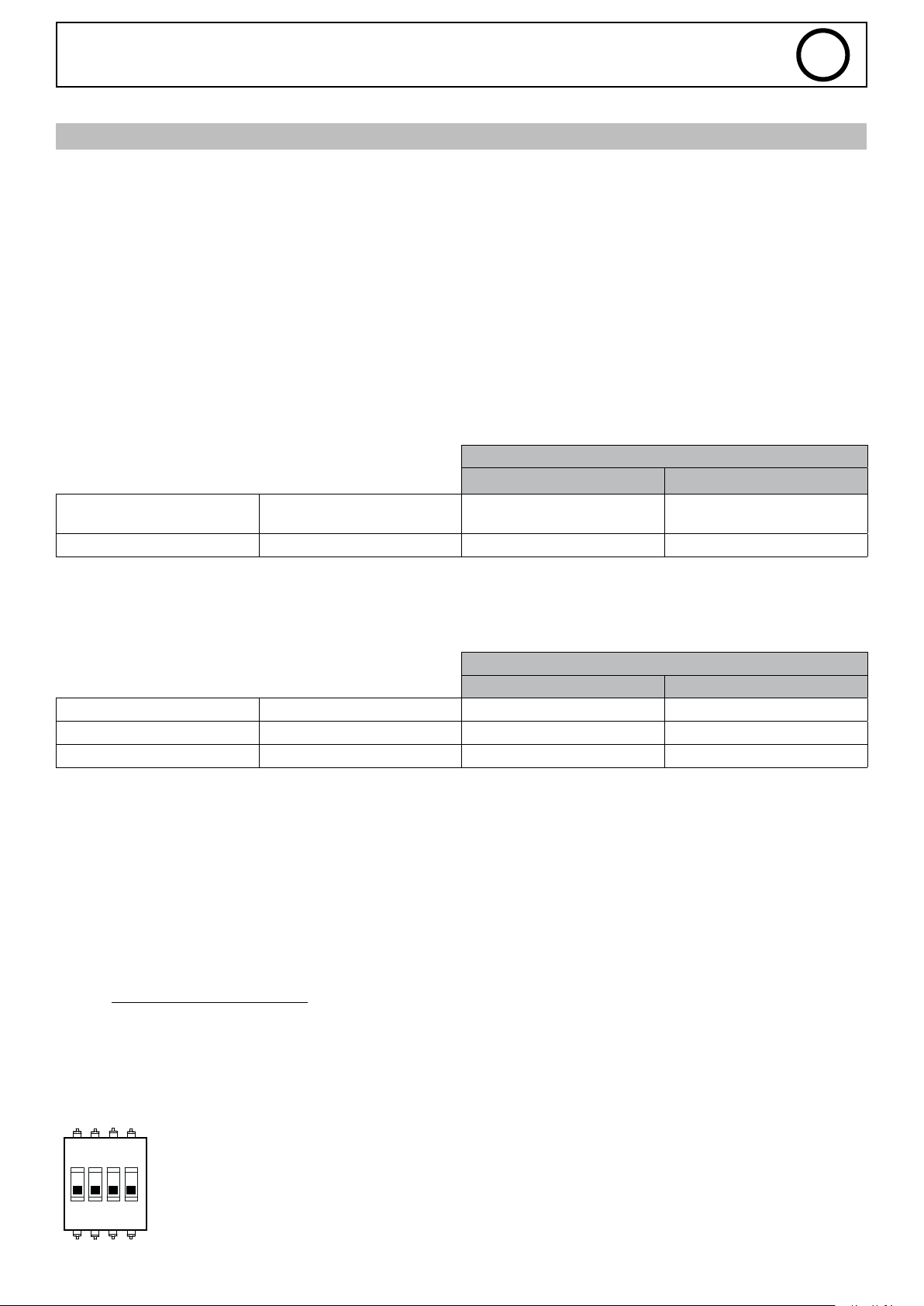
I. CV mode - Generator settings
The SAM-1A’s I_Start and Self parameter values are ignored.
DIP2-SWITCH 1=OFF (if ON: welding starts directly)
DIP2-SWITCH 2=OFF
DIP2-SWITCH 4=OFF (the I_Start and Self values are those of the generator)
1 2ON3 4
38
Page 39
SAM-1A
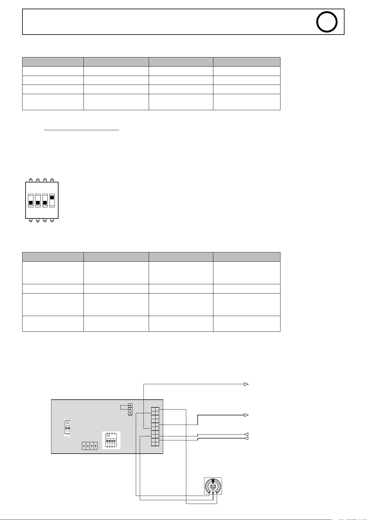
EXAGON - CV MODE - GENERATOR SETTING - SAFETY DEACTIVATED- INTERNAL 24V POWER SUPPLY
Table of adjustable values :
SAM1A input Parameter Value
INPUT_1 X20-1
INPUT_2 X20-2
INPUT_3 X20-4
INPUT_4 X20-3 Weld Voltage
II. CV mode - SAM-1A settings
The values of the SAM-1A parameters I_Start and Self are taken from the SAM-1A inputs.
DIP2-SWITCH 1=OFF (if ON: welding starts directly)
DIP2-SWITCH 2=OFF
DIP2-SWITCH 4=ON (the I_Start and Self values are those of the SAM-1A)
10V = 50V
EN
0V = 0V
1 2ON3 4
Table of adjustable values :
SAM1A input Parameter Value
INPUT_1 X20-1 I_Start
INPUT_2 X20-2
INPUT_3 X20-4 Self
INPUT_4 X20-3 Weld Voltage
3. Examples of diagrams
Conguration 1 : SAM-1A + EXAGON / CV MODE + GENERATOR SETTINGS
0V = 0A
5V = 200A
10V = 400A
0V = -9
5V = 0
10V = +9
0V = 0V
10V = 50V
5-M_WELD_VOLTAGE
Voltage measurement
0V = 0V
10V = 50V
CON10T02
CN11T02
CN11T01
Voltage adjustment
10K
0V = 0V
10V = 50V
15-M_WELD_CURRENT
18-MMI_LOCK
19-RUN
Current measurement
0V = 0A
10V = 500A
39
Page 40
SAM-1A
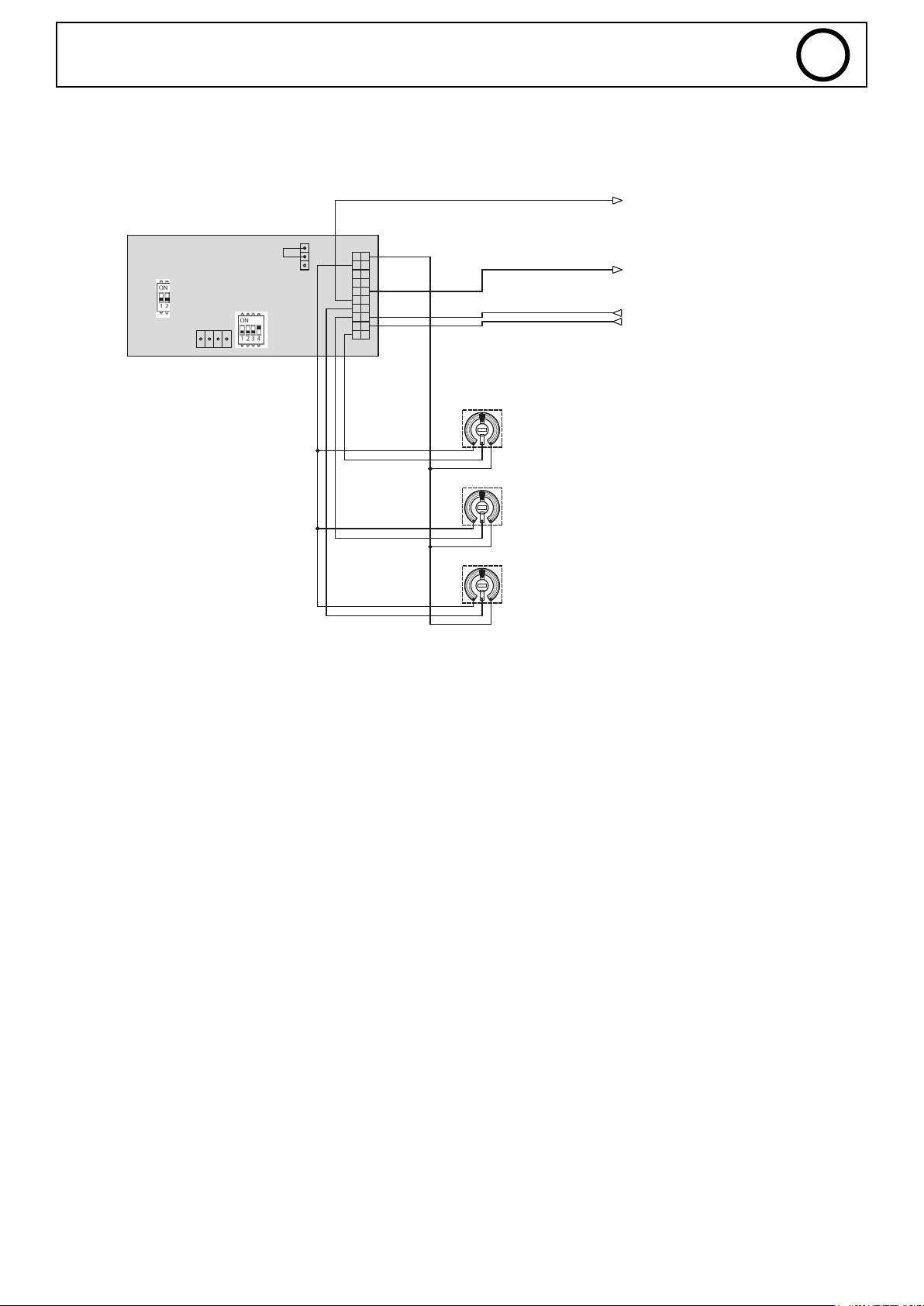
Conguration 2 : SAM-1A + EXAGON / MODE CV MODE + SAM-1A SETTINGS
EXAGON - CV MODE - SAM-1A SETTING - SAFETY DEACTIVATED- INTERNAL 24V POWER SUPPLY
5-M_WELD_VOLTAGE
EN
Voltage measurement
0V = 0V
10V = 50V
CON10T02
CN11T02
CN11T01
10K
10K
10K
Setting I_Start
0V = 0A
5V = 200A
10V = 400A
Setting Self
0V = -9
5V = 0
10V = +9
Setting Voltage
0V = 0V
10V = 50V
15-M_WELD_CURRENT
18-MMI_LOCK
19-RUN
Current measurement
0V = 0A
10V = 500A
40
SAS GYS
1, rue de la Croix des Landes
CS 54159
53941 SAINT-BERTHEVIN Cedex
France
 Loading...