

GYS MANUAL PLASMA TORCH MT-125 - 12m - NO CONSUMABLES, MANUAL PLASMA TORCH MT-125 - 6m - NO CONSUMABLES User guide [pt]

FR
2-6 / 37-40
MT-125 / AT-125
EN
DE
ES
RU
IT
NL
V7_10/05/2021
7-11 / 37-40
12-16 / 37-40
17-21 / 37-40
22-26 / 37-40
27-31 / 37-40
32-36 / 37-40
www.gys.fr
MT-125 / AT-125
FR
AVERTISSEMENTS - RÈGLES DE SÉCURITÉ
CONSIGNE GÉNÉRALE
Ces instructions doivent être lues et bien comprises avant toute opération.
Toute modication ou maintenance non indiquée dans le manuel ne doit pas être entreprise.
Tout dommage corporel ou matériel dû à une utilisation non-conforme aux instructions de ce manuel ne pourra être retenu à la charge du fabricant.
En cas de problème ou d’incertitude, veuillez consulter une personne qualiée pour manier correctement l’installation.
PROTECTION INDIVIDUELLE ET DES AUTRES
Le coupage peut être dangereux et causer des blessures graves voire mortelles.
Le coupage expose les individus à une source dangereuse de chaleur, de rayonnement lumineux de l’arc, de champs électromagnétiques (attention
au porteur de pacemaker), de risque d’électrocution, de bruit et d’émanations gazeuses.
Pour bien se protéger et protéger les autres, respecter les instructions de sécurité suivantes :
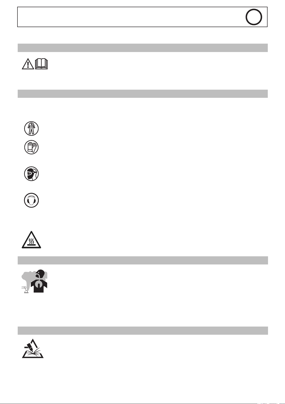
An de se protéger de brûlures et rayonnements, porter des vêtements sans revers, isolants, secs, ignifugés et en bon état, qui
couvrent l’ensemble du corps.
Utiliser des gants qui garantissent l’isolation électrique et thermique.
Utiliser une protection de coupage et/ou une cagoule de coupage d’un niveau de protection susant (variable selon les applications).
Protéger les yeux lors des opérations de nettoyage. Les lentilles de contact sont particulièrement proscrites.
Il est parfois nécessaire de délimiter les zones par des rideaux ignifugés pour protéger la zone de coupage des rayons de l’arc, des
projections et des déchets incandescents.
Informer les personnes dans la zone de coupage de ne pas xer les rayons de l’arc ni les pièces en fusion et de porter les vêtements
adéquats pour se protéger.
Utiliser un casque contre le bruit si le procédé de coupage atteint un niveau de bruit supérieur à la limite autorisée (de même pour
toute personne étant dans la zone de coupage).
Tenir à distance des parties mobiles (ventilateur) les mains, cheveux, vêtements.
Ne jamais enlever les protections carter du groupe froid lorsque la source de courant de coupage est sous tension, le fabricant ne
pourrait être tenu pour responsable en cas d’accident.
Les pièces qui viennent d’être coupées sont chaudes et peuvent provoquer des brûlures lors de leur manipulation. Lors d’intervention
d’entretien sur la torche, il faut s’assurer que celle-ci soit susamment froide en attendant au moins 10 minutes avant toute
intervention. Le groupe froid doit être allumé lors de l’utilisation d’une torche refroidie eau an d’être sûr que le liquide ne puisse
pas causer de brûlures.
Il est important de sécuriser la zone de travail avant de la quitter an de protéger les personnes et les biens.
FUMÉES DE COUPAGE ET GAZ
Les fumées, gaz et poussières émis par le coupage sont dangereux pour la santé. Il faut prévoir une ventilation susante et un
apport d’air est parfois nécessaire. Un masque à air frais peut être une solution en cas d’aération insusante.
Vérier que l’aspiration est ecace en la contrôlant par rapport aux normes de sécurité.
Attention, le coupage dans des milieux de petites dimensions nécessite une surveillance à distance de sécurité. Par ailleurs le coupage de certains
matériaux contenant du plomb, cadmium, zinc ou mercure voire du béryllium peuvent être particulièrement nocifs, dégraisser également les pièces
avant de les couper.
Les bouteilles doivent être entreposées dans des locaux ouverts ou bien aérés. Elles doivent être en position verticale et maintenues à un support ou
sur un chariot. Le coupage doit être proscrit à proximité de graisse ou de peinture.
RISQUE DE FEU ET D’EXPLOSION
Protéger entièrement la zone de coupage, les matières inammables doivent être éloignées d’au moins 11 mètres.
Un équipement anti-feu doit être présent à proximité des opérations de coupage.
Attention aux projections de matières chaudes ou d’étincelles et même à travers des ssures, elles peuvent être source d’incendie ou d’explosion.
Éloigner les personnes, les objets inammables et les containers sous pressions à une distance de sécurité susante.
Le coupage dans des containers ou des tubes fermés est à proscrire et dans le cas où ils sont ouverts il faut les vider de toute matière inammable
ou explosive (huile, carburant, résidus de gaz …).
Les opérations de meulage ne doivent pas être dirigées vers la source de courant de coupage ou vers des matières inammables.
2

MT-125 / AT-125
FR
SÉCURITÉ ÉLECTRIQUE
Une décharge électrique peut être une source d’accident grave direct ou indirect, voire mortel.
Ne jamais toucher les parties sous tension de la torche car celle-ci est branchée au circuit de coupage.
Ne pas toucher en même temps la torche et la pince de masse.
Toujours utiliser des vêtements secs et en bon état pour s’isoler du circuit de coupage. Portez des chaussures isolantes, quel que soit le milieu où
vous travaillez.
PRÉCAUTION D’EMPLOI
N’enroulez jamais la torche autour de votre corps.
Ne pas utiliser la torche pour déplacer la source de courant de coupage.
La torche doit être totalement déroulée an d’éviter toute surchaue.
Arrêtez le générateur de courant après que la torche soit refroidie et avant chaque entretien et avant de remplacer ou contrôler les pièces d’usure.
Contrôlez régulièrement l’état de la torche. Si celle-ci est endommagée, elle doit être remplacée.
DESCRIPTION GÉNÉRALE
SPÉCIFICATIONS
Les torches MT-125 sont destinées au procédé de coupage PLASMA manuel.
La torche AT-125 est destinée au procédé de coupage PLASMA automatisé.
DONNÉES TECHNIQUES
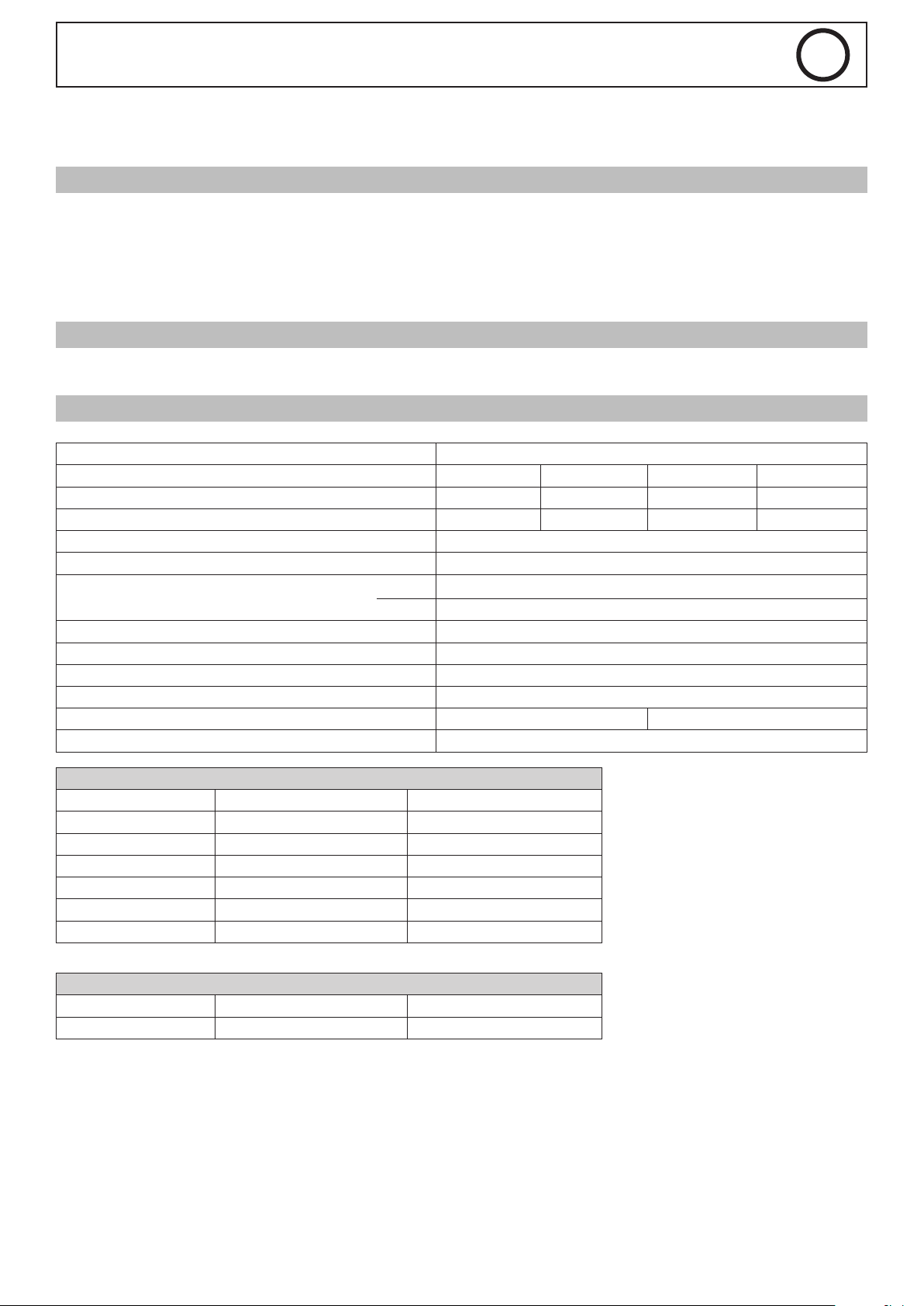
Compatibilité avec les sources de courant de coupage CUTTER 85A / 125A - NEOCUT 105 / 125
Désignation MT-125 6 m MT-125 12 m AT-125 6 m AT-125 12 m
Référence 039506 039513 038479 039520
Longueur 6 m 12 m 6 m 12 m
Tension d’amorçage 500V max
Courant max assigné 125 A
Facteur de marche à 40°C
Type de gaz air
Refroidissement de la torche air
Plage de température ambiante en coupage -10 -> +40°C
Plage de température ambiante de transport ou stockage -10 -> +55°C
Caractérisitque du switch (trigger) 0.5 A / 48 V DC -
Norme appliquée EN60974-7: 2013
COUPAGE
COURANT Torche 6 m Torche 12 m
45A FINE CUT 5.0 bar - 220 l/min 5.6 bars - 220 l/min
45 A 5.0 bar – 215 l/min 5.6 bar – 215 l/min
65 A 5.0 bar – 220 l/min 5.6 bar – 220 l/min
85 A 5.0 bar – 250 l/min 5.6 bar – 250 l/min
105 A 5.0 bar – 285 l/min 5.6 bar – 285 l/min
125 A 5.5 bar – 305 l/min 6.2 bar – 305 l/min
100% 100 A
60% 125 A
GOUGEAGE
COURANT Torche 6 m Torche 12 m
85A - 125A 4.0 bar 4.5 bar
3

MT-125 / AT-125
039513 - 12 m
039513 - 12 m
FR
INSTALLATION
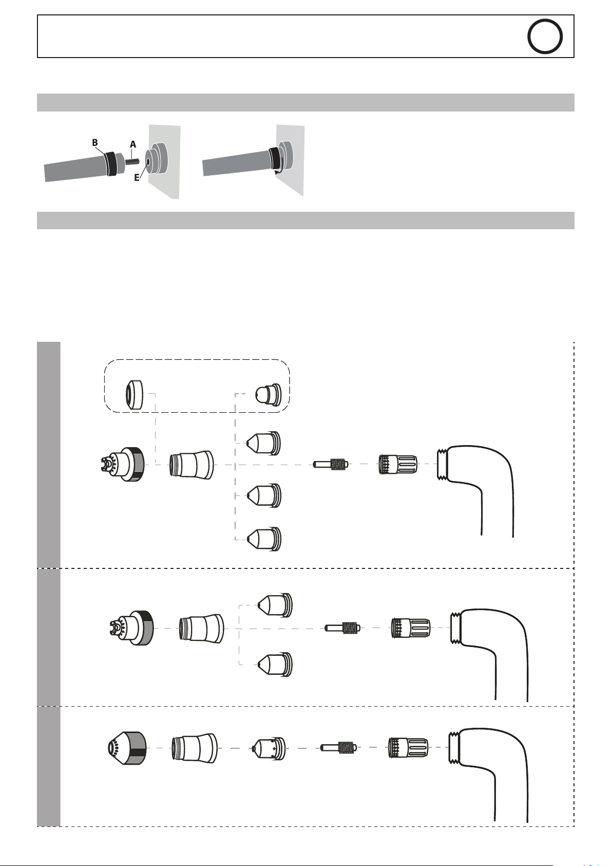
EXIGENCE DE RACCORDEMENT DE LA TORCHE
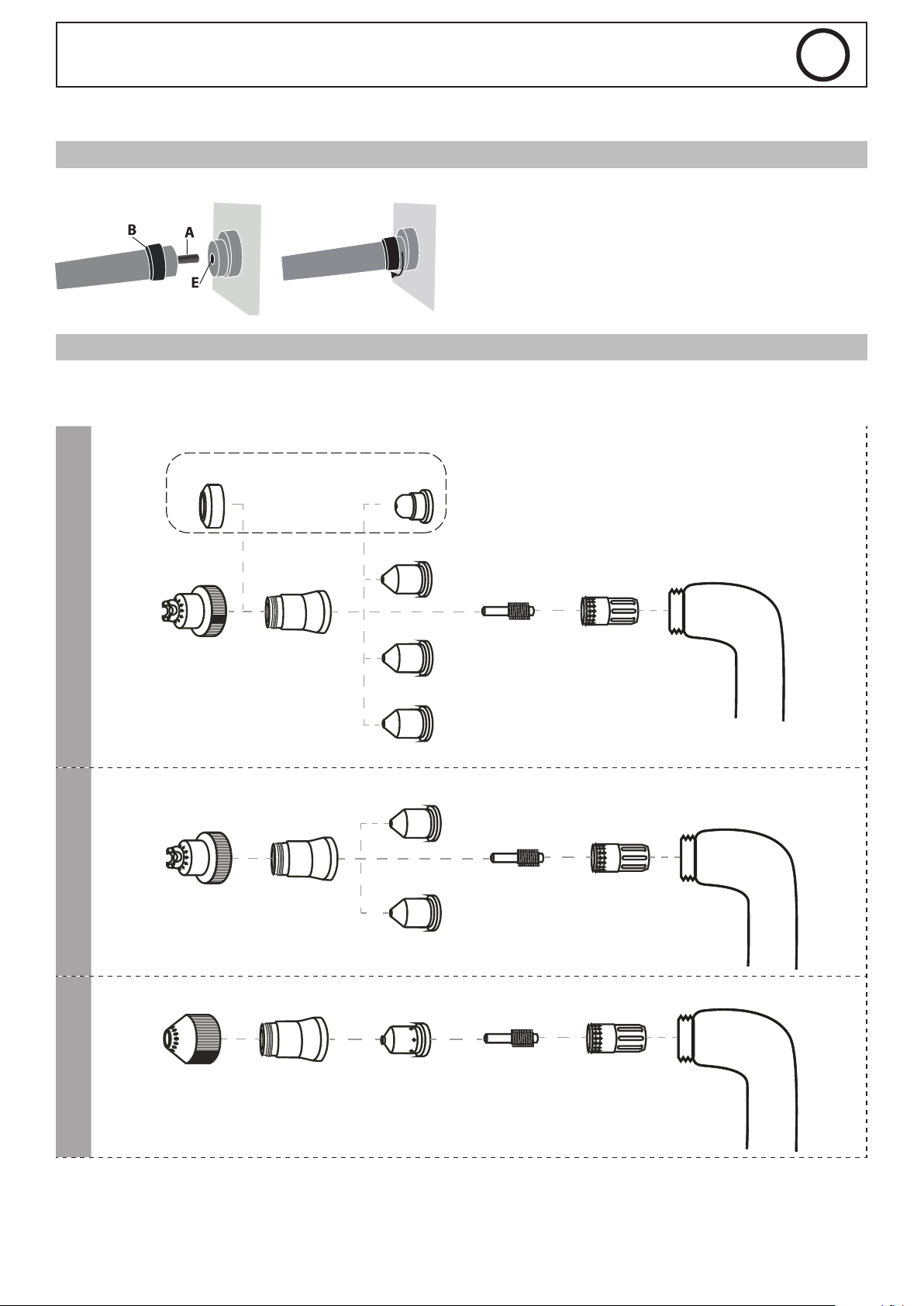
Le générateur de coupage doit être mis hors tension.
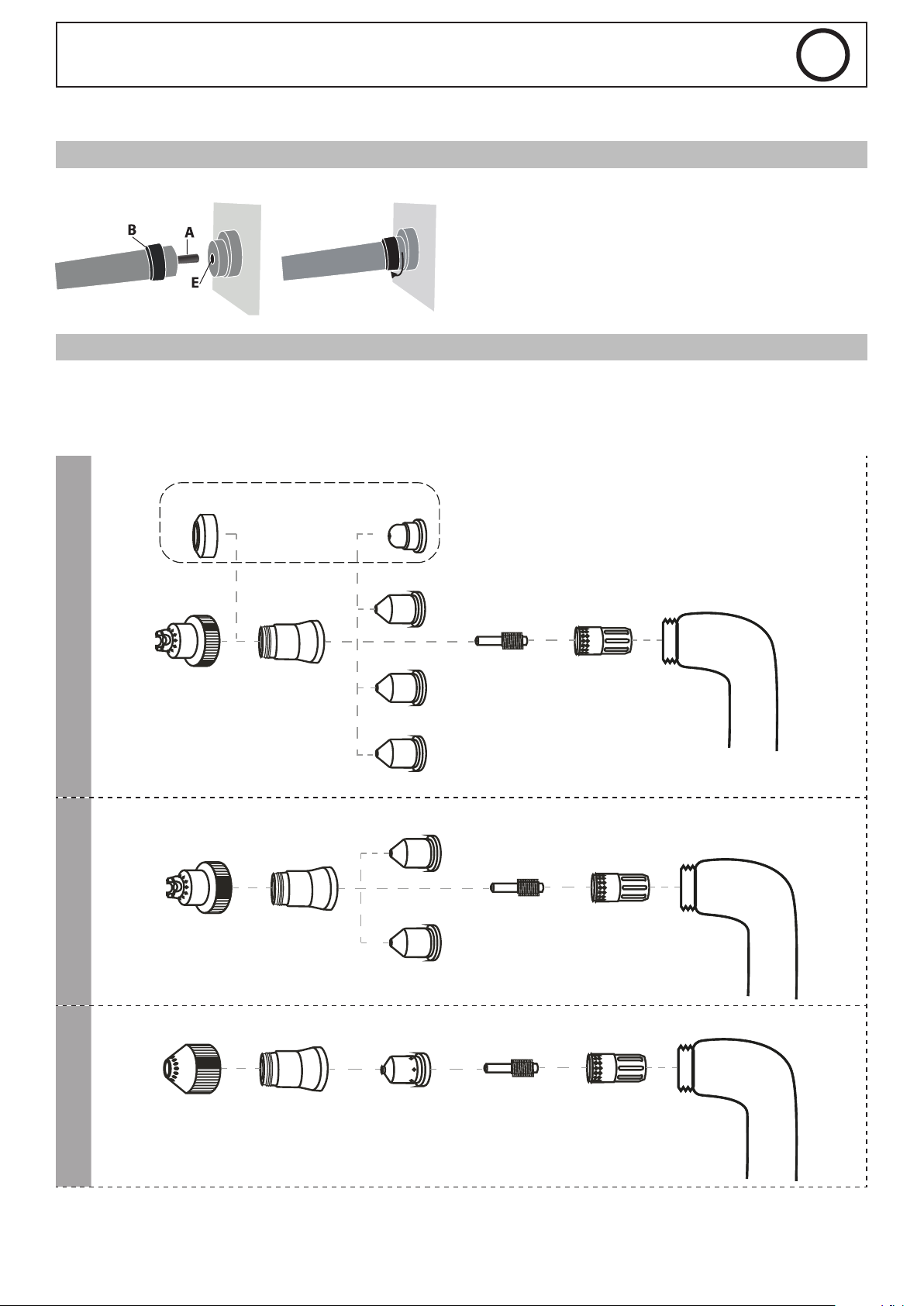
Insérer le connecteur de la torche (A) dans le logement femelle (E) et
visser la partie B. Attention à bien serrer la torche.
Pour retirer la torche, dévisser de la même manière que ci-dessus.
ÉQUIPEMENT DES TORCHES
La torche doit être équipée avec les bons consommables, choisis en fonction de l’application et du courant réglé.
Un mauvais choix de consommable provoquera des défauts de coupage, l’usure prématurée des consommables et voire un dysfonctionnement de
l’ensemble. La torche est livrée avec un pot de graisse silicone an de limiter l’usure du joint et le grippage des parties métalliques. Il est conseillé
d’appliquer cette graisse régulièrement.
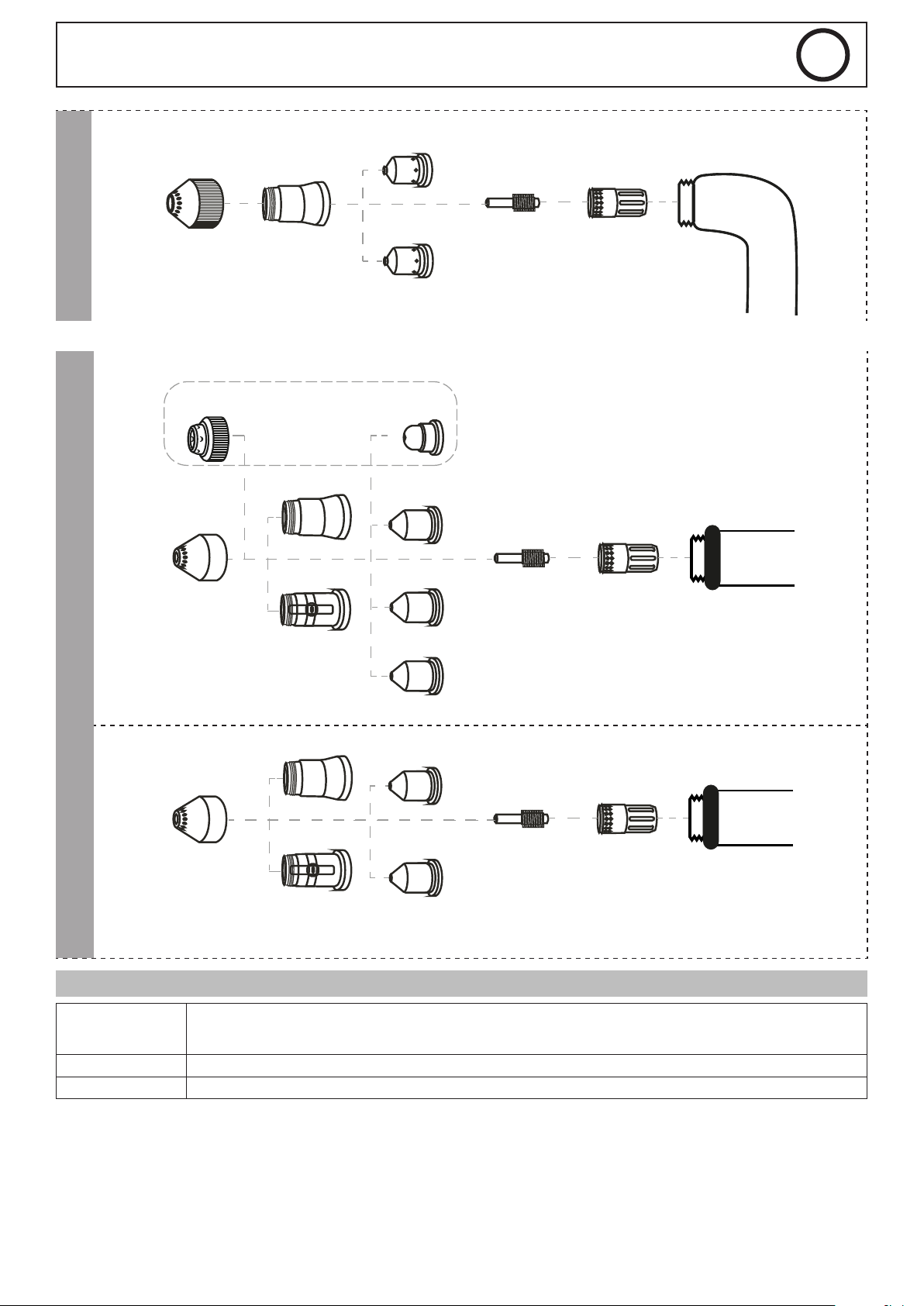
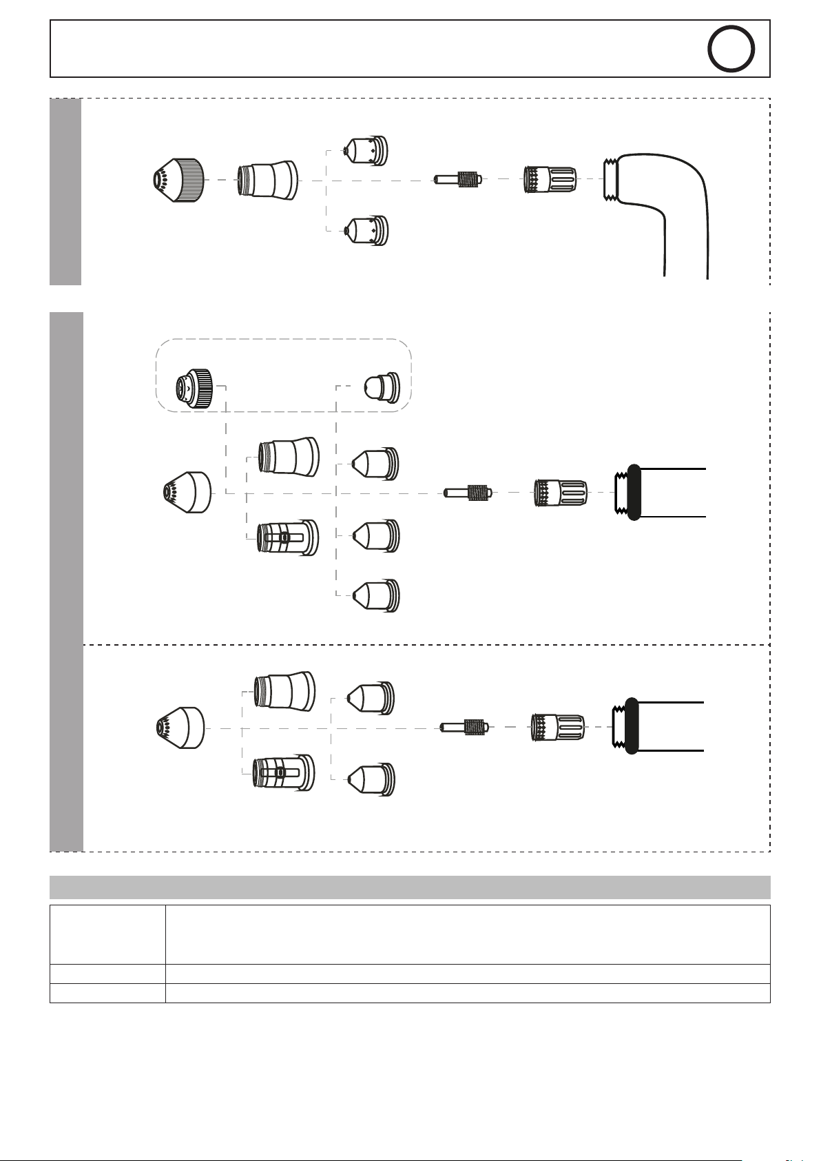
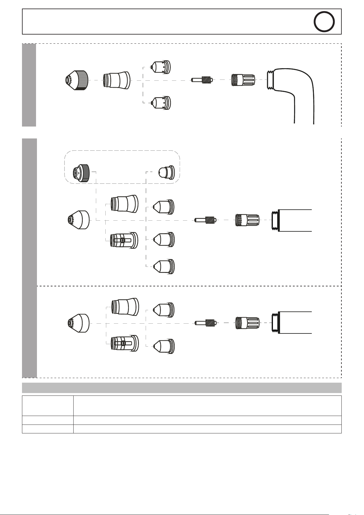
MT-125 – COUPAGE-GOUGEAGE :
PRECISION CUT
COUPE
COUPE
039322 (x1)
45A
039230 (x1)
Patin
039247 (x1)
Patin
039216 (x1)
Buse de
protection
039223 (x1)
Buse de
protection
039315 (x5)
45A
039162 (x5)
45A
039179 (x5)
65A
039186 (x5)
85A
Tuyère
029193 (x5)
105A
039209 (x5)
125A
Tuyère
039131 (x1)039155 (x5)
Électrode Diuseur
039506 - 6 m
039513 - 12 m
039148 (x1)039155 (x5)
Électrode Diuseur
039506 - 6 m
039261 (x5)
65-85A
Tuyère
039131 (x1)039155 (x5)
Électrode Diuseur
GOUGEAGE
039254 (x1)
Patin
039216 (x1)
Buse de
protection
039506 - 6 m
4
039513 - 12 m
039254 (x1)
039223 (x1)
MT-125 / AT-125
029278 (x5)
105A
FR
039148 (x1)039155 (x5)
GOUGEAGE
AT-125 – COUPAGE :
COUPE
Patin
037496 (x1)
45A
039292 (x1)
Patin
Buse de
protection
PRECISION CUT
039216 (x1)
039339 (x1)
ohmic
Buse de
protection
029285 (x5)
125A
Tuyère
039315 (x5)
45A
039162 (x5)
45A
039179 (x5)
65A
039186 (x5)
85A
Tuyère
Électrode Diuseur
039506 - 6 m
039131 (x1)039155 (x5)
Électrode Diuseur
038479 - 6 m
039520 - 12 m
039223 (x1)
039308 (x1)
039445 (x1)
Patin
039193 (x5)
105A
039209 (x5)
125A
039148 (x1)039155 (x5)
Électrode Diuseur
038479 - 6 m
039520 - 12 m
ohmic
Buse de
Tuyère
protection
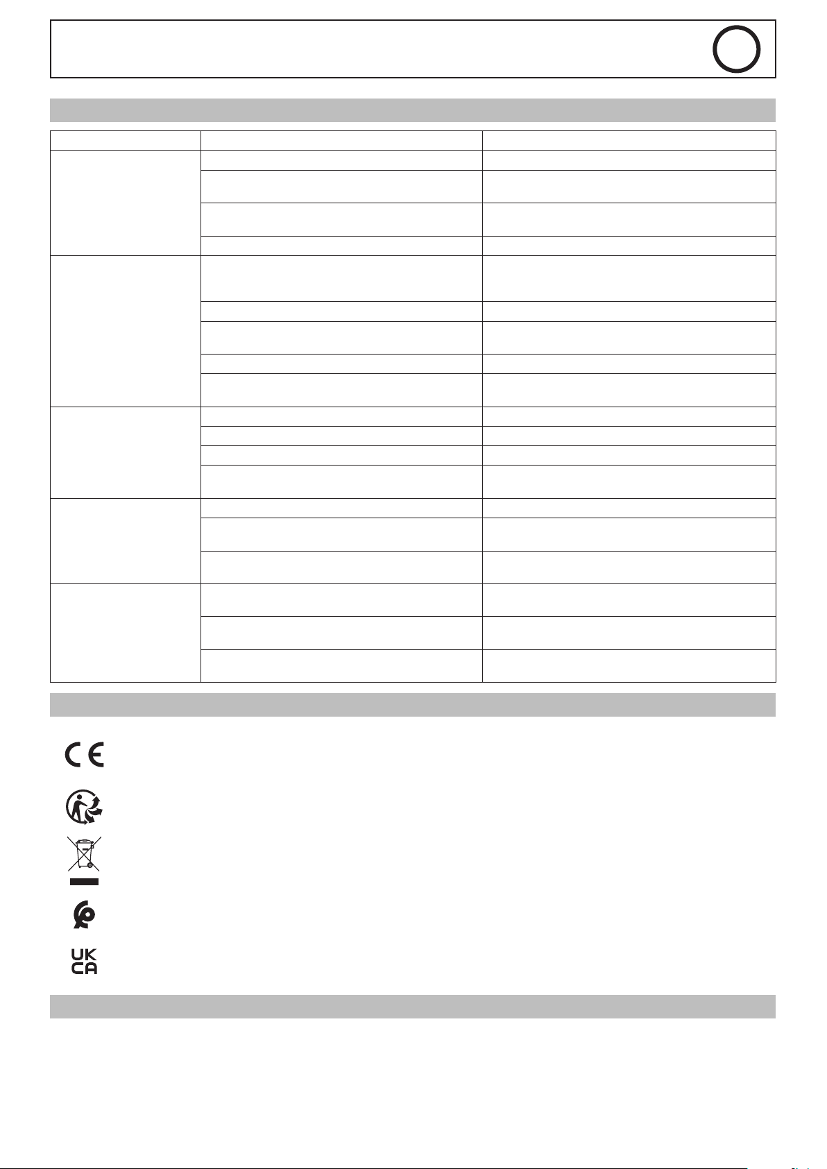
SOURCE DE DÉFAUT
CONSOMMABLES
BUSE Serrer la buse de sorte que toutes les pièces soient bien bloquées. La tuyère ne doit pas tourner facilement.
GAZ Utiliser de l’air comprimé avec ltration de l’huile et de l’eau.
Les consommables sont des éléments d’usure, il est important de savoir à quels moments les changer.
Visuellement : état des consommables fondu ou abîmé, trous de tuyères >1.5mm, électrodes usées, patins fondus…
Pratiquement : perte de performance de coupage, amorçage sur pièce dicile, etc.
5

MT-125 / AT-125
ANOMALIES, CAUSES, REMÈDES
SYMPTÔME CAUSES POSSIBLE REMÈDE
Torche mal connectée au générateur. Vérier la connexion de la torche sur le générateur.
Pression d’air comprimée inappropriée. Ajuster la pression de l’air à la valeur recommandée.
Pas d’amorçage d’arc.
Interruption de l’arc de
coupe.
Usure prématurée des
consommables.
Excès de bavures sous la
pièce après découpe.
Saignée non perpendiculaire
à la surface de la tôle.
Pièce consommable manquante (buse, tuyère, électrode, diuseur).
Défaut de montage des consommables. L’électrode n’est pas en contact avec la tuyère.
Pince de masse mal connectée (Si interruption après
quelques secondes de coupe).
Vitesse d’avance de coupe inappropriée. Ajuster la vitesse de coupe.
Distance entre la pièce à découper et la buse de la
torche trop importante.
Coupure d’alimentation en air comprimée. Vérier l’alimentation en air comprimée
Consommable endommagé dans la torche.
Pression d’air insusante. Ajuster la pression d’air.
Vitesse d’avance de coupe trop rapide. Ajuster la vitesse de coupe
Présence d’impuretés ou d’humidité dans l’air compri-
mée.
Surface de la pièce à découper souillée. Nettoyer et décaper la surface de la tôle à découper.
Vitesse d’avance de coupe trop rapide. Ajuster la vitesse de coupe
Pression d’air comprimée inappropriée. Ajuster la pression de l’air à la valeur recommandée
Valeur du courant de découpe trop faible par rapport à
l’épaisseur de la pièce à découper.
Torche non maintenue perpendiculaire à la surface de
la pièce à découper.
Consommables mal montés dans la torche (buse non
serrée…).
Valeur du courant de découpe trop faible par rapport à
l’épaisseur de la pièce à découper.
Remplacer les pièces manquantes.
Vérier que la pince de masse est bien connectée sur
une surface décapée de la tôle à découper.
Rapprocher la torche de la pièce.
Inspecter les pièces consommables de la torche et procéder à leur remplacement.
Vérier le ltre à air sur le générateur.
Ajuster la valeur du courant de découpe sur le générateur.
Améliorer le maintien de la torche.
Réajuster le montage et le serrage des consommables.
Ajuster la valeur du courant de découpe sur le générateur.
FR
CERTIFICATION ET CONSIGNE DE TRI
Matériel conforme aux directives européennes. La déclaration UE de conformité est disponible sur notre site (voir à la page de
couverture).
Produit recyclable qui relève d’une consigne de tri.
Ce matériel fait l’objet d’une collecte sélective selon la directive européenne 2012/19/UE. Ne pas jeter dans une poubelle domes-
tique !
Matériel conforme aux normes Marocaines. La déclaration Cم (CMIM) de conformité est disponible sur notre site.
Matériel conforme aux exigences britanniques. La déclaration de conformité britannique est disponible sur notre site (voir à la
page de couverture).
CONDITIONS DE GARANTIE FRANCE
La garantie couvre tous défauts ou vices de fabrication pendant 2 ans, à compter de la date d’achat (pièces et main d’oeuvre).
La garantie ne couvre pas :
• Toutes autres avaries dues au transport.
• L’usure normale des pièces (Ex. : câbles, pinces, etc.).
• Les incidents dus à un mauvais usage (erreur d’alimentation, chute, démontage).
• Les pannes liées à l’environnement (pollution, rouille, poussière).
En cas de panne, retourner l’appareil à votre distributeur, en y joignant :
- un justicatif d’achat daté (ticket de sortie de caisse, facture….)
- une note explicative de la panne.
6

MT-125 / AT-125
EN
WARNING - SAFETY RULES
GENERAL INSTRUCTIONS
Read and understand the following safety recommendations before using or servicing the unit.
Any change or servicing that is not specied in the instruction manual must not be undertaken.
The manufacturer is not liable for any injury or damage caused due to non-compliance with the instructions featured in this manual.
In the event of problems or uncertainties, please consult a qualied person to handle the installation properly.
PROTECTION OF THE INDIVIDUALS
Plasma cutting can be dangerous and can cause serious and even fatal injuries.
Cutting exposes the user to dangerous heat, arc rays, electromagnetic elds, noise, gas fumes, and electrical shocks. People wearing pacemakers are
advised to consult with their doctor before using this device.
To protect oneself as well as the other, ensure the following safety precautions are taken:
In order to protect you from burns and radiations, wear clothing without cus. These clothes must be insulated, dry, reproof and
in good condition, and cover the whole body.
Wear protective gloves which guarantee electrical and thermal insulation.
Use sucient cutting protective gear for the whole body: hood, gloves, jacket, trousers... (varies depending on the application/
operation). Protect the eyes during cleaning operations. Do not operate whilst wearing contact lenses.
It may be necessary to install reproof welding curtains to protect the area against arc rays, weld spatters and sparks.
Inform the people around the working area to never look at the arc nor the molten metal, and to wear protective clothes.
Ensure ear protection is worn by the operator if the work exceeds the authorised noise limit (the same applies to any person in
the welding area).
Stay away from moving parts (e.g. engine, fan...) with hands, hair, clothes etc...
Never remove the safety covers from the cooling unit when the machine is plugged in - The manufacturer is not responsible for
any accident or injury that happens as a result of not following these safety precautions.
The pieces that have just been welded are hot and may cause burns when manipulated. During maintenance work on the torch or
the electrode holder, you should make sure it’s cold enough and wait at least 10 minutes before any intervention. The cooling unit
must be on when using a water cooled torch in order to ensure that the liquid does not cause any burns.
ALWAYS ensure the working area is left as safe and secure as possible to prevent damage or accidents.
CUTTING FUMES AND GAS
The fumes, gases and dust produced during cutting are hazardous. It is mandatory to ensure adequate ventilation and/or
extraction to keep fumes and gases away from the work area. An air fed helmet is recommended in cases of insucient air supply
in the workplace.
Check that the air intake is in compliance with safety standards.
Care must be taken when cutting in small areas, and the operator will need supervision from a safe distance. Cutting certain pieces of metal containing
lead, cadmium, zinc, mercury or beryllium can be extremely toxic. The user will also need to degrease the workpiece before cutting.
Gas cylinders must be stored in an open or ventilated area. The cylinders must be in a vertical position secured to a support or trolley.
Do not cut in areas where grease or paint are stored.
FIRE AND EXPLOSION RISKS
Protect the entire cutting area. Compressed gas containers and other inammable material must be moved to a minimum safe
distance of 11 meters.
A re extinguisher must be readily available.
Be careful of spatter and sparks, even through cracks. It can be the source of a re or an explosion.
Keep people, ammable objects and containers under pressure at a safe distance.
Cutting of sealed containers or closed pipes should not be undertaken, and if opened, the operator must remove any inammable or explosive
materials (oil, petrol, gas...).
Grinding operations should not be directed towards the device itself, the power supply or any ammable materials.
ELECTRIC SAFETY
An electric shock can be a source of a direct or indirect, or even fatal, serious accident.
7
MT-125 / AT-125
Never touch the live parts of the torch as it is connected to the cutting circuit.
Do not touch the torch and the ground clamp at the same time.
Always use dry, well-maintained clothing to isolate yourself from the cutting circuit. Wear insulating shoes, no matter where you work.
EN
PRECAUTION FOR USE
Never wrap the cutting leads around your body.
Do not use the cables or torch to move the machine.
The torch must be fully uncoiled to prevent overheating.
Switch o the generator after the torch is cooled and before each maintenance and before replacing or control wearing parts.
Regularly check the condition of the torch. If damaged, the torch must be replaced.
GENERAL DESCRIPTION
SPECIFICATIONS
MT-125 torches are designed for manual PLASMA cutting.
AT-125 torches are designed for automated PLASMA cutting.
TECHNICAL SPECIFICATIONS
Compatible with cutting machines CUTTER 85A / 125A - NEOCUT 105 / 125
Designation MT-125 - 6 m MT-125 - 12 m AT-125 - 6 m AT-125 - 12 m
Part number 039506 039513 038479 039520
Length 6 m 12 m 6 m 12 m
Starting voltage 500V max
Max allocated current 125 A
Duty cycle at 40°C
Type de gas air
Torch cooling air
Range of ambient temperature in cutting -10 -> +40°C
Range of ambient temperature in transport or storage -10 -> +55°C
Specications of the switch (trigger) 0.5 A / 48 V DC Applied standard EN60974-7: 2013
100% 100 A
60% 125 A
CUTTING
COURANT Torch 6 m Torch 12 m
45A FINE CUT 5.0 bar - 220 l/min 5.6 bars - 220 l/min
45 A 5.0 bar – 215 l/min 5.6 bar – 215 l/min
65 A 5.0 bar – 220 l/min 5.6 bar – 220 l/min
85 A 5.0 bar – 250 l/min 5.6 bar – 250 l/min
105 A 5.0 bar – 285 l/min 5.6 bar – 285 l/min
125 A 5.5 bar – 305 l/min 6.2 bar – 305 l/min
GOUGING
CURRENT Torch 6 m Torch 12 m
85A - 125A 4.0 bar 4.5 bar
8
MT-125 / AT-125
039513 - 12 m
039513 - 12 m
SET UP
TORCH CONNECTION REQUIREMENT
The cutting machine must be switched o.
Insert the torch connector (A) in the female connector (E) and screw the
part B. Make sure the torch is tight enough.
To remove the torch, unscrew as shown below.
TORCHES EQUIPMENT
The torch must be tted with the appropriate consumables, selected based on the application and selected current.
Using the wrong consumables will result in poor cutting, excessive use of consumables and possibly prevent the machine from working.
MT-125 – CUTTING-GOUGING :
PRECISION CUT
EN
CUT
CUT
039322 (x1)
45A
039230 (x1)
Shield
039247 (x1)
Shield
039216 (x1)
Protective
shroud
039223 (x1)
Protective
shroud
039315 (x5)
45A
039162 (x5)
45A
039179 (x5)
65A
039186 (x5)
85A
Tailpipe
029193 (x5)
105A
039209 (x5)
125A
Tailpipe
039131 (x1)039155 (x5)
Electrode Diuser
039506 - 6 m
039513 - 12 m
039148 (x1)039155 (x5)
Electrode Diuser
039506 - 6 m
GOUGING
039254 (x1)
Shield
039216 (x1)
Protective
shroud
039261 (x5)
65-85A
Tailpipe
039131 (x1)039155 (x5)
Electrode Diuser
039506 - 6 m
9

039513 - 12 m
039254 (x1)
039223 (x1)
MT-125 / AT-125
029278 (x5)
105A
EN
039148 (x1)039155 (x5)
GOUGING
AT-125 – CUTTING :
CUT
Shield
037496 (x1)
45A
039292 (x1)
Shield
Protective
shroud
PRECISION CUT
039216 (x1)
039339 (x1)
ohmic
Protective
shroud
029285 (x5)
125A
Tailpipe
039315 (x5)
45A
039162 (x5)
45A
039179 (x5)
65A
039186 (x5)
85A
Tailpipe
Electrode Diuser
039506 - 6 m
039131 (x1)039155 (x5)
Electrode Diuser
038479 - 6 m
039520 - 12 m
039223 (x1)
039308 (x1)
039445 (x1)
Shield
039193 (x5)
105A
039209 (x5)
125A
039148 (x1)039155 (x5)
Electrode Diuser
038479 - 6 m
039520 - 12 m
ohmic
Protective
Tailpipe
shroud
COMMON DEFECTS ROOT CAUSE
Consumables
Nozzle The nozzle shall be properly tightened so that all parts are correctly xed. The nozzle shall not be easily turned.
Gas Use compressed air with oil and water ltration.
Consumables are wear parts, it s important to know when to replace them.
Visually: welded or damaged consumables, tip hole larger than 1.5mm, weared electrode, welded pads...
Consequencies: loss of cutting performance, arc striking diculties...
10

MT-125 / AT-125
TROUBLESHOOTING
SYMPTOMS POSSIBLE CAUSES SOLUTIONS
Torch incorrectly plugged on the generator. Check the torch connection on the generator.
Unsuitable pressure of compressed air. Set the air pressure to the recommended value.
No arc striking
Interruption of cutting arc
Untimely wear of consumables
Excess of barbs underneath
the parts after the cutting
The cut groove is not
perpendicular to the metal
sheet surface
Missing consumable part (nozzle, tip, electrode,
diuser)
Assembly defect of consumables.
Earth clamp not properly clamped (if interruption after
a few seconds of cutting)
Unsuitable cutting speed. Adjust the cutting speed.
Too important distance between the torch nozzle and
the part to be cut.
Disruption of compressed air feeding. Check the feeding of compressed air.
Damaged consumable inside the torch. Inspect the torch consumable parts and replace them.
Insucient air pressure. Adjust the air pressure.
Too fast cutting speed. Adjust the cutting speed.
Impurities or humidity in compressed air. Check the air lter on the generator.
Surface of the part to be cut too dirty. Clean and strip the surface of the metal sheet.
Cutting speed too fast. Adjust the cutting speed.
Unsuitable pressure of compressed air. Adjust the air pressure to the recommended value.
Insucient setting of the cutting current value accor-
ding to the thickness of the metal part to be cut.
The torch is not kept perpendicular to the surface of
the part to be cut.
Consumable not properly assembled inside the torch
(untightened nozzle…)
The setting of cutting current is too small according to
the thickness of the part to be cut.
Replace the missing parts.
Electrode is not in contact with the tip. Rectify the
assembly of all consumables.
Check that the earth clamp is connected on a properly
stripped area of the metal sheet.
Keep the torch close to the part.
Adjust the setting of the cutting current value on the
generator.
Improve the handling of the torch.
Rectify assembly and tightening of consumables.
Adjust the setting of cutting current on the generator.
EN
CERTIFICATION AND SORTING INSTUCTION
Device(s) compliant with European directives. The certicate of compliance is available on our website.
This product should be recycled appropriately
This hardware is subject to waste collection according to the European directives 2002/96/UE. Do not throw out in a domestic bin !
Equipment in conformity with Moroccan standards. The declaration Cم (CMIM) of conformity is available on our website.
Equipment in compliance with British requirements. The British Declaration of Conformity is available on our website (see home
page).
WARRANTY
The warranty covers faulty workmanship for 2 years from the date of purchase (parts and labour).
The warranty does not cover:
• Transit damage.
• Normal wear of parts (eg. : cables, clamps, etc..).
• Damages due to misuse (power supply error, dropping of equipment, disassembling).
• Environment related failures (pollution, rust, dust).
In case of failure, return the unit to your distributor together with:
- The proof of purchase (receipt etc ...)
- A description of the fault reported
11

MT-125 / AT-125
DE
SICHERHEITSANWEISUNGEN
ALLGEMEIN
Die Missachtung dieser Anweisungen und Hinweise kann zu schweren Personen- und Sachschäden
führen. Nehmen Sie keine Wartungarbeiten oder Veränderungen an dem Brenner vor, die nicht in der
Anleitung gennant werden.
Der Hersteller haftet nicht für Verletzungen oder Schäden, die durch unsachgemäße Handhabung dieses Brenners enstanden sind.
Bei Problemen oder Fragen zum korrekten Einsatz dieses Brenners, wenden Sie sich bitte an entsprechend qualiziertes und geschultes Fachpersonal.
SICHERHEITSHINWEISE
Das Schneiden kann gefährlich sein und ernsthafte, sogar tödliche Verletzungen verursachen. Während des Schneidens sind die Personen einer
gefährlichen Hitzequelle, Lichtbogenstrahlungen, Magnetfeldern (Achtung beim Tragen von Schrittmachern), Elektroschockrisiken, Lärm und
Gasausströmungen ausgesetzt. Um sich und andere richtig zu schützen, sind die folgenden Sicherheitsanweisungen zu befolgen:
Die Strahlung des Lichtbogens kann zu schweren Augenschäden und Hautverbrennungen führen. Die Haut muss durch geeignete
trockene Schutzbekleidung (Schweißerhandschuhe, Lederschürze, Sicherheitsschuhe) geschützt werden.
Handschuhe tragen, die die elektrische und thermische Isolierung garantieren
Schweißschutz und/oder Schweißschutzhaube mit ausreichend hohem Schutzniveau tragen (je nach Anwendung verschieden). Bei
Reinigungstätigkeiten die Augen schützen. Insbesondere sind Kontaktlinsen zu vermeiden.
Schirmen Sie den Schweißbereich bei entsprechenden Umgebungsbedingungen durch Schweißvorhänge ab, um Dritte vor
Lichtbogenstrahlung, Schweißspritzern, usw. zu schützen. In der Nähe des Lichtbogens bendliche Personen müssen ebenfalls auf
Gefahren hingewiesen werden und mit den nötigen Schutzmitteln ausgerüstet werden.
Lärmschutzkopfhörer tragen, falls das Schneidverfahren einen Lärmpegel erreichen sollte, der die zugelassene Grenze übersteigt.
Bewegliche Teile (Ventilator) auf Abstand halten zu Händen, Haaren und Kleidung. Entfernen Sie unter keinen Umständen das
Gerätegehäuse, wenn dieses am Stromnetz angeschlossen ist. Der Hersteller haftet nicht für Verletzungen oder Schäden, die durch
unsachgemäße Handhabung dieses Gerätes bzw. Nichteinhaltung der Sicherheitshinweise entstanden sind.
Die gerade geschnittenen Werkstücke sind heiß und können bei ihrer Handhabung Verbrennungen verursachen. Lassen Sie
den Brenner vor jeder Instandhaltung / Reinigung bzw. nach jedem Gebrauch unbedingt ausreichend abkühlen (min. 10 min).
Achten Sie vor Instandhaltung / Reinigung eines wassergekühlten Brenners darauf, dass Kühlaggregat nach Schweißende ca.
10 min weiterlaufen zu lassen, damit die Kühlüssigkeit entsprechend abkühlt und Verbrennungen vermieden werden.
SCHWEISSRAUCH/-GAS
Beim Schweißen entstehen Rauchgase bzw. toxische Dämpfen. Sorgen Sie daher immer für ausreichend Frischluft, technische
Belüftung oder ein zugelassenes Atemgerät.
Schweißen Sie nur in gut belüfteten Hallen, im Freien oder in geschlossenen Räumen mit ausreichend starker Absaugung, die den
aktuellen Sicherheitsstandards entspricht.
Achtung! Bei Schneidarbeiten in kleinen Räumen müssen Sicherheitsabstände besonders beachtet werden. Beim Schneiden von Blei, auch in Form
von Überzügen, verzinkten Teilen, Kadmium, «kadmierte Schrauben», Beryllium (meist als Legierungsbestandteil, z.B. Beryllium-Kupfer) und andere
Metalle entstehen giftige Dämpfe. Erhöhte Vorsicht gilt beim Schneiden von Behältern. Entleeren und reinigen Sie diese zuvor. Um die Bildung von
Giftgasen zu vermeiden bzw. zu verhindern, muss der Schneidbereich des Werkstückes von Lösungs- und Entfettungsmitteln gereinigt werden.
Schneidarbeiten in unmittelbarer Nähe von Fetten und Farben sind grundsätzlich verboten!
BRAND- UND EXPLOSIONSGEFAHR
Sorgen Sie für ausreichenden Schutz des Schneidbereiches. Der Sicherheitsabstand für Gasaschen (brennbare Gase) und andere
brennbare Materialien beträgt mindestens 11 Meter.
Brandschutzausrüstung muss im Schneidbereich vorhanden sein.
Beachten Sie, dass die beim Schweißen entstehende heiße Schlacke, Spritzer und Funken eine potentielle Quelle für Bränder oder
Halten Sie einen Sicherheitsabstand zu Personen, entammbaren Gegenständen und Druckbehältern ein.
Schneiden Sie keine Behälter mit brennbare Materialien (auch keine Reste davon) -> Gefahr entammbarer Gase. Falls sie geönet sind, müssen
entammbare oder explosive Materialen entfernt werden.
Arbeiten Sie bei Schleifarbeiten immer in entgegengesetzter Richtung zu diesem Gerät und entammbaren Materialen.
Explosionen darstellen.
12

MT-125 / AT-125
DE
ELEKTRISCHE SICHERHEIT
Ein elektrischer Schlag kann eine Ursache für einen direkten oder indirekten oder sogar tödlichen schweren Unfall sein.
Berühren Sie niemals die spannungsführenden Teile des Brenners, da er mit dem Schneidkreis verbunden ist.
Berühren Sie nicht gleichzeitig den Brenner und die Erdungsklemme.
Verwenden Sie immer trockene, gut gewartete Kleidung, um sich vom Schneidekreislauf zu trennen. Tragen Sie Isolierschuhe, egal wo Sie arbeiten.
BESCHREIBUNG
Achten Sie darauf, dass sich der Brenner nicht um Ihren Körper wickelt.
Ziehen Sie niemals an Brenner oder Kabeln, um das Gerät zu bewegen.
Das Brennerkabel muss komplett abgerollt werden um ein Überhitzungsrisiko zu verhindern.
Nach der Abkühlung des Brenners, vor jeder Wartung oder bevor Sie die Verschleißteile prüfen oder wechseln, muss die Schneidstromquelle
ausgeschaltet werden.
Prüfen Sie regelmäßig den Zustand des Brenners. Wenn er beschädigt ist, muss er ersetzt werden.
ALLGEMEINE BESCHREIBUNG
SPÉCIFICATIONS
Die MT 125 Brenner sind für manuelles PLASMA-Schneiden geeignet.
Die AT-125 Brenner sind für den automatisierten PLASMA-Schneidprozess ausgelegt.
DONNÉES TECHNIQUES
Kompatibilität mit den Schneidstromquellen CUTTER 85A / 125A - NEOCUT 105 / 125
Bezeichnung MT-125 - 6 m MT-125 - 12 m AT-125 - 6 m AT-125 - 12 m
Artikelnummer 039506 039513 038479 039520
Länge 6 m 12 m 6 m 12 m
Zündspannung 500V max
Maximaler Nennstrom 125 A
Einschaltdauer bei 40°C
Gastyp Luft
Refroidissement de la torche Luft
Temperaturbereich zum Schneiden -10 -> +40°C
Temperaturbereich zur Lagerung/zum Transport -10 -> +55°C
Charakteristik des Schalters (trigger) 0.5 A / 48 V DC Geltende Norm EN60974-7: 2013
SCHNITT
STROM Brenner 6 m Brenner 12 m
45A FINE CUT 5.0 bar - 220 l/min 5.6 bars - 220 l/min
45 A 5.0 bar – 215 l/min 5.6 bar – 215 l/min
65 A 5.0 bar – 220 l/min 5.6 bar – 220 l/min
85 A 5.0 bar – 250 l/min 5.6 bar – 250 l/min
105 A 5.0 bar – 285 l/min 5.6 bar – 285 l/min
125 A 5.5 bar – 305 l/min 6.2 bar – 305 l/min
100% 100 A
60% 125 A
FUGENHOBEL
STROM Brenner 6 m Brenner 12 m
85A - 125A 4.0 bar 4.5 bar
13

MT-125 / AT-125
039513 - 12 m
DE
MONTAGE
BRENNER ANSCHLIESSEN
Stecken Sie den Brennerkabelstecker in den Anschluss (E) und
schrauben das Teil B fest. Schrauben Sie den Brenner sorgfältig fest.
Um den Brenner zu entfernen, schrauben Sie wie oben genannt ab.
AUSSTATTUNG DES BRENNERS
Der Brenner muss mit den für den eingestellten Strom geeigneten Verschleißteile ausgerüstet werden.
Falsche Verschleißteile führen zu fehlerhaften Schnitten, zum vorzeitigen Verschleiß der Verbrauchsteile oder zu Funktionsstörungenr. Der Brenner
wird mit Silikonfett geliefert, um den Verschleiß des Gelenks und das Festfressen der Metallteile zu verringern. Das Fett regelmäßig auftragen.
Verschleißteile
Den Zustand der Schutzdüse, der Schneiddüse und der Elektrode regelmäßig und bei nachlassender Schnittleistung prüfen. Die Elektrode und die
Schneiddüse immer gleichzeitig ersetzen.
MT-125 – SCHNITT-FUGENHOBEL :
PRECISION CUT
039322 (x1)
45A
039230 (x1)
039216 (x1)
SCHNITT
Kontaktschutzkappe
Düsenhalter
039315 (x5)
45A
039162 (x5)
45A
039179 (x5)
65A
039186 (x5)
85A
Schneiddüsen
039131 (x1)039155 (x5)
Elektrode Diusor
039506 - 6 m
039513 - 12 m
029193 (x5)
039247 (x1)
SCHNITT
Kontaktschutzkappe
039223 (x1)
Düsenhalter
105A
039209 (x5)
125A
039148 (x1)039155 (x5)
Elektrode Diusor
14
039254 (x1)
Kontaktschutzkappe
FUGENHOBEL
039216 (x1)
Düsenhalter
Schneiddüsen
039261 (x5)
65-85A
Schneiddüsen
039506 - 6 m
039513 - 12 m
039131 (x1)039155 (x5)
Elektrode Diusor
039506 - 6 m
039254 (x1)
039223 (x1)
MT-125 / AT-125
029278 (x5)
105A
DE
039148 (x1)039155 (x5)
FUGENHOBEL
AT-125 – SCHNITT :
SCHNITT
Kontaktschutzkappe
037496 (x1)
45A
039292 (x1)
Kontaktschutzkappe
Düsenhalter
PRECISION CUT
039216 (x1)
039339 (x1)
ohmic
Düsenhalter
029285 (x5)
125A
Schneiddüsen
039315 (x5)
45A
039162 (x5)
45A
039179 (x5)
65A
039186 (x5)
85A
Schneiddüsen
Elektrode Diusor
039506 - 6 m
039513 - 12 m
039131 (x1)039155 (x5)
Elektrode Diusor
038479 - 6 m
039520 - 12 m
039223 (x1)
039308 (x1)
039445 (x1)
Kontaktschutzkappe
039193 (x5)
105A
039209 (x5)
125A
039148 (x1)039155 (x5)
Elektrode Diusor
038479 - 6 m
039520 - 12 m
ohmic
Düsenhalter
Schneiddüsen
FEHLERURSACHE
Die Verbrauchsteile haben einen normalen Verschleiß. Sie müssen daher regelmäßig ersetzt werden.
VERSCHLEISSTEILE
DÜSE Die Düse so montieren, dass alle Teile richtig festgezgogen sind. Die Schneiddüse darf sich nicht leicht drehen.
GAS Druckluft mit Öl- und Wasserlterung benutzen.
Optisch: geschmolzen oder beschädigt, Önungen der Schneiddüse >1,5mm, verschlissene Elektroden, geschmolzene
Puer…
In der Praxis: Verminderung der Schnittleistung, Probleme beim Zünden, usw.
15

FEHLER, URSACHEN, LÖSUNGEN
FEHLER MÖGLICHE URSACHEN LÖSUNG
Brenner ist am Gerät falsch angeschlossen Brenneranschluss am Gerät prüfen
Lichtbogen zündet nicht
Unterbrechung des Schneidlichtbogens
Vorzeitiger Verschleiß der
Verschleißteile
Zu viele Grate unter dem
Werkstück nach dem
Schneiden.
Schlitz ist nicht senkrecht
zum Werkstück.
Ungeeigneter Luftdruck Druckluft dem empfohlenen Wert anpassen.
Fehlendes Verschleißteil (Düse, Elektrode, Diusor) Fehlende Teile ersetzen.
Falsch montierte Verschleißteile. Die Elektrode hat keinen Kontakt mit der Schneiddüse.
Falsch angeschlossene Masseklemme (wenn Unter-
brechnung nach einige Sekunden).
Ungeeignete Schneidgeschwindigkeit. Schnittgeschwindigkeit anpassen.
Zu lange Distanz zwischen Werkstück und Schneid-
düse.
Keine Druckluftversorgung Druckluftversorgung prüfen.
Beschädigtes Verschleißteil im Brenner. Verschleißteile überprüfen und gegebenenfalls ersetzen.
Ungenügender Luftdruck. Luftdruck anpassen.
Zu hohe Schnittgeschwindigkeit. Schnittgeschwindigkeit anpassen.
Verunreinigung oder Feuchtigkeit in der Druckluft. Luftlter am Gerät prüfen.
Oberäche des Werkstücks ist schmutzig. Öberäche des Werkstücks reinigen und blank putzen.
Zu hohe Schnittgeschwindigkeit. Schnittgeschwindigkeit anpassen.
Ungeeigneter Luftdruck. Druckluft dem empfohlenen Wert anpassen.
Schneidstrom im Vergleich zur Dicke des Werkstücks
zu gering.
Brenner ist nicht in senkrechten Position zum Werks-
tück.
Falsch montierte Verschleißteile im Brenner (nicht
genug festgezogene Düse…).
Schneidstrom im Vergleich zur Dicke des Werkstücks
zu gering.
MT-125 / AT-125
DE
Prüfen, dass die Masseklemme an einer blanken Ober-
äche des Werkstück angeschlossen ist.
Brenner näher an das Werkstück führen.
Schneidstrom am Gerät anpassen.
Position des Brenners verbessern.
Montage und Sitz der Verschleißteile überprüfen.
Schneidstrom am Gerät anpassen.
ZERTIFIZIERUNG UND RECYCLING
Das Gerät erfüllt die europäischen Richtlinien. Die EU-Konformitätserklärung ist vorhanden auf unserer Webseite (siehe Titelseite)
Recycelbares Produkt, das sich zur Müllsortierung eignet
Für die Entsorgung Ihres Gerätes gelten besondere Bestimmungen gemäß europäische Bestimmung 2012/19/EU. Es darf nicht mit
dem Hausmüll entsorgt werden!
Das Gerät entspricht die marokkanischen Standards. Die Konformitätserklärung Cم (CMIM) ist auf unserer Webseite verfügbar
(siehe Titelseite).
Das Gerät entspricht den britischen Richtlinien und Normen. Die Konformitätserklärung für Grossbritannien ist auf unserer Internetseite verfügbar (siehe Titelseite).
GARANTIE
Die Garantieleistung des Herstellers erfolgt ausschließlich bei Fabrikations- oder Materialfehlern, die binnen 24 Monate nach Kauf angezeigt werden
(Nachweis Kaufbeleg).
Die Garantieleistung erfolgt nicht bei:
• Durch Transport verursachten Beschädigungen.
• Normalem Verschleiß der Teile (z.B. : Kabel, Klemmen, usw.) sowie Gebrauchsspuren.
• Von unsachgemäßem Gebrauch verursachten Defekten (Sturz, harte Stöße, Demontage).
• Durch Umwelteinüsse entstandene Defekte (Verschmutzung, Rost, Staub).
Die Reparatur erfolgt erst nach Erhalt einer schriftlichen Akzeptanz (Unterschrift) des zuvor vorgelegten Kostenvoranschlages durch den Besteller. Im
Fall einer Garantieleistung trägt JBDC ausschließlich die Kosten für den Rückversand an den Fachhändler.
16

MT-125 / AT-125
ES
ADVERTENCIAS - NORMAS DE SEGURIDAD
CONSIGNA GENERAL
Estas instrucciones se deben leer y comprender antes de toda operación.
Toda modicación o mantenimiento no indicado en el manual no se debe llevar a cabo.
Todo daño físico o material debido a un uso no conforme con las instrucciones de este manual no podrá atribuírsele al fabricante.
En caso de problema o de incertidumbre, consulte con una persona cualicada para manejar correctamente el aparato.
PROTECCIÓN INDIVIDUAL Y DE LOS OTROS
El corte puede ser peligroso y causar lesiones graves e incluso mortales.
El corte expone a los individuos a una fuente peligrosa de calor, de radiación lumínica del arco, de campos electromagnéticos (atención a los que lleven
marcapasos), de riesgo de electrocución, de ruido y de emisiones gaseosas.
Para protegerse correctamente y proteger a los demás, siga las instrucciones de seguridad siguientes:
Para protegerse de quemaduras y de radiaciones, lleve ropas sin solapas, aislantes, secos, ignífugos y en buen estado que cubran
todo el cuerpo.
Utilice guantes que aseguren el aislamiento eléctrico y térmico.
Utilice una protección de corte y/o una capucha de corte de un nivel de protección suciente (variable según aplicaciones).
Protéjase los ojos durante operaciones de limpieza. Las lentillas de contacto están particularmente prohibidas.
A veces es necesario delimitar las zonas mediante cortinas ignífugas para proteger la zona de corte de los rayos del arco,
proyecciones y de residuos incandescentes.
Informe a las personas en la zona de corte de que no miren los rayos del arco ni las piezas en fusión y que lleven ropas
adecuadas para protegerse.
Utilice un casco contra el ruido si el proceso de soldadura alcanza un nivel de ruido superior al límite autorizado (así como
cualquier otra persona que estuviera en la zona de soldadura).
Las manos, el cabello y la ropa deben estar a distancia de las partes móviles (ventilador).
No quite nunca el cárter del grupo de refrigeración de la fuente de corriente de corte estando bajo tensión, el fabricante no
podrá ser considerado responsable en caso de accidente.
Las piezas que se han cortado están calientes y pueden provocar quemaduras durante su manipulación. Cuando se hace un
mantenimiento de la antorcha, se debe asegurar que esta esté lo sucientemente fría y espere al menos 10 minutos antes de
toda intervención. El grupo de refrigeración se debe encender cuando se utilice una antorcha refrigerada por líquido para que el
líquido no pueda causar quemaduras.
Es importante asegurar la zona de trabajo antes de dejarla para proteger las personas y los bienes materiales.
HUMOS DE CORTE Y GAS
El humo, el gas y el polvo que se emite durante el corte son peligrosos para la salud. Hay que prever una ventilación suciente y
en ocasiones puede ser necesario un aporte de aire. Una máscara de aire puede ser una solución en caso de aireación insuciente.
Compruebe que la aspiración es ecaz controlándola conforme a las normas de seguridad.
Atención, el corte en los lugares de pequeñas dimensiones requiere una vigilancia a distancia de seguridad. El corte de algunos materiales que
contengan plomo, cadmio, zinc, mercurio o berilio pueden ser particularmente nocivos. Desengrase las piezas antes de cortarlas. El corte no se debe
efectuar cerca de grasas o de pinturas.
RIESGOS DE FUEGO Y DE EXPLOSIÓN
Proteja completamente la zona de corte, los materiales inamables deben alejarse al menos 11 metros.
Cerca de la zona de operaciones de corte debe haber un anti-incendios.
Atención a las proyecciones de materiales calientes o chispas incluso a través de las suras. Pueden generar un incendio o una
explosión.
Aleje las personas, objetos inamables y contenedores a presión a una distancia de seguridad suciente.
El corte en contenedores o tubos cerrados está prohibida y en caso de que estén abiertos se les debe vaciar de cualquier material inamable o
explosivo (aceite, carburante, residuos de gas...).
Las operaciones de pulido no se deben dirigir hacia la fuente de energía de corriente o hacia materiales inamables.
17

MT-125 / AT-125
ES
SEGURIDAD ELÉCTRICA
Una descarga eléctrica puede ser la causa de un accidente grave, directo o indirecto, o incluso mortal.
Nunca toque las partes activas de la antorcha, ya que está conectada al circuito de corte.
No toque la linterna y la pinza de tierra al mismo tiempo.
Utilice siempre ropa seca y en buen estado para aislarse del circuito de corte. Use zapatos aislantes, no importa donde trabaje.
PRECAUCIÓN DE EMPLEO
No enrolle cables de la antorcha alrededor de su cuerpo.
No utilice la antorcha para desplazar el aparato de corte.
La antorcha debe estar completamente desenrollados para evitar cualquier sobrecalentamiento.
Detenga el generador de corriente una vez que la antorcha se haya enfriado y antes de cada mantenimiento, cambio o control de las piezas de
recambio.
Controle regularmente el estado de la antorcha. Si esta está dañada, se debe reemplazar.
DESCRIPCIÓN GENERAL
ESPECIFICACIONES
Las antorchas MT-125 están destinadas al proceso de corte PLASMA manual.
La antorcha AT-125 está destinada al proceso de corte PLASMA automatizado.
DATOS TÉCNICOS
Compatibilidad con los generadores de corriente de corte CUTTER 85A / 125A - NEOCUT 105 / 125
Designación MT-125 - 6 m MT-125 - 12 m AT-125 - 6 m AT-125 - 12 m
Referencia 039506 039513 038479 039520
Longitud 6 m 12 m 6 m 12 m
Tensión de cebado 500V max
Corriente max. asignada 125 A
Ciclo de trabajo a 40ºC
Tipo de gas aire
Refrigeración de la antorcha aire
Zona de temperatura ambiente en corte -10 -> +40°C
Zona de temperatura ambiente de transporte o almacenado -10 -> +55°C
Característica del interruptor (gatillo) 0.5 A / 48 V DC Norma aplicada EN60974-7: 2013
CORTE
CORRIENTE Antorcha 6 m Antorcha 12 m
45A FINE CUT 5.0 bar - 220 l/min 5.6 bars - 220 l/min
45 A 5.0 bar – 215 l/min 5.6 bar – 215 l/min
65 A 5.0 bar – 220 l/min 5.6 bar – 220 l/min
85 A 5.0 bar – 250 l/min 5.6 bar – 250 l/min
105 A 5.0 bar – 285 l/min 5.6 bar – 285 l/min
125 A 5.5 bar – 305 l/min 6.2 bar – 305 l/min
100% 100 A
60% 125 A
18
RANURADO
CORRIENTE Antorcha 6 m Antorcha 12 m
85A - 125A 4.0 bar 4.5 bar

MT-125 / AT-125
039513 - 12 m
039513 - 12 m
ES
INSTALACIÓN
EXIGENCIAS PARA LA CONEXIÓN DE LA ANTORCHA
El generador de corte no debe estar conectado a la red eléctrica.
Inserte el conector de la antorcha (A) en el receptor hembra (E) y
atornille la parte B. Asegúrese que la antorcha quede bien jada.
Para retirar la antorcha, desatornille del mismo modo que antes.
EQUIPAMIENTO DE LAS ANTORCHAS
La antorcha debe estar equipada con los consumibles correctos, seleccionados en función de la aplicación y de la corriente ajustada.
Una mala selección de consumibles provocará fallos de corte, el desgaste prematuro de los consumibles e incluso un mal funcionamiento del conjunto.
La antorcha incluye un tubo de grasa de silicona para limitar el desgaste de la junta y el agarrotamiento de las partes metálicas. Se aconseja aplicar
esta grasa regularmente.
MT-125 – CORTE-RANURADO :
PRECISION CUT
CORTE
CORTE
039322 (x1)
45A
039230 (x1)
Soporte
039247 (x1)
Soporte
039216 (x1)
Boquilla de
protección
039223 (x1)
Boquilla de
protección
039315 (x5)
45A
039162 (x5)
45A
039179 (x5)
65A
039186 (x5)
85A
Tobera
029193 (x5)
105A
039209 (x5)
125A
Tobera
039131 (x1)039155 (x5)
Electrodo Difusor
039506 - 6 m
039513 - 12 m
039148 (x1)039155 (x5)
Electrodo Difusor
039506 - 6 m
RANURADO
039254 (x1)
Soporte
039216 (x1)
Boquilla de
protección
039261 (x5)
65-85A
Tobera
039131 (x1)039155 (x5)
Electrodo Difusor
039506 - 6 m
19

039513 - 12 m
039254 (x1)
PRECISION CUT
039223 (x1)
MT-125 / AT-125
029278 (x5)
105A
ES
039148 (x1)039155 (x5)
RANURADO
AT-125 – CORTE :
CORTE
Soporte
037496 (x1)
45A
039292 (x1)
Soporte
Boquilla de
protección
039216 (x1)
039339 (x1)
ohmic
Boquilla de
protección
029285 (x5)
125A
Tobera
039315 (x5)
45A
039162 (x5)
45A
039179 (x5)
65A
039186 (x5)
85A
Tobera
Electrodo Difusor
039506 - 6 m
039131 (x1)039155 (x5)
Electrodo Difusor
038479 - 6 m
039520 - 12 m
039223 (x1)
039308 (x1)
039445 (x1)
Soporte
039193 (x5)
105A
039209 (x5)
125A
039148 (x1)039155 (x5)
Electrodo Difusor
038479 - 6 m
039520 - 12 m
ohmic
Boquilla de
Tobera
protección
FUENTE DE ERROR
Los consumibles son elementos que se desgastan, es importante saber a qué momento cambiarlos.
CONSUMIBLES
BOQUILLA Apriete la boquilla de modo a que todas las piezas estén bien bloqueadas. La tobera no debe girar fácilmente.
GAS Utilice el aire comprimido con un ltro de aceite y de agua.
Visualmente: el estado de los consumibles (fundido o dañado), oricios en las toberas >1.5mm, electrodos desgastados,
soporte fundido...
En la práctica: pérdida de ecacia de corte, cebado difícil sobre la pieza, etc.
20

ANOMALÍAS, CAUSAS Y SOLUCIONES
SÍNTOMA CAUSAS POSIBLES SOLUCIÓN
Antorcha mal conectada al generador
No hay cebado de arco
Interrupción del arco de
corte
Desgaste prematuro de los
consumibles
Exceso de rebaba bajo la
pieza tras el corte.
Perforación no perpendi-
cular a la supercie de la
antorcha.
Presión de aire comprimido inapropiada Ajuste la presión de aire al valor recomendado
Pieza consumible faltante (Boquilla, tobera, electrodo,
difusor)
Fallo de montaje de los consumibles. El electrodo no está en contacto con la tobera
Pinza de masa mal conectada (Si interrupción tras
algunos segundos de corte).
Velocidad de avance de corte incorrecta. Ajuste la velocidad de corte.
Distancia entre la pieza a cortar y la boquilla de la
antorcha demasiado alta.
Interrupción del suministro de aire comprimido. Compruebe la alimentación de aire comprimido.
Consumible dañado en la antorcha.
Presión de aire insuciente. Ajuste la presión de aire.
Velocidad de avance de corte demasiado rápida. Ajuste la velocidad de corte
Presencia de impurezas o de humedad en el aire
comprimido.
Supercie de la pieza a cortar sucia. Limpie y decape la supercie de la chapa a cortar.
Velocidad de avance de corte demasiado rápida. Ajuste la velocidad de corte
Presión de aire comprimido inapropiada. Ajuste la presión de aire al valor recomendado
Valor de corriente de corte demasiado débil respecto al
grosor de la pieza a cortar.
Antorcha no mantenida perpendicularmente a la super-
cie de la pieza a cortar.
Consumibles mal montados en la antorcha (boquilla no
apretada...).
Valor de corriente de corte demasiado débil respecto al
grosor de la pieza a cortar.
MT-125 / AT-125
ES
Compruebe la conexión de la antorcha sobre el generador
Reemplace las piezas faltantes.
Compruebe que la pinza de masa está bien conectada
sobre una supercie decapada de la chapa a cortar.
Acerque la antorcha a la pieza.
Inspeccione las piezas consumibles de la antorcha y
proceda a su reemplazo.
Compruebe el ltro de aire sobre el generador.
Ajuste el valor de corriente de corte sobre el generador.
Mejore el mantenimiento de la antorcha.
Reajuste el montaje y el apriete de los consumibles.
Ajuste el valor de corriente de corte sobre el generador.
CERTIFICACIÓN E INDICACIONES DE SEPARACIÓN DE DESHECHOS.
Aparato conforme a las directivas europeas. La declaración de conformidad UE está disponible en nuestra página web (dirección en
la portada).
Producto reciclable que requiere una separación determinada.
Este material requiere una recogida de basuras selectiva según la directiva europea 2012/19/UE. ¡No tirar este producto a la
basura doméstica!
Equipamiento conforme a las normas marroquíes. La declaración de conformidad Cم (CMIM) está disponible en nuestra página web
(ver página de portada).
Equipo conforme a los requisitos británicos. La Declaración de Conformidad Británica está disponible en nuestra página web (véase
la portada).
GARANTÍA
La garantía cubre todos los defectos o vicios de fabricación durante 2 años, a partir de la fecha de compra (piezas y mano de obra)
La garantía no cubre:
• Todas las otras averías resultando del transporte
• El desgaste normal de las piezas (cables, pinzas…)
• Los incidentes resultando de un mal uso (error de alimentación, caída, desmontaje)
• Los fallos relacionados con el entorno (polución, oxidación, polvo…)
En caso de fallo, regresen la maquina a su distribuidor, adjuntando:
• Un justicativo de compra con fecha (recibo, factura…)
• Una nota explicativa del fallo
21

MT-125 / AT-125
RU
ПРЕДОСТЕРЕЖЕНИЯ - ПРАВИЛА БЕЗОПАСНОСТИ
ОБЩИЕ УКАЗАНИЯ
Эти указания должны быть прочтены и поняты до начала сварочных работ.
Изменения и ремонт, не указанные в этой инструкции, не должны быть предприняты.
Производитель не несет ответственности за травмы и материальные повреждения связанные с несоответствующим данной инструкции
использованием аппарата.
В случае проблемы или сомнений, обратитесь к квалифицированному профессионалу для правильного подключения.
ИНДИВИДУАЛЬНАЯ ЗАЩИТА И ЗАЩИТА ОКРУЖАЮЩИХ
Резка может быть опасной и вызвать тяжелые и даже смертельные ранения.
Операции резки подвергают пользователя воздействию опасного источника тепла, светового излучения дуги, электромагнитных полей
(особое внимание лицам, имеющим электрокардиостимулятор), риску поражения электрическим током, сильному шуму и выделениям газа.
Что бы правильно защитить себя и защитить окружающих, соблюдайте следующие правила безопасности:
Чтобы защитить себя от ожогов и облучения при работе с аппаратом, надевайте сухую рабочую защитную одежду (в
хорошем состоянии) из огнеупорной ткани, без отворотов, которая покрывает полностью все тело.
Работайте в защитных рукавицах, обеспечивающие электро- и термоизоляцию.
Используйте средства защиты для резки и/или шлем для сварки соответствующего уровня защиты (в зависимости от
использования). Защитите глаза при операциях очистки. Ношение контактных линз воспрещается.
В некоторых случаях необходимо окружить зону огнеупорными шторами, чтобы защитить зону резки от излучений дуги,
брызг и накаленного шлака.
Предупредите окружающих не смотреть на излучения дуги и расплавленные детали и надевать защитную рабочую
одежду.
Носите наушники против шума, если процесс резки достигает звукового уровня выше дозволенного (это же относится ко
всем лицам, находящимся в зоне сварки).
Держите руки, волосы, одежду подальше от подвижных частей (двигатель, вентилятор…).
Никогда не снимайте защитный корпус с системы охлаждения, когда источник под напряжением. Производитель не несет
ответственности в случае несчастного случая.
Только что разрезанные детали горячи и могут вызвать ожоги при контакте с ними. Во время техобслуживания горелки
убедитесь, что она достаточно охладилась и подождите как минимум 10 минут перед началом работ. При использовании
горелки с жидкостным охлаждением система охлаждения должна быть включена, чтобы не обжечься жидкостью.
Очень важно обезопасить рабочую зону перед тем, как ее покинуть, чтобы защитить людей и имущество.
СВАРОЧНЫЕ ДЫМ И ГАЗ
Выделяемые при резке дым, газ и пыль опасны для здоровья. Вентиляция должна быть достаточной, и может
потребоваться дополнительная подача воздуха.
При недостаточной вентиляции можно воспользоваться маской сварщика-респиратором.
Проверьте, чтобы всасывание воздуха было эффективным в соответствии с нормами безопасности.
Будьте внимательны: резка в небольших помещениях требует наблюдения на безопасном расстоянии. Кроме того, резка некоторых металлов,
содержащих свинец, кадмий, цинк, ртуть или даже бериллий, может быть чрезвычайно вредной. Следует очистить от жира детали перед
резкой. Ни в коем случае не занимайтесь дуговой резкой вблизи жира или краски.
РИСК ПОЖАРА И ВЗРЫВА
Полностью защитите зону резки. Возгораемые материалы должны быть удалены как минимум на 11 метров.
Противопожарное оборудование должно находиться вблизи проведения работ дуговой резки.
Осторожно с брызгами горячего материала или искр, даже через щели. Они могут повлечь за собой пожар или взрыв.
Удалите людей, возгораемые предметы и все емкости под давлением на безопасное расстояние.
Ни в коем случае осуществляйте дуговой резки в контейнерах или закрытых трубах. В случае, если они открыты, то их нужно освободить от
всех взрывчатых или возгораемых веществ (масло, топливо, остаточные газы …).
Шлифовальные работы не должны быть направлены в сторону источника тока резки или в сторону возгораемых материалов.
22

MT-125 / AT-125
RU
ЭЛЕКТРИЧЕСКАЯ БЕЗОПАСНОСТЬ
Поражение электрическим током может стать причиной прямой или косвенной аварии или даже серьезной со смертельным
исходом.
Никогда не прикасайтесь к частям резака, находящимся под напряжением, так как он подключен к контуру резки.
Не прикасайтесь к резаку и зажиму заземления одновременно.
Всегда используйте сухую, хорошо обслуживаемую одежду, чтобы изолировать себя от режущего контура. Носите изоляционную обувь, где
бы вы ни работали.
МЕРЫ ПРЕДОСТОРОЖНОСТИ
Ни в коем случае не оборачивайте вокруг себя рукав горелки.
Не пользуйтесь горелкой для переноса источника тока резки.
Рукав горелки должен быть полностью размотан во избежании перегрева.
Выключайте источник тока после того, как горелка остынет, а также перед каждым техобслуживанием и перед тем, как заменить или
проверить быстроизнашивающиеся детали.
Регулярно проверяйте состояние горелки. В случае повреждения она должна быть заменена.
ОПИСАНИЕ
ТЕХНИЧЕСКИЕ ХАРАКТЕРИСТИКИ
Горелки MT-125 предназначены для ручной плазменной резки.
Горелки AT-125 предназначены для автоматической ПЛАЗМЕННОЙ резки.
ТЕХНИЧЕСКИЕ ДАННЫЕ
Совместимость с источниками тока резки CUTTER 85A / 125A - NEOCUT 105 / 125
Наименование MT-125 - 6 m MT-125 - 12 m AT-125 - 6 m AT-125 - 12 m
Артикул 039506 039513 038479 039520
Длина 6 m 12 m 6 m 12 m
Напряжение поджига 500 B max
Номинальный максимальный ток 125 A
ПВ% при температуре 40°C
Тип газа воздух
Охлаждение горелки воздух
Температурный диапазон резки -10 -> +40°C
Температурный диапазон при транспортировке или хранении -10 -> +55°C
Характеристики переключателя (триггера) 0.5 A / 48 B DC -
Действующие нормы EN60974-7: 2013
РЕЗКА
ток Torche 6 m Torche 12 m
45A FINE CUT 5.0 bar - 220 л/мин 5.6 bars - 220 л/мин
45 A 5.0 bar – 215 л/мин 5.6 bar – 215 л/мин
65 A 5.0 bar – 220 л/мин 5.6 bar – 220 л/мин
85 A 5.0 bar – 250 л/мин 5.6 bar – 250 л/мин
105 A 5.0 bar – 285 л/мин 5.6 bar – 285 л/мин
125 A 5.5 bar – 305 л/мин 6.2 bar – 305 л/мин
100% 100 A
60% 125 A
СТРОЖКА
ток Rорелки 6 m Rорелки 12 m
85A - 125A 4.0 bar 4.5 bar
23
MT-125 / AT-125
039513 - 12 m
RU
УСТАНОВКА
ТРЕБОВАНИЯ ПО ПОДСОЕДИНЕНИЮ ГОРЕЛКИ
Источник должен быть отключен.
Вставьте коннектор горелки (A) в гнездо (E) и завинтите часть
B. Внимание: горелку нужно крепко привинтить.
Для отсоединения горелки отвинтите ее таким же образом, как
описано выше.
ОБОРУДОВАНИЕ ГОРЕЛОК
Горелка должна быть оснащена правильными расходными комплектующими, выбранными в зависимости от применения и отрегулированного
тока.
Неправильный выбор расходных комплектующих приведет к дефекту резки, преждевременному износу расходников и даже к сбою всего
устройства.
Расходные комплектующие
Регулярно проверяйте состояние защитного сопла, насадки и электрода, а также в случае значительного снижения скорости резки.
Рекомендуется одновременно заменять насадку и электрод. В комплекте с горелкой поставляется баночка силиконовой смазки, которая
ограничивает износ уплотнительной прокладки и уменьшает заедание металлических частей. Рекомендуется использовать ее регулярно.
MT-125 – РЕЗКА-СТРОЖКА :
РЕЗКА
РЕЗКА
039322 (x1)
45A
039230 (x1)
Прокладка
039247 (x1)
Прокладка
PRECISION CUT
039216 (x1)
Защитное сопло
039223 (x1)
Защитное сопло
039315 (x5)
45A
039162 (x5)
45A
039179 (x5)
65A
039186 (x5)
85A
Насадка
029193 (x5)
105A
039209 (x5)
125A
039131 (x1)039155 (x5)
Тру бк а Диффузор
039506 - 6 m
039513 - 12 m
039148 (x1)039155 (x5)
Тру бк а Диффузор
24
СТРОЖКА
039254 (x1)
Прокладка
039216 (x1)
Защитное сопло
Насадка
039261 (x5)
65-85A
Насадка
039506 - 6 m
039513 - 12 m
039131 (x1)039155 (x5)
Тру бк а Диффузор
039506 - 6 m

039513 - 12 m
039254 (x1)
039223 (x1)
MT-125 / AT-125
029278 (x5)
105A
RU
039148 (x1)039155 (x5)
СТРОЖКА
AT-125 – РЕЗКА :
РЕЗКА
Прокладка
037496 (x1)
45A
039292 (x1)
Прокладка
Защитное сопло
PRECISION CUT
039216 (x1)
039339 (x1)
ohmic
Защитное сопло
029285 (x5)
125A
Насадка
039315 (x5)
45A
039162 (x5)
45A
039179 (x5)
65A
039186 (x5)
85A
Тру бк а Диффузор
039506 - 6 m
039131 (x1)039155 (x5)
Тру бк а Диффузор
038479 - 6 m
039520 - 12 m
Насадка
039223 (x1)
039308 (x1)
039445 (x1)
Прокладка
039193 (x5)
105A
039209 (x5)
125A
039148 (x1)039155 (x5)
Тру бк а Диффузор
038479 - 6 m
039520 - 12 m
ohmic
Защитное сопло
Насадка
ИСТОЧНИК ДЕФЕКТА
Расходные комплектующие являются быстроизнашивающимися деталями. Очень важно понимать в какой момент
РАСХОДНЫЕ
КОМПЛЕКТУЮЩИЕ
СОПЛО Закрепите сопло так, чтобы все детали были зажаты. Насадка не должна свободно вращаться.
ГАЗ Пользуйтесь сжатым воздухом с фильтрацией масел и воды.
их менять.
Зрительная проверка: состояние расходных комплектующих - расплавленные или испорченные, отверстия насадок
>1.5мм, изношенные электроды, расплавленные контактные вставки…
На практике: потеря рабочих характеристик резки, трудный поджиг по детали…
25
MT-125 / AT-125
НЕИСПРАВНОСТИ, ИХ ПРИЧИНЫ И УСТРАНЕНИЕ
АНОМАЛИИ ВОЗМОЖНЫЕ ПРИЧИНЫ УСТРАНЕНИЕ
Горелка плохо подсоединена к источнику Проверьте подсоединение горелки к источнику
Откорректируйте давление воздуха на
рекомендованную величину.
Замените недостающие комплектующие.
Проверьте, что зажим массы правильно подсоединен
к очищенной поверхности детали.
Уменьшите расстояние горелка-деталь.
Проверьте расходные комплектующие горелки и
замените их.
Тщательно очистите поверхность разрезаемой
детали.
Откорректируйте давление воздуха на
рекомендованную величину.
Откорректируйте ток резки на источнике.
Старайтесь правильно держать горелку.
Правильно установите и затените комплектующие.
Откорректируйте ток резки на источнике.
Нет поджига дуги
Прерывание дуги резки
Преждевременный
износ расходных
комплектующих.
Избыток заусенцев на
детали после резки.
Прорезь не
перпендикулярна
поверхности детали.
Неподходящее давление воздуха.
Недостающие расходные комплектующие (сопло,
насадка, электрод, диффузор)
Неправильная установка комплектующих. Электрод не прилегает к насадке
Плохо подсоединен зажим массы (если дуга
прерывается через несколько секунд после начала
резки).
Неподходящая скорость резки. Откорректируйте скорость резки.
Расстояние между разрезаемой деталью и соплом
горелки слишком велико.
Выключение подачи сжатого воздуха Проверьте подачу сжатого воздуха.
Поврежденные комплектующие в горелки.
Недостаточное давление воздуха. Откорректируйте давление воздуха.
Слишком быстрая скорость резки. Откорректируйте скорость резки.
Присутствие примеси или влаги в сжатом воздухе. Проверьте воздушный фильтр источника.
Загрязненная поверхность разрезаемой детали.
Слишком быстрая скорость резки. Откорректируйте скорость резки.
Неподходящее давление воздуха.
Слишком слабый ток резки относительно толщины
разрезаемой детали.
Горелка не удерживалась перпендикулярно к
поверхности детали.
Комплектующие детали плохо установлены на
горелку (плохо завинченное сопло и т.д.).
Слишком слабый ток резки относительно толщины
разрезаемой детали.
RU
СЕРТИФИКАЦИЯ И ПРАВИЛА УТИЛИЗАЦИИ
Устройство соответствует директивам Евросоюза. Декларация UE о соответствии доступна для просмотра на нашем сайте
(ссылка на обложке).
Этот продукт подлежит утилизации.
Это оборудование подлежит переработке согласно директиве Евросоюза 2012/19/UE. Не выбрасывать в общий
мусоросборник!
Товар соответствует нормам Марокко. Декларация Cم (CMIM) доступна для скачивания на нашем сайте (см на титульной
странице).
Материал соответствует требованиям Великобритании. Заявление о соответствии для Великобритании доступно на нашем
веб-сайте (см. главную страницу).
ГАРАНТИЯ
Гарантия распространяется на любой заводской дефект или брак в течение 2х лет с даты покупки изделия (запчасти и рабочая сила).
Гарантия не распространяется на:
• Любые поломки, вызванные транспортировкой.
• Нормальный износ деталей (Например : кабели, зажимы и т.д.).
• Случаи неправильного использования (ошибка питания, падение, разборка).
• Случаи выхода из строя из-за окружающей среды (загрязнение воздуха, коррозия, пыль).
При выходе из строя, обратитесь в пункт покупки аппарата с предъявлением следующих документов:
- документ, подтверждающий покупку (с датой): кассовый чек, инвойс....
- описание поломки.
26
MT-125 / AT-125
IT
AVVERTENZE - NORME DI SICUREZZA
ISTRUZIONI GENERALI
Queste istruzioni devono essere lette e comprese prima dell’uso.
Ogni modica o manutenzione non indicata nel manuale non deve essere eettuata.
Ogni danno corporale o materiale dovuto ad un uso non conforme alle istruzioni presenti su questo manuale non potrà essere considerato a carico
del fabbricante.
In caso di problema o incertezza, consultare una persona qualicata per manipolare correttamente l’installazione.
PROTEZIONE INDIVIDUALE E DEI TERZI
Il taglio può essere pericoloso e potrebbe causare ferite gravi o mortali.
Il taglio espone gli individui ad una fonte pericolosa di calore, di radiazione luminosa dell’arco, di campi elettromagnetici (attenzione ai portatori di
pacemaker), di rischio di folgorazione, di rumore e d’emanazioni gassose.
Proteggere voi e gli altri, rispettate le seguenti istruzioni di sicurezza:
Per proteggervi da ustioni e radiazioni, portare vestiti senza risvolto, isolanti, asciutti, ignifugati e in buono stato, che coprano tutto
il corpo.
Usare guanti che garantiscano l’isolamento elettrico e termico.
Utilizzare una protezione da taglio e/o un casco per saldatura di livello di protezione suciente (variabile a seconda delle
applicazioni). Proteggere gli occhi durante le operazioni di pulizia. Le lenti a contatto sono particolarmente sconsigliate.
Potrebbe essere necessario limitare le aree con delle tende ignifughe per proteggere la zona di taglio dai raggi dell’arco, dalle
proiezioni e dalle scorie incandescenti.
Informare le persone nella zona di taglio di non ssare i raggi dell’arco né i pezzi in fusione e di indossare vestiti adeguati per
proteggersi.
Utilizzare un casco contro il rumore se le procedure di taglio arrivano ad un livello sonoro superiore al limite autorizzato (lo stesso
per tutte le persone in zona saldatura).
Mantenere a distanza dalle parti mobili (ventilatore) le mani, i capelli, i vestiti.
Non togliere mai le protezioni carter dall’unità di rareddamento quando la fonte di corrente di saldatura è collegata alla presa di
corrente, il fabbricante non potrà essere ritenuto responsabile in caso d’incidente.
I pezzi appena tagliati sono caldi e possono causare ustioni durante la manipolazione. Durante l’intervento di manutenzione sulla
torcia, bisogna assicurarsi che quest’ultima sia sucientemente fredda e aspettare almeno 10 minuti prima di qualsiasi intervento.
L’unità di rareddamento deve essere accesa prima dell’uso di una torcia a rareddamento liquido per assicurarsi che il liquido non
causi ustioni.
È importate rendere sicura la zona di lavoro prima di abbandonarla per proteggere le persone e gli oggetti.
FUMI DI TAGLIO E GAS
I fumi, i gas e le polveri emesse dal taglio sono pericolosi per la salute. È necessario prevedere una ventilazione suciente:
potrebbe rendersi necessario un apporto d’aria. Una maschera ad aria fresca potrebbe essere una soluzione in caso di aerazione
insuciente. Vericare che l’aspirazione sia ecace controllandola in relazione alle norme di sicurezza.
Attenzione il taglio in ambienti di piccola dimensione necessita di una sorveglianza a distanza di sicurezza. Inoltre il taglio di certi materiali contenenti
piombo, cadmio, zinco, mercurio o berillio può essere particolarmente nocivo; pulire e sgrassare le parti prima di tagliarle. Il taglio deve essere vietato
in prossimità di grassi o vernici.
PERICOLI DI INCENDIO ED ESPLOSIONE
Proteggere completamente la zona di taglio, i materiali inammabili devono essere allontanati di almeno 11 metri.
Un’attrezzatura antincendio deve essere presente in prossimità delle operazioni di taglio.
Attenzione alle proiezioni di materia calda o di scintille anche attraverso le fessure, queste possono essere causa di incendio o di
esplosione.
Allontanare le persone, gli oggetti inammabili e i contenitori sotto pressione ad una distanza di sicurezza suciente.
Il taglio nei container o tubature chiuse è proibito e se essi sono aperti devono prima essere svuotati di ogni materiale inammabile o esplosivo (olio,
carburante, residui di gas...).
Le operazioni di molatura non devono essere dirette verso la fonte di corrente di saldatura o verso dei materiali inammabili.
27

MT-125 / AT-125
IT
SICUREZZA ELETTRICA
Una scossa elettrica può essere fonte di un incidente grave, diretto o indiretto, o addirittura mortale.
Non toccare mai le parti in tensione della torcia in quanto collegata al circuito di taglio.
Non toccare contemporaneamente la torcia e il morsetto di terra.
Utilizzare sempre indumenti asciutti e ben tenuti per isolarsi dal circuito di taglio. Indossare scarpe isolanti, ovunque si lavori.
PRECAUZIONI D’USO
Non avvolgete mai la torcia attorno al vostro corpo.
Non utilizzare la torcia per spostare la fonte di corrente del taglio.
La torcia dev’essere totalmente srotolata per evitare qualsiasi surriscaldamento.
Spegnete il generatore di corrente appena la torcia è rareddata prima di ogni manutenzione e prima di sostituire o controllare le parti soggette ad
usura.
Controllate regolarmente lo stato della torcia. Se questa è danneggiata, deve essere sostituita.
DESCRIZIONE GENERALE
CARATTERISTICHE
Le torce MT-125 sono destinate al taglio PLASMA manuale.
La torcia AT-125 è destinata al taglio PLASMA automatico.
DATI TECNICI
Compatibilità con la fonte di corrente di taglio CUTTER 85A / 125A - NEOCUT 105 / 125
Denominazione MT-125 - 6 m MT-125 - 12 m AT-125 - 6 m AT-125 - 12 m
Codice 039506 039513 038479 039520
Lunghezza 6 m 12 m 6 m 12 m
Tensione d'innesco 500V max
Corrente nominale massima 125 A
Ciclo di lavoro a 40°C
Tipo di gas aria
Rareddamento della torcia aria
Intervallo di temperatura ambiente durante l'operazione di taglio -10 -> +40°C
Intervallo di temperatura dell'ambiente nel trasporto e nello stoccag-
gio
Caratteristiche dello switch (pulsante) 0.5 A / 48 V DC Norme applicate EN60974-7: 2013
TAGLIO
CORRENTE Torce 6 m Torce 12 m
45A FINE CUT 5.0 bar - 220 l/min 5.6 bars - 220 l/min
45 A 5.0 bar – 215 l/min 5.6 bar – 215 l/min
65 A 5.0 bar – 220 l/min 5.6 bar – 220 l/min
85 A 5.0 bar – 250 l/min 5.6 bar – 250 l/min
105 A 5.0 bar – 285 l/min 5.6 bar – 285 l/min
125 A 5.5 bar – 305 l/min 6.2 bar – 305 l/min
100%
60% 125 A
100 A
-10 -> +55°C
28
SCRICCATURA
CORRENTE Torce 6 m Torce 12 m
85A - 125A 4.0 bar 4.5 bar
MT-125 / AT-125
039513 - 12 m
039513 - 12 m
IT
INSTALLAZIONE
REQUISITI PER COLLEGAMENTO DELLA TORCIA
Il generatore di taglio dev’essere spento.
Inserire il connettore della torcia (A) nell’alloggiamento femmina (E) e
avvitare la parte B. Attenzione a stringere bene la torcia.
Per togliere la torcia, svitare come sopra.
ATTREZZATURA DELLE TORCE
La torcia dev’essere attrezzata con i ricambi, scelti in funzione dell’applicazione e della corrente adatta.
Una cattiva scelta di ricambi provocherà dei difetti di taglio, l’usura prematura dei ricambi e un mal funzionamento dell’insieme. La torcia è fornita con
una confezione di grasso al silicone per ridurre l’usura delle guarnizioni e il grippaggio delle parti metalliche. Si consiglia di applicare questo grasso
regolarmente.
MT-125 – TAGLIO-SCRICCATURA :
PRECISION CUT
TAGLIO
TAGLIO
039322 (x1)
45A
039230 (x1)
Pattino
039247 (x1)
Pattino
039216 (x1)
Condotto di
protezione
039223 (x1)
Condotto di
protezione
039315 (x5)
45A
039162 (x5)
45A
039179 (x5)
65A
039186 (x5)
85A
Ugello
029193 (x5)
105A
039209 (x5)
125A
Ugello
039131 (x1)039155 (x5)
Elettrodo Diusore
039506 - 6 m
039513 - 12 m
039148 (x1)039155 (x5)
Elettrodo Diusore
039506 - 6 m
SCRICCATURA
039254 (x1)
Pattino
039216 (x1)
Condotto di
protezione
039261 (x5)
65-85A
Ugello
039131 (x1)039155 (x5)
Elettrodo Diusore
039506 - 6 m
29
039513 - 12 m
039254 (x1)
039223 (x1)
MT-125 / AT-125
029278 (x5)
105A
IT
039148 (x1)039155 (x5)
SCRICCATURA
AT-125 – TAGLIO :
TAGLIO
Pattino
037496 (x1)
45A
039292 (x1)
Pattino
Condotto di
protezione
PRECISION CUT
039216 (x1)
039339 (x1)
ohmic
Condotto di
protezione
029285 (x5)
125A
Ugello
039315 (x5)
45A
039162 (x5)
45A
039179 (x5)
65A
039186 (x5)
85A
Ugello
Elettrodo Diusore
039506 - 6 m
039131 (x1)039155 (x5)
Elettrodo Diusore
038479 - 6 m
039520 - 12 m
039223 (x1)
039308 (x1)
039445 (x1)
Pattino
039193 (x5)
105A
039209 (x5)
125A
039148 (x1)039155 (x5)
Elettrodo Diusore
ohmic
Condotto di
Ugello
protezione
CAUSE DI MALFUNZIONAMENTI
RICAMBI
UGELLI Serrare l'ugello in modo che tutte le parti risultino bloccate. La cappa non deve girare facilmente.
GAS Utlizzare aria compressa con ltrazione dell'olio e dell'acqua.
I ricambi sono soggetti ad usura, è importante sapere in quale momento cambiarli.
Visivamente: stato dei ricambi fuso o rovinato, orizi degli ugelli >1.5mm, elettrodi usati, pattini fusi...
Praticamente : perdita della prestazione di taglio, Innesco sul pezzo dicile …
038479 - 6 m
039520 - 12 m
30
ANOMALIE, CAUSE, RIMEDI
SINTOMI POSSIBILI CAUSE RIMEDI
Torcia mal connessa al generatore Vericare la connessione della torcia al generatore
Nessun innesco dell'arco
Interruzione dell'arco di
taglio
Usura prematura dei consumabili.
Eccesi di sbavature sul
pezzo dopo il taglio.
Taglio non perpendicolare
alla supercie della lamiera.
Pressione d'aria compressa inadatta Regolare la pressione dell'aria al valore consigliato.
Consumabile mancante (ugello, elettrodo, diusore) Sostituire il pezzo mancante.
Errore di montaggio dei consumabili. L'elettrodo non è in contatto con l'ugello.
Pinza di massa mal connessa (Interruzione dopo
qualche secondo di taglio).
Velocità di avanzamento del taglio inappropriata. Regolare la velocità di taglio.
Distanza tra il pezzo da tagliare e l'ugello della torcia
troppo grande.
Interruzione dell'alimentazione d'aria compressa. Vericare l'alimentazione di aria compressa
Consumabili danneggiati nella torcia.
Pressione d’aria insuciente Regolare la pressione dell'aria.
Velocità di avanzamento del taglio troppo rapida. Regolare la velocità di taglio
Presenza d’impurità o di umidità nell'aria compressa. Vericare il ltro dell'aria sul generatore.
Supercie del pezzo da tagliare sporca. Pulire e decapare la supercie della lamiera da tagliare.
Velocità di avanzamento del taglio troppo rapida. Regolare la velocità di taglio
Pressione dell'aria compressa inadeguata. Regolare la pressione dell'aria al valore consigliato.
Valore della corrente di taglio troppo debole rispetto
allo spessore del pezzo da tagliare.
Torcia non tenuta perpendicolarmente alla supercie
del pezzo da tagliare.
Ricambi mal installati nella torcia (ugello non stretto…). Ricontrollare l'installazione dei ricambi.
Valore della corrente di taglio troppo debole rispetto
allo spessore del pezzo da tagliare.
MT-125 / AT-125
IT
Vericare che la pinza di massa sia ben connessa su una
supercie pulita della lamiera da tagliare.
Avvicinare la torcia al pezzo.
Ispezionare i pezzi consumabili della torcia e procedere
alla loro sostituzione.
Regolare il valore di corrente di taglio sul generatore.
Migliorare la posizione della torcia.
Regolare il valore di corrente di taglio sul generatore.
CERTIFICAZIONE E ISTRUZIONE PER LO SMISTAMENTO
Dispositivo conforme alle direttive europee La dichiarazione UE di conformità è disponibile sul nostro sito internet (vedere alla
pagina di copertina).
Prodotto riciclabile soggetto a raccolta dierenziata.
Questo materiale è soggetto alla raccolta dierenziata secondo la direttiva europea 2012/19/UE. Non smaltire con i riuti domestici.
Materiale conforme alle normative marocchine. La dichiarazione Cم (CMIM) di conformità è disponibile sul nostro sito (vedi scheda
del prodotto)
Materiale conforme alla esigenze britanniche. La dichiarazione di conformità britannica è disponibile sul nostro sito (vedere pagina
di copertina).
GARANZIA
La garanzia copre qualsiasi difetto di fabbricazione per 2 anni, a partire dalla data d’acquisto (pezzi e mano d’opera).
La garanzia non copre:
• Danni dovuti al trasporto.
• La normale usura dei pezzi (Es. : cavi, morsetti, ecc.).
• Gli incidenti causati da uso improprio (errore di alimentazione, cadute, smontaggio).
• I guasti legati all’ambiente (inquinamento, ruggine, polvere).
In caso di guasto, rinviare il dispositivo al distributore, allegando:
- la prova d’acquisto con data (scontrino, fattura...)
- una nota esplicativa del guasto.
31

MT-125 / AT-125
NL
WAARSCHUWINGEN - VEILIGHEIDSINSTRUCTIES
ALGEMENE INSTRUCTIES
Voor het in gebruik nemen van het apparaat moeten deze instructies gelezen en goed begrepen
worden.
Voer geen wijzigingen of onderhoud uit die niet in de handleiding vermeld staan.
Ieder lichamelijk letsel of iedere vorm van materiële schade veroorzaakt door het niet naleven van de instructies in deze handleiding kan niet verhaald
worden op de fabrikant van het apparaat.
Raadpleeg, in geval van problemen of onzekerheid over het gebruik, een gekwaliceerd en bevoegd persoon om het apparaat correct te installeren.
PERSOONLIJKE BESCHERMING EN BESCHERMING VAN ANDEREN
Snijwerkzaamheden kunnen gevaarlijk zijn en ernstige en zelfs dodelijke verwondingen veroorzaken.
Tijdens snij-werkzaamheden worden individuen blootgesteld aan een gevaarlijke warmtebron, aan de lichtstraling van de boog, aan elektro-
magnetische velden (waarschuwing voor dragers van een pacemaker), aan elektrocutie gevaar, aan lawaai en aan uitstoting van gassen.
Bescherm uzelf en bescherm anderen, respecteer de volgende veiligheidsinstructies :
Draag, om uzelf te beschermen tegen brandwonden en straling, droge, goed isolerende kleding zonder omslagen, brandwerend en
in goede staat, die het gehele lichaam bedekt.
Draag handschoenen die de elektrische en thermische isolatie garanderen.
Draag een beschermende snij-uitrusting en/of een lashelm die voldoende bescherming biedt (afhankelijk van de toepassing).
Bescherm uw ogen tijdens schoonmaakwerkzaamheden. Contactlenzen zijn uitdrukkelijk verboden.
Soms is het nodig om de werk-zone met brandwerende gordijnen af te schermen tegen stralingen, projectie en wegspattende
gloeiende deeltjes.
Informeer de personen in het snij-gebied om niet naar de straling van de boog of naar de gesmolten stukken te kijken, en om
aangepaste kleding te dragen die voldoende bescherming biedt.
Gebruik een bescherming tegen lawaai als de snij-werkzaamheden een hoger geluidsniveau bereiken dan de toegestane norm
(dit geldt tevens voor alle personen die zich in de las-zone bevinden).
Houd uw handen, haar en kleding op voldoende afstand van bewegende delen (ventilator).
Verwijder nooit de behuizing van de koelgroep wanneer de snij-installatie aan een elektrische voedingsbron is aangesloten en
onder spanning staat. De fabrikant kan in dit geval niet aansprakelijk worden gesteld in geval van een ongeluk.
De elementen die net gesneden zijn zijn heet en kunnen brandwonden veroorzaken bij het aanraken ervan. Zorg ervoor dat,
tijdens onderhoudswerkzaamheden aan de toorts, deze voldoende is afgekoeld, en wacht minstens 10 minuten alvorens met
de werkzaamheden te beginnen. De koelgroep moet in werking zijn tijdens het gebruik van een watergekoelde toorts, om te
voorkomen dat de vloeistof brandwonden veroorzaakt.
Het is belangrijk om, voor vertrek, het werkgebied veilig achter te laten, om mensen en goederen niet in gevaar te brengen.
LASDAMPEN EN GAS
Rook, gassen en stof uitgestoten tijdens het snijden zijn gevaarlijk voor de gezondheid. Zorg voor goede en voldoende ventilatie.
Soms kan verse luchttoevoer tijdens het lassen noodzakelijk zijn. Een lashelm met verse luchtaanvoer kan een oplossing zijn als
er onvoldoende ventilatie is.
Controleer of de zuigkracht voldoende is, en verieer of deze aan de gerelateerde veiligheidsnormen voldoet.
Waarschuwing : bij het snijden in kleinere ruimtes moet de veiligheid op afstand gecontroleerd worden. Bovendien kan het snijden van materialen die
bepaalde stoen zoals lood, cadmium, zink, kwik of beryllium bevatten bijzonder schadelijk zijn. Ontvet de te lassen materialen voor aanvang van de
snijwerkzaamheden. Het snijden in de buurt van vet of verf moet vermeden worden.
BRAND- EN EXPLOSIEGEVAAR
Scherm het snijgebied volledig af, ontvlambare materialen moeten op minimaal 11 meter afstand geplaatst worden.
Een brandblusinstallatie moet aanwezig zijn in de buurt van snijwerkzaamheden.
Pas op voor projectie van hete onderdelen of vonken, zelfs door kieren heen. Ze kunnen brand of explosies veroorzaken.
Houd personen, ontvlambare voorwerpen en containers onder druk op veilige en voldoende afstand.
Snij-werkzaamheden in containers of gesloten buizen moeten worden vermeden, en als ze open zijn moeten ze ontdaan worden van ieder ontvlambaar
of explosief materiaal (olie, brandstof, gas-residuen....).
Slijpwerkzaamheden mogen niet worden uitgevoerd in de richting van de stroombron, of in de richting van brandbare materialen.
32

MT-125 / AT-125
NL
ELEKTRISCHE VEILIGHEID
Een elektrische schok kan een bron zijn van een direct of indirect, of zelfs dodelijk, ernstig ongeval.
Raak nooit de onder spanning staande delen van de toorts aan, omdat deze is aangesloten op het snijcircuit.
Raak de toorts en de aardklem niet tegelijkertijd aan.
Gebruik altijd droge, goed onderhouden kleding om u te isoleren van het snijcircuit. Draag isolerende schoenen, waar je ook werkt.
GEBRUIKSAANWIJZING
Wikkel de toorts nooit om het lichaam.
Gebruik nooit de toorts om de snij-stroombron te verplaatsen.
De toorts moet geheel afgerold zijn om iedere vorm van oververhitting te voorkomen.
Schakel de stroomgenerator uit nadat de toorts afgekoeld is. Doe dit ook voor de aanvang van iedere vorm van onderhoud en voor het vervangen of
controleren van onderdelen.
Controleer regelmatig de staat van de toorts. Indien deze beschadigd is, moet hij vervangen worden.
ALGEMENE OMSCHRIJVING
GEGEVENS
De MT-125 toortsen zijn bestemd voor de handmatige PLASMA snij-procedure.
De AT-125 toorts is bestemd voor de geautomatiseerde PLASMA snij-procedure.
TECHNISCHE GEGEVENS
Compatibiliteit met de snij-stroombronnen CUTTER 85A / 125A - NEOCUT 105 / 125
Omschrijving MT-125 - 6 m MT-125 - 12 m AT-125 - 6 m AT-125 - 12 m
Art. code 039506 039513 038479 039520
Lengte 6 m 12 m 6 m 12 m
Opstartspanning 500V max
Maximale nominale stroom 125 A
Inschakelduur bij 40°C
Type gas lucht
Afkoelen van de toorts lucht
Omgevingstemperatuurbereik bij snijden -10 -> +40°C
Omgevingstemperatuurbereik transport of opslag -10 -> +55°C
Eigenschap switch (trigger) 0.5 A / 48 V DC Toegepaste norm EN60974-7: 2013
SNIJDEN
STROOM Toorts 6 m Toorts 12 m
45A FINE CUT 5.0 bar - 220 l/min 5.6 bars - 220 l/min
45 A 5.0 bar – 215 l/min 5.6 bar – 215 l/min
65 A 5.0 bar – 220 l/min 5.6 bar – 220 l/min
85 A 5.0 bar – 250 l/min 5.6 bar – 250 l/min
105 A 5.0 bar – 285 l/min 5.6 bar – 285 l/min
125 A 5.5 bar – 305 l/min 6.2 bar – 305 l/min
100%
60% 125 A
100 A
GUTSEN
STROOM Toorts 6 m Toorts 12 m
85A - 125A 4.0 bar 4.5 bar
33

MT-125 / AT-125
039513 - 12 m
NL
INSTALLATIE
EISEN AANSLUITING VAN DE TOORTS
De snij-generator moet uitgeschakeld zijn.
Breng de connector van de toorts (A) in in de vrouwelijke aansluiting (E)
en draai deel B vast. Let op : toorts goed vast aandraaien.
Voor het verwijderen van de toorts, losschroeven op dezelfde wijze als
hierboven vermeld.
UITRUSTING TOORTSEN
De toorts moet uitgerust zijn met de juiste verbruiksartikelen, afhankelijk van de toepassing en de gekozen stroom.
Een verkeerde keus van verbruiksartikelen zal afwijkende snij-resultaten en vroegtijdige slijtage van de verbruiksartikelen tot resultaat hebben.
Verkeerde verbruiksartikelen kunnen tevens leiden tot storingen aan het apparaat. De toorts wordt geleverd met een pot siliconenvet, om het
blokkeren van metalen onderdelen te beperken en slijtage van de aansluitring tegen te gaan. Het wordt aanbevolen om dit product regelmatig aan
te brengen.
MT-125 – SNIJDEN - GUTSEN :
PRECISION CUT
SNIJDEN
SNIJDEN
039322 (x1)
45A
039230 (x1)
Beschermkapje
039247 (x1)
Beschermkapje
039216 (x1)
Nozzle
039223 (x1)
Nozzle
039315 (x5)
45A
039162 (x5)
45A
039179 (x5)
65A
039186 (x5)
85A
Contacttip
029193 (x5)
105A
039209 (x5)
125A
039131 (x1)039155 (x5)
Elektrode Verspreider
039506 - 6 m
039513 - 12 m
039148 (x1)039155 (x5)
Elektrode Verspreider
34
GUTSEN
039254 (x1)
Beschermkapje
039216 (x1)
Nozzle
Contacttip
039261 (x5)
65-85A
Contacttip
039506 - 6 m
039513 - 12 m
039131 (x1)039155 (x5)
Elektrode Verspreider
039506 - 6 m

039513 - 12 m
039254 (x1)
039223 (x1)
MT-125 / AT-125
029278 (x5)
105A
NL
039148 (x1)039155 (x5)
GUTSEN
AT-125 – SNIJDEN :
SNIJDEN
Beschermkapje
037496 (x1)
45A
039292 (x1)
Beschermkapje
Nozzle
PRECISION CUT
039216 (x1)
039339 (x1)
ohmic
Nozzle
029285 (x5)
125A
Contacttip
039315 (x5)
45A
039162 (x5)
45A
039179 (x5)
65A
039186 (x5)
85A
Contacttip
Elektrode Verspreider
039506 - 6 m
039131 (x1)039155 (x5)
Elektrode Verspreider
038479 - 6 m
039520 - 12 m
039223 (x1)
039308 (x1)
039445 (x1)
Beschermkapje
039193 (x5)
105A
039209 (x5)
125A
039148 (x1)039155 (x5)
Elektrode Verspreider
038479 - 6 m
039520 - 12 m
ohmic
Nozzle
Contacttip
OORZAAK STORING
VERBRUIKSARTIKELEN
NOZZLE Draai de nozzle aan totdat alle onderdelen stevig vastgezet zijn. De contact-tip mag niet makkelijk draaien.
GAS Gebruik perslucht met een olielter-systeem en een waterlter-systeem.
Verbruiksartikelen zijn aan slijtage onderhevig. Het is belangrijk om te weten wanneer ze vervangen moeten worden.
Visueel : de verbruiksartikelen zijn gesmolten of beschadigd, de opening van de contact-tip >1.5mm, versleten elektro-
den, versmolten rollers....
In de praktijk : mindere goede snijresultaten, moeilijker opstarten enz.
35

MT-125 / AT-125
AFWIJKINGEN, OORZAKEN, OPLOSSINGEN
SYMPTOOM MOGELIJKE OORZAKEN OPLOSSING
Toorts niet goed aangesloten aan de generator Controleer de aansluiting van de toorts op de generator
Luchtdruk niet correct Pas de luchtdruk aan aan de aanbevolen waarde
Geen lasboog
Onderbreking van de snijboog
Vroegtijdige slijtage van
onderdelen
Extreem veel resten onder
het werkstuk na het snijden.
Snijgroef niet loodrecht
op het oppervlak van het
plaatwerk.
Missend onderdeel (nozzle, contact-tip, elektrode,
verspreider)
Verbruiksartikelen verkeerd gemonteerd. De elektrode is niet in contact met de contact-tip
Massaklem niet goed aangesloten (In geval van onder-
breking na enkele seconden snijden).
Snelheid niet geschikt. Hanteer het juiste snij-ritme.
De afstand tussen het te snijden plaatwerk en de
nozzle van de toorts is te groot.
Onderbreking lucht-toevoer Controleer de aanvoer van de luchtdruk.
Een onderdeel in de toorts is beschadigd.
Onvoldoende luchtdruk. Pas de luchtdruk aan.
Snij-ritme te hoog. Pas het snij-ritme aan
Aanwezigheid van onzuiverheden of vochtigheid in de
lucht-toevoer.
Het oppervlak van het te snijden plaatwerk is niet
schoon.
Snij-ritme te hoog. Pas het snij-ritme aan
Luchtdruk ongeschikt. Pas de luchtdruk aan aan de aanbevolen waarde
De stroomwaarde is te zwak in verhouding tot de dikte
van het te snijden plaatwerk.
Toorts niet loodrecht op het te snijden plaatwerk
gehouden.
Verbruiksartikelen niet correct in de toorts geplaatst
(nozzle niet vastgedraaid...).
De stroomwaarde is te zwak in verhouding tot de dikte
van het te snijden plaatwerk.
Vervang de missende onderdelen.
Controleer of de massaklem is aangesloten is op een
goed geschuurd deel van het te snijden plaatwerk.
Breng de toorts dichter bij het te snijden plaatwerk.
Controleer de verbruiksonderdelen van de toorts en
vervang deze indien nodig.
Controleer het lucht-lter op de generator.
Reinig en schuur het oppervlak van het te snijden
plaatwerk.
Pas de stroomwaarde aan op de generator.
Verbeter de positie van de toorts.
Verieer of de verbruiksartikelen correct gemonteerd en
vastgedraaid zijn. Indien dit niet het geval is, draai ze
dan beter vast.
Pas de stroomwaarde aan op de generator.
NL
CERTIFICATIE EN SORTEER-INSTRUCTIES
Apparaat in overeenstemming met de Europese richtlijnen. De E.U. verklaring van overeenstemming is te downloaden op onze
website (adres vermeld op de omslag).
Product recyclebaar, niet met het huishoudelijk afval weggooien.
Afzonderlijke inzameling vereist volgens de Europese richtlijn 2012/19/UE. Gooi het apparaat niet bij het huishoudelijk afval !
Dit materiaal voldoet aan de Marokkaanse normen. De verklaring Cم (CMIM) van overeenstemming is beschikbaar op onze internet
site (vermeld op de omslag).
Materiaal conform aan de Britse eisen. De Britse verklaring van overeenkomt is beschikbaar op onze website (zie omslagpagina).
GARANTIE
De garantie dekt alle gebreken en fabricagefouten gedurende twee jaar vanaf de aankoopdatum (onderdelen en arbeidsloon).
De garantie dekt niet :
• Alle overige schade als gevolg van vervoer.
• De gebruikelijke slijtage van onderdelen (Bijvoorbeeld : kabels, klemmen, enz.).
• Incidenten als gevolg van verkeerd gebruik (verkeerde elektrische voeding, vallen, ontmanteling).
• Gebreken ten gevolge van de gebruiksomgeving (vervuiling, roest, stof).
In geval van storing moet het apparaat teruggestuurd worden naar uw distributeur, samen met:
- Een gedateerd aankoopbewijs (betaalbewijs, factuur ...).
- Een beschrijving van de storing.
36
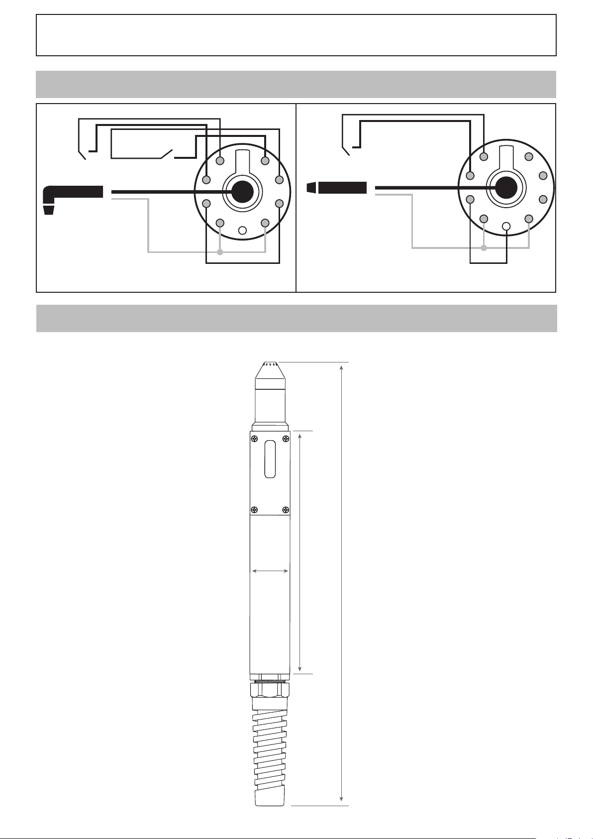
MT-125 / AT-125
9
8
7
6
5
4
3
2
1
trigger
safety
current cable
Central Adaptor
pilot
arc
+
-
CONNEXION / CONNECTION / VERBINDUNG / CONEXIÓN / ПОДКЛЮЧЕНИЕ / CONNECTIE /
CONNESSIONE
trigger
safety
current cable
-
+
pilot
arc
9
1
8
7
6
2
3
5
4
Central Adaptor
MT-125 AT-125
DIMENSIONS / DIMENSIONS / ABMESSUNGEN / DIMENSIONES / ДИМЕНЗИИ / DIMENSIONI /
AFMETINGEN
AT-125
safety
current cable
-
+
pilot
arc
Central Adaptor
9
8
7
5
6
1
2
3
4
310 mm
ø
35 mm
430 mm
37

38

39

JBDC SAS
1, rue de la Croix des Landes
CS 54159
53941 SAINT-BERTHEVIN Cedex
FRANCE
 Loading...