

Page 1
73502-V5-04/06/13
P : 10
-15 / 22-28
P : 4- 9/ 22-28
P : 16-28
www.gys.fr
Page 2
B
/
FIG-1
Gaine acier
⑬
⑬
⑬⑬
⑩
⑩
⑩⑩
⑫
⑫
⑫⑫
FIG-2
A/
FIG-3
MAGYS 350
MAGYS 350----4444
MAGYS 350MAGYS 350
MAGYS 450 W
MAGYS 450 WSSSS
MAGYS 450 WMAGYS 450 W
min
①①①①
MAGYS 350 GR
MAGYS 350 GR
MAGYS 350 GRMAGYS 350 GR
⑤
⑤
⑤⑤
⑦
⑦
⑦⑦
⑪
⑪
⑪⑪
⑨
⑨
⑨⑨
⑧
⑧
⑧⑧
Tube capillaire
Gaine téflon
③
③
③③
④
④
④④
x 2
②
②
②②
①
①
①①
⑥
⑥
⑥⑥
②②②②
④④④④
⑥⑥⑥⑥
2
⑧⑧⑧⑧
⑦⑦⑦⑦
③③③③
⑤⑤⑤⑤
⑧⑧⑧⑧
Page 3
3
FIG-4
P1
100 %
P4
⑨
⑨
⑨⑨
⑧
⑧
⑧⑧
⑩
⑩
⑩⑩
①
①
①①
⑦
⑦
⑦⑦
⑤
⑤
⑤⑤
FIG-5
⑪
⑪
⑪⑪
⑬⑬⑬⑬
②
②
②②
④
④
④④
⑥
⑥
⑥⑥
③
③
③③
P2 P3
P5
0 %
⑫
⑫
⑫⑫
50 % (*)
Page 4

4
DESCRIPTION
Merci de votre choix ! Afin de tirer le maximum de satisfaction de votre poste, veuillez lire avec attention ce qui suit :
Les Magys sont des postes de soudure semi-automatique « synergic » sur roues, ventilés pour le soudage (MIG ou
MAG). Ils fonctionnent sur une alimentation 400V triphasée. Pour fonctionner, le générateur Magys 450 WS doit être
utilisé avec le dévidoir séparé WS-4L (ref. 033573) et un faisceau de liaison. Pour fonctionner, le générateur Magys
350 GR doit être utilisé avec le dévidoir séparé AS-4R (réf. 034723) et un faisceau de liaison.
ALIMENTATION ÉLECTRIQUE
Le courant effectif absorbé (I1eff) pour les conditions d'utilisation maximales est indiqué sur l'appareil. Vérifier que
l'alimentation et ses protections (fusible et/ou disjoncteur) sont compatibles avec le courant nécessaire en utilisation.
L'appareil doit être placé de façon telle que la fiche de prise de courant soit accessible.
Ne pas utiliser de rallonge ayant une section inférieure à 4 mm². Ces appareils sont livrés avec une prise 32A de
type CEE 7/7. Ils doivent être reliés à une prise 400V 3Ph. AVEC terre protégée par un disjoncteur 25A min et un
différentiel 30mA.
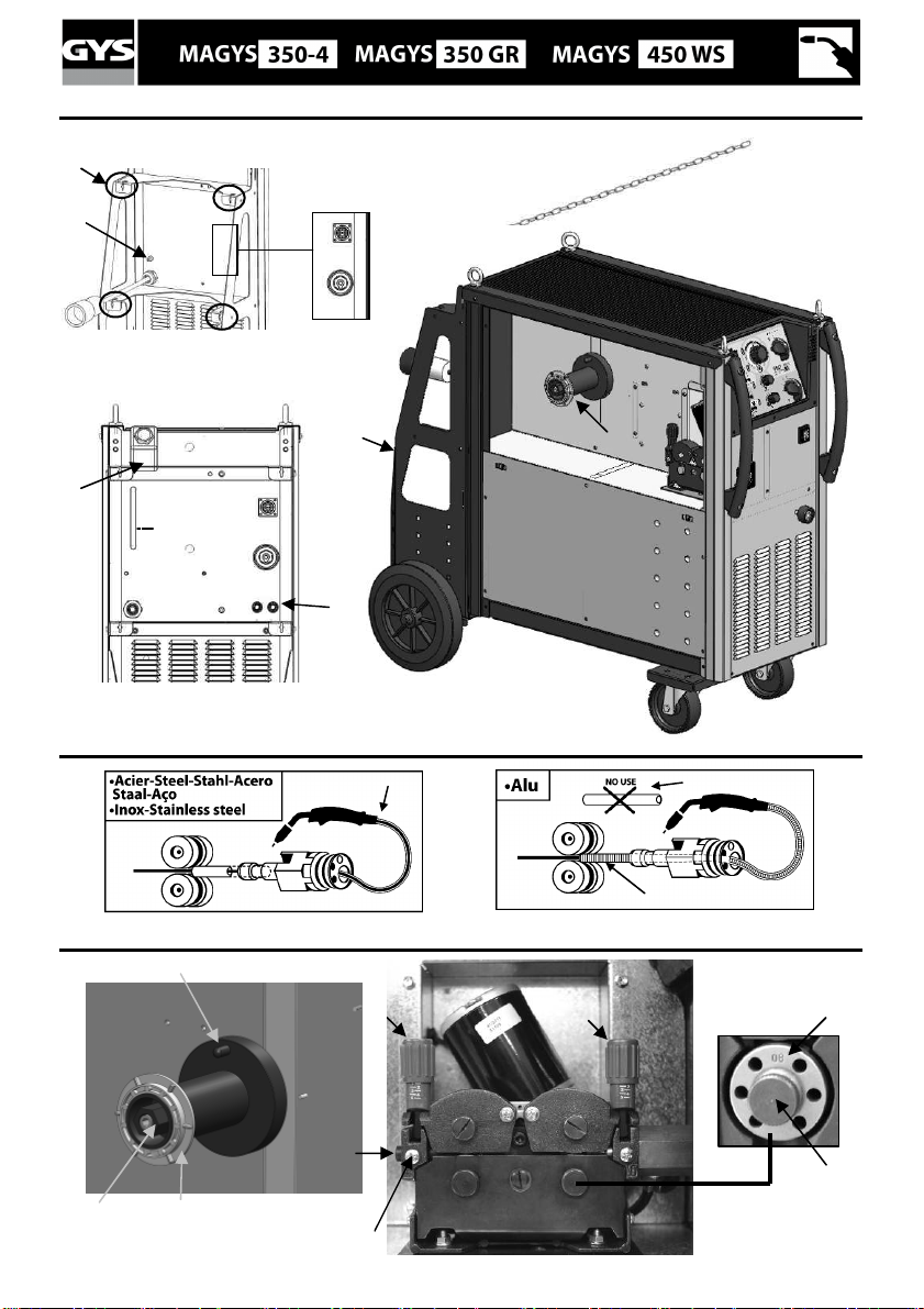
MONTAGE ET DESCRIPTION DU POSTE (Fig 1)
Mettre le tapis (uniquement pour le Magys 350-4) et les 4 anneaux de levage (avec leur rondelles). La bouteille de
gaz se fixe à l’aide de 2 chaînes à insérer dans les encoches prévues à cet effet. Attention : bien fixer la
bouteille. Il existe aussi des ouvertures pour passer des sangles (non fournies).
① Interrupteur marche – arrêt ⑧ Chaines de fixation pour bouteille.
② Deux commutateurs de réglage permettent d’ajuster
⑨ Support bobine Ø 200/300 mm.
la tension de soudage en sortie de générateur.
③ Clavier de réglage des paramètres de soudage. ⑩ Entrée gaz (Pour le Magys 450 WS, le tuyau gaz se
raccorde directement au manomètre de la bouteille).
④ Raccord torche au standard européen. ⑪ Panneau arrière de connexion pour dévidoir séparé
⑤ Câble d’alimentation (5m)
(Magys 350 GR / 450 WS)
⑥ Sortie pince de masse. ⑫ Réservoir 5,5 L (Magys 450 WS)
⑦ Support bouteille (maxi une bouteille de 10m3). ⑬ Encoche de fixation pour chaîne
SOUDAGE SEMI-AUTOMATIQUE EN ACIER / INOX (MODE MAG) (FIG-2-A)
Les MAGYS sont livrés d’origine pour fonctionner avec du fil Ø 1 mm en acier (galets réversible Ø 1/1,2 acier/inox).
S’assurer que l’ensemble galet, gaine, tube contact soit compatible avec le diamètre de fil utilisé.
L’utilisation en acier ou inox nécessite un gaz spécifique au soudage argon + CO2 (Ar + CO2) mais d’autres
combinaisons sont possibles. La proportion de CO2 varie selon l’utilisation. Pour le choix du gaz, demander conseil à
un distributeur de gaz. Le débit de gaz pour le soudage en acier se situe entre 15 et 25 L/min selon les conditions de
soudage.
SOUDAGE SEMI-AUTOMATIQUE ALUMINIUM (FIG-2-B)
Cet appareil peut souder du fil aluminium de 1 mm et plus.
Pour souder l’aluminium, il faut utiliser un gaz neutre: argon pur (Ar) mais d’autres combinaisons sont possibles.
Pour le choix du gaz, demander conseil à un distributeur de gaz. Le débit du gaz se situe entre 20 et 25 L/min selon
les conditions de soudage.
- Afin de ne pas écraser le fil, mettre un minimum sur les galets presseurs du moto-dévidoir.
- Retirer le tube capillaire avant de connecter la torche aluminium avec une gaine en téflon.
- Utiliser une torche spéciale aluminium qui possède une gaine téflon afin de réduire les frottements.
NE PAS couper la gaine au bord du raccord ! Cette gaine sert à guider le fil à partir des galets.
- Tube contact : utiliser un tube contact SPECIAL aluminium correspondant au diamètre du fil.
- Utiliser des galets spéciaux pour l’aluminium.
PROCÉDURE DE MONTAGE DES BOBINES ET DES TORCHES (FIG-3) :
• Positionner la bobine en tenant compte de l’ergot d’entrainement ① du support bobine. Pour monter une
bobine de 200mm, installer au préalable un adaptateur sur le support (ref. 042889).
• Régler le frein de la bobine ② pour éviter lors de l’arrêt de la soudure que l’inertie de la bobine n’emmêle le fil.
Serrer ensuite fermement l’écrou de maintien ③.
• Pour la première mise en service :
Page 5
5
desserrer la vis de fixation du guide fil ⑤
placer les galets, bien serrer leur vis de maintien ⑥
puis positionner le guide fil ⑦ au plus près du galet mais sans contact avec ce dernier, puis resserrer la
vis de fixation.
• Pour régler la molette des galets presseurs ⑧, bloquer le fil en sortie de torche, actionner le moteur. Le réglage
du serrage est bon lorsque les galets patinent sur le fil même si le fil est bloqué en bout de torche.
NOTA : Gâchette pressée, si le poste ne détecte pas de contact au bout de 4 secondes, il bascule sur le mode
« avance rapide » jusqu’au relâchement de la gâchette. Le gaz se coupe pendant cette opération.
ATTENTION : Pendant cette avance rapide, le fil est sous tension, il faut impérativement éviter tout contact
avec les pièces métalliques environnantes.
RACCORDEMENT GAZ
Visser le manodétendeur sur la bouteille de gaz si besoin est, puis connecter le tuyau fourni au raccord gaz (cf ⑩,
FIG-1 pour le MAGYS 350-4).
Pour éviter toute fuite de gaz, utiliser les colliers fournis dans la boîte d’accessoires.
REFROIDISSEMENT LIQUIDE (MAGYS 450 WS) (FIG-3) ET PROTECTION THERMIQUE
Connecter les raccords bleu et rouge du faisceau au générateur ⑪ et au dévidoir séparé (voir Notice du WS-4L)
Remplir le réservoir ⑫ jusqu’à son niveau maximum (5,5L de contenance). Le liquide de refroidissement
CORAGARD CS330 (ou équivalent), recommandé par GYS, doit impérativement être utilisé (plus d’information sur le
site : http://www.aqua-concept-gmbh.eu ). L’utilisation de liquides de refroidissement autres, et en particulier du
liquide standard automobile, peut conduire, par un phénomène d’électrolyse, à l’accumulation de dépôts solides dans
le circuit de refroidissement, dégradant ainsi le refroidissement, et pouvant aller jusqu’à l’obstruction du circuit.
Toute dégradation de la machine liée à l’utilisation d’un autre liquide de refroidissement que le CS330 préconisé (ou
équivalent) ne sera pas considérée dans le cadre de la garantie.
Le MAGYS 450 WS n’est pas préconisé pour fonctionner avec une torche refroidie air.
Si malgré tout une torche air devait être utilisée, un by-pass est livré avec le poste (en face arrière). Le
raccorder entre les raccords bleu et rouge. En cas de non respect de cette consigne, la pompe sera
endommagée, et cette panne ne sera pas prise en compte dans le cadre de la garantie.
Pour le MAGYS 450 WS NE JAMAIS UTILISER VOTRE POSTE SANS LIQUIDE DE REFROIDISSEMENT
lorsque la pompe est en fonctionnement. Respecter le niveau minimal (jauge face arrière)
En cas de non respect, vous risquez de détériorer de manière définitive la pompe du système de refroidissement.
• Respecter les règles classiques du soudage.
• Laisser les ouïes de l'appareil libres pour l’entrée et la sortie d’air.
• Laisser l’appareil branché quelques minutes après soudage pour permettre le refroidissement.
• Protection thermique : Le voyant ⑧ Fig-4 s’allume lorsque le poste se met en sécurité. La durée de
refroidissement (ventilation forcée) est par cycles de 10 minutes en fonction de la température ambiante pour le
350-4 et à 20 minutes (ventilation forcée + pompe) pour le MAGYS 350 GR/450 WS.
• Ventilation : La ventilation n’est active que lors du soudage et par cycles de refroidissement.
FACTEURS DE MARCHE & ENVIRONNEMENT D’UTILISATION
• Le poste décrit a une caractéristique de sortie de type "tension constante". Son facteur de marche selon la norme
EN60974-1 est indiqué dans le tableau suivant :
X / 60974-1 @ 40°C
Magys 350-4 / 350 GR 50% @ 350 A 320 A 260 A
(T cycle = 10 min)
Magys 450 WS 50% @ 450 A 410 A 320 A
I max
60% (T cycle = 10 min) 100% (T cycle = 10 min)
Note : les essais d’échauffement ont été effectués à température ambiante et le facteur de marche à 40 °C a été
déterminé par simulation.
• Ces appareils sont de Classe A. Ils sont conçus pour un emploi dans un environnement industriel ou
professionnel. Dans un environnement différent, il peut être difficile d’assurer la compatibilité électromagnétique,
à cause de perturbations conduites aussi bien que rayonnées. Ne pas utiliser dans un environnement comportant
des poussières métalliques conductrices.
Page 6
6
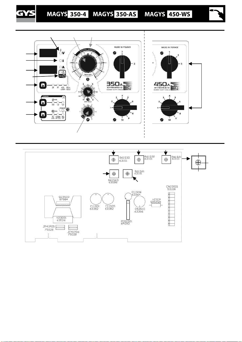
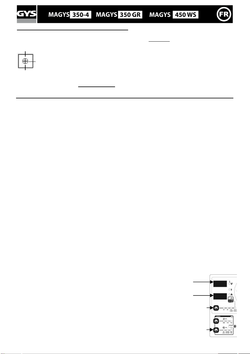
CLAVIER DE COMMANDE (FIG-4):
Choix du mode de soudage / test ①
2T : soudage 2 temps / 4T : soudage 4 temps.
SPOT : fonction bouchonnage / spot avec réglage du
diamètre du point.
Afficheur tension ⑨ : L’appui sur la gâchette (Le
voyant indique que la torche est sous tension)
affiche la valeur de la tension du réglage en cours.
Delay : Fonction « point de chainette »
2 modes sont proposés pour faciliter le réglage du
poste:« Manual » ou « Synergic ».
Fonction test : Le voyant s’allume Via l’appui sur la
Commutateurs ⑫ : 20 positions pour le Magys 350-4
et 350 GR et 30 pour le 450 WS.
touche ①. Voir description au chapitre « réglage du
poste »
Potentiomètre de réglage SPOT / DELAY③ : Fait
varier la durée du point, la taille du point et l’intervalle
entre chaque point.
Potentiomètre de la dynamique d’arc ④: Permet
d’ajuster en auto ou manuellement la dynamique d’arc.
Réglage de la vitesse fil ② : Potentiomètre
d’ajustage de la vitesse du fil. La vitesse varie de 1 à 22
m/minute.
Nota pour le MAGYS 350 GR et 450 WS : Il est possible
de sélectionner le potentiomètre du dévidoir déporté ou
du générateur.
Voir chapitre « sélection du potentiomètre de vitesse
Choix matière et mode Manuel ⑤ : Voir chapitre
fil » et l’autocollant à l’intérieur du dévidoir.
« réglage du poste »
Mode « Synergic » ⑥ : Voir chapitre « réglage du
poste »
Diamètre de fil ⑦: Sélection du diamètre de fil.
Afficheur intensité ⑩ : Affiche l’intensité (voyant
« A ») ou l’épaisseur ⑪ préconisée en fonction de la
puissance sélectionnée (voir fonction « test » au
chapitre « réglage du poste »).
Voyant de protection thermique ⑧: Voir chapitre
« conseils et protection thermique ».
REGLAGE DU POSTE : (FIG-4)
MODE « SYNERGIC »
Grâce à cette fonction, plus besoin de régler la vitesse fil.
Nota : L’information « NOP » indique que la tension
choisie est supérieure à celle préconisée pour la matière
sélectionnée et le diamètre de fil.
- Positionner le potentiomètre ② vitesse fil au milieu de la zone « Optimal synergic »
- Sélectionner : La nature du fil ⑤, le diamètre du fil ⑦, la tension de soudage (Par les 2 commutateurs
en face avant ⑫).
A partir de cette combinaison de paramètres, cet appareil détermine la vitesse de fil optimale et le poste est
prêt à souder. Il est ensuite possible d’ajuster la vitesse fil si nécessaire en + ou en – grâce au potentiomètre
②. Une mémorisation des dernières configurations de soudage est effectuée et réactivée à chaque mise en
route du poste (diamètre fil, nature fil, mode).
Fonction « test » : Uniquement en mode synergique, permet d’avoir une épaisseur indicative soudable en
fonction des paramètres sélectionnés sans consommer de gaz ni de fil. Ces valeurs sont calculées sur la base d’un
soudage en angle à plat. Attention : la torche est sous tension, éviter tout contact.
NOTA : Si le gaz, le diamètre de fil, le type de métal utilisés sont différents de ceux indiqués en mode synergique, il
faut alors passer par le mode manuel pour régler le poste.
MODE «MANUAL»
Pour régler votre poste procéder comme suit :
- En fonction de l’épaisseur à souder, choisissez la tension de soudage à l’aide des 2 commutateurs
- Ajustez la vitesse du fil à l’aide du potentiomètre ②.
Page 7
7
MODIFICATION DES PARAMETRES D’USINE (FIG-5) :
50 %
(Réglage
Fc1 s’affiche
In / Out s’affiche
L’appareil contrôle la vitesse d’accostage, le burn back et le post gaz. Ces paramètres sont réglés en usine, il est tout
de fois possible de les modifier directement sur la carte électronique. Attention : cette intervention doit être faite
par un électricien qualifié.
0 %
usine)
100 %
P1 : Réglage de la vitesse d’accostage permet une approche plus douce afin d’éviter les
éclaboussures aux premiers courts-circuits.
P2 : Réglage du Burn back. Cette fonction permet d’éviter au fil de venir se coller au tube
contact en fin de cordon.
P3 : Réglage du Post gaz. Réglage du temps pendant lequel le gaz continu de protéger le
bain de fusion à la fin du cordon.
P4-P5 : NE PAS TOUCHER
PARAMETRAGE DU MODE CACHE (FIG-4) :
Le mode caché permet d’atteindre les fonctions suivantes :
• le mode gougeage (Magys 350 GR et 450 WS)
• sélection du potentiomètre de vitesse fil (uniquement pour le Magys 350 GR et 450 WS)
• autorisation/interdiction des matériaux
L’accès à ce mode se fait par appui maintenu sur la touche 1 pendant 3 sec. L’afficheur indique « Fc0 » , « OFF ».
Appuyer de nouveau sur la touche 1 pour entrer dans le mode Gougeage.
Mode gougeage : (Magys 350 GR et 450 WS) (Fc0)
L’afficheur du haut indique « Arc », « Air » et l’afficheur du bas indique « OFF ».
Pour activer le générateur de courant, appuyer sur la touche 5. L’afficheur indique alors « Arc », « Air », « On ».
ATTENTION : une fois le générateur de courant activé, la puissance en sortie d’appareil est disponible. Ne pas poser
la torche au sol, en contact avec un matériau métallique, utiliser des équipements de protections, …
Pour désactiver le générateur de courant appuyer sur la touche 5. Pour sortir du mode gougeage, il faut appuyer sur
la touche 1. Cette sortie implique une sortie du mode caché, l’afficheur indique « END ».
Procédure du gougeage :
- Mettre le commutateur à pleine puissance,
- ouvrir le robinet d’air,
- le contact entre l’électrode et la pièce provoque un court-circuit. Un bain de fusion est immédiatement produit et
l’air canalisé par la torche projette le métal en fusion du bain.
- l’avance du travail se fait en poussant, à l’inverse du MMA.
Pour une utilisation optimale il faut toujours laisser 100 – 150 mm entre le bout de l’électrode et la pince de
gougeage.
La torche se connecte au générateur à l’arrière du produit, pôle + pour des électrodes acier, inox. Pour des
électrodes en cuivre se connecter à n’importe quel pôle. Pour une électrode Nickel se connecter au pôle -. La pince
de masse se branche de la même manière que pour le soudage.
Il est important de respecter les indications notées sur les boîtes d’électrodes utilisées.
Cette manipulation requiert un EPI obligatoire !
Sélection du potentiomètre de vitesse fil : (Magys 350 GR et 450 WS) (Fc1)
Le réglage de la vitesse fil peut se faire soit avec le potentiomètre du
dévidoir, soit avec celui du générateur. Les 2 ne peuvent pas être actifs en
même temps.
Pour entrer dans le mode « Sélection du potentiomètre de vitesse fil »
appuyer 3 sec sur la touche 1 et à nouveau sur cette touche. L’afficheur du
haut indique « Fc1 » et l’afficheur du bas indique:
- « Out » pour le potentiomètre du dévidoir
- « In » pour le potentiomètre du générateur
Pour passer de Out à In, il suffit d’appuyer sur la touche 5 dont les voyants
clignotent. En appuyant sur la touche 1 vous sortirez de cette fonction et
passerez à la fonction « Autorisation/Interdiction des matériaux »
Permet de sélectionner
le potentiomètre
①①①①
⑤⑤⑤⑤
3s
Page 8
8
Autorisation/interdiction des matériaux : (Fc2)
Il est possible d’autoriser ou non l’utilisation des 3 choix de matériaux (Fe CO², FeCrNi ArCO², Aluminium). Pour
entrer dans ce mode il suffit d’entrer dans le mode caché et d’appuyer 2 fois sur la touche 1. L’afficheur indique
« Fc2 ». Afin de choisir votre combinaison de matériaux (8 possibilités), il suffit d’appuyer sur la touche 5 jusqu’à
obtenir ce que vous souhaitez. La position « Manual » ne peut être désactivée.
Pour sortir du mode caché appuyer sur la touche 1, l’afficheur indique « END ».
ENTRETIEN
• L'entretien ne doit être effectué que par une personne qualifiée.
• Couper l'alimentation en débranchant la prise, et attendre l’arrêt du ventilateur avant de travailler sur
l'appareil. A l’intérieur, les tensions et intensités sont élevées et dangereuses.
• Deux à trois fois par an, enlever le flanc du poste et dépoussiérer à la soufflette. En profiter pour faire vérifier
la tenue des connexions électriques avec un outil isolé par un personnel qualifié.
• Contrôler régulièrement l'état du cordon d'alimentation. Si le câble d'alimentation est endommagé, il doit être
remplacé par le fabricant, son service après vente ou une personne de qualification similaire, afin d'éviter un
danger.
• Contrôler avant chaque utilisation l’état des câbles de soudage de la torche et de la pince de masse (il ne doit
pas y avoir de partie conductrice à nu).
• Etalonnage : Vérifier une fois par an la bonne calibration des outils d’affichage tension et courant de l’appareil.
Consulter le plan de maintenance de l’appareil.
SÉCURITÉ
Le soudage MIG/MAG peut être dangereux et causer des blessures graves voire mortelles. Protégezvous et protégez les autres. Respectez les instructions de sécurité suivantes
Déplacement du
poste :
Manutention avec
élingues (au pont):
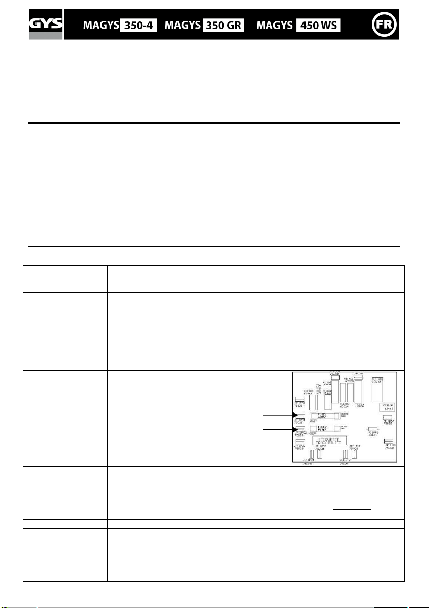
Fusibles (x2)
Débrancher la prise, vérifier que les chaines de maintien de la bouteille de gaz sont bien
en place, ne pas rouler sur les tuyaux ou câbles. Suivant la norme EN60974-1, ne pas
dépasser une inclinaison du poste de 15° lors du déplacement et de la mise en place.
- Enlever systématiquement la bouteille de gaz. Ne jamais manutentionner d’autres
charges avec le poste.
- Utiliser simultanément les 4 anneaux de levage en s’assurant que la charge soit bien
répartie et que l’angle entre les élingues et le poste soit d’au minimum 60°. Ne jamais
élinguer par les poignées.
- N’utiliser que les chaînes à maillons ou des élingues correctement dimensionnées et de
même largeur. Les crochets doivent être à verrouillage suivant la norme DIN 82101,
forme A, taille minimum 0,4. Le MAGYS 350-4S équipé pèse environ 160kg, le MAGYS 350
GR équipé pèse environ 210 kg et le MAGYS 450 WS environ 220kg.
Le circuit d’alimentation basse tension de
l’appareil est protégé par 2 fusibles (T2A)
situés sur la carte électronique interne du
générateur.
:
Rayonnements de
l’arc :
Pluie, vapeur d’eau,
humidité :
Choc électrique : Cet appareil ne doit être utilisé que sur une alimentation triphasée avec terre. Ne pas
Chutes : Ne pas faire transiter le poste au-dessus de personnes ou d’objets.
Brûlures : Porter des vêtements de travail en tissu ignifugés (coton, bleu ou jeans).
Risques de feu : Supprimer tous les produits inflammables de l'espace de travail. Ne pas travailler en
Vous protéger à l’aide d’un masque muni de filtres conformes EN 169 ou EN 379.
Utiliser votre poste dans une atmosphère propre (degré de pollution ≤ 3), à plat et à plus
d’un mètre de la pièce à souder. Ne pas utiliser sous la pluie ou la neige.
toucher les pièces sous tension. Vérifier que le réseau d'alimentation est adapté au poste.
Travailler avec des gants de protection et un tablier ignifugé.
Protéger les autres en installant des paravents ininflammables, ou les prévenir de ne pas
regarder l'arc et garder des distances suffisantes.
présence de gaz inflammable.
Page 9
9
Fumées : Ne pas inhaler les gaz et fumées de soudage. Utiliser dans un environnement
Précautions
supplémentaires :
correctement ventilé, avec extraction artificielle si soudage en intérieur.
Eviter toute opération de soudage :
- dans des lieux comportant des risques accrus de choc électrique,
- dans des lieux fermés,
- en présence de matériau inflammable ou comportant des risques d'explosion, doit
toujours être soumise à l'approbation préalable d'un "responsable expert", et effectuée en
présence de personnes formées pour intervenir en cas d'urgence. Les moyens techniques
de protections décrits dans la Spécification Technique CEI/IEC 62081 doivent être
appliqués. Le soudage en position surélevée est interdit, sauf en cas d'utilisation de
plates-formes de sécurité.
ANOMALIES, CAUSES, REMÈDES
SYMPTOMES CAUSES
Des grattons obstruent l’orifice.
Le débit du fil de soudage n’est pas
constant.
Le moteur de dévidage ne fonctionne
pas.
Mauvais dévidage du fil.
Pas de courant de soudage.
Le fil bouchonne après les galets.
Le cordon de soudage est poreux.
Le fil patine dans les galets.
Un des galets patine Vérifier le serrage de la vis du galet.
Frein de la bobine ou galet trop serré. Desserrer le frein et les galets
Problème d’alimentation
Gaine guide fil sale ou endommagée. Nettoyer ou remplacer.
Frein de la bobine trop serré.
Mauvais branchement de la prise
secteur.
Mauvaise connexion de masse.
Contacteur de puissance inopérant.
Gaine guide fil écrasée. Vérifier la gaine et corps de torche.
Blocage du fil dans la torche.
Pas de tube capillaire.
Vitesse du fil trop importante.
Le débit de gaz est insuffisant.
Bouteille de gaz vide.
Qualité du gaz non satisfaisante.
Circulation d’air ou influence du vent.
Buse gaz trop encrassée.
Mauvaise qualité du fil.
État de la surface à souder de
mauvaise qualité (rouille, etc…)
Le gaz n’est pas connecté
Particules d’étincelage
très importantes.
Pas de gaz en sortie de torche Mauvaise connexion du gaz
Tension d’arc trop basse ou trop
haute.
Mauvaise prise de masse.
Nettoyer le tube contact ou le changer
et remettre du produit anti-adhésion.
- Contrôler la pression des galets ou
les remplacer.
- Diamètre du fil non conforme au
galet.
-Gaine guide fil dans la torche non
conforme.
Vérifier que le bouton de mise en
service est sur la position marche.
Desserrer le frein.
Voir le branchement de la prise et
regarder si la prise est bien alimentée
avec 3 phases.
Contrôler le câble de masse
(connexion et état de la pince).
Contrôler la gâchette de la torche.
Remplacer ou nettoyer.
Vérifier la présence du tube capillaire.
Réduire la vitesse de fil
Plage de réglage de 15 à 25 L / min.
Nettoyer le métal de base.
La remplacer.
Le remplacer.
Empêcher les courants d’air, protéger
la zone de soudage.
Nettoyer la buse gaz ou la remplacer.
Utiliser un fil adapté au soudage MIGMAG.
Nettoyer la pièce avant de souder
Vérifier que le gaz est connecté à
l’entrée générateur.
Voir paramètres de soudage.
Contrôler et positionner la pince de
masse au plus proche de la zone à
souder
Vérifier le branchement des entrées de
gaz
Vérifier que l’électrovanne fonctionne
REMEDES
Page 10

DESCRIPTION
Thank you for choosing this GYS product; please read this instruction manual carefully before installing and
using the product, and keep in a safe place for future reference.
The MAGYS are ventilated semi-automatic welding units (MIG or MAG). Adjustment is quick and easy with their
« synergic wire speed » function. They work on a 400V three-phase power supply. The MAGYS 450 WS has to be
used with the separate wire feeder WS-4L (ref. 033573) and the appropriate contact batch. The MAGYS 350 GR
generator has to be used with the WS-4R wire feeder (ref. 034723) and a connection cable.
ELECTRICITY SUPPLY
The absorbed current (I1eff) is indicated on the device, for use at maximum settings. Check that the power supply
and its protection (fuse and/or circuit breaker) are compatible with the current needed during use.
The device must be placed in such way that the power socket is always accessible.
Do not use an extension cord which has a wire section smaller than 4 mm².
These units are supplied with a 32A plug type EEC7/7. They should be plugged in to a 400 V (3PH) power socket
WITH earth and protected by a circuit breaker (32A and 1 differential 30mA. )
DEVICE PRESENTATION
Put the rubber mat (only for the Magys 350-4) and the four ring eyes (with their lock washers). The gas bottle needs
to be fastened with 2 chains in the holes at the back of the machine. Attention: Fasten correctly the bottle. You
have also holes to pass a strap on (not included).
① On – Off switch ⑧ Fastening chains for bottles
② Power settings – 2 switches with 9 positions to
adjust the welding voltage output
③ Control panel – Welding settings ⑩ Gas connector (For the Magys 450 WS, the gas hose
④ European standard torch connection ⑪ Rear panel for the connection of the separate wire
⑤ Power cable (5m)
⑥ Earth cable ⑫5.5 L tank (Magys 450 WS)
⑦ Gas bottle support (max 1 bottle of 10m3) ⑬ Chain fixing slot
SEMI-AUTOMATIC WELDING FOR STEEL / STAINLESS STEEL (MAG MODE) (FIG. 2-A)
The MAGYS units are equipped originally to work on 1mm steel wire (original drive rollers Ø 1/1.2 steel/stainless
steel).
Make sure that drive rollers, liner and contact tube are adapted to your wire diameter.
For Steel or Stainless Steel, you will need to use specific gas - Argon + CO2 (Ar + CO2). The proportion of CO2 will
vary depending on usage. The gas flow for steel is between 15 and 25L / min depending on the environment and
experience of the welder.
SEMI-AUTOMATIC WELDING FOR ALUMINIUM (MIG MODE) (FIG. 2-B)
This welding unit can weld aluminium wires from 1mm.
To weld aluminium, neutral gas “pure Argon” (AR) is required. When choosing gas, ask a gas distributor for advice.
The gas flow in aluminium should be between 20 and 25 L / min depending on the environment and experience of
the welder.
Things to note when welding with Aluminium
- Set the pressure of the rollers to a minimum so as not to crush the wire
- Remove the capillary tube before connecting the aluminium torch
- When welding aluminium use a special aluminium torch with Teflon sheath to reduce friction.
Do not cut the sheath near the connector! It is used to guide the wire from the rollers. (See diagram ⑯)
- Contact Tip: Use the specific Aluminium contact tip corresponding to the diameter of the wire.
- Drive rollers: Use specific drive rollers to weld with aluminium wire.
REEL AND TORCH ASSEMBLY (FIG. 3)
• Position the reel on to the support
adapter (ref. 042889) on the support.
taking care of the pin
⑨ Reel support Ø 200/300 mm.
needs to be connected to the flowmeter of the bottle).
feeder (Magys 350 GR/450 WS)
. To place a 200mm wire reel, first install the
10
Page 11

• Adjust the reel break ② to avoid the reel movement tangling the wire when welding stops. Then tighten the
plastic screw ③ firmly.
• For the first use :
o Release the fixing screw of the wire guide ⑤
o Place the rollers, and tighten the screws .
o Place the wire guide ⑦ as close as possible to the roller but without touching it, then tighten the fixing
screw.
• To select the adjustment of the drive rollers ⑧, bend the wire where it comes out of the nozzle to stop it, and
then start the motor. Tighten the knob whilst pressing the trigger until the wire starts to move. The setting is
correct when the guide roller slides over the wire, even when it is blocked at the end of the torch.
NOTE: When the trigger is pulled and without any contact detected within 4s, the MAGYS will automatically switch
to the ‘fast forward’ mode until the trigger is released. There is no gas during this operation.
WARNING: The ‘fast forward’ mode use current in the wire; avoid any contact with any metallic part around.
GAS COUPLING
Fit the regulator/flowmeter to the gas bottle, and then fit the gas pipe to the connector (see , FIG-2 for MAGYS
350). To avoid gas leaks, use the collars provided in the accessories box.
LIQUID COOLING (MAGYS 450 WS) (FIG-2) & THERMAL PROTECTION
Connect the red and blue wire of the connecting harness from the generator ⑪ to the separate wire feeder (see
WS-4L user manual)
Fill the tank ⑫ up to its maximum (5,5L). The CORAGARD CS330 cooling liquid (or equivalent), recommended
by GYS, must be used (more information in the website: www.aqua-concept-gmbh.eu). The use of any other cooling
liquid, and especially the standard automobile liquid, can lead by electrolysis effect, to the accumulation of dumps in
the cooling system, damaging it and even more by blocking the circuit.
Any damage caused to the machine by the use of another cooling liquid will not be taken under warranty.
The MAGYS 450 WS is not recommended to be used by an air cooled torch.
If anyway you want to use an air cooled torch, a by-pass is supplied with the unit. Connect it between
the red and blue cables. If you don’t respect this rule, the pump will be damaged, and the repair will
not be taken under warranty.
MAGYS 450 WS: NEVER USE YOUR UNIT WITHOUT COOLING LIQUID
when the pump is working. Ensure liquid is at least minimum level (gauge at back of machine)
Failure to adhere to this may result in irreparable damage to the cooling system, and machine
• Always respect the basic rules of welding.
• Do not block/cover the ventilation holes of the machine.
• Leave the device plugged in after welding to allow proper cooling down.
• Thermal protection: The LED⑧ switches on when the unit is on safety mode. The cooling time (forced ventilation)
is by cycle of 10 minutes for the 350-4 and 20 minutes (forced ventilation + pump) for the MAGYS 350 GR/450 WS
depending on the external temperature.
• Ventilation: the fan is only active during the welding and the cooling cycles.
DUTY CYCLE & WELDING ENVIRONMENT IN USE
• The welding unit describes an output characteristic of "constant current" type. The duty cycles following the
standard EN60974-1 (at 40°C on a 10mn cycle) are indicated in the table below:
X / 60974-1 @ 40°C
MAGYS 350-4/350 GR 50% @350A 320A 260A
(T cycle = 10 min)
MAGYS 450 WS 50% @ 450A 410A 320A
I max
60% (T cycle = 10 min) 100% (T cycle = 10 min)
Note : The machines’ duty cycle has been tested at room temperature (40°C) and has been determined
by simulation.
These are Class-A devices. They are designed to be used in an industrial or professional environment. In a
different environment, it can be difficult to ensure electromagnetic compatibility, due to conducted disturbances
as well as radiation.
11
Page 12

CONTROL PANEL (FIG-4):
Welding mode selection / test ①
2T: two-stage welding / 4T: four-stage welding.
SPOT: Spot welding with adjustable spot diameter
Delay: intermittent welding modes for an optimised
operating procedure
2 modes to make easier the setting up of the welding
unit: « Manual » or « Synergic ».
Voltage display ⑨: By pulling the trigger (The
LED indicates that your torch is on) the voltage will
be displayed according to the parameters selected.
Power adjustment switch ⑫: 20 positions for the
Magys 350-4, 350 GR and 30 for the 450 WS.
Test function: The LED switches on when you push
the button①. Read chapter «Welding unit settings»
SPOT / DELAY potentiometer③: To adjust the
welding time of a point, the size of the point and the
time between each point.
Arc dynamics potentiometer ④: To adjust
automatically or manually the arc dynamics.
Metal selection and manual mode ⑤: Read chapter
«Welding unit settings»
Mode « Synergic » ⑥: Read chapter «Welding unit
settings»
Wire diameter : Select the wire diameter used.
Thermal protection LED ⑧: Read chapter «Thermal
protection».
Wire speed setting ②: Potentiometer to adjust the
wire speed. The speed can vary from 1 to 22 m/minute.
Note for the MAGYS 350 GR/450 WS: It is possible to
select either the potentiometer of the separate wire
feeder or the generator.
See chapter "wire speed potentiometer" and the sticker
inside the wire feeder.
Welding current display⑩: indicates the amperage
(LED « A ») or the thickness ⑪ recommended
according to the power selected (read « test » function
in the chapter « Welding unit settings »).
Note: « NOP » on the display indicates that the
welding current selected is superior to the one
recommended taking into account the parameters (type
and diameter of the wire).
WELDING UNIT SETINGS: (FIG-4)
« SYNERGIC » MODE
This function automatically controls the wire speed. There is no need to set the wire speed manually.
- Position the potentiometer ② in the middle of the « Optimal synergic » zone
- Select: Wire type ⑤, wire diameter ⑦, power mode (with the 2 power switches on the front ⑫).
From the settings chosen, the unit determines the optimum wire speed and is ready to weld. It is also
possible to manually adjust the wire speed (+ or –) if necessary using the potentiometer ②. The last welding
configuration is saved in the memory automatically (wire diameter, wire type, mode).
« Test » function : Only in the synergic mode, I twill indicate you the thickness you can weld with the
parameters selected without using any gas or wire. These values are calculated on the basis of a welding on
the flat surface. Attention: you have current in the torch, so avoid any contact with any metallic part.
NOTE: If the gas, the wire diameter, and the metal used are different from the ones selected in the synergic mode,
you will need to switch to the manual mode to set up the welding unit.
«MANUAL » MODE
To set your device, proceed as follows:
- Choose the welding voltage using the 2 power switches according to the thickness to weld.
- Adjust the wire speed using the potentiometer ②.
12
Page 13

MODIFICATION OF THE ORIGINAL PARAMETERS (FIG-4):
50 % (Factory
The device controls the arcing speed, the burn back and the post gaz. These parameters are set up in the factory,
but it is possible to modify them directly on the circuit board. Attention: this intervention must be done by a
qualified electrician.
0 %
setting)
100 %
P1: Set up the arcing speed to have a smooth start in order to avoid any spatter with the
first short circuit.
P2: Set up the Burn back to avoid the sticking of the wire on the contact tube.
P3: The setting up of the Post gas will regulate the time of gas used after the welding to
protect it.
P4-P5: DO NOT TOUCH
HIDDEN MODE PARAMETERS (FIG-4) :
The hidden mode allows you to set the following parameters:
- Gouging mode (only for Magys 350 GR and 450 WS)
- Selection of the wire speed potentiometer (only for Magys 350 GR and 450 WS)
- Metal Selection
To enter this mode, press and hold button 1 for 3 sec. The machine will display « Fc0 », « OFF ». Press button 1
again to enter Gouging mode.
Gouging mode: (only for Magys 350 GR and 450 WS) (Fc0)
The top screen will display « Arc », « Air » and the bottom screen « OFF ».
To activate the power generator, push button 5. The display will show « Arc », « Air », « On ».
ATTENTION: once the power generator is activated, the output current is available on the unit. Do not put the torch
on the floor or in contact with any metallic part. Always wear protective clothing.
To deactivate the power generator push button 5. To leave Gouging mode and hidden mode, push button 1 and the
screen will display « END ».
Gouging process:
- Turn the voltage switch to maximum,
- Open the cylinder valve or compressed air network,
- Contact between the electrode and the metal piece will create a circuit. The intense heat will melt the workpiece
and air will pass through the arc quickly enough to blow the molten material away.
- Conversely to the MMA process, the work is done by pushing the arc.
The visible length of the electrode must between 100 and 150 mm.
The torch is connected to the back of the generator, on the + terminal for steel and stainless steel electrodes. For
copper electrodes you can use any terminal. For Nickel electrodes connect the electrode holder to the – terminal.
The earth clamp is connected to the other terminal.
Always follow the instructions as indicated on the electrode packaging.
Protective clothing should always be worn when gouging!
Selection of the wire speed: (only for the Magys 350 GR/450 WS) (Fc1)
Wire speed can be adjusted using wire feeder potentiometer or generator
potentiometer. Only one potentiometer can be active at a time.
Fc1 is displayed
On this type of equipment with separate wire feeder, 2 wire speed
potentiometers are available. You can choose to use between both but they
can’t be activated at the same time.
In / Out is
displayed
To enter into « Selection of the wire speed potentiometer » mode push button
1 for 3 seconds and then press the same button again. The top screen will
display « Fc1 » and the bottom one:
- « Out » for the separate wire feeder potentiometer
- « In » for the generator potentiometer.
To choose between Out and In, press button 5. Press button 1 to leave this
Potentiometer
selection
mode and enter another mode.
①①①①
⑤⑤⑤⑤
3s
13
Page 14

Metal selection (Fc2)
This mode will allow you to select or de-select a specified combination of 3 types of metal (Fe CO², FeCrNi ArCO²,
Aluminium). To enter this mode, follow the instruction to enter hidden mode and press button 1 twice. The screen
will display « Fc2 ». In order to choose the combination of metal (8 selections available), press button 5 until you
reach the combination required. The « Manual » position can’t be deactivated.
To leave the hidden mode press button 1, the screen will display« END ».
MAINTENANCE
• Maintenance should only be carried out by a qualified person.
• Ensure the machine is unplugged, and that the ventilator inside has stopped before carrying out maintenance
work. (DANGER High Voltage and Currents).
• It is recommended removing the steel cover 2 or 3 times a year to remove any excess dust. Take this
opportunity to have the electrical connections checked by a qualified person with an insulated tool.
• Regularly check the condition of the power supply cord. If damaged, it will need to be replaced by the
manufacturer, its after sales service or a qualified person.
• Before each use, check the state of welding cables of the torch and earth clamp (The conductive metal should
not be exposed).
• Calibration: Check once a year the good calibration of the tools calculating welding current and voltage.
Consult the maintenance plan of the welding unit.
SAFETY
Arc welding can be dangerous and can cause serious and even fatal injuries.
Protect yourself and others. Ensure the following safety precautions are taken:
Handling Unplug the unit, check if the chains of the gas bottle are fastened enough, don’t ride over
Lifting - Systematically remove the gas bottle. Do not lift the unit with any other charge.
Fuses (x2)
the wires and cables. In compliance with the EN60974-1 standard, don’t tilt the unit more
than 15° when you move or set up the welding unit.
- Use simultaneously the four ring eyes being sure that the weight is well distributed and
the angle between the strap and the machine is at a minimum of 60°. Do not lift the
welding unit with the handles.
- Use only the link chains or straps with the correct size and the same width. The hooks
need to be locked in compliance with the standard DIN 82101, shape A, minimum size
0.4. The weight with equipment of the MAGYS 350-4S is around 160kg, the MAGYS 350
GR equipped weighs around 210 kg and around 220kg for the MAGYS 450 WS.
The low voltage circuit of the unit is
protected by 2 fuses (T2A) located on the
circuit board of the generator.
Arc radiation: Protect yourself with a helmet fitted with filters in compliance with EN169 or EN 379
Rain, steam, damp Use your welding unit in a clean/dry environment (pollution factor ≤ 3), on a flat surface,
and more than one meter from the welding work-piece. Do not use in rain or snow.
Electrical shock: This device must only be used with an earthed power supply. Do not touch the parts
under high voltage. Check that the power supply is suitable for this unit
Falls: Do not place/carry the unit over people or objects.
Burns: Wear protective (fire-proof) clothing (cotton, overalls or jeans).
Wear protective gloves and a fire-proof apron.
Ensure other people keep a safe distance from the work area and do not look directly at
the welding arc. Protect others by installing fire-proof protection walls.
Fire risks: Remove all flammable products from the work area. Do not work in presence of
flammable gases
Fumes: Do not inhale welding gases and fumes. Use the device in a well ventilated environment,
with artificial extraction if welding indoors.
14
Page 15

Additional
precautions:
Avoid any welding operation undertaken in:
- rooms where there is an increased risk of electric shocks,
- Poorly ventilated rooms,
- In the presence of flammable or explosive material,
Use should always be approved by a "responsible expert", and made in presence of
people trained to intervene in case of emergency.
Technical protection as described in the Technical Specification CEI/IEC 62081 must be
implemented. Welding in raised positions should not be undertaken, except in case of
safety platforms use.
People wearing Pacemakers are advised to see their doctor before using this device.
Do not use the welding unit to unfreeze pipes.
Handle gas bottles with care - there is increased danger if the bottle or its valve are damaged.
TROUBLESHOOTING
SYMPTOMS POSSIBLE CAUSES REMEDIES
Debris is blocking up the opening.
The welding wire speed is not
constant.
The wire-feeder motor doesn’t
operate.
Bad wire feed.
No welding current
The wire jams (after the rollers)
The welding bead is porous
The arc produces a lot of sparks
No gas flow at the end of the torch. Bad gas connection.
The wire skids in the rollers.
The rollers slide over the wire
Reel or roller brake too tight. Adjust the brake and rollers.
Electrical supply problem.
Covering wire guide dirty or damaged. Clean or replace
Reel brake too tight
Bad connection to the main supply.
Bad earth connection.
Torch trigger inoperative.
Guide wire sheath crushed. Check the sheath and torch body.
Wire jammed in the torch
No capillary tube.
Wire speed too fast
The gas flow rate is not sufficient.
Gas bottle empty.
Gas quality unsatisfactory.
Air flow or wind influence.
Gas nozzle dirty.
Poor quality wire.
Work-piece in bad condition. (rust,
etc…)
Arc voltage too low or too high. See welding settings.
Bad earth connection.
Insufficient gas flow.
Clean out the contact tip or change it
and replace the anti-adherence
product.
Ref.041806
- Check the roller pressure or replace
it.
- Wire diameter incompatible with
roller
- Covering wire guide in the torch
incompatible.
Check and tighten the roller’s screws.
Check that the power switch is in the
"On" position.
Adjust the brake
Check the mains connection and
ensure the supply is 400 V (3PH).
Check the earth cable (connection and
clamp condition).
Check the torch trigger / replace torch
Clean or replace.
Check the presence of capillary tube.
Reduce the wire speed
Adjust flow range 15 to 25 L / min.
Clean the work-piece.
Replace
Replace
Prevent drafts, protect welding area.
Clean or replace the gas nozzle.
Use suitable WIRE for MIG-MAG
welding.
Clean the metal before welding.
Check the earth cable (connection and
clamp condition)
Adjus the gas flow.
Check that the gas pipe is plugged
properly.
Check the solenoid valve.
15
Page 16

BESCHREIBUNG
Wir freuen uns, dass Sie sich für unser Gerät entschieden haben und danken Ihnen für das entgegengebrachte
Vertrauen. Um das Gerät optimal nutzen zu können, lesen Sie bitte die Betriebsanleitung sorgfältig durch.
Die Magys sind fahrbare halb-synergische und aktivgekühlte Schutzgasschweißgeräte, die sich für das MIG oder MAG
Schweißen eignen. Sie werden mit einem 400V (dreiphasigen) Netzanschluss betrieben. Die Magys 450 WS muss mit
dem separaten Drahtvorschubkoffer WS-4L (wassergekühlt - Art.-Nr. 033573) und einem Zwischenschlauchpaket
ausgerüstet werden. Die Magys 350 GR muss mit dem separaten Drahtvorschubkoffer WS-4R (luftgekühlt - Art.-Nr.
034723) und einem Zwischenschlauchpaket ausgerüstet werden.
NETZANSCHLUSS
Für den Einsatz des Gerätes bei Maximaleinstellungen, ist der aufgenommene Strom (I1eff) am Gerät aufgedruckt.
Überprüfen Sie, ob die Stromversorgung und die Schutzeinrichtungen (Sicherungen und/oder Schutzschalter) mit
dem Strom, den Sie beim Schweißen benötigen, übereinstimmen.
Achten Sie beim Aufstellen des Gerätes darauf, dass der Netzstecker immer frei zugänglich ist. Benutzen Sie kein
Verlängerungskabel, dessen Querschnitt kleiner als 4mm² ist. Die MAGYS werden mit einem 32A Netzstecker (Typ
RS-015 CEE 400V) geliefert und müssen an eine dreiphasige 400V Steckdose + Erde (abgesichert durch 32A Kurve D
oder Sicherung 30A Typ mA) angeschlossen werden.
BESCHREIBUNG
Legen Sie die Gummimatte (nur für die Magys 350-4) auf das Gerät und schrauben die 4 Kranösen (mit den
dazugehörigen Unterlegscheiben) fest. Die Gasflasche wird mit zwei Ketten befestigt, die in die dafür vorgesehenen
Befestigungsmöglichkeiten (Schlitze) eingehängt werden. Achtung : bitte befestigen Sie die Flasche gut.
Desweiteren befinden sich rechts und links an der Flaschenbefestigung Öffnungen, die ein weiteres Verzurren mittels
Spanngurten (nicht im Lieferumfang enthalten) ermöglicht.
① Ein/Aus Schalter ⑧ Befestigungsketten für Gasflaschen.
② Zwei Schweißspannungsregler zur Anpassung der
Schweißleistung.
③ Bedienfeld zur Einstellung der Schweißparameter. ⑩ Schutzgasanschluss (bei der Magys 450 WS wird der
④ Eurozentralanschluss ⑪ Hinterer Steckeranschluss für ein separates
⑤ Netzstromkabel (5m)
⑥ Ausgang Masseklemme ⑫ Kühlmitteltank 5,5 L (Magys 450 WS)
⑦ Auflageplatte für Gasflasche (max. 1 Flasche von 50 L).
SYNERGISCHES STAHL-/ EDELSTAHL- SCHWEISSEN (MAG MODUS) (S. ABB. 2-A)
Das Gerät ist für den Betrieb mit Ø 1mm Stahldraht werksseitig voreingestellt (Drahtrolle Ø 1/1.2mm). Bei Draht Ø
⑨ Aufnahmedorn für Drahtrolle Ø 200 oder 300 mm.
Gasschlauch unmittelbar an den Manometer der
Gasflasche angeschlossen).
Drahtvorschubgerät (Magys 350 GR/450 WS)
⑬
Nut für Befestigungskette
1mm, ist ein Brenner mit einem Ø 1mm Kontaktrohr erforderlich. Stahl- und Edelstahl-Schweißungen können die
Verwendung spezifischer Mischgase z.B. Argon + CO2 (Ar + CO2) erfordern. Der Mengenanteil des CO2 variiert je
nach Einsatzzweck. Fragen Sie den Gasfachhandel nach dem optimalen Gas bei außergewöhlichen Anwendungen.
Die Gasdurchflussmenge bei Stahlschweißarbeiten beträgt in der Regel 15 bis 25 L/min je nach
Umgebungsverhältnissen.
SYNERGISCHES ALUMINIUM - SCHWEISSEN (MIG MODUS) (S. ABB. 2-B)
Mit diesem Gerät können 1 mm und 1,2 mm Aluminiumdrähte verschweißt werden.
Um Aluminium zu schweißen, ist das neutrale Gas “Rein-Argon” (AR) zu empfehlen. Fragen Sie den Gasfachhandel
nach dem optimalen Gas bei außergewöhnlichen Anwendungen. Die Gasdurchflussmenge bei
Aluminiumschweißarbeiten beträgt in der Regel 20 bis 25 L/min je nach Umgebungsverhältnissen.
- Der weiche Aluminiumdraht sollte mit möglichst geringem Anpressdruck zwischen den Drahtförderrollen
transportiert werden, da er andernfalls deformiert und ungleichmäßig gefördert wird.
- Kapillarrohr: Bei dem Einsatz eines speziellen Aluminiumbrenners sollte das im Zentralanschluss steckende Rohr
entfernt werden.
- Verwenden Sie einen speziellen Brenner für Aluminium. Dieser Brenner verfügt über eine Kunststoffführungsseele,
die die Reibung während der Drahtförderung im Schlauchpaket reduziert.
Schneiden Sie die Kunsstoffseele unter keinen Umständen direkt am Zentralanschluss ab! Die Seele
dient dazu den Draht unmittelbar von den Rollen zu übernehmen (siehe Abbildung ⑯).
- Benutzen Sie ein Kontaktrohr SPEZIELL für Alu, das dem gewählten Drahtdurchmesser entspricht.
- Benutzen Sie spezielle Drahtführungsrollen für Aluminium
16
Page 17

MONTAGE DER DRAHTROLLEN UND SCHWEISSBRENNER (S. ABB. 3)
• Positionieren Sie die Drahtrolle auf dem Aufnahmedorn ③ des Haspelträgers. Um eine 200mm Drahtrolle
zu verwenden, müssen Sie zuerst einen Adaptater (Art.-Nr. 042889) am Haspelträger anbringen.
• Justieren Sie die Drahtrollenbremse ②, um die Drahtrolle bei Schweißstopp gegen Nachdrehen zu sichern. Ziehen
Sie die Halterungsschraube ③ fest.
• Drahtransport-Montage:
o Lockern Sie die Fixierungsschrauben ⑤ der Drahtführung.
o Legen Sie die Drahtransportrollen mit der passenden Nut ein und ziehen Sie die Halterungsschraube ⑥ fest.
o Positionieren Sie die Drahtführung ⑦ so nah wie möglich an der Transportrolle. Dir Drahtführung darf keinen
Kontakt mit der Transportrolle haben. Ziehen Sie nun die Fixierungsschrauben wieder an.
• Um den Transportdruck ⑥ korrekt einzustellen, betätigen Sie bei eingelegtem Draht den Brennertaster und
justieren die Andruckmutter so, dass der Draht konstant transportiert wird. Zu starker Andruck wirkt sich
negativ aus. Legen Sie zur Kontrolle den aus dem Kontaktrohr austretenden Draht zwischen Daumen und
Zeigefinger und lösen Sie den Brennertaster aus. Wird der Draht bei leichtem Fingerdruck noch konstant
gefördert, ist der Antrieb korrekt eingestellt. Die übliche Andruckeinstellung des Drahttransports ⑥ befinden
Sie bei 3-4 für Stahl und 2-3 für Aluminium.
HINWEIS: Wenn das Gerät beim Drücken des Brennertasters nach 4 Sekunden keinen Kontakt ermittelt, wechselt
es in den Modus „erhöhte Drahtvorschubgeschwindigkeit“ bis Sie den Brennertaster loslassen. Während dieser
Phase strömt kein Gas aus.
ACHTUNG: Während der Modus „erhöhte Drahtvorschubgeschwindigkeit“ » aktiv ist, steht der Draht unter
Spannung. Deshalb ist es zwingend erforderlich, dass der Kontakt mit anderen metallischen
Gegenständen vermieden wird.
GAS-ANSCHLUSS
Montieren Sie einen Druckminderer an die Gasflasche wenn erforderlich und schließen Sie den im Lieferumfang
enthaltenen Schlauch an den Gasanschluss an (siehe ⑩, Abb-2 für die MAGYS 350).
Um Gasverlust zu vermeiden, verwenden Sie die in der Zubehörbox enthaltenen Schlauchklemmen.
WASSERKÜHLUNG (MAGYS 450 WS) (ABB-2) UND THERMISCHER SCHUTZ
Schließen Sie die blauen und roten Anschlüsse an die Stromquelle ⑪ und an den separaten Drahtvorschubkoffer an
(siehe Betriebsanleitung des WS-4L)
Füllen Sie den Tank ⑫ auf bis zu dem maximalen Füllstand (5,5L Inhalt). Das von GYS empfohlene
Kühlmittel CORAGARD CS330 (oder ähnliches) muss verwendet werden (für mehr Information, besuchen Sie die
Webseite: http://www.aqua-concept-gmbh.eu). Die Verwendung anderer Kühlflüssigkeiten, insbesondere von
Standardkühlflüssigkeiten, kann wegen der Elektrolyseprozesse zur Bildung von festen Substanzen innerhalb des
Kühlkreislaufes führen, die der Effizienz der Kühlung schaden und unter Umständen zum Totalausfall des Systems
durch Verstopfen führen können. Schäden, die durch das Verwenden nicht autorisierter Kühlflüssigkeiten wie CS330
(oder ähnliches) an der Maschine entstehen, werden nicht von der Garantie abgedeckt.
Die MAGYS 450 WS ist nicht für den Betrieb mit einem luftgekühlten Brenner entworfen.
Falls Sie trotzdem einen luftgekühlten Brenner benutzen möchten, wird ein « by-pass » mit dem Gerät
geliefert. Schließen Sie den zwischen den blauen und roten Anschlüssen an. Bei Nichtbeachtung dieser
Regel beschädigen Sie die Pumpe des Kühlsystems. Dieser Schaden wird im Rahmen der Garantie nicht
berücksichtigt.
(MAGYS 450 WS) DIE ANLAGE DARF BEI EINGESCHALTETER PUMPE NICHT OHNE KÜHLMITTEL
BENUTZT WERDEN! Beachten Sie die Mindestfüllmenge (Füllanzeige auf der Rückseite)
• Beachten Sie bitte die Grundregeln des Schweißens
• Verschließen Sie nicht die Lüftungsöffnungen des Gerätes, um eine Luftzirkulation zu ermöglichen.
• Lassen Sie das Gerät nach Beendigung der Arbeit noch eine Zeit eingeschaltet, um die Abkühlung zu ermöglichen.
• Thermischer Schutz: die Kontrollampe ⑧ leuchtet auf wenn das Gerät in den Schutzmodus geht. Die Dauer der Kühlung
(erzwungene Kühlung) besteht aus 10 Minuten Zyklen, abhängig von der Umgebungstemperatur bei der MAGYS 350-4 und
aus 20 Minuten Zyklen (erzwungene Kühlung + Pumpe) bei der MAGYS 350 GR/450 WS.
• Kühlung: die Kühlung ist nur während des Schweißens aktiv und funktioniert durch Kühlungszyklen.
Bei Nichtbeachtung beschädigen Sie die Pumpe des Kühlsystems und die Schweißbrenner.
17
Page 18

EINSCHALTDAUER – UMGEBUNGSBEDINGUNGEN
• Das Gerät arbeitet mit einer „Konstantstrom-Kennlinie“. Die Angaben für die Einschaltdauer folgen der Norm
EN60974-1 und werden in nachfolgender Tabelle angezeigt:
X / 60974-1 @ 40°C (T Zyklus = 10 min) I max 60% (T Zyklus = 10
MAGYS 350-4/350 GR 50% @ 350A 320A 260A
MAGYS 450 WS 50% @ 450A 410A 320A
min)
100% (T Zyklus = 10 min)
Bemerkung: Der Überhitzungstest wurde bei Raumtemperatur durchgeführt und die Einschaltdauer bei
40°C durch Simulation ermittelt.
• Diese Geräte gehören der Klasse A an. Sie wurden entwickelt für eine Anwendung im industriellen und/oder im
professionellen Bereich. Sollte das Gerät in einer anderen Umgebung betrieben werden, kann es eventuellen
Beeinträchtigungen durch elektromagnetische Felder kommen. Verwenden Sie das Gerät nicht in Räumen, in
denen sich in der Luft metallische Staubpartikel befinden, die Elektrizität leiten können.
BEDIENEINHEIT (FIG-4):
Auswahl des Schweißmodus / Test ①
2T : 2-Takt Schweißen / 4T : 4-Takt Schweißen.
SPOT : Heftschweißfunktion – mit einstellbaren
Parametern
DELAY : Funktion „Schweißpause“
Zwei Modi ermöglichen die Einstellung des Gerätes auf
„Manuell“ oder „Synergic“.
Testfunktion: Die LED leuchten auf, wenn Sie diese
Spannungsanzeige ⑨: Beim Betätigen des Brennertasters
(die Anzeige bedeutet, dass der Brenner unter
Spannung steht) wird der Wert der zurzeit angewählten
Spannung angezeigt.
Stufenschalter ⑫ : 20 Stufen für die Magys 350-4, 350
GR und 30 Stufen für die 450 WS.
Option ① wählen. Für weitere Informationen lesen Sie
bitte das Kapitel „Einstellung der Anlage“.
Drehregler SPOT / DELAY③: Hier wird die Schweißzeit,
die Größe des Punktes, sowie der Intervall zwischen jedem
Punkt eingestellt.
Drehregler „Lichtbogendynamik“ ④: Einstellbarkeit der
Lichtbogendynamik „manuell“ oder „synergisch“.
Materialauswahl und manueller Modus ⑤: Für weitere
Informationen lesen Sie bitte das Kapitel „Einstellung der
Anlage“.
„Synergic“ Modus ⑥ : Siehe Kapitel „Einstellung der
Anlage“
Drahtdurchmesser ⑦: Auswahl des Drahtdurchmessers.
Überhitzungsschutz ⑧: Siehe Kapitel „Hinweise und
thermischer Schutz“.
GERÄTEEINSTELLUNG (FIG4):
« SYNERGIC » MODUS :
In dieser Funktion muss die Drahtvorschubgeschwindigkeit nicht separat eingestellt werden.
- Stellen Sie das Potentiometer auf die Zone „Optimal Synergic“.
- Wählen Sie aus den Drahttyp , Drahtdurchmesser 7 und die Leistung (mittels der 2 Stufenschalter an der
Einstellung der Drahtgeschwindigkeit ② :
Potentiometer zur Einstellung der Drahtgeschwindigkeit. Die
Einstellbarkeit der Geschwindigkeit variiert zwischen 1 bis 22
m/Minute.
Hinweis für die MAGYS 350 GR/450 WS: Zur Einstellung
kann sowohl der Drehregler am externen
Drahtvorschubkoffer, als auch der Regler am Generator
selbst verwendet werden.
Siehe Kapitel "Auswahl des Potentiometers für die
Drahtgeschwindigkeit" und der Aufkleber auf der Innenseite
des Gehäuses des Drahtvorschubkoffers.
Intensitätsanzeige ⑩: Zeigt die Intensität (Anzeige „A“)
oder die empfohlene Dicke ⑪ an, je nach der ausgewählten
Schweißleistung (s. „Test“ Funktion im Kapitel „Einstellung
des Gerätes“).
Hinweis : Hinweis : Die Anzeige « NOP » auf dem Display
weist darauf hin, dass die eingestellte Schweißspannung in
Bezug auf die gewählten Einstellungen des
Drahtdurchmessers und des Materials zu hoch ist.
Frontseite ⑫)
Anhand dieser Parameter stellt das Gerät automatisch die optimale Drahtvorschubgeschwindigkeit schweißbereit
ein. Eine Feinregulierung erfolgt hier im „Optimal Synergic“- Bereich des Drahtvorschubreglers . Für die jeweiligen
Brenner wird die letzte Einstellung für Drahtdurchmesser, Drahttyp und Modus gespeichert.
„Test“ Funktion : nur im Synergic Modus - ermittelt die ungefähre Materialstärke die geschweißt werden kann, ohne Gas
oder Schweißdraht zu verbrauchen. Diese Werte werden auf der Basis einer Schweißung mit flachem Winkel berechnet.
Achtung : der Brenner steht unter Spannung, vermeiden Sie jeglichen Kontakt.
HINWEIS : Falls das Gas, das Drahtdurchmesser und der benutzte Metalltyp anders sind als die, die im „Synergic“ Modus
angezeigt werden, müssen Sie die Schweißparameter über den „Manuell“ Modus einstellen.
18
Page 19

«MANUELL» MODUS
50 %
3Sek.
angezeigt
Geräteeinstellung:
- Schweißpannung über 2 Stufenschalter entsprechend der Blechdicke wählen.
- Drahtvorschubgeschwindigkeit mittels Potentiometer anpassen.
ÄNDERUNG DER WERKSPARAMETER (ABB-4) :
Das Gerät kontrolliert die Drahtgeschwindigkeit, den Drahtrückbrand und die Gas-Nachströmung. Diese Parameter werden im
Werk eingestellt, Sie können diese aber direkt auf der Platine ändern. Achtung : diese Änderung muss durch einen
qualifizierten Elektriker vorgenommen werden.
0 %
100 %
(Werkseinstellung)
DIE EINSTELLMÖGLICHKEITEN IM VERSTECKTEN MODUS (FIG4):
P1 : Stellen sie die Lichtbogenfrequenz ein um das Zündverhalten zu verbessern und
Schweißspritzer zu vermeiden.
P2 : Einstellung des Drahtrückbrands um ein Festbrennen des Drahts am Kontaktrohr des
Brenners zu vermeiden.
P3 : Einstellung der Gas-Nachströmung. Einstellung der Dauer während deren das Gas das
Schmelzbad am Ende der Schweißnaht weiter schützt.
Der versteckte Modus ermöglicht dem Benutzer die folgenden Einstellmöglichkeiten vorzunehmen:
• Funktion zum Fugenhobeln(nur bei der Magys 350 GR/450 WS)
• Auswahl des Potentiometers zur Einstellung der Drahtvorschubgeschwindigkeit
• Wahl des Metalls
Um in diesen Modus zu gelangen, halten Sie die Taste 1 drei Sekunden lang gedrückt. Auf dem Display des Geräts
erscheint „Fc0“, „OFF“. Drücken sie erneut die Taste 1 um in den Fugenhobelmodus zu gelangen.
Der Fugenhobelmodus: (nur bei der Magys 350 GR/450 WS einstellbar) (Fc0)
Das obere Display zeigt „Arc“ und „Air“ an, das untere „Off“.
Um den Generator einzuschalten, drücken Sie bitte die Taste 5. Das Display zeigt in diesem Fall „Arc“, „Air“ , „On“.
ACHTUNG: Ist der Generator eingeschaltet, so liegt an diesem Strom an. Bitte achten Sie darauf, dass der Brenner nicht in
Berührung mit dem Boden oder einem metallischen Gegenstand kommt. Tragen Sie immer Schutzkleidung. Um den Generator
abzuschalten, drücken Sie erneut die Taste 5. Um aus dem Fugenhobeln und dem „versteckten“ Modus zu gelangen, drücken
Sie die Taste 1. Das Display zeigt in diesem Fall „END“ an.
Gehen Sie wie folgt vor:
Drehen Sie den Schalter zur Spannungsregulierung auf maximum.
Schließen Sie das Gerät an eine Druckluft-Leitung an, und stellen Sie sicher, dass das Druckventil am Gerät selbst offen ist.
Durch die Berührung des Werkstücks mit der Elektrode entsteht ein Kurzschluss. Die dadurch entstehende Hitze lässt das
Werkstück schmelzen, und die durch den Lichbogen geführte Druckluft bläst das geschmolzene Material aus.
Im Gegensatz zum E-Handschweissen wird hier der Lichtbogen „gedrückt“.
Die sichtbare Länge der Elektrode muss zwischen 100 und 150mm liegen.
Der Brenner wird auf der Rückseite des Generators, an den Pluspol für Stahl-/ Edelstahl-Elektroden angeschlossen. Für
Nickel-Elektroden schließen Sie bitte den Elektrodenhalter an den Negativpol des Generators an. Kupferelektroden können
sowohl am Plus- als auch am Negativpol angeschlossen werden. Die Masseklemme wird jeweils an den anderen (freien) Pol
angeschlossen.
Leisten Sie immer den Anweisungen auf der jeweiligen Verpackung folge.
Tragen Sie immer Schutzkleidung wenn sie Fugenhobeln.
Auswahl der Drahtgeschwindigkeit: (nur für die Magys 350 GR/450 WS) (Fc1)
Die Einstellung der Drahtgeschwindigkeit kann entweder mit dem Potentiometer am
Drahtvorschubkoffer oder an der Stromquelle erfolgen. Beide Potis können nicht
gleichzeitig aktiv sein.
Bei diesem Gerätetyp, mit separatem Drahtvorschub, stehen zwei Potentiometer zur
Wahl mit denen die Vorschubgeschwindigkeit reguliert werden kann. Es kann jedoch
immer nur ein Potentiometer aktiv sein.
Um in das Menü „Auswahl des Drahtvorschubpotentiometers“ zu gelangen, halten
Sie bitte die Taste 1 drei Sekunden lang gedrückt, und drücken Sie danach diese
Taste noch einmal. Das obere Display zeigt nun „Fc1“ an, und
• „Out“ für den Regler des separaten Drahtvorschubs
• „In“ für den Regler des Generators
Um zwischen „In“ und „Out“ wechseln zu können, drücken Sie die Taste 5. Mit einem
Druck auf die Taste 1 verlassen Sie den Modus und gelangen zur Auswahl zurück.
das Untere:
Fc1 wird angezeigt
IN / Out wird
①①①①
Dient zur Auswahl
des Potentiometers
⑤⑤⑤⑤
19
Page 20

Metall Auswahl (Fc2):
Dieser Modus erlaubt Ihnen die Wahl/Abwahl der Kombination von drei Metalltypen (Fe CO², FeCrNi ArCO², Aluminium). Um
in diesen Modus zu gelangen, folgen Sie den Anweisungen zum „versteckten Modus“ und drücken Sie die Taste 1 zweimal.
Die Anzeige auf dem Display zeigt nun „Fc2“. Anstelle der Auswahl der Kombinationen (8 Auswahlmöglichkeiten), drücken Sie
Taste 5 bis Sie die erforderliche Kombination erreicht haben. Die Position „Manual“ kann nicht deaktiviert werden!
Um den „versteckten Modus“ zu verlassen, drücken Sie die Taste 1. Auf dem Display erscheint nun „END“.
INSTANDHALTUNG
• Die Instandhaltung sollte nur von qualifiziertem Fachpersonal durchgeführt werden
• Trennen Sie die Stromversorgung des Gerätes und warten Sie bis der Ventilator sich nicht mehr dreht. Im Gerät
sind die Spannungen sehr hoch und deshalb gefährlich.
• Nehmen Sie regelmäßig das Gehäuse ab und reinigen Sie das Innere des Gerätes mit Pressluft. Lassen Sie
regelmäßig Prüfungen des GYS Gerätes auf seine elektrische Betriebssicherheit von qualifiziertem Fachpersonal
durchführen.
• Prüfen Sie regelmäßig den Zustand der Netzzuleitung. Wenn diese beschädigt ist, muss sie durch den Hersteller,
seinen Reparaturservice oder eine qualifizierte Person ausgetauscht werden, um Gefahren zu vermeiden.
• Vor jeder Anwendung, prüfen Sie den Zustand der Schweisskäbel des Brenners und der Masseklemme (Die
Isolierung der Kabel muss im einwanfreien Zustand sein).
• Kalibrierung : Prüfen Sie einmal im Jahr die richtige Kalibrierung der Spannungs- und Stromanzeigen des Gerätes.
Nehmen Sie hierfür den Wartungsplan des Gerätes zur Hilfe.
UNFALLPRÄVENTION
Lichtbogenschweissen kann gefährlich sein und zu schweren – unter Umständen auch tödlichen – Verletzungen führen.
Schützen Sie daher sich selbst und andere. Beachten Sie unbedingt die folgenden.
Bewegung des
Geräts :
Anheben des Geräts:
Sicherungen (x2)
Trennen Sie das Gerät vom Stromnetz und stellen Sie sicher, dass die Flaschenhalterung (Kette)
gespannt ist und die Flasche nicht verrutschen kann. Fahren Sie nicht über Kabel oder Drähte! Bitte
neigen Sie die Maschine nicht mehr als 15° während Sie die Maschine bewegen oder Aufbauen (in
Übereinstimmung mit der Norm: EN60974-1).
¤ Bitte entfernen Sie die Gasflasche! Heben Sie das Gerät nicht an ohne die Gasflasche entfernt
zu haben!
¤ Nutzen Sie zum Anheben alle Kranösen um eine gleichmäßige Gewichtsverteilung zu gewährleisten.
Der Winkel zwischen den Seilen und der Maschine sollte mindestens 60° betragen. Heben Sie das
Gerät nicht mit den Handgriffen an!
¤ Nehmen Sie nur Ketten/Seile mit derselben Länge und der gleichen, ausreichend dimensionierten
Lastgrenze. Die Haken müssen der Norm DIN 82101 entsprechen und darüber hinaus noch den
folgenden Anforderungen entsprechen: Form A, Mindestgröße 0,4. Das Gewicht der Geräte liegt bei
160kg für die Magys 350-4S, 210kg für die MAGYS 350 GR und 220kg für die Magys 450 WS (Angabe
jeweils inkl. Zubehör).
Der Niederspannungsbereich der
Platine des Geräts ist mit zwei
Sicherungen (T2A) abgesichert. Diese
finden Sie auf der Platine des
Generators.
Lichtbogenstrahlung
Feuchtigkeit
Stromversorgung
Transport
Verbrennungsgefahr
Brandgefahr
Gesichtshaut und Augen sind durch ausreichend dimensionierte EN 175 konforme Schutzschirme mit
Spezialschutzgläsern nach EN 169 / 379 vor der intensiven Ultraviolettstrahlung zu schützen
Nicht bei erhöhter Feuchtigkeit (Regen/Schnee) benutzen.
Das Gerät darf nur an einer dafür geeigneten Stromversorgung betrieben werden. Keine
Spannungsführenden Teile berühren. Verwenden Sie niemals einen beschädigten Brenner, da dies zu
Schäden an der Maschine sowie an der Elektrik verursachen kann
Bewegen Sie das Gerät nicht über Personen oder Sachen hinweg und lassen Sie es nicht herunterfallen
oder hart aufsetzen
Schützen Sie sich durch geeignete trockene Schweißerkleidung (Schürze, Handschuhe, Kopfbedeckung
sowie feste Schuhe).
Tragen Sie auch eine Schutzbrille, wenn Sie Schlacke abklopfen. Schützen Sie andere durch nicht
entzündbare Trennwände.
Nicht in den Lichtbogen schauen und ausreichend Distanz halten
Entfernen Sie alle entflammbaren Produkte vom Schweissplatz und arbeiten Sie nicht in der Nähe von
brennbaren Stoffen und Gasen
20
Page 21

Schweissrauch
Weitere Hinweise
FEHLER, URSACHEN, LÖSUNGEN
Die beim Schweißen entstehenden Gase und der Rauch sind gesundheitsschädlich. Der Arbeitsplatz sollte
daher gut belüftet sein und der entstehende Rauch und die Gase müssen abgesaugt werden
Führen Sie Schweißarbeiten:
- in Bereichen mit erhöhten elektrischen Risiken,
- in abgeschlossenen Räumen,
- in der Umgebung von entflammbaren oder explosiven Produkten,
nur in Anwesenheit von qualifiziertem Rettungs- und/oder Fachpersonal durch. Treffen Sie
Vorsichtsmaßnahmen in Übereinstimmung mit „IEC 62081“. Schweißarbeiten an Gegenständen in
größeren Höhen dürfen nur auf professionell aufgebauten Gerüsten durchgeführt werden
FEHLERSUCHE URSACHE LÖSUNG
Das Kontaktrohr ist verstopft. Reinigen Sie das Kontaktrohr oder tauschen Sie
Der Draht rutscht im Antrieb durch. Prüfen Sie den Druck des Rollenantriebes oder
Drahtvorschubgeschwindigkeit nicht
konstant.
Eine der Antriebsrollen schiebt sich über
den Draht.
Motor läuft nicht. Bremse der Drahtrolle oder Rollenantrieb
Schlechte Drahtförderung. Drahtführungsseele verschmutzt oder
Kein Schweißstrom.
Drahtstau im Antrieb. Seele fehlerhaft. Prüfen bzw. austauschen.
Die Schweißnaht ist porös.
Starke Spritzerbildung.
Gasmangel am Brenner. Keine Verbindung zum Gas.
zu fest.
Versorgungsproblem. Prüfen Sie, ob der Schalter auf Position «EIN»
beschädigt.
Drahtrollen-Bremse zu fest. Lockern Sie die Bremse.
Fehlerhafte Netzversorgung. Prüfen der Netzversorgung (Stecker, Kabel,
Fehlerhafte Masseverbindung. Prüfen Sie die Masseklemme (Verbindung und
Brenner defekt. Prüfen Sie den Brenner bzw. tauschen Sie
Draht blockiert im Brenner. Prüfen, reinigen oder austauschen.
Fehlendes Kapillarrohr. Prüfen und einsetzen.
Drahtvorschubgeschwindigkeit zu hoch. Drahtvorschubgeschwindigkeit reduzieren.
Gasfluß zu niedrig.
Gasflasche leer. Austauschen.
Schlechte Gasqualität. Austauschen.
Zugluft. Schweißzone abschirmen.
Schmutzige Gasdüse. Reinigen oder austauschen.
Schlechte Drahtqualität.
Schweißmaterial von schlechter Qualität
(Rost, …)
Gas nicht angeschlossen Überprüfen Sie, ob das Gas am Eingang der
Lichtbogenspannung zu niedrig oder zu
hoch.
Masse schlecht positioniert. Positionieren Sie die Masse näher an der
Schutzgasfluss zu gering. Prüfen und Einstellen.
es aus und benutzen Sie Antihaftspray (Art.-Nr.
041806).
ändern die Antriebsnut auf die korrekte
Drahtstärke.
-Drahtführungsschlauch des Brenners nicht
korrekt.
Überprüfen Sie die Fixierschrauben der
Antriebsrollen.
Lockern Sie die Bremse und den Rollenantrieb.
ist.
Reinigen Sie die Drahtführungsseele oder
tauschen Sie diese aus.
Steckdose, Sicherung) und vergewissern Sie
sich, dass der Netzstecker an einer dreiphasigen
Stromversorgung angeschlossen ist.
Klemmenzustand).
diesen aus.
Korrigieren Sie die Gaseinstellung.
Reinigen Sie das Material.
Austauschen gegen geeigneten Schweißdraht.
Schweißgut reinigen.
Stromquelle angeschlossen ist.
Schweißparameter kontrollieren.
Schweißstelle.
Überprüfen Sie, ob der Gasschlauch mit dem
richtigen Geräteanschluss verbunden ist.
Überprüfen Sie, ob der Elektroventil
funktioniert.
21
Page 22

CONDITIONS DE GARANTIE FRANCE
• La garantie n’est valable que si le bon a été correctement rempli par le vendeur.
• La garantie couvre tout défaut ou vice de fabrication pendant 2 ans, à compter de la date d’achat (pièces et main
d’œuvre).
• La garantie ne couvre pas les erreurs de tension, incidents dus à un mauvais usage, chute, démontage ou toute autre
avarie due au transport.
• La garantie ne couvre pas l’usure normale des pièces (Ex. : câbles, pinces, etc.).
En cas de panne, retournez l’appareil à la société GYS (port dû refusé), en y joignant :
• Le présent certificat de garantie validé par le vendeur
• Une note explicative de la panne.
Après la garantie, notre SAV assure les réparations après acceptation d’un devis.
Contact SAV :
Société Gys-134 Bd des Loges
BP 4159-53941 Saint-Berthevin Cedex
Fax: +33 (0)2 43 01 23 75 - Tél: +33 (0)2 43 01 23 68
HERSTELLERGARANTIE
Die Garantieleistung des Herstellers erfolgt ausschließlich bei Fabrikations- oder Materialfehlern, die binnen 24 Monate nach
Kauf angezeigt werden (Nachweis Kaufbeleg). Nach Anerkenntnis des Garantieanspruchs durch den Hersteller bzw. seines
Beauftragten erfolgen eine für den Käufer kostenlose Reparatur und ein kostenloser Ersatz von Ersatzteilen. Der
Garantiezeitraum bleibt aufgrund erfolgter Garantieleistungen unverändert.
Ausschluss:
Die Garantieleistung erfolgt nicht bei Defekten, die durch unsachgemäßen Gebrauch, Sturz oder harte Stöße sowie durch nicht
autorisierte Reparaturen oder durch Transportschäden, die infolge des Einsendens zur Reparatur, hervorgerufen worden sind.
Keine Garantie wird für Verschleißteile (z. B. Kabel, Klemmen, Vorsatzscheiben etc.) sowie bei Gebrauchsspuren
übernommen.
Das betreffende Gerät bitte immer mit Kaufbeleg und kurzer Fehlerbeschreibung ausschließlich über den Fachhandel
einschicken. Die Reparatur erfolgt erst nach Erhalt einer schriftlichen Akzeptanz (Unterschrift) des zuvor vorgelegten
Kostenvoranschlags durch den Besteller. Im Fall einer Garantieleistung trägt GYS ausschließlich die Kosten für den
Rückversand an den Fachhändler.
Déclaration de conformité :
Gys atteste que les postes de soudure MAGYS sont fabriqués conformément aux exigences des directives
Basse tension 2006/95/CE du 12/12/2006, et aux directives CEM 2004/108/CE du 15/12/2004.
Cette conformité est établie par le respect des normes harmonisées EN60974-1 de 2005, EN 50445 de
2008, EN 60974-10 de 2007.
Le marquage CE a été apposé en 2012.
Declaration of conformity :
The equipment described on this manual is conform to the instructions of low voltage 2006/95/CE of
12/12/2006, and the instructions of CEM 2004/108/CE of the 15/12/2004.
This conformity respects the standards EN60974-1 of 2005, EN 50445 de 2008, EN60974-10 of 2007.
CE marking was added in 2012.
Konformitätserklärung
GYS erklärt, dass die synergisch geregelten Schweißanlagen MAGYS richtlinienkonform mit folgenden
europäischen Bestimmungen hergestellt wurden: Niederspannungsrichtlinie 2006/95/CE –12.12.2006 und
EMV- Richtlinien 2004/108/CE – 15.12.2004 elektromagnetische Verträglichkeit- hergestellt wurden. Diese
Geräte stimmen mit den harmonisierten Normen EN60974-1 von 2005, EN 50445 von 2008, EN60974-10
von 2007 überein.
CE Kennzeichnung: 2012.
29/02/2012 Nicolas BOUYGUES
Société GYS Président Directeur Général
134 BD des Loges
53941 Saint-Berthevin
France
22
Page 23

MAGYS
450 WS
MAGYS 350
-4
③
⑤
⑥
②
⑧
⑨⑨⑨⑨
⑬
⑬
⑭
⑭ ⑮
⑯
⑯
⑰
⑰
⑱
⑩
⑩
⑫
⑮
⑳⑳⑳⑳
MA
GYS 350 GR
PIÈCES DE RECHANGE / SPARE PARTS / ERSATZTEILE
④
⑪⑪⑪⑪
①
23
31
31 32
3131
②
25
⑦
⑥
25
24
⑲⑲⑲⑲
21
22
22
2222
⑳
⑳
⑳⑳
⑱
33
35
28
29
24
⑲
⑲
⑲⑲
22
22
2222
34
30
⑫
34
27
23
Page 24

Charnière / Hinge / Scharnier
- 71751
- 71772
- 717585T
- 71334
- 55147
N°
1
2
3
4
5
6
7
8
9
10
11
12
13
14
15
16
17
18
19
20
21
22
23a
23b
24
25
26
27
Connecteur ¼ faisceau de liaison (95²) / Contact batch connector (1/4 - 95²) /
28
Zwischenschlauchpaketbuchse (1/4 – 95²)
29 Connecteur eau / Water connector / Anschluss für Kühlflüssigkeit
30 Radiateur / Cooler / Kühler
31 Pompe / Pump / Pumpe
32 Réservoir / Tank / Tank
33 Bouchon de reservoir / Tank cap / Tankdeckel
34 Raccord coudé eau / Water elbow connector / Winkelanschluss für Kühlflüssigkeit
35 Faisceau de liaison interne / Internal contact batch / Inner Zwischenschlauchpaket
Désignation 350 350 GR 450 WS
Poignée / Handle / Griff
Bouton réglage de vitesse fil Ø 40/ Wire speed adjusting knob Ø 40/ Poti
Drahtvorschubgeschwindigkeit Ø 40
Bouton SPOT/ SPOT button / SPOT Poti
Bouton dynamic d’arc
Clavier de commande/ Control Keyboard / Bedienfeld
Interrupteur I/O/ I/O Switch / EIN/ AUS Schalter
Commutateur 2 positions / 2 positions switch / 2-stufiger Spannungsschalter
Commutateur 3 positions / 3 positions switch / 3-stufiger Spannungsschalter
Commutateur 10 positions / 10 positions switch / 10-stufiger Spannungsschalter
Motodévidoire (sans galet) / Wire feeder (without roller) / Drahtvorschub (ohne
Drahtförderrollen)
Câble d'alimentation (5m) / Supply cable (5m) / Netzstromkabel (5m)
Support bobine 15Kg / Reel support 15 Kg / Drahtförderrollen 15Kg
Roue avant / Front wheels / Vorderrad
Pont de diodes / Diode bridge / Gleichrichter
Self / Induction oil / Drossel
Transformateur de puissance / Transformer/ Transformator
Ventilateur / Fan / Ventilator
Roue diamètre 250mm / 250mm diameter wheels / Hinterrad 250mm Durchmesser
Embout d'axe / End axis / Endachse
Contacteur 24V AC 32A / Contactor 24V AC 32A / 24V AC 32A Schalter
Transformateur de commande / Control transformer / Steuertransformator
Electrovanne / Solenoid valve / Gasventil
Carte CEM / EMC board / EMV Karte
Carte d'affichage / Display card / Anzeigekarte
Carte micro controleur / µcontroller board / µControllerkarte
Connecteur 1/4 cable de masse (50²) / Earth cable connector (1/4) (50²) / (-)
Texasbuchse (1/4 - 50²)
Fusible carte (T2A) / Board fuse (T2A) / Kartesicherung T2A
Ecrou cage M6 / M6 cage nut / M6 Käffigmutter
72005 - -
56014
73080 – 73081 - 73082
73083 – 73085 - 73103
51932
51934
52461
51055
-
51060
51110
51065
51064
21470
71603
71367
52176
96058
96056
52175
96059
96057
51003
71376
71384
51107
51101
96060
71512
97208C
97163C
97161C
97165C 97248C
97162C
51461 -
51367
41169
350 GR 450 WS
51461 51478
- 71437
94895ST
-
24
Page 25

SCHÉMA ÉLECTRIQUE / CIRCUIT DIAGRAM / SCHALTPLAN
MAGYS 350-4
25
Page 26

MAGYS 350 GR
26
Page 27

MAGYS 450 WS
27
Page 28

ICONES / SYMBOLS / ZEICHENERKLÄRUNG
X
I2
…
U2
…
A Ampères Amps Ampere
V Volt Volt Volt
Hz Hertz Hertz Hertz
Soudage MIG/MAG (MIG : Metal Inert Gas / MAG : Metal Active Gas) MIG/MAG Welding (MIG :
Metal Inert Gas / MAG : Metal Active Gas) MIG/MAG Schweißen (MIG: Metal Inert Gas/ MAG: Metal
Active Gas)
Convient au soudage dans un environnement avec risque accru de choc électrique. La source de
courant elle-même ne doit toutefois pas être placée dans de tels locaux. Adapted for welding in
environment with increased risks of electrical shock. However, the welding source must not be placed in
such places. Geeignet für Schweißarbeiten im Bereich mit erhöhten elektrischen Risiken. Trotzdem
sollte die Schweißquelle nicht unbedingt in solchen Bereichen betrieben werden.
IP23
Protégé contre l’accès aux parties dangereuses des corps solides de diam >12,5mm et chute d'eau
(30% horizontal) Protected against access to dangerous parts by any solid body which is Ø >
12,5mm and against rain-fall (30% horizontal) Gegen Eindringen von Körpern mit einem
Durchmesser> 12,5mm und gegen Sprühwasser geschützt (Einfallwinkel 30% horizontal)
Courant de soudage continu Welding direct current Gleichschweißstrom
Alimentation électrique triphasée 50Hz ou 60Hz Three-phase power supply 50 Hz or 60Hz
Dreiphasige Netzversorgung mit 50 Hz order 60 Hz
Alimentation électrique triphasée 50Hz Three-phase power supply 50 Hz Dreiphasige
Netzversorgung mit 50 Hz
Uo Tension assignée à vide Rated no-load voltage Leerlaufspannung
U1 Tension assignée d’alimentation rated supply voltage Netzspannung
I1max
Courant d’alimentation assigné maximal (valeur efficace) Rated maximum supply current
(effective value) Maximaler Versorgungsstrom (Effektivwert)
I1eff Courant d’alimentation effectif maximal Maximum effective supply current Maximaler
tatsächlicher Versorgungsstrom
EN60 974-1 L’appareil respecte la norme EN60974-1 The device complies with EN60974-1 standard relative to
welding units Das Gerät entspricht der Norm EN60974-1 für Schweißgeräte
Transformateur-redresseur triphasée Three-phase converter-rectifier Dreiphasiger
Trafo/Frequenzumwandler
(40°C)
Facteur de marche selon la norme EN 60974-1 (10 minutes – 40°C) Duty cycle according to the
standar EN 60974-1 (10 minutes – 40°C) Einschaltdauer gemäß EN 60974-1 (10 Minuten – 40°C)
I2 : courant de soudage conventionnnel correspondant I2 : corresponding conventional welding
%
current I2 : entsprechender Schweißstrom
U2 : Tensions conventionnelles en charges correspondantes U2 : conventional voltages in
%
corresponding load U2 : entsprechende Arbeitsspannung
Appareil conforme aux directives européennes The device complies with European Directive
Gerät entspricht europäischen Richtlinien
中国安全质量标准证明
Conforme aux normes GOST (Russie) Conform to standards GOST / PCT (Russia)
in Übereinstimmung mit der Norm GOST/PCT
L’arc électrique produit des rayons dangereux pour les yeux et la peau (protégez-vous !) The
electric arc produces dangerous rays for eyes and skin (protect yourself !) Der elektrische Lichtbogen
verursacht Strahlungen auf Augen und Haut (Schützen Sie sich !)
Attention, souder peut déclencher un feu ou une explosion. Caution, welding can produce fire or
explosion. Achtung! Schweißen kann Feuer oder Explosion verursachen
Attention ! Lire le manuel d’instruction avant utilisation Caution ! Read the user manual
Achtung! Lesen Sie die Betriebsanleitung
Produit faisant l'objet d'une collecte sélective- Ne pas jeter dans une poubelle domestique
Separate collection required – Do not throw in a domestic dustbin Für die Entsorgung Ihres Gerätes
gelten besondere Bestimmungen (Sondermüll). Es darf nicht mit dem Hausmüll entsorgt werden
28
 Loading...