

Page 1

1
MIG 3
INSTRUCTION MANUAL
FOR SEMI-AUTOMATICAL
WELDING MACHINES
MAGYS 410
GENEGYS 510 SF
GENEGYS 515 WSF
II / NORM CE
This product has been designed with respect of the European standards.
- Directive Low Voltage 73/23 CEE of 19th February 1973 (decree n°98- 1081 of 3rd October 1995)
- Directive electromagnetic compatibility 89/336 CEE of 3rd May 1989
This conformity is established in compliance with EN60974-1 and A1/A2 of 2003 (Low voltage Directive) and EN
50199 (Electromagnetic compatibility Directive)
73326
GYS
Mise à jour
: 07/11/06
Réf 73326
Page 2

2
Thank you for choosing our product! Before installing and using the product, please read carefully the following
recommendations of safety in order to avoid accidents to the user and damages of the welding process.
GYS can’t be responsible for the damages occurred to persons or things, which derive from the use of the machine
in following circumstances:
- Modification or neutralization of safety elements,
- Non respect of the recommendations written in the manual instruction,
- Modification of the characteristics on the product
- Use of the accessories, which are different from the ones delivered by GYS,
- Non-respect of the regulating and particular dispositions where the machine is settled.
I/ SAFETY STANDARDS AND GENERAL PRECAUTIONS
GENERALITIES
1- Before disassembling the product’s body, plug out the lead cable.
2- The operators must have the appropriate qualification.
3- The operations of servicing can only be controlled by qualified technicians.
4- The operator is responsible for respect of the car manufacturers’ recommendations, concerning the
protection of electrical and electronic procedures (car computer, car radio, alarm, air bag, etc…)
5- It is necessary to make a regular preventive maintenance.
ELECTRICITY
1- Check that the unity must be connected to the earth coupler and that the connection to the earth is in good
condition.
2- Check that the workbench is connected to the earth coupler.
3- Make sure that the operator has no contact with the metal parts to the welded without any protection or wet
clothes.
4- Avoid being in contact with welding part.
5- Before controlling or repairing, please disconnect the unit directly to the level of the plug.
PROTECTION OF EYES AND BODY
1-During the welding process, the operator must be protected from the eventual flashes of the electrical arc
with protection clothes like leather gloves, welding aprons, safety shoes, welding helmets or glasses for filtering
radiations and projections. As well during operations of rubbing and hammering, the operator must protect his eyes.
2-All the protection board must be in good condition and maintained in place.
Never look at an arc of welding without any protection of your eyes.
Protect the environment near the product against projections and reflections.
SMOKES AND GAZ
Welding operations can cause the emission of toxic smokes and harmful metallic dusts. Use the device in a sheltered
place equipped with smoke aspirators.
The operator must wear an anti smoke mask.
The welding material must be degreased and cleaned in order to limit the toxic gas during the welding process.
FIRE
1-Check that the sparks don’t cause fire especially near inflammable material.
2-Check that fire extinguishers are not too far from the operator.
3-Leave the product in a place with air movers.
4-Don’t weld neither on container of combustibles and lubricants, even empty, nor on containers with
infla mmable material.
5-Don’t weld in an atmosphere full with inflammable gas or fuel steam.
ELECTRO-MAGNETIC COMPATIBILITY
Near the spot-welding, check:
- There is neither no other power supply cable nor control lines, nor phone cables, nor radio or TV reception
appliances, nor watches, nor mobile phones, nor magnetic cards, nor computers or any other electronic
appliance.
- There are in the surroundings (minimum 3 meters of each point of the product) no persons using active medical
appliances (pacemakers, acoustic prosthetics).
Make supplementary protections if other products are used in the same environment.
Page 3
3
II / CONNECTIONS OF POWER SUPPLY CABLES
Electricity:
Three phases 400V 50Hz. Use of the PHASE 1, PHASE 2, PHASE3 and EARTH CONNECTION on a three phases
plug (Don’t use NEUTRAL).
Protection of the line:
MAGYS 410: Circuit breaker 25A curve D or fuse 25A type aM
GENEGYS 510 SF and GENEGYS 515 WSF: Circuit breaker 32A curve D or fuse 32A type aM
III/ DESCRIPTION OF THE MACHINE
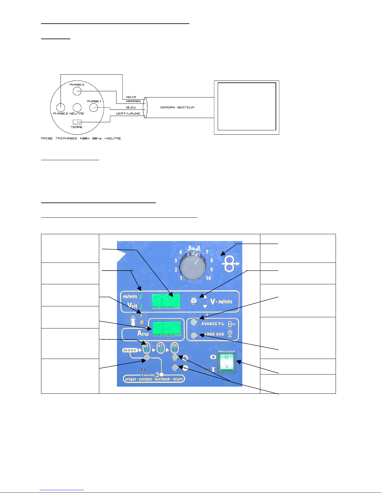
MAGYS 410 and GENEGYS 510 SF: Foreside (Higher part)
Indicator of
VOLTAGE or WIRE
SPEED measurement
Potentiometer of
instructions wire speed
(except on GENEGYS 510
SF).
Selection indicator of
value (wire speed or
voltage).
Selection indicator of value
(voltage or wire speed).
Yellow indicator of
thermal switching
Button of WIRE quick: it
allows for new coils loading
to save gas.
Indicator of current
measurement
Indicators of mode
selection: 2 times, 4
times or spot
Button of gas drain: it
allows to avoid impurity
during bottle replacement or
after a long immobilization.
Commutator On / Off Button of mode
selection
Button of spot time
adjustment
Terminal
MAGYS 410
Or
GENEGYS 510 SF
Or
GENEGYS 515 WSF
Page 4
4
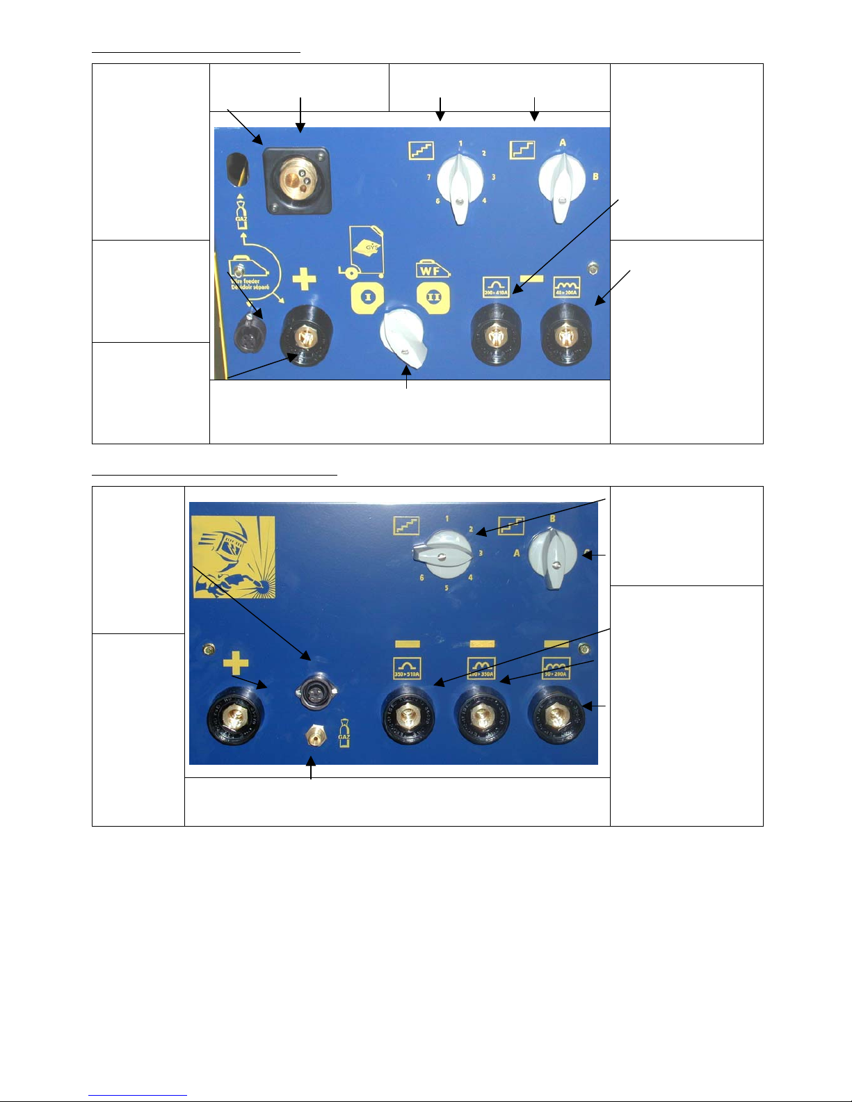
MAGYS 410: Foreside (Lower part)
Generator wire feeder
(connected to positive
terminal).
Selection commutators of the output
voltage.
Gas connection
allows to lay in gas
generator wire
feeder type WF.
The connection is
situated near to the
motor
Terminal – to use a
superior current 200 A
(position for an using in
SPRAY ARC).
Operating
connector for
application with a
separated wire
feeder type WF.
Positive terminal
for an application
with a separated
wire feeder type
WF.
Commutator on wire feeder choice.
Position I: generator wire feeder (origin).
Position II: separated wire feeder WF 212, 324 or 344 W (in
option).
Terminal – application on
weak Thickness (current
inferior to 200 A)
GENEGYS 510 SF: Foreside (Lower part)
Commutator of selection
from the output voltage
Operating
connector for
an application
with a
separated wire
feeder type
WF.
Positive
terminal for
the connection
to contact
batch for an
application
with separated
wire feeder
type WF.
Gas adapter of the bank.
Negative terminal: allows
to select an arc more or
less short.
This terminal depends on
the welding intensity we
are connected.
Page 5

5
GENEGYS 515 WSF : foreside (higher part)
GENEGYS 515 WSF : foreside (lower part)
Selection indicator
of value
(VOLTAGE or
WIRE SPEED)
Indicator of
VOLTAGE or
WIRE SPEED
measurmen
t
Indicator of current
measurmen
t
Switch of selection
for the output
voltage
Button of mode
selection
Indicators of mode
selection : 2 times, 4
times or spot
Control of the
cooling liquid group
Button of WIRE
quick : it allows for
new coils to save
gas
Button of gas drain :
it allows to avoid
impurity during
bottle replacement
or after a long
immobilization
Commutator
On / Off
Yellow indicator of
thermal switching
Button of
spot time
adjustment
Operating connector
for an application
with a separated
wire feeder type
WF.
Gas adapter of the
bank
Filler cap of the cooling
liquid tank
Positive terminal for
the connection to
contact batch for an
application with
separated wire
feeder type WF
N
egative terminal :
allows to select an arc
more or less short.
see
page 9
This terminal depends on
the welding intensity we
are connected
Adapter for cooling
liquid
Page 6

6
IV / COMMISSIONING
4-1) Mains connection
See paragraph III.
4-2) Connection to gas bottle and gas choice
Screw down the regulator on gas bottle. This one is connected to MAGYS and GENEGYS by a pipe whose terminal
end is fixated on the electronic valve behind the machine. You must use clamps to avoid escape of gas.
MAGYS 410
Application with the wire feeder of the generator Application with a separated wire feeder typ WF
Screw down the gas connection from moto generator
wire feeder on the gas connection
Screw off the pipe of moto generator wire feeder and screw
down bank connection by integrating the pipe in the frontside
hole.
For GENEGYS 510 SF and GENEGYS 515 WSF machine, the gas connection of the bank is uniquely made on front
side.
Gas choice:
STEEL MORE OR LESS ALLOYED
- Pure CO2 (not much used),
- Argon + CO2 (universal gas, often used),
- Argon + CO2 + O2 (not much used).
STAINLESS STEEL
- Argon + CO2 (often used),
- Argon + H + CO2 +N (not much used).
ALUMINIUM
- Pure argon (often used),
- Argon + Hé (not much used).
4-3) Connection to earth cable
For an application with a wire in normal polarity, you must connect the adapter earth clamp on the negative terminal
and take care to swivel from a ¼ the adapter.
MAGYS 410 machine can only operate in normal polarity (positive for the motor) if we used the generator wire
feeder.
Page 7

7
GENEGYS 510 SF and GENEGYS WSF machine can be used with a WIRE in reversed polarity by inversing in face
before the connection of the earth clamp and bank.
4-4) Connection of the torch
All torches are with a euro connection, which can be adapted on GYS machines.
4-5) Setting of rollers
Choose those in function of the wire diameter used and the type of wire (See following board). MAGYS 410
machine is delivered with rollers double groove 0,8 / 1 for steel.
4-6) Setting of wire spool
Open the wire feeder compartment. Remove the swivel from the coil support. Take the coil and put it on the support
with taking care to block with base spin, then screw down again the swivel. For an application with a 5Kg coil (or
d=200), put the adapter between the support and the coil. For an application in steel wire place in position the
capillary tube (for an application in aluminium see the paragraph VIII).
Slump the wire in the moto wire feeder entrance. Release the clamping at maximum. Close the plate of the moto wire
feeder. Press on « ADVANCED WIRE » (in foreside) and tighten little by little the clamping handle until the motor
start to drive the wire.
4-7) Brake adjustment from the coil support
You must block this one in function of the weight coil used.
Too blocked: the motor is in difficulty and the WIRE risk not to drive.
1
4 3
2
Page 8

8
Release: the important coil inertia can drive the wire rolling after end welding.
Open the gas. The machine is ready to operate.
4-8)Commissioning of the cooling liquid group ( GENEGYS 515 WSF)
• Never operates the cooling group without filling the cooling liquid tank before the use of the machine.
• Use the cooling liquid -25°C.
• Fill the tank until the maximum level
For first use, the cooling circuit must be bleeded from the water. To do this operation, you have
to connect the blue connection of the contact batch (5 or 10 meters) on the blue connection of the MIG
generator. Inject compressed air in the blue pipe of the contact batch to drive out the air bubble
contained in the pump circuit.
• The pump can be used.
• Connect the blue and red connection of the contact batch to the generator and the wire feeder.
• Control that the water circulation works correctly.
• Check the cooling liquid level before each use of the unit and complete the liquid if necessary.
Page 9

9
V / INDICATIVES ADJUSTEMENTS
ADJUSTMENT FOR MAGYS 410 IN STEEL USING
INDICATIVE
ADJUSTMENT
COMMUTATOR
POSITION
WIRE SPEED
SELF
EXTENSION
Metal
thickness
∅ WIRE to
use
Adjustment Current
obtain (A)
Adjustment Speed obtain
M/MIN
WITH OR
WITHOUT SELF
1 0,8 A1-A2 40-80 1-2 2-4
1,5 0,8 A3-A4 80-110 2-4 4-6
2 0,8-1 A4-A5 100-130 3-5 6-8
3 0,8-1 A5-A6- 130-180 4-5 7-11
4-5 1-1,2 A7-B1 180-230 4-7 7-13
5-7 1-1,2 B1-B2-B3 220-300 4-8 7-15
>7 1,2-1,6 B3-B4-B5-
B6-B7
300-410 5-10 9-18
ADJUSTMENT FOR GENEGYS 510 SF and GENEGYS 515 WSF IN STEEL USING
INDICATIVE
ADJUSTMENT
COMMUTATOR
POSITION
WIRE SPEED
SELF
EXTENSION
Metal
thickness
∅ WIRE to
use
Adjustment Current
obtain (A)
Adjustment Speed obtain
M/MIN
WITH OR
WITHOUT SELF
1 0,8 A1-A2 50-80 1-2 2-4
I
1,5 0,8 A3-A4-A5 70-100 2-4 4-6
I
I
2 0,8-1 A5-A6-A7 90-130 3-5 6-8
I
3 0,8-1 B1-B2 120-160 4-5 7-11
I
4-5 1-1,2 B3-B4-B5 150-250 4-6 7-12
II
5-7 1-1,2 B6-B7 230-330 4-7 7-15
II
7-9 1,2-1,6 C1-C2-C3 300-430 5-8 9-16
II
>9 1,2-1,6 C4-C5-C6-
C7
350-510 7-10 12-20
II
VI / USING IN ALUMINIUM
The torch installation for aluminium is fundamental.
The essential precautions are the following:
- Don’t use the brass capillary tube in the euro adapter, but use
the Teflon envelope, which must come until the moto-wire
feeder roller.
- In ALUMINIUM, use a contact tube of a diameter
immediately superior to the section of the wire used.
- Use ALU rollers identical with wire diameter.
VII / OPTION FOR MAGYS 410
MAGYS 410 machine is an evolutive terminal. For origin machine, we can uniquely use this one with the moto wire
feeder. Then, we can advanced the product with separated wire feeder with equipping it with a WF wire feeder and a
contact batch from 5 or 10 meters.
Page 10

10
When the machine is totally equipped, the choice of the moto wire feeder will be in function of the commutator
position in foreside.
Connection from a wire feeder WF to the generator
VIII / MAINTENANCE
You must clean out and replace regularly nozzle and contact batch of all projections. Use a spray of anti-pearl
aerosol.
We advice you to clean the covering situated in the torch by blowing it with compressed air.
IX / ADJUSTMENTS OF WELDING CYCLES: PREGAZ, POSTGAZ, BURNBACK
The evoluated electronic card of MAGYS 410 and GENEGYS 510 SF machines allows intervening on welding
parameters.
To go on ADJUSTMENT mode, you have to (when the machine is working) press during 3 seconds on the button
« MODE ». Then, every indicators switch off and the higher display indicate PRE and the lower display indicate the
PREGAZ value. This value can be modified by pressing on + or -. If you press again on, you will adjust the
POSTGAZ time (POS on the higher display). If you press a third time, you will adjust the late time to the fusion
(BURNBACK) or the free WIRE length (Bur on the higher display). To come back in normal mode, you have to
press again on MODE.
If, by mistake, the modified parameters doesn’t correspond anymore to the user wishes, you can put back the
welding parameters from the factory.
For that, you must switch off the machine. Then, you have to press on the button MODE and + and switch on the
machine by pressing a long time buttons MODE and +. After that, the values PRE, POS and Bur clear out. Now, you
can release buttons. News parameters are also enter in the machine.
Origin moto-wire feeder on
the generator
Option wire feeder WF
Gas pipe
Control cable
Power cable
To use a wire feeder WF,
tip the commutator on the
position II « wire feeder
WF
»
Don’t forget to transpose
the gas connection
situated behind the front
panel
Page 11

11
X / MAINTENANCE: symptoms, reason, solution
SYMPTOMS
POSSIBLE REASONS
SOLUTIONS
The welding wire debit
is not constant
-cracklings block up the opening.
-The wire skid in the rollers.
-Clean out the contact batch or change it
and replace the anti-adherence product.
-Control the rollers pressure or replace it.
-Wire diameter non-consonant with
roller.
-Covering wire guide in the torch non-
consonant.
The unwinding motor
doesn’t operate.
-Coil brake too block.
-Others.
-Release the brake.
-Check that the running button is on the
position on.
-Release the rollers.
Bad wire unwinding. -Covering wire guide dirty or
damaged.
- Coil brake too block.
-Clean out or replace.
-Release the brake
No welding current. -Bad connection of the main
connection.
-Bad earth connection.
-Power contactor inoperative.
-See the branch connection and look if
the lap is fed by 3 phases.
-Control the earth cable (connection and
clamp state).
-Control the torch gate.
The WIRE rubs down
after the rollers.
-Covering WIRE guide crushed.
-Locking of the WIRE in the torch.
-No capillary tube.
-WIRE quick too important.
-Replace or clean out.
-Check the covering and torch body.
-Check the presence of capillary tube.
The welding cord is
porous.
- The gas debit is insufficient.
-Gas bottle empty.
-Gas quality non-satisfying.
-Air circulation or wind influence.
-Gas nozzle too foul.
-Bad WIRE quality.
-Bad quality of the area state to weld
(rust, etc…)
-From 15 to 20 L / min.
-Replace it.
-Replace it.
-Avert air blast, protect welding area.
-Clean the gas nozzle or replace it.
-Use adapted WIRE for MIG-MAG
welding.
-Clean the bases metal.
Very important flashing
particules.
-Arc power too low or too high.
-Bad earth connection.
-Protecting gas insufficient.
-See welding parameters.
-Control if it is possible to have a better
earth connection.
-Adjust gas debit.
No gas in torch outlet - Bad gas connection - (On MAGYS 410) see if the gas
junction near to the motor is correctly
connected.
 Loading...