

Page 1
FR
2-3 / 4-12 / 65-75
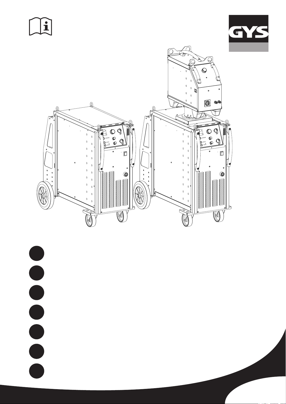
MAGYS 400-4
EN
DE
ES
RU
IT
NL
73502-V5.1-10/12/2018
2-3 / 13-20 / 65-75
2-3 / 21-29 / 65-75
2-3 / 30-38 / 65-75
2-3 / 39-47 / 65-75
2-3 / 48-55 / 65-75
2-3 / 56-64 / 65-75
MAGYS 400 GR
MAGYS 500 GR
MAGYS 500 WS
www.gys.fr
Page 2
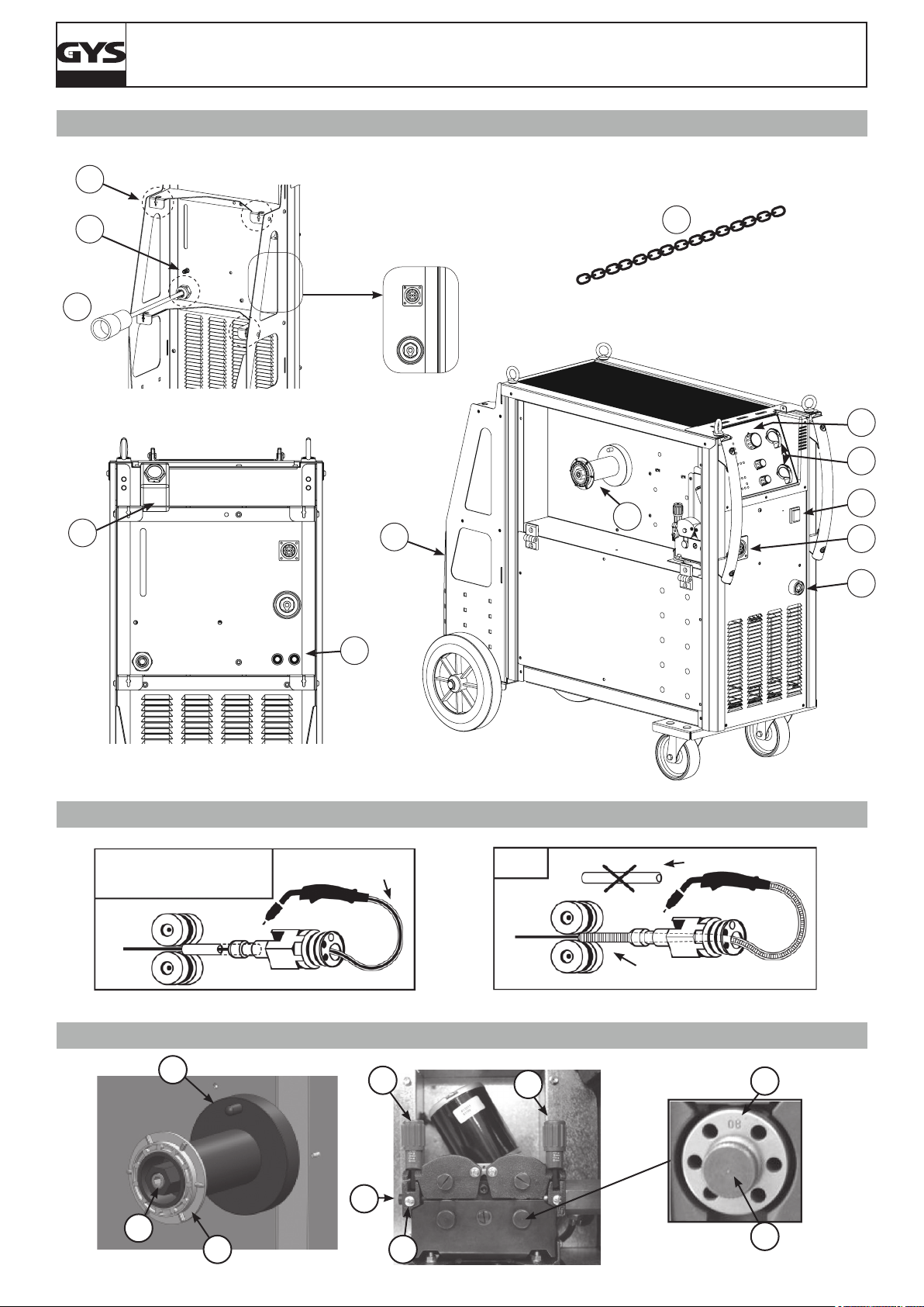
FIG - 1
13
MAGYS 400-4 / 400 GR / 500 GR / 500 WS
10
5
12
MAGYS 500 WS
MAGYS 400 GR
MAGYS 500 GR
7
11
8
MAGYS 400-4
x2
3
2
1
9
4
6
FIG - 2
- Acier / Steel / Stahl / Acero
/ Staal / Aço
- Inox - Stainless steel
A/
FIG - 3
1
2
Gaine acier / Steel
sheath / Stahlseele
8
B/
- Alu
NO USE
Gaine téon / Teon sheath
/ Teonseele
8
Tube capillaire / Capillary Pipe
/ Kapillarrohr
4
7
6
3
5
2
Page 3
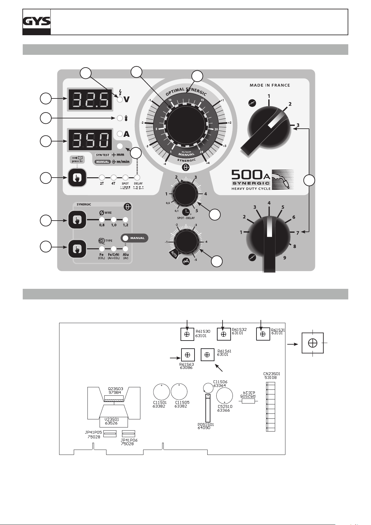
FIG - 4
MAGYS 400-4 / 400 GR / 500 GR / 500 WS
9
8
10
1
7
5
13
2
11
6
12
3
FIG - 5
P4
4
P1 P2 P3
0%
50%
100%
P5
3
Page 4
MAGYS 400-4 / 400 GR / 500 GR / 500 WS
FR
AVERTISSEMENTS - RÈGLES DE SÉCURITÉ
CONSIGNE GÉNÉRALE
Ces instructions doivent être lues et bien comprises avant toute opération.
Toute modication ou maintenance non indiquée dans le manuel ne doit pas être entreprise.
Tout dommage corporel ou matériel dû à une utilisation non-conforme aux instructions de ce manuel ne pourra être retenu à la charge du fabricant.
En cas de problème ou d’incertitude, consulter une personne qualiée pour manier correctement l’installation.
ENVIRONNEMENT
Ce matériel doit être utilisé uniquement pour faire des opérations de soudage dans les limites indiquées par la plaque signalétique et/ou le manuel.
Il faut respecter les directives relatives à la sécurité. En cas d’utilisation inadéquate ou dangereuse, le fabricant ne pourra être tenu responsable.
L’installation doit être utilisée dans un local sans poussière, ni acide, ni gaz inammable ou autres substances corrosives. Il en est de même pour son
stockage. S’assurer d’une circulation d’air lors de l’utilisation.
Plages de température :
Utilisation entre -10 et +40°C (+14 et +104°F).
Stockage entre -20 et +55°C (-4 et 131°F).
Humidité de l’air :
Inférieur ou égal à 50% à 40°C (104°F).
Inférieur ou égal à 90% à 20°C (68°F).
Altitude :
Jusqu’à 1000 m au-dessus du niveau de la mer (3280 pieds).
PROTECTION INDIVIDUELLE ET DES AUTRES
Le soudage à l’arc peut être dangereux et causer des blessures graves voire mortelles.
Le soudage expose les individus à une source dangereuse de chaleur, de rayonnement lumineux de l’arc, de champs électromagnétiques (attention
au porteur de pacemaker), de risque d’électrocution, de bruit et d’émanations gazeuses.
Pour bien se protéger et protéger les autres, respecter les instructions de sécurité suivantes :
An de se protéger de brûlures et rayonnements, porter des vêtements sans revers, isolants, secs, ignifugés et en bon état, qui
couvrent l’ensemble du corps.
Utiliser des gants qui garantissent l’isolation électrique et thermique.
Utiliser une protection de soudage et/ou une cagoule de soudage d’un niveau de protection sufsant (variable selon les applications).
Protéger les yeux lors des opérations de nettoyage. Les lentilles de contact sont particulièrement proscrites.
Il est parfois nécessaire de délimiter les zones par des rideaux ignifugés pour protéger la zone de soudage des rayons de l’arc, des
projections et des déchets incandescents.
Informer les personnes dans la zone de soudage de ne pas xer les rayons de l’arc ni les pièces en fusion et de porter les vêtements
adéquats pour se protéger.
Utiliser un casque contre le bruit si le procédé de soudage atteint un niveau de bruit supérieur à la limite autorisée (de même pour
toute personne étant dans la zone de soudage).
Tenir à distance des parties mobiles (ventilateur) les mains, cheveux, vêtements.
Ne jamais enlever les protections carter du groupe froid lorsque la source de courant de soudage est sous tension, le fabricant ne
pourrait être tenu pour responsable en cas d’accident.
Les pièces qui viennent d’être soudées sont chaudes et peuvent provoquer des brûlures lors de leur manipulation. Lors d’intervention
d’entretien sur la torche ou le porte-électrode, il faut s’assurer qu’il/elle soit sufsamment froid(e) en attendant au moins 10 minutes
avant toute intervention. Le groupe froid doit être allumé lors de l’utilisation d’une torche refroidie eau an d’être sûr que le liquide
ne puisse pas causer de brûlures.
Il est important de sécuriser la zone de travail avant de la quitter an de protéger les personnes et les biens.
FUMÉES DE SOUDAGE ET GAZ
Les fumées, gaz et poussières émis par le soudage sont dangereux pour la santé. Il faut prévoir une ventilation sufsante, un
apport d’air est parfois nécessaire. Un masque à air frais peut être une solution en cas d’aération insufsante.
Vérier que l’aspiration est efcace en la contrôlant par rapport aux normes de sécurité.
Attention le soudage dans les environnements réduits nécessite une surveillance à distance de sécurité. Par ailleurs le soudage de certains matériaux
contenant du plomb, cadmium, zinc ou mercure voire du béryllium peuvent être particulièrement nocifs.
Dégraisser également les pièces avant de les souder.
Les bouteilles doivent être entreposées dans des locaux ouverts ou bien aérés. Elles doivent être en position verticale et maintenues à un support ou
sur un chariot.
Le soudage doit être proscrit à proximité de graisse ou de peinture.
4
Page 5
MAGYS 400-4 / 400 GR / 500 GR / 500 WS
FR
RISQUE DE FEU ET D’EXPLOSION
Protéger entièrement la zone de soudage, les matières inammables doivent être éloignées d’au moins 11 mètres.
Un équipement anti-feu doit être présent à proximité des opérations de soudage.
Attention aux projections de matières chaudes ou d’étincelles, car même à travers des ssures, elles peuvent être source
d’incendie ou d’explosion.
Éloigner les personnes, les objets inammables et les containers sous pressions à une distance de sécurité sufsante.
Le soudage dans des containers ou des tubes fermés est à proscrire et dans le cas où ils sont ouverts, il faut les vider de toute matière inammable
ou explosive (huile, carburant, résidus de gaz …).
Les opérations de meulage ne doivent pas être dirigées vers la source de courant de soudage ou vers des matières inammables.
BOUTEILLES DE GAZ
Le gaz sortant des bouteilles peut être source de suffocation en cas de concentration dans l’espace de soudage (bien ventiler).
Le transport doit être fait en toute sécurité : bouteilles fermées et la source de courant de soudage éteinte. Elles doivent être
entreposées verticalement et maintenues par un support pour limiter le risque de chute.
Fermer la bouteille entre deux utilisations. Attention aux variations de température et aux expositions au soleil.
La bouteille ne doit pas être en contact avec une amme, un arc électrique, une torche, une pince de masse ou toutes autres sources de chaleur ou
d’incandescence.
Veiller à la tenir éloignée des circuits électriques et de soudage et donc ne jamais souder une bouteille sous pression.
Attention lors de l’ouverture du robinet de la bouteille, il faut éloigner la tête la robinetterie et s’assurer que le gaz utilisé est approprié au procédé
de soudage.
SÉCURITÉ ÉLECTRIQUE
Le réseau électrique utilisé doit impérativement avoir une mise à la terre. Utiliser la taille de fusible recommandée sur le tableau
signalétique.
Une décharge électrique peut être une source d’accident grave direct ou indirect, voire mortel.
Ne jamais toucher les parties sous tension à l’intérieur comme à l’extérieur de la source de courant sous-tension (Torches, pinces, câbles, électrodes)
car celles-ci sont branchées au circuit de soudage.
Avant d’ouvrir la source de courant de soudage, il faut la déconnecter du réseau et attendre 2 minutes. an que l’ensemble des condensateurs soit
déchargé.
Ne pas toucher en même temps la torche ou le porte-électrode et la pince de masse.
Veiller à changer les câbles et torches, par des personnes qualiées et habilitées, si ceux-ci sont endommagés. Dimensionner la section des câbles
en fonction de l’application. Toujours utiliser des vêtements secs et en bon état pour s’isoler du circuit de soudage. Porter des chaussures isolantes,
quel que soit le milieu de travail.
CLASSIFICATION CEM DU MATERIEL
Ce matériel de Classe A n’est pas prévu pour être utilisé dans un site résidentiel où le courant électrique est fourni par le réseau
public d’alimentation basse tension. Il peut y avoir des difcultés potentielles pour assurer la compatibilité électromagnétique
dans ces sites, à cause des perturbations conduites, aussi bien que rayonnées à fréquence radioélectrique.
Ce matériel est conforme à la CEI 61000-3-12, à condition que la puissance de court-circuit Ssc soit supérieure ou égale à
3.9 MVA au point d’interface entre l’alimentation de l’utilisateur et le réseau public de distribution. Il est de la responsabilité de
l’installateur ou de l’utilisateur du matériel de s’assurer, si nécessaire en consultant l’exploitant du réseau de distribution, que le
matériel est raccordé uniquement à une alimentation ayant une puissance de court-circuit Ssc supérieure ou égale à 3.9 MVA.
Ce matériel est conforme à la CEI 61000-3-11.
ÉMISSIONS ÉLECTROMAGNÉTIQUES
Le courant électrique passant à travers n’importe quel conducteur produit des champs électriques et magnétiques (EMF) localisés.
Le courant de soudage produit un champ électromagnétique autour du circuit de soudage et du matériel de soudage.
Les champs électromagnétiques EMF peuvent perturber certains implants médicaux, par exemple les stimulateurs cardiaques. Des mesures de
protection doivent être prises pour les personnes portant des implants médicaux. Par exemple, restrictions d’accès pour les passants ou une évaluation
de risque individuelle pour les soudeurs.
Tous les soudeurs doivent utiliser les procédures suivantes an de minimiser l’exposition aux champs électromagnétiques provenant du circuit de
soudage:
• positionner les câbles de soudage ensemble – les xer avec une attache, si possible;
• se positionner (torse et tête) aussi loin que possible du circuit de soudage;
• ne jamais enrouler les câbles de soudage autour du corps;
• ne pas positionner le corps entre les câbles de soudage. Tenir les deux câbles de soudage sur le même côté du corps;
• raccorder le câble de retour à la pièce mise en œuvre aussi proche que possible à la zone à souder;
5
Page 6
MAGYS 400-4 / 400 GR / 500 GR / 500 WS
• ne pas travailler à côté de la source de courant de soudage, ne pas s’assoir dessus ou ne pas s’y adosser;
• ne pas souder lors du transport de la source de courant de soudage ou le dévidoir.
Les porteurs de stimulateurs cardiaques doivent consulter un médecin avant d’utiliser ce matériel.
L’exposition aux champs électromagnétiques lors du soudage peut avoir d’autres effets sur la santé que l’on ne connaît pas
encore.
FR
RECOMMANDATIONS POUR ÉVALUER LA ZONE ET L’INSTALLATION DE SOUDAGE
Généralités
L’utilisateur est responsable de l’installation et de l’utilisation du matériel de soudage à l’arc suivant les instructions du fabricant. Si des perturbations
électromagnétiques sont détectées, il doit être de la responsabilité de l’utilisateur du matériel de soudage à l’arc de résoudre la situation avec
l’assistance technique du fabricant. Dans certains cas, cette action corrective peut être aussi simple qu’une mise à la terre du circuit de soudage. Dans
d’autres cas, il peut être nécessaire de construire un écran électromagnétique autour de la source de courant de soudage et de la pièce entière avec
montage de ltres d’entrée. Dans tous les cas, les perturbations électromagnétiques doivent être réduites jusqu’à ce qu’elles ne soient plus gênantes.
Evaluation de la zone de soudage
Avant d’installer un matériel de soudage à l’arc, l’utilisateur doit évaluer les problèmes électromagnétiques potentiels dans la zone environnante. Ce
qui suit doit être pris en compte:
a) la présence au-dessus, au-dessous et à côté du matériel de soudage à l’arc d’autres câbles d’alimentation, de commande, de signalisation et de
téléphone;
b) des récepteurs et transmetteurs de radio et télévision;
c) des ordinateurs et autres matériels de commande;
d) du matériel critique de sécurité, par exemple, protection de matériel industriel;
e) la santé des personnes voisines, par exemple, emploi de stimulateurs cardiaques ou d’appareils contre la surdité;
f) du matériel utilisé pour l’étalonnage ou la mesure;
g) l’immunité des autres matériels présents dans l’environnement.
L’utilisateur doit s’assurer que les autres matériels utilisés dans l’environnement sont compatibles. Cela peut exiger des mesures de protection
supplémentaires;
h) l’heure du jour où le soudage ou d’autres activités sont à exécuter.
La dimension de la zone environnante à prendre en compte dépend de la structure du bâtiment et des autres activités qui s’y déroulent. La zone
environnante peut s’étendre au-delà des limites des installations.
Evaluation de l’installation de soudage
Outre l’évaluation de la zone, l’évaluation des installations de soudage à l’arc peut servir à déterminer et résoudre les cas de perturbations. Il convient
que l’évaluation des émissions comprenne des mesures in situ comme cela est spécié à l’Article 10 de la CISPR 11:2009. Les mesures in situ peuvent
également permettre de conrmer l’efcacité des mesures d’atténuation.
RECOMMANDATION SUR LES MÉTHODES DE REDUCTION DES EMISSIONS ÉLECTROMAGNÉTIQUES
a. Réseau public d’alimentation: Il convient de raccorder le matériel de soudage à l’arc au réseau public d’alimentation selon les recommandations
du fabricant. Si des interférences se produisent, il peut être nécessaire de prendre des mesures de prévention supplémentaires telles que le ltrage
du réseau public d’alimentation. Il convient d’envisager de blinder le câble d’alimentation dans un conduit métallique ou équivalent d’un matériel de
soudage à l’arc installé à demeure. Il convient d’assurer la continuité électrique du blindage sur toute sa longueur. Il convient de raccorder le blindage
à la source de courant de soudage pour assurer un bon contact électrique entre le conduit et l’enveloppe de la source de courant de soudage.
b. Maintenance du matériel de soudage à l’arc : Il convient que le matériel de soudage à l’arc soit soumis à l’entretien de routine suivant les
recommandations du fabricant. Il convient que tous les accès, portes de service et capots soient fermés et correctement verrouillés lorsque le matériel
de soudage à l’arc est en service. Il convient que le matériel de soudage à l’arc ne soit modié en aucune façon, hormis les modications et réglages
mentionnés dans les instructions du fabricant. Il convient, en particulier, que l’éclateur d’arc des dispositifs d’amorçage et de stabilisation d’arc soit
réglé et entretenu suivant les recommandations du fabricant.
c. Câbles de soudage : Il convient que les câbles soient aussi courts que possible, placés l’un près de l’autre à proximité du sol ou sur le sol.
d. Liaison équipotentielle : Il convient d’envisager la liaison de tous les objets métalliques de la zone environnante. Toutefois, des objets métalliques
reliés à la pièce à souder accroissent le risque pour l’opérateur de chocs électriques s’il touche à la fois ces éléments métalliques et l’électrode. Il
convient d’isoler l’opérateur de tels objets métalliques.
e. Mise à la terre de la pièce à souder : Lorsque la pièce à souder n’est pas reliée à la terre pour la sécurité électrique ou en raison de ses
dimensions et de son emplacement, ce qui est le cas, par exemple, des coques de navire ou des charpentes métalliques de bâtiments, une connexion
raccordant la pièce à la terre peut, dans certains cas et non systématiquement, réduire les émissions. Il convient de veiller à éviter la mise à la terre
des pièces qui pourrait accroître les risques de blessure pour les utilisateurs ou endommager d’autres matériels électriques. Si nécessaire, il convient
que le raccordement de la pièce à souder à la terre soit fait directement, mais dans certains pays n’autorisant pas cette connexion directe, il convient
que la connexion soit faite avec un condensateur approprié et choisi en fonction des réglementations nationales.
f. Protection et blindage : La protection et le blindage sélectifs d’autres câbles et matériels dans la zone environnante peuvent limiter les problèmes
de perturbation. La protection de toute la zone de soudage peut être envisagée pour des applications spéciales.
TRANSPORT ET TRANSIT DE L’APPAREIL
Ne pas utiliser les câbles ou torche pour déplacer la source de courant de soudage. Elle doit être déplacée en position verticale.
Ne pas faire transiter la source de courant au-dessus de personnes ou d’objets.
Ne jamais soulever une bouteille de gaz et la source de courant en même temps. Leurs normes de transport sont distinctes.
Il est préférable d’enlever la bobine de l avant tout levage ou transport de la source de courant de soudage.
6
Page 7
MAGYS 400-4 / 400 GR / 500 GR / 500 WS
La source de tension de soudage est équipée d’une (de) poignée(s) / sangle(s) supérieure(s) permettant le portage à la main. Attention à ne pas
sous-évaluer son poids. La (les) poignée(s) / sangle(s) n’est (ne sont) pas considérée(s) comme un moyen d’élingage.
Les courants de soudage vagabonds peuvent détruire les conducteurs de terre, endommager l’équipement et les dispositifs électriques et causer des
échauffements de composants pouvant entrainer un incendie.
- Toutes les connexions de soudages doivent être connectées fermement, les vérier régulièrement !
- S’assurer que la xation de la pièce est solide et sans problèmes électriques !
- Attacher ou suspendre tous les éléments conducteurs d’électricité de la source de soudage comme le châssis, le chariot et les systèmes de levage
pour qu’ils soient isolés !
- Ne pas déposer d’autres équipements comme des perceuses, dispositifs d’affutage, etc sur la source de soudage, le chariot, ou les systèmes de
levage sans qu’ils soient isolés !
- Toujours déposer les torches de soudage ou portes électrodes sur une surface isolée quand ils ne sont pas utilisés ! »
FR
INSTALLATION DU MATÉRIEL
• Mettre la source de courant de soudage sur un sol dont l’inclinaison maximum est de 10°.
• Prévoir une zone sufsante pour aérer la source de courant de soudage et accéder aux commandes.
• La source de courant de soudage doit être à l’abri de la pluie battante et ne pas être exposée aux rayons du soleil.
• Ne pas utiliser dans un environnement comportant des poussières métalliques conductrices.
• Le matériel est de degré de protection IP23, signiant :
- une protection contre l’accès aux parties dangereuses des corps solides de Ø >12.5mm et,
- une protection contre la pluie dirigée à 60% par rapport à la verticale.
Ce matériel peut donc être utilisé à l’extérieur en accord avec l’indice de protection IP23.
• N’utilisez pas les postes à des températures > 40°C.
• Les câbles d’alimentation, de rallonge et de soudage doivent être totalement déroulés an d’éviter toute surchauffe.
Le fabricant n’assume aucune responsabilité concernant les dommages provoqués à des personnes et objets dus à une utilisation
incorrecte et dangereuse de ce matériel.
ENTRETIEN / CONSEILS
• L’entretien ne doit être effectué que par une personne qualiée. Un entretien annuel est conseillé.
• Couper l’alimentation en débranchant la prise, et attendre deux minutes avant de travailler sur le matériel. A l’intérieur, les
tensions et intensités sont élevées et dangereuses.
• Régulièrement, enlever le capot et dépoussiérer à la soufette. En proter pour faire vérier la tenue des connexions électriques avec un outil isolé
par un personnel qualié.
• Contrôler régulièrement l’état du cordon d’alimentation. Si le câble d’alimentation est endommagé, il doit être remplacé par le fabricant, son service
après-vente ou une personne de qualication similaire, an d’éviter tout danger.
• Laisser les ouïes de la source de courant de soudage libres pour l’entrée et la sortie d’air.
• Ne pas utiliser cette source de tension de soudage pour dégeler des canalisations, recharger des batteries/accumulateurs ou démarrer des moteurs.
INSTALLATION – FONCTIONNEMENT PRODUIT
Seul le personnel expérimenté et habilité par le fabricant peut effectuer l’installation. Pendant l’installation, s’assurer que le générateur est déconnecté
du réseau.
DESCRIPTION
Les Magys sont des postes de soudure semi-automatique « synergic » sur roues, ventilés pour le soudage (MIG ou MAG). Ils fonctionnent sur une
alimentation 400 V triphasée.
Pour fonctionner le générateur MAGYS :
• 400 GR doit être utilisé avec le dévidoir séparé WS-4R (ref. 034723) ou W5S-4L (réf 032835) et un faisceau de liaison.
• 500 GR doit être utilisé avec le dévidoir séparé WS-4R (ref. 034723) ou W5S-4L (réf 032835) et un faisceau de liaison.
• 500 WS doit être utilisé avec le dévidoir séparé WS-4L (ref. 033573) ou W5S-4L (réf 032835) et un faisceau de liaison.
ALIMENTATION ÉLECTRIQUE
Ce matériel est livré avec prise 32 A de type EN 60309-1 et ne doit être utilisé que sur une installation électrique triphasée 400V (50-60 Hz) à quatre
ls avec un neutre relié à la terre.
Le courant effectif absorbé (I1eff) est indiqué sur le matériel, pour les conditions d’utilisation maximales. Vérier que l’alimentation et ses protections
(fusible et/ou disjoncteur) sont compatibles avec le courant nécessaire en utilisation. Dans certains pays, il peut être nécessaire de changer la prise
pour permettre une utilisation aux conditions maximales.
• La source de puissance est prévue pour fonctionner sur une tension électrique 400V +/- 15%. Elle se met en protection si la tension d’alimentation
est inférieure à 330 Veff ou supérieure à 490Veff.
• La mise en marche se fait par rotation du commutateur marche/ arrêt (1 - FIG 1) sur la position I, inversement l’arrêt se fait par une rotation sur la
position 0. Attention ! Ne jamais couper l’alimentation lorsque le poste est en charge.
• Comportement du ventilateur : Les générateurs MAGYS 400-4 / 400 GR et 500 GR sont équipés d’une gestion intelligente de la ventilation dans le
but de minimiser le bruit du poste. La ventilation reste activée pendant 10 minutes puis s’arrête automatiquement. Si l’utilisateur appuie sur la touche
de changement de mode (1 - FIG 4), cela coupe le refroidissement immédiatement. Il sera remis en marche au cordon de soudage suivant. Même
comportement pour le MAGYS 500 WS et son système de refroidissement (groupe froid et ventilateur).
BRANCHEMENT SUR GROUPE ÉLECTROGÈNE
Le poste peut fonctionner avec des groupes électrogènes à condition que la puissance auxiliaire réponde aux exigences suivantes :
- La tension doit être alternative, sa valeur efcace doit être de 400V +/- 15%, et de tension crête inférieure à 700 V,
- La fréquence doit être comprise entre 50 et 60 Hz.
7
Page 8

MAGYS 400-4 / 400 GR / 500 GR / 500 WS
Il est impératif de vérier ces conditions, car de nombreux groupes électrogènes produisent des pics de haute tension pouvant endommager les
postes.
FR
UTILISATION DE RALLONGE ÉLECTRIQUE
Toutes les rallonges doivent avoir une taille et une section appropriées à la tension de l’appareil.
Utiliser une rallonge conforme aux réglementations nationales.
Tension d’entrée Section de la rallonge (<45m)
400 V 6 mm²
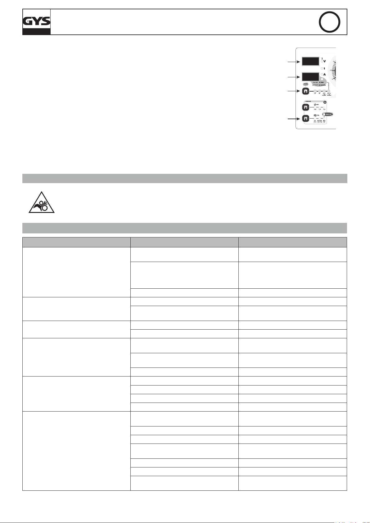
MONTAGE ET DESCRIPTION DU POSTE (FIG 1)
Mettre le tapis (uniquement pour le Magys 400-4) et les 4 anneaux de levage (avec leur rondelles). La bouteille de gaz se xe à l’aide de 2 chaînes à
insérer dans les encoches prévues à cet effet. Attention : bien xer la bouteille. Il existe aussi des ouvertures pour passer des sangles (non fournies).
1- Interrupteur marche – arrêt 8- Chaines de xation pour bouteille.
2 commutateurs de réglage permettent d’ajuster
2-
la tension de soudage en sortie de générateur.
3- Clavier de réglage des paramètres de soudage. 10-
4- Raccord torche au standard européen. 11- Entrée et sortie d’eau (Magys 500 WS)
5- Câble d’alimentation (5 m) 12- Réservoir 5,5 L (Magys 500 WS)
6- Sortie pince de masse. 13- Encoches de xation pour chaînes
7- Support bouteille (bouteille de 10 m
3
max).
9- Support bobine Ø 200/300 mm.
Entrée gaz (Pour le Magys 500 WS, le tuyau gaz se raccorde directement au manomètre de la bouteille).
SOUDAGE SEMI-AUTOMATIQUE EN ACIER / INOX (MODE MAG) (FIG-2-A)
Les MAGYS sont livrés d’origine pour fonctionner avec du l Ø 1 mm en acier (galets réversible Ø 1/1,2 acier/inox). S’assurer que l’ensemble galet,
gaine, tube contact soit compatible avec le diamètre de l utilisé.
L’utilisation en acier ou inox nécessite un gaz spécique au soudage argon + CO2 (Ar + CO2) mais d’autres combinaisons sont possibles. La proportion de CO2 varie selon l’utilisation. Pour le choix du gaz, demander conseil à un distributeur de gaz. Le débit de gaz pour le soudage en acier se situe
entre 15 et 25 L/min selon les conditions de soudage.
Pour les ls de diamètre > 1.6 mm, il est recommandé de retirer le tube capillaire.
SOUDAGE SEMI-AUTOMATIQUE ALUMINIUM (FIG-2-B)
Cet appareil peut souder du l aluminium de 1 mm et plus.
Pour souder l’aluminium, il faut utiliser un gaz neutre: argon pur (Ar) mais d’autres combinaisons sont possibles. Pour le choix du gaz, demander
conseil à un distributeur de gaz. Le débit du gaz se situe entre 20 et 25 L/min selon les conditions de soudage.
- An de ne pas écraser le l, mettre un minimum sur les galets presseurs du moto-dévidoir.
- Retirer le tube capillaire avant de connecter la torche aluminium avec une gaine en téon.
- Utiliser une torche spéciale aluminium qui possède une gaine téon an de réduire les frottements.
NE PAS couper la gaine au bord du raccord ! Cette gaine sert à guider le l à partir des galets.
- Tube contact : utiliser un tube contact SPECIAL aluminium correspondant au diamètre du l.
- Utiliser des galets spéciaux pour l’aluminium.
PROCÉDURE DE MONTAGE DES BOBINES ET DES TORCHES (FIG-3)
• Positionner la bobine en tenant compte de l’ergot d’entrainement (1) du support bobine. Pour monter une bobine de Ø 200mm sur le dévidoir WS-4R
ou WS-4L, installer au préalable un adaptateur sur le support (ref. 042889).
• Régler le frein de la bobine (2) pour éviter lors de l’arrêt de la soudure que l’inertie de la bobine n’emmêle le l. Serrer ensuite fermement l’écrou
de maintien (3).
• Pour la première mise en service :
- desserrer la vis de xation du guide l (5)
- placer les galets, bien serrer leur vis de maintien (6)
- puis positionner le guide l (7) au plus près du galet mais sans contact avec ce dernier, puis resserrer la vis de xation.
• Pour régler la molette des galets presseurs (8), bloquer le l en sortie de torche, actionner le moteur. Le réglage du serrage est bon lorsque les
galets patinent sur le l même si le l est bloqué en bout de torche.
NOTA : Gâchette pressée, si le poste ne détecte pas de contact au bout de 4 secondes, il bascule sur le mode « avance rapide » jusqu’au relâchement
de la gâchette. Le gaz se coupe pendant cette opération.
ATTENTION : Pendant cette avance rapide, le l est sous tension, il faut impérativement éviter tout contact avec les pièces métalliques environ-
nantes.
RACCORDEMENT GAZ
Visser le manodétendeur sur la bouteille de gaz si besoin est, puis connecter le tuyau fourni au raccord gaz (cf (10), FIG-1 pour le MAGYS 400-4).
Pour éviter toute fuite de gaz, utiliser les colliers fournis dans la boîte d’accessoires.
REFROIDISSEMENT LIQUIDE (MAGYS 500 WS) (FIG-3) ET PROTECTION THERMIQUE
Connecter les raccords bleu & rouge du faisceau au générateur (11) et au dévidoir séparé (voir Notice WS-4L/W5S-4L)
Remplir le réservoir (12) jusqu’à son niveau maximum (5,5L de contenance). Le liquide de refroidissement recommandé par GYS (ref.
8
Page 9
MAGYS 400-4 / 400 GR / 500 GR / 500 WS
052246), doit impérativement être utilisé. L’utilisation de liquides de refroidissement autres, et en particulier du liquide standard automobile, peut
conduire, par un phénomène d’électrolyse, à l’accumulation de dépôts solides dans le circuit de refroidissement, dégradant ainsi le refroidissement,
et pouvant aller jusqu’à l’obstruction du circuit.
Toute dégradation de la machine liée à l’utilisation d’un autre liquide de refroidissement ne sera pas considérée dans le cadre de la garantie.
Le MAGYS 500 WS n’est pas préconisé pour fonctionner avec une torche refroidie air.
Si malgré tout une torche air devait être utilisée, un by-pass est livré avec le poste (en face arrière). Le raccorder entre les raccords
bleu et rouge. En cas de non respect de cette consigne, la pompe sera endommagée, et cette panne ne sera pas prise en compte
dans le cadre de la garantie.
FR
Pour le MAGYS 500 WS NE JAMAIS UTILISER VOTRE POSTE SANS LIQUIDE DE REFROIDISSEMENT
lorsque la pompe est en fonctionnement. Respecter le niveau minimal (jauge face arrière)
En cas de non respect, vous risquez de détériorer de manière dénitive la pompe du système de refroidissement.
• Respecter les règles classiques du soudage.
• Laisser les ouïes de l'appareil libres pour l’entrée et la sortie d’air.
• Laisser l’appareil branché quelques minutes après soudage pour permettre le refroidissement.
• Protection thermique : Le voyant (8) Fig-4 s’allume lorsque le poste se met en sécurité. La durée de refroidissement (ventilation forcée) est par
cycles de 10 minutes en fonction de la température ambiante pour le 400-4 et à 20 minutes (ventilation forcée + pompe) pour le MAGYS 400 GR/500
GR/500 WS.
• Ventilation : La ventilation n’est active que lors du soudage et par cycles de refroidissement.
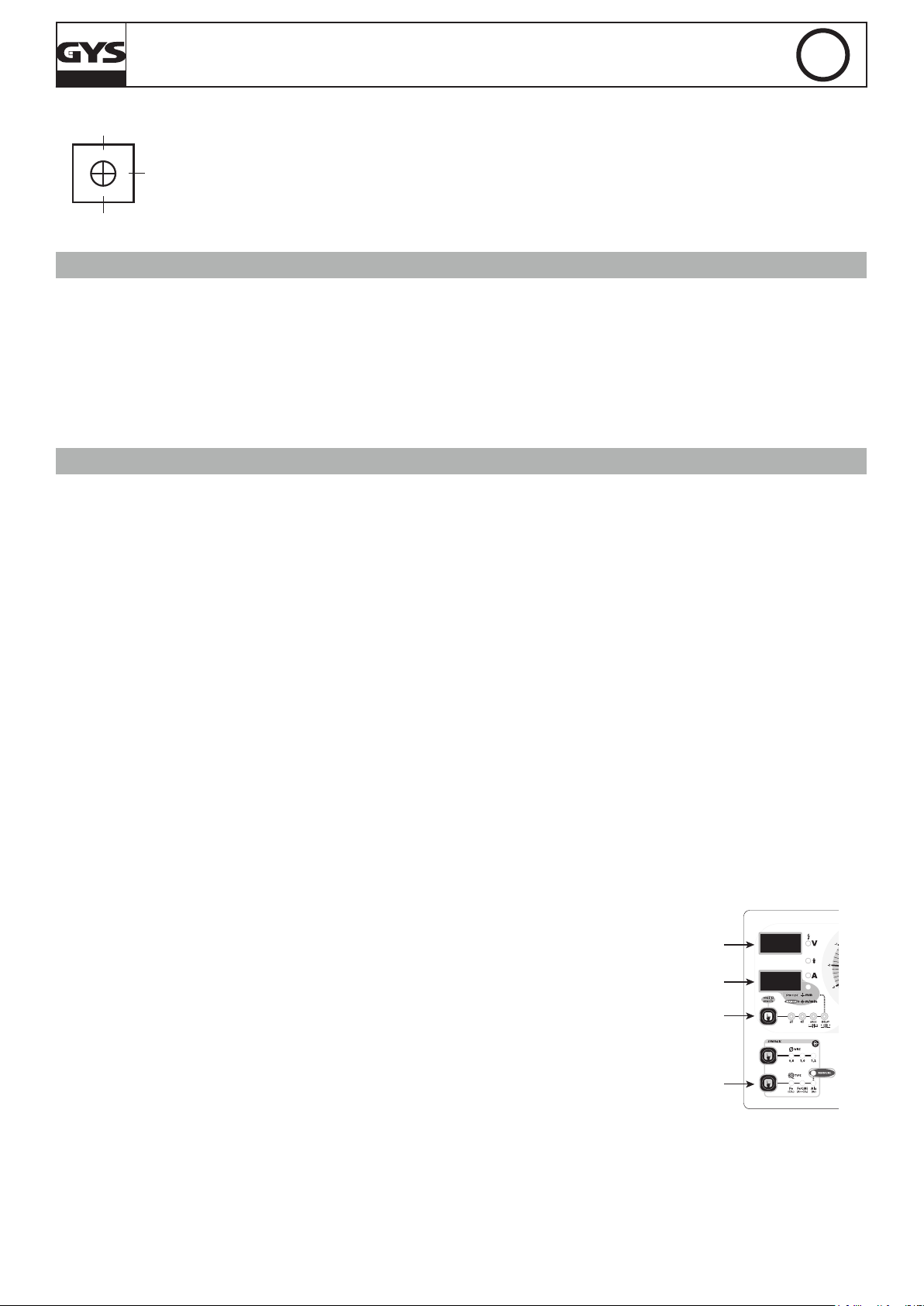
CLAVIER DE COMMANDE (FIG-4)
Choix du mode de soudage / test :
-2T : soudage 2 temps / 4T : soudage 4 temps.
-SPOT : fonction bouchonnage / spot avec réglage du diamètre du
point.
-Delay : Fonction « point de chainette »
2 modes sont proposés pour faciliter le réglage du poste:
« Manual » ou « Synergic ».
1
- Fonction test : Le voyant s’allume Via l’appui sur la touche (1).
Voir description au chapitre « réglage du poste »
Accès au mode caché et paramétrage du mode Expert
(voir page suivante)
Afcheur tension : L’appui sur la gâchette (Le voyant
9
indique que la torche est sous tension) afche la valeur de la
tension du réglage en cours.
Commutateurs : 20 positions pour le Magys 400-4 et 400 GR
12
et 30 pour le 500 GR / 500 WS.
Potentiomètre de réglage SPOT / DELAY : Fait varier la durée
3
du point, la taille du point et l’intervalle entre chaque point.
Potentiomètre de la dynamique d’arc : Permet d’ajuster en
4
auto ou manuellement la dynamique d’arc.
Choix matière et mode Manuel : Voir chapitre « réglage du
5
poste »
Mode « Synergic » : Voir chapitre « réglage du poste »
6
Diamètre de l : Sélection du diamètre de l.
7
Voyant de protection thermique : Voir chapitre
8
« conseils et protection thermique ».
Réglage de la vitesse l : Potentiomètre d’ajustage de la
vitesse du l. La vitesse varie de 1 à 24 m/minute.
Nota pour le MAGYS 400 GR / 500 GR / 500 WS : Il est possible de sélectionner le potentiomètre du dévidoir déporté ou
2
du générateur.
Voir chapitre « sélection du potentiomètre de vitesse l » et
l’autocollant à l’intérieur du dévidoir.
Afcheur intensité 10 : Afche l’intensité (voyant « A
») ou l’épaisseur 11 préconisée en fonction de la puissance
sélectionnée (voir fonction « test » au chapitre « réglage du
10
poste »).
Nota : L’information « NOP » indique que la tension choisie
11
est supérieure à celle préconisée pour la matière sélectionnée
et le diamètre de l.
RÉGLAGES DU POSTE (FIG-4)
MODE « SYNERGIC »
Grâce à cette fonction, plus besoin de régler la vitesse l.
- Positionner le potentiomètre (2) vitesse l au milieu de la zone « Optimal synergic »
- Sélectionner : La nature du l (5), le diamètre du l (7), la tension de soudage (Par les 2 commutateurs en face avant (12)).
A partir de cette combinaison de paramètres, cet appareil détermine la vitesse de l optimale et le poste est prêt à souder. Il est ensuite possible
d’ajuster la vitesse l si nécessaire en + ou en – grâce au potentiomètre (2). Une mémorisation des dernières congurations de soudage est effectuée
et réactivée à chaque mise en route du poste (diamètre l, nature l, mode).
Fonction « test »
Uniquement en mode synergique, permet d’avoir une épaisseur indicative soudable en fonction des paramètres sélectionnés sans consommer de gaz ni de l. Ces valeurs sont calculées sur la base d’un soudage en angle à plat. Attention : la
torche est sous tension, éviter tout contact.
NOTA : Si le gaz, le diamètre de l, le type de métal utilisés sont différents de ceux indiqués en mode synergique, il faut alors passer par le mode
manuel pour régler le poste.
9
Page 10
MAGYS 400-4 / 400 GR / 500 GR / 500 WS
0%
100%
réglage
FR
MODE «MANUAL»
Pour régler votre poste procéder comme suit :
- En fonction de l’épaisseur à souder, choisissez la tension de soudage à l’aide des 2 commutateurs
- Ajustez la vitesse du l à l’aide du potentiomètre (2).
Uniquement en mode manuel, cette fonction permet de visualiser précisément le réglage de la vitesse l sur l’afcheur
(10).
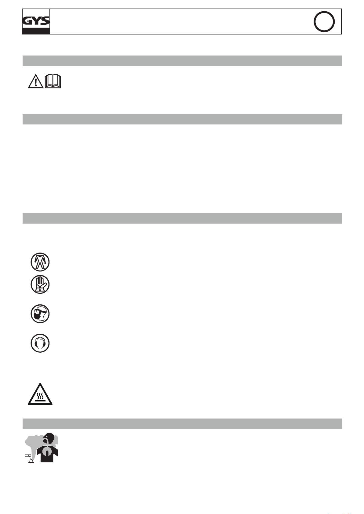
MODIFICATION DES PARAMÈTRES D’USINE (FIG-5)
L’appareil contrôle la vitesse d’accostage, le burn back et le post gaz. Ces paramètres sont réglés en usine, il est tout de fois possible de les modier
directement sur la carte électronique. Attention : cette intervention doit être faite par un électricien qualié.
IMPORTANT : Veuillez débrancher l’appareil avant toute intervention.
P1 : Réglage de la vitesse d’accostage permet une approche plus douce an d’éviter les éclaboussures aux premiers
courts-circuits.
50%
usine
P2 : Réglage du Burn back. Cette fonction permet d’éviter au l de venir se coller au tube contact en n de cordon.
P3 : Réglage du Post gaz. Réglage du temps pendant lequel le gaz continu de protéger le bain de fusion à la n du
cordon.
PARAMÉTRAGE EXPERT (SELON NORME EN 1090)
An de satisfaire aux exigences de la norme EN 1090, il est possible d’étalonner la tension, le courant et la vitesse l de l’appareil. Attention : l’étalonnage doit se faire par GYS ou le distributeur s’il possède un service de maintenance qualié. Équipements nécessaires : Charge résistive (réf :
060135), tachymètre (réf : 053953), voltmètre et ampèremètre (réf : 053984).
1/ Étalonnage de la tension et du courant (FIG-5) :
Les potentiomètres P4 (tension) et P5 (courant) sont réglables directement sur la carte électronique.
2/ Étalonnage de la vitesse l (FIG-4) :
L’accès à ce mode se fait par appui long sur la touche (1) pendant 3 sec. Ensuite, appuyer 3 fois sur la touche 1 an que l’afcheur indique « Fc3 ».
Vous pouvez maintenant étalonner votre vitesse l à +/- 10% par pas de 1% grâce aux touches (5) et (7). Pour sortir du mode, appuyer sur la touche
(1), l’afcheur indique « END ».
MODE CACHÉ (FIG-4)
Le mode caché permet d’atteindre les fonctions suivantes :
• le mode gougeage (Magys 500 GR / 500 WS) «Fc0»
• sélection du potentiomètre de vitesse l (uniquement pour le Magys 400 GR / 500 GR / 500 WS) «Fc1»
• autorisation/interdiction des matériaux «Fc2»
• étalonnage de la vitesse l (voir ci-dessus : paramétrages expert) «Fc3»
L’accès à ce mode se fait par appui maintenu sur la touche (1) pendant 3 sec. L’afcheur indique « Fc0 » , « OFF ». Appuyer de nouveau sur la touche
(1) pour entrer dans le mode Gougeage.
Mode gougeage : (Magys 500 GR / 500 WS) (Fc0)
L’afcheur du haut indique « Arc », « Air » et l’afcheur du bas indique « OFF ».
Pour activer le générateur de courant, appuyer sur la touche 5. L’afcheur indique alors « Arc », « Air », « On ».
ATTENTION : une fois le générateur de courant activé, la puissance en sortie d’appareil est disponible. Ne pas poser la torche au sol, en contact avec
un matériau métallique, utiliser des équipements de protections, …
Pour désactiver le générateur de courant appuyer sur la touche 5. Pour sortir du mode gougeage, il faut appuyer sur la touche 1. Cette sortie implique
une sortie du mode caché, l’afcheur indique « END ».
Procédure du gougeage :
- Mettre le commutateur à pleine puissance,
- ouvrir le robinet d’air,
- le contact entre l’électrode et la pièce provoque un court-circuit. Un bain de fusion est immédiatement produit et l’air canalisé par la torche projette
le métal en fusion du bain.
- l’avance du travail se fait en poussant, à l’inverse du MMA.
Pour une utilisation optimale il faut toujours laisser 100 – 150 mm entre le bout de l’électrode et la pince de gougeage.
La torche se connecte au générateur à l’arrière du produit, pôle + pour des électrodes acier, inox. Pour des électrodes en cuivre se connecter à
n’importe quel pôle. Pour une électrode Nickel se connecter au pôle -. La pince de masse se branche de la même manière que pour le soudage.
Il est important de respecter les indications notées sur les boîtes d’électrodes utilisées.
Cette manipulation requiert un EPI obligatoire !
10
Page 11
MAGYS 400-4 / 400 GR / 500 GR / 500 WS
FR
Sélection du potentiomètre de vitesse l (Magys 400 GR / 500 GR / 500 WS) : (Fc1)
Le réglage de la vitesse l peut se faire soit avec le potentiomètre du dévidoir, soit avec celui du
générateur. Les 2 ne peuvent pas être actifs en même temps.
Pour entrer dans le mode « Sélection du potentiomètre de vitesse l » appuyer 3 sec sur la touche
(1) et à nouveau sur cette touche. L’afcheur du haut indique « Fc1 » et l’afcheur du bas indique:
- « Out » pour le potentiomètre du dévidoir
- « In » pour le potentiomètre du générateur
Pour passer de Out à In, il suft d’appuyer sur la touche (5) dont les voyants clignotent. En appuyant
sur la touche (1) vous sortirez de cette fonction et passerez à la fonction « Autorisation/Interdiction
des matériaux »
FC1 s’affiche
In / Out
s’affiche
(1) 3 sec
(5) Permet de
sélectionner le
potentiomètre
Autorisation/interdiction des matériaux : (Fc2)
Il est possible d’autoriser ou non l’utilisation des 3 choix de matériaux (Fe CO², FeCrNi ArCO², Aluminium). Pour entrer dans ce mode il suft d’entrer
dans le mode caché et d’appuyer 2 fois sur la touche 1. L’afcheur indique « Fc2 ». An de choisir votre combinaison de matériaux (8 possibilités), il
suft d’appuyer sur la touche 5 jusqu’à obtenir ce que vous souhaitez. La position « Manual » ne peut être désactivée.
Pour sortir du mode caché appuyer sur la touche 1, l’afcheur indique « END ».
RISQUE DE BLESSURE LIÉ AUX COMPOSANTS MOBILES
Les dévidoirs sont pourvus de composants mobiles qui peuvent happer les mains, les cheveux, les vêtements ou les outils et
entraîner par conséquent des blessures !
• Ne pas porter la main aux composants pivotants ou mobiles ou encore aux pièces d’entraînement!
• Veiller à ce que les couvercles du carter ou couvercles de protection restent bien fermés pendant le fonctionnement !
• Ne pas porter de gants lors de l’enlement du l d’apport et du changement de la bobine du l d’apport.
ANOMALIES, CAUSES, REMÈDES
SYMPTÔMES CAUSES REMÈDES
Le débit du l de soudage n’est pas constant.
Le moteur de dévidage ne fonctionne pas.
Mauvais dévidage du l.
Pas de courant de soudage.
Le l bouchonne après les galets.
Le cordon de soudage est poreux.
Des grattons obstruent l’orice.
Le l patine dans les galets.
Un des galets patine Vérier le serrage de la vis du galet.
Frein de la bobine ou galet trop serré. Desserrer le frein et les galets
Problème d’alimentation
Gaine guide l sale ou endommagée. Nettoyer ou remplacer.
Frein de la bobine trop serré. Desserrer le frein.
Mauvais branchement de la prise secteur.
Mauvaise connexion de masse.
Contacteur de puissance inopérant. Contrôler la gâchette de la torche.
Gaine guide l écrasée. Vérier la gaine et corps de torche.
Blocage du l dans la torche. Remplacer ou nettoyer.
Pas de tube capillaire. Vérier la présence du tube capillaire.
Vitesse du l trop importante. Réduire la vitesse de l
Le débit de gaz est insufsant.
Bouteille de gaz vide. La remplacer.
Qualité du gaz non satisfaisante. Le remplacer.
Circulation d’air ou inuence du vent.
Buse gaz trop encrassée. Nettoyer la buse gaz ou la remplacer.
Mauvaise qualité du l. Utiliser un l adapté au soudage MIG-MAG.
État de la surface à souder de mauvaise qualité
(rouille, etc…)
Nettoyer le tube contact ou le changer et remettre du produit anti-adhésion.
- Contrôler la pression des galets ou les remplacer.
- Diamètre du l non conforme au galet.
-Gaine guide l dans la torche non conforme.
Vérier que le bouton de mise en service est
sur la position marche.
Voir le branchement de la prise et regarder si la
prise est bien alimentée avec 3 phases.
Contrôler le câble de masse (connexion et état
de la pince).
Plage de réglage de 15 à 25 L / min.
Nettoyer le métal de base.
Empêcher les courants d’air, protéger la zone
de soudage.
Nettoyer la pièce avant de souder
11
Page 12

MAGYS 400-4 / 400 GR / 500 GR / 500 WS
FR
Particules d’étincelage
très importantes.
Pas de gaz en sortie de torche Mauvaise connexion du gaz
À la mise sous tension :
l’afcheur (9) indique « Err » et l’afcheur (10)
indique « 002 ».
À la mise sous tension :
l’afcheur (9) indique « Err » et l’afcheur (10)
indique « 001 ».
Le gaz n’est pas connecté
Tension d’arc trop basse ou trop haute. Voir paramètres de soudage.
Mauvaise prise de masse.
Au moins une des 3 touches du clavier
enfoncée.
La gâchette de la torche est enfoncée. La gâchette doit être relâchée.
Vérier que le gaz est connecté à l’entrée géné-
rateur.
Contrôler et positionner la pince de masse au
plus proche de la zone à souder
Vérier le branchement des entrées de gaz
Vérier que l’électrovanne fonctionne
est
Les 3 touches
doivent être relâchées.
CONDITIONS DE GARANTIE FRANCE
La garantie couvre tous défauts ou vices de fabrication pendant 2 ans, à compter de la date d’achat (pièces et main d’oeuvre).
La garantie ne couvre pas :
• Toutes autres avaries dues au transport.
• L’usure normale des pièces (Ex. : câbles, pinces, etc.).
• Les incidents dus à un mauvais usage (erreur d’alimentation, chute, démontage).
• Les pannes liées à l’environnement (pollution, rouille, poussière).
En cas de panne, retourner l’appareil à votre distributeur, en y joignant :
- un justicatif d’achat daté (ticket de sortie de caisse, facture….)
- une note explicative de la panne.
12
Page 13
MAGYS 400-4 / 400 GR / 500 GR / 500 WS
EN
WARNING - SAFETY RULES
GENERAL INSTRUCTIONS
Read and understand the following safety recommendations before using or servicing the unit.
Any change or servicing that is not specied in the instruction manual must not be undertaken.
The manufacturer is not liable for any injury or damage caused due to non-compliance with the instructions featured in this manual .
In the event of problems or uncertainties, please consult a qualied person to handle the installation properly.
ENVIRONMENT
This equipment must only be used for welding operations in accordance with the limits indicated on the descriptive panel and/or in the user manual.
The operator must respect the safety precautions that apply to this type of welding. In case of inedaquate or unsafe use, the manufacturer cannot
be held liable for damage or injury.
This equipment must be used and stored in a place protected from dust, acid or any other corrosive agent. Operate the machine in an open, or
well-ventilated area.
Operating temperature:
Use between -10 and +40°C (+14 and +104°F).
Store between -20 and +55°C (-4 and 131°F).
Air humidity:
Lower or equal to 50% at 40°C (104°F).
Lower or equal to 90% at 20°C (68°F).
Altitude:
Up to 1000 meters above sea level (3280 feet).
PROTECTION OF THE INDIVIDUALS
Arc welding can be dangerous and can cause serious and even fatal injuries.
Welding exposes the user to dangerous heat, arc rays, electromagnetic elds, noise, gas fumes, and electrical shocks. People wearing pacemakers
are advised to consult with their doctor before using this device.
To protect oneself as well as the other, ensure the following safety precautions are taken:
In order to protect you from burns and radiations, wear clothing without cuffs. These clothes must be insulated, dry, reproof and
in good condition, and cover the whole body.
Wear protective gloves which guarantee electrical and thermal insulation.
Use sufcient welding protective gear for the whole body: hood, gloves, jacket, trousers... (varies depending on the application/
operation). Protect the eyes during cleaning operations. Do not operate whilst wearing contact lenses.
It may be necessary to install reproof welding curtains to protect the area against arc rays, weld spatters and sparks.
Inform the people around the working area to never look at the arc nor the molten metal, and to wear protective clothes.
Ensure ear protection is worn by the operator if the work exceeds the authorised noise limit (the same applies to any person in the
welding area).
Stay away from moving parts (e.g. engine, fan...) with hands, hair, clothes etc.
Never remove the safety covers from the cooling unit when the machine is plugged in - The manufacturer is not responsible for any
accident or injury that happens as a result of not following these safety precautions.
The pieces that have just been welded are hot and may cause burns when manipulated. During maintenance work on the torch or
the electrode holder, you should make sure it’s cold enough and wait at least 10 minutes before any intervention. The cooling unit
must be on when using a water cooled torch in order to ensure that the liquid does not cause any burns.
ALWAYS ensure the working area is left as safe and secure as possible to prevent damage or accidents.
WELDING FUMES AND GAS
The fumes, gases and dust produced during welding are hazardous. It is mandatory to ensure adequate ventilation and/or
extraction to keep fumes and gases away from the work area. An air fed helmet is recommended in cases of insufcient air supply
in the workplace.
Check that the air intake is in compliance with safety standards.
Care must be taken when welding in small areas, and the operator will need supervision from a safe distance. Welding certain pieces of metal
containing lead, cadmium, zinc, mercury or beryllium can be extremely toxic. The user will also need to degrease the workpiece before welding.
Gas cylinders must be stored in an open or ventilated area. The cylinders must be in a vertical position secured to a support or trolley.
Do not weld in areas where grease or paint are stored.
13
Page 14
MAGYS 400-4 / 400 GR / 500 GR / 500 WS
EN
FIRE AND EXPLOSION RISKS
Protect the entire welding area. Compressed gas containers and other inammable material must be moved to a minimum safe
distance of 11 meters. A re extinguisher must be readily available.
Be careful of spatter and sparks, even through cracks. It can be the source of a re or an explosion.
Keep people, ammable objects and containers under pressure at a safe distance.
Welding of sealed containers or closed pipes should not be undertaken, and if opened, the operator must remove any inammable or explosive
materials (oil, petrol, gas...).
Grinding operations should not be directed towards the device itself, the power supply or any ammable materials.
GAS BOTTLE
Gas leaking from the cylinder can lead to suffocation if present in high concentrations around the work area.
Transport must be done safely: Cylinders closed and product off. Always keep cylinders in an upright position securely chained to
a xed support or trolley. Close the bottle after any welding operation. Be wary of temperature changes or exposure to sunlight.
Close the bottle after any welding operation. Be wary of temperature changes or exposure to sunlight.
Cylinders should be located away from areas where they may be struck or subjected to physical damage.
Always keep gas bottles at a safe distance from arc welding or cutting operations, and any source of heat, sparks or ames.
Be careful when opening the valve on the gas bottle, it is necessary to remove the tip of the valve and make sure the gas meets your welding
requirements.
ELECTRIC SAFETY
The machine must be connected to an earthed electrical supply. Use the recommended fuse size.
An electrical discharge can directly or indirectly cause serious or deadly accidents .
Do not touch any live part of the machine (inside or outside) when it is plugged in (Torches, earth cable, cables, electrodes) because they are
connected to the welding circuit.
Before opening the device, it is imperative to disconnect it from the mains and wait 2 minutes, so that all the capacitors are discharged.
Do not touch the torch or electrode holder and earth clamp at the same time.
Damaged cables and torches must be changed by a qualied and skilled professional. Make sure that the cable cross section is adequate with the
usage (extensions and welding cables). Always wear dry clothes in good condition, in order to be insulated from the electrical circuit. Wear insulating
shoes, regardless of the environment in which you work in.
EMC CLASSIFICATION
These Class A devices are not intended to be used on a residential site where the electric current is supplied by the public
network, with a low voltage power supply. There may be potential difculties in ensuring electromagnetic compatibility on these
sites, because of the interferences, as well as radio frequencies.
This equipment complies with IEC 61000-3-12, provided that the power of the short-circuit Ssc is equal to or greater than 3.9
MVA at the interface between the machine and the mains power network. It is the responsibility of the installer or user of the
equipment to ensure if necessary by consulting the operator of the mains electricity, that the equipment is only connected to a
power supply where the power of short-circuit ssc is equal to or greater than 3.9 MVA.
This equipment complies with the IEC 61000-3-11 standard.
ELECTROMAGNETIC INTERFERENCES
The electric currents owing through a conductor cause electrical and magnetic elds (EMF). The welding current generates an EMF
eld around the welding circuit and the welding equipment.
The EMF elds may disrupt some medical implants, such as pacemakers. Protection measures should be taken for people wearing medical implants.
For example, access restrictions for passers-by or an individual risk evaluation for the welders.
All welders should take the following precautions in order to minimise exposure to the electromagnetic elds (EMF) generated by the welding circuit::
• position the welding cables together – if possible, attach them;
• keep your head and torso as far as possible from the welding circuit;
• never enroll the cables around your body;
• never position your body between the welding cables. Hold both welding cables on the same side of your body;
• connect the earth clamp as close as possible to the area being welded;
• do not work too close to, do not lean and do not sit on the welding machine
• do not weld when you’re carrying the welding machine or its wire feeder.
14
Page 15
MAGYS 400-4 / 400 GR / 500 GR / 500 WS
People wearing pacemakers are advised to consult their doctor before using this device.
Exposure to electromagnetic elds while welding may have other health effects which are not yet known.
EN
RECOMMANDATIONS TO ASSES THE AREA AND WELDING INSTALLATION
Overview
The user is responsible for installing and using the arc welding equipment in accordance with the manufacturer’s instructions. If electromagnetic
disturbances are detected, it is the responsibility of the user of the arc welding equipment to resolve the situation with the manufacturer’s technical
assistance. In some cases, this remedial action may be as simple as earthing the welding circuit. In other cases, it may be necessary to construct an
electromagnetic shield around the welding power source and around the entire piece by tting input lters. In all cases, electromagnetic interferences
must be reduced until they are no longer bothersome.
Welding area assessment
Before installing the machine, the user must evaluate the possible electromagnetic problems that may arise in the area where the installation is
planned.
. In particular, it should consider the following:
a) the presence of other power cables (power supply cables, telephone cables, command cable, etc...)above, below and on the sides of the arc
welding machine.
b) television transmitters and receivers ;
c) computers and other hardware;
d) critical safety equipment such as industrial machine protections;
e) the health and safety of the people in the area such as people with pacemakers or hearing aids;
f) calibration and measuring equipment
g)The isolation of the equipment from other machinery.
The user will have to make sure that the devices and equipments that are in the same room are compatible with each other. This may require extra
precautions;
h) make sure of the exact hour when the welding and/or other operations will take place.
The surface of the area to be considered around the device depends on the the building’s structure and other activities that take place there. The area
taken in consideration can be larger than the limits determined by the companies.
Welding area assessment
Besides the welding area, the assessment of the arc welding systems intallation itself can be used to identify and resolve cases of disturbances. The
assessment of emissions must include in situ measurements as specied in Article 10 of CISPR 11: 2009. In situ measurements can also be used to
conrm the effectiveness of mitigation measures.
RECOMMENDATION ON METHODS OF ELECTROMAGNETIC EMISSIONS REDUCTION
a. National power grid: The arc welding machine must be connected to the national power grid in accordance with the manufacturer’s
recommendation. If interferences occur, it may be necessary to take additional preventive measures such as the ltering of the power suplly network.
Consideration should be given to shielding the power supply cable in a metal conduit. It is necessary to ensure the shielding’s electrical continuity
along the cable’s entire length. The shielding should be connected to the welding current’s source to ensure good electrical contact between the
conduct and the casing of the welding current source.
b. Maintenance of the arc welding equipment: The arc welding machine should be be submitted to a routine maintenance check according to
the manufacturer’s recommendations. All accesses, service doors and covers should be closed and properly locked when the arc welding equipment
is on.. The arc welding equipment must not be modied in any way, except for the changes and settings outlined in the manufacturer’s instructions.
The spark gap of the arc start and arc stabilization devices must be adjusted and maintained according to the manufacturer’s recommendations.
c. Welding cables: Cables must be as short as possible, close to each other and close to the ground, if not on the ground.
d. Electrical bonding : consideration shoud be given to bonding all metal objects in the surrounding area. However, metal objects connected to
the workpiece increase the riskof electric shock if the operator touches both these metal elements and the electrode. It is necessary to insulate the
operator from such metal objects.
e. Earthing of the welded part : When the part is not earthed - due to electrical safety reasons or because of its size and its location (which is the
case with ship hulls or metallic building structures), the earthing of the part can, in some cases but not systematically, reduce emissions It is preferable
to avoid the earthing of parts that could increase the risk of injury to the users or damage other electrical equipment. If necessary, it is appropriate
that the earthing of the part is done directly, but in some countries that do not allow such a direct connection, it is appropriate that the connection is
made with a capacitor selected according to national regulations.
f. Protection and plating : The selective protection and plating of other cables and devices in the area can reduce perturbation issues. The
protection of the entire welding area can be considered for specic situations.
TRANSPORT AND TRANSIT OF THE WELDING MACHINE
Do not use the cables or torch to move the machine. The welding equipment must be moved in an upright position.
Do not place/carry the unit over people or objects.
Never lift the machine while there is a gas cylinder on the support shelf. A clear path is available when moving the item.
The removal of the wire reel from the machine is recommended before undertaking any lifting operation.
The machine is tted with handle(s) to facilitate transportation. Be careful not to underestimate the machine’s weight. The handle(s) cannot be used
for slinging.
Stray welding currents/voltages may destroy earth conductors, damage electrical equipment or cause components to warm up which may cause a re.
• All welding connections must be rmly secured, check regularly !
• Check that the metal piece xation is strong and without any electrical problems !
• Attach or hang all the electrically conductive elements, such as the trolley and slinging equipment, in order to insulate them
• Do not place any electrical equipment, such as drills or grinders, on top of the welding machine without insulating them !
• Always place welding torches or electrodes holders on an insulated surface when they’re not in use !
15
Page 16
MAGYS 400-4 / 400 GR / 500 GR / 500 WS
EN
EQUIPMENT INSTALLATION
• Put the machine on the oor (maximum incline of 10°.)
• Ensure the work area has sufcient ventillation for welding, and that there is easy access to the control panel.
• The machine must be placed in a sheltered area away from rain or direct sunlight.
• The machine must not be used in an area with conductive metal dusts.
• The machine protection level is IP23, which means :
- Protection against acess to dangerous parts from solid bodies of a ≥12.5mm diameter and,
- Protection against the rain inclined at 60% towards the vertical.
These devices can be used outside in accordance with the IP23 protection index.
• Do not use the machine at temperatures > 40°C.
The power cables, extensions and welding cables must be fully uncoiled to prevent overheating.
The manufacturer does not incur any responsability regarding damages to both objects and persons that result from an incorrect
and/or dangerous use of the machine .
MAINTENANCE / RECOMMENDATIONS
• Maintenance should only be carried out by a qualied person. Annual maintenance is recommended.
• Ensure the machine is unplugged from the mains, and wait for two minutes before carrying out maintenance work. DANGER
High Voltage and Currents inside the machine.
• Remove the casing 2 or 3 times a year to remove any excess dust. Take this opportunity to have the electrical connections checked by a qualied
person, with an insulated tool.
• Regularly check the condition of the power supply cable. If the power cable is damaged, it must be replaced by the manufacturer, its after sales
service or an equally qualied person.
• Ensure the ventilation holes of the device are not blocked to allow adequate air circulation.
• Do not use this equipment to thaw pipes, to charge batteries, or to start any engine.
INSTALLATION – PRODUCT OPERATION
Only qualied personnel authorised by the manufacturer should perform the installation of the welding equipment. During the installation, the
operator must ensure that the machine is disconnected from the mains.
DESCRIPTION
Magys are «synergic» semi-automatic welding units on wheels, ventilated for welding (MIG or MAG). They operate on a three-phase 400 V power
supply.
To operate, the MAGYS:
• 400 GR must be used with the external wire feeder WS-4R (ref. 034723) or W5S-4L (ref 032835) and an interconnect cable.
• 500 GR must be used with the external wire feeder WS-4R (ref. 034723) or W5S-4L (ref 032835) and an interconnect cable.
• 500 WS must be used with the external wire feeder WS-4L (ref. 033573) or W5S-4L (ref 032835) and an interconnect cable.
POWER SUPPLY
This machine is tted with a 32 A socket type EN 60309-1 which must only be used on a three-phase 400 V (50 - 60 Hz) power supply tted with four
wires and one earthed neutral.
The absorbed effective current (I1eff) is displayed on the machine, for optimal use. Check that the power supply and its protection (fuse and/or
circuit breaker) are compatible with the current needed by the machine. In some countries, it may be necessary to change the plug to allow the use
at maximum settings.
• The machine is designed to work on a 400V +/- 15% power supply. • It switches to protection mode if the power supply voltage is below 330V
RMS or over 490V RMS.
• The start is done via an on / off switch (1 - FIG 1) set to I, and the stop is done by switching it to 0. Warning! Never disconnect the power supply
while the machine is charging.
• Fan operation: The MAGYS 400-4/400 GR and 500 GR features an intelligent cooling fan system in order to minimise machine noise. The ventila-
tion remains activated for 10 minutes and then stops automatically. If the user changes the mode by pressing the dedicated key (1 - FIG 4) it will
immediately stop the cooling. It will be switched on again at the next welding bead. Same operation for the MAGYS 500 WS and its cooling system
(cooling unit and fan).
CONNECTION TO A GENERATOR
The machine can work with generators as long as the auxiliary power meets the following requirements:
- The voltage must be AC, with a 400V ±15% RMS value and a peak voltage below 700V,
- The frequency must be between 50 and 60 Hz.
It is imperative to check these requirements, as many generators generate high voltage peaks that can damage these machines.
USE OF EXTENSION LEADS
All extension leads must have an adequate size and section, relative to the machine’s voltage.
Use an extension lead that complies with national safety regulations.
Current input Extension lead section (<45m)
400 V 6 mm²
16
Page 17
MAGYS 400-4 / 400 GR / 500 GR / 500 WS
EN
DEVICE PRESENTATION
Put the rubber mat (only for the Magys 400-4) and the four ring eyes (with their lock washers). The gas bottle needs to be fastened with 2 chains in
the holes at the back of the machine. Attention: Fasten correctly the bottle. You have also holes to pass a strap on (not included).
1- On – Off switch 8- Fastening chains for bottles
Power settings – 2 switches with 9 positions
2-
to adjust the welding voltage output
3- Control panel – Welding settings 10-
4- European standard torch connection 11- Water inlet and outlet (Magys 500 WS)
5- Power cable (5 m) 12- 5.5 L tank (Magys 500 WS)
6- Earth cable 13- Chain xing slot
7- Gas bottle support (max 1 bottle of 10 m
3
)
9- Reel support Ø 200/300 mm.
Gas connector (For the Magys 500 WS, the gas hose needs to be
connected to the owmeter of the bottle).
SEMI-AUTOMATIC WELDING FOR STEEL / STAINLESS STEEL (MAG MODE) (FIG. 2-A)
The MAGYS units are equipped originally to work on 1mm steel wire (original drive rollers Ø 1/1.2 steel/stainless steel).
Make sure that drive rollers, liner and contact tube are adapted to your wire diameter.
For Steel or Stainless Steel, you will need to use specic gas - Argon + CO2 (Ar + CO2). The proportion of CO2 will vary depending on usage. The
gas ow for steel is between 15 and 25L / min depending on the environment and experience of the welder.
For wires with a diameter > 1.6 mm, it is recommended to remove the capillary tube.
SEMI-AUTOMATIC WELDING FOR ALUMINIUM (MIG MODE) (FIG. 2-B)
This welding unit can weld aluminium wires from 1mm.
To weld aluminium, neutral gas “pure Argon” (AR) is required. When choosing gas, ask a gas distributor for advice. The gas ow in aluminium should
be between 20 and 25 L / min depending on the environment and experience of the welder.
Things to note when welding with Aluminium
- Set the pressure of the rollers to a minimum so as not to crush the wire
- Remove the capillary tube before connecting the aluminium torch
- When welding aluminium use a special aluminium torch with Teon sheath to reduce friction.
Do not cut the sheath near the connector! It is used to guide the wire from the rollers.
(See diagram (16))
- Contact Tip: Use the specic Aluminium contact tip corresponding to the diameter of the wire.
- Drive rollers: Use specic drive rollers to weld with aluminium wire.
REEL AND TORCH ASSEMBLY (FIG. 3)
• Position the reel on to the support taking care of the pin (1). To use with 5kg (Ø200mm) wire reels requires use of reel adaptor (ref. 042889).
• Adjust the reel break (2) to avoid the reel movement tangling the wire when welding stops. Then tighten the plastic screw (3) rmly.
• For the rst use :
- Release the xing screw of the wire guide (5)
- Place the rollers, and tighten the screws (6).
- Place the wire guide (7) as close as possible to the roller but without touching it, then tighten the xing screw.
• To select the adjustment of the drive rollers (8), bend the wire where it comes out of the nozzle to stop it, and then start the motor. Tighten the
knob whilst pressing the trigger until the wire starts to move. The setting is correct when the guide roller slides over the wire, even when it is blocked
at the end of the torch.
NOTE: When the trigger is pulled and without any contact detected within 4s, the MAGYS will automatically switch to the ‘fast forward’ mode until
the trigger is released. There is no gas during this operation.
WARNING: The ‘fast forward’ mode use current in the wire; avoid any contact with any metallic part around.
GAS COUPLING
Fit the regulator/owmeter to the gas bottle, and then t the gas pipe to the connector (see (10), FIG-2 for MAGYS 400-4). To avoid gas leaks, use
the collars provided in the accessories box.
LIQUID COOLING (MAGYS 500 WS) (FIG-2) & THERMAL PROTECTION
Connect the red and blue wire of the connecting harness from the generator (11) to the separate wire feeder (see WS-4L/W5S-4L user manual)
Fill the tank (12) up to its maximum (5.5L). The cooling liquid recommended by GYS (ref. 052246), must be used. The use of any other cooling
liquid, and especially the standard automobile liquid, can lead by electrolysis effect, to the accumulation of dumps in the cooling system, damaging
it and even more by blocking the circuit.
Any damage caused to the machine by the use of another cooling liquid will not be taken under warranty.
The MAGYS 500 WS is not recommended to be used by an air cooled torch.
If anyway you want to use an air cooled torch, a by-pass is supplied with the unit. Connect it between the red and blue cables. If
you don’t respect this rule, the pump will be damaged, and the repair will not be taken under warranty.
MAGYS 500 WS: NEVER USE YOUR UNIT WITHOUT COOLING LIQUID
when the pump is working. Ensure liquid is at least minimum level (gauge at back of machine)
Failure to adhere to this may result in irreparable damage to the cooling system, and machine.
17
Page 18
MAGYS 400-4 / 400 GR / 500 GR / 500 WS
• Always respect the basic rules of welding.
• Do not block/cover the ventilation holes of the machine.
• Leave the device plugged in after welding to allow proper cooling down.
• Thermal protection: The LED(8) switches on when the unit is on safety mode. The cooling time (forced ventilation) is by cycle of 10 minutes for the
400-4 and 20 minutes (forced ventilation + pump) for the MAGYS 400 GR/500 GR/500 WS depending on the external temperature.
• Ventilation: the fan is only active during the welding and the cooling cycles.
EN
CONTROL PANEL (FIG-4)
Welding mode selection / test:
- 2T: two-stage welding / 4T: four-stage welding.
- SPOT: Spot welding with adjustable spot diameter
- Delay: intermittent welding modes for an optimised operating
procedure
2 modes to make easier the setting up of the welding unit: «
Manual » or « Synergic ».
1
- Test function: The LED switches on when you push the button
(1). Read chapter «Welding unit settings»
Access to the hidden mode and Expert mode setting
(see next page)
Voltage display: By pulling the trigger (The LED
9
indicates that your torch is on) the voltage will be displayed
according to the parameters selected.
Power adjustment switch: 20 positions for the Magys 400-
12
4, 400 GR and 30 for the 500 GR / 500 WS.
SPOT / DELAY potentiometer: To adjust the welding time of a
3
point, the size of the point and the time between each point.
Arc dynamics potentiometer: To adjust automatically or
4
manually the arc dynamics.
Metal selection and manual mode: Read chapter «Welding
5
unit settings»
Mode « Synergic »: Read chapter «Welding unit settings»
6
Wire diameter: Select the wire diameter used.
7
Thermal protection LED: Read chapter «Thermal protection».
8
Wire speed setting: Potentiometer to adjust the wire speed.
The speed can vary from 1 to 24 m/minute.
Note for the MAGYS 400 GR/500 GR/500 WS: It is possible to
select either the potentiometer of the separate wire feeder or
2
the generator.
See chapter «wire speed potentiometer» and the sticker inside
the wire feeder
Welding current display 10: indicates the amperage (LED «
A ») or the thickness 11 recommended according to the power
selected (read « test » function in the chapter « Welding unit
10
settings »).
Note: « NOP » on the display indicates that the welding cur-
11
rent selected is superior to the one recommended taking into
account the parameters (type and diameter of the wire).
WELDING UNIT SETINGS (FIG-4)
« SYNERGIC » MODE
This function automatically controls the wire speed. There is no need to set the wire speed manually.
- Position the potentiometer (2) in the middle of the « Optimal synergic » zone
- Select: Wire type (5), wire diameter (7), power mode (with the 2 power switches on the front (12)).
From the settings chosen, the unit determines the optimum wire speed and is ready to weld. It is also possible to manually adjust the wire speed (+
or –) if necessary using the potentiometer (2). The last welding conguration is saved in the memory automatically (wire diameter, wire type, mode).
« Test » function
NOTE: If the gas, the wire diameter, and the metal used are different from the ones selected in the synergic mode, you will need to switch to the
manual mode to set up the welding unit.
Only in the synergic mode, I twill indicate you the thickness you can weld with the parameters selected without using
any gas or wire. These values are calculated on the basis of a welding on the at surface. Attention: you have current
in the torch, so avoid any contact with any metallic part.
«MANUAL » MODE
To set your device, proceed as follows:
- Choose the welding voltage using the 2 power switches according to the thickness to weld.
- Adjust the wire speed using the potentiometer (12).
When in manual this function displays the wire speed setting on display (10).
MODIFICATION OF THE ORIGINAL PARAMETERS (FIG-4)
The device controls the arcing speed, the burn back and the post gaz. These parameters are set up in the factory, but it is possible to modify them
directly on the circuit board. Attention: this intervention must be done by a qualied electrician.
IMPORTANT : Make sure the product is not connected to the power supply before any intervention
18
Page 19
0%
100%
50%
(Factory
setting)
MAGYS 400-4 / 400 GR / 500 GR / 500 WS
P1: Set up the arcing speed to have a smooth start in order to avoid any spatter with the rst short circuit.
P2: Set up the Burn back to avoid the sticking of the wire on the contact tube.
P3: The setting up of the Post gas will regulate the time of gas used after the welding to protect it.
EN
EXPERT SETTING (ACCORDING TO STANDARD EN 1090)
In order to meet the EN 1090 standard, it is possible to calibrate the voltage, the current and the wire speed of this product. Warning: the calibration must be done by GYS or the distributor where they have a qualied maintenance department using the correct equipment: resistive load (ref:
060135), tachometer (ref: 053953), voltmeter and ammeter (ref: 053984).
1/ Calibration of voltage and current (FIG-5):
The potentiometers P4 (voltage) and P5 (current) are adjustable directly on the electronic board.
2/ Calibration of the wire speed (FIG-4):
To access this mode, you need to press key (1) for 3 seconds. Then, press key (1) 3 times to display «Fc3». Now, you can calibrate your wire speed
to more or less 10% by step of 1% with keys (5) and (7). To exit this mode, press key (1), the display shows «END».
HIDDEN MODE PARAMETERS (FIG-4)
The hidden mode allows you to set the following parameters:
- Gouging mode (only for Magys 500 GR / 500 WS) «Fc0»
- Selection of the wire speed potentiometer (only for Magys 400 GR / 500 GR / 500 WS) «Fc1»
- Metal Selection «Fc2»
- Calibration of the wire speed (see above: expert settings) «Fc3»
To enter this mode, press and hold button 1 for 3 sec. The machine will display « Fc0 », « OFF ». Press button 1 again to enter Gouging mode.
Gouging mode: (only for Magys 500 GR / 500 WS) (Fc0)
The top screen will display « Arc », « Air » and the bottom screen « OFF ».
To activate the power generator, push button 5. The display will show « Arc », « Air », « On ».
ATTENTION: once the power generator is activated, the output current is available on the unit. Do not put the torch on the oor or in contact with
any metallic part. Always wear protective clothing.
To deactivate the power generator push button 5. To leave Gouging mode and hidden mode, push button 1 and the screen will display « END ».
Gouging process:
- Turn the voltage switch to maximum,
- Open the cylinder valve or compressed air network,
- Contact between the electrode and the metal piece will create a circuit. The intense heat will melt the workpiece and air will pass through the arc
quickly enough to blow the molten material away.
- Conversely to the MMA process, the work is done by pushing the arc.
The visible length of the electrode must between 100 and 150 mm.
The torch is connected to the back of the generator, on the + terminal for steel and stainless steel electrodes. For copper electrodes you can use any
terminal. For Nickel electrodes connect the electrode holder to the – terminal. The earth clamp is connected to the other terminal.
Always follow the instructions as indicated on the electrode packaging.
Protective clothing should always be worn when gouging!
Selection of the wire speed: (only for the Magys 400 GR/500 GR/500 WS) (Fc1)
Wire speed can be adjusted using wire feeder potentiometer or generator potentiometer. Only one
potentiometer can be active at a time.
Fc1 is displayed
In / Out is
On this type of equipment with separate wire feeder, 2 wire speed potentiometers are available.
You can choose to use between both but they can’t be activated at the same time.
To enter into « Selection of the wire speed potentiometer » mode push button 1 for 3 seconds
and then press the same button again. The top screen will display « Fc1 » and the bottom one:
- « Out » for the separate wire feeder potentiometer
- « In » for the generator potentiometer.
To choose between Out and In, press button 5. Press button 1 to leave this mode and enter
another mode.
displayed
(1) 3 s
(5) Potentiometer
selection
Metal selection (Fc2)
This mode will allow you to select or de-select a specied combination of 3 types of metal (Fe CO², FeCrNi ArCO², Aluminium). To enter this mode,
follow the instruction to enter hidden mode and press button 1 twice. The screen will display « Fc2 ». In order to choose the combination of metal (8
selections available), press button 5 until you reach the combination required. The « Manual » position can’t be deactivated.
To leave the hidden mode press button 1, the screen will display« END ».
19
Page 20
MAGYS 400-4 / 400 GR / 500 GR / 500 WS
RISK OF INJURY DUE TO MOVING PARTS
The wire feeders contain moving parts that may catch hands, hair, clothes or tools and lead to injuries!
• Do not touch rotating / moving / feeding parts of the machine!
• Make sure that all panels remain closed when in use!
• Do not wear gloves when setting up the wire and changing the wire reel.
TROUBLESHOOTING
SYMPTOMS POSSIBLE CAUSES REMEDIES
Debris is blocking up the opening.
The welding wire speed is not constant.
The wire-feeder motor doesn’t operate.
Bad wire feed.
No welding current
The wire jams (after the rollers)
The welding bead is porous
The arc produces a lot of sparks
No gas ow at the end of the torch. Bad gas connection.
When powering on:
The display (9) shows « Err » and the display
(10) shows « 002 ».
When powering on:
The display (9) shows « Err » and the display
(10) shows « 001 ».
The wire skids in the rollers.
The rollers slide over the wire Check and tighten the roller’s screws.
Reel or roller brake too tight. Adjust the brake and rollers.
Electrical supply problem.
Covering wire guide dirty or damaged. Clean or replace
Reel brake too tight Adjust the brake
Bad connection to the main supply.
Bad earth connection.
Torch trigger inoperative. Check the torch trigger / replace torch
Guide wire sheath crushed. Check the sheath and torch body.
Wire jammed in the torch Clean or replace.
No capillary tube. Check the presence of capillary tube.
Wire speed too fast Reduce the wire speed
The gas ow rate is not sufcient.
Gas bottle empty. Replace
Gas quality unsatisfactory. Replace
Air ow or wind inuence. Prevent drafts, protect welding area.
Gas nozzle dirty. Clean or replace the gas nozzle.
Poor quality wire. Use suitable WIRE for MIG-MAG welding.
Work-piece in bad condition. (rust, etc…) Clean the metal before welding.
Arc voltage too low or too high. See welding settings.
Bad earth connection.
Insufcient gas ow. Adjus the gas ow.
At least one of the 3 keys
The Torch’s trigger is pressed. The trigger must be released.
is pressed.
EN
Clean out the contact tip or change it and
replace the anti-adherence product.
Ref. 041806
• Check the roller pressure or replace it.
• Wire diameter incompatible with roller
• Covering wire guide in the torch incompatible.
Check that the power switch is in the "On"
position.
Check the mains connection and ensure the
supply is 400 V (3PH).
Check the earth cable (connection and clamp
condition).
Adjust ow range 15 to 25 L / min.
Clean the work-piece.
Check the earth cable (connection and clamp
condition)
Check that the gas pipe is plugged properly.
Check the solenoid valve.
The 3 keys
must be released.
WARRANTY
The warranty covers faulty workmanship for 2 years from the date of purchase (parts and labour).
The warranty does not cover:
• Transit damage.
• Normal wear of parts (eg. : cables, clamps, etc..).
• Damages due to misuse (power supply error, dropping of equipment, disassembling).
• Environment related failures (pollution, rust, dust).
In case of failure, return the unit to your distributor together with:
- The proof of purchase (receipt etc ...)
20
- A description of the fault reported
Page 21

MAGYS 400-4 / 400 GR / 500 GR / 500 WS
DE
SICHERHEITSANWEISUNGEN
ALLGEMEIN
Die Missachtung dieser Anweisungen und Hinweise kann zu schweren Personen- und Sachschäden
führen. Nehmen Sie keine Wartungarbeiten oder Veränderungen am Gerät vor, die nicht explizit in der
Anleitung gennant werden.
Der Hersteller haftet nicht für Verletzungen oder Schäden, die durch unsachgemäße Handhabung dieses Gerätes enstanden sind.
Bei Problemen oder Fragen zum korrekten Gebrauch dieses Gerätes, wenden Sie sich bitte an entsprechend qualiziertes und geschultes Fachpersonal.
UMGEBUNG
Dieses Gerät darf ausschließlich für Schweißarbeiten für die auf dem Siebdruck-Aufdruck bzw. dieser Anleitung angegebenen Materialanforderungen
(Material, Materialstärke, usw) verwendet werden. Es wurde allein für die sachgemäße Anwendung in Übereinstimmung mit konventionellen
Handelspraktiken und Sicherheitsvorschriften konzipiert. Der Hersteller ist nicht für Schäden bei fehlerhaften oder gefährlichen Verwendung nicht
verantwortlich.
Verwenden Sie das Gerät nicht in Räumen, in denen sich in der Luft metallische Staubpartikel benden, die Elektrizität leiten können. Achten Sie
sowohl beim Betrieb als auch bei der Lagerung des Gerätes auf eine Umgebung, die frei von Säuren, Gasen und anderen ätzenden Substanzen ist.
Achten Sie auf eine gute Belüftung und ausreichenden Schutz bzw. Ausstattung der Räumlichkeiten.
Betriebstemperatur:
zwischen -10 und +40°C (+14 und +104°F).
Lagertemperatur zwischen -20 und +55°C (-4 und 131°F).
Luftfeuchtigkeit:
Niedriger oder gleich 50% bis 40°C (104°F).
Niedriger oder gleich 90% bis 20°C (68°F).
Das Gerät ist bis in einer Höhe von 1.000m (über NN) einsetzbar.
SICHERHEITSHINWEISE
Lichtbogenschweißen kann gefährlich sein und zu schweren - unter Umständen auch tödlichen - Verletzungen führen.
Beim Lichtbogen ist der Anwender einer Vielzahl potentieller Risiken ausgesetzt: gefährliche Hitzequelle, Lichtbogenstrahlung, elektromagnetische
Störungen (Personen mit Herzschnittmacher oder Hörgerät sollten sich vor Arbeiten in der Nähe der Maschinen von einem Arzt beraten lassen),
elektrische Schläge, Schweißlärm und -rauch.
Schützen Sie daher sich selbst und andere. Beachten Sie unbedingt die folgenden Sicherheitshinweise:
Die Strahlung des Lichtbogens kann zu schweren Augenschäden und Hautverbrennungen führen. Die Haut muss durch geeignete,
trockene Schutzbekleidung (Schweißerhandschuhe, Lederschürze, Sicherheitsschuhe) geschützt werden.
Tragen Sie bitte elektrisch- und wärmeisolierende Schutzhandschuhe.
Tragen Sie bitte Schweißschutzkleidung und einen Schweißschutzhelm mit einer ausreichenden Schutzstufe (je nach Schweißart und
-strom). Schützen Sie Ihre Augen bei Reinigungsarbeiten. Kontaktlinsen sind ausdrücklich verboten!
Schirmen Sie den Schweißbereich bei enstprechenden Umgebungsbedingungen durch Schweißvorhänge ab, um Dritte vor
Lichtbogenstrahlung, Schweißspritzern, usw. zu schützen.
In der Nähe des Lichtbogens bendliche Personen müssen ebenfalls auf Gefahren hingewiesen werden und mit den nötigen Schutz
ausgerüstet werden.
Bei Gebrauch des Schweißgerätes ensteht sehr großer Lärm, der auf Dauer das Gehör schädigt. Tragen Sie daher im Dauereinsatz
ausreichend Gehörschutz und schützen Sie in der Nähe arbeitende Personen.
Achten Sie auf einen ausreichenden Abstand mit ungeschützten Hände, Haaren und Kleidungstücken zum Lüfter.
Entfernen Sie unter keinen Umständen das Gerätegehäuse, wenn dieses am Stromnetz angeschlossen ist. Der Hersteller haftet nicht
für Verletzungen oder Schäden, die durch unsachgemäße Handhabung dieses Gerätes bzw. Nichteinhaltung der Sicherheitshinweise
entstanden sind.
ACHTUNG! Das Werkstück ist nach dem Schweißen sehr heiß! Seien Sie daher im Umgang mit dem Werkstück vorsichtig, um
Verbrennungen zu vermeiden. Achten Sie vor Instandhaltung / Reinigung eines wassergekühlten Brenners darauf, dass Kühlaggregat
nach Schweißende ca. 10min weiterlaufen zu lassen, damit die Kühlüssigkeit entsprechend abkühlt und Verbrennungen vermieden
werden.
Der Arbeitsbereich muss zum Schutz von Personen und Geräten vor dem Verlassen gesichert werden.
SCHWEISSRAUCH/-GAS
Beim Schweißen entstehen Rauchgase bzw. toxische Dämpfe, die zu Sauerstoffmangel in der Atemluft führen können. Sorgen Sie
daher immer für ausreichend Frischluft, technische Belüftung (oder ein zugelassenes Atmungsgerät).
Verwenden Sie die Schweßanlagen nur in gut belüfteten Hallen, im Freien oder in geschlossenen Räumen mit einer den aktuellen
Sicherheitsstandards entsprechender Absaugung.
21
Page 22
MAGYS 400-4 / 400 GR / 500 GR / 500 WS
Achtung! Bei Schweißarbeiten in kleinen Räumen müssen Sicherheitsabstände besonders beachtet werden. Beim Schweißen von Blei, auch in Form
von Überzügen, verzinkten Teilen, Kadmium, «kadmierte Schrauben», Beryllium (meist als Legierungsbestandteil, z.B. Beryllium-Kupfer) und andere
Metalle entstehen giftige Dämpfe. Erhöhte Vorsicht gilt beim Schweißen von Behältern. Entleeren und reinigen Sie diese zuvor. Um die Bildung von
Giftgasen zu vermeiden bzw. zu verhindern, muss der Schweißbereich des Werkstückes von Lösungs- und Entfettungsmitteln gereinigt werden.
Die zum Schweißen benötigten Gasaschen müssen in gut belüfteter, gesicherter Umgebung aufbewahrt werden. Lagern Sie sie ausschließlich in
vertikaler Position und sichern Sie sie z.B. mithilfe eines entsprechenden Gasaschenfahrwagens gegen Umkippen. Informationen zum richtigen
Umgang mit Gasaschen erhalten Sie von Ihrem Gaselieferanten.
Schweißarbeiten in unmittelbarer Nähe von Fett und Farben sind grundsätzlich verboten!
DE
BRAND- UND EXPLOSIONSGEFAHR
Sorgen Sie für ausreichenden Schutz des Schweißbereiches. Der Sicherheitsabstand für Gasaschen (brennbare Gase) und
andere brennbare Materialien beträgt mindestens 11 Meter.
Brandschutzausrüstung muss am Schweißbplatz vorhanden sein.
Beachten Sie die beim Schweißen entstehende heiße Schlacke, Spritzer und Funken. Sie sind eine potentielle Entstehungsquelle
für Feuer oder Explosionen.
Behalten Sie einen Sicherheitsabstand zu Personen, entammbaren Gegenständen und Druckbehältern.
Schweißen Sie keine Behälter, die brennbare Materialien enthalten (auch keine Reste davon) -> Gefahr entammbarer Gase). Bei geöffneten Behältern
müssen vorhandene Reste entammbarer oder explosiver Stoffe entfernt werden.
Arbeiten Sie bei Schleifarbeiten immer in entgegengesetzer Richtung zu diesem Gerät und entammbaren Materialen.
GASDRUCKAUSRÜSTUNG
Austretendes Gas kann in hoher Konzentration zum Erstickungstod führen. Sorgen Sie daher immer für eine gut belüftete Arbeitsund Lagerumgebung.
Achten Sie darauf, dass die Gasaschen beim Transport verschlossen sind und das Schweißgerät ausgeschaltet ist. Lagern Sie die
Gasaschen ausschließlich in vertikaler Position und sichern Sie sie z.B. mithilfe eines entsprechenden Gasaschenfahrwagens
gegen Umkippen.
Verschließen Sie die Flaschen nach jedem Schweißvorgang. Schützen Sie sie vor direkter Sonneneinstrahlung, offenem Feuer und starken
Temperaturschwankungen (z.B. sehr tiefen Temperaturen).
Positionieren Sie die Gasaschen stets mit ausreichendem Abstand zu Schweiß- und Schleifarbeiten bzw. jeder Hitze-, Funken- und Flammenquelle.
Halten Sie mit den Gasaschen Abstand zu Hochspannung und Schweißarbeiten. Das Schweißen einer Druckglasasche ist untersagt.
Bei Erstöffnung des Gasventils muss der Plastikverschluss/Garantiesiegel von der Flasche entfernt werden. Verwenden Sie ausschließlich Gas, das für
die Schweißarbeit mit den von Ihnen ausgewählten Materialen geeignet ist.
ELEKTRISCHE SICHERHEIT
Das Schweißgerät darf ausschließlich an einer geerdeten Netzversorgung betrieben werden. Verwenden Sie nur die empfohlenen
Sicherungen.
Das Berühren stromführender Teile kann tödliche elektrische Schläge, schwere Verbrennungen bis zum Tod verursachen.
Berühren Sie daher UNTER KEINEN UMSTÄNDEN Teile des Geräteinneren oder das geöffnete Gehäuse, wenn das Gerät im Betrieb ist..
Trennen Sie das Gerät IMMER vom Stromnetz und warten Sie zwei weitere Minuten BEVOR Sie das Gerät öffnen, damit sich die Spannung der
Kondensatoren entladen kann.
Berühren Sie niemals gleichzeitig Brenner und Masseklemme!
Der Austausch von beschädigten Kabeln oder Brennern darf nur von qualiziertem und geschultem Fachpersonal vorgenommen werden. Tragen Sie
beim Schweißen immer trockene, unbeschädigte Kleidung. Tragen Sie unabhängig von den Umgebungsbedingungen immer isolierendes Schuhwerk.
CEM-KLASSE DES GERÄTES
ACHTUNG! Dieses Gerät wird als Klasse A Gerät eingestuft. Es ist nicht für den Einsatz in Wohngebieten bestimmt, in denen
die lokale Energieversorgung über das öffentliche Niederspannungsnetz geregelt wird. In diesem Umfeld ist es auf Grund von
Hochfrequenz-Störungen und Strahlungen schwierig die elektromagnetische Verträglichkeit zu gewährleisten.
Das Gerät entspricht der Norm CEI 61000-3-12 sofern die Stärke des Kurzschlusses Ssc größer oder gleich 3.9 MVA an
der Schnittstelle zwischen der Stromversorgung des Benutzers und der öffentlichen Versorgung ist. Der Installateur und der
Betreiber sind dafür verantwortlich, dass das Gerät nur an einer Stromversorgung mit einer Kurzschlussstärke Ssc höher oder
gleich 3.9 MVA angeschlossen ist, indem sie sich wenn nötig beim Versorgungsnetzbetreiber informieren.
Ce matériel est conforme à la CEI 61000-3-11.
ELEKTROMAGNETISCHE FELDER UND STÖRUNGEN
Der durch Leiter ießende elektrische Strom erzeugt lokale elektrische und magnetische Felder (EMF). Beim Betrieb von
Lichtbogenschweißanlagen kann es zu elektromagnetischen Störungen kommen.
Durch den Betrieb dieses Gerätes können elektromedizinische, informationstechnische und andere Geräte in ihrer Funktionsweise beeinträchtigt
werden. Personen, die Herzschrittmacher oder Hörgeräte tragen, sollten sich vor Arbeiten in der Nähe der Maschine, von einem Arzt beraten lassen.
Zum Beispiel Zugangseinschränkungen für Passanten oder individuelle Risikobewertung für Schweißer.
22
Page 23
MAGYS 400-4 / 400 GR / 500 GR / 500 WS
Alle Schweißer sollten gemäß dem folgenden Verfahren die Exposition zu elektromagnetischen Feldern aus Lichtbogenschweißgeräten minimieren :
• Elektrodenhalter und Massekabel bündeln, wenn möglich machen Sie sie mit Klebeband fest;
• Achten Sie darauf, dass ihren Oberkörper und Kopf sich so weit wie möglich von der Schweißarbeit entfernt benden;
• Achten Sie darauf, dass sich die Kabel, der Brenner oder die Masseklemme nicht um Ihren Körper wickeln;
• Stehen Sie niemals zwischen Masse- und Brennerkabel. Die Kabel sollten stets auf einer Seite liegen;
• Verbinden Sie die Massezange mit dem Werkstück möglichst nahe der Schweißzone;
• Arbeiten Sie nicht unmittelbar neben der Schweißstromquelle;
• Während des Transportes der Stromquelle oder des Drahtvorschubkoffer nicht schweißen.
Personen, die Herzschrittmacher oder Hörgeräte tragen, sollten sich vor Arbeiten in der Nähe der Maschine, von einem Arzt
beraten lassen.
Durch den Betrieb dieses Gerätes können elektromedizinische, informationstechnische und andere Geräte in Ihrer Funktionsweise
beeinträchtigt werden.
DE
HINWEIS ZUR PRÜFUNG DES SCHWEISSPLATZES UND DER SCHWEISSANLAGE
Allgemein
Der Anwender ist für den korrekten Gebrauch des Schweißgerätes und des Zubehörs gemäß der Herstellerangaben verantwortlich. Die Beseitigung
bzw. Minimierung auftretender elektromagnetischer Störungen liegt in der Verantwortung des Anwenders, ggf. mit Hilfe des Herstellers. Die korrekte
Erdung des Schweißplatzes inklusive aller Geräte hilft in vielen Fällen. In einigen Fällen kann eine elektromagnetische Abschirmung des Schweißstroms
erforderlich sein. Eine Reduzierung der elektromagntische Störungen auf ein niedriges Niveau ist auf jeden Fall erforderlich.
Prüfung des Schweißplatzes
Das Umfeld sollte vor der Einrichtung der Lichtbogenschweißeinrichtung auf potenzielle elektromagnetische Probleme geprüfen werden. Zur Bewertung
potentieller elektromagnetischer Probleme in der Umgebung muss folgendes berücksichtigt werden:
a) Netz-, Steuer-, Signal-, und Telekommunikationsleitungen;
b) Radio- und Fernsehgeräte;
c) Computer und andere Steuereinrichtungen;
d) Sicherheitseinrichtungen, zum Beispiel, Industriematerialschutz;
e) die Gesundheit benachbarter Personen, insbesondere wenn diese Herzschrittmacher oder Hörgeräte tragen;
f) Kalibrier- und Messeinrichtungen;
g) die Störfestigkeit anderer Einrichtungen in der Umgebung.
Der Anwender muss prüfen, ob andere Werkstoffe in der Umgebung benutzt werden können. Weitere Schutzmaßnahmen können dadurch erforderlich
sein;
h) die Tageszeit, zu der die Schweißarbeiten ausgeführt werden müssen.
Die Größe der zu beachtenden Umgebung ist von der Struktur des Gebäudes und der anderen dort stattndenden Aktivitäten abhängig. Die Umgebung
kann sich auch außerhalb der Grenzen der Schweißanlagen erstrecken.
Prüfung des Schweißgerätes
Neben der Überprüfung des Schweißplatzes kann eine Überprüfung des Schweißgerätes weitere Probleme lösen. Die Prüfung sollte gemäß Art. 10 der
IEC/CISPR 11:2009 durchgeführt werden. In-situ Messungen können auch die Wirksamkeit der Minderungsmaßnahmen bestätigen.
HINWEIS ÜBER DIE METHODEN ZUR REDUZIERUNG ELEKTROMAGNETISCHER FELDER
a. Öffentliche Stromversorgung: Es wird empfohlen das Lichtbogenschweißgerät gemäß der Hinweise des Herstellers an die öffentliche Versorgung
anzuschließen. Falls Interferenzen auftreten, können weitere Maßnahmen erforderlich sein (z.B. Netzlter). Eine Abschirmung der Versorgungskabel
durch ein Metallrohr kann erforderlich sein. Kabeltrommeln sollten vollständig abgerollt werden. Abschirmung von anderen Einrichtungen in der
Umgebung oder der gesamten Schweißeinrichtung können erforderlich sein.
b. Wartung des Gerätes und des Zubehörs: Es wird empfohlen das Lichtbogenschweißgerät gemäß der Hinweise des Herstellers an die öffentliche
Versorgung anzuschließen. Alle Zugänge, Betriebstüren und Deckel müssen geschlossen und korrekt verriegelt sein, wenn das Gerät in Betrieb ist.
Das Schweißgerät und das Zubehör sollten in keiner Weise geändert werden mit Ausnahme der in den Anweisungen des Geräteherstellers erwähnten
Änderungen und Einstellungen. Für die Einstellung und Wartung der Lichtbogenzünd- und stabilisierungseinrichtungen müssen die Anweisungen des
Geräteherstellers besonders zu beachten.
c. Schweißkabel: Schweißkabel sollten so kurz wie möglich und eng zusammen am Boden verlaufen.
d. Potenzialausgleich: Alle metallischen Teile des Schweißplatzes sollten des Schweißplatzes sollten in den Potentialausgleich einbezogen werden.
Es besteht trotzdem die Gefahr eines elektrischen Schlages, wenn Elektrode und Metallteile gleichzeitig berührt werden. Der Anwender muss sich
von metallischen Bestückungen isolieren.
e. Erdung des Werkstücks: Die Erdung des Werkstücks kann in bestimmte Fällen die Störung reduzieren. Die Erdung von Werkstücken, die
Verletzungsrisiken für Anwender oder Beschädigung anderer elektrischen Materialen erhöhen können, sollte vermieden werden. Die Erdung kann
direkt oder über einen Kondensator erfolgen. Der Kondensator muss gemäß der nationalen Normen gewählt werden.
f. Schutz und Trennung: Eine Abschirmung von anderen Einrichtungen in der Umgebung oder der gesamten Schweißeinrichtung kann die Störungen
reduzieren. Die Abschirmung der ganen Schweißzone kann für Spezialanwendungen in Betracht gezogen werden.
TRANSPORT UND TRANSIT DER SCHWEISSSTROMQUELLE
Ziehen Sie niemals an Brenner oder Kabeln, um das Gerät zu bewegen. Das Gerät darf ausschließlich in vertikaler Position
transportiert werden.
Das Gerät darf nicht über Personen oder Objekte hinweg gehoben werden.
Halten Sie sich unbedingt an die unterschiedlichen Transportrichtlinien für Schweißgeräte und Gasaschen. Diese haben verschiedene
Beförderungsnormen.
Die Drahtspule sollte vor dem Heben und Transport des Schweißgerätes entfernt werden.
Unterschätzen Sie nicht das Eigengewicht des Gerätes! Da das Gerät über keine weitere Transporteinrichtung verfügt, liegt es Ihrer eigenen
Verantwortung dafür Sorge zu tragen, dass Transport und Bewegung des Gerätes sicher verlaufen (Achten Sie darauf das Gerät nicht zu kippen).
Schweißkriechströme können Erdungsleiter zerstören, die Schweißanlage und elektrische Geräte beschädigen und die Erwärmung der Bauteile
verursachen, die zum Brand führen können.
23
Page 24

MAGYS 400-4 / 400 GR / 500 GR / 500 WS
• Alle Schweißkabel müssen fest verbunden werden. Überprüfen Sie diese regelmäßig!
• Überprüfen Sie die Befestigung des Werkstücks! Diese mus fest und gut elektrisch leitend sein.
• Befestigen Sie alle elektrisch leitfähige Elemente (Rahmen, Wagen und Hebesysteme) der Schweißquelle, sodass sie isoliert sind !
• Legen Sie keine andere nicht isolierten Geräte (Bohrmaschine, Schleifgeräte usw.) auf die Schweißquelle, den Wagen oder die Hebesysteme!
• Legen Sie die Schweißbrenner oder die Elektrodenhalter auf eine isolierte Oberäsche, wenn sie nicht benutzt werden!
DE
AUFSTELLUNG
• Stellen Sie das Gerät ausschließlich auf festen und sicheren Untergrund, mit einem Neigungswinkel nicht größer als 10°.
• Achten Sie auf eine gute Belüftung und ausreichend Schutz bzw. Ausstattung der Räumlichkeiten. Der Netzstecker muss zu jeder Zeit frei zugänglich
sein.
• Schützen Sie das Gerät vor Regen und direkter Sonneneinstrahlung.
• Verwenden Sie das Gerät nicht in einer elektromagnetisch sensiblen Umgebung.
• Das Gerät ist IP23-Schutzart konform, d. h.:
- das Gerät schützt die eingebauten Teile vor Berührungen und mittelgroße Fremdkörpern mit einem Durchmesser >12,5 mm.
- Schutzgitter gegen Sprühwasser (beliebige Richtungen bis 60° Abweichung von der Senkrechten).
Dieses Gerät kann also im Freien verwendet werden gemäß der IP23-Schutzart.
• Benutzen Sie die Stationen nicht bei Temperaturen > 40°C.
Die Versorgungs-, Verlängerungs- und Schweißkabel müssen komplett abgerollt werden, um ein Überhitzungsrisiko zu verhindern.
Der Hersteller GYS haftet nicht für Verletzungen oder Schäden, die durch unsachgemäße Handhabung dieses Gerätes entstanden
sind.
WARTUNG / HINWEISE
• Alle Wartungsarbeiten müssen von qualiziertem und geschultem Fachpersonal durchgeführt werden. Eine jährliche Wartung/
Überprüfung ist empfohlen.
• Ziehen Sie den Netzstecker, bevor Sie Arbeiten an dem Gerät vornehmen. Warten Sie bis der Lüfter nicht mehr läuft. Die
Spannungen und Ströme in dem Gerät sind hoch und gefährlich.
• Nehmen Sie regelmäßig (mindenstens 2 bis 3 Mal im Jahr) das Gehäuse ab und reinigen Sie das Innere des Gerätes mit Pressluft. Lassen Sie
regelmäßig Prüfungen des GYS Gerätes auf seine elektrische Betriebssicherheit von qualiziertem Techniker durchführen.
• Prüfen Sie regelmäßig den Zustand der Netzzuleitung. Wenn diese beschädigt ist, muss sie durch den Hersteller, seinen Reparaturservice oder eine
qualizierte Person ausgetauscht werden, um Gefahren zu vermeiden.
• Lüftungsschlitze nicht bedecken.
• Diese Stromquelle darf nicht zum Auftauen von gefrorenen Wasserleitungen, zur Batterieauadung und zum Starten von Motoren benutzt werden.
MONTAGE
Ausschließlich qualiziertem, durch den Hersteller autorisiertem Fachpersonal ist es vorbehalten die Montage dieses Gerätes durchzuführen. Achten
Sie darauf, dass das Gerät während der Montage nicht am Stromnetz angeschlossen ist. Die Reihen- oder Parallelschaltung des Generators ist generell
verboten.
BESCHREIBUNG
Wir freuen uns, dass Sie sich für unser Gerät entschieden haben und danken Ihnen für das entgegengebrachte Vertrauen. Um das Gerät optimal
nutzen zu können, lesen Sie bitte die Betriebsanleitung sorgfältig durch.
Die Magys sind fahrbare halb-synergische und aktivgekühlte Schutzgasschweißgeräte, die sich für das MIG oder MAG Schweißen eignen. Sie werden
mit einem 400V (dreiphasigen) Netzanschluss betrieben.
Für den Betrieb der Stromquelle MAGYS:
• 400 GR muss mit dem Drahtvorschubkoffer WS-4R (Art.-Nr. 034723) oder W5S-4L (Art.-Nr. 032835) und mit einem Zwischenschlauchpaket ergänzt
werden.
• 500 GR muss mit dem Drahtvorschubkoffer WS-4R (Art.-Nr. 034723) oder W5S-4L (Art.-Nr. 032835) und mit einem Zwischenschlauchpaket ergänzt
werden.
• 500 WS muss mit dem Drahtvorschubkoffer WS-4L (Art.-Nr. 033573) oder W5S-4L (Art.-Nr. 032835) und mit einem Zwischenschlauchpaket ergänzt
werden.
NETZANSCHLUSS
Für den Einsatz des Gerätes bei Maximaleinstellungen, ist der aufgenommene Strom (I1eff) am Gerät aufgedruckt. Überprüfen Sie, ob die Stromversorgung und die Schutzeinrichtungen (Sicherungen und/oder Schutzschalter) mit dem Strom, den Sie beim Schweißen benötigen, übereinstimmen.
Achten Sie beim Aufstellen des Gerätes darauf, dass der Netzstecker immer frei zugänglich ist. Benutzen Sie kein Verlängerungskabel, dessen Querschnitt kleiner als 4mm² ist. Die MAGYS werden mit einem 32A Netzstecker (Typ RS-015 CEE 400V) geliefert und müssen an eine dreiphasige 400V
Steckdose + Erde (abgesichert durch 32A Kurve D oder Sicherung 30A Typ mA) angeschlossen werden.
BESCHREIBUNG
Legen Sie die Gummimatte (nur für die Magys 400-4) auf das Gerät und schrauben die 4 Kranösen (mit den dazugehörigen Unterlegscheiben) fest.
Die Gasasche wird mit zwei Ketten befestigt, die in die dafür vorgesehenen Befestigungsmöglichkeiten (Schlitze) eingehängt werden. Achtung : bitte
befestigen Sie die Flasche gut. Desweiteren benden sich rechts und links an der Flaschenbefestigung Öffnungen, die ein weiteres Verzurren mittels
Spanngurten (nicht im Lieferumfang enthalten) ermöglicht.
24
Page 25

MAGYS 400-4 / 400 GR / 500 GR / 500 WS
1- Ein/Aus Schalter 8- Befestigungsketten für Gasaschen
Zwei Schweißspannungsregler zur Anpassung
2-
der Schweißleistung.
3- Bedienfeld zur Einstellung der Schweißparameter. 10-
4- Eurozentralanschluss 11-
5- Netzstromkabel (5 m) 12- Kühlmitteltank 5,5 L (Magys 500 WS)
6- Ausgang Masseklemme 13- Nut für Befestigungskette
7- Auageplatte für Gasasche (max. 1 Flasche von 50 L).
9- Aufnahmedorn für Drahtrolle Ø 200 oder 300 mm
Schutzgasanschluss (bei der Magys 500 WS wird der Gasschlauch
unmittelbar an den Manometer der Gasasche angeschlossen)
Hinterer Steckeranschluss für ein separates Drahtvorschubgerät
(Magys 400 GR/500 GR/500 WS)
DE
SYNERGISCHES STAHL-/ EDELSTAHL- SCHWEISSEN (MAG MODUS) (S. ABB. 2-A)
Das Gerät ist für den Betrieb mit Ø 1mm Stahldraht werksseitig voreingestellt (Drahtrolle Ø 1/1.2mm). Bei Draht Ø 1mm, ist ein Brenner mit einem
Ø 1mm Kontaktrohr erforderlich. Stahl- und Edelstahl-Schweißungen können die Verwendung spezischer Mischgase z.B. Argon + CO2 (Ar + CO2)
erfordern. Der Mengenanteil des CO2 variiert je nach Einsatzzweck. Fragen Sie den Gasfachhandel nach dem optimalen Gas bei außergewöhlichen
Anwendungen. Die Gasdurchussmenge bei Stahlschweißarbeiten beträgt in der Regel 15 bis 25 L/min je nach Umgebungsverhältnissen.
SYNERGISCHES ALUMINIUM - SCHWEISSEN (MIG MODUS) (S. ABB. 2-B)
Mit diesem Gerät können 1 mm und 1,2 mm Aluminiumdrähte verschweißt werden.
Um Aluminium zu schweißen, ist das neutrale Gas “Rein-Argon” (AR) zu empfehlen. Fragen Sie den Gasfachhandel nach dem optimalen Gas bei
außergewöhnlichen Anwendungen. Die Gasdurchussmenge bei Aluminiumschweißarbeiten beträgt in der Regel 20 bis 25 L/min je nach Umgebungsverhältnissen.
- Der weiche Aluminiumdraht sollte mit möglichst geringem Anpressdruck zwischen den Drahtförderrollen transportiert werden, da er andernfalls
deformiert und ungleichmäßig gefördert wird.
- Kapillarrohr: Bei dem Einsatz eines speziellen Aluminiumbrenners sollte das im Zentralanschluss steckende Rohr entfernt werden.
- Verwenden Sie einen speziellen Brenner für Aluminium. Dieser Brenner verfügt über eine Kunststoffführungsseele, die die Reibung während der
Drahtförderung im Schlauchpaket reduziert.
Schneiden Sie die Kunsstoffseele unter keinen Umständen direkt am Zentralanschluss ab!
Die Seele dient dazu den Draht unmittelbar von den Rollen zu übernehmen (siehe Abbildung (16)).
- Benutzen Sie ein Kontaktrohr SPEZIELL für Alu, das dem gewählten Drahtdurchmesser entspricht.
- Benutzen Sie spezielle Drahtführungsrollen für Aluminium
MONTAGE DER DRAHTROLLEN UND SCHWEISSBRENNER (S. ABB. 3)
• Positionieren Sie die Drahtrolle auf dem Aufnahmedorn (3) des Haspelträgers. Für den Einsatz einer Drahtrolle Ø 200 mm im Drahtvors-
chubkoffer WS-4R oder WS-4L, benötigen Sie einen Adapter für den Drahrtrollenträger (Art.-Nr. 042889).
• Justieren Sie die Drahtrollenbremse (2), um die Drahtrolle bei Schweißstopp gegen Nachdrehen zu sichern. Ziehen Sie die Halterungss-
chraube (3) fest.
• Drahtransport-Montage:
o Lockern Sie die Fixierungsschrauben (5) der Drahtführung.
o Legen Sie die Drahtransportrollen mit der passenden Nut ein und ziehen Sie die Halterungsschraube (6) fest.
o Positionieren Sie die Drahtführung (7) so nah wie möglich an der Transportrolle. Dir Drahtführung darf keinen Kontakt mit der Transportrolle
haben. Ziehen Sie nun die Fixierungsschrauben wieder an.
• Um den Transportdruck (6) korrekt einzustellen, betätigen Sie bei eingelegtem Draht den Brennertaster und justieren die Andruckmutter
so, dass der Draht konstant transportiert wird. Zu starker Andruck wirkt sich negativ aus. Legen Sie zur Kontrolle den aus dem Kontaktrohr austretenden Draht zwischen Daumen und Zeigenger und lösen Sie den Brennertaster aus. Wird der Draht bei leichtem Fingerdruck noch konstant gefördert,
ist der Antrieb korrekt eingestellt. Die übliche Andruckeinstellung des Drahttransports (6) benden Sie bei 3-4 für Stahl und 2-3 für Aluminium.
HINWEIS: Wenn das Gerät beim Drücken des Brennertasters nach 4 Sekunden keinen Kontakt ermittelt, wechselt es in den Modus „erhöhte Drahtvorschubgeschwindigkeit“ bis Sie den Brennertaster loslassen. Während dieser Phase strömt kein Gas aus.
ACHTUNG: Während der Modus „erhöhte Drahtvorschubgeschwindigkeit“ » aktiv ist, steht der Draht unter Spannung. Deshalb ist es zwingend
erforderlich, dass der Kontakt mit anderen metallischen Gegenständen vermieden wird.
GAS-ANSCHLUSS
Montieren Sie einen Druckminderer an die Gasasche wenn erforderlich und schließen Sie den im Lieferumfang enthaltenen Schlauch an den Gasanschluss an (siehe (10), Abb-2 für die MAGYS 400).
Um Gasverlust zu vermeiden, verwenden Sie die in der Zubehörbox enthaltenen Schlauchklemmen.
WASSERKÜHLUNG (MAGYS 500 WS) (ABB-2) UND THERMISCHER SCHUTZ
Schließen Sie die blauen und roten Anschlüsse an die Stromquelle (11) und an den separaten Drahtvorschubkoffer an (siehe Betriebsanleitung des
WS-4L/W5S-4L)
Füllen Sie den Tank (12) auf bis zu dem maximalen Füllstand (5,5L Inhalt). Das von GYS empfohlene Kühlmittel (ref. 052246) muss verwen-
det werden. Die Verwendung anderer Kühlüssigkeiten, insbesondere von Standardkühlüssigkeiten, kann wegen der Elektrolyseprozesse zur Bildung
von festen Substanzen innerhalb des Kühlkreislaufes führen, die der Efzienz der Kühlung schaden und unter Umständen zum Totalausfall des Systems durch Verstopfen führen können. Jegliche Schäden an der Maschine, die durch die Verwendung eines anderen Kühlmittels verursacht werden,
fallen nicht unter die Garantie.
Die MAGYS 500 WS ist nicht für den Betrieb mit einem luftgekühlten Brenner entworfen.
Falls Sie trotzdem einen luftgekühlten Brenner benutzen möchten, wird ein « by-pass » mit dem Gerät geliefert. Schließen Sie den
zwischen den blauen und roten Anschlüssen an. Bei Nichtbeachtung dieser Regel beschädigen Sie die Pumpe des Kühlsystems.
Dieser Schaden wird im Rahmen der Garantie nicht berücksichtigt.
25
Page 26

MAGYS 400-4 / 400 GR / 500 GR / 500 WS
DE
(MAGYS 500 WS) DIE ANLAGE DARF BEI EINGESCHALTETER PUMPE NICHT OHNE KÜHLMITTEL BENUTZT WER-
DEN! Beachten Sie die Mindestfüllmenge (Füllanzeige auf der Rückseite)
Bei Nichtbeachtung beschädigen Sie die Pumpe des Kühlsystems und die Schweißbrenner.
• Beachten Sie bitte die Grundregeln des Schweißens
• Verschließen Sie nicht die Lüftungsöffnungen des Gerätes, um eine Luftzirkulation zu ermöglichen.
• Lassen Sie das Gerät nach Beendigung der Arbeit noch eine Zeit eingeschaltet, um die Abkühlung zu ermöglichen.
• Thermischer Schutz: die Kontrollampe (8) leuchtet auf wenn das Gerät in den Schutzmodus geht. Die Dauer der Kühlung (erzwungene Kühlung)
besteht aus 10 Minuten Zyklen, abhängig von der Umgebungstemperatur bei der MAGYS 400-4 und aus 20 Minuten Zyklen (erzwungene Kühlung +
Pumpe) bei der MAGYS 400 GR/500 GR/500 WS.
• Kühlung: die Kühlung ist nur während des Schweißens aktiv und funktioniert durch Kühlungszyklen.
BEDIENEINHEIT (S. ABB. 4)
Auswahl des Schweißmodus / Test :
- 2T : 2-Takt Schweißen / 4T : 4-Takt Schweißen.
- SPOT : Heftschweißfunktion – mit einstellbaren Parametern
- DELAY : Funktion „Schweißpause“
Zwei Modi ermöglichen die Einstellung des Gerätes auf „Manuell“
1
oder „Synergic“.
- Testfunktion: Die LED leuchten auf, wenn Sie diese Option (1)
wählen. Für weitere Informationen lesen Sie bitte das Kapitel
„Einstellung der Anlage“.
Drehregler SPOT / DELAY : Hier wird die Schweißzeit, die
Größe des Punktes, sowie der Intervall zwischen jedem Punkt
3
eingestellt.
Drehregler „Lichtbogendynamik : Einstellbarkeit der Licht-
4
bogendynamik „manuell“ oder „synergisch“.
Materialauswahl und manueller Modus : Für weitere Informa-
5
tionen lesen Sie bitte das Kapitel „Einstellung der Anlage“.
Spannungsanzeige :
9
Beim Betätigen des Brennertasters (die Anzeige
bedeutet, dass der Brenner unter Spannung steht) wird der
Wert der zurzeit angewählten Spannung angezeigt.
Stufenschalter : 20 Stufen für die Magys 400-4, 400 GR und
12
30 Stufen für die 500 GR / 500 WS.
Einstellung der Drahtgeschwindigkeit : Potentiometer zur
Einstellung der Drahtgeschwindigkeit. Die Einstellbarkeit der
Geschwindigkeit variiert zwischen 1 bis 24 m/Minute.
Hinweis für die MAGYS 400 GR/500 GR/500 WS: Zur Einstellung kann sowohl der Drehregler am externen Drahtvorschub-
2
koffer, als auch der Regler am Generator selbst verwendet
werden.
Siehe Kapitel «Auswahl des Potentiometers für die Drahtgeschwindigkeit» und der Aufkleber auf der Innenseite des
Gehäuses des Drahtvorschubkoffers.
„Synergic“ Modus : Siehe Kapitel „Einstellung der Anlage“
6
Drahtdurchmesser : Auswahl des Drahtdurchmessers.
7
Überhitzungsschutz : Siehe Kapitel „Hinweise und thermischer
8
Schutz“
Intensitätsanzeige 10 : Zeigt die Intensität (Anzeige „A“)
oder die empfohlene Dicke 11 an, je nach der ausgewählten
Schweißleistung (s. „Test“ Funktion im Kapitel „Einstellung des
Gerätes“).
10
Hinweis : Die Anzeige « NOP » auf dem Display weist darauf
11
hin, dass die eingestellte Schweißspannung in Bezug auf die
gewählten Einstellungen des Drahtdurchmessers und des
Materials zu hoch ist.
GERÄTEEINSTELLUNG (S. ABB. 4)
« SYNERGIC » MODUS :
In dieser Funktion muss die Drahtvorschubgeschwindigkeit nicht separat eingestellt werden.
- Stellen Sie das Potentiometer (2) auf die Zone „Optimal Synergic“.
- Wählen Sie aus den Drahttyp (5), Drahtdurchmesser (7) und die Leistung (mittels der 2 Stufenschalter an der Frontseite (12))
Anhand dieser Parameter stellt das Gerät automatisch die optimale Drahtvorschubgeschwindigkeit schweißbereit ein. Eine Feinregulierung erfolgt hier
im „Optimal Synergic“- Bereich des Drahtvorschubreglers (2). Für die jeweiligen Brenner wird die letzte Einstellung für Drahtdurchmesser, Drahttyp
und Modus gespeichert.
„Test“ Funktion
HINWEIS : Falls das Gas, das Drahtdurchmesser und der benutzte Metalltyp anders sind als die, die im „Synergic“ Modus angezeigt werden, müssen
Sie die Schweißparameter über den „Manuell“ Modus einstellen.
Nur im Synergic Modus - ermittelt die ungefähre Materialstärke die geschweißt werden kann, ohne Gas oder Schweißdraht
zu verbrauchen. Diese Werte werden auf der Basis einer Schweißung mit achem Winkel berechnet.
Achtung : der Brenner steht unter Spannung, vermeiden Sie jeglichen Kontakt.
«MANUELL» MODUS
Geräteeinstellung:
- Schweißspannung über 2 Stufenschalter entsprechend der Blechdicke wählen.
- Drahtvorschubgeschwindigkeit mittels Potentiometer (2) anpassen.
Im « Manuell » Modus ermöglicht diese Funktion die genaue Anzeige der Drahtgeschwindigkeit auf dem Display (10)
ÄNDERUNG DER WERKSPARAMETER (ABB-4)
Das Gerät kontrolliert die Drahtgeschwindigkeit, den Drahtrückbrand und die Gas-Nachströmung. Diese Parameter werden im Werk eingestellt, Sie
können diese aber direkt auf der Platine ändern. Achtung : diese Änderung muss durch einen qualizierten Elektriker vorgenommen werden.
WICHTIG: Vor Öffnen des Gerätes den Stecker ziehen.
26
Page 27

MAGYS 400-4 / 400 GR / 500 GR / 500 WS
0%
100%
P1 : Stellen sie die Lichtbogenfrequenz ein um das Zündverhalten zu verbessern und Schweißspritzer zu vermeiden.
DE
50%
(Werkseinstellung)
P2 : Einstellung des Drahtrückbrands um ein Festbrennen des Drahts am Kontaktrohr des Brenners zu vermeiden.
P3 : Einstellung der Gas-Nachströmung. Einstellung der Dauer während deren das Gas das Schmelzbad am Ende der
Schweißnaht weiter schützt.
EXPERT EINSTELLUNG (GEMÄSS NORM EN 1090)
Um die Anforderungen der Norm EN 1090 zu erfüllen, können Spannung, Strom und Drahtgeschwindigkeit des Geräts kalibriert werden. Achtung:
das Kalibrieren sollte durch GYS oder den Händler (bei entsprechender Ausstattung und Qualikaton) durchgeführt werden. Benötigte Werkzeuge:
Kalibriergerät (Art.-Nr.: 060135), Tachymeter (Art.-Nr.: 053953), Strommesszange / Voltmeter (Art.-Nr.: 053984).
1/ Kalibrieren von Spannung und Strom (ABB-5):
Die Einstellungen erfolgen mit den Potentiometern P4 (Spannung) und P5 (Strom) direkt auf der Platine.
2/ Kalibrieren der Drahtgeschwindigkeit (ABB-4):
Durch 3 Sek. langes Drücken auf die Taste (1) gelangen Sie in den Kalibriermodus. Nach 3 maligem Drücken der Taste (1) erscheint die Anzeige «Fc3».
Sie können jetzt die Drahtgeschwindigkeit +/- 10% in 1%-Schritten mit den Tasten (5) und (7) nachregeln. Zum Beenden dieses Modus die Taste
(1) drücken, die Anzeige zeigt «END» an.
VERSTECKTER MODUS (S. ABB. 4)
Der versteckte Modus ermöglicht dem Benutzer die folgenden Einstellmöglichkeiten vorzunehmen:
• Funktion zum Fugenhobeln(nur bei der Magys 500 GR/500 WS) «Fc0»
• Auswahl des Potentiometers zur Einstellung der Drahtvorschubgeschwindigkeit «Fc1»
• Wahl des Metalls «Fc2»
• Kalibrieren der Drahtgeschwindigkeit (s. oben: Expert Einstellungen) «Fc3»
Um in diesen Modus zu gelangen, halten Sie die Taste 1 drei Sekunden lang gedrückt. Auf dem Display des Geräts erscheint „Fc0“, „OFF“. Drücken
sie erneut die Taste 1 um in den Fugenhobelmodus zu gelangen.
Der Fugenhobelmodus: (nur bei der Magys 500 GR/500 WS einstellbar) (Fc0)
Das obere Display zeigt „Arc“ und „Air“ an, das untere „Off“.
Um den Generator einzuschalten, drücken Sie bitte die Taste 5. Das Display zeigt in diesem Fall „Arc“, „Air“ , „On“.
ACHTUNG: Ist der Generator eingeschaltet, so liegt an diesem Strom an. Bitte achten Sie darauf, dass der Brenner nicht in Berührung mit dem Boden
oder einem metallischen Gegenstand kommt. Tragen Sie immer Schutzkleidung. Um den Generator abzuschalten, drücken Sie erneut die Taste 5. Um
aus dem Fugenhobeln und dem „versteckten“ Modus zu gelangen, drücken Sie die Taste 1. Das Display zeigt in diesem Fall „END“ an.
Gehen Sie wie folgt vor:
Drehen Sie den Schalter zur Spannungsregulierung auf maximum.
Schließen Sie das Gerät an eine Druckluft-Leitung an, und stellen Sie sicher, dass das Druckventil am Gerät selbst offen ist.
Durch die Berührung des Werkstücks mit der Elektrode entsteht ein Kurzschluss. Die dadurch entstehende Hitze lässt das Werkstück schmelzen, und
die durch den Lichbogen geführte Druckluft bläst das geschmolzene Material aus.
Im Gegensatz zum E-Handschweissen wird hier der Lichtbogen „gedrückt“.
Die sichtbare Länge der Elektrode muss zwischen 100 und 150mm liegen.
Der Brenner wird auf der Rückseite des Generators, an den Pluspol für Stahl-/ Edelstahl-Elektroden angeschlossen. Für Nickel-Elektroden schließen
Sie bitte den Elektrodenhalter an den Negativpol des Generators an. Kupferelektroden können sowohl am Plus- als auch am Negativpol angeschlossen
werden. Die Masseklemme wird jeweils an den anderen (freien) Pol angeschlossen.
Leisten Sie immer den Anweisungen auf der jeweiligen Verpackung folge.
Tragen Sie immer Schutzkleidung wenn sie Fugenhobeln.
Auswahl der Drahtgeschwindigkeit: (nur für die Magys 400 GR/500 GR/500 WS) (Fc1) :
Die Einstellung der Drahtgeschwindigkeit kann entweder mit dem Potentiometer am Drahtvorschubkoffer oder an der Stromquelle erfolgen. Beide Potis können nicht gleichzeitig aktiv sein.
Bei diesem Gerätetyp, mit separatem Drahtvorschub, stehen zwei Potentiometer zur Wahl mit denen
die Vorschubgeschwindigkeit reguliert werden kann. Es kann jedoch immer nur ein Potentiometer
aktiv sein.
Um in das Menü „Auswahl des Drahtvorschubpotentiometers“ zu gelangen, halten Sie bitte die Taste
1 drei Sekunden lang gedrückt, und drücken Sie danach diese Taste noch einmal. Das obere Display
zeigt nun „Fc1“ an, und das Untere:
• „Out“ für den Regler des separaten Drahtvorschubs
• „In“ für den Regler des Generators
Um zwischen „In“ und „Out“ wechseln zu können, drücken Sie die Taste 5. Mit einem Druck auf die
Taste 1 verlassen Sie den Modus und gelangen zur Auswahl zurück.
wird angezeigt
wird angezeigt
(5) Dient zur
Auswahl des
Potentiometers
Fc1
In / Out
(1) 3 Sek
Metall Auswahl (Fc2):
Dieser Modus erlaubt Ihnen die Wahl/Abwahl der Kombination von drei Metalltypen (Fe CO², FeCrNi ArCO², Aluminium). Um in diesen Modus zu
gelangen, folgen Sie den Anweisungen zum „versteckten Modus“ und drücken Sie die Taste 1 zweimal. Die Anzeige auf dem Display zeigt nun „Fc2“.
Anstelle der Auswahl der Kombinationen (8 Auswahlmöglichkeiten), drücken Sie Taste 5 bis Sie die erforderliche Kombination erreicht haben. Die
Position „Manual“ kann nicht deaktiviert werden!
Um den „versteckten Modus“ zu verlassen, drücken Sie die Taste 1. Auf dem Display erscheint nun „END“.
27
Page 28

MAGYS 400-4 / 400 GR / 500 GR / 500 WS
VERLETZUNGRISIKO DURCH BEWEGLICHE TEILE
Die Drahtvorschübe besitzen bewegliche Teile, die Hände, Haare, Kleidung oder Werkzeug erfassen und so Verletzungen
verursachen können!
• legen Sie nicht eine Hand zu schwenken oder Komponenten oder Teile an den Antrieb in Bewegung!
• Stellen Sie sicher, dass die Gehäusedeckel oder Schutzabdeckungen bleiben während des Betriebs geschlossen!
FEHLER, URSACHEN, LÖSUNGEN
FEHLERSUCHE URSACHE LÖSUNG
Das Kontaktrohr ist verstopft.
Drahtvorschubgeschwindigkeit nicht konstant.
Motor läuft nicht.
Schlechte Drahtförderung.
Kein Schweißstrom.
Drahtstau im Antrieb.
Die Schweißnaht ist porös.
Starke Spritzerbildung.
Gasmangel am Brenner. Keine Verbindung zum Gas.
Beim Einschalten:
Die Anzeige (9) zeigt „Err“ und die Anzeige (10)
zeigt „002“ an.
Der Draht rutscht im Antrieb durch.
Eine der Antriebsrollen schiebt sich über den
Draht.
Bremse der Drahtrolle oder Rollenantrieb zu
fest.
Versorgungsproblem.
Drahtführungsseele verschmutzt oder beschädigt.
Drahtrollen-Bremse zu fest. Lockern Sie die Bremse.
Fehlerhafte Netzversorgung.
Fehlerhafte Masseverbindung.
Brenner defekt.
Seele fehlerhaft. Prüfen bzw. austauschen.
Draht blockiert im Brenner. Prüfen, reinigen oder austauschen.
Fehlendes Kapillarrohr. Prüfen und einsetzen.
Drahtvorschubgeschwindigkeit zu hoch. Drahtvorschubgeschwindigkeit reduzieren.
Gasuß zu niedrig.
Gasasche leer. Austauschen
Schlechte Gasqualität. Austauschen
Zugluft. Schweißzone abschirmen.
Schmutzige Gasdüse. Reinigen oder austauschen.
Schlechte Drahtqualität. Austauschen gegen geeigneten Schweißdraht.
Schweißmaterial von schlechter Qualität (Rost,
…)
Lichtbogenspannung zu niedrig oder zu hoch. Schweißparameter kontrollieren.
Masse schlecht positioniert.
Schutzgasuss zu gering. Prüfen und Einstellen.
Es sind mindestens 3 Tasten auf dem
Bedienfeld
gedrückt.
DE
Reinigen Sie das Kontaktrohr oder tauschen
Sie es aus und benutzen Sie Antihaftspray
(Art.-Nr. 041806).
Prüfen Sie den Druck des Rollenantriebes
oder ändern die Antriebsnut auf die korrekte
Drahtstärke.
-Drahtführungsschlauch des Brenners nicht
korrekt.
Überprüfen Sie die Fixierschrauben der
Antriebsrollen.
Prüfen Sie, ob der Schalter auf Position «EIN»
ist.
Reinigen Sie die Drahtführungsseele oder
tauschen Sie diese aus.
Prüfen der Netzversorgung (Stecker, Kabel,
Steckdose, Sicherung) und vergewissern Sie
sich, dass der Netzstecker an einer dreiphasigen Stromversorgung angeschlossen ist.
Prüfen Sie die Masseklemme (Verbindung und
Klemmenzustand).
Prüfen Sie den Brenner bzw. tauschen Sie
diesen aus.
Korrigieren Sie die Gaseinstellung.
Reinigen Sie das Material.
Schweißgut reinigen.
Positionieren Sie die Masse näher an der
Schweißstelle.
Überprüfen Sie, ob der Gasschlauch mit dem
richtigen Geräteanschluss verbunden ist.
Überprüfen Sie, ob der Elektroventil funktio-
niert.
Die 3 Tasten
lösen.
Beim Einschalten:
Die Anzeige (9) zeigt „Err“ und die Anzeige (10)
zeigt „001“ an.
28
Der Brenner-Taster ist gedrückt. Den Brenner-Taster lösen.
Page 29

MAGYS 400-4 / 400 GR / 500 GR / 500 WS
DE
HERSTELLERGARANTIE
Die Garantieleistung des Herstellers erfolgt ausschließlich bei Fabrikations- oder Materialfehlern, die binnen 24 Monate nach Kauf angezeigt werden
(Nachweis Kaufbeleg). Nach Anerkenntnis des Garantieanspruchs durch den Hersteller bzw. seines Beauftragten erfolgen eine für den Käufer
kostenlose Reparatur und ein kostenloser Ersatz von Ersatzteilen. Der Garantiezeitraum bleibt aufgrund erfolgter Garantieleistungen unverändert.
Ausschluss:
Die Garantieleistung erfolgt nicht bei Defekten, die durch unsachgemäßen Gebrauch, Sturz oder harte Stöße sowie durch nicht autorisierte Reparaturen oder durch Transportschäden, die infolge des Einsendens zur Reparatur, hervorgerufen worden sind. Keine Garantie wird für Verschleißteile (z.
B. Kabel, Klemmen, Vorsatzscheiben etc.) sowie bei Gebrauchsspuren übernommen.
Das betreffende Gerät bitte immer mit Kaufbeleg und kurzer Fehlerbeschreibung ausschließlich über den Fachhandel einschicken. Die Reparatur
erfolgt erst nach Erhalt einer schriftlichen Akzeptanz (Unterschrift) des zuvor vorgelegten Kostenvoranschlags durch den Besteller. Im Fall einer
Garantieleistung trägt GYS ausschließlich die Kosten für den Rückversand an den Fachhändler.
29
Page 30

MAGYS 400-4 / 400 GR / 500 GR / 500 WS
ES
ADVERTENCIAS - NORMAS DE SEGURIDAD
CONSIGNA GENERAL
Estas instrucciones se deben leer y comprender antes de toda operación.
Toda modicación o mantenimiento no indicado en el manual no se debe llevar a cabo.
Todo daño físico o material debido a un uso no conforme con las instrucciones de este manual no podrá atribuírsele al fabricante.
En caso de problema o de incertidumbre, consulte con una persona cualicada para manejar correctamente el aparato.
ENTORNO
Este material se debe utilizar solamente para realizar operaciones de soldadura dentro de los límites indicados en el aparato y el manual. Se deben
respetar las instrucciones relativas a la seguridad. En caso de uso inadecuado o peligroso, el fabricante no podrá considerarse responsable.
La instalación se debe hacer en un local sin polvo, ni ácido, ni gas inamable u otras sustancias corrosivas incluso donde se almacene el producto.
Hay que asegurarse de que haya una buena circulación de aire cuando se esté utilizando.
Zona de temperatura :
Uso entre -10 y +40°C (+14 y +104°F).
Almacenado entre -20 y +55°C (-4 y 131°F).
Humedad del aire :
Inferior o igual a 50% a 40°C (104°F).
Inferior o igual a 90% a 20°C (68°F).
Altitud:
Hasta 1000 m por encima del nivel del mar (3280 pies).
PROTECCIÓN INDIVIDUAL Y DE LOS OTROS
La soldadura al arco puede ser peligrosa y causar lesiones graves e incluso mortales.
La soldadura expone a los individuos a una fuente peligrosa de calor, de radiación lumínica del arco, de campos electromagnéticos (atención a los que
lleven marcapasos), de riesgo de electrocución, de ruido y de emisiones gaseosas.
Para protegerse correctamente y proteger a los demás, siga las instrucciones de seguridad siguientes:
Para protegerse de quemaduras y de radiaciones, lleve ropas sin solapas, aislantes, secos, ignífugos y en buen estado que cubran
todo el cuerpo.
Utilice guantes que aseguren el aislamiento eléctrico y térmico.
Utilice una protección de soldadura y/o una capucha de soldadura de un nivel de protección suciente (variable según aplicaciones).
Protéjase los ojos durante operaciones de limpieza. Las lentillas de contacto están particularmente prohibidas.
A veces es necesario delimitar las zonas mediante cortinas ignífugas para proteger la zona de soldadura de los rayos del arco,
proyecciones y de residuos incandescentes.
Informe a las personas en la zona de soldadura de que no miren los rayos del arco ni las piezas en fusión y que lleven ropas
adecuadas para protegerse.
Utilice un casco contra el ruido si el proceso de soldadura alcanza un nivel de ruido superior al límite autorizado (así como cualquier
otra persona que estuviera en la zona de soldadura).
Las manos, el cabello y la ropa deben estar a distancia de las partes móviles (ventilador).
No quite nunca el cárter del grupo de refrigeración del aparato estando bajo tensión, el fabricante no podrá ser considerado
responsable en caso de accidente.
Las piezas soldadas están caliente y pueden provocar quemaduras durante su manipulación. Cuando se hace un mantenimiento de
la antorcha o portaelectrodos, se debe asegurar que esta esté lo sucientemente fría y espere al menos 10 minutos antes de toda
intervención. El grupo de refrigeración se debe encender cuando se utilice una antorcha refrigerada por líquido para que el líquido
no pueda causar quemaduras.
Es importante asegurar la zona de trabajo antes de dejarla para proteger las personas y los bienes materiales.
HUMOS DE SOLDADURA Y GAS
El humo, el gas y el polvo que se emite durante la soldadura son peligrosos para la salud. Hay que prever una ventilación
suciente y en ocasiones puede ser necesario un aporte de aire. Una máscara de aire puede ser una solución en caso de aireación
insuciente. Compruebe que la aspiración es ecaz controlándola conforme a las normas de seguridad.
Atención, la soldadura en los lugares de pequeñas dimensiones requiere una vigilancia a distancia de seguridad. La soldadura de algunos materiales
que contengan plomo, cadmio, zinc, mercurio o berilio pueden ser particularmente nocivos. Desengrase las piezas antes de soldarlas.
Las botellas se deben colocar en locales abiertos o bien aireados. Se deben colocar en posición vertical y sujetadas con un soporte o sobre un carro.
La soldadura no se debe efectuar cerca de grasa o de pintura.
30
Page 31

MAGYS 400-4 / 400 GR / 500 GR / 500 WS
ES
RIESGO DE FUEGO Y DE EXPLOSIÓN
Proteja completamente la zona de soldadura, los materiales inamables deben alejarse al menos 11 metros.
Cerca de la zona de operaciones de soldadura debe haber un anti-incendios.
Atención a las proyecciones de materiales calientes o chispas incluso a través de las suras.
Aleje las personas, objetos inamables y contenedores a presión a una distancia de seguridad suciente.
La soldadura en contenedores o tubos cerrados está prohibida y en caso de que estén abiertos se les debe vaciar de cualquier material inamable o
explosivo (aceite, carburante, residuos de gas...).
Las operaciones de pulido no se deben dirigir hacia la fuente de energía de soldadura o hacia materiales inamables.
BOTELLAS DE GAS
El gas que sale de las botella puede ser una fuente de sofocamiento en caso de concentración en el espacio de soldadura
(comprobar bien).
El transporte de este se debe hacer con toda seguridad: botellas cerradas y el aparato apagado. Se deben colocar verticalmente
y sujetadas con un soporte para limitar el riesgo de caída.
Cierre la botella entre dos usos. Atención a las variaciones de temperatura y a las exposiciones al sol.
La botella no debe entrar en contacto con una llama, un arco eléctrico, una antorcha, una pinza de masa o cualquier otra fuente de calor o de
incandescencia.
Manténgalas alejadas de los circuitos eléctricos y del circuito de soldadura y no efectúe nunca una soldadura sobre una botella a presión.
Cuidado al abrir la válvula de una botella, hay que alejar la cabeza de la válvula y asegurarse de que el gas utilizado es el apropiado para el proceso
de soldadura.
SEGURIDAD ELÉCTRICA
La red eléctrica utilizada de tener imperativamente una conexión a tierra. Utilice el tamaño de fusible recomendado sobre la tabla
de indicaciones.
Una descarga eléctrica puede ser una fuente de accidente grave directo o indirecto, incluso mortal.
No toque nunca las partes bajo tensión tanto en el interior como en el exterior del generador de corriente cuando este está encendido (antorchas,
pinzas, cables, electrodos) ya que están conectadas al circuito de soldadura.
Antes de abrir el aparato, es necesario desconectarlo de la red eléctrica y esperar dos minutos, para que el conjunto de los condensadores se
descarguen.
No toque al mismo tiempo la antorcha o el portaelectrodos y la pinza de masa.
Cambie los cables y antorcha si estos están dañados, acudiendo a una persona cualicada. Dimensione la sección de los cables de forma adecuada
a la aplicación. Utilizar siempre ropas secas y en buen estado para aislarse del circuito de soldadura. Lleve zapatos aislantes, sin importar el lugar
donde trabaje.
CLASIFICACIÓN CEM DEL MATERIAL
Este aparato de Clase A no está previstos para ser utilizado en un lugar residencial donde la corriente eléctrica está suministrada
por la red eléctrica pública de baja tensión. En estos lugares puede encontrar dicultades a nivel de potencia para asegurar
una compatibilidad electromagnética, debido a las interferencias propagadas por conducción y por radiación con frecuencia
radioeléctrica.
Este material se ajusta a la CEI 61000-3-12, siempre y cuando la potencia de cortocircuito Ssc sea superior o igual a 3.9 MVA
en el punto de interferencia entre la alimentación del usuario y la red pública de distribución. Es responsabilidad del instalador
o del usuario del material asegurarse, si fuera necesario consultando al distribuidor, de que el material está conectado a una
red eléctrica cuya potencia de cortocircuito Ssc sea superior o igual a 3.9 MVA.
Este material es conforme a la norma CEI 61000-3-11.
EMISIONES ELECTROMAGNÉTICAS
La corriente eléctrica causa campos electromagnéticos (EMF) localizados al pasar por cualquier conductor. La corriente de soldadura
produce un campo electromagnético alrededor del circuito de soldadura y del material de soldadura.
Los campos electromagnéticos EMF pueden alterar algunos implantes médicos, como los estimuladores cardíacos. Se deben tomar medidas de
protección para personas con implantes médicos. Por ejemplo, restricciones de acceso para las visitas o una evaluación de riesgo individual para los
soldadores.
Todos los soldadores deberían utilizar los procedimiento siguientes para minimizar la exposición a los campos electromagnéticos que provienen del
circuito de soldadura:
• Coloque los cables de soldadura juntos - fíjelos con una brida si es posible;
• Coloque su torso y su cabeza lo más lejos posible del circuito de soldadura;
• No enrolle nunca los cables de soldadura alrededor de su cuerpo;
• No coloque su cuerpo entre los cables de soldadura. Mantenga los dos cables de soldadura sobre el mismo lado de su cuerpo;
• conecte el cable a la pieza lo más cerca posible de zona a soldar;
31
Page 32

MAGYS 400-4 / 400 GR / 500 GR / 500 WS
• no trabaje junto al generador, no se siente sobre este, ni se coloque muy cerca de este.
• no suelde cuando transporte el generador de soldadura o la devanadera.
Las personas con marcapasos deben consultar un médico antes de utilizar este aparato.
La exposición a los campos electromagnéticos durante la soldadura puede tener otros efectos sobre la salud que se desconocen
hasta ahora.
ES
RECOMENDACIONES PARA EVALUAR LA ZONA Y LA INSTALACIÓN DE SOLDADURA
Generalidades
El usuario se responsabiliza de instalar y usar el aparato siguiendo las instrucciones del fabricante. Si se detectan alteraciones electromagnéticas, el
usuario debe resolver la situación siguiendo las recomendaciones del manual de usuario o consultando el servicio técnico del fabricante. En algunos
casos, esta acción correctiva puede ser tan simple como una conexión a tierra del circuito de soldadura. En otros casos, puede ser necesario construir
una pantalla electromagnética alrededor de la fuente de corriente de soldadura y de la pieza entera con ltros de entrada. En cualquier caso, las
perturbaciones electromagnéticas deben reducirse hasta que no sean nocivas.
Evaluación de la zona de soldadura
Antes de instalar el aparato de soldadura al arco, el usuario deberá evaluar los problemas electromagnéticos potenciales que podría haber en la zona
donde se va a instalar. Lo que se debe tener en cuenta:
a) la presencia, encima, abajo y en los laterales del material de soldadura al arco de otros cables de red eléctrica, control, de señalización y de
teléfono;
b) receptores y transmisores de radio y televisión;
c) ordenadores y otros materiales de control;
d) material crítico, por ejemplo, protección de material industrial;
e) la salud de personas cercanas, por ejemplo, que lleven estimuladores cardíacos o aparatos de audición;
f) material utilizado para el calibrado o la medición;
g) la inmunidad de los otros materiales presentes en el entorno.
El usuario deberá asegurarse de que los aparatos del local sean compatibles entre ellos. Ello puede requerir medidas de protección complementarias;
h) la hora del día en el que la soldadura u otras actividades se ejecutan.
La dimensión de la zona conjunta a tomar en cuenta depende de la estructura del edicio y de las otras actividades que se lleven a cabo en el lugar.
La zona se puede extender más allá de los límites de las instalaciones.
Evaluación de la instalación de soldadura
Además de la evaluación de la zona, la evaluación de las instalaciones de soldadura al arco puede servir para determinar y resolver los problemas
de alteraciones. Conviene que la evaluación de las emisiones incluya las medidas hechas en el lugar como especicado en el Artículo 10 de la CISPR
11:2009. Las medidas hechas en el lugar pueden permitir al mismo tiempo conrmar la ecacia de las medidas de mitigación.
RECOMENDACIONES SOBRE LOS MÉTODOS DE REDUCCIÓN DE EMISIONES ELECTROMAGNÉTICAS
a. Red eléctrica pública: conviene conectar el equipo de soldadura a la red eléctrica pública según las recomendaciones del fabricante. Si se
produjeran interferencias, podría ser necesario tomar medidas de prevención suplementarias como el ltrado de la red pública de alimentación
eléctrica. Se recomienda apantallar el cable de red eléctrica en un conducto metálico o equivalente para material de soldadura instalado de forma
ja. Conviene asegurar la continuidad eléctrica del apantallado sobre toda la longitud. Se recomienda conectar el cable apantallado al generador de
soldadura para asegurar un buen contacto eléctrico entre el conducto y la fuente de soldadura.
b. Mantenimiento del material de soldadura al arco: conviene que el material de soldadura al arco esté sometido a un mantenimiento regular
según las recomendaciones del fabricante. Los accesos, aperturas y carcasas metálicas estén correctamente cerradas cuando se utilice el material de
soldadura al arco. El material de soldadura al arco no se debe modicar de ningún modo, salvo modicaciones y ajustes mencionados en el manual
de instrucciones del fabricante. Se recomienda, en particular, que los dispositivos de cebado y de estabilización de arco se ajusten y se les haga un
mantenimiento siguiendo las recomendaciones del fabricante.
c. Cables de soldadura: Conviene que los cables sean lo más cortos posible, colocados cerca y a proximidad del suelo sobre este.
d. Conexión equipotencial: Se recomienda comprobar los objetos metálicos de la zona de alrededor que pudieran crear un paso de corriente. En
cualquier caso, los objetos metálicos junto a la pieza que se va a soldar incrementan el riesgo del operador a sufrir descargas eléctricas si toca estos
elementos metálicos y el hilo a la vez. Conviene aislar al operador de esta clase de objetos metálicos.
e. Conexión a tierra de la pieza a soldar: Cuando la pieza a soldar no está conectada a tierra para la seguridad eléctrica o debido a su dimensiones
y lugar, como es el caso, por ejemplo de carcasas metálicas de barcos o en la carpintería metálica de edicios, una conexión a tierra de la pieza puede
reducir en algunos casos las emisiones. Conviene evitar la conexión a tierra de piezas que podrían incrementar el riesgo de heridas para los usuarios
o dañar otros materiales eléctricos. Si fuese necesario, conviene que la conexión a tierra de la pieza a soldar se haga directamente, pero en algunos
países no se autoriza este conexión directa, por lo que conviene que la conexión se haga con un condensador apropiado seleccionado en función de
la normativa nacional.
f. Protección y blindaje: La protección y el blindaje selectivo de otros cables y materiales de la zona puede limitar los problemas de alteraciones.
La protección de toda la zona de soldadura puedes ser necesaria para aplicaciones especiales.
TRANSPORTE Y TRÁNSITO DE LA FUENTE DE CORRIENTE DE SOLDADURA
No utilice los cables o la antorcha para desplazar el aparato. Se debe desplazar en posición vertical.
No transporte el generador de corriente por encima de otras personas u objetos.
No eleve una botella de gas y el generador al mismo tiempo. Sus normas de transporte son distintas.
Es preferible quitar la bobina antes de elevar o transportar el generador.
El aparato está equipado de (un) mango (s) en la parte superior que permiten transportarlo con la mano. No se debe subestimar su peso. El (los)
mango (s) no se debe (deben) considerar un modo para realizar la suspensión del producto.
Las corrientes vagabundas de soldadura pueden destruir los conductores de tierra, dañar el equipo y los dispositivos eléctricos y provocar el
calentamiento de los componentes, pudiendo causar un incendio.
• Todas las conexiones de soldadura deben conectarse con rmeza, compruebe con regularidad.
• Asegúrese de que la jación de la pieza es sólida y sin problemas eléctricos.
• Fije o deje en suspensión todos los elementos conductores de electricidad de la fuente de soldadura como el chasis, carrito y los sistemas de elevado
32
para que estén aislados.
Page 33

MAGYS 400-4 / 400 GR / 500 GR / 500 WS
• No coloque otros equipos como taladros, aparatos de alado, etc sobre la fuente de soldadura, el carrito o los sistemas de elevado sin que estén
aislados.
• Coloque siempre las antorcha de soldadura o los portaelectrodos sobre una supercie aislada cuando no estén siendo utilizados.
ES
INSTALACIÓN DEL MATERIAL
• La fuente de corriente de soldadura se debe colocar sobre una supercie cuya inclinación máxima sea 10°.
• Coloque la máquina en una zona lo sucientemente amplia para airearla y acceder a los comandos.
• La máquina debe ser protegida de la lluvia y no se debe exponer a los rayos del sol.
• No utilice en un entorno con polvos metálicos conductores.
• El material tiene un grado de protección IP23, lo cual signica:
- una protección contra el acceso a las partes peligrosas con un dedo y contra objetos sólidos con un diámetro superior o igual a 12.5mm.
- una protección contra la lluvia que cae a 60% respecto a la vertical.
El material se puede utilizar en el exterior según el índice de protección IP23.
• No utilice las estaciones a temperaturas > 40°C.
• Los cables de alimentación, de prolongación y de soldadura deben estar completamente desenrollados para evitar cualquier sobrecalentamiento.
El fabricante no asume ninguna responsabilidad respecto a daños provocados a personas y objetos debido a un uso incorrecto y
peligroso de este aparato.
MANTENIMIENTO / CONSEJOS
• El mantenimiento sólo debe realizarlo un personal cualicado. Se aconseja efectuar un mantenimiento anual.
• Corte el suministro eléctrico, luego desconecte el enchufe y espere 2 minutos antes de trabajar sobre el aparato. En su
interior, la tensión y la intensidad son elevadas y peligrosas.
• De forma regular, quite el capó y desempolve con un soplador de aire. Aproveche la ocasión para pedir a un personal cualicado que compruebe
que las conexiones eléctricas estén bien en sitio con una herramienta aislada.
• Compruebe regularmente el estado del cable de alimentación. Si el cable de alimentación está dañado, debe ser sustituido por el fabricante, su
servicio post-venta o una persona con cualicación similar, para evitar cualquier peligro.
• Deje los oricios del equipo libres para la entrada y la salida de aire.
• No utilice este generador de corriente para deshelar cañerías, recargar baterías/acumuladores o arrancar motores.
INSTALACIÓN - FUNCIONAMIENTO DEL PRODUCTO
Solo el personal experimentado y habilitado por el fabricante puede efectuar la instalación. Durante la instalación, asegúrese que el generador está
desconectado de la red eléctrica.
DESCRIPCIÓN
Los Magys sont equipos de soldadura semiautomáticos «sinérgicos» sobre ruedas y ventilados para la soldadura (MIG o MAG). Funcionan bajo una
red eléctrica de 400V trifásica.
Para funcionar, el generador MAGYS:
• 400 GR debe utilizarse con la devanadera separada WS-4R (ref. 034723) o W5S-4L (ref 032835) y un cable de unión.
• 500 GR debe utilizarse con la devanadera separada WS-4R (ref. 034723) o W5S-4L (ref 032835) y un cable de unión.
• 500 WS debe utilizarse con la devanadera separada WS-4L (ref. 033573) o W5S-4L (ref 032835) y un cable de unión.
ALIMENTACIÓN ELÉCTRICA
Este material incluye una clavija de 32 A de tipo EN 60309-1 y se debe conectar únicamente a una instalación eléctrica trifásica de 400V (50-60 Hz)
de cuatro hilos con un neutro conectado a tierra.
La corriente efectiva absorbida (I1eff) está señalada sobre el equipo para condiciones de uso máximas. Compruebe que la alimentación y sus protecciones (fusible y/o disyuntor) sean compatibles con la corriente necesaria durante su uso. En ciertos países puede ser necesario cambiar la toma de
corriente para condiciones de uso máximas.
• El generador de potencia funciona sobre una tensión eléctrica de 400V +/- 15%. Se pone en protección si la tensión de la red eléctrica es inferior
a 330Veff o superior a 490Veff.
• La puesta en marcha se efectúa rotando el conmutador de encendido/apagado (1 - FIG 1) sobre la posición I, y el apagado se hace rotándolo sobre
la posición 0. ¡Atención! No interrumpa nunca la alimentación eléctrica cuando esté en uso.
• Comportamiento del ventilador : Los generadores MAGYS 400-4 / 400 GR y 500 GR poseen una gestión inteligente de la ventilación con la nalidad
de minimizar el ruido del equipo. La ventilación continua activada durante 10 minutos y luego se detiene automáticamente. Si el usuario presiona
sobre la tecla de cambio de modo (1 - FIG 4), esto interrumpe la refrigeración inmediatamente. Se volverá a encender en el cordón de soldadura
siguiente. Se encuentra el mismo comportamiento en el modelo MAGYS 500 WS y su sistema de refrigeración (grupo frio o ventilador).
CONEXIÓN SOBRE GRUPO ELECTRÓGENO
Este equipo puede funcionar con grupos electrógenos siempre y cuando la potencia auxiliar responda a las exigencias siguientes:
- La tensión debe ser alterna, su valor ecaz de 400V (+/- 15%) y la tensión pico inferior a 700V.
- La frecuencia debe estar entre 50 y 60 Hz.
Es imperativo comprobar estas condiciones, ya que muchos grupos electrógenos producen picos de alta tensión que pueden dañar los equipos.
USO DE PROLONGADOR ELÉCTRICO
Todos los prolongadores deben tener un tamaño de sección apropiados a la tensión del aparato.
Utilice un prolongador que se ajuste a las normativas nacionales.
33
Page 34

MAGYS 400-4 / 400 GR / 500 GR / 500 WS
Tensión de entrada Sección de la prolongación (<45m)
400 V 6 mm²
ES
MONTAJE Y DESCRIPCIÓN DEL EQUIPO (IMAGEN 1)
Coloque la alfombra (solo en el Magys 400-4) y los 4 anillos de elevado (con sus arandelas). La botella de gas se ja mediante 2 cadenas que se
insertan en las ranuras prevista para ello. Atención : je bien la botella. Tiene aberturas para pasar cintas (no incluidas).
1- Interruptor encendido / apagado 8- Cadenas de jación para botella.
Dos conmutadores de conguración permiten ajustar
2-
la tensión de la soldadura a la salida del generador.
3- Teclado de conguración de los parámetros de soldadura. 10-
4- Conexión antorcha con el estándar europeo. 11- Entrada y salida de agua (MAGYS 500 WS)
5- Cable de alimentación (5 m) 12- Depósito de 5,5 L (Magys 500 WS)
6- Salida pinza de masa 13- Ranura de jación para cadena
7- Soporte para botella de gas (máximo de 10 m
3
).
9- Soporte bobina Ø 200/300 mm.
Entrada de gas (Para el Magys 500 WS, el conducto de gas se
conecta directamente al manómetro de la botella).
SOLDADURA SEMI-AUTOMÁTICA DE ACERO/ACERO INOXIDABLE (MODO MAG) (FIG 2-A)
Los MAGYS se entregan de fábrica para funcionar con hilo de acero de Ø 1 mm (rodillos reversibles Ø 1/1,2 acero/inoxidable). Asegúrese de que el
conjunto de rodillos, funda y tubo de contacto sean compatibles con el diámetro de hilo utilizado.
La utilización con acero o acero inoxidable requiere un gas especíco para la soldadura de argón y dióxido de carbono (Ar+CO2), aunque se pueden
utilizar otras combinaciones. La proporción de CO2 varía según el uso. Para la elección del gas, pida consejo a un distribuidor. El caudal de gas para
el acero está entre 15 y 25 L/min según el entorno.
Para hilos de diámetro > 1.6 mm, se recomienda retirar el tubo capilar.
SOLDADURA SEMI-AUTOMÁTICA DE ALUMINIO (FIG 2-B)
Este aparato también puede soldar hilo de aluminio de 1mm y más.
Para soldar aluminio, se debe usar un gas neutro: argón puro (Ar), aunque también hay otras combinaciones posibles. Para la elección del gas, pida
consejo a un distribuidor. El caudal de gas para el aluminio está entre 20 y 25 L/min según el entorno.
- Para no aplastar el hilo, coloque un mínimo de este en los rodillos de arrastre de la moto-devanadera.
- Tubo capilar: quite el tubo capilar antes de conectar la antorcha para aluminio con una funda de teón. para la soldadura con aluminio.
- Utilice una antorcha especial para aluminio que posea una funda de teón para reducir las fricciones.
¡NUNCA corte la funda a ras del empalme! Esta funda sirve para guiar el hilo desde los rodillos.
- Tubo contacto: utilice un tubo de contacto ESPECIAL aluminio adaptado al diámetro de hilo.
- Utilice rodillos especiales para el aluminio.
PROCEDIMIENTO DE MONTAJE DE LOS RODILLOS Y ANTORCHAS (FIG. 3)
• Coloque la bobina teniendo en cuenta la lengüeta de arrastre (1) del soporte de la bobina. Para instalar una bobina de Ø 200mm sobre una deva-
nadera WS-4R o WS-4L, instale anteriormente un adaptador sobre el soporte (ref. 042889).
• Ajuste el freno de la bobina (2) para evitar que la inercia de esta enrede el hilo cuando se pare la soldadura. Apriete con rmeza la tuerca de soporte
(3).
• Para una primera puesta en marcha :
- Aoje el tornillo de jación de la guía hilo (4)
- Coloque los rodillos, apretando bien el tornillo de soporte (6)
- Luego, coloque la guía del hilo (7) lo más cerca posible del rodillo pero sin contactarlo, luego apriete el tornillo
de jación.
• Para ajustar la presión de los rodillos (8) : bloquee la salida de hilo de la antorcha, accione el motor. El ajuste del apriete es bueno cuando los rodillos
resbalan en el hilo, aunque el hilo siga bloqueado en el extremo de la antorcha.
NOTA : Con el gatillo apretado, si el equipo no detecta contacto al cabo de 4 segundos, pasa al modo « avance rápido » hasta que se suelta el gatillo.
El gas se interrumpe durante esta operación.
ATENCION : Durante este avance rápido, el hilo está bajo tensión, se debe evitar imperativamente todo contacto con las piezas metálicas de alrededor.
CONEXION GAS
Atornille el manómetro a la botella de gas si fuese necesario y conecte el conducto incluido al conector de gas (ver (10), FIG-1 para el MAGYS 400-4).
Para evitar toda fuga de gas, utilice las abrazadera de la caja de accesorios.
REFRIGERACIÓN LÍQUIDA (MAGYS 500 WS) (FIG-3) Y PROTECCIÓN TÉRMICA
Conecte los conectores azul y rojo del cable de unión al generador (11) y a la devanadera separada (ver manual de la WS-4L /W5S-4L)
Llene el depósito (12) hasta su nivel máximo (5,5L de contenido). El líquido de refrigeración recomendado por GYS (ref. 052246), se debe
utilizar imperativamente (más información en la página web : http://www.aqua-concept-gmbh.eu). El uso de otros líquido de refrigeración, y en particular de líquido estándar para automóbiles, puede provocar, mediante un fenómeno de electrolisis, la acumulación de depósitos sólidos en el circuito
de refrigeración, que disminuyen la calidad de la refrigeración y pueden llegar a obstruir el circuito.
Toda degradación de la máquina vinculada al uso de otro liquido de refrigeración no se considerará en garantía.
34
Page 35

MAGYS 400-4 / 400 GR / 500 GR / 500 WS
El MAGYS 500 WS no está recomendado para funcionar con antorcha de refrigeración por aire.
Si a pesar de todo se debiera utilizar una antorcha por aire, el equipo incluye un by-pass (en la parte trasera). Conectela entre el conector azul y el rojo. Si no se respeta esta instrucción, la bomba de agua se dañará, y esta avería no estará cubierta por la garantía.
ES
Con el MAGYS 500 WS no utilice nunca su equipo sin el líquido de refrigeración cuando la bomba esté en uso.
Respete el nivel mínimo (nivel frontal)
En caso de no hacerlo, se arriesga a que la bomba de sistema de refrigeración se deteriore de forma denitiva.
• Respete las reglas clásicas de la soldadura.
• Deje los oricios del equipo libres para la entrada y la salida de aire.
• Deje el aparato conectado algunos minutos después de soldar para permitir que se enfríe.
• Protección térmica: El indicador (8) Fig-4 se enciende cuando el equipo se pone en seguridad. La duración de refrigeración (ventilación forzada) es
por ciclos de 10 minutos en función de la temperatura ambiente para el 400-4 y de 20 minutos (ventilación forzada + bomba) para el MAGYS 400
GR/ 500 GR /500 WS.
• Ventilación: la ventilación se activa solo durante la soldadura y por ciclos de refrigeración.
TECLADO (FIG 4)
Elección del modo de soldadura / test :
- 2T : soldadura a 2 tiempos / 4T : soldadura a 4 tiempos.
- Spot : Función « taponado » (punteado con ajuste del punto de
soldadura).
- Delay: Función «punto de cadeneta»
2 modos disponibles para facilitar el ajuste del equipo:
« Manual » o « Synergic ».
1
- Función test: el indicador se enciende al apoyar el botón (1). Ver
la descripción del capítulo « ajuste del equipo»
Acceso al modo oculto y ajuste del modo Expert
(ver página siguiente)
Indicador de tensión :
9
Al apoyar el gatillo (el indicador
se encuentra bajo tensión) indica el valor de la tensión de
ajuste actual.
Conmutadores : 20 posiciones para el Magys 400-4 y 400
12
GR. 30 para el 500 GR / 500 WS.
señala que la antorcha
Potenciómetro de ajuste SPOT / DELAY : Hace varias la
duración del punto, el tamaño del punto y el intervalo entre cada
3
punto.
Potenciómetro de la dinámica de arco : Permite ajusta en
4
modo automática o manual la dinámica del arco.
Selección de materia y modo Manual : Ver capítulo «ajuste
5
del equipo»
Modo « Sinérgico » : Ver capítulo «ajuste del equipo»
6
Diámetro de hilo : Selección del diámetro de hilo.
7
Indicador de protección térmica : ver capítulo.
8
Ajuste de la velocidad del hilo : Potenciómetro de ajuste
de la velocidad del hilo. La velocidad varía de 1 a 24 m/
minuto.
Nota : Con el MAGYS 400 GR / 500 GR / 500 WS se puede
seleccionar el potenciómetro de la devanadera separada o el
2
del generador.
Ver capítulo « selección del potenciómetro de velocidad del
hilo » y la pegatina en el interior de la devanadera.
Indicador de intensidad 10 : Señala la intensidad (indicador «A » o el grosor 11 recomendado en función de la potencia seleccionada (ver función « test » en el capítulo «ajuste
10
del equipo»).
Nota : La información « NOP » indica que la tensión seleccio-
11
nada es superior a la recomendada para el material elegido y
el diámetro del hilo.
AJUSTE DEL EQUIPO (FIG-4)
Modo «Synergic» (sinérgico)
Con esta función, ya no se necesita ajustar la velocidad del hilo.
- Colocar el potenciómetro (2) velocidad de hilo en medio de la zona « Optimal synergic »
- Seleccione: el tipo de hilo (5), el diámetro de hilo (7), la tensión de soldadura (mediante los 2 conmutadores de la parte delantera (12)).
A partir de esta combinación de parámetros, el equipo determina la velocidad de hilo óptima y está listo para soldar. Tras ello, se puede ajustar la
velocidad del hilo si fuese necesario con el potenciómetro (2). La última conguración de soldadura queda registrada y se reactivará cada vez que se
encienda el equipo (diámetro del hilo, tipo de hilo y modo).
Función « test »
NOTA : Si el gas, el diámetro del hilo o el tipo de metal utilizados son diferentes de los indicados en modo sinérgico, se debe pasar al modo manual
para ajustar el equipo.
Solo en modo sinérgico, permite obtener un grosor indicativo de soldadura en función de los parámetros seleccionados sin
consumir gas ni hilo. Estos valores se calculan sobre la base de una soldadura en ángulo a llano. Atención : la antorcha
está bajo tensión, evite todo contacto.
35
Page 36

MAGYS 400-4 / 400 GR / 500 GR / 500 WS
0%
100%
ES
MODO «MANUAL»
Para ajustar su equipo, proceda como sigue :
- En función del espesor que se va a soldar,elija la tensión de soldadura mediante los dos conmutadores
- Ajuste la velocidad de hilo con el potenciómetro (2).
Solo en modo manual, esta función permite visualizar con precisión el ajuste de la velocidad de hilo en el indicador (10).
MODIFICACIÓN DE LOS PARÁMETROS DE FÁBRICA (FIG-5)
El aparato controla la velocidad de operación, el burn back y el post gas. Estos aparatos se ajustan en fábrica, aunque se pueden modicar directamente sobre la placa electrónica. Atención: esta operación la debe hacer un electricista cualicado.
IMPORTANTE : Desconecte el aparato de la red eléctrica antes de toda intervención.
P1 : El ajuste de la velocidad de operación permite un acercamiento más suave para evitar las proyecciones en los
primeros cortocircuitos.
50%
ajuste
de fábrica
P2 : Ajuste del Burn back. Esta función permite evitar que el hilo se pegue en el tubo de contacto al nal del cordón.
P3 : Ajuste del Post gaz. Ajuste del tiempo durante el cual el gas continúa protegiendo el baño de fusión al nal de
cordón.
CONFIGURACIÓN DE EXPERTO (SEGÚN NORMA EN 1090)
Para satisfacer las exigencias de la norma EN 1090, se puede calibrar la tensión, la corriente y la velocidad de hilo del aparato. Atención: el calibrado
debe hacerlo GYS o su distribuidor si este posee un servicio de mantenimiento cualicado. Equipos necesarios: Carga estática de calibración (ref:
060135), Taquímetro (ref : 053953), voltímetro y amperímetro (ref: 053984).
1/ Calibrado de la tensión y de la corriente (FIG-5) :
Los potenciómetros P4 (tensión) y P5 (corriente) se conguran directamente sobre la placa electrónica.
2/ Calibrado de la velocidad de hilo (FIG-4) :
El acceso a este modo se hace al presionar el botón 1 durante 3 segundos. Luego, presione 3 veces el botón (1) para que el indicador muestre « Fc3
». Ahora puede calibrar su velocidad de hilo a +/- 10% por pasos de 1% mediante los botones (5) y (7). Para salir del modo oculto, presione el botón
(1), el indicador señala « END ».
MODO OCULTO (FIG-4)
El modo oculto permite acceder a las funciones siguientes:
• el modo ranurado (Magys 400 GR / 500 GR / 500 WS) «Fc0»
• selección del potenciómetro de la velocidad de hilo (solo para el Magys 400 GR / 500 GR / 500 WS) «Fc1»
• Autorización / prohibición de materiales «Fc2»
• Calibrado de la velocidad de hilo (ver conguración experto) «Fc3»
El acceso a este modo se realiza mediante la presión mantenida del botón (1) durante 3 segundos. El indicador señala « Fc0 » , « OFF ». Presione de
nuevo sobre el botón (1) para acceder en el modo Ranurado.
Modo ranurado: (Magys 400 GR /500 GR / 500 WS) (Fc0)
El indicador de arriba indica « Arc », « Air » y el indicador de abajo señala « OFF ».
Para activar el generador de corriente, presione el botón 5. El indicador señala entonces « Arc », « Air », « On ».
ATENCIÓN: una vez que el generador de corriente está activado, la potencia de salida del aparato está disponible. No coloque la antorcha en el suelo,
en contacto con un material metálico, utilice equipo de protección, ...
Para desactivar el generador de corriente presione el botón 5. Para salir del modo ranurado, presione el botón 1. Salir implica una salida del modo
oculto, el indicador señala « END ».
Procedimiento de ranurado:
- Ponga el conmutador en plena potencia,
- abra la válvula de aire,
- el contacto entre el electrodo y la pieza provoca un cortocircuito. Se produce inmediatamente un baño de fusión y el aire canalizado por la antorcha
proyecta el metal en fusión del baño.
- el avance del trabajo se hace empujando, al contrario que el MMA.
Para un uso óptimo hay que dejar siempre 100 - 150 mm entre la punta del electrodo y la pinza de ranurado.
La antorcha se conecta al generador en la parte trasera del producto, en el polo positivo para electrodos de acero y acero inoxidable. Para los electrodo de cobre se puede conectar a cualquiera de los dos. Para un electrodo de níquel se conecta al polo negativo. La pinza de masa se conecta de
la misma forma que para la soldadura.
Es importante respetar las indicaciones anotadas sobre las cajas de los electrodos utilizados.
Esta manipulación requiere equipo de protección individual obligatoria.
36
Page 37

MAGYS 400-4 / 400 GR / 500 GR / 500 WS
ES
Selección del potenciómetro de velocidad de hilo: (Magys 400 GR / 500 GR / 500 WS) (Fc1)
El ajuste de la velocidad del hilo se puede hacer con el potenciómetro de la devanadera o con el del
generador. Los dos no pueden estar activos al mismo tiempo.
Para entrar en el modo « Selección de potenciómetro de velocidad de hilo » apoye durante 3 segundos el botón (1) y de nuevo otra vez. El indicador superior señala « Fc1 » y el indicador de abajo
señala:
- « Out » para el potenciómetro de la devanadera
- « In » para el potenciómetro del generador
Para pasar de Out a In, sobra con presionar el botón 5 cuyos indicadores parpadean. Presionando
el botón (1) saldrá de esta función y pasará a la función « Autorización/Prohibición de materiales »
FC1 se indica
In / Out
se indica
(1) 3 seg
(5) Permite
seleccionar el
potenciómetro
Autorización/prohibición de materiales: (Fc2)
Se puede autorizar o no el uso de tres elecciones de materiales (Fe CO², FeCrNi ArCO², Aluminio). Para entrar en este modo sobra con acceder al
modo oculto y presionar dos veces el botón 1. El indicador señala « Fc2 ». Para elegir su combinación de materiales (8 posibilidades), sobra con
presionar el botón 5 hasta obtener lo que desea. La posición « Manual » no puede estar activada.
Para salir del modo oculto presiones el botón 1, el indicador señala « END ».
RIESGO DE HERIDA DEBIDO A COMPONENTES MÓVILES.
Las devanaderas contienen componentes móviles que pueden atrapar las manos, el cabello, la ropa o las herramientas y provocar
heridas.
• No coloque su mano sobre componentes giratorios o móviles, o piezas de arrastre.
• Asegúrese de que la carcasa del aparato o cubiertas de protección estén cerradas durante el funcionamiento.
• No lleve guantes cuando coloque el hilo de soldadura y cuando cambie la bobina de hilo.
ANOMALÍAS, CAUSAS Y SOLUCIONES
ANOMAÍAS CAUSAS SOLUCIONES
La velocidad del hilo de soldadura no es
constante.
Le motor de devanado no funciona.
Mal devanado del hilo.
No hay corriente de soldadura.
El hilo se tapona tras los rodillos.
El cordón de soldadura es poroso.
El oricio está obstruido por salpicaduras.
El hilo patina en los rodillos.
Uno de los rodillos patina Compruebe el ajuste del tornillo del rodillo.
El freno de la bobina o el rodillo están dema-
siado apretados.
Problema de red eléctrica.
Funda pasa-hilos sucia o dañada. Límpiela o reemplácela.
Freno de la bobina demasiado apretado. Aoje el freno.
Mala conexión de la toma de corriente.
Mala conexión de masa.
El contacto de potencia no funciona. Compruebe el gatillo de la antorcha.
La funda pasa-hilos está aplastada.
Bloqueo del hilo en la antorcha. Límpiela o reemplácela.
No hay tubo capilar. Compruebe el tubo capilar.
Velocidad demasiado alta. Reduzca la velocidad del hilo.
El caudal de gas es insuciente.
Botella de gas vacía. Reemplácela.
Calidad del gas insuciente. Reemplácelo.
Corriente de aire o inuencia del viento.
Boquilla de gas demasiado ensuciada. Limpie la boquilla de gas o reemplácela.
Mala calidad de hilo.
Mal estado de la supercie que se va a soldar
(óxido, etc...)
Limpie el tubo de contacto o cámbielo y vuelva
a poner producto anti-adherente.
Controle la presión de los rodillos o reemplá-
celos.
- El diámetro del hilo no coincide con el rodillo.
-La funda pasa-hilos no es la correcta.
Aoje el freno y los rodillos
Compruebe que el botón de encendido está
activado.
Compruebe la conexión de la toma y verique
que esta es trifásica.
Compruebe el cable de masa (conexión y
estado de la pinza).
Compruebe la funda y el cuerpo de la antor-
cha.
Zona de ajuste de 15 a 25 L / min.
Limpie el metal de base.
Evite corrientes de aire, proteja la zona de
soldadura.
Utilice un hilo adaptado a la soldadura MIG-
MAG.
Limpie la pieza antes de soldar.
37
Page 38

MAGYS 400-4 / 400 GR / 500 GR / 500 WS
ES
El gas no está conectado
Partículas de chisporroteo
importantes
No sale gas de la antorcha. Mala conexión del gas.
Cuando se enchufa :
La pantalla (9) indica « Err » y la pantalla (10)
indica « 002 ».
Cuando se enchufa :
La pantalla (9) indica « Err » y la pantalla (10)
indica « 001 ».
Tensión del arco demasiado baja o demasiado
alta.
La masa no está bien colocada.
Al menos una de las tres teclas del teclado
está hundida.
El gatillo de la antorcha está hundido. Se debe soltar el gatillo.
Compruebe que el gas esté conectado a la
entrada del generador.
Ver parámetros de soldadura.
Compruebe y posicione la pinza de masa lo
más cerca posible de la zona donde se va a
soldar.
Compruebe la conexión de las entradas de
gas.
Compruebe que la electroválvula funciona.
Las 3 teclas
deben soltarse.
GARANTÍA
La garantía cubre todos los defectos o vicios de fabricación durante 2 años, a partir de la fecha de compra (piezas y mano de obra)
La garantía no cubre:
• Todas las otras averías resultando del transporte
• El desgaste normal de las piezas (cables, pinzas…)
• Los incidentes resultando de un mal uso (error de alimentación, caída, desmontaje)
• Los fallos relacionados con el entorno (polución, oxidación, polvo…)
En caso de fallo, regresen la maquina a su distribuidor, adjuntando:
• Un justicativo de compra con fecha (recibo, factura…)
• Una nota explicativa del fallo
38
Page 39

MAGYS 400-4 / 400 GR / 500 GR / 500 WS
RU
ПРЕДОСТЕРЕЖЕНИЯ - ПРАВИЛА БЕЗОПАСНОСТИ
ОБЩИЕ УКАЗАНИЯ
Эти указания должны быть прочтены и поняты до начала сварочных работ.
Изменения и ремонт, не указанные в этой инструкции, не должны быть предприняты.
Производитель не несет ответственности за травмы и материальные повреждения связанные с несоответствующим данной инструкции
использованием аппарата. В случае проблемы или сомнений, обратитесь к квалифицированному специалисту для правильного использования
установки.
ОКРУЖАЮЩАЯ СРЕДА
Это оборудование должно быть использовано исключительно для сварочных работ, ограничиваясь указаниями заводской таблички и/или
инструкции. Необходимо соблюдать директивы по мерам безопасности. В случае неадекватного или опасного использования производитель
не несет ответственности.
Аппарат должен быть установлен в помещении без пыли, кислоты, возгораемых газов, или других коррозийных веществ. Такие же условия
должны быть соблюдены для его хранения. Убедитесь в присутствии вентиляции при использовании аппарата.
Температурные пределы:
Использование: от -10 до +40°C (от +14 до +104°F).
Хранение: от -20 до +55°C (от -4 до 131°F).
Влажность воздуха:
50% или ниже при 40°C (104°F).
90% или ниже при 20°C (68°F).
Высота над уровнем моря:
До 1000м высоты над уровнем моря (3280 футов).
ИНДИВИДУАЛЬНАЯ ЗАЩИТА И ЗАЩИТА ОКРУЖАЮЩИХ
Дуговая сварка может быть опасной и вызвать тяжелые и даже смертельные ранения.
Сварочные работы подвергают пользователя воздействию опасного источника тепла, светового излучения дуги, электромагнитных полей
(особое внимание лицам, имеющим электрокардиостимулятор), сильному шуму, выделениям газа, а также могут стать причиной поражения
электрическим током.
Что бы правильно защитить себя и защитить окружающих, соблюдайте следующие правила безопасности:
Чтобы защитить себя от ожогов и облучения при работе с аппаратом, надевайте сухую рабочую защитную одежду (в
хорошем состоянии) из огнеупорной ткани, без отворотов, которая покрывает полностью все тело.
Работайте в защитных рукавицах, обеспечивающие электро- и термоизоляцию.
Используйте средства защиты для сварки и/или шлем для сварки соответствующего уровня защиты (в зависимости от
использования). Защитите глаза при операциях очистки. Ношение контактных линз воспрещается.
В некоторых случаях необходимо окружить зону огнеупорными шторами, чтобы защитить зону сварки от лучей, брызг и
накаленного шлака.
Предупредите окружающих не смотреть на дугу и обрабатываемые детали и надевать защитную рабочую одежду.
Носите наушники против шума, если сварочный процесс достигает звукового уровня выше дозволенного (это же относится
ко всем лицам, находящимся в зоне сварки).
Держите руки, волосы, одежду подальше от подвижных частей (двигатель, вентилятор…).
Никогда не снимайте защитный корпус с системы охлаждения, когда источник под напряжением. Производитель не несет
ответственности в случае несчастного случая.
Только что сваренные детали горячи и могут вызвать ожоги при контакте с ними. Во время техобслуживания горелки или
электрододержателя убедитесь, что они достаточно охладились и подождите как минимум 10 минут перед началом работ.
При использовании горелки с жидкостным охлаждением система охлаждения должна быть включена, чтобы не обжечься
жидкостью.
Очень важно обезопасить рабочую зону перед тем, как ее покинуть, чтобы защитить людей и имущество.
СВАРОЧНЫЕ ДЫМ И ГАЗ
Выделяемые при сварке дым, газ и пыль опасны для здоровья. Вентиляция должна быть достаточной, и может
потребоваться дополнительная подача воздуха. При недостаточной вентиляции можно воспользоваться маской сварщикареспиратором.
Проверьте, чтобы всасывание воздуха было эффективным в соответствии с нормами безопасности.
Будьте внимательны: сварка в небольших помещениях требует наблюдения на безопасном расстоянии. Кроме того, сварка некоторых
металлов, содержащих свинец, кадмий, цинк, ртуть или даже бериллий, может быть чрезвычайно вредной. Следует очистить от жира детали
перед сваркой.
39
Page 40

MAGYS 400-4 / 400 GR / 500 GR / 500 WS
Газовые баллоны должны быть складированы в открытых или хорошо проветриваемых помещениях. Они должны быть в вертикальном
положении и закреплены на стойке или тележке.
Ни в коем случае не варить вблизи жира или краски.
RU
РИСК ПОЖАРА И ВЗРЫВА
Полностью защитите зону сварки. Возгораемые материалы должны быть удалены как минимум на 11 метров.
Противопожарное оборудование должно находиться вблизи проведения сварочных работ.
Осторожно с брызгами горячего материала или искр, даже через щели. Они могут повлечь за собой пожар или взрыв.
Удалите людей, возгораемые предметы и все емкости под давлением на безопасное расстояние.
Ни в коем случае не варите в контейнерах или закрытых трубах. В случае, если они открыты, то перед сваркой их нужно освободить от всех
взрывчатых или возгораемых веществ (масло, топливо, остаточные газы …).
Шлифовальные работы не должны быть направлены в сторону источника или в сторону возгораемых материалов.
ГАЗОВЫЕ БАЛЛОНЫ
Газом, выходящим из газовых баллонов, можно задохнуться в случае его концентрации в помещении сварки (хорошо
проветривайте). Транспортировка должна быть безопасной : при закрытых газовых баллонов и выключенном источнике.
Баллоны должны быть в вертикальном положении и закреплены на подставке, чтобы ограничить риск падения.
Закрывайте баллон в перерыве между двумя использованиями. Будьте внимательны к изменению температуры и пребыванию на солнце.
Баллон не должен соприкасаться с пламенем, электрической дугой, горелкой, зажимом массы или с любым другим источником тепла или
свечения.
Держите его подальше от электрических и сварочных цепей и, следовательно, никогда не варите баллон под давлением.
Будьте внимательны: при открытии вентиля баллона уберите голову от вентиля и убедитесь, что используемый газ соответствует методу
сварки.
ЭЛЕКТРИЧЕСКАЯ БЕЗОПАСНОСТЬ
Используемая электрическая сеть должна обязательно быть заземленной. Соблюдайте калибр предохранителя указанный
на аппарате.
Электрический разряд может вызвать прямые или косвенные ранения, и даже смерть.
Никогда не дотрагивайтесь до частей под напряжением как внутри, так и снаружи источника, когда он под напряжением (горелки, зажимы,
кабели, электроды), т.к. они подключены к сварочной цепи.
Перед тем, как открыть источник, его нужно отключить от сети и подождать 2 минуты для того, чтобы все конденсаторы разрядились.
Никогда не дотрагивайтесь одновременно до горелки или электрододержателя и до зажима массы.
Если кабели, горелки повреждены, попросите квалифицированных и уполномоченных специалистов их заменить. Размеры сечения
кабелей должны соответствовать применению. Всегда носите сухую одежду в хорошем состоянии для изоляции от сварочной цепи. Носите
изолирующую обувь независимо от той среды, где вы работаете.
КЛАССИФИКАЦИЯ ЭЛЕКТРОМАГНИТНОЙ СОВМЕСТИМОСТИ
Это оборудование класса A не подходит для использования в жилых кварталах, где электрический ток подается
общественной системой питания низкого напряжения. В таких кварталах могут возникнуть трудности обеспечения
электромагнитную совместимость из-за кондуктивных и индуктивных помех на радиочастоте.
Это оборудование соответствует норме CEI 61000-3-12 при условии, что мощность короткого замыкания Ssс больше
или равна 3.9 МВА в месте стыковки между питанием пользователя и сетью электроснабжения. Установивший
аппарат специалист или пользователь должны убедиться, обратившись при надобности к организации, отвечающей
за эксплуатацию системы питания, в том, что аппарат подсоединен именно к такой системе питания, что мощность
короткого замыкания Ssс больше или равна 3.9 MВA.
Этот аппарат соответствует норме CEI 61000-3-11.
МАГНИТНЫЕ ПОЛЯ
Электрический ток, проходящий через любой проводник, вызывает локализованные электромагнитные поля (EMF).
Сварочный ток вызывает электромагнитное поле вокруг сварочной цепи и сварочного оборудования.
Электромагнитные поля EMF могут создать помехи для некоторых медицинских имплантатов, например электрокардиостимуляторов. Меры
безопасности должны быть приняты для людей, носящих медицинские имплантаты. Например, ограничение доступа для прохожих или
оценка индивидуального риска для сварщика.
Чтобы свести к минимуму воздействие электромагнитных полей сварочных цепей, сварщики должны следовать следующим указаниям:
• сварочные кабели должны находиться вместе; если возможно соедините их хомутом;
• ваше туловище и голова должны находиться как можно дальше от сварочной цепи;
• не обматывайте сварочные кабели вокруг вашего тела;
40
Page 41

MAGYS 400-4 / 400 GR / 500 GR / 500 WS
• ваше тело не должно быть расположено между сварочными кабелями. Оба сварочных кабеля должны быть расположены по одну сторону
от вашего тела;
• закрепите кабель заземления на свариваемой детали как можно ближе с зоне сварки;
• не работаете рядом, не сидите и не облокачивайтесь на источник сварочного тока;
• не варите, когда вы переносите источник сварочного тока или устройство подачи проволоки.
Лица, использующие электрокардиостимуляторы, должны проконсультироваться у врача перед работой с данным
оборудованием. Воздействие электромагнитного поля в процессе сварки может иметь и другие, еще не известные
науке, последствия для здоровья.
RU
РЕКОМЕНДАЦИИ ДЛЯ ОЦЕНКИ ЗОНЫ СВАРКИ И СВАРОЧНОЙ УСТАНОВКИ
Общие положения
Пользователь отвечает за установку и использование установки ручной дуговой сварки, следуя указаниям производителя. При обнаружении
электромагнитных излучений пользователь аппарата ручной дуговой сварки должен разрешить проблему с помощью технической поддержки
производителя. В некоторых случаях это корректирующее действие может быть достаточно простым, например заземление сварочной цепи.
В других случаях возможно потребуется создание электромагнитного экрана вокруг источника сварочного тока и всей свариваемой детали
путем монтирования входных фильтров. В любом случае электромагнитные излучения должны быть уменьшены так, чтобы они больше не
создавали помех.
Оценка зоны сварки
Перед установкой оборудования дуговой сварки пользователь должен оценить возможные электромагнитные проблемы, которые могу
возникнуть в окружающей среде. Следующие моменты должны быть приняты во внимание:
а) наличие над, под или рядом с оборудованием для дуговой сварки, других кабелей питания, управления, сигнализации и телефона;
b) приемники и передатчики радио и телевидения;
c) компьютеров и других устройств управления;
d) оборудование для безопасности, например, защита промышленного оборудования;
e) здоровье находящихся по-близости людей, например, использующих кардиостимуляторы и устройства от глухоты;
f) инструмент, используемый для калибровки или измерения;
g) помехоустойчивость другого оборудования, находящегося поблизости.
Пользователь должен убедиться в том, что все аппараты в помещении совместимы друг с другом. Это может потребовать соблюдения
дополнительных мер защиты:
h) определенное время дня, когда сварка или другие работы можно будет выполнить.
Размеры окружающей среды, которые надо учитывать, зависят от конструкции здания и других работ, которые в нем проводятся.
Рассматриваемая зона может простираться за пределы размещения установки.
Оценка сварочной установки
Помимо оценки зоны, оценка аппаратов ручной дуговой сварки может помочь определить и решить случаи электромагнитных помех. Оценка
излучений должна учитывать измерения в условиях эксплуатации, как это указано в Статье 10 CISPR 11:2009. Измерения в условиях
эксплуатации могут также позволить подтвердить эффективность мер по смягчению воздействия.
РЕКОМЕНДАЦИИ ПО МЕТОДИКЕ СНИЖЕНИЯ ЭЛЕКТРОМАГНИТНОГО ИЗЛУЧЕНИЯ
a. Общественная система питания: аппарат ручной дуговой сварки нужно подключить к общественной сети питания, следуя
рекомендациям производителя. В случае возникновения помех возможно будет необходимо принять дополнительные предупредительные
меры, такие как фильтрация общественной системы питания. Возможно защитить шнур питания аппарата с помощью экранизирующей
оплётки, либо похожим приспособлением (в случае если аппарат ручной дуговой сварки постоянно находится на определенном рабочем
месте). Необходимо обеспечить электрическую непрерывность экранизирующей оплётки по всей длине. Необходимо подсоединить
экранизирующую оплётку к источнику сварочного тока для обеспечения хорошего электрического контакта между шнуром и корпусом
источника сварочного тока.
b. Техобслуживание аппарата ручной дуговой сварки: аппарат ручной дуговой сварки нужно необходимо периодически обслуживать
согласно рекомендациям производителя. Необходимо, чтобы все доступы, люки и откидывающиеся части корпуса были закрыты и правильно
закреплены, когда аппарат ручной дуговой сварки готов к работе или находится в рабочем состоянии. Необходимо, чтобы аппарат ручной
дуговой сварки не был переделан каким бы то ни было образом, за исключением настроек, указанных в руководстве производителя. В
частности, следует отрегулировать и обслуживать искровой промежуток дуги устройств поджига и стабилизации дуги в соответствии с
рекомендациями производителя.
c. Сварочные кабели : кабели должны быть как можно короче и помещены друг рядом с другом вблизи от пола или на полу.
d. Эквипотенциальные соединения: необходимо обеспечить соединение всех металлических предметов окружающей зоны. Тем не
менее, металлические предметы, соединенные со свариваемой деталью, увеличивают риск для пользователя удара электрическим током,
если он одновременно коснется этих металлических предметов и электрода. Оператор должен быть изолирован он таких металлических
предметов.
e. Заземление свариваемой детали: В случае, если свариваемая деталь не заземлена по соображениям электрической безопасности или
в силу своих размеров и своего расположения, как, например, в случае корпуса судна или металлоконструкции промышленного объекта,
то соединение детали с землей, может в некоторых случаях, но не систематически, сократить выбросы. Необходимо избегать заземление
деталей, которые могли бы увеличить для пользователей риски ранений или же повредить другие электроустановки. При надобности,
следует напрямую подсоединить деталь к земле, но в некоторых странах, которые не разрешают прямое подсоединение, его нужно сделать
с помощью подходящего конденсатора, выбранного в зависимости от национального законодательства.
f. Защита и экранизирующая оплётка: выборочная защита и экранизирующая оплётка других кабелей и оборудования, находящихся в
близлежащем рабочем участке, поможет ограничить проблемы, связанные с помехами. Защита всей сварочной зоны может рассматриваться
в некоторых особых случаях.
ТРАНСПОРТИРОВКА И ТРАНЗИТ ИСТОЧНИКА СВАРОЧНОГО ТОКА
Не пользуйтесь кабелями или горелкой для переноса источника сварочного тока. Его можно переносить только в
вертикальном положении.
Не переносить источник тока над людьми или предметами.
41
Page 42

MAGYS 400-4 / 400 GR / 500 GR / 500 WS
Никогда не поднимайте газовый баллон и источник тока одновременно. Их транспортные нормы различаются.
Желательно снять бобину проволоки перед тем, как поднимать или переносить источник сварочного тока.
Источника сварочного тока оснащен ручками для транспортировки, позволяющими переносить аппарат. Будьте внимательны: не
недооценивайте вес аппарата. Рукоятка(-и) не может(-гут) быть использована(-ы) для строповки.
Блуждающие сварочные токи могут разрушить заземляющие провода, повредить оборудование и электрические приборы и вызвать
нагревание комплектующих, что может привести к пожару.
• Все сварочные соединения должны крепко держаться. Проверяйте их регулярно!
• Убедитесь в том, что крепление детали прочное и без проблем электрики!
• Соедините вместе или подвесьте все элементы сварочного источника, проводящие электричество, такие, как шасси, тележка и подъемные
элементы, чтобы изолировать их!
• Не кладите на сварочный источник, на тележку или на подъемные элементы такие приборы, как дрели, точильные машинки и т.д., если
они не изолированы!
• Всегда кладите сварочные горелки или электрододержатели на изолированную поверхность, когда вы их не используете!
RU
УСТАНОВКА АППАРАТА
• Поставьте источник сварочного тока на пол, максимальный наклон которого 10°.
• Предусмотрите достаточно большое пространство для хорошего проветривания источника сварочного тока и доступа к управлению.
• Источник сварочного тока должен быть укрыт от проливного дождя и не стоять на солнце.
• Не использовать в среде содержащей металлическую пыль-проводник.
• Оборудование имеет защиту IP23, что означает:
- Защиту от попадания в опасные зоны твердых тел диаметром ≥12,5мм и,
- Защиту против капель дождя, направленных под углом 60% относительно вертикали.
Это оборудование может быть использовано вне помещения соответственно степени защиты IP23.
• Не используйте рабочую станцию при температуре> 40 ° C.
• Шнур питания, удлинитель и сварочный кабель должны полностью размотаны во избежание перегрева.
Производитель не несет ответственности относительно ущерба, нанесенного лицам или предметам, из-за неправильного
и опасного использования этого оборудования.
ОБСЛУЖИВАНИЕ / СОВЕТЫ
• Техническое обслуживание должно производиться только квалифицированным специалистом. Советуется проводить
ежегодное техобслуживание.
• Отключите питание, выдернув вилку из розетки, и дождитесь остановки вентилятора перед тем, как приступить к
техобслуживанию. Внутри аппарата высокие и опасные напряжение и ток.
• Регулярно открывайте аппарат и продувайте его, чтобы очистить от пыли. Необходимо также проверять все электрические соединения с
помощью изолированного инструмента. Проверка должна осуществляться квалифицированным специалистом.
• Регулярно проверяйте состояние провода питания. Если шнур питания поврежден, он должен быть заменен производителем, его сервисной
службой или квалифицированным специалистом во избежание опасности.
• Оставляйте отверстия источника сварочного тока свободными для прохождения воздуха.
• Не использовать данный аппарат для разморозки труб, зарядки батарей/аккумуляторов или запуска двигателей.
УСТАНОВКА И ПРИНЦИП ДЕЙСТВИЯ
Только опытный и уполномоченный производителем специалист может осуществлять установку. Во время установки убедитесь, что источник
отключен от сети.
ОПИСАНИЕ
Аппараты Magys - это синергетические сварочные полуавтоматы на колесиках с вентиляцией для сварки (МИГ или МАГ). Они питаются от
трехфазной сети 400В.
Для работы источник MAGYS :
• 400 GR должен быть использован с отдельным подающим механизмом WS-4R (арт. 034723) или W5S-4L (арт 032835) и соединительным
шлангом.
• 500 GR должен быть использован с отдельным подающим механизмом WS-4R (арт. 034723) или W5S-4L (арт 032835) и соединительным
шлангом.
• 500 WS должен быть использован с отдельным подающим механизмом WS-4L (арт. 033573) или W5S-4L (арт. 032835) и соединительным
шлангом.
ЭЛЕКТРОПИТАНИЕ
Это оборудование поставляется укомплектованным с вилкой 32 A типа EN 60309-1 и оно должно быть подключено исключительно к
трехфазной электрической установке 400В (50-60 Гц) с четырьмя проводами и с заземленным нулевым проводом.
Эффективное значение потребляемого тока (I1eff) для использования в максимальных условиях указано на аппарате. Проверьте что питание
и его защиты (плавкий предохранитель и/или прерыватель) совместимы с током, необходимым для работы аппарата. В некоторых странах
возможно понадобится поменять вилку для использования при максимальных условиях.
• Источник питания предназначен для работы при электрическом напряжении 400В +/-15%. В источнике срабатывает защита, если
напряжение питания ниже 330Veff или выше 490Veff.
• Запуск производится поворотом переключателя вкл/выкл (1 - FIG 1) на положение I и, наоборот, остановка производится поворотом на
положение O. Внимание! Никогда не отключайте питание, когда аппарат под нагрузкой.
• Работа вентилятора: Источники MAGYS 400-4 / 400 GR и 500 GR имеют умное управление системы вентиляции с целью снижения шума от
работы аппарата. Вентиляция работает в течение 10 минут и затем автоматически останавливается. При нажиме на кнопку смены режима
(1 - FIG 4) тут же прерывается система охлаждения. Она снова включится при начале следующего сварочного шва. Такой же алгоритм
42
функционирования аппарата MAGYS 500 WS с его системой охлаждения (блок охлаждения и вентилятор).
Page 43

MAGYS 400-4 / 400 GR / 500 GR / 500 WS
RU
ПОДКЛЮЧЕНИЕ К ЭЛЕКТРОГЕНЕРАТОРУ
Этот аппарат может работать от электрогенераторов при условии, что вспомогательная мощность отвечает следующим требованиям :
- Напряжение должно быть переменным с эффективным значением 400Vac ±15%, и с пиковым напряжением ниже 700В,
- Частота должна быть 50 - 60 Гц.
Очень важно проверить эти условия, тк многие электрогенераторы выдают пики напряжения, которые могут повредить аппараты.
ИСПОЛЬЗОВАНИЕ УДЛИНИТЕЛЯ
Удлинители должны иметь размер и сечение в соответствии с напряжением аппарата.
Используйте удлинитель, отвечающий национальным нормам.
Напряжение на входе Сечение удлинителя (<45м)
400 V 6 mm²
СБОРКА И ОПИСАНИЕ АППАРАТА (FIG 1)
Положите коврик (только для Magys 400-4) и закрепите 4 подъёмных кольца (с кружочками). Газовый баллон закрепляется с помощью 2
цепочек, которые протягиваются через предназначенные для этого выемки. Внимание: правильно закрепите баллон. Также существуют
отверстия для стягивающего ремня (не поставляется в комплекте).
1- Переключатель ВКЛ/ВЫКЛ 8- Цепь для закрепления баллона
Два переключателя позволяют откорректировать
2-
сварочное напряжение на выходе источника
3- Панель регулировки сварочных параметров 10-
4- Разъем для горелки европейского стандарта 11- Ввод и вывод охлаждающей жидкости (Magys 500 WS)
5- Шнур питания (5 м) 12- Резервуар 5,5 л (Magys 500 WS)
6- Выход зажима массы 13- Выемка для крепежной цепи
7- Подставка для баллона (максимальный объем баллона 10 м
9- Держатель бобины Ø 200/300 мм.
Вход для газа (Для модели Magys 500 WS газовый шланг
подключается непосредственно к манометру баллона).
3
)
ПОЛУАВТОМАТИЧЕСКАЯ СВАРКА СТАЛИ / НЕРЖАВЕЮЩЕЙ СТАЛИ (FIG-2-A)
Аппараты MAGYS изначально укомплектованы, чтобы варить стальной проволокой Ø 1мм (двусторонние ролики Ø 1/1,2 сталь/нержавейка).
Убедитесь, что набор роликов, оболочки и контактной трубки соответствовали используемому диаметру проволоки.
Использование аппарата для сварки стали или нержавейки требует специфический газ аргон + CO2 (Ar + CO2 ), но возможны и другие
комбинации. Пропорция CO2 зависит от использования. Для выбора газа спросите совета специалиста по продаже газа. Расход газа при
сварке стали должен быть от 15 до 25 л/мин в зависимости от условий сварки.
Для проволоки диаметром > 1.6 мм рекомендуется вынуть капиллярную трубку.
ПОЛУАВТОМАТИЧЕСКАЯ СВАРКА АЛЮМИНИЯ (FIG-2-B)
Этот аппарат может варить алюминиевую проволоку диаметром 1 мм и больше.
Для сварки алюминия нужен нейтральный газ: чистый аргон (Ar), но возможны и другие комбинации. Для выбора газа спросите совета
специалиста по продаже газа. Расход газа должен быть от 20 до 25 л/мин в зависимости от условий сварки.
- Минимально отрегулируйте нажимные ролики моторизированного подающего механизм, чтобы не расплющивать проволоку.
- Удалите капиллярную трубку прежде чем подсоединить горелку для алюминия с тефлоновым шлангом.
- Пользуйтесь специальной горелкой для алюминия с тефлоновым шлангом, чтобы ограничить трения.
НЕ ОБРЕЗАТЬ шланг по краю стыка ! Этот шланг используется для направления проволоки от роликов.
- Контактная трубка : используйте СПЕЦИАЛЬНУЮ контактную трубку для алюминия, соответствующую диаметру проволоки.
- Используйте специальные ролики для алюминия.
ИНСТРУКЦИЯ ПО УСТАНОВКЕ БОБИН И ГОРЕЛОК (FIG-3)
• Установите бобину с помощью ведущего пальца (1) держателя бобины. Для установки бобины Ø 200мм на подающий механизм WS-4R или
WS-4L, предварительно поместите адаптер на держатель (арт. 042889).
• Отрегулируйте тормоз бобины (2) так, чтобы при остановке сварки бобина по инерции не запутала проволоку. Затем хорошо затяните
удерживающую гайку (3).
• При первом запуске аппарата :
- ослабьте крепежные винты нитевода (5).
- установите ролики, хорошо затяните удерживающие винты (6)
- затем установите нитевод (7) как можно ближе к ролику, но не впритык, затем завинтите зажимный винт.
• Для регулировки колесика нажимных роликов (8) заблокируйте проволоку на выходе горелки и включите мотор. Колесико достаточно
затянуто, когда ролики прокручиваются по проволоке, даже если проволока блокирована при выходе их горелки.
NOTA : Если аппарат не обнаруживает контакт в течение 4 секунд при нажатом триггере, то он переходит в режим «быстрой подачи» до
тех пор, пока триггер не отпущен. Во время этого действия подача газа прекращается.
ВНИМАНИЕ : Во время этой быстрой подачи, проволока под напряжением. Совершенно необходимо избегать контакта с окружающими
металлическими деталями.
ПОДКЛЮЧЕНИЕ ГАЗА
Привинтите сварочный редуктор к газовому баллону если необходимо, затем подключите шланг с разъему газа (cf (10), FIG-1 для MAGYS
400-4). Во избежание утечек газа, используйте хомутики из набора аксессуаров.
43
Page 44

MAGYS 400-4 / 400 GR / 500 GR / 500 WS
RU
ЖИДКОСТНОЕ ОХЛАЖДЕНИЕ (MAGYS 500 WS) (FIG-3) И ТЕПЛОВАЯ ЗАЩИТА
Подсоедините синие и красные стыковочные соединения шланга к источнику (11) и к отдельному подающему механизму (см. руководство
к WS-4L/W5S-4L) Наполните резервуар (12) до максимального уровня (вместительность 5,5л). Охлаждающая жидкость
рекомендуемая GYS (ref. 052246), должна обязательно использоваться с аппаратом. Использование других охлаждающий жидкостей,
например, предназначенных для автомобиля, из-за феномена электролиза могут привести к накоплению осадка в цепи системы охлаждения
и, таким образом, ухудшить процесс охлаждения или даже создать пробку в системе.
Гарантия не распространяется на повреждения машины, вызванные использованием другой охлаждающей жидкости.
Использование горелки с воздушным охлаждением для работы с аппаратом MAGYS 500 WS не рекомендовано.
Если несмотря на это все-таки используется горелка с воздушным охлаждением, то с аппаратом поставляется байпас (на
задней панели).
Подсоедините его между синим и красным стыковочными соединениями. В случае несоблюдения этой инструкции будет
поврежден насос и гарантия на эту поломку распространяться не будет.
Для MAGYS 500 WS НИКОГДА НЕ ИСПОЛЬЗУЙТЕ АППАРАТ БЕЗ ОХЛАЖДАЮЩЕЙ ЖИДКОСТИ во время
работы насоса. Соблюдайте минимальный уровень (уровнемер на передней панели)
В случае несоблюдения этого правила насос системы охлаждения может быть поврежден необратимым
образом.
• Соблюдайте общепринятые правила сварки.
• Оставляйте отверстия в аппарате свободными для свободного прохождения воздуха.
• После сварки оставляйте аппарат подключенным несколько минут для охлаждения.
• Термозащита: индикатор (8) Fig-4 загорается, когда аппарат переходит в состояние защиты. Охлаждение (принудительная вентиляция)
происходит 10-ти минутными циклами в зависимости от температуры окружающей среды для моделей 400-4 и 20-ти минутными
(принудительная вентиляция + насос) для моделей MAGYS 400 GR/500 GR/500 WS.
• Вентиляция : функция вентиляция активна только во время сварки и циклами охлаждения.
ПАНЕЛЬ УПРАВЛЕНИЯ (FIG-4)
Выбор метода сварки / тест :
- 2T : 2-тактная сварка / 4T : 4-тактная.
- SPOT: функция заваривания/прихватка с регулируемым
диаметром точки.
- Delay : Функция « цепного шва »
Предлагается 2 режима для упрощения регулировки аппарата
: « Manual » или « Synergic ».
1
- Функция теста : индикатор загорается после нажатия на
кнопку (1). См. описание во главе « настройка аппарата »
Доступ к скрытому режиму и выбор параметров
режима Expert
(см. следующую страницу)
Регулировочный потенциометр SPOT / DELAY :
Позволяет изменять продолжительность сварной точки, ее
3
размер и промежуток времени между точками.
Потенциометр динамики дуги : Позволяет
4
корректировать динамику дуги автоматически или вручную.
Выбор материала в Ручном режиме : См главу « настройка
5
аппарата »
Режим « Synergic » : См. главу « настройка аппарата »
6
Диаметр проволоки : Выбор диаметра проволоки.
7
Индикатор тепловой защиты : См. главу
8
« советы и тепловая защита ».
Индикатор напряжения :
9
Нажатием на триггер (Индикатор
что горелка под напряжением) на дисплей выводится
значение регулируемого напряжения.
Переключатели : 20 положений для Magys 400-4 и 400
12
GR и 30 для моделей 500 GR / 500 WS.
Настройка скорости подачи : Потенциометр
корректировки скорости подачи. Скорость колеблется от 1
до 24 м/минуту.
Для моделей MAGYS 400 GR / 500 GR / 500 WS :
можно выбрать потенциометр на отдельном подающем
2
устройстве или на источнике.
См. главу « выбор потенциометра скорости подачи »
и информацию на наклейке внутри подающего устройства.
Индикатор тока 10 : указывает ток (индикатор « A
») или толщину 11 рекомендованный в зависимости от
выбранной мощности (см. функция « тест » в главе «
настройка аппарата »).
10
Примечание : Индикация « NOP » показывает, что
11
выбранное напряжение выше рекомендованного
напряжения для выбранного материала и диаметра
проволоки.
показывает,
НАСТРОЙКИ АППАРАТА (FIG-4)
РЕЖИМ « SYNERGIC »
Благодаря этой функции вам больше не нужно настраивать скорость подачи проволоки.
- Установите потенциометр (2) скорости подачи посередине зоны «Optimal synergic»
- Выберите : Тип проволоки (5), диаметр проволоки (7), сварочное напряжение (с помощью 2-х коммутаторов на передней панели аппарата
(12)).
Исходя из этой комбинации параметров, аппарат определяет оптимальную скорость подачи и готов варить. В дальнейшем при надобности
возможно подкорректировать скорость подачи + или - с помощью потенциометра (2). Запоминание последней конфигурации сварки
44
Page 45

MAGYS 400-4 / 400 GR / 500 GR / 500 WS
0%
100%
осуществляется и заново активируется при каждом запуске аппарата (диаметр проволоки, тип проволоки, режим).
RU
Функция «тест»
ПРИМЕЧАНИЕ : Если используемые газ, диаметр проволоки и тип металла отличаются от тех, что указаны в синергетическом режиме, то
для настройки аппарата нужно перейти в ручной режим.
Только в синергетическом режиме. Позволяет иметь ориентировочную свариваемую толщину в зависимости от
выбранных параметров без потребления газа или проволоки. Это значения рассчитаны на основе горизонтальной
угловой сварки. Внимание : горелка под напряжением, избегайте всяческих контактов.
РЕЖИМ «MANUAL» (РУЧНОЙ)
Для настройки аппарата действуйте следующим образом :
- В зависимости от свариваемой толщины выберите сварочное напряжение с помощью 2 переключателей
- С помощью потенциометра (2) подкорректируйте скорость подачи.
Эта функция, доступная только в ручном режиме, позволяет точно отобразить на экране (10) настройку скорости
подачи.
ИЗМЕНЕНИЕ ПАРАМЕТРОВ ЗАВОДСКОЙ НАСТРОЙКИ (FIG-5)
Аппарат контролирует скорость подвода, растяжку дуги (burn back) и продувку газа в конце сварки. Эти параметры настроены на заводе.
Тем не менее их возможно изменить непосредственно на электронной плате. Внимание: эта операция должна быть проделана только
квалифицированным электронщиком.
ВАЖНО: Перед любой операцией отключите аппарат.
P1 : Настройка скорости подвода позволяет более плавкий подвод во избежание брызг при первом коротком
замыкании.
50%
заводские
настройки
P2 : Настройка растяжки дуги (Burn back). Эта функция позволяет избежать того, чтобы проволока прилипла к
контактной трубке в конце сварного шва.
P3 : Настройка Продувки газа. Настройка времени в течении которого газ продолжает защищать сварочную
ванночку в конце сварного шва.
ВЫБОР ПАРАМЕТРОВ ДЛЯ ЭКСПЕРТОВ (ПО НОРМЕ EN 1090)
Для соответствия требованиям нормы EN 1090 возможно калибровать напряжение, ток и скорость подачи аппарата. Внимание: калибровка
должны быть произведена GYS или дистрибьютором, если он располагает квалифицированной службой техобслуживания. Необходимое
оборудование: Статическая нагрузка (арт.060135), тахометр (арт.053953), вольтметр и амперметр (арт.053984).
1/ Калибровка напряжения и тока (FIG-5):
Потенциометры P4 (напряжение) и P5 (ток) настраиваются напрямую на электронной плате.
2/ Калибровка скорости подачи (FIG-4) :
Доступ в этот режим осуществляется путем продолжительного нажатия на кнопку (1) в течение 3 секунд. Затем нажмите 3 раза на кнопку
1, чтобы на экране появилось « Fc3 ». Теперь вы можете приступить к калибровке скорости подачи с точностью +/- 10% шагами в 1% с
помощью кнопок (5) и (7). Чтобы выйти из этого режима, нажмите на кнопку (1). На экране высветится « END ».
СКРЫТЫЙ РЕЖИМ (FIG-4)
Скрытый режим позволяет доступ к следующим функциям :
• режим строжки (Magys 500 GR / 500 WS) «Fc0»
• выбор потенциометра скорости подачи (только для моделей Magys 400 GR / 500 GR / 500 WS) «Fc1»
• утверждение или нет материалов «Fc2»
• калибровка скорости подачи (см. низлежащую таблицу : выбор параметров для экспертов) «Fc3»
Доступ к этому режиму осуществляется путем долгого нажатия на кнопку (1) в течение 3 секунд. Дисплей показывает « Fc0 » , « OFF ».
Снова нажмите на кнопку (1) чтобы войти в режим Строжки.
Режим Строжки : (Magys 500 GR / 500 WS) (Fc0)
Верхний дисплей показывает « Arc », « Air », а нижний дисплей показывает « OFF ».
Для включения источника тока нажмите на кнопку 5. В этом случае дисплей показывает « Arc », « Air », « On ».
ВНИМАНИЕ : сразу после включения источника тока появляется мощность на выходе. Не кладите горелку на пол или на металлическую
деталь. Пользуйтесь защитным оборудованием.
Для выключения источника тока нажмите кнопку 5. Для выхода из режима строжки нажмите на кнопку 1. Этот выход означает также выход
из скрытого режима. Дисплей показывает « END ».
Процесс строжки :
- Поставьте переключатель на полную мощность,
- Откройте доступ воздуха,
- Контакт электрода с деталью вызывает короткое замыкание. Мгновенно возникает сварочная ванна и направляемый горелкой воздух
выталкивает расплавленный металл из ванны.
- строжка производиться толканием в отличие от ММА.
Для оптимального использования соблюдайте всегда расстояние 100-150 мм между кончиком электрода и зажимом для строжки.
Горелка подключается к источнику сзади, полюс + для электродов из стали и нержавейки. Для медных электродов подключитесь к любому
полюсу. Для никелевых электродов подключитесь к полюсу -. Зажим массы подключается таким же образом, что и для сварки.
Важно соблюдать рекомендации, указанные на упаковках используемых электродов.
Это действие требует обязательного ношения средств индивидуальной защиты!
45
Page 46

MAGYS 400-4 / 400 GR / 500 GR / 500 WS
RU
Выбор потенциометра скорости подачи (Magys 400 GR / 500 GR / 500 WS) :
(Fc1) Настройка скорости подачи может осуществляться либо с помощью потенциометра
подающего устройства, либо с помощью потенциометра источника. Эти два потенциометра
не могут работать одновременно.
Чтобы войти в режим « Выбор потенциометра скорости подачи » нажмите в течение 3 секунд
на кнопку (1) и снова на эту кнопку. Верхний дисплей показывает « Fc1 », а нижний дисплей
показывает:
- « Out » для потенциометра подающего устройства
- « In » для потенциометра источника
Для перехода от Out к In достаточно нажать на кнопку (5), индикаторы которой мигают.
Нажатием на кнопку (1) вы покинете эту функцию и перейдете к функции «Утверждение/
запрет материалов»
Утверждение/запрет материалов : (Fc2)
Существует возможность разрешить или нет использование 3 материалов на выбор (Fe CO², FeCrNi ArCO², Aluminium). Для входа в этот
режим нужно войти в скрытый режим и нажать 2 раза на кнопку 1. Дисплей показывает « Fc2 ». Для выбора комбинации материалов (8
возможностей) нажмите на кнопку 5 до получения требуемой комбинации. Ручное положение « Manual » нельзя отключить.
Чтобы выйти из скрытого режима,нажмите на кнопку 1. На экране высветится « END ».
на дисплее
появляется FC1
Дисплей
показывает
In / Out
(1) 3 сек
(5) Позволяет
выбрать
потенциометр
РИСК ОЖОГОВ, СВЯЗАННЫЙ С ПОДВИЖНЫМИ ЭЛЕМЕНТАМИ
Подающие устройства имеют подвижные элементы, в которые могут попасть руки, волосы, одежда или инструменты и
таким образом привести к ранениям!
• Не приближайте руки к подвижным или поворачивающимся элементам, а также к деталям привода!
• Проследите за тем, чтобы все крышки корпуса или защитные крышки были закрыты во время работы!
• Не носите перчатки, когда продеваете проволоку или заменяете катушку.
ДЕКЛАРАЦИЯ СООТВЕТСТВИЯ
НЕПОЛАДКИ ПРИЧИНЫ УСТРАНЕНИЕ
Подача сварочной проволоки неравномерна.
Двигатель разматывания не работает.
Плохая подача проволоки.
Отсутствует сварочный ток.
Проволока застревает после прохода через
ролики.
Наплавы металла забивают отверстие.
Проволока прокручивается в роликах.
Один из роликов прокручивается. Проверьте, что винт ролика затянут.
Тормозное устройство бобины или ролика
слишком тугое.
Проблема электрического питания.
Нитенаправляющая трубка загрязнена или
повреждена.
Тормозное устройство бобины слишком туго
затянуто.
Аппарат неправильно подключен к сети.
Неправильное подключение массы.
силовой контактор не работает. Проверьте кнопку горелки.
Нитенаправляющая трубка расплющена.
Проволока застревает в горелке. Очистите или замените ее.
Нет капиллярной трубки. Проверьте наличие капиллярной трубки.
Скорость проволки слишком высокая. Снизить скорость проволоки.
Очистите контактную трубку или поменяйте
ее и смажьте составом против прилипания.
- Проверьте давление роликов или замените их.
- Диаметр проволоки не подходит к ролику.
- Трубка-проводник проволоки в горелке не
подходит.
Ослабьте тормоз и ролики.
Проверьте, что кнопка пуска в положении
ВКЛ.
Очистите или замените ее.
Разожмите тормоз.
Проверьте подключение к сети, а также, что
питание действительно трёхфазное.
Проверьте кабель массы (подсоединение и
состояние зажима).
Проверьте нитенаправляющую трубку и
корпус горелки.
46
Page 47

MAGYS 400-4 / 400 GR / 500 GR / 500 WS
RU
Недостаточная подача газа.
В баллоне закончился газ. Замените баллон.
Неудовлетворительное качество газа. Смените газ.
Пористый сварочный шов.
Значительное количество частичек
искрения.
Нет газа на выходе из горелки. Плохое подключение газа.
При включении под напряжение:
дисплей (9) показывает « Err » и дисплей
(10) показывает « 002 ».
При включении под напряжение:
дисплей (9) показывает « Err » и дисплей
(10) показывает « 001 ».
Циркуляция воздуха или воздействие ветра.
Газовое сопло слишком загрязнено. Очистите сопло или замените его.
Проволока плохого качества.
Свариваемая поверхность в плохом
состоянии (ржавчина и т.п.)
Газ не подведен.
Напряжение дуги слишком низкое или
слишком высокое.
Неправильное закрепление массы.
По крайней мере одна из 3 кнопок панели
вдавлена.
Триггер горелки остался нажатым. Триггер нужно отпустить.
Диапазон регулировки от 15 до 25 л/мин.
Зачистите основной металл.
Предотвратите сквозняки, защитите
сварочную зону.
Используйте подходящую для сварки МИГ/
МАГ проволоку.
Зачистить свариваемую деталь перед
сваркой.
Проверьте, что газ подведен к входу
источника.
См. сварочные параметры.
Проверить и установить зажим массы как
можно ближе к зоне сварки.
Проверьте подсоединение подачи газа.
Проверьте, что электроклапан работает.
Все 3 кнопки
должны быть отпущены.
ГАРАНТИЯ
Гарантия распространяется на любой заводской дефект или брак в течение 2х лет с даты покупки изделия (запчасти и рабочая сила).
Гарантия не распространяется на:
• Любые поломки, вызванные транспортировкой.
• Нормальный износ деталей (Например : кабели, зажимы и т.д.).
• Случаи неправильного использования (ошибка питания, падение, разборка).
• Случаи выхода из строя из-за окружающей среды (загрязнение воздуха, коррозия, пыль).
При выходе из строя, обратитесь в пункт покупки аппарата с предъявлением следующих документов:
- документ, подтверждающий покупку (с датой): кассовый чек, инвойс....
- описание поломки.
47
Page 48

MAGYS 400-4 / 400 GR / 500 GR / 500 WS
IT
AVVERTENZE - AVVERTENZE DI SICUREZZA
ISTRUZIONI GENERALI
Queste istruzioni devono essere lette e comprese prima dell’uso.
Ogni modica o manutenzione non indicata nel manuale non deve essere effettuata.
Ogni danno sico o materiale dovuto ad un uso non conforme alle istruzioni presenti in questo manuale non potrà essere considerata a carico del
fabbricante. In caso di problema o incertezza, consultare una persona qualicata per manipolare correttamente l’installazione.
AMBIENTE
Questo materiale deve essere usato soltanto per eseguire operazioni di saldatura entro i limiti indicati sulla targhetta indicativa e/o sul manuale.
Bisogna rispettare le direttive relative alla sicurezza. In caso di uso inadeguato o pericoloso, il fabbricante non potrà essere ritenuto responsabile.
Il dispositivo deve essere usato in un locale senza polvere, né accido, né gas inammabili o altre sostanze corrosive, e lo stesso vale per il suo
stoccaggio. Assicurarsi della circolazione dell’aria durante l’utilizzo.
Intervallo di temperatura :
Utilizzo tra -10 e +40°C (+14 e +104°F).
Stoccaggio fra -20 e +55°C (-4 e 131°F).
Umidità de l’aria:
Inferiore o uguale a 50% a 40°C (104°F).
Inferiore o uguale a 90% a 20°C (68°F).
Altitudine :
Fino a 1000 m al di sopra del livello del mare (3280 piedi).
PROTEZIONE INDIVIDUALE E DEI TERZI
La saldatura ad arco può essere pericolosa e causare ferite gravi o mortali.
La saldatura espone gli individui ad una fonte pericolosa di caldo , di radiazione luminosa dell’arco, di campi elettromagnetici (attenzione ai portatori
di pacemaker), di rischio di elettrocuzione, di rumore e di emanazioni gassose.
Per protteggersi bene e proteggere gli altri, rispettare le istruzioni di sicurezza che seguono:
Per proteggersi ne di brucciature per proteggere da ustioni e radiazioni, indossare indumenti senza polsini, isolamento, asciutto,
ignifugo e in buone condizioni, che coprono tutto il corpo.
Usare guanti che garantiscono l’isolamento elettrico e termico.
Utilizzare una protezione di saldatura e/o un casco d«per saldatura i livello di protezione sufcente (cariabile a seconda delle
applicazioni). Proteggere gli occhi durante le operazioni di pulizia. Le lenti a contatto sono particolarmente sconsigliate.
Potrebbe essere necessario limitare le aree con delle tende ignifughe per proteggere la zona di saldatura dai raggi dell’arco, dalle
proiezioni e dalle scorie incandescenti.
Informare le persone della zona di saldatura di non ssare le radiazioni d’arco nemmeno i pezzi in fusione e di portare vestiti
adeguati per proteggersi.
Utilizzare un casco contro il rumore se le procedure di saldatura arrivani ad un livello sonoro superiore al limite autorizzati (fare lo
stesso per tutte le persone presenti sulla zona di saldatura).
Mantenere a distanza delle parti mobili (ventilatore) le mani, i capelli, i vestiti.
Non togliere mai le protezioni carter dall’unità di refrigerazione quando la fonte di corrente di saldatura è collegata alla presa di
corrente, il fabbricante non potrà essere ritenuto responsabile in caso d’incidente.
I pezzi appena saldati sono caldi e possono causare ustioni durante la manipolazione. QUando s’interviene sulla torcia o sul portaelettrodo, bisogna assicurarsi che questi siano sufcientemente freddi e aspettare almeno 10 minuti prima di qualsiasi intervento.
L’unità di refrigerazione deve essere accesa prima dell’uso di una torcia a raffreddamento liquido per assicurarsi che il liquido non
causi ustioni.
È importate rendere sicura la zona di lavoro prima di uscire per proteggere le persone e gli oggetti.
FUMI DI SALDATURA E GAS
I fumi, gas e polveri emesse dalla saldatura sono pericolosi per la salute. È necessario prevedere una ventilazione sufciente e a
volte è necessario un apporto d’aria. Una maschera ad aria fresca potrebbe essere una soluzione in caso di aerazione insufciente.
Vericare che l’aspirazione sia efcace controllandola in relazione alle norme di sicurezza.
Attenzione, la saldatura in ambienti di piccola dimensione ha bisogno di una sorveglianza a distanza di sicurezza. Inoltre il taglio di certi materiali
contenenti piombo, cadmio, zinco, mercurio o berillio può essere particolarmente nocivo; pulire e sgrassare le parti prima di tagliarle.
Le bombole devono essere messe in locali aperti ed aerati. Devono essere in posizione verticale e mantenute ad un supporto o carrello.
La saldatura è proibita se in vicinanza a grasso o vernici.
48
Page 49

MAGYS 400-4 / 400 GR / 500 GR / 500 WS
IT
RISCHIO DI INCENDIO E DI ESPLOSIONE
Proteggere completamente la zona di saldatura, i materiali inammabili devono essere allontanati di almeno 11 metri.
Un’attrezzatura antincendio deve essere presente in prossimità delle operazioni di saldatura. Attenzione alle proiezioni di materia
calda o di scintille anche attraverso le fessure, queste possono essere causa di incendio o di esplosione.
Allontanare le persone, gli oggetti inammabili e i container sotto pressione ad una distanza di sicurezza sufciente.
La saldatura nei container o tubature chiuse è proibita e se essi non aperti devono prima essere svuotati di ogni materiale inammabile o esplosivo
(olio, carburante, residui di gas...).
Le operazioni di molatura non devono essere dirette verso la fonte di corrente di saldatura o verso dei materiali inammabili.
BOMBOLE DI GAS
Il gas uscendo dalle bombole potrebbe essere fonte di soffocazione in caso di concentrazioni in spazi di saldatura (ventilare
correttamente).
Il trasporto deve essere fatto in sicurezza: bombole chiuse e dispositivo spento. Devono essere messi verticalmente e mantenuto
da un supporto per limitare il rischio di cadute.
Chiudere la bombola negli intervalli d’uso. Attenzione alle variazioni di temperatura e alle esposizioni al sole.
La bombola non deve essere in contatto con le amme, arco elettrico, torce, morsetti di terra o ogni altre fonte di calore o d’incandescenza.
Tenerla lontano dai circuiti elettrici e di saldatura e mai saldare una bombola sotto pressione.
Attenzione durante l’apertura della valvola di una bombola, bisogna allontanare la testa dai raccordi e assicurarsi che il gas usato sia appropriato al
procedimento di saldatura.
SICUREZZA ELETTRICA
La rete elettrica usata deve imperativamente avere una messa a terra. Usare la taglia di fusibile consigliata sulla tabella segnaletica.
Una scarica elettrica potrebbe essere fonte di un’incidente grave diretto, indiretto, o anche mortale.
Mai toccare le parti sotto tensione all’interno e all’esterno del dispositivo quando quest’ultimo *e collegato alla presa di corrente (torce, morsetti, cavi,
elettrodi), poiché esse sono collegate al circuito di saldatura.
Prima di aprire la fonte di corrente di saldatura, bisogna disconneterla dalla rete e attendere 2 minuti afnché l’insieme dei condensatori sia scaricato.
Non toccare allo stesso momento la torcia e il morsetto di massa.
Cambiare i cavi e le torce se questi ultimi sono dannegiati. Chiedere ausilio a persone abilitate e qualicate. Dimensionare la sezione dei cavi a
seconda dell’applicazione. Sempre usare vestiti secchi e in buono stato per isolarsi dal circuito di saldatura. Portare scape isolanti, indifferentemente
dell’ambiente di lavoro.
CLASSIFICAZIONE CEM DEL MATERIALE
Questo materiale di Classe A non è fatto per essere usato in una zona residenziale dove la corrente elettrica è fornita dal
sistema pubblico di alimentazione di basa tensione. Potrebbero esserci difcoltà potenziali per assicurare la compatibilità
elettromagnetica in questi siti, a causa delle perturbazioni condotte o irradiate.
Questo materiale è in conformità con la CEI 61000-3-12, a condizione che la potenza di corto-circuito Ssc sia superiore o
uguale a 3.9 MVA al punto d’interfaccia tra l’alimentazione dell’utente e la rete pubblica di distribuzione. è di responsabilità
dell’installatore o dell’utilizzatore del dispositivo di assicurarsi, se necessario consultando l’operatore della rete di distribuzione,
che il materiale sia collegato soltanto ad un’alimentazione avendo una forza di corto-circuito Ssc superiore o uguale a 3.9 MVA. »
Questi dispositivi sono conformi alla CEI 61000-3-11.
EMISSIONI ELETTROMAGNETICHE
La corrente elettrica passando attraverso a qualunque conduttore prodotto dai campi elettrici e magnetici (EMF) localizzati. La
corrente di saldatura produce un campo elettromagnetico attorno al circuito di saldatura e al dispositivo di saldatura.
I campi elettromagnetici EMF possono disturbare alcuni impianti medici, per esempio i pacemaker. Devono essere attuate delle misure di protezione
per le persone che portano impianti medici. Ad esempio, restrizioni d’accesso per i passanti oppure una valutazione di rischio individuale per i saldatori.
Tutti i saldaturi dovrebbero utilizzare le procedure di accesso che seguono per minimizzare l’esposizione ai campi elettromagnetici provenienti dai
circuiti di saldatura:
• posizionare i cavi di saldatura insieme – ssarli con una fascetta, se possibile;
• posizionarsi (busto e testa) il più lontano possibile dal circuito di saldatura;
• non avvolgere mai i cavi di saldatura attorno al vostro corpo;
• non posizionare il vostro corpo tra i cavi si saldatura Mantenere entrambi i cavi di saldatura sullo stesso lato del corpo;
• collegare il cavo di ritorno al pezzo da lavorare il più vicino possibile alla zona da saldare;
• non lavorare a anco, né sedersi sopra, o addossarsi alla fonte di corrente di saldatura;
• non saldare durante il trasporto della fonte di corrente di saldatura o trainalo.
49
Page 50

MAGYS 400-4 / 400 GR / 500 GR / 500 WS
I portatori di pacemaker devono consultare un medico prima di usare questo materiale.
L’esposizione ai campi elettromagnetici durante la saldatura potrebbe avere altri effetti sulla salute che non sono ancora
conosciuti.
IT
CONSIGLI PER VALUTARE LA ZONA E L’INSTALLAZIONE DI SALDATURA
Generalità
L’utente è responsabile dell’installazione e dell’uso del materiale di saldatura all’arco secondo le istruzioni del fabbricante. Se delle perturbazioni
elettromagnetiche sono rivelate, è responsabilità dell’utente del dispositivo di saldatura all’arco di risolvere la situazione con l’assistenza tecnica del
fabbricante. In certi casi, questa azione correttiva potrebbe essere molto semplice come ad esempio la messa a terra di un circuito di saldatura. In
altri casi, potrebbe essere necessario costruire uno schermo elettromagnetico intorno alla fonte di corrente di saldatura e del pezzo completo con
montaggio di ltri d’entrata. In ogni caso, le perturbazioni elettromagnetiche devono essere ridotte no a che esse non siano più fastidiose.
Valutazione della zona di saldatura
Prima di installare un dispositivo di saldatura all’arco, l’utente deve valutare i potenziali problemi elettromagnetici nella zona circostante. Bisogna
tenere conto di ciò che segue:
a) la presenza sopra, sotto e accanto al dispositivo di saldatura all’arco di altri cavi di alimentazione, di comando, di segnalazione e telefonici;
b) di ricettori e trasmettitori radio e televisione;
c) di computer e altri dispositivi di comando;
d) di dispositivi critici di sicurezza, per esempio, protezione di dispositivi industriali;
e) la salute delle persone vicine, per esempio, l’azione di pacemaker o di apparecchi uditivi;
f) di dispositivi utilizzati per la calibratura o la misurazione;
g) l’immunità degli altri dispositivi presenti nell’ambiente.
L’utente deve assicurarsi che gli altri dispositivi usati nell’ambiente siano compatibili. Questo potrebbe richiedere delle misure di protezione
supplementari;
h) l’orario della giornata in cui la saldatura o delle altre attività devono essere eseguite.
La dimensione della zona circostante da prendere in considerazione dipende dalla struttura degli edici e dalle altre attività svolte sul posto. La zona
circostante può stendersi oltre i limiti delle installazioni
Valutazione della zona di saldatura
Oltre alla valutazione della zona, la valutazione delle installazioni di saldatura all’arco possono servire a determinare e risolvere i casi di interferenze.
Conviene che la valutazione delle emissioni comprenda misure in situ come specicato all’articolo 10 della CISPR 11:2009. Le misure in situ possono
anche permettere di confermare l’efcacia delle misure di attenuazione.
CONSIGLI SUI METODI DI RIDUZIONE DELLE EMISSIONI ELETTROMAGNETICHE
a. Rete pubblica di alimentazione: conviene collegare il materiale di saldatura all’arco a una rete pubblica di alimentazione secondo le
raccomandazioni del fabbricante. Se ci sono interferenze, potrebbe essere necessario prendere misure di prevenzione supplementari, come il ltraggio
della rete pubblica di rifornimento [elettrico]. Converrebbe prendere in considerazione il rinforzo del cavo della presa elettrica passandolo in un
condotto metallico o equivalente di un materiale di saldatura all’arco ssati stabilmente. Converrebbe anche assicurarsi della continuità elettrica del
blindaggio su tutta la lunghezza. Conviene collegare il blindaggio alla fonte di corrente di saldatura per assicurare il buon contatto elettrico fra il
condotto e l’involucro della fonte di corrente di saldatura.
b. Manutenzione del materiale di saldatura all’arco: è opportuno che il materiale di saldatura all’arco sia sommesso alla manutenzione
seguendo le raccomandazioni del fabbricante. È opportuno che ogni accesso, porte di servizio e coperchi siano chiusi e correttamente bloccati quando
il materiale di saldatura all’arco è in funzione. È opportuno che il materiale di saldatura all’arco non sia modicato in alcun modo, tranne le modiche
e regolazioni menzionati sulle istruzioni del fabbricante. È opportuno, in particolar modo, che lo spinterometro dell’arco dei dispositivi di avviamento
e di stabilizzazione siano regolati e mantenuti secondo le raccomandazioni del fabbricante.
c. Cavi di saldatura: è opportuno che i cavi siano i più corti possibili, piazzati l’uno dopo l’altro in prossimità del suolo o sul suolo.
d. Collegamento equipotenziale: converrebbe considerare il collegamento di tutti gli oggetti metallici della zona circostante. Tuttavia, oggetti
metallici collegati al pezzo da saldare potrebbero accrescere il rischio per l’operatore di scosse elettriche se costui tocca contemporaneamente questi
oggetti metallici e l’elettrodo. È opportuno isolare l’operatore di tali oggetti metallici.
e. Messa a terra del pezzo da saldare: quando il pezzo da saldare non è collegato a terra per sicurezza elettrica o a causa delle dimensioni e del
posto dove si trova, come, ad esempio, gli sca delle navi o le strutture metalliche di edici, una connessione collegando il pezzo alla terra può, in
certi casi e non sistematicamente, ridurre le emissioni. È opportuno vegliare alla messa a terra dei pezzi che potrebbero accrescere i rischi di ferire
gli utenti o danneggiare altri materiali elettrici. Se necessario, è opportuno che collegamento fra il pezzo da saldare la terra sia fatto direttamente,
ma in certi paesi che non autorizzano questo collegamento diretto, si consiglia che la connessione sia fatta con un condensatore appropriato scelto
in funzione delle regole nazionali.
f. Protezione e blindaggio: La protezione e il blindaggio selettivi di altri cavi e materiali nella zona circostante possono limitare i problemi di
perturbazioni. La protezione di tutta la zona di saldatura può essere considerata per delle applicazioni speciali.
TRASPORTO E TRANSITO DELLA FONTE DI CORRENTE DI SALDATURA
Non usare i cavi o la torcia per spostare la fonte di corrente di saldatura. Deve essere messa in posizione verticale.
Non far passare la fonte di corrente di saldatura sopra a persone o oggetti.
Mai sollevare una bombola di gas e la fonte di corrente di saldatura nello stesso momento. Loro norme di trasporto sono distinte.
È preferibile togliere la bobina prima di ogni sollevamento o trasporto del dispositivo di corrente di saldatura.
La fonte di corrente di saldatura è fornita con una (delle) impugnatura(e) superiore(i) permettendo il trasporto manuale. Attenzione a non sottovalutare
il peso. La (le) impugnatura(e) non è (sono) considerata(e) come un modo di imbragatura.
Le correnti di saldatura vagabonde possono distruggere i conduttori di terra, danneggiare il materiale e i dispositivi elettrici e causare riscaldamenti
dei componenti potendo causare un incendio.
• Tutte le connessioni di saldatura devono essere collegate fermamente, e vericate regolarmente!
• Assicurarsi che la ssazione del pezzo sia solida e senza problemi elettrici!
• Attaccare o sospendere tutti gli elementi conduttori d’elettricità della fonte di saldatura come telaio, carrello e i sistemi di sollevamento perché siano
50
isolati!
Page 51

MAGYS 400-4 / 400 GR / 500 GR / 500 WS
• Non depositare altra attrezzatura come trapani, dispositivi di aflatura, ecc., sulla fonte di saldatura, il carrello, o i sistemi di sollevamento senza
que essi siano isolati!
• Sempre porre le torce di saldatura o i porta elettrodi su una supercie isolata quando non sono in uso!
IT
INSTALLAZIONE DEL MATERIALE
• Mettere la fonte di corrente di saldatura su un suolo inclinato al massimo di 10°.
• Prevedere una zona sufciente per aerare il dispositivo di corrente di saldatura e accedere ai comandi.
• La fonte di corrente di saldatura deve essere al riparo della pioggia e non deve essere esposto ai raggi del sole.
• Non usare in un ambiente con polveri metalliche conduttrici.
• Il materiale è di grado di protezione IP23, che signica:
- aree pericolose protette per impedire il contatto con corpi solidi di diam >12.5 mm et,
- protezione contro la pioggia diretta a 60% in relazione alla verticale.
Questo materiale potrebbe essere usato all’aperto con l’indice di protezione IP23.
• Non utilizzare el materiale a temperature > 40°C.
• I cavi di alimentazione, di prolunga e di saldatura devono essere totalmente srotolati, per evitare il surriscaldamento.
Il fabbricante non assume nessuna responsabilità circa i danni provocati a persone e oggetti dovuti ad un uso incorretto e
pericoloso di questo dispositivo.
MANUTENZIONE / CONSIGLI
• La manutenzione deve essere effettuata da una persona qualicata. È consigliata una manutenzione annuale.
• Interrompere l’alimentazione staccando la presa, e attendere due minuti prima di lavorare sul dispositivo. All’interno, le
tensioni e intensità sono elevate e pericolose.
• Regolarmente, togliere il coperchio e spolverare all’aiuto del sofatore. Cogliere l’occasione per far vericare le connessioni elettriche con un utensile
isolato da persone qualicate.
• Controllare periodicamente lo stato del cavo di alimentazione. Se il cavo di alimentazione è danneggiato, esso deve essere sostituito dal fabbricante,
dal suo servizio post-vendita o da persone di qualiche simili per evitare pericoli.
• Lasciare le uscite d’aria della fonte di corrente del dispositivo libere per l’entrata e l’uscita d’aria.
• Non usare questa fonte di corrente di saldatura per scongelare tubature, ricaricare batterie/accumulatori né per avviare motori.
INSTALLAZIONE - FUNZIONAMENTO DEL PRODOTTO
Solo le persone esperte e abilitate dal fabbricante possono effettuare l’installazione. Durante l’installazione, assicurarsi che il generatore sia scollegato
dalla rete.
DESCRIZIONE
I Magys sono dispositivi di saldatura semi-automatici « sinergici » su ruote, ventilati per la saldatura (MIG o MAG). Funzionano con un’alimentazione
400 V trifase.
Per funzionare il generatore MAGYS :
• 400 GR dev’essere utilizzato con il trainalo separato WS-4R (rif. 034723) o W5S-4L (rif 032835) e un fasciocavi di collegamento.
• 500 GR dev’essere utilizzato con il trainalo separato WS-4R (rif. 034723) o W5S-4L (rif 032835) e un fasciocavi di collegamento.
• 500 WS dev’essere utilizzato con il trainalo separato WS-4L (rif. 033573) o W5S-4L (rif 032835) e un fasciocavi di collegamento.
ALIMENTAZIONE ELETTRICA
Questo materiale è fornito con una presa 32 A di tipo EN 60309-1 e dev’essere utilizzato solo su una installazione elettrica trifase 400V (50-60 Hz) a
quattro li con un neutro collegato a terra.
La corrente effettiva assorbita (I1eff) è indicata sul dispositivo, per le condizioni d’uso ottimali. Vericare che l’alimentazione e le protezioni (fusibile
e/o disgiuntore) siano compatibili con la corrente necessaria in uso. In certi paesi, potrebbe essere necessario cambiare la spina per permettere l’uso
del dispositivo in condizioni ottimali.
• La fonte di corrente di saldatura è prevvista per funzionare sulla rete elettrica 400V +/- 15%. Si mette in protezione se la tensione di alimentazione
è inferiore a 330 Veff o superiore a 490Veff.
• L’accensione si effettua ruotando il commutatore avvio/stop (1 - FIG 1) sulla posizione I, mentre l’arresto si effettua ruotando sulla posizione 0.
Attenzione! Non scollegare mai dalla presa quando il dispositivo è sotto carica.
• Comportamento del ventilatore : I generatori MAGYS 400-4 / 400 GR e 500 GR sono dotati di una gestione intelligente della ventilazione con lo
scopo di minimizzare il rumore del dispositivo. La ventilazione resta attivata per 10 minuti poi si spegne automaticamente. Se l’utilizzatore preme sul
tasto di cambio modalità (1 - FIG 4), questo interromperà immediatamente il raffreddamento. Si riavvierà al successivo cordone di saldatura. Stesso
comportamento per il MAGYS 500 WS e il suo sistema di raffreddamento (unità di raffreddamento e ventilatore).
COLLEGAMENTO AD UN GRUPPO ELETTROGENO
Il dispositivo può funzionare con gruppi elettrogeni a condizione che la potenza ausiliariarisponda alle seguenti esigenze :
- La tensione dev’essere alternativa, il suo valore efcace dev’essere di 400V +/- 15%, e di picco di tensione inferiore a 700 V,
- La frequenza dev’essere compresa tra 50 e 60 Hz.
Queste condizioni devono essere imperativamente vericate, perché diversi generatori producono picchi di alta tensione che possono danneggiare i
dispositivi.
USO DELLA PROLUNGA ELETTRICA
Tutte le prolunghe devono avere una dimensione e una sezione appropriate alla tensione del dispositivo.
Usare una prolunga in conformità con le regolamentazioni nazionali.
51
Page 52

MAGYS 400-4 / 400 GR / 500 GR / 500 WS
Tensione d’entrata Sezione della prolunga (<45m)
400 V 6 mm²
IT
PRESENTAZIONE DEL DISPOSITIVO (FIG 1)
Mettere il tappettino di gomma (solo per il Magys 400-4) e i quattro anelli di sollevamento (con le loro rondelle di sicurezza). La bombola del gas deve
essere ssata con 2 catene nei fori sul retro della macchina. Attenzione: Fissare correttamente la bombola. Avete anche dei fori per far passare una
cinghia (non inclusa).
1- Tasto On - Off 8- Catene di ssaggio per bombole
Impostazioni potenza – 2 interuttori con 9 posizioni
2-
per regolare l’output del voltaggio di saldatura
3- Pannello di controllo – Impostazioni saldatura 10-
4- Collegamento torcia standard Europeo 11- Ingresso e uscita dell’acqua (Magys 500 WS)
5- Cavo d’alimentazione (5 m) 12- Serbatoio 5.5 L (Magys 500 WS)
6- Messa a terra 13- Slot di ssaggio della catena
7- Supporto bombola di gas (max 1 una bombola da 10 m
3
)
9- Bobina di supporto Ø 200/300 mm.
Connettore gas (per il Magys 500 WS, il tubo del gas ha bisogno di
essere connesso al manometro della bombola).
SALDATRICE SEMI-AUTOMATICA PER ACCIAIO / ACCIAIO INOSSIDABILE (MAG MODE) (FIG. 2-A)
Le unità MAGYS sono originariamente equipaggiate per lavorare con li d’acciaio di 1mm (rulli di trasinamento originali Ø 1/1.2 acciaio/acciaio inossidabile).
Assicuratevi che i rulli di trascinamento, tubi di linea e di contatto siano adatti al diametro del lo.
Per l’acciaio o per l’acciaio inonx, avrete bisogno di un gas specico - Argon + CO2 (Ar + CO2). La porzione di CO2 varierà a seconda dell’uso. Il usso
di gas sull’acciao è compreso tra 15 e 25L / min a seconda dell’ambiente e dell’esperienza del sldatore.
Per li di diametro > 1.6 mm, si raccomanda di rimuovere il tubo capillare.
SALDATRICE SEMI-AUTOMATICA PER ALLUMINIO (MIG MODE) (FIG. 2-B)
Questa saldatrice può saldare li di alluminio da 1 mm.
Per saldare l’alluminio, è richiesto un gas nobile «Argon puro» (AR). Quando scegliete un gas, chiedete ad un distributore di gas per un consiglio. Il
usso di gas sull’alluminio dovrebbe essere compreso tra 20 e 25L / min a seconda dell’ambiente e dell’esperienza del sldatore.
Note per quando si salda l’alluminio
- Impostare la pressione dei rulli al minimo cosi da non schiacciare il lo
- Rimuovere il tubo capillare prima di connettere la torcia per l’alluminio
- Quando saldate l’alluminio usate una tocia speciale per alluminio con guaina in Teon per ridurre la frizione.
Non tagliare la guaina vicino al connettore! E’ utilizzata per guidare il lo dai rulli.
- Punta di contatto: Usare la punta di contatto in alluminio specica corrispondente al diametro del lo.
- Rulli di trascinamento: Usare uno specico rullo di trascinamento per saldare con il lo di alluminio.
ASSEMBLAGGIO DELLA BOBINA E DEL FILO (FIG. 3)
• Posizionare la bobina sul supporto facendo attenzione al perno (1). Per usare una bobina di lo con 5kg (Ø200mm) è richiesto l’uso di un
adattatore per la bobina (ref. 042889).
• Regolare il freno della bobina (2) per evitare che il movimento della bobina aggrovigli il lo quando la saldatrice si ferma. Poi serrare la vite
di plastica (3) saldamente.
• Per il primo uso :
- Rilasciare la vite di ssaggio della guida del lo (5)
- Posizionare i rulli e chiudere le viti(6).
- Posizionare la guida del lo (7) il più vicino possibile al rullo ma senza toccarlo, poi chiudere le viti di ssaggio.
• Per selezionare la regolazione del rullo di trascinamento (8), piegare il lo dove esce dall’ugello per fermarlo, e quindi avviare il motore.
Serrare la manopola mentre si preme il grilletto no a quando il lo inizia a muoversi. L’ impostazione è corretta quando il rullo di guida scorre sopra
il cavo, anche quando è bloccato alla ne della torcia.
NOTA : Quando il grilletto è tirato e senza alcun contatto rilevato entro 4s, il MAGYS passera automaticamente alla modalità ‘fast forward’ no a
quando il grilletto sarà rilasciato. Non c’è gas durante questa operazione.
ATTENZIONE: La modalità «fast forward’ utilizza corrente nel lo; evitare qualsiasi contatto con qualsiasi parte metallica che sta intorno.
ATTACCO GAS
Montare il regolatore di usso alla bombola del gas, e poi montare il tubo del gas al connettore (vedere (10), FIG-2 per MAGYS 400-4). Per evitare
perdite di gas, usare i collari presenti nella scatola degli accessori.
LIQUIDO DI RAFFREDDAMENTO (MAGYS 500 WS) (FIG-3) & PROTEZIONE TERMICA
Connettere il lo rosso e blu del cablaggio di collegamneto dal generatore (11) al trainalo separato (vedere WS-4L/W5S-4L manuale utente).
Riempire la tanica (12) no al massimo (5,5L). Il liquido di raffreddamento raccomandato da GYS (ref. 052246), deve essere usato (più informazionisul sito: www.aqua-concept-gmbh.eu). L’uso di qualsiasi altro liquido di raffreddamento, e soprattutto il liquido di raffreddamento delle automobili, può portare a causa di un effetto di elettrolisi, all’accumulo di depositi nel sistema di raffreddamento, danneggiandolo e ancor più bloccando circuito.
Qualsiasi danno causato alla macchina dall’uso di un altro liquido di raffreddamento non sarà coperto dalla garanzia.
52
Page 53

MAGYS 400-4 / 400 GR / 500 GR / 500 WS
Il MAGYS 500 WS non è raccomandato per essere usato con una torcia raffreddata ad aria.
Se comunque volete usare una torcia raffreddata ad aria, un by-pass è fornito con l’unità. Connetterlo tra i cavi rosso e blu. Se non
rispettate questa regola, la pompa si danneggierà, e la riparazione non sarà coperta da garanzia.
IT
MAGYS 500 WS: NON USARE MAI LA VOSTRA UNITA’ SENZA LIQUIDO DI RAFFREDDAMNETO
quando la pompa sta lavorando.
Assicurarsi che il liquido sia almeno al livello minimo (indicatore sul retro della macchina)
Il mancato rispetto di questo può provocare danni irreparabili al sistema di raffreddamento, e alla macchina.
• Rispettare sempre le basilari regole della saldatura.
• Non bloccare/coprire i buchi di ventilazione della macchina.
• Lasciare il dispositivo collegato dopo la saldatura così da permettere un appropriato raffreddamento.
• Protezione termica: I LED (8) si illuminano quando l’unità è in modalita sicurezza. Il tempo di raffreddamento (ventilazione forzata) dura 10 minuti
per il 400-4 e 20 minuti (ventilazione forzata + pompa) per il MAGYS 400 GR/500 GR/500 WS a seconda della temperatura esterna.
• Ventilazione: la ventola è attiva solo durante i cicli di saldatura e di raffreddamento.
PANNELLO DI CONTROLLO (FIG-4)
Selezionare la modalità saldatura/test :
- 2T: due stadi di saldatura / 4T: quattro stadi di saldatura.
- SPOT: saldatura puntuale con diametro spot regolabile
- DELAY: modalità di saldatura intermittente per una procedura
operativa ottimizzata
2 modalità per rendere più facile il settaggio dell’unità di saldatura:
«manuale» o «sinergica».
1
- Funzione test: I LED si accendono quando premete il tasto (1).
Leggere capitolo «Impostazioni unità saldatura»
Accesso alla modalità nascosta e alla regolazione della
modalità Expert (vedere pagina seguente)
Display voltaggio :
9
Premendo il grilletto (I LED
torcia è azionata) il voltaggio verrà mostrato secondo i parametri selezionati.
Interuttore regolazione di potenza : 20 posizioni per il
12
Magys 400-4, 400 GR e 30 per il 500 GR / 500 WS.
indicheranno che la vostra
SPOT / DELAY potenziometro : Per regolare il tempo di salda-
3
tura di un punto, la misura del punto e il tempo tra ogni punto.
Potenziometro delle dinamiche d’arco : Per regolare automa-
4
ticamente o manualmente le dinamiche d’arco.
Selezione metallo e modalità manuale : Leggere capitolo
5
«Impostazioni unità saldatura»
Modalità « Sinergica » : Leggere capitolo «Impostazioni unità
6
saldatura»
Diametro del lo : Selezionare il diametro del lo usato.
7
LED protezione termica : Leggere capitolo «Protezione ter-
8
mica».
Impostazioni della velocità del lo : Potenziometro per
regolare la velocità del lo. La velocità può variare da 1 a
24m/minuto.
Nota per MAGYS 400 GR/500 GR/500 WS: è possibile selezio-
2
nare il potenziometro del trainalo separato o del generatore.
Vedere capitolo «potenziometro velocità lo» e l’adesivo all’interno del trainalo.
Display corrente di saldatura 10 : indica l’amperaggio
(LED « A ») o lo spessore
potenza selezionata (leggere funzione « test » nel capitolo «
10
Impostazioni unità saldatura »).
Nota: « NOP » sul display indica che la corrente di saldatura
11
selezionata è superiore a quella raccomandata tenendo conto
dei parametri (tipo e diametro del lo).
raccomandato a seconda della
11
IMPOSTAZIONI SALDATRICE (FIG-4)
« SYNERGIC » MODALITA’
Questa modalità controlla automaticamente la velocità del lo. Non c’è bisogno di impostare manualmente la velocità del lo.
- Posizionare il potenziometro (2) al centro della zona « Optimal synergic »
- Selezionare: tipo di lo (5), diametro del lo (7), la corrente di saldatura (con i 2 interuttori di potenza (12)).
Dalle impostazioni scelte, l’unità determina la velocità del lo ottimale ed è pronta per saldare. E’ anche possibile regolare automaticamente la velocità
del lo (+ or –) se necessario usare il potenziometro (2). L’ultima congurazione è salvata nella memoria automaticamente (diametro del lo, tipo
del lo, modalità).
Funzione « Test »
NOTA: Se il gas, il diametro del lo e il metallo usato sono differenti da quello selezionato nella modalità synergic, avrete bisogno di spostarvi su
modalità manuale per impostare la saldatrice.
Solo nella modalità synergic, vi sarà indicato lo spessore che potete saldare con i parametri selezionati senza usare alcun
gas o lo. Questi valori sono calcolati sulla base di una saldatura su supercie piana. Attenzione: c’è corrente nella torcia,
perciò evitate qualsiasi contatto con parti metalliche.
MODALITA’ «MANUAL »
Per impostare il vostro dispositivo, procedere come segue:
- Scegliere il voltaggio di saldatura usando i 2 interruttori di potenza a seconda dello spessore da saldare.
- Regolare la velocità del lo usando il potenziometro (2).
53
Page 54

MAGYS 400-4 / 400 GR / 500 GR / 500 WS
0%
Impostazioni
Solo in modalità manuale, questa funzione permette di visualizzare con precisione la regolazione della velocità del lo
sul display (10).
IT
MODIFICA DEI PARAMETRI ORIGINALI (FIG-5)
Il dispositivo controlla la velocità d’arco, il burn back e il post gas. Questi parametri sono impostazioni di fabbrica, ma è possibile modicarli direttamente dalla scheda di controllo. Attenzione: questo intervento deve essere fatto da un elettricista qualicato.
IMPORTANTE : Assicurarsi che il prodotto non sia connesso alla rete elettrica prima di qualsiasi intervento
P1 : Impostare la velocità d’arco per avere un avvio regolare così da evitare qualsiasi spruzzo con il primo corto circuito.
50%
P2 : Impostare il Burn back per evitare l’incollaggio del lo sul tubo di contatto.
di fabbrica
P3 : L’impostazione del post gas regola il periodo di gas utilizzato dopo la saldatura per proteggerla.
IMPOSTAZIONI EXPERT (SECONDO LO STANDARD EN 1090)
Al ne di soddisfare la norma EN 1090, è possibile calibrare il voltaggio, la corrente e la velocità del lo di questo prodotto. Attenzione: la calibrazione
deve essere fatta da GYS o da un distributore con un qualicato reparto manutenzione usando il corretto equipaggiamento: carico resistivo (ref:
060135), tachimetro (ref: 053953), voltometro e amperometro (ref: 053984).
1/ Calibrazione del voltaggio e della corrente (FIG-5):
Il potenziometro P4 (voltaggio) e P5 (corrente) sono regolabili direttamente dal pannello di controllo.
2/ Calibrazione della velocità del lo (FIG-4):
Per accedere a questa modalità, premeteil tasto (1) per 3 secondi. Poi, premere il tasto (1) 3 volte per vedere «Fc3». Ora, potete calibrare la velocità
del lo +/- 10% per passo del 1% con i tasti (5) e (7). Per uscire da questa modalità, premere il tasto (1), il display mostrerà «END».
MODALITA’ PARAMETRI NASCOSTI (FIG-4)
Le modalità nascoste permettono di impostare i seguenti parametri:
- modalità scriccatura (solo per Magys 500 GR / 500 WS) «Fc0»
- Selezione del potenziometro della velocità del lo (solo per Magys 400 GR / 500 GR / 500 WS) «Fc1»
- Selezione metallo «Fc2»
- Calibrazione della velocità del lo (vedere sopra: impostazioni expert) «Fc3»
Per accedere a questa modalità, tenere premuto per 3 sec il tasto 1. La macchina mostrerà « Fc0 », « OFF ». Premere il tasto 1 nuovamente per
entrare nella modalità scriccatura.
Modalità scriccatura: (solo per Magys 500 GR / 500 WS) (Fc0)
La parte superiore dello schermo mostrerà « Arc », « Air » e lo schermo inferiore « OFF ».
Per attivare il generatore di corrente, premere il tasto 5. Il display mostrerà « Arc », « Air », « On ».
ATTENZIONE: ona volta che il generatore di corrente è attivo, la corrente di uscita è disponibile sull’unità. Non mettere la tocia in contatto con il
pavimento o con qualsiasi parte metallica. Indossare sempre abiti protettivi.
Per disattivare il generatore di corrente premere il tasto 5. Per lasciare la modalità scriccatura e la modalita nascosta premere il tasto 1 e lo schermo
mostrerà « END ».
Processo di scriccatura:
- Girare l’interuttore del voltaggio al massimo,
- Aprire la valvola d’aria,
- Il contatto tra l’elettrodo e il pezzo di metallo creerà un circuito. L’intenso calore scioglierà il pezzo e l’aria passerà abbastanza velocemente attra-
verso l’arco da sofare via il materiale fuso.
- Viceversa al processo MMA, il lavoro è fatto spingendo l’arco.
La lunghezza visibile dell’ elettrodo deve essere compresa tra 100 e 150 mm.
La torcia è collegata alla parte posteriore del generatore, sul terminale + per elettrodi in acciaio e acciaio inossidabile. Per elettrodi di rame potete
usare qualsiasi terminale. Per elettrodi di nichel comnnettete il portaelettrodo al terminale -. Il morsetto di terra è collegato all’altro terminale.
Seguire sempre le istruzioni come indicato nel pacchetto degli elettrodi.
Devono essere sempre indossati indumenti di protezione quando scriccate !
Selezione della velocità del lo: (solo per Magys 400 GR/500 GR/500 WS) (Fc1). La
velocità del lo può essere regolata usando il potenziometro o il generatore del trainalo. Solo un
potenziometro alla volta può essere attivato.
Su questo tipo di equipaggiamento con trainalo separato, sono disponibili 2 potenziometri della
velocità del lo. Potete scegliere se usare entrambi ma non possono essere attivati entrambi allo
stesso tempo.
Per accedere alla modalità « Selezione del potenziometro della velocità del lo » premere il tasto
1 per 3 secondi e poi premere lo stesso bottone nuovamente. La parte superiore dello schermo
mostrerà « Fc1 » e quella inferiore:
- « Out » per il potenziometro del trainalo separato
- « In » per il potenziometro del generatore.
Per scegliere tra Out e In, premere il tasto 5. Premere il tasto 1 per lasciare questa modalità ed
accedere ad un altra.
54
é visualizzato
è visualizzato
(5) Selezione
potenziometro
Fc1
In / Out
(1) 3 sec
Page 55

MAGYS 400-4 / 400 GR / 500 GR / 500 WS
Selezione metallo (Fc2)
Questa modalità vi permettera di selezionare o de-selezionare una specica combinazione di 3 tipi di metallo (Fe CO², FeCrNi ArCO², Alluminio). Per
accedere a questa modalità, seguire le istruzioni per entrare in modalità nascosta e premere due volte il tasto 1. Lo schermo mostrerà « Fc2 ». Al
ne di scegliere la combinazione di metallo (8 selezioni disponibili), premere il tasto 5 no a raggiungere la combinazione desiderata. La posizione «
Manual » non può essere attivata.
Per lasciare la modalità nascosta premere il tasto 1, lo schermo mostrera « END ».
IT
RISCHIO DI LESIONI LEGATO AI COMPONENTI MOBILI
I trainalo sono provvisti di componenti mobili che possono agganciare mani, capelli, vestiti o utensili e di conseguenza causare
ferite!
• Non portare la mano verso le parti ruotanti o mobili o verso i pezzi da trascinamento!
• Assicurarsi che i coperchi carter o i coperchi di protezione restino ben chiusi durante il funzionamento!
• Non indossare guanti durante l’avvolgimento del lo e per il cambio della bobine del lo di apporto.
RISOLUZIONE DEI PROBLEMI
SINTOMI CAUSE POSSIBILI RIMEDI
Detriti bloccano l'apertura.
La velocità del lo di saldatura non è costante.
Il motore del traina lo non funziona.
Cattivo avanzamento del lo.
Nessuna corrente di saldatura
Il lo si blocca (dopo i rulli)
Il cordone di saldatura è poroso
L'arco produce molte scintille
Nessun usso di gas alla ne della torcia. Cattiva connessione gas.
Quando si accende:
Il display (9) mostra «Err» e il display (10)
mostra «002».
Il lo slitta sui rulli.
I rulli slittano sopra il lo Controllare e serrare le viti dei rulli.
Bobina o freni dei rulli troppo stretti. Regolare il freno e i rulli.
Problema rete elettrica.
Copertura guida del lo sporca o danneggiata. Pulire o sostituire
Freno bobina troppo stretto Regolare il freno
Cattiva connessione alla rete elettrica.
Cattiva messa a terra.
Grilletto torcia non funzionante.
Guaina guida del lo schiacciata. Controllare la guaina e il corpo della torcia.
Filo inceppato nella torcia Pulire o sostituire.
No tubo capillare. Controllare la presenza del tubo capillare.
Velocità lo ecessiva Ridurre la velocità del lo
Il usso di gas non è sufcente.
Bombola del gas vuota. Sostituire
Qualità del gas insodisfacente. Sostituire
Inuenza di vento o di un usso d'aria
Ugello del gas sporco. Pulire o sostituire l'ugello del gas.
Bassa qualità del lo. Usare un cavo adatto alla saldatura MIG-MAG.
Pezzo di lavoro in cattive condizioni. (solchi,
etc…)
Voltaggio d'arco troppo alto o troppo basso. Vedere impostazioni saldatura.
Cattiva messa a terra.
Flusso di gas insucente. Regolare il usso di gas.
Almeno uno dei 3 tasti
viene premuto.
Pulire la punta di contatto o cambiarla e sostituire il prodotto anti-aderente.
Rif. 041806
• Controllare la pressione dei rulli o sostituirli.
• Diametro del lo incompatibile con il rullo
• Copertura guida del lo nella torcia incompatibile.
Controllare che l'interuttore d'accensione sia su
"On".
Controllare la connessione principale e assicurarsi che la rete sia da 400 V (3PH).
Controllare la messa a terra (conndizioni
connessione e morsetto).
Controllare il grilletto della torcia / sostituire la
torcia
Regolare il usso tra 15 e 25 L / min. Pulire il
pezzo da lavorare.
Evitare correnti d'aria, proteggere zona di saldatura.
Pulire il metallo prima di saldare.
Controllare la messa a terra (conndizioni
connessione e morsetto)
Controllare che il tubo del gas sia inserito correttamente.
Controllare l'elettrovalvola.
I 3 tasti
devono essere rilasciati.
Quando si accende:
Il display (9) mostra « Err » e il display (10)
mostra « 001 ».
Il grilletto della torcia è premuto. Il grilletto deve essere rilasciato.
55
Page 56

MAGYS 400-4 / 400 GR / 500 GR / 500 WS
NL
WAARSCHUWING - VEILIGHEIDSINSTRUCTIES
ALGEMENE INSTRUCTIES
Voor het in gebruik nemen van het product moeten deze instructies gelezen en goed begrepen worden. Voer geen wijzigingen of onderhoud uit die niet in de handleiding vermeld staan.
Geen enkel lichamelijk letsel of schade, veroorzaakt door het niet naleven van de instructies in deze handleiding, kan verhaald worden op de fabrikant
van het apparaat.
Raadpleeg, in geval van problemen of onzekerheid over het gebruik, een bevoegd persoon om het apparaat correct te installeren.
OMGEVING
Dit apparaat mag enkel gebruikt worden om te lassen, en uitsluitend volgens de in de handleiding en/of op het typeplaatje vermelde instructies. De
veiligheidsvoorschriften moeten gerespecteerd worden. In geval van onjuist of gevaarlijk gebruik kan de fabrikant niet aansprakelijk worden gesteld.
De installatie mag alleen worden gebruikt en bewaard in een stof- en zuurvrije ruimte, en in afwezigheid van ontvlambaar gas of andere corrosieve
substanties. Zorg voor voldoende luchtstroom tijdens het gebruik.
Gebruikstemperatuur :
Gebruik tussen -10 en +40°C (+14 en +104°F).
Opslag tussen -20 en +55°C (-4 en 131°F).
Luchtvochtigheid :
Lager of gelijk aan 50% bij 40°C (104°F).
Lager of gelijk aan 90% bij 20°C (68°F).
Hoogte :
Tot 1000 m boven de zeespiegel (3280 voet).
PERSOONLIJKE BESCHERMING EN BESCHERMING VAN ANDEREN
Booglassen kan gevaarlijk zijn en ernstige en zelfs dodelijke verwondingen veroorzaken.
Tijdens het lassen worden de individuen blootgesteld aan een gevaarlijke warmtebron, aan de lichtstraling van de lasboog, aan elektro-magnetische
velden (waarschuwing voor dragers van een pacemaker), aan elektrocutie gevaar, aan lawaai en aan uitstoting van gassen.
Bescherm uzelf en bescherm anderen, respecteer de volgende veiligheidsinstructies :
Draag, om uzelf te beschermen tegen brandwonden en straling, droge, goed isolerende kleding zonder omslagen, brandwerend en
in goede staat, die het gehele lichaam bedekt.
Draag handschoenen die de elektrische en thermische isolatie garanderen.
Draag een lasbescherming en/of een lashelm die voldoende bescherming biedt (afhankelijk van de lastoepassing). Bescherm uw
ogen tijdens schoonmaakwerkzaamheden. Contactlenzen zijn speciek verboden.
Soms is het nodig om het lasgebied met brandwerende gordijnen af te schermen tegen stralingen, projectie en wegspattende
gloeiende deeltjes.
Informeer de personen in het lasgebied om niet naar de boog of naar gesmolten stukken te staren, en om aangepaste kleding te
dragen die voldoende bescherming biedt.
Gebruik een bescherming tegen lawaai als het lassen een hoger geluidsniveau bereikt dan de toegestane norm (dit geldt tevens
voor alle personen die zich in de las-zone bevinden).
Houd uw handen, haar en kleding op voldoende afstand van bewegende delen (ventilator).
Verwijder nooit de behuizing van het koelelement wanneer de las-installatie aan een elektrische voedingsbron is aangesloten en
onder spanning staat. De fabrikant kan in dit geval niet verantwoordelijk worden gehouden in geval van een ongeluk.
De elementen die net gelast zijn zijn heet en kunnen brandwonden veroorzaken bij het aanraken. Zorg ervoor dat, tijdens
onderhoudswerkzaamheden aan de toorts of de elektrode-houder, deze voldoende afgekoeld zijn en wacht ten minste 10 minuten
alvorens met de werkzaamheden te beginnen. De koelgroep moet in werking zijn tijdens het gebruik van een watergekoelde toorts,
om te voorkomen dat de vloeistof brandwonden veroorzaakt.
Het is belangrijk om, voor vertrek, het werkgebied veilig achter te laten, om mensen en goederen te beschermen.
LASDAMPEN EN GAS
Dampen, gassen en stof uitgestoten tijdens het lassen zijn gevaarlijk voor de gezondheid. Zorg voor voldoende ventilatie, soms
is toevoer van verse lucht tijdens het lassen noodzakelijk. Een lashelm met verse luchtaanvoer kan een oplossing zijn als er
onvoldoende ventilatie is.
Controleer of de zuigkracht voldoende is, en verieer of deze aan de gerelateerde veiligheidsnormen voldoet.
Waarschuwing: bij het lassen in kleine ruimtes moet de veiligheid op afstand gecontroleerd worden. Bovendien kan het lassen van materialen die
bepaalde stoffen zoals lood, cadmium, zink, kwik of beryllium bevatten bijzonder schadelijk zijn. Ontvet de te lassen materialen voor aanvang van de
laswerkzaamheden.
56
Page 57

MAGYS 400-4 / 400 GR / 500 GR / 500 WS
De gasessen moeten worden opgeslagen in een open of goed geventileerde ruimte. Ze moeten in verticale positie gehouden worden, in een houder
of op een trolley.
Het lassen in de buurt van vet of verf is verboden.
NL
BRAND EN EXPLOSIE RISICO
Scherm het lasgebied volledig af, brandbare stoffen moeten minimaal op 11 meter afstand geplaatst worden.
Een brandblusinstallatie moet aanwezig zijn in de buurt van laswerkzaamheden.
Pas op voor projectie van hete onderdelen of vonken, zelfs door kieren heen. Ze kunnen brand of explosies veroorzaken.
Houd personen, ontvlambare voorwerpen en containers onder druk op veilige en voldoende afstand.
Het lassen in containers of gesloten buizen moet worden verboden, en als ze open zijn dan moeten ze ontdaan worden van ieder ontvlambaar of
explosief product (olie, brandstof, gas residuen....).
Slijpwerkzaamheden mogen niet worden gericht naar de lasapparaat, of in de richting van brandbare materialen.
GASFLESSEN
Het gas dat uit de gasessen komt kan, in geval van hoge concentratie in de lasruimte, verstikking veroorzaken (goed ventileren).
Vervoer moet veilig gebeuren: de essen goed afgesloten en het lasapparaat uitgeschakeld. Deze moeten verticaal bewaard
worden en door een ondersteuning rechtop gehouden worden, om te voorkomen dat ze omvallen.
Sluit de es na ieder gebruik. Let op temperatuurveranderingen en blootstelling aan zonlicht.
De es mag niet in contact komen met een vlam, een elektrische boog, een toorts, een aardingsklem of een andere warmtebron of gloeiend voorwerp.
Uit de buurt houden van elektrische leidingen en lasinstallaties, en nooit een es onder druk lassen.
Wees voorzichtig bij het openen van het ventiel van de es, houd uw hoofd ver verwijderd van het ventiel en controleer of het gas geschikt is om
mee te lassen.
ELEKTRISCHE VEILIGHEID
Het elektrische netwerk dat gebruikt wordt moet altijd geaard zijn. Gebruik het op de veiligheidstabel aanbevolen type zekering.
Een elektrische schok kan, direct of indirect, ernstige en zelfs dodelijke ongelukken veroorzaken.
Raak nooit delen aan de binnen- of buitenkant van de machine aan (toortsen, klemmen, kabels, elektrodes) die onder spanning staan. Deze delen
zijn aangesloten op het lascircuit.
Koppel, voor het openen van het lasapparaat, dit los van het stroom-netwerk en wacht 2 minuten totdat alle condensatoren ontladen zijn.
Raak nooit tegelijkertijd de toorts of de elektrodehouder en de massaklem aan.
Zorg ervoor dat, als de kabels of toortsen beschadigd zijn, deze vervangen worden door gekwaliceerde en bevoegde personen. Gebruik alleen kabels
met de geschikte doorsnede. Draag altijd droge, in goede staat verkerende kleren om uzelf van het lascircuit te isoleren. Draag isolerend schoeisel,
waar u ook werkt.
EMC CLASSIFICATIE VAN HET MATERIAAL
Dit Klasse A materiaal is niet geschikt voor gebruik in een woonomgeving waar de stroom wordt geleverd door een openbare
laagspanningsnet. Het is mogelijk dat er problemen ontstaan met de elektromagnetische compatibiliteit in deze omgevingen,
vanwege storingen of radiofrequente straling.
Dit materiaal voldoet aan de CEI 61000-3-12 norm, onder voorwaarde dat het kortsluitvermogen Ssc groter of gelijk is aan
3.9 MVA op het punt van de koppeling tussen de voeding van de gebruiker en het publiek distributienetwerk. Het is de
verantwoordelijkheid van de installateur of de gebruiker van het apparaat, indien nodig na raadpleging van de beheerder
van het distributienetwerk, om ervoor te zorgen dat de apparatuur uitsluitend aangesloten wordt aan een voeding met een
kortsluitvermogen Ssc dat hoger is dan of gelijk is aan 3.9 MVA.
Dit materiaal voldoet aan de CEI 61000-3-11 norm.
ELEKTROMAGNETISCHE EMISSIES
Elektrische stroom die door een geleider gaat veroorzaakt elektrische en magnetische velden. De lasstroom wekt een
elektromagnetisch veld op rondom de laszone en het lasmateriaal.
De elektromagnetische velden, EMF, kunnen de werking van bepaalde medische apparaten, zoals pacemakers, verstoren. Veiligheidsmaatregelen
moeten in acht worden genomen voor mensen met medische implantaten. Bijvoorbeeld : toegangsbeperking voor voorbijgangers of een individuele
risico-evaluatie voor de lassers.
Alle lassers zouden de volgende procedures moeten opvolgen, om een blootstelling aan elektromagnetische straling veroorzaakt door het lassen zo
beperkt mogelijk te houden :
• plaats de laskabels dicht bij elkaar – bind ze indien mogelijk aan elkaar;
• houd uw hoofd en uw romp zo ver mogelijk van het lascircuit af;
• wikkel nooit de kabels om uw lichaam;
57
Page 58

MAGYS 400-4 / 400 GR / 500 GR / 500 WS
• zorg ervoor dat u zich niet tussen de laskabels bevindt. Houd de twee laskabels aan dezelfde kant van uw lichaam;
• bevestig de geaarde kabel zo dicht als mogelijk is bij de lasplek;
• voer geen werkzaamheden uit dichtbij de laszone, ga niet zitten op of leun niet tegen het lasapparaat;
• niet lassen wanneer u het lasapparaat of het draadaanvoersysteem draagt.
Personen met een pacemaker moeten een arts raadplegen voor gebruik van het apparaat.
De blootstelling aan elektromagnetische straling tijdens het lassen kan gevolgen voor de gezondheid hebben die nog niet
bekend zijn.
NL
AANBEVELINGEN OM DE LASZONE EN DE LASINSTALLATIE TE EVALUEREN
Algemene aanbevelingen
De gebruiker is verantwoordelijk voor het installeren en het gebruik van het booglasmateriaal volgens de instructies van de fabrikant. Als
elektromagnetische storingen worden geconstateerd, is het de verantwoordelijkheid van de gebruiker van het booglasmateriaal om het probleem
op te lossen, met hulp van de technische dienst van de fabrikant. In sommige gevallen kan de oplossing liggen in een eenvoudige aarding van het
lascircuit. In andere gevallen kan het nodig zijn om met behulp van lters een elektromagnetisch schild rondom de stroomvoorziening en om het
vertrek te creëren. In ieder geval moeten de storingen veroorzaakt door elektromagnetische stralingen beperkt worden tot een aanvaardbaar niveau.
Evaluatie van de las-zone
Voor het installeren van een booglas-installatie moet de gebruiker de mogelijke elektro-magnetische problemen in de omgeving evalueren. Daarbij
moeten de volgende gegevens in acht genomen worden :
a) de aanwezigheid boven, onder, of naast het booglasmateriaal van andere voedingskabels, van besturingskabels, signaleringskabels of telefoonkabels;
b) ontvangers en zenders voor radio en televisie;
c) computers en ander besturingsapparatuur;
d) essentieel veiligheidsmateriaal, zoals bijvoorbeeld bescherming van industriële apparatuur;
e) de gezondheid van personen in de omgeving, bijvoorbeeld bij gebruik van pacemakers of gehoorapparaten;
f) materiaal dat gebruikt wordt bij het kalibreren of meten;
g) de immuniteit van overig aanwezig materiaal.
De gebruiker moet zich ervan verzekeren dat alle apparatuur in de werkruimte compatibel is. Dit kan aanvullende veiligheidsmaatregelen vereisen;
h) het tijdstip waarop het lassen of andere activiteiten kunnen plaatsvinden.
De afmeting van het omliggende gebied dat in acht genomen moet worden hangt af van de structuur van het gebouw en van de overige activiteiten
die er plaatsvinden. Het omliggende gebied kan groter zijn dan de begrenzing van de installatie.
Evaluatie van de lasinstallatie
Naast een evaluatie van de laszone kan een evaluatie van de booglasinstallaties elementen aanreiken om storingen vast te stellen en op te lossen.
Bij het evalueren van de emissies moeten de werkelijke resultaten worden bekeken, zoals die zijn gemeten in de reële situatie, zoals gestipuleerd
in Artikel 10 van de CISPR 11:2009. De metingen in de specieke situatie, op een specieke plek, kunnen tevens helpen de efciëntie van de
maatregelen te bevestigen.
AANBEVELINGEN VOOR METHODES OM ELEKTROMAGNETISCHE EMISSIES TE REDUCEREN
a. Openbare spanningsnet : het lasmateriaal moet aangesloten worden op het openbare net volgens de aanbevelingen van de fabrikant. Als
er storingen plaatsvinden kan het nodig zijn om extra voorzorgsmaatregelen te nemen, zoals het lteren van het openbare stroomnetwerk. Er kan
overwogen worden om de voedingskabel van de lasinstallatie af te schermen in een metalen omhulsel of een equivalent daarvan. Het is wenselijk de
elektrische continuïteit van het omhulsel te verzekeren over de hele lengte. De bescherming moet aangekoppeld worden aan de lasstroomvoeding,
om er zeker van te zijn dat er een goed elektrisch contact is tussen de geleider en het omhulsel van de lasstroomvoeding.
b. Onderhoud van het booglasapparaat : onderhoud regelmatig het booglasmateriaal, en volg daarbij de aanbevelingen van de fabrikant
op. Alle toegangen, service ingangen en kleppen moeten gesloten en correct vergrendeld zijn wanneer het booglasmateriaal in werking is. Het
booglasmateriaal mag op geen enkele wijze veranderd worden, met uitzondering van veranderingen en instellingen zoals genoemd in de handleiding
van de fabrikant. Let u er in het bijzonder op dat het vonkenhiaat van de toorts correct afgesteld is en goed onderhouden wordt, volgens de
aanbevelingen van de fabrikant.
c. Laskabels : De kabels moeten zo kort mogelijk zijn, en dichtbij elkaar en vlakbij of, indien mogelijk, op de grond gelegd worden.
d. Aarding : Het is wenselijk om alle metalen objecten in en om de werkomgeving te aarden. Waarschuwing : de metalen objecten verbonden
aan het te lassen voorwerp vergroten het risico op elektrische schokken voor de gebruiker, wanneer hij tegelijkertijd deze objecten en de elektrode
aanraakt. Het wordt aangeraden de gebruiker van deze voorwerpen te isoleren.
e. Aarding van het te lassen voorwerp : wanneer het te lassen voorwerp niet geaard is, vanwege elektrische veiligheid of vanwege de afmetingen
en de locatie, zoals bijvoorbeeld het geval kan zijn bij scheepsrompen of metalen structuren van gebouwen, kan een verbinding tussen het voorwerp
en de aarde, in sommige gevallen maar niet altijd, de emissies verkleinen. Vermijd het aarden van voorwerpen, wanneer daarmee het risico op
verwondingen van de gebruikers of op beschadigingen van ander elektrisch materiaal vergroot wordt. Indien nodig, is het wenselijk dat het aarden
van het te lassen voorwerp rechtstreeks plaatsvindt, maar in sommige landen waar deze directe aarding niet toegestaan is is het aan te raden te
aarden met een daarvoor geschikte condensator, die voldoet aan de reglementen in het betreffende land.
f. Beveiliging en afscherming : Selectieve afscherming en bescherming van andere kabels en materiaal in de omgeving kan problemen verminderen.
De beveiliging van de gehele laszone kan worden overwogen voor speciale toepassingen.
TRANSPORT EN VERVOER VAN DE LASSTROOMVOEDING
Gebruik de kabels of de toorts niet om het apparaat te verplaatsen. Het apparaat moet in verticale positie verplaatst worden.
Til nooit het apparaat boven personen of voorwerpen.
Til nooit een gases en het materiaal tegelijk op. De vervoersnormen zijn verschillend.
Het is beter om de spoel te verwijderen voor het optillen of transporteren van de lasstroomvoeding.
De lasstroomvoeding is uitgerust met één of meerdere handvatten waarmee het apparaat met de hand gedragen kan worden. Let op : onderschat
het gewicht niet. De handvatten mogen niet gebruikt worden om het apparaat aan omhoog te hijsen.
Niet gecontroleerde lasstroom kan de aardgeleiders vernietigen, gereedschap en elektrische installaties beschadigen en onderdelen verhitten, wat
kan leiden tot brand.
58
Page 59

MAGYS 400-4 / 400 GR / 500 GR / 500 WS
• Alle lasverbindingen moeten goed en stevig op elkaar aangesloten zijn. Controleer dit regelmatig !
• Verzekert u zich ervan dat de bevestiging van het werkstuk solide is en geen elektrische problemen veroorzaakt !
• Zet alle elektrisch geleidende elementen van het lasapparaat zoals het chassis, de trolley en de hefsystemen goed vast of hang ze op zodat ze
geïsoleerd zijn !
• Leg of zet geen ander gereedschap zoals boormachines, slijpgereedschap enz. op het lasapparaat, op de trolley of op de hefsystemen als deze niet
geïsoleerd zijn.
• Leg altijd de lastoortsen of elektrodehouders op een geïsoleerd oppervlak wanneer ze niet gebruikt worden !
NL
INSTALLATIE VAN HET MATERIAAL
• Plaats de voeding op een ondergrond met een helling van minder dan 10°.
• Zorg voor voldoende ruimte om de machine te ventileren en om toegang te hebben tot het controle board.
• Plaats het lasapparaat niet in de stromende regen, en stel het niet bloot aan zonlicht.
• Niet geschikt voor gebruik in een ruimte waar stroomgeleidend metaalstof aanwezig is.
• Het apparaat heeft een beveiligingsgraad IP23, wat betekent dat :
- het beveiligd is tegen toegang in gevaarlijke delen van solide voorwerpen waarvan de diameter >12.5 mm en
- dat het beveiligd is tegen vallende waterdruppels (60% ten opzichte van een verticale lijn).
Deze apparaten kunnen dus buiten gebruikt worden in overeenstemming met veiligheidsindicatie IP23.
• Gebruik de zenders niet bij temperaturen > 40°C.
• De voedingskabels, verlengsnoeren en lassnoeren moeten helemaal afgerold worden, om oververhitting te voorkomen.
De fabrikant kan niet verantwoordelijk gesteld worden voor lichamelijk letsel of schade aan voorwerpen veroorzaakt door niet
correct of gevaarlijk gebruik van dit materiaal.
ONDERHOUD / ADVIES
• Het onderhoud kan alleen door gekwaliceerd personeel uitgevoerd worden. Een jaarlijkse onderhoudsbeurt wordt
aangeraden.
• Haal de stekker uit het stopcontact om de elektriciteitsvoorziening te onderbreken, en wacht twee minuten alvorens
werkzaamheden op het apparaat te verrichten. De spanning en de stroomsterkte binnen het toestel zijn hoog en gevaarlijk.
• De kap regelmatig afnemen en met een blazer stofvrij maken. Maak van deze gelegenheid gebruik om met behulp van geïsoleerd gereedschap ook
de elektrische verbindingen te laten controleren door gekwaliceerd personeel.
• Controleer regelmatig de staat van het elektrische snoer. Als dit snoer beschadigd is, moet het door de fabrikant, zijn reparatie dienst of een
gekwaliceerde technicus worden vervangen, om ieder gevaar te vermijden.
• Laat de ventilatieopening vrij zodat de lucht gemakkelijk kan circuleren.
• De voeding is niet geschikt voor het ontdooien van leidingen, het opladen van batterijen/accu’s of het opstarten van motoren.
INSTALLATIE - GEBRUIK VAN HET PRODUKT
Alleen ervaren en door de fabrikant gekwaliceerd personeel mag de installatie uitvoeren. Verzekert u zich ervan dat de generator tijdens het
installeren niet op het stroomnetwerk aangesloten is.
OMSCHRIJVING
De Magys apparaten zijn semi-automatische « synergetische » geventileerde (MIG of MAG) lasapparaten op wieltjes. Ze moeten worden aangesloten
op een 400V driefasen netspanning.
Voor het correct functioneren van de generator MAGYS :
• 400 GR : deze moet worden gebruikt met een extern draadaanvoersysteem WS-4R (Art. code 034723) of W5S-4L (art. code 032835) en een ver-
bindingskabel.
• 500 GR : deze moet worden gebruikt met een extern draadaanvoersysteem WS-4R (Art. code 034723) of W5S-4L (art. code 032835) en een ver-
bindingskabel.
• 500 WS : deze moet worden gebruikt met een extern draadaanvoersysteem WS-4L (Art. code 033573) of W5S-4L (Art. code 032835) en een
verbindingskabel.
ELEKTRISCHE VOEDING
Dit materieel wordt geleverd met een 32 A aansluiting type EN 60309-1 en mag alleen aangesloten worden op een 400V (50-60 Hz) driefasen netwerk
met vier draden waarvan één geaard.
De effectieve stroomafname (l1eff) wordt aangegeven op het toestel bij optimaal gebruik. Controleer of de stroomvoorziening en de bijbehorende
beveiligingen (netzekering en/of hoofdschakelaar) geschikt zijn voor de stroom die nodig is voor het gebruik van dit apparaat. In sommige landen kan
het nodig zijn om de elektrische aansluiting aan te passen om het toestel optimaal te kunnen gebruiken.
• De vermogensbron is geschikt om te functioneren met een elektrische spanning van 400V +/- 15%. De stroombron schakelt over op thermische
beveiliging wanneer de voedingsspanning lager is dan 330 Veff of hoger dan 490 Veff.
• Het opstarten van het apparaat gebeurt door de aan/uit schakelaar (1 - FIG 1) op positie I te zetten. Het uitschakelen gebeurt door de schakelaar
op 0 te zetten. Let op! Nooit de stroomvoorziening afsluiten wanneer het apparaat oplaadt.
• Ventilator : De MAGYS 400-4 / 400 GR en 500 GR zijn uitgerust met een intelligent ventilatie-systeem, zodat het geluid tot een minimum beperkt
wordt. De ventilator blijft 10minuten werkzaam en zal dan automatisch stoppen. Als de gebruiker op de knop «veranderen van module» drukt (1 - FIG
4) zal het afkoelen onmiddellijk stoppen. Het afkoelen zal weer opstarten bij de volgende lasrups. Idem voor de MAGYS 500 WS en het afkoelsysteem
(koelsysteem en ventilator).
AANSLUITEN OP EEN GENERATOR
Het apparaat kan functioneren met hulp-generatoren, mits de hulpstroom aan de volgende eisen voldoet :
- De spanning moet wisselspanning zijn, de effectieve waarde moet 400V +/- 15% zijn, en de topspanning moet lager zijn dan 700 V.
- De frequentie moet tussen de 50 en 60 Hz liggen.
59
Page 60

MAGYS 400-4 / 400 GR / 500 GR / 500 WS
Het is absoluut noodzakelijk deze voorwaarden te controleren, daar veel generatoren hoge spanningspieken produceren die het materiaal kunnen
beschadigen.
NL
GEBRUIK VAN VERLENGSNOER
Alle gebruikte verlengsnoeren moeten de voor het apparaat geschikte afmeting en kabelsectie hebben.
Gebruik een verlengsnoer dat voldoet aan de nationale regelgeving.
Ingangsspanning Doorsnede van het verlengsnoer (<45m)
400 V 6 mm²
MONTAGE EN BESCHRIJVING VAN HET APPARAAT (FIG 1)
Plaats het tapijt (alleen voor de Magys 400-4) en de 4 hijsogen (met de ringen). De gases wordt bevestigd met behulp van 2 kettingen, te bevestigen
in de daarvoor bestemde openingen. Let op: gasessen goed vastmaken. Er zijn ook openingen beschikbaar voor spanbanden (niet meegeleverd).
1- Schakelaar aan - uit 8- Ketting om de gases te bevestigen.
Twee schakelaars voor het instellen van de uitgaande
2-
lasspanning.
3- Toetsenbord voor het ingeven van lasinstellingen. 10-
4- Toorts verbinding overeenkomstig met de Europese norm. 11- Ingang en uitgang water (Magys 500 WS)
5- Voedingskabel (5 m) 12- Tank 5,5 L (Magys 500 WS)
6- Uitgang massa klem. 13- Inkeping voor bevestigen van de ketting
7- Fles houder (voor Max 10m
3
es).
9- Spoelhouder Ø 200/300 mm.
Gas ingang (Voor de Magys 500 WS wordt de gasslang rechtstreeks
aangesloten op de manometer van de es).
HALF-AUTOMATISCH LASSEN VAN STAAL / RVS (MAG MODUS) (FIG-2-A)
De MAGYS zijn standaard uitgerust voor Ø 1,0 mm stalen lasdraad (omkeerbare rollen Ø 1/1,2 staal/ RVS).
Zorg ervoor dat de rollen, de mantel, en de contact buis overeenstemmen met de gebruikte draaddiameter.
Voor het lassen van staal of RVS dient u een speciek Argon + CO2 (Ar + CO2) gas te gebruiken, maar andere combinaties zijn ook mogelijk. De
CO2 verhouding kan variëren, afhankelijk van gebruik. Om het juiste gas te kiezen, kunt u advies vragen aan uw gasleverancier. De gasstroom voor
het lassen van staal ligt tussen 15 en 25 L/m afhankelijk van de lasomgeving.
Voor draad met een diameter > 1.6 mm wordt aanbevolen om de capillaire buis te verwijderen.
SEMI-AUTOMATISCH ALUMINIUM LASSEN (FIG-2-B)
Dit toestel is geschikt voor het lassen met aluminiumdraad van 1 mm of meer.
Voor het lassen van aluminium dient u een neutraal gas Argon puur (Ar) te gebruiken, maar andere gas combinaties zijn ook mogelijk. Voor
de gaskeuze, vraag advies aan uw gashandelaar. De gasstroom ligt tussen 20 en 25 L/m afhankelijk
van de lasomstandigheden.
- Zet minimale druk op de rollen van de draadinvoer zodat u de draad niet beschadigt.
- Verwijder de capillaire buis voor het aansluiten van de aluminium toorts op een teon mantel.
- Gebruik een speciale aluminium toorts met een teon mantel om wrijving te verminderen.
Niet de mantel bij de aansluiting afknippen! Deze wordt gebruikt om de draad vanaf de rollen te geleiden.
- Contact buis: gebruik de contact buis SPECIAAL aluminium overeenkomstig met de diameter van de draad.
- Gebruik de specieke rollen voor aluminium.
MONTAGE PROCEDURE SPOELEN EN TOORTSEN (FIG-3)
• Houd rekening met de aandrijvingspen (1) van de spoelhouder bij het plaatsen van de draadspoel. Alvorens het plaatsen van een Ø 200mm spoel
op de WS-4R of WS-4L, dient u eerst een adapter op de houder te installeren (Art. code 042889).
• Stel de rem van de spoel (2) af, om te voorkomen dat tijdens de lasstop de draad in de war raakt. Draai vervolgens de borgmoer (3).
• Voor de eerste inbedrijfsstelling :
- draai de bevestigingsschroef van de draadaanvoer los (5)
- plaats de rollen, draai hun schroef goed vast (6)
- plaats vervolgens de draadaanvoer (7) zo dicht mogelijk maar zonder contact bij de rol, draai vervolgens de schroef vast.
• Blokkeer, om de draaiknop van de aandrukrollen (8) af te stellen, het draad aan de uitgang van de toorts en zet de motor aan. De instelling van de
aandrukrollen is goed wanneer de rollen op de draad glijden zelfs als de draad aan het eind van de toorts vast zit.
N.B. : Indien 4 seconden na het indrukken van de trekker het toestel nog geen contact opspoort, schakelt hij over naar de «fast forward» modus
totdat u de trekker loslaat. De gastoevoer stopt tijdens deze operatie.
WAARSCHUWING : Tijdens deze «fast forward» modus staat het draad onder spanning. Ieder contact met metalen onderdelen moet voorkomen
worden.
GASAANSLUITING
Indien nodig, sluit de drukregelaar op de gases aan en sluit vervolgens de meegeleverde slang op de gasaansluiting aan (zie (10), FIG-1 voor MAGYS
400-4). Gebruik, om gaslekkage te voorkomen, de klemmen uit de accessoire-doos.
WATERKOELINGSYSTEEM (MAGYS 500 WS) (FIG-3) EN THERMISCHE BEVEILIGING
Sluit de blauwe en rode aansluitingen van de kabel aan de generator (11) en aan het aparte draadaanvoersysteem aan (zie gebruiksaanwijzing WS4L/W5S-4L)
60
Page 61

MAGYS 400-4 / 400 GR / 500 GR / 500 WS
Vul het reservoir (12) tot aan het maximum niveau (inhoud 5,5L). De koelvloeistof aanbevolen door GYS (ref. 052246), dient altijd gebruikt te
worden. Het gebruik van andere koelvloeistoffen, met name standaard auto koelvloeistof, kan een elektrolytische reactie veroorzaken en tot ophoping
van vaste afzettingen in het koelsysteem leiden, waardoor verslechtering van de koeling en obstructie van de schakeling kunnen optreden. Schade
aan de machine veroorzaakt door het gebruik van een ander koelmiddel valt niet onder de garantie.
De MAGYS 500 WS wordt niet aanbevolen voor gebruik met een luchtgekoelde toorts.
Als u echter een luchtgekoelde toorts moet gebruiken : een bypass wordt geleverd met het apparaat (aan de achterzijde). De verbinding tussen de
blauwe en rode connectors. In geval van het niet naleven van deze instructie, zal de pomp beschadigd raken en dit zal niet onder de garantie vallen.
NL
MAGYS 500 WS : NOOIT HET APPARAAT ZONDER KOELVLOEISTOF GEBRUIKEN wanneer de pomp in werking is.
Respecteer het minimum niveau (zie meter achterzijde)
In het geval van niet-naleving, kunt u de pomp van het koelsysteem blijvend beschadigen.
• Volg de standaard regels van het lassen.
• Laat de ventilatieopening vrij zodat de lucht gemakkelijk kan circuleren.
• Laat na het lassen het toestel aan staan om het af te laten afkoelen.
• Thermische beveiliging: het lampje (8) Fig-4 gaat aan als het apparaat zich in beveiliging stelt. De koeltijd (geforceerde ventilatie) vindt plaats in
cycli van 10 minuten, afhankelijk van de omgevingstemperatuur voor de 400-4, en 20 minuten (geforceerde ventilatie + pomp) voor de MAGYS 400
GR/500 GR/500 WS.
• Ventilatie: De ventilatie is alleen actief tijdens het lassen en tijdens de afkoelcycli.
BEDIENINGSPANEEL (FIG-4)
Keuze van lasmodus / test :
2T: 2 takt lassen / 4T: 4 takt lassen.
- SPOT: aftopping functie / spot met verstelbare spot diameter.
- Delay: «Kettingsteek» functie
2 modi : «Handmatig» of «Synergetisch», voor het eenvoudig
afstellen van het apparaat.
- Test functie: Het lampje gaat branden dankzij een druk op de
1
knop (1). Zie beschrijving in het hoofdstuk « instellen van het
lastoestel »
Toegang tot de verborgen module en instellen van de
Expert module (zie volgende pagina)
Weergave spanning :
9
Een druk op de trigger (Het lampje
toorts onder spanning staat) geeft de spanningswaarde van de
huidige instelling aan.
Schakelaars : 20 posities voor de Magys 400-4 en 30 voor de
12
500 GR/500 WS.
geeft aan dat de
Draaiknop SPOT / DELAY : Voor het afstellen van de duur van
de punt, de afmeting van de punt en de interval tussen iedere
3
punt.
Draaiknop arc dynamics control draaiknop : Voor automa-
4
tische of handmatige aanpassing van de vlamboog dynamiek.
Materiaal keuze en handmatige modus : Zie paragraaf «
5
Instellen van het lastoestel ».
« Synergic » modus : Zie paragraaf « Instellen van het lastoes-
6
tel »
Draad diameter: Instellen van de draad diameter
7
Lampje thermische beveiliging : Zie hoofdstuk « adviezen en
8
thermische beveiliging ».
Instelling van de draadsnelheid : Draaiknop voor het
aanpassen van de draadsnelheid. De snelheid varieert van 1
tot 24 m/minuut.
Opmerking voor de MAGYS 400 GR / 500 GR / 500 WS: Het
2
is mogelijk om de draaiknop van het externe draadaanvoersysteem of van de generator te selecteren.
Zie paragraaf «Selectie van de draaiknop van draadsnelheid»
en de sticker aan de binnenkant van de draadspoelkast.
Weergave van intensiteit 10 : Geeft de aanbevolen intensiteit (LED « A ») of dikte 11 van het werkstuk aan, afhankelijk van de geselecteerde lasstroom (zie functie «test» in het
10
hoofdstuk «Instellen van het lastoestel»).
Opmerking: De informatie «NOP» geeft aan dat de geselec-
11
teerde spanning hoger is dan aanbevolen voor het geselecteerde materiaal en draaddiameter.
INSTELLEN VAN HET LASTOESTEL (FIG-4)
« SYNERGETISCHE » MODUS:
Dankzij deze functie is het niet nodig om de draad snelheid in te stellen.
- Zet de draaiknop (2) van de draadsnelheid in het midden van de zone «Optimal synergetische»
- Selecteer: Het type draad (5), de draaddiameter (7), de lasspanning (Met behulp van de 2 draaiknoppen aan de voorzijde (12)).
Met deze combinatie van instellingen bepaalt het toestel zelf de optimale draadsnelheid, en is het lasapparaat klaar voor
gebruik. Indien nodig is het mogelijk om de draadsnelheid in te stellen dankzij de + of - draaiknop (2). De laatst gebruikte laswerkconguraties worden opgeslaan en gereactiveerd bij het opnieuw opstarten van het apparaat (draad diameter, type draad, modus).
« Test » functie
Het is alleen in de synergetische modus mogelijk om een indicatie te krijgen over de dikte van het te lassen plaatwerk,
afhankelijk van de gekozen instellingen, zonder gas of draad te verbruiken. Deze waarden worden berekend op basis van
het lassen van een hoek, op een plat oppervlakte. Waarschuwing: de toorts staat onder spanning en het is noodzakelijk
om elk contact te vermijden.
N.B.: Indien u een andere gas, draaddiameter of type metaal gebruikt dan die aangegeven in de synergetisch modus, dan dient u de handmatige
modus te gebruiken om het toestel in te stellen.
61
Page 62

MAGYS 400-4 / 400 GR / 500 GR / 500 WS
0%
100%
Fabrieksinstell
NL
« HANDMATIGE » MODUS
Voor het instellen van uw lasapparaat dient u als volgt te handelen:
- Afhankelijk van de dikte van het lasstuk, kies de lasspanning met behulp van de twee schakelaars
- Pas de draadsnelheid aan met behulp van de draaiknop (2).
Alleen in de handmatige modus kan met deze functie de draadsnelheid, exact weergegeven op het display (10), nauwkeurig ingesteld worden.
AANPASSEN VAN FABRIEKSINSTELLINGEN (FIG-5)
Het apparaat regelt de startsnelheid, burn back en post gas. Deze instellingen zijn in de fabriek ingebracht, maar het is mogelijk om ze direct op de
elektronische kaart te bewerken. Waarschuwing: deze procedure moet worden uitgevoerd door een gekwaliceerde elektricien.
BELANGRIJK: Koppel het apparaat los voordat u met het onderhoud begint.
P1: Afstellen van de startsnelheid, voor een zachtere aanpak om spatten tijdens de eerste kortsluitingen te voorkomen.
50%
P2: Afstellen van het Burn back. Deze functie voorkomt dat het draad gaat plakken aan de contactbuis.
ingen
P3: Afstellen van Post gas. Afstellen van de periode waarin het gas het smeltbad blijft beschermen.
EXPERT INSTELLINGEN (VOLGENS DE 1090 NORM)
Om aan de eisen van EN 1090 norm te voldoen, is het mogelijk de spanning, de stroomsterkte en de draadsnelheid van het toestel te kalibreren.
Waarschuwing: het kalibreren moet door GYS of een gekwaliceerde technische dienst van de distributeur worden uitgevoerd.
Benodigde apparatuur: Ohmse belasting (Art. code: 060135), toerenteller (Art. code: 053953), voltmeter en ampèremeter (Art. code: 053984).
1/ Het kalibreren van de spanning en stroom (Fig-5) :
De draaiknoppen P4 (spanning) en P5 (stroom) zijn direct op de printplaat in te stellen.
2/ Kalibreren van de draadsnelheid (Fig-4) :
Toegang tot deze modus wordt verkregen door 3 sec. lang op de knop (1) te drukken Druk vervolgens 3 maal op de toets 1, zodat het display «Fc3»
aangeeft. U kunt nu uw draadsnelheid met +/- 10% kalibreren in stappen van 1% met behulp van de toetsen (5) en (7). Druk op de toets (1) om
deze modus te verlaten, het display geeft « END » aan.
VERBORGEN MODUS (FIG-4)
Met de verborgen modus kunnen de volgende functies ingesteld worden :
- Gutsen (Magys 500 GR / 500 WS) «Fc0»
- Keuze draaiknop draadsnelheid (alleen voor de Magys 400 GR / 500 GR / 500 WS) «Fc1»
- toestaan/verbieden van materialen «Fc2»
- Kalibreren van de draadsnelheid (zie hieronder : instellingen expert) «Fc3»
Toegang tot deze modus wordt verkregen door 3 sec. lang de knop (1) ingedrukt te houden De display toont « Fc0 » , « OFF ».
Druk nogmaals op de toets (1) om toegang te krijgen tot het modus Gutsen.
Guts modus : (Magys 500 GR / 500 WS) (Fc0)
Bovenste display toont « Arc », « Air » en de onderste display toont « OFF ».
Om de stroomgenerator te activeren, drukt u op de toets 5. Het scherm geeft « Arc », « Air », « On » aan.
LET OP: Als de huidige stroomgenerator geactiveerd is, is het uitgaand vermogen van het lasapparaat beschikbaar. Leg de toorts niet op de grond, in
contact met metalen voorwerpen, en gebruik een beschermende uitrusting,...
Om de stroomgenerator uit te schakelen, druk op toets 5. Om de gutsen modus te verlaten, drukt u op het knopje 1. Met het verlaten van deze functie
verlaat u ook de verborgen modus, de display geeft «END» aan.
62
Guts procedure :
- Zet de schakelaar op maximaal,
- open de luchttoevoer,
- het contact tussen de elektrode en het werkstuk veroorzaakt een kortsluiting. Er ontstaat onmiddellijk een smeltbad en de lucht uit de toorts pro-
jecteert het metaal in het smeltbad.
- het laswerk vordert door te duwen, in tegenstelling tot het MMA lassen.
Houdt voor een optimaal gebruik altijd 100-150 mm tussen de elektrode tip en de guts-klem.
De toorts is verbonden met de generator aan de achterzijde van het product, met de + pool voor staal en RVS elektroden. De koperen elektroden
kunnen op beide polen aangesloten worden. De nikkel elektroden op de - pool aansluiten. Sluit het aardklem op dezelfde wijze aan als voor het lassen.
Het is belangrijk om de instructies op de elektrodenverpakking op te volgen.
Deze operatie vereist een verplichte PBM!
Page 63

MAGYS 400-4 / 400 GR / 500 GR / 500 WS
NL
Keuze van de schakelaar voor de draadsnelheid (MAGYS 400 GR / 500 GR / 500 WS)
: (Fc1). Het afstellen van de draadsnelheid kan worden gedaan met de draaiknop van het draa-
daanvoersysteem of met de draaiknop van de generator. De 2 knoppen kunnen niet gelijktijdig
gebruikt worden.
Om in de modus « Keuze draaiknop draadsnelheid » te komen, druk 3 seconden op de knop (1).
Druk dan nogmaals op deze knop. Het bovenste display geeft aan :
« Fc1 » en het onderste display geeft aan :
- « Out » voor de draaiknop van het draadaanvoersysteem
- « In » voor de draaiknop van de generator
Om van Out naar In te schakelen, druk op knop (5) met de knipperende lampjes. Door op de knop
(1) te drukken verlaat u deze functie en gaat u naar de functie « Toegestane/Verboden materialen »
wordt getoond
(5) Voor keuze
Fc1
In / Out
verschijnt
(1) 3 sec
van de
draaiknop
Toegestane/Verboden materialen : (Fc2)
Het is mogelijk wel of niet het gebruik van 3 materiaalkeuzes (Fe CO², FeCrNi ArCO², Aluminium) toe te staan. Om toegang te krijgen tot deze modus
dient u naar de verborgen modus te gaan en 2 keer op te toets 1 te drukken. Het display geeft « Fc2 » aan. Voor keuze van de combinatie van
materialen (8 mogelijkheden), drukt u op de toets 5 tot de gewenste combinatie verschijnt. De «Handmatige» positie kan niet worden uitgeschakeld.
Om de verborgen modus te verlaten, drukt u op de toets 1, het scherm geeft « END » aan.
RISICO OP VERWONDINGEN VEROORZAAKT DOOR BEWEGENDE ONDERDELEN
De draadaanvoersystemen zijn voorzien van bewegende delen die handen, haar, kleding en gereedschap kunnen grijpen en die
ernstige verwondingen kunnen veroorzaken !
• Raak met uw hand(en) geen bewegende, draaiende of aandrijvende onderdelen aan.
• Let goed op dat de behuizing en de deksels van het apparaat correct gesloten blijven wanneer het apparaat in werking is !
• Draag geen handschoenen tijdens het afwikkelen van de lasdraad en het verwisselen van de spoelen.
AFWIJKINGEN, OORZAKEN, OPLOSSINGEN
SINTOMI CAUSE POSSIBILI RIMEDI
De draadaanvoer is niet constant.
De motor van het draadaanvoersysteem werkt
niet.
Slechte draadaanvoer.
Geen lasstroom.
De draad draait niet op de rollers.
De spatten verstoppen de opening.
De draad glijdt niet mee met de rollers.
Een roller draait niet
De rem van de spoel of van de rollers zit te
strak.
Probleem met de stroomvoorziening
De mantel die de draad leidt is vies of beschadigd.
De rem van de draadspoel zit te strak. Draai de rem los.
Slechte aansluiting aan het stopcontact.
Slechte aarding.
Voedingsschakelaar buiten gebruik. Controleer de trekker van de toorts.
De mantel die de draad leidt is verpletterd. Controleer de mantel en de toorts.
Het blokkeren van de draad in de toorts. Vervangen of schoonmaken.
Geen capillaire buis.
De snelheid van de draadaanvoer is te hoog. Verlaag de aanvoersnelheid van de draad.
Vervang de contact buis of maak die schoon,
daarna anti hecht middel erop doen.
- Controleer de druk op de rollen of
vervang ze.
- Diameter van de draad is niet passend voor
de roller.
- De mantel die draad naar de toorts leidt is
niet passend.
Controleer de instelling van de schroef van de
roller..
Draai de rem en de rollers los.
Controleer of de stroomschakelaar op "AAN"
staat.
Reinigen of vervangen.
Kijk naar de aansluiting van
het stopcontact en controleer
of deze met driefasen gevoed wordt.
Controleer de massa kabel (aansluiting en staat
van de klem).
Controleer de aanwezigheid van de capillaire
buis.
63
Page 64

MAGYS 400-4 / 400 GR / 500 GR / 500 WS
NL
De gasstroom is te laag.
Gases is leeg. Vervangen.
Gas kwaliteit is niet voldoende. Vervangen.
De lasrups is poreus.
Zeer grote vonkdelen.
Geen gas aan de toorts uitgang. Slechte gasaansluiting.
Bij het aansluiten aan de netspanning :
het display (9) toont « Err » en het display
(10) toont « 002 ».
Bij het aansluiten aan de netspanning :
het display (9) toont « Err » en het display
(10) toont « 001 ».
Luchtstroom of invloed wind. Tocht voorkomen, lasgebied beschermen.
Gasbuis is vies. Maak de gasbuis schoon of vervang deze.
Slechte draadkwaliteit. Gebruik een geschikt MIGMAG lasdraad.
Het te lassen oppervlak is van slechte
kwaliteit (roest, enz....)
Het gas is niet aangesloten.
Boogspanning is te laag of te hoog. Lasinstellingen controleren.
Slechte aarding.
Ten minste één van de drie toetsen van het
toetsenbord
De trekker van de toorts is ingedrukt. De trekker moet losgelaten worden.
is ingedrukt.
Regelbereik tussen 15 en 25 L/min.
Reinigen van het basismetaal.
Het werkstuk schoonmaken voor het lassen.
Controleer of het gas aangesloten is op de ingang
van de generator.
Controleer en plaats de aardklem zo dicht mogelijk bij het te lassen stuk.
Controleer de aansluiting van het gas
Controleer of de klep werkt
De 3 toetsen
moeten worden losgelaten.
GARANTIE
De garantie dekt alle gebreken en fabricagefouten gedurende twee jaar vanaf de aankoopdatum (onderdelen en arbeidsloon).
De garantie dekt niet :
• Alle overige schade als gevolg van vervoer.
• De gebruikelijke slijtage van onderdelen (Bijvoorbeeld : kabels, klemmen, enz.).
• Incidenten als gevolg van verkeerd gebruik (verkeerde elektrische voeding, vallen, ontmanteling).
• Gebreken ten gevolge van de gebruiksomgeving (vervuiling, roest, stof).
In geval van storing moet het apparaat teruggestuurd worden naar uw distributeur, samen met:
- Een gedateerd aankoopbewijs (betaalbewijs, factuur ...).
- Een beschrijving van de storing.
64
Page 65

MAGYS 400-4 / 400 GR / 500 GR / 500 WS
PIÈCES DE RECHANGE / SPARE PARTS / ERSATZTEILE / PIEZAS DE RECAMBIO / ЗАПЧАСТИ / PEZZI DI RICAMBIO / RESERVE ONDERDELEN
MAGYS 400-4
2
11
24
19
21
10
9
6
20
22
25
14
1
3
5
12
MAGYS 400 GR
MAGYS 500 GR
13 16 15
MAGYS 500 WS
17
18
23
7
33
4
8
28
29
242
35
34
31
19
32
20
6
22
10
25
14
30
12
34
13 16 15
27
17
18
65
Page 66

MAGYS 400-4 / 400 GR / 500 GR / 500 WS
Charnière / Hinge / Scharnier / Bisagra / Шарнирная петля / Cerniera / Scharnier
1
Poignée / Handle / Griff / Mango / Ручка / Maniglia / Hendel
2
Bouton réglage de vitesse l Ø 40/ Wire speed adjusting knob Ø 40/ Poti Drahtvorschubgeschwindigkeit Ø 40 / Botón
ajuste de velocidad de hilo Ø 40 / Кнопка регулировки скорости подачи проволоки Ø 40 / Manopola regolatrice
3
velocità lo Ø 40 / Draaiknop voor het instellen van de draadsnelheid Ø 40
Bouton dynamic d’arc / SPOT button / Botón SPOT Botón dinámica de arco / Кнопка SPOT / Pulsante SPOT / SPOT knop
4
Clavier de commande/ Control Keyboard / Bedienfeld / Teclado de control / Панель управления / Tastiera di controllo /
5
Bedieningspaneel
Interrupteur I/O/ I/O Switch / EIN/ AUS Schalter / Interruptor I/O / Tasto I/O / Schakelaar I/O
6
Commutateur 2 positions / 2 positions switch / 2-stuger Spannungsschalter / Conmutador 2 posiciones / Выключатель
I/O / 2-позиционный переключатель / Interuttore a 2 posizioni / Schakelaar met 2 posities
7
Commutateur 3 positions / 3 positions switch / 3-stuger Spannungsschalter / Conmutador 3 posiciones /
3-позиционный переключатель / Interuttore a 3 posizioni / Schakelaar met 3 posities
Commutateur 10 positions / 10 positions switch / 10-stuger Spannungsschalter / Conmutador 10 posiciones /
8
10-позиционный переключатель / Interruttore a 10 posizioni / Schakelaar met 10 posities
Motodévidoire (sans galet) / Wire feeder (without roller) / Drahtvorschub (ohne Drahtförderrollen) / Motodevanadera
9
(sin rodillo) / Подающий механизм (без ролика) / Traina lo (senza rulli) / Spoeldraadkast (zonder roller)
Câble d'alimentation (5m) / Supply cable (5m) / Netzstromkabel (5m) / Cable de alimentación eléctrica (5m) / Шнур
10
питания (5 м) / Cavo alimentazione (5m) / Voedingskabel (5m)
Support bobine 15Kg / Reel support 15 Kg / Drahtförderrollen 15Kg / Soporte bobina 15Kg / Держатель бобины 15 кг /
11
Supporto bobina 15 Kg / Draadspoel houder 15kg
Roue avant / Front wheels / Vorderrad / Rueda delantera / Переднее колесо / Ruote anteriori / Voorwiel
12
Pont de diodes / Diode bridge / Gleichrichter / Puente de diodo / Диодный мост / Ponte a diodi / Diode brug
13
Self / Induction oil / Drossel / Filtro CEM / Дроссель / Olio di induzione / Smoorklep
14
Transformateur de puissance / Transformer/ Transformator / Transformador de potencia / Трансформатор мощности /
15
Trasformatore / Transformator
Ventilateur / Fan / Ventilator / Ventilador / Вентилятор / Ventola / Ventilator
16
Roue diamètre 250mm / 250mm diameter wheels / Hinterrad 250mm Durchmesser / Rueda diámetro 250mm / Колесо
17
диаметром 250 мм / Diametro ruote 250mm / Wiel 250mm diameter
Embout d'axe / End axis / Endachse / Extremo de eje / Колпак оси / Estremità dell’asse / Schacht tip
18
Contacteur 24V AC 32A / Contactor 24V AC 32A / 24V AC 32A Schalter / Contactor 24V AC 32A / Контактор 24В AС
19
32A / Contattore 24V AC 32A / 32A 24V AC schakelaar
Transformateur de commande / Control transformer / Steuertransformator / Transformador de control / Трансформатор
20
цепей управления / Trasformatore di controllo / Sturingstransformator
400-4 400 GR 500 GR 500 WS
72005 - - -
56014
73080 - 73081 - 73082
73083 - 73085 - 73103
51932 51934
52461
51055 - -
51065
51060 51064
51110
21470
71603
71367
52176 52175
96058 96059
96056 96057
51003
71376
71384
51107 51101
96060
Electrovanne / Solenoid valve / Gasventil / Electroválvula / Электроклапан / Elettrovalvola / Gasventiel
21
Carte CEM / EMC board / EMV Karte / Placa CEM / Плата CEM / Placca EMC / Printplaat
22
23a
Carte d'afchage / Display card / Anzeigekarte / Placa de indicación / Плата индикации / Placca di indicazione /
Videokaart
23b
Carte micro controleur / µcontroller board / µControllerkarte / Placa microcontrolador / Плата микроконтроллера /
24
Placca di µcontroller / Micro-controle kaart
Connecteur 1/4 cable de masse (50²) / Earth cable connector (1/4) (50²) / (-) Texasbuchse (1/4 - 50²) / Conector 1/4
cable de masa (50²) / Коннектор (1/4) кабеля массы (50²) / Cavo di messa a terra (1/4) (50²) / 1/4 massa kabel
25
connector (50²)
Fusible carte (T2A) / Board fuse (T2A) / Kartesicherung T2A / Fusible placa (T2A) / Плавкий предохранитель платы
26
(Т2А) / Fusibile placca (T2A) / Zekeringskaart (T2A)
Ecrou cage M6 / M6 cage nut / M6 Käfgmutter / Tuerca jaula M6 / Закладная гайка M6 / Dado M6 / M6 kooimoer
27
Connecteur ¼ faisceau de liaison (95²) / Contact batch connector (1/4 - 95²) / Zwischenschlauchpaketbuchse (1/4 – 95²) / Conector ¼
cable de unión (95²) / Коннектор ¼ соединительного шланга (95²) / Contatto gruppo connettori (1/4 - 95²) / 1/4 verbindingskabel
28
connector (95²)
Connecteur eau / Water connector / Anschluss für Kühlüssigkeit / Conector agua / Коннектор подачи жидкости / Connettore Acqua /
29
Water connector
Radiateur / Cooler / Kühler / Disipador / Радиатор / Radiatore / Radiator
30
Pompe / Pump / Pumpe / Bomba / Насос / Pompa / Pomp
31
Réservoir / Tank / Tank / Reserva / Бак / Tanica / Tank
32
Bouchon de reservoir / Tank cap / Tankdeckel / Botón de la reserva / Пробка бака / Tappo tanica / Tankdop
33
Raccord coudé eau / Water elbow connector / Winkelanschluss für Kühlüssigkeit / Conector acodado agua / Соединительное колено
34
подачи жидкости / Connettore a gomito d’acqua / Elleboog aansluiting water
Faisceau de liaison interne / Internal contact batch / Inner Zwischenschlauchpaket / Conector y cables de unión internos / Внутренний
35
соединительный шланг / Gruppo contatti interni / Interne verbindingskabel
71512
97208C 97163C
97161C
97165C 97248C 97162C
51461 -
51367
41169
400 GR 500 GR 500 WS
51461 51478
- -
- - 71751
- - 71772
- - 71758ST
- - 71334
- - 55147
94895ST
71694
71695
66
Page 67

MAGYS 400-4 / 400 GR / 500 GR / 500 WS
PROTECTION ECRAN MAGYS / MAGYS PROTECTIVE SCREEN / SCHUTZHAUBE FÜR MAGYS / PANTALLA DE PROTECCIÓN
PARA MAGYS / ЗАЩИТНЫЙ ЭКРАН ДЛЯ MAGYS / SCHERMO PROTETTIVO MAGYS / TELA PROTETIVA MAGYS
1 2
3
67
Page 68

MAGYS 400-4 / 400 GR / 500 GR / 500 WS
51106
51106
A1 A2
NO NO
L1
L2
L3
T1
T2
T3
21470
21470
L1
T
L2
L3
red
white
black
51355
white M1
TH_1 TH_2
52176
1
2
3
4
5
51461
MESURE_I+
Motodévidoir
GACHETTE1
GACHETTE2
-MOTEUR
+MOTEUR
96056
96056
96056
MESURE_I-
MESURE_I-
MESURE_U+
MESURE_U+
96058
MESURE_U-
51135
M
51135
SELF+
SELF-
*
*
red
white
red
white
black
white M1
red
white
red
white
black
white M1
red
white
51060
18
22
20
17 19
24
21 23
51060
14
12
16
15
9 11
13
10
51060
2
6
4
1 3
75
8
SW1C
51060
POS 1 2 3 4 5 6 7 8 9 10
1-2
3-4
5-6
7-8
9-10
11-12
13-14
15-16
17-18
19-20
21-22
23-24
X
X X X
X X X
X X X
X X
X X X
X X X
X X
XXX
X X X
X X X
X
SW1D
51055
12
10
9 11
51055
51055
8
6
75
51055
51055
4
2
1 3
SW2C
51055
51055
X
X
X
X
X
X
POS 1 2
1-2
3-4
5-6
7-8
9-10
11-12
SW2D
51055
51461
*
MAGYS 400 GR
51110
MAGYS 400
97161
97165
1 15 10
96060
52461
97208
51003
8Vac
15Vac
9Vac
L1
T
L2
L3
71512
A1
A2
MESURE_I-
MESURE_I+
TH_1
TH_2
SORTIE_+
SORTIE_-
MESURE_U+
MESURE_U-
SELF+
SELF-
53092
53101
53100
-MOTEUR
+MOTEUR
GACHETTE1
GACHETTE2
SCHÉMA ÉLECTRIQUE / CIRCUIT DIAGRAM / SCHALTPLAN / ESQUEMA ELÉCTRICO / ЭЛЕКТРИЧЕСКАЯ СХЕМА /
SCEMA ELETTRICO / ELEKTRISCHE SCHEMA
MAGYS 400-4
68
Page 69

21470
L1
T
L2
L3
red
white
black
white M1
TH_1 TH_2
52176
1
2
3
4
5
51461
MESURE_I+
Motodévidoir
GACHETTE1
GACHETTE2
-MOTEUR
+MOTEUR
96056
SORTIE_-
MESURE_I-
SORTIE_+
MESURE_U+
96058
MESURE_U-
M
SELF+
SELF-
*
*
red
white
red
white
black
white M1
red
white
red
white
black
white M1
red
white
18
22
20
17 19
24
21 23
14
12
16
15
9 11
13
10
2
6
4
1 3
75
8
51060
SW1C
POS 1 2 3 4 5 6 7 8 9 10
1-2
3-4
5-6
7-8
9-10
11-12
13-14
15-16
17-18
19-20
21-22
23-24
X
X X X
X X X
X X X
X X
X X X
X X X
X X
XXX
X X X
X X X
X
51060
SW1D
12
10
9 11
8
6
75
4
2
1 3
SW2C
51055
X
X
X
X
X
X
POS 1 2
1-2
3-4
5-6
7-8
9-10
11-12
SW2D
51055
51461
MAGYS 400 GR
51110
MAGYS 400
51106
NO NO
L1
L2
L3
T1
T2
T3
A1 A2
97161
1 15 10
96060
52461
8Vac
15Vac
9Vac
L1
T
L2
L3
A1
A2
MESURE_I-
MESURE_I+
TH_1
TH_2
SORTIE_+
SORTIE_-
MESURE_U+
MESURE_U-
SELF+
SELF-
53092
53101
53100
94895
Magys 400 GR: 97248
Magys 500 WS: 97162
71772
Magys 400 GR: 97208
Magys 500 WS: 97163
MAGYS 500 WS
51003
MAGYS 400 GR
MAGYS 400-4 / 400 GR / 500 GR / 500 WS
69
Page 70

51107
51107
A1 A2
NO NO
L1
L2
L3
T1
T2
T3
21470
21470
L1
T
L2
L3
51355
TH_1 TH_2
51065
2
4
6
1 3 5
51065
8
10
12
7 9 11
51065
14
16
18
1315 17
SW2C
51065
POS 1 2 3
1-2
3-4
5-6
7-8
9-10
11-12
13-14
15-16
17-18
X
X
X
X
X
X
X
X
X
SW2D
commutator_3pos_51065
51478
SELF-
SELF+
51478
96059
96059
MESURE_I+
SORTIE_-
MESURE_I-
SORTIE_+
MESURE_U+
52175
1
2
3
4
5
MESURE_U-
96057
96057
96057
red
white
black
white M1
red
white
red
white
black
white M1
red
white
red
white
black
white M1
red
white
black
black
black
*
*
*
*
51060
18
22
20
17 19
24
21 23
51060
14
12
16
15
9 11
13
10
51060
2
6
4
1 3
75
8
SW1C
51060
POS 1 2 3 4 5 6 7 8 9 10
1-2
3-4
5-6
7-8
9-10
11-12
13-14
15-16
17-18
19-20
21-22
23-24
X
X X X
X X X
X X X
X X
X X X
X X X
X X
XXX
X X X
X X X
X
SW1D
97161
1 15 10
96060
52461
97163
51003
8Vac
15Vac
9Vac
L1
T
L2
L3
A1
A2
MESURE_I-
MESURE_I+
TH_1
TH_2
SORTIE_+
SORTIE_-
MESURE_U+
MESURE_U-
SELF+
SELF-
53092
53101
53100
94895
Magys 400 GR: 97248
Magys 500 WS: 97162
71772
Magys 400 GR: 97208
Magys 500 WS: 97163
MAGYS 500 WS
Magys 500 GR: 97162
MAGYS 500 GR
MAGYS 400-4 / 400 GR / 500 GR / 500 WS
70
Page 71

51107
51107
A1 A2
NO NO
L1
L2
L3
T1
T2
T3
21470
21470
L1
T
L2
L3
51355
TH_1 TH_2
51065
2
4
6
1 3 5
51065
8
10
12
7 9 11
51065
14
16
18
1315 17
SW2C
51065
POS 1 2 3
1-2
3-4
5-6
7-8
9-10
11-12
13-14
15-16
17-18
X
X
X
X
X
X
X
X
X
SW2D
commutator_3pos_51065
51478
SELF-
SELF+
51478
96059
96059
MESURE_I+
SORTIE_-
MESURE_I-
SORTIE_+
MESURE_U+
52175
1
2
3
4
5
MESURE_U-
96057
96057
96057
red
white
black
white M1
red
white
red
white
black
white M1
red
white
red
white
black
white M1
red
white
black
black
black
*
*
*
*
51060
18
22
20
17 19
24
21 23
51060
14
12
16
15
9 11
13
10
51060
2
6
4
1 3
75
8
SW1C
51060
POS 1 2 3 4 5 6 7 8 9 10
1-2
3-4
5-6
7-8
9-10
11-12
13-14
15-16
17-18
19-20
21-22
23-24
X
X X X
X X X
X X X
X X
X X X
X X X
X X
XXX
X X X
X X X
X
SW1D
97161
1 15 10
96060
52461
51003
8Vac
15Vac
9Vac
L1
T
L2
L3
A1
A2
MESURE_I-
MESURE_I+
TH_1
TH_2
SORTIE_+
SORTIE_-
MESURE_U+
MESURE_U-
SELF+
SELF-
53092
53101
53100
94895
Magys 400 GR: 97248
Magys 500 WS: 97162
71772
Magys 400 GR: 97208
Magys 500 WS: 97163
MAGYS 500 WS
Magys 500 GR: 97162
MAGYS 500 WS
MAGYS 400-4 / 400 GR / 500 GR / 500 WS
71
Page 72

MAGYS 400-4 / 400 GR / 500 GR / 500 WS
SPÉCIFICATIONS TECHNIQUES / TECHNICAL SPECIFICATIONS / TECHNISCHE DATEN /
ТЕХНИЧЕСКИЕ СПЕЦИФИКАЦИИ / ESPECIFICACIONES TÉCNICAS / ТЕХНИЧЕСКИЕ СПЕЦИФИКАЦИИ
/ TECHNISCHE GEGEVENS / SPECIFICHE TECNICHE
MAGYS
Référence
Primaire / Primary / Primär / Первичка / Primaire / Primario
Tension d’alimentation / Power supply voltage / Stromversorgung / Напряжение питания / Voedingsspanning /
Tensione di alimentazione
Fréquence secteur / Mains frequency / Netzfrequenz / Частота сети / Frequentie sector / Frequenza settore
Fusible disjoncteur / Fuse / Sicherung / Плавкий предохранитель прерывателя / Zekering hoofdschakelaar /
Fusibile disgiuntore
Secondaire / Secondary / Sekundär / Вторичка / Secondair / Secondario
Tension à vide / No load voltage / Leerlaufspannung / Напряжение холостого хода / Nullastspanning / Tensione a
vuoto
Courant de sortie nominal (I2) / Normal current output (I2) / nominaler Ausgangsstrom (I2) / Номинальный
выходной ток (I2) / Nominale uitgangsstroom (I2) / Corrente di uscita nominale (I2)
Tension de sortie conventionnelle (U2) / Conventional voltage output (U2) / entsprechende Arbeitsspannung (U2) /
Условное выходные напряжения (U2) / Conventionele uitgangsspanning (U2) / Tensione di uscita convenzionale
(U2)
Facteur de marche à 40°C (10 min)*
Norme EN60974-1.
Duty cycle at 40°C (10 min)*
Standard EN60974-1.
Vitesse de moteur / Motor speed / Velocidad de motor / Скорость двигателя / Snelheid motor / Velocità del motore
Fils supportés / Supported wires / Alambres/hilos soportados / Подходящие виды проволоки / Ondersteunde
draden / Fili supportati
Bobines supportées / Supported wire reels / Bobinas soportadas / Подходящие бобины / Ondersteunde spoelen /
Bobine supportate
Pression maximale de gaz (Pmax) 0.5 MPa (5 bars)
Type de galet / Drive roller type / Drahtführungsrolle-Typ / Tipo de rodillo / Тип ролика / Type draadaanvoerrol /
/ Tipo di rullo
Température de fonctionnement / Functionning temperature / Betriebstemperatur / Рабочая температура / Gebruikstempera-
tuur / Temperatura di funzionamento
Température de stockage / Storage temperature / Lagerungstemperatur / Температура хранения / Bewaartemperatuur /
Temperatura di stoccaggio
Degré de protection / Protection level / Schutzgrad / Степень защиты / Beschermingsklasse / Grado di protezione
Dimensions (Lxlxh) / Dimensions (Lxlxh) / Abmessung (LxBxH) / Размеры (ДхШхВ) / Afmetingen (Lxlxh) / Dimensioni (Lxlxh)
Poids / Weight / Gewicht / Вес / Gewicht / Peso
*Les facteurs de marche sont réalisés selon la norme EN60974-1 à 40°C et sur un cycle de 10 min.
Lors d’utilisation intensive (> au facteur de marche) la protection thermique peut s’enclenchée, dans ce cas, l’arc s’éteint et le témoin
Laissez le matériel alimenté pour permettre son refroidissement jusqu’à annulation de la protection.
La source de puissance décrit une caractéristique de sortie de type plate en MIG/MAG.
Dans certains pays, U0 est appelé TCO.
Einschaltdauer @ 40°C (10 min)*
EN60974-1 -Norm.
ПВ% при 40°C (10 мин)*
Норма EN60974-1.
Inschakelduur bij 40°C (10 min)*
Norm EN60974-1.
Ciclo di lavoro a 40°C (10 min)*
Norma EN60974-1.
50 %
60 %
100 %
Fe 0.6 > 1.2 mm
UHSS 0.8 > 1.2 mm
Al 1.0 > 1.2 mm
Cored -
400-4 400 GR 500 GR 500 WS
032170 032187 032194 032200
40 350 A 45 450 A
16 31.5 V 16.25 36.5 V
1 > 24 m/min
200-300 mm
C
s’allume.
400 V +/- 15%
50 / 60 Hz
32 A 32 A
43 V 51 V
350 A 450 A
320 A 410 A
260 A 320 A
- -
- -
- -
- -
- -
- -
- -
- -
-10°C +40°C
-20°C +55°C
IP23
50 x 105 x 98 cm
130 kg 160 kg
*The duty cycles are measured according to standard EN60974-1 à 40°C and on a 10 min cycle.
While under intensive use (> to duty cycle) the thermal protection can switch on, in that case, the arc stops and the indicator
Keep the machine’s power supply on to enable cooling until the thermal protection switches off.
The machine has a specication with a “constant current output” in MIG/MAG.
In some countries, U0 is called TCO.
*Einschaltdauer gemäß EN60974-1 10min - 40°C.
Ein Überschreiten der Einschaltdauer) kann zur Aktivierung des Überhitzungschutzes führen. In diesem Fall wird der Lichtbogen ausgeschaltet und die Kontrollleuchte
Lassen sie das Gerät bis zum Erlöschen der Warnleuchte eingeschaltet.
Die Stromquelle besitzt im MMA-Modus eine fallende Ausgangkennlini und im im MIG/MAG-Verfahren eine ache.
U0 = TCO.
*Los ciclos de trabajo están realizados en acuerdo con la norma EN60974-1 a 40ºC y sobre un ciclo de diez minutos.
Durante un uso intensivo (> que el ciclo de trabajo), se puede activar la protección térmica. En este caso, el arco se apaga y el indicador
Deje el aparato conectado para permitir que se enfríe hasta que se anule la protección.
La fuente de potencia posee una salida de característica plana en MIG/MAG.
En algunos países, U0 se llama TCO.
*ПВ% указаны по норме EN60974-1 при 40°C и для 10-минутного цикла.
При интенсивном использовании (> ПВ%) может включиться тепловая защита. В этом случае дуга погаснет и загорится индикатор
Оставьте аппарат подключенным к питанию, чтобы он остыл до полной отмены защиты.
Источник питания имеет выходную характеристику «плоскую характеристику» в режиме MIG/MAG.
В некоторых странах U0 называется TCO.
*De inschakelduur is gemeten volgens de norm EN60974-1 bij een temperatuur van 40°C en bij een cyclus van 10 minuten.
Bij intensief gebruik (superieur aan de inschakelduur) kan de thermische beveiliging zich in werking stellen. In dat geval gaat de boog uit en gaat het beveiligingslampje
Laat het apparaat aanstaan zodat het kan afkoelen, totdat de beveiliging afslaat.
De vermogensbron beschrijft een vlakke uitgangskarakteristiek in MIG / MAG.
In sommige landen wordt U0 aangeduid met TCO.
*I cicli di lavoro sono realizzati secondo la norma EN60974-1 a 40°C e su un ciclo di 10 min.
Durante l’uso intensivo (> al ciclo di lavoro) la protezione termica può attivarsi, in questo caso, l’arco si spegne e la spia
Lasciate il dispositivo collegato per permettere il suo raffreddamento no all’annullamento della protezione.
La fonte di alimentazione genera una caratteristica di uscita di tipo costante in MIG/MAG.
In alcuni Paesi, U0 viene chiamata TCO.
switches on.
se enciende.
.
si illumina.
leuchtet.
branden.
72
Page 73

MAGYS 400-4 / 400 GR / 500 GR / 500 WS
ICÔNES / SYMBOLS / ZEICHENERKLÄRUNG / ICONOS / ИКОНКИ / ICONA / PICTOGRAMMEN
A
V
Hz
IP23
U0
U1
I1max
I1eff
EN60974-1
EN60974-5
EN60974-10
X(40°C)
...%
I2
...%
U2
Ampères - Amps - Ampere - Amperios - Ампер - Ampère - Amper
Volt - Volt - Volt - Voltios - Вольт - Volt - Volt
Hertz - Hertz - Hertz - Hertz - Герц - Hertz - Hertz
- Soudage MIG/MAG (MIG: Metal Inert Gas / MAG: Metal Active Gas)
- MIG/MAG Welding (MIG: Metal Inert Gas / MAG: Metal Active Gas)
- MIG/MAG Schweißen (MIG: Metal Inert Gas/ MAG: Metal Active Gas)
- Soldadura MIG/MAG (MIG: Metal Inert Gas / MAG: Metal Active Gas)
- Полуавтоматическая сварка MIG/MAG (MIG: Metal Inert Gas / MAG: Metal Active Gas)
- MIG/MAG lassen (MIG: Metal Inert Gas / MAG: Metal Active Gas)
- Saldatura MIG/MAG (MIG: Metal Inert Gas / MAG: Metal Active Gas)
- Le dispositif de déconnexion de sécurité est constitué par la prise secteur en coordination avec l’installation électrique domestique. L’utilisateur doit s’assurer de l’accessibilité de la prise.
- The mains disconnection mean is the mains plug in combination with the house installation. Accessibility of the plug must be guaranteed by user.
- Die Stromunterbrechung erfolgt durch Trennen des Netzsteckers vom häuslichen Stromnetz. Der Gerätanwender sollte den freien Zugang zum Netzstecker immer
gewährleisten
- El dispositivo de desconección de seguridad se constituye de la toma de la red electrica en coordinación con la instalación eléctrica doméstica. El usuario debe asegurarse
de la accesibilidad del enchufe.
- Система отключения безопасности включается через сетевую штепсельную розетку соответствующую домашней электрической установке. Пользователь
должен убедиться, что розетка доступна
- De veiligheidsontkoppeling van het apparaat bestaat uit de stekker en de elektrische installatie. De gebruiker moet zich ervan verzekeren dat het stopcontact goed
toegankelijk is.
- Il dispositivo di scollegamento di sicurezza è costituito dalla presa elettrica in coordinazione con l’installazione elettrica domestica. L’utente deve assicurarsi dell’accessibilità
della presa.
- Convient au soudage dans un environnement avec risque accru de choc électrique. La source de courant elle-même ne doit toutefois pas être placée dans de tels locaux.
- Adapted for welding in environment with increased risks of electrical shock. However, the welding source must not be placed in such places.
- Geeignet für Schweißarbeiten im Bereich mit erhöhten elektrischen Risiken. Trotzdem sollte die Schweißquelle nicht unbedingt in solchen Bereichen betrieben werden.
- Adaptado a la soldadura en un entorno que comprende riesgos de choque eléctrico. La fuente de corriente ella misma no debe estar situada dentro de tal locales.
- Адаптирован для сварки в среде с повышенным риском электрошока. Однако сам источник питания не должен быть расположен в таких местах.
- Geschikt voor het lassen in een ruimte met verhoogd risico op elektrische schok. De voedingsbron zelf moet echter niet in dergelijke ruimte worden geplaatst.
- Conviene alla saldatura in un ambiente a grande rischio di scosse elettriche. L’origine della corrente non deve essere localizzata in tale posto.
- Protection contre l’accès aux parties dangereuses des corps solides de Ø ≥12,5mm et chute d’eau (60% par rapport à la verticale).
- Protected against the access of dangerous parts from solid bodies of a Ø ≥12,5mm and water (60% towards the vertical).
- Gegen Eindringen von Körpern mit einem Durchmesser >12,5mm und gegen Sprühwasser geschützt (Einfallwinkel 60% horizontal)
- Защита от попадания в опасные зоны твердых тел Ø ≥12,5мм и капель воды (горизонтальный наклон 60%).
- Protezione contro l’accesso alle aree pericolose di corpi solidi di Ø ≥12,5mm e cadute d’acqua (60% rispetto alla verticale).
- Beveiligd tegen toegang tot gevaarlijke delen van Ø ≥12,5mm, en tegen regendruppels (60% ten opzichte van een verticale lijn).
- Courant de soudage continu.
- Welding direct current.
- Gleichschweißstrom.
- La corriente de soldadura es continua.
- Alimentation électrique triphasée 50 ou 60Hz.
- Three-phase power supply 50 or 60Hz.
- Dreiphasige Netzversorgung mit 50 oder 60 Hz.
- Alimentación eléctrica trifásica 50 o 60 Hz.
- Source de courant de technologie onduleur délivrant un courant continu.
- Inverter technology based welding machine direct curent.
- Invertergleichstromquelle (DC)
- Tension assignée à vide.
- Rated no-load voltage.
- Leerlaufspannung.
- Tensión asignada de vacío.
- Tension assignée d’alimentation.
- rated supply voltage.
- Netzspannung.
- Tensión de la red.
- Courant d’alimentation assigné maximal (valeur efcace).
- Rated maximum supply current (effective value).
- Maximaler Versorgungsstrom (Effektivwert).
- Corriente máxima de alimentación de la red.
- Courant d’alimentation effectif maximal.
- Maximum effective supply current.
- Maximaler tatsächlicher Versorgungsstrom.
- Corriente de alimentación efectiva máxima.
- L’appareil respecte les normes EN60974-1, EN60974-5, EN60974-10.
- The device complies with EN60974-1, EN60974-5, EN60974-10 standard relative to welding units.
- Das Gerät ENtspricht der Norm EN60974-1, EN60974-5, EN60974-10 für Schweißgeräte.
- El aparato está conforme a las normas EN60974-1, EN60974-5, EN60974-10 referENte a los aparatos de soldadura.
- Аппарат соответствует европейской норме EN60974-1, EN60974-5, EN60974-10.
- Dit toestel voldoet aan de EN60974-1, EN60974-5, EN60974-10 norm.
- Il dispositivo rispetta las normas
- Facteur de marche selon la norme EN 60974-1 (10 minutes – 40°C).
- Duty cycle according to the standar EN 60974-1 (10 minutes – 40°C).
- Einschaltdauer gemäß EN 60974-1 (10 Minuten – 40°C).
- Factor de marcha según la norma EN 60974-1 (10 minutos – 40°C).
- I2: courant de soudage conventionnnel correspondant.
- I2: corresponding conventional welding current.
- I2: entsprechender Schweißstrom.
- I2: Corrientes correspondientes.
- U2: Tensions conventionnelles en charges correspondantes.
- U2: conventional voltages in corresponding load.
- U2: entsprechende Arbeitsspannung.
- U2: Tensiones convencionales en carga.
EN60974-1, EN60974-5, EN60974-10.
- Сварка на постоянном токе.
- DC lasstroom.
- Corrente di saldatura continuo.
- Трехфазное электропитание 50 или 60Гц.
- Driefasen elektrische voeding 50 of 60 Hz.
- Alimentazione elettrica trifase 50 o 60Hz.
- Источник тока с технологией преобразователя, выдающий постоянный ток.
- Stroomvoorziening met inverter technologie, continue stroom.
- Fonte di corrente con tecnologia inverter che rilascia una corrente continua.
- Напряжение холостого хода.
- Nullastspanning.
- Tensione nominale a vuoto.
- Напряжение сети.
- Netspanning.
- Tensione nominale di alimentazione.
- Максимальный сетевой ток (эффективная мощность).
- Aangewende maximale voedingstroom (effectieve waarde).
- Corrente di alimentazione nominale massimo (valore efcace).
- Максимальный эффективный сетевой ток.
- Maximale effectieve voedingstroom.
- Corrente di alimentazione effettivo massimo.
- ПВ% по норме EN 60974-1 (10 минут – 40°С).
- De vermogensfactor volgens de EN60974-1 norm (10 minuten - 40°C).
- Ciclo di lavoro secondo la norma EN 60974-1 (10 minuti – 40°C).
- I2: Токи, соответствующие Х*.
- I2 : overeenkomstige conventionele lasstroom.
- I2: corrente di saldatura convenzionale corrispondente
- U2: соответствующие сварочные напряжения.
- U2: conventionele spanning in corresponderende belasting.
- U2: Tensioni convenzionali in cariche corrispondenti.
73
Page 74

MAGYS 400-4 / 400 GR / 500 GR / 500 WS
- Appareil conforme aux directives européennes. La déclaration de conformité est disponible sur notre site internet.
- The device complies with European Directive. The certicate of compliance is available on our website.
- Gerät entspricht europäischen Richtlinien. Die Konformitätserklärung nden Sie auf unsere Webseite.
- El aparato está conforme a las normas europeas. La declaración de conformidad está disponible en nuestra página Web.
- Устройство соответствует европейским нормам. Декларация соответствия есть на нашем сайте.
- Het toestel is in overeenstemming met de Europese richtlijnen. De conformiteitsverklaring is te vinden op onze internetsite.
- Dispositivo in conformità con le norme europee. La dichiarazione di conformità è disponibile sul nostro sito internet.
- Marque de conformité EAC (Communauté économique Eurasienne).
- Conformity mark EAC (Eurasian Economic Commission).
- EAC-Konformitätszeichen (Eurasische Wirtschaftsgemeinschaft).
- Marca de conformidad EAC (Comunidad económica euroasiática).
- L’arc électrique produit des rayons dangereux pour les yeux et la peau (protégez-vous !).
- The electric arc produces dangerous rays for eyes and skin (protect yourself !).
- Der elektrische Lichtbogen verursacht Strahlungen auf Augen und Haut (Schützen Sie sich !).
- El arco produce rayos peligrosos para los ojos y la piel (¡ Protéjase !).
- Электрическая дуга производит опасные лучи для глаз и кожи (защитите себя!). - Внимание! Сварка может вызвать пожар или взрыв.
- De elektrische boog veroorzaakt gevaarlijke stralen voor ogen en huid (bescherm uzelf!)
- L’arco elettrico produce delle radiazioni pericolose per gli occhi e per la pelle (proteggersi!).
- Attention, souder peut déclencher un feu ou une explosion.
- Caution, welding can produce re or explosion.
- Achtung! Schweißen kann Feuer oder Explosion verursachen.
- Cuidado, soldar puede iniciar un fuego o una explosión.
- Внимание! Сварка может вызвать пожар или взрыв.
- Attention ! Lire le manuel d’instruction avant utilisation.
- Caution ! Read the user manual.
- Achtung! Lesen Sie die Betriebsanleitung.
- Cuidado, leer las instrucciones de utilización.
- Produit faisant l'objet d'une collecte sélective - Ne pas jeter dans une poubelle domestique.
- Separate collection required, Do not throw in a domestic dustbin.
- Für die Entsorgung Ihres Gerätes gelten besondere Bestimmungen (Sondermüll). Es darf nicht mit dem Hausmüll entsorgt werden.
- Este aparato es objeto de una recolección selectiva. No debe ser tirado en un cubo doméstico.
- Продукт требует специальной утилизации. Не выбрасывать с бытовыми отходами.
- Afzonderlijke inzameling vereist. Gooi niet in het huishoudelijk afval.
- Prodotto soggetto alla raccolta differenziata - Non buttare nei riuti domestici.
- Information sur la température (protection thermique)
- Temperature information (thermal protection)
- Information zur Temperatur (Thermoschutz)
- Información de la temperatura (protección térmica)
- Маркировка соответствия EAC (Евразийское экономическое сообщество).
- EAC (Euraziatische Economische Gemeenschap) merkteken van overeenstemming.
- Marca di conformità EAC (Comunità Economica Eurasiatica)
- Let op, het lassen kan brand of explosie veroorzaken.
- Attenzione, saldare potrebbe far scatenare un incendio o un’esplosione.
- Attenzione! Leggere il manuale d’istruzioni prima dell’uso.
- Внимание ! Читайте инструкцию по использованию.
- Let op! Lees voorzichtig de gebruiksaanwijzing.
- Attenzione! Leggere il manuale d’istruzioni prima dell’uso.
- Информация по температуре (термозащита)
- Informatie over de temperatuur (thermische beveiliging)
- Informazione sulla temperatura (protezione termiche)
+
-
- Ne pas utiliser en zones résidentielles (CEM)
- Not for use in residential areas (EMC)
- Nicht für die Benutzung in Wohnräumen geeignet. (EMV)
- No usar en areas residenciales (CEM).
- Ces appareils à usage professionnel, classe A, sont destinés à être connectés à des réseaux privés raccordés au réseau public d’alimentation seulement en moyenne et
haute tension. Il ne sont pas prévus pour être utilisés dans un site résidentiel où le courant électrique est fourni par le système public d’alimentation basse tension. Il peut
y avoir des difcultés potentielles pour assurer la compatibilité électromagnétique des ces sites, à cause de perturbations conduites aussi bien que rayonnées. Classe B :
Appareil prévu pour une utilisation dans un environnement «résidentiel».
- Class A equipment for profesionnal use, to be connected onto private low-voltage power supply system. Restriction to connect it to the public low-voltage power supply
system: read the paragraph POWER SUPPLY – START UP.
- Professionelle Klasse A Geräte: Problemloser Anschluss an ein privates Niederspannungs- Versorgungsnetz. Einschränkungen beim Anschluss an ein öffentliches Niederspannungs- Versorgungsnetz: Für weitere Informationen s. Abschnitt «Netzanschluss-Inbetriebnahme».
- Estos aparatos de uso profesional, clase A, están destinados a conectarse a la red pública de alimentación solamente en tensión media y alta. No son para utilizarse en
zonas residenciales cuya corriente eléctrica está suministrada por el sistema público de alimentación de baja tensión. Se puede encontrar dicultades potenciales para
asegurar la compatibilidad electromagnética de estas zonas, a causa de perturbaciones conducidas tan bien como radiadas. Clase B: aparatos previstos para un uso en
un entorno «residencial»
- Аппарат для профессионального использования, класса А, может быть подключен к стандартной (домашней) сети, соединенной с городской электросети
только среднего и высокого напряжения. Он не предусмотрен для использования в жилых кварталах со стандартной сетью питания низкого напряжения. В
таких районах могу возникнуть сложности, связанные с электромагнитной совместимостью из-за кондуктивных и излучаемых помех. Класс Б: устройство может
быть использовано в жилый районах.
- Deze toestellen voor professioneel gebruik, klasse A, bestemd om te worden aangesloten op private netwerken verbonden met het openbare systeem alleen in midden- en hoogspanning. Het is niet bedoeld voor gebruik in een huiselijke plaats waar de elektrische stroom wordt geleverd door het publieke lage voedingsspanning. Er
kunnen mogelijke problemen bij het waarborgen van de elektromagnetische compatibiliteit van deze sites, vanwege uitgevoerd interferentie evenals uitgestraald. Klasse
B: Inrichting bestemd voor gebruik in een «residentiële» omgeving.
- Questi apparecchi per uso professionale, classe A, sono destinati ad essere collegato a reti private connesse al sistema di distribuzione pubblica solo in tensione media
e alta. Non è destinato ad essere utilizzato in un sito residenziale dove la corrente elettrica è fornita dal sistema pubblico di alimentazione a bassa tensione. Ci possono
essere potenziali difcoltà nel garantire la compatibilità elettromagnetica di questi siti, a causa di disturbi condotti e irradiati. Classe B: Dispositivo destinato ad essere
utilizzato in un ambiente «residenziale».
- Polarité positive
- Positive polarity
- Positive Polarität
- Polaridad positiva
- Polarité négative
- Negative polarity
- Negative Polarität
- Polaridad negativa
- Entrée de gaz
- Gas inlet
- Gaseinlass
- Entrada de gas
- Sortie de gaz
- Gas outlet
- Gasaustritt
- Salida de gas
- Entrée du circuit de liquide de refroidissement
- Cooling liquid input.
- Eingang des Kühlkreislauf.
- Sortie du circuit de liquide de refroidissement
- Cooling liquid output.
- Zugang des Kühlkreislauf
- Не использовать в жилый районах (ЭМС)
- Niet gebruiken in woongebieden (EMC)
- Non utilizzare in aree residenziali (EMC)
- положительная полярность
- Positieve polariteit
- Polarità positiva
- отрицательной полярности
- Negatieve polariteit
- Polarità negativa
- газа на входе
- Gasinlaat
- Ingresso gas
- выпуск газа
- Gasuitlaat
- Uscita del gas
- Вход цепи охлаждающей жидкости.
- Entrata del liquido di raffreddamento nel circuito.
- Ingang koelvloeistof circuit.
- Выход цепи охлаждающей жидкости.
- Uscita del liquido di raffreddamento dal circuito.
- Uitgang koelvloeistof circuit.
74
Page 75

MAGYS 400-4 / 400 GR / 500 GR / 500 WS
- Produit dont le fabricant participe à la valorisation des emballages en cotisant à un système global de tri, collecte sélective et recyclage des déchets d’emballages
ménagers.
- The product’s manufacturer contributes to the recycling of its packaging by contributing to a global recycling system.
- Produkt für getrennte Entsorgung (Elektroschrott): Werfen Sie es daher nicht in den Hausmüll!
- Producto sobre el cual el fabricante participa mediante una valorización de los embalajes cotizando a un sistema global de separación, recogida selectiva y reciclado de
los deshechos de embalajes domésticos.
- Аппарат, производитель которого участвует в глобальной программе переработки упаковки, выборочной утилизации и переработке бытовых отходов.
- De fabrikant van dit product neemt deel aan het hergebruik en recyclen van de verpakkingen, door middel van een contributie aan een globaal sorteer en recyclage
systeem van huishoudelijk verpakkingsafval.
- Il fabbricante di questo prodotto partecipa alla valorizzazione degli imballi contribuendo ad un sistema globale di raccolta differenziata e riciclaggio degli imballaggi
domestici.
- Produit recyclable qui relève d’une consigne de tri selon le décret n°2014-1577.
- This product should be recycled appropriately.
- Recyclingprodukt, das durch Mülltrennung entsorgt werden muss, (Verordnung-Nr. 2014-1577).
- Producto reciclable que requiere una separación determinada según el decreto nº 2014-1577.
- Этот аппарат подлежит утилизации согласно постановлению n°2014-1577
- Product recyclebaar, niet bij het huishoudelijk afval gooien.
- Prodotto riciclabile soggetto a racconta differenziata secondo il decreto n°2014-1577.
GYS SAS
1, rue de la Croix des Landes
CS 54159
53941 SAINT-BERTHEVIN Cedex
France
75
 Loading...