

Page 1

1
INSTRUCTION MANUAL
FOR SEMI-AUTOMATICAL
WELDING MACHINES
MAGYS 261
MAGYS 263
GENEGYS 263 SF
GYS
Mise à jour
: 25/02/04
Réf 72189
Page 2

2
Thank you for choosing our product! Before installing and using the product, please read carefully the following
recommendations of safety in order to avoid accidents to the user and damages of the welding process.
GYS can’t be responsible for the damages occurred to persons or things, which derive from the use of the machine in
following circumstances:
- Modification or neutralization of safety elements,
- Non-respect of the recommendations written in the manual instruction,
- Modification of the characteristics on the product
- Use of the accessories, which are different from the ones delivered by GYS,
- Non-respect of the regulating and particular dispositions where the machine is settled.
I/ SAFETY STANDARDS AND GENERAL PRECAUTIONS
GENERALITIES
1- Before disassembling the product’s body, plug out the lead cable.
2- The operators must have the appropriate qualification.
3- The operations of servicing can only be controlled by qualified technicians.
4- The operator is responsible for respect of the car manufacturers’ recommendations, concerning the protection of
electrical and electronic procedures (car computer, car radio, alarm, air bag, etc…)
5- It is necessary to make a regular preventive maintenance.
ELECTRICITY
1- Check that the unity must be connected to the earth coupler and that the connection to the earth is in good
condition.
2- Check that the workbench is connected to the earth coupler.
3- Make sure that the operator has no contact with the metal parts to the welded without any protection or wet
clothes.
4- Avoid being in contact with welding part.
5- Before controlling or repairing, please disconnect the unit directly to the level of the plug.
PROTECTION OF EYES AND BODY
1-During the welding process, the operator must be protected from the eventual flashes of the electrical arc with
protection clothes like leather gloves, welding aprons, safety shoes, welding helmets or glasses for filtering radiations
and projections. As well during operations of rubbing and hammering, the operator must protect his eyes.
2-All the protection board must be in good condition and maintained in place.
Never look at an arc of welding without any protection of your eyes.
Protect the environment near the product against projections and reflections.
SMOKES AND GAZ
Welding operations can cause the emission of toxic smokes and harmful metallic dusts. Use the device in a sheltered
place equipped with smoke aspirators.
The operator must wear an anti smoke mask.
The welding material must be degreased and cleaned in order to limit the toxic gas during the welding process.
FIRE
1-Check that the sparks don’t cause fire especially near inflammable material.
2-Check that fire extinguishers are not too far from the operator.
3-Leave the product in a place with air movers.
4-Don’t weld neither on container of combustibles and lubricants, even empty, nor on containers with inflammable
material.
5-Don’t weld in an atmosphere full with inflammable gas or fuel steam.
ELECTRO-MAGNETIC COMPATIBILITY
Near the spot-welding, check:
- There is neither no other power supply cable nor control lines, nor phone cables, nor radio or TV reception appliances,
nor watches, nor mobile phones, nor magnetic cards, nor computers or any other electronic appliance.
- There are in the surroundings (minimum 3 meters of each point of the product) no persons using active medical
appliances (pacemakers, acoustic prosthetics).
Make supplementary protections if other products are used in the same environment.
II / NORM CE
This product has been designed with respect of the European standards.
- Directive Low Voltage 73/23 CEE of 19th February 1973 (decree n°98- 1081 of 3rd October 1995)
- Directive electromagnetic compatibility 89/336 CEE of 3rd May 1989
Page 3
3
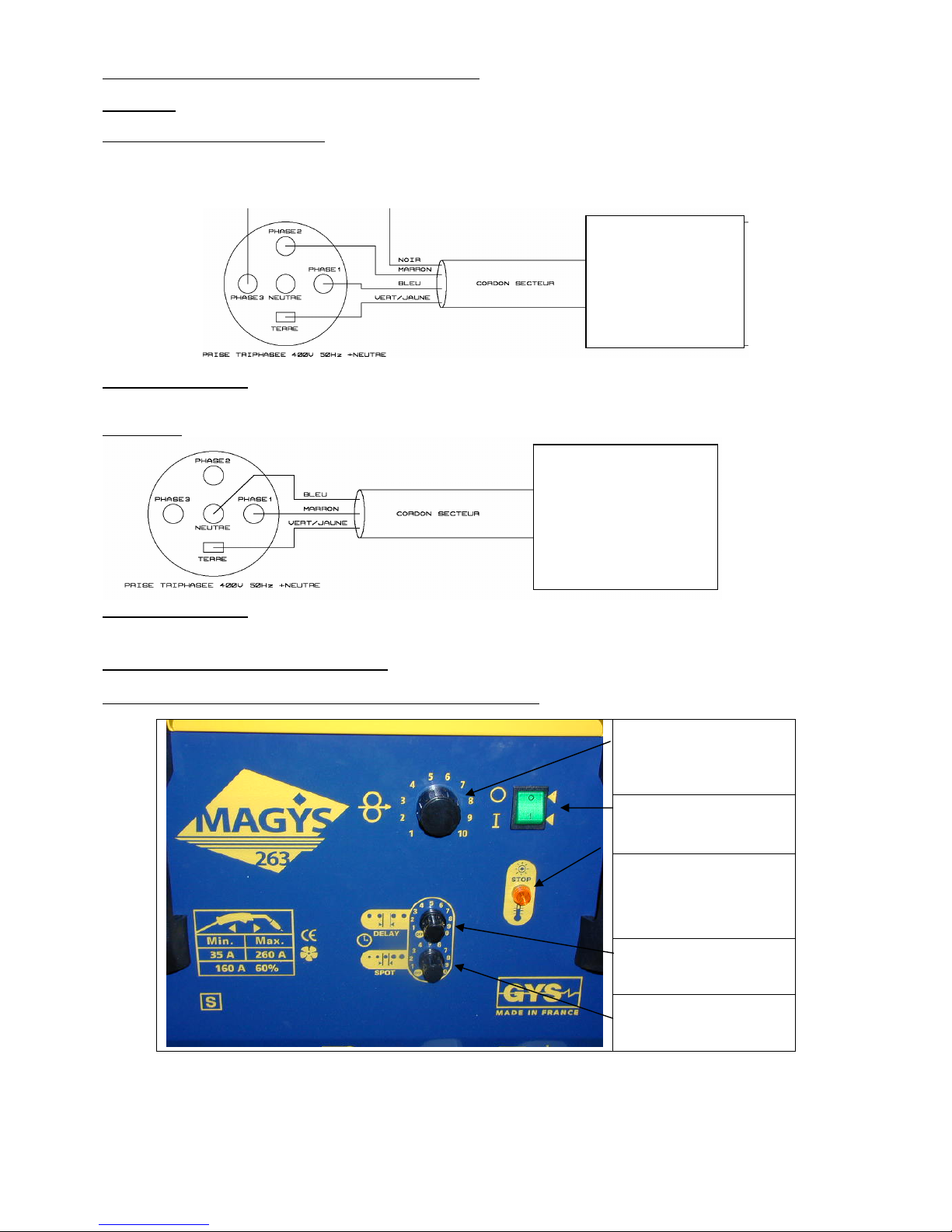
III / CONNECTIONS OF POWER SUPPLY CABLES
Electricity:
MAGYS 263 and GENEGYS 263 SF
Three phases 400V 50Hz. Use of the PHASE 1, PHASE 2, PHASE3 and EARTH CONNECTION on a three
phases plug (Don’t use NEUTRAL).
Protection of the line:
MAGYS 263 and GENEGYS 263 SF : Circuit breaker 16A curve D or fuse 16A type aM
MAGYS 261
Protection of the line:
MAGYS 261: Circuit breaker 40A curve D or fuse 40A type aM
IV/ DESCRIPTION OF THE MACHINE
MAGYS 261, MAGYS 263and GENEGYS 263 SF : Foreside (Higher part)
Potentiometer of
instructions wire speed
(except on GENEGYS
263 SF).
Commutator On / Off.
Thermal fault indicator: it
is switch on when the
machine is in fault.
Potentiometer of repose
time adjustment when you
use spot mode
Potentiometer of time
adjustment of welding
when you use spot mode.
Terminal
MAGYS 263 OR
GENEGYS 263 SF
Terminal
MAGYS 261
Page 4

4
MAGYS 263 et 261 : Foreside (Lower part)
Generator wire
feeder.
Commutator of the wire feeder.
Position I: generator wire feeder (origin).
Position II: separated wire feeder WF 212, 324 or 344 W (in option).
Gas connection: allow
to feed in gas either the
generator wire feeder or
a separated wire feeder
type WF. The
connection is situated
near the motor.
Commutator of
selection from the
output voltage.
Commutator 10
positions for
MAGYS 263 and
commutator 6
positions for
MAGYS 261.
Operating connector for
an application with a
separated wire feeder
type WF.
Positive terminal for an
application with a
separated wire feeder
type WF.
Negative terminal.
Allow to connect
either the main
clamp or the cable of
polarity choice of
the generator wire
feeder.
Cable for the polarity choice of the generator wire feeder. In application with gas, put the cable on the left terminal (+).
For an application without gas, put it on the negative.
The remaining terminal serve to connect the main clamp.
GENEGYS 263 SF: Foreside (Lower part)
Operating connector for
an application with
separated wire feeder
type WF.
Commutator of
selection from the
output voltage.
Negative Terminal
For an application
with gas, connect the
main clamp on the
terminal.
For an application
without gas, connect
the wire feeder bank
type WF on the
terminal.
Positive terminal
For an application with
gas, connect the wire
feeder bank type WF on
the terminal.
For an application
without gas, connect the
main clamp on the
terminal.
Gas connection of the
bank
VI / COMMISSIONING
5-2) Connection to gas bottle and gas choice
Screw down the regulator on gas bottle. This one is connected to MAGYS and GENEGYS by a pipe whose terminal end
is fixated on the electronic valve behind the machine. You must use clamps to avoid escape of gas.
Page 5

5
MAGYS 263 and MAGYS 261
Application with the wire feeder of the generator
Application with a separated wire feeder type WF
Screw down the gas connection from moto generator
wire feeder on the gas connection
Screw off the pipe of moto generator wire feeder and screw
down bank connection by integrating the pipe in the front
side hole.
For GENEGYS 263 SF machine, the gas connection of the bank is uniquely made on front side.
Gas choice:
STEEL MORE OR LESS ALLOYED
- Pure CO2 (not much used),
- Argon + CO2 (universal gas, often used),
- Argon + CO2 + O2 (not much used).
STAINLESS STEEL
- Argon + CO2 (often used),
- Argon + H + CO2 +N (not much used).
ALUMINIUM
- Pure argon (often used),
- Argon + Hé (not much used).
5-3) Connection to earth cable
For an application with a wire in normal polarity, you must connect the adapter earth clamp on the negative terminal and
take care to swivel from a ¼ the adapter.
For an application with a thread « without gas », you have to connect the main clamp to the positive terminal.
5-4) Connection of the torch
All torches are with a euro connection, which can be adapted on GYS machines.
5-5) Setting of rollers
Choose those in function of the wire diameter used and the type of wire (See following board). MAGYS 263 and 261
machines are delivered with rollers double groove 0,8 / 1 for steel.
Rollers double
groove
GYS Reference for MAGYS
263 and 261 and wire feeder
WF 324 and 344 W
0,6 / 0,8
041738
0,8 / 1
042094
0,8 / 1 ALU
042148
0,9 / 1,2 NO GAZ 042124
1 / 1,2
042117
1 / 1,2 ALU
042162
1,2 / 1,6
041752
1,2 / 1,6 ALU 041776
5-6) Setting of wire spool
Open the wire feeder compartment. Remove the swivel from the coil support. Take the coil and put it on the support
with taking care to block with base spin, then screw down again the swivel. For an application with a 5Kg coil (or
d=200), put the adapter between the support and the coil. For an application in steel wire place in position the capillary
tube
(for an application in aluminium see the paragraph VI).
Page 6

6
Slump the wire in the moto wire feeder entrance. Release the clamping at maximum. Close the plate of the moto wire feeder.
Press on the gate and tighten little by little the clamping handle until the motor start to drive the wire.
.
5-7) Brake adjustment from the coil support
You must block this one in function of the weight coil used.
Too blocked: the motor is in difficulty and the thread risk not to drive.
Release: the important coil inertia can drive the wire rolling after end welding.
VI / USING IN ALUMINIUM
The setting of the torch for Aluminium is fundamental.
The essential precautions are the following:
- Don’t use the brass capillary tube in the euro adapter, but use the
Teflon envelope, which must come until the moto-wire feeder
roller.
- In ALUMINIUM, use a contact tube of a diameter immediately
superior to the section of the wire used.
- Use ALU rollers identical with wire diameter.
VII / OPTION FOR MAGYS 263 et 261
MAGYS 263 and 261 machines are evolutives terminals. For origin machine, we can uniquely use this one with the
moto wire feeder. Then, we can advanced the product with separated wire feeder with equipping it with a WF wire
feeder and a contact batch from 5 or 10 meters.
When the machine is totally equipped, the choice of the moto wire feeder will be in function of the commutator position
in foreside.
1
4
3
2
Origin moto-wire feeder on
the generator
Option wire feeder WF
Page 7

7
Connection from a wire feeder WF to the generator
X / MAINTENANCE
You must clean out and replace regularly nozzle and contact batch of all projections. Use a spray of anti-pearl aerosol.
We advice you to clean the covering situated in the torch by blowing it with compressed air.
Gas pipe
Control cable
Power cable
To use a wire feeder WF,
tip the commutator on the
position II « wire feeder
WF
»
Don’t forget to transpose
the gas connection
situated behind the front
panel
 Loading...