


FR
02-31 / 92-100
ARCPULL 350
EN
DE
73502 V5 09/04/2024
32-61 / 92-100
62-91 / 92-100
Find user manuals in other languages
www.gys.fr

Manuel d’utilisation
Notice originale
Avertissements - Règles de sécurité ���������������������������������������������������������������������������������������������������������������������������3
1.
2. Description du matériel �����������������������������������������������������������������������������������������������������������������������������������������������������8
3. Alimentation et mise en marche���������������������������������������������������������������������������������������������������������������������������������10
3�1 Branchement sur groupe électrogène����������������������������������������������������������������������������������������������������������������������������������� 10
3�2 Utilisation de rallonge ��������������������������������������������������������������������������������������������������������������������������������������������������������� 10
3�3 Connexion du pistolet au générateur������������������������������������������������������������������������������������������������������������������������������������10
3�4 Mise à jour du produit �������������������������������������������������������������������������������������������������������������������������������������������������������� 11
4. Procédé de soudage de pièce rapportée par arc tiré ����������������������������������������������������������������������������������������11
5. Modèle de goujon et protection du bain de fusion ��������������������������������������������������������������������������������������������� 11
5�1 État de surface de la pièce support et décapage ������������������������������������������������������������������������������������������������������������������� 12
5�2 Épaisseur de la tôle support en fonction du diamètre du goujon �������������������������������������������������������������������������������������������� 12
5�3 Protection du bain de fusion ����������������������������������������������������������������������������������������������������������������������������������������������� 12
5�4 Choix de l’accessoire de soudure ���������������������������������������������������������������������������������������������������������������������������������������� 13
5�5 Polarité du pistolet ������������������������������������������������������������������������������������������������������������������������������������������������������������14
5�6 Cadence de soudage du poste ��������������������������������������������������������������������������������������������������������������������������������������������� 14
5�7 Positionnement des pinces de masse et souage d’arc �������������������������������������������������������������������������������������������������������� 14
6. Installation accessoires et réglage du pistolet ���������������������������������������������������������������������������������������������������15
6�1 Changement et ajustement longueur des tiges de prise de masse (réf� 059627) ���������������������������������������������������������������������15
6�2 Réglage d’un porte-goujon / porte-clou d’isolation ���������������������������������������������������������������������������������������������������������������� 16
6�2�1 Réglage porte goujon soudure sans férule en céramique ������������������������������������������������������������������������������������������������ 17
6�2�2 Réglage porte goujon soudure avec férule en céramique ������������������������������������������������������������������������������������������������ 17
6�3 Utilisation de l’accessoire pour pose d’anneaux de tirage (réf� 059610) ����������������������������������������������������������������������������������� 17
6�4 Utilisation du coret ArcPull Rivet Box1 350 – 24kN (réf. 064584) ������������������������������������������������������������������������������������������ 18
6�5 Utilisation du coret ArcPull Rivet Box2 350 – 50kN (réf. 073388) ������������������������������������������������������������������������������������������ 18
6�6 Utilisation du coret Stud Hold Box 350 (réf. 068339) ����������������������������������������������������������������������������������������������������������� 19
6�7 Utilisation de l’adaptateur pour férule en céramique (réf� 075979)������������������������������������������������������������������������������������������20
6�7�1 Choix du support férule céramique �������������������������������������������������������������������������������������������������������������������������������20
6�7�2 Procédure de changement d’adaptateur de céramique ���������������������������������������������������������������������������������������������������21
6�7�3 Mise en place de l’accessoire sur le pistolet ������������������������������������������������������������������������������������������������������������������� 21
6.8 Utilisation des corets ArcPull 350 Dicult Access (réf. 070813) ��������������������������������������������������������������������������������������������22
7. Manipulation du pistolet �����������������������������������������������������������������������������������������������������������������������������������������������22
7�1 Soudure des anneaux de tirage ������������������������������������������������������������������������������������������������������������������������������������������� 22
7�2 Soudure de pièces rapportées hors anneaux de tirage ����������������������������������������������������������������������������������������������������������23
8. Mode de fonctionnement du produit �����������������������������������������������������������������������������������������������������������������������23
8.1 Soudage en Mode Synergique ��������������������������������������������������������������������������������������������������������������������������������������������� 24
8.1.1 Type de pièces à souder ����������������������������������������������������������������������������������������������������������������������������������������������25
8.1.2 Épaisseur de la tôle support ����������������������������������������������������������������������������������������������������������������������������������������� 25
8.2 Soudage en Mode Manuel �������������������������������������������������������������������������������������������������������������������������������������������������� 25
8.3 Liste des messages achés en bas de l’écran de soudage ���������������������������������������������������������������������������������������������������� 26
8.4 Menu principal ������������������������������������������������������������������������������������������������������������������������������������������������������������������� 27
8.4.1 Menu Réglage en mode synergique ������������������������������������������������������������������������������������������������������������������������������27
8.4.2 Menu Réglage en mode manuel �����������������������������������������������������������������������������������������������������������������������������������28
8.4.3 Menu Programmes ������������������������������������������������������������������������������������������������������������������������������������������������������29
8.4.4 Menu Conguration �����������������������������������������������������������������������������������������������������������������������������������������������������29
9. Message d’erreur, anomalies, causes, remèdes ��������������������������������������������������������������������������������������������������31
Schéma électrique et pièces de rechange �������������������������������������������������������������������������������������������������������������92
10.
10�1 Générateur ������������������������������������������������������������������������������������������������������������������������������������������������������������������������92
10�2 Pistolet ����������������������������������������������������������������������������������������������������������������������������������������������������������������������������� 95
Caractéristiques techniques ����������������������������������������������������������������������������������������������������������������������������������������97
11.
ARCPULL 350
2

Manuel d’utilisation
Notice originale
1. AVERTISSEMENTS - RÈGLES DE SÉCURITÉ
ARCPULL 350
CONSIGNE GÉNÉRALE
Ces instructions doivent être lues et bien comprises avant toute opération.
Toute modication ou maintenance non indiquée dans le manuel ne doit pas être entreprise.
Tout dommage corporel ou matériel dû à une utilisation non conforme aux instructions de ce manuel ne pourra être retenu à la charge du fabricant.
En cas de problème ou d’incertitude, veuillez consulter une personne qualiée pour manier correctement l’installation.
ENVIRONNEMENT
Ce matériel doit être utilisé uniquement pour faire des opérations de soudage dans les limites indiquées par la plaque signalétique et/ou le manuel.
Il faut respecter les directives relatives à la sécurité. En cas d’utilisation inadéquate ou dangereuse, le fabricant ne pourra être tenu responsable.
L’installation doit être utilisée dans un local sans poussière, ni acide, ni gaz inammable ou autres substances corrosives. Il en est de même pour son
stockage. S’assurer d’une circulation de l’air lors de l’utilisation.
Plage de température :
Utilisation entre -10 et +40°C (+14 et +104°F).
Stockage entre -20 et +55°C (-4 et 131°F).
Humidité de l’air :
Inférieur ou égal à 50% à 40°C (104°F).
Inférieur ou égal à 90% à 20°C (68°F).
Altitude :
Jusqu’à 1000m au-dessus du niveau de la mer (3280 pieds)
PROTECTION INDIVIDUELLE ET DES AUTRES
Le soudage à l’arc peut être dangereux et causer des blessures graves voire mortelles.
Le soudage expose les individus à une source dangereuse de chaleur, de rayonnement lumineux de l’arc, de champs électromagnétiques (attention
au porteur de pacemaker), de risque d’électrocution, de bruit et d’émanations gazeuses.
Pour bien se protéger et protéger les autres, respecter les instructions de sécurité suivantes :
FR
An de se protéger de brûlures et rayonnements, porter des vêtements sans revers, isolants, secs, ignifugés et en bon état, qui
couvrent l’ensemble du corps.
Utiliser des gants qui garantissent l’isolation électrique et thermique.
Utiliser un masque ou des lunettes de protection ayant une teinte entre 5 et 9. Protéger les yeux lors des opérations de nettoyage.
Les lentilles de contact sont particulièrement proscrites.
Il est parfois nécessaire de délimiter les zones par des rideaux ignifugés pour protéger la zone de soudage des rayons de l’arc, des
projections et des déchets incandescents.
Informer les personnes dans la zone de soudage de ne pas xer les rayons de l’arc ni les pièces en fusion et de porter les vêtements
adéquats pour se protéger.
Utiliser un casque contre le bruit si le procédé de soudage atteint un niveau de bruit supérieur à la limite autorisée (de même pour
toute personne étant dans la zone de soudage).
Tenir à distance des parties mobiles (ventilateur) les mains, cheveux, vêtements.
Les pièces qui viennent d’être soudées sont chaudes et peuvent provoquer des brûlures lors de leur manipulation. Lors d’intervention
d’entretien sur le pistolet, il faut s’assurer qu’il soit susamment froid en attendant au moins 10 minutes avant toute intervention. Il
est important de sécuriser la zone de travail avant de la quitter an de protéger les personnes et les biens.
FUMÉES DE SOUDAGE ET GAZ
Les fumées, gaz et poussières émis par le soudage sont dangereux pour la santé. Il faut prévoir une ventilation susante, un
apport d’air est parfois nécessaire. Un masque à air frais peut être une solution en cas d’aération insusante.
Vérier que l’aspiration est ecace en la contrôlant par rapport aux normes de sécurité.
Attention le soudage dans des milieux de petites dimensions nécessite une surveillance à distance de sécurité. Par ailleurs le soudage de certains
matériaux contenant du plomb, cadmium, zinc ou mercure voire du béryllium peuvent être particulièrement nocifs, dégraisser également les pièces
avant de les souder.
3

Manuel d’utilisation
Notice originale
Les bouteilles doivent être entreposées dans des locaux ouverts ou bien aérés. Elles doivent être en position verticale et maintenue à un support ou
sur un chariot.
Le soudage doit être proscrit à proximité de graisse ou de peinture.
RISQUE DE FEU ET D’EXPLOSION
Protéger entièrement la zone de soudage, les matières inammables doivent être éloignées d’au moins 11 mètres.
Un équipement anti-feu doit être présent à proximité des opérations de soudage.
Attention aux projections de matières chaudes ou d’étincelles et même à travers des ssures, elles peuvent être source d’incendie ou d’explosion.
Éloigner les personnes, les objets inammables et les containers sous pressions à une distance de sécurité susante.
Le soudage dans des containers ou des tubes fermés est à proscrire et dans le cas où ils sont ouverts il faut les vider de toute matière inammable
ou explosive (huile, carburant, résidus de gaz …).
Les opérations de meulage ne doivent pas être dirigées vers la source de courant de soudage ou vers des matières inammables.
BOUTEILLES DE GAZ
Le gaz sortant des bouteilles peut être source de suocation en cas de concentration dans l’espace de soudage (bien ventiler).
Le transport doit être fait en toute sécurité : bouteilles fermées et la source de courant de soudage éteinte. Elles doivent être
entreposées verticalement et maintenues par un support pour limiter le risque de chute.
ARCPULL 350
Fermer la bouteille entre deux utilisations. Attention aux variations de température et aux expositions au soleil.
La bouteille ne doit pas être en contact avec une amme, un arc électrique, une torche, une pince de masse ou toutes autres sources de chaleur ou
d’incandescence.
Veiller à la tenir éloignée des circuits électriques et de soudage et donc ne jamais souder une bouteille sous pression.
Attention lors de l’ouverture du robinet de la bouteille, il faut éloigner la tête la robinetterie et s’assurer que le gaz utilisé est approprié au procédé de
soudage.
SÉCURITÉ ÉLECTRIQUE
Le réseau électrique utilisé doit impérativement avoir une mise à la terre. Utiliser la taille de fusible recommandée sur le tableau
signalétique.
Une décharge électrique peut être une source d’accident grave direct ou indirect, voire mortel.
Ne jamais toucher les parties sous tension à l’intérieur comme à l’extérieur de la source de courant sous-tension (Torches, pinces, câbles, électrodes)
car celles-ci sont branchées au circuit de soudage.
Avant d’ouvrir la source de courant de soudage, il faut la déconnecter du réseau et attendre 2 minutes an que l’ensemble des condensateurs soit
déchargé.
Ne pas toucher en même temps le porte-électrode et les tiges de retour de masse.
Veiller à changer les câbles et torches, par des personnes qualiées et habilitées, si ceux-ci sont endommagés. Dimensionner la section des câbles
en fonction de l’application. Toujours utiliser des vêtements secs et en bon état pour s’isoler du circuit de soudage. Porter des chaussures isolantes,
quel que soit le milieu de travail.
CLASSIFICATION CEM DU MATÉRIEL
Ce matériel de Classe A n’est pas prévu pour être utilisé dans un site résidentiel où le courant électrique est fourni par le réseau
public d’alimentation basse tension. Il peut y avoir des dicultés potentielles pour assurer la compatibilité électromagnétique
dans ces sites, à cause des perturbations conduites, aussi bien que rayonnées à fréquence radioélectrique.
CEI 61000-3-12
4
Sous réserve que l’impédance de réseau public d’alimentation basse tension au point de couplage commun soit inférieure à
Zmax = 0.20 Ohms, ce matériel est conforme à la CEI 61000-3-11 et peut être connecté aux réseaux publics d’alimentation
basse tension. Il est de la responsabilité de l’installateur ou de l’utilisateur du matériel de s’assurer, en consultant l’opérateur
du réseau de distribution si nécessaire, que l’impédance de réseau est conforme aux restrictions d’impédance.
Ce matériel est conforme à la CEI 61000-3-12.

Manuel d’utilisation
Notice originale
ÉMISSIONS ELECTRO-MAGNETIQUES
ARCPULL 350
Le courant électrique passant à travers n’importe quel conducteur produit des champs électriques et magnétiques (EMF) localisés.
Le courant de soudage produit un champ électromagnétique autour du circuit de soudage et du matériel de soudage.
Les champs électromagnétiques EMF peuvent perturber certains implants médicaux, par exemple les stimulateurs cardiaques. Des mesures
de protection doivent être prises pour les personnes portant des implants médicaux. Par exemple, restrictions d’accès pour les passants ou une
évaluation de risque individuelle pour les soudeurs.
Tous les soudeurs devraient utiliser les procédures suivantes an de minimiser l’exposition aux champs électromagnétiques provenant du circuit de
soudage:
• positionner les câbles de soudage ensemble – les xer les avec une attache, si possible;
• se positionner (torse et tête) aussi loin que possible du circuit de soudage;
• ne jamais enrouler les câbles de soudage autour du corps;
• ne pas positionner le corps entre les câbles de soudage. Tenir les deux câbles de soudage sur le même côté du corps;
• raccorder le câble de retour à la pièce mise en œuvre aussi proche que possible à la zone à souder;
• ne pas travailler à côté de la source de courant de soudage, ne pas s’assoir dessus ou ne pas s’y adosser ;
• ne pas souder lors du transport de la source de courant de soudage ou le dévidoir.
Les porteurs de stimulateurs cardiaques doivent consulter un médecin avant d’utiliser ce matériel.
L’exposition aux champs électromagnétiques lors du soudage peut avoir d’autres eets sur la santé que l’on ne connaît pas
encore.
RECOMMANDATIONS POUR ÉVALUER LA ZONE ET L’INSTALLATION DE SOUDAGE
Généralités
L’utilisateur est responsable de l’installation et de l’utilisation du matériel de soudage à l’arc suivant les instructions du fabricant. Si des perturbations
électromagnétiques sont détectées, il doit être de la responsabilité de l’utilisateur du matériel de soudage à l’arc de résoudre la situation avec
l’assistance technique du fabricant. Dans certains cas, cette action corrective peut être aussi simple qu’une mise à la terre du circuit de soudage. Dans
d’autres cas, il peut être nécessaire de construire un écran électromagnétique autour de la source de courant de soudage et de la pièce entière avec
montage de ltres d’entrée. Dans tous les cas, les perturbations électromagnétiques doivent être réduites jusqu’à ce qu’elles ne soient plus gênantes.
FR
Évaluation de la zone de soudage
Avant d’installer un matériel de soudage à l’arc, l’utilisateur doit évaluer les problèmes électromagnétiques potentiels dans la zone environnante. Ce
qui suit doit être pris en compte:
a) la présence au-dessus, au-dessous et à côté du matériel de soudage à l’arc d’autres câbles d’alimentation, de commande, de signalisation et de
téléphone;
b) des récepteurs et transmetteurs de radio et télévision;
c) des ordinateurs et autres matériels de commande;
d) du matériel critique de sécurité, par exemple, protection de matériel industriel;
e) la santé des personnes voisines, par exemple, emploi de stimulateurs cardiaques ou d’appareils contre la surdité;
f) du matériel utilisé pour l’étalonnage ou la mesure;
g) l’immunité des autres matériels présents dans l’environnement.
L’utilisateur doit s’assurer que les autres matériels utilisés dans l’environnement sont compatibles. Cela peut exiger des mesures de protection
supplémentaires;
h) l’heure du jour où le soudage ou d’autres activités sont à exécuter.
La dimension de la zone environnante à prendre en compte dépend de la structure du bâtiment et des autres activités qui s’y déroulent. La zone
environnante peut s’étendre au-delà des limites des installations.
Évaluation de l’installation de soudage
Outre l’évaluation de la zone, l’évaluation des installations de soudage à l’arc peut servir à déterminer et résoudre les cas de perturbations. Il convient
que l’évaluation des émissions comprenne des mesures in situ comme cela est spécié à l’Article 10 de la CISPR 11. Les mesures in situ peuvent
également permettre de conrmer l’ecacité des mesures d’atténuation.
RECOMMANDATIONS SUR LES MÉTHODES DE RÉDUCTION DES ÉMISSIONS ÉLECTROMAGNETIQUES
a. Réseau public d’alimentation: Il convient de raccorder le matériel de soudage à l’arc au réseau public d’alimentation selon les recommandations
du fabricant. Si des interférences se produisent, il peut être nécessaire de prendre des mesures de prévention supplémentaires telles que le ltrage
du réseau public d’alimentation. Il convient d’envisager de blinder le câble d’alimentation dans un conduit métallique ou équivalent d’un matériel de
soudage à l’arc installé à demeure. Il convient d’assurer la continuité électrique du blindage sur toute sa longueur. Il convient de raccorder le blindage
à la source de courant de soudage pour assurer un bon contact électrique entre le conduit et l’enveloppe de la source de courant de soudage.
b. Maintenance du matériel de soudage à l’arc : Il convient que le matériel de soudage à l’arc soit soumis à l’entretien de routine suivant les
recommandations du fabricant. Il convient que tous les accès, portes de service et capots soient fermés et correctement verrouillés lorsque le matériel
de soudage à l’arc est en service. Il convient que le matériel de soudage à l’arc ne soit modié en aucune façon, hormis les modications et réglages
mentionnés dans les instructions du fabricant. Il convient, en particulier, que l’éclateur d’arc des dispositifs d’amorçage et de stabilisation d’arc soit
réglé et entretenu suivant les recommandations du fabricant.
c. Câbles de soudage : Il convient que les câbles soient aussi courts que possible, placés l’un près de l’autre à proximité du sol ou sur le sol.
d. Liaison équipotentielle : Il convient d’envisager la liaison de tous les objets métalliques de la zone environnante. Toutefois, des objets métalliques
reliés à la pièce à souder accroissent le risque pour l’opérateur de chocs électriques s’il touche à la fois ces éléments métalliques et l’électrode. Il
convient d’isoler l’opérateur de tels objets métalliques.
5

Manuel d’utilisation
Notice originale
e. Mise à la terre de la pièce à souder : Lorsque la pièce à souder n’est pas reliée à la terre pour la sécurité électrique ou en raison de ses
dimensions et de son emplacement, ce qui est le cas, par exemple, des coques de navire ou des charpentes métalliques de bâtiments, une connexion
raccordant la pièce à la terre peut, dans certains cas et non systématiquement, réduire les émissions. Il convient de veiller à éviter la mise à la terre
des pièces qui pourrait accroître les risques de blessure pour les utilisateurs ou endommager d’autres matériels électriques. Si nécessaire, il convient
que le raccordement de la pièce à souder à la terre soit fait directement, mais dans certains pays n’autorisant pas cette connexion directe, il convient
que la connexion soit faite avec un condensateur approprié choisi en fonction des réglementations nationales.
f. Protection et blindage : La protection et le blindage sélectifs d’autres câbles et matériels dans la zone environnante peuvent limiter les problèmes
de perturbation. La protection de toute la zone de soudage peut être envisagée pour des applications spéciales.
TRANSPORT ET TRANSIT DE LA SOURCE DE COURANT DE SOUDAGE
La source de courant de soudage est équipée d’une poignée supérieure permettant le portage à la main. Attention à ne pas sous-
évaluer son poids. La poignée n’est pas considérée comme un moyen d’élingage.
Ne pas utiliser les câbles ou pistolet pour déplacer la source de courant de soudage. Elle doit être déplacée en position verticale.
Ne pas faire transiter la source de courant au-dessus de personnes ou d’objets.
Ne jamais soulever une bouteille de gaz et la source de courant en même temps. Leurs normes de transport sont distinctes.
INSTALLATION DU MATÉRIEL
• Mettre la source de courant de soudage sur un sol dont l’inclinaison maximum est de 10°.
• La source de courant de soudage doit être à l’abri de la pluie battante et ne pas être exposée aux rayons du soleil.
• Le matériel est de degré de protection IP33, signiant :
- une protection contre l’accès aux parties dangereuses des corps solides de diam >2.5 mm et,
- une protection contre la pluie dirigée à 60° par rapport à la verticale.
Ce matériel peut donc être utilisé à l’extérieur en accord avec l’indice de protection IP33.
ARCPULL 350
Les courants de soudage vagabonds peuvent détruire les conducteurs de terre, endommager l’équipement et les dispositifs
électriques et causer des échauements de composants pouvant entrainer un incendie.
- Toutes les connexions de soudages doivent être connectées fermement, les vérier régulièrement !
- S’assurer que la xation de la pièce est solide et sans problèmes électriques !
- Attacher ou suspendre tous les éléments conducteurs d’électricité de la source de soudage comme le châssis, le chariot et les systèmes de levage
pour qu’ils soient isolés !
- Ne pas déposer d’autres équipements comme des perceuses, dispositifs d’autage, etc. sur la source de soudage, le chariot, ou les systèmes de
levage sans qu’ils soient isolés !
- Toujours déposer les torches de soudage ou porte-électrodes sur une surface isolée quand ils ne sont pas utilisés !
Les câbles d’alimentation, de rallonge et de soudage doivent être totalement déroulés an d’éviter toute surchaue.
Le fabricant n’assume aucune responsabilité concernant les dommages provoqués à des personnes et objets dus à une utilisation
incorrecte et dangereuse de ce matériel.
ENTRETIEN / CONSEILS
• L’entretien ne doit être eectué que par une personne qualiée. Un entretien annuel est conseillé.
• Couper l’alimentation en débranchant la prise, et attendre deux minutes avant de travailler sur le matériel. À l’intérieur, les
tensions et intensités sont élevées et dangereuses.
• Contrôler régulièrement l’état du cordon d’alimentation. Si le câble d’alimentation est endommagé, il doit être remplacé par le fabricant, son
service après-vente ou une personne de qualication similaire, an d’éviter tout danger.
• Ne pas utiliser cette source de courant de soudage pour dégeler des canalisations, recharger des batteries/accumulateurs ou démarrer des
moteurs.
6

Manuel d’utilisation
Notice originale
2. DESCRIPTION DU MATÉRIEL
.
ARCPULL 350 est un poste à souder par arc-tiré inverter monophasé qui permet de souder pièces rapportées (goujons, goujons à letage interne, clous d’isolation, anneaux de tirage, tiges d’extraction de rivets, etc.) sur des matériaux à base aluminium ou acier. Il dispose d’un mode de fonctionnement Synergique, d’un mode de fonctionnement
Manuel. Le menu Programmes permet de stocker et rappeler des congurations de soudure.
Fig 1 : Vue extérieure du générateur
1
8
ARCPULL 350
FR
5
2
6
4
3
1 Clavier
2 Commutateur M/A
3 Texas positive pour faisceau pistolet
4 Texas négative pour faisceau pistolet
5 Embase pour connecteur de contrôle faisceau pistolet
6 Sortie gaz pour faisceau pistolet
7 Entrée gaz connectée à la bouteille
8 Capuchon de protection port USB de mise à jour
7
7

Manuel d’utilisation
PROTOTYPE
Notice originale
Fig 2 : Vue extérieure du pistolet et son IHM (sans fourche de soudure ni accessoire)
3
ARCPULL 350
2
1
1 Gâchette
2 Écrou moleté du porte-électrode
3 Molette de verrouillage des tiges
4 Tiges de prise de masse
5 Connecteur contrôle faisceau pistolet
6 Texas positive
7 Texas négative
8 Raccord gaz
9 LED ready (vert)
10 LED contact (bleu)
11 LED défaut (rouge)
4
6
7
5
8
9
11
10
ArcPull Rivet box1
350 – 24kN
ArcPull Rivet box2
350 – 50kN
064584 073388 064591 (068339) 075979 060777 059610
Chariot Weld 810 Câble de masse
double pince 350A
037489 070714 070813 079922 059627
8
Coret porte goujon
M4 à M8
Coret porte goujon
M4 à M8 - Dicult
Access
Adaptateur
céramique Ø6 et Ø8
Thermomètre
infrarouge
Pistolet à air chaud
(livré sans cartouche)
Tige de reprise
Porte anneau de
tirage

Manuel d’utilisation
Notice originale
3. ALIMENTATION ET MISE EN MARCHE
ARCPULL 350
• Ce produit est livré avec une prise 16 A de type CEE7/7 et doit être branché à une installation électrique monophasée avec neutre relié terre, comprise entre 208 VAC et 240 VAC (50 - 60 Hz). Le courant eectif absorbé (I1e) est
indiqué sur l’appareil pour les conditions d’utilisation maximales.
Vérier que l’installation électrique et ses protections (fusible et/ou disjoncteur) sont compatibles avec le courant
nécessaire en utilisation. Ce matériel est conçu pour pouvoir fonctionner sur une installation électrique équipée d’un
disjoncteur 16A courbe C, D ou K.
Dans certains pays, il peut être nécessaire de changer la prise pour permettre une utilisation aux conditions maxi-
males. L’utilisateur doit s’assurer de l’accessibilité de la prise.
• La mise en marche s’eectue en positionnant le commutateur M/A sur « | »
• L’appareil se met en protection si la tension d’alimentation est supérieure à 265 Vac (le mes-
sage DEFAUT SECTEUR est aché à l’écran). Le fonctionnement normal reprend dès que la
tension d’alimentation revient dans sa plage nominale.
3.1. BRANCHEMENT SUR GROUPE ÉLECTROGÈNE
Ce matériel peut fonctionner avec des groupes électrogènes monophasés à condition qu’ils répondent aux exigences
suivantes :
- La tension doit être alternative, réglée comme spéciée (208-240 Vac) et de tension crête inférieure à 400 V,
- La fréquence doit être comprise entre 50 et 60 Hz.
- La puissance doit être de 15 kVA au moins.
Il est impératif de vérier ces conditions, car de nombreux groupes électrogènes produisent des pics de haute tension
pouvant endommager le matériel.
FR
3.2. UTILISATION DE RALLONGE
Ce matériel peut être raccordé à l’installation électrique au moyen d’une rallonge à condition qu’elle réponde aux exigences suivantes :
- Rallonge monophasée avec conducteur de terre
- La longueur ne doit pas dépasser 10 m
- La section des conducteurs ne doit pas être inférieure à 2.5 mm²
3.3. CONNEXION DU PISTOLET AU GÉNÉRATEUR
La connexion et déconnexion du connecteur de contrôle du pistolet à l’embase du générateur doit impérativement se faire avec
un générateur éteint.
La bague du connecteur de contrôle du pistolet doit toujours être
vissée correctement à l’embase du générateur avant la mise en
marche du produit.
Il est possible de connecter un pistolet d’ArcPull 700 sur ce générateur. Dans ce cas, utiliser des adaptateurs texas
25mm² -> 50mm² ( 2 x 038127) pour la connexion des texas du pistolet aux embases du générateur.
9

Manuel d’utilisation
Notice originale
3.4. MISE À JOUR DU PRODUIT
Le produit possède une connectique USB en face avant protégée par un capuchon, pour mettre à jour son logiciel (ajout de synergies, de fonctionnalités).
Contacter votre revendeur, pour plus de détails.
4. PROCÉDÉ DE SOUDAGE DE PIÈCE RAPPORTÉE PAR ARC TIRÉ
L’arc tiré permet de souder des pièces rapportées (anneau de tirage, goujons, clous, etc.) sur une pièce support en
amenant les deux pièces en fusion au moyen d’un arc électrique et en les mettant toutes les deux en contact.
Rappel du principe de soudure par arc tiré (pour plus de détail, se référer à la norme ISO 14555) :
On distingue 4 grandes étapes : l’amorçage, le décapage, l’arc et l’accroche
Phase Amorçage Décapage Arc Accroche
T (ms) 0 à 200 ms 10 à 800 ms 0 à 50 ms
I (A) ≈80-150 A 50 à 60 A 50 à 350 A ≈80-150 A
ARCPULL 350
L’amorçage : la pièce rapportée (anneau de tirage, goujons, etc.) est mise en contact avec la tôle support. Un appui
sur la gâchette démarre le processus de soudage : le générateur envoie du courant dans le goujon, l’axe du pistolet
se lève légèrement, un arc électrique de faible intensité est alors créé.
Le décapage : cette phase pourrait également être appelée préchauage. Le générateur régule un courant pour
assurer un arc électrique de faible intensité, la chaleur générée par cet arc permet :
- de brûler les impuretés de la tôle support (graisses, huiles, zingage électrolytique).
- de préchauer les deux pièces, et donc de limiter le choc thermique de l’arc de soudure, an d’améliorer la qualité
de la soudure.
Lors de cette phase ni la pièce rapportée, ni la tôle support, ne rentre en fusion. De même, cette phase ne permet pas
de dégager la couche de zinc de tôle galvanisée.
L’arc : le générateur augmente signicativement le courant pour créer un arc très énergétique créant un bain de fusion sur la tôle support et entrainant la fusion de l’extrémité de la pièce rapportée.
L’accroche : Le pistolet plonge la pièce rapportée dans le bain en fusion.
5. MODÈLE DE GOUJON ET PROTECTION DU BAIN DE FUSION
Les types de pièces rapportées (forme, dimensions, matériau) dédiés à l’arc tiré sont listés dans la norme ISO 13918.
En plus des pièces rapportées en acier bas carbone, en acier inoxydable et acier cuivré, le produit peut également
souder certaines pièces rapportées en aluminium.
10
Manuel d’utilisation
Notice originale
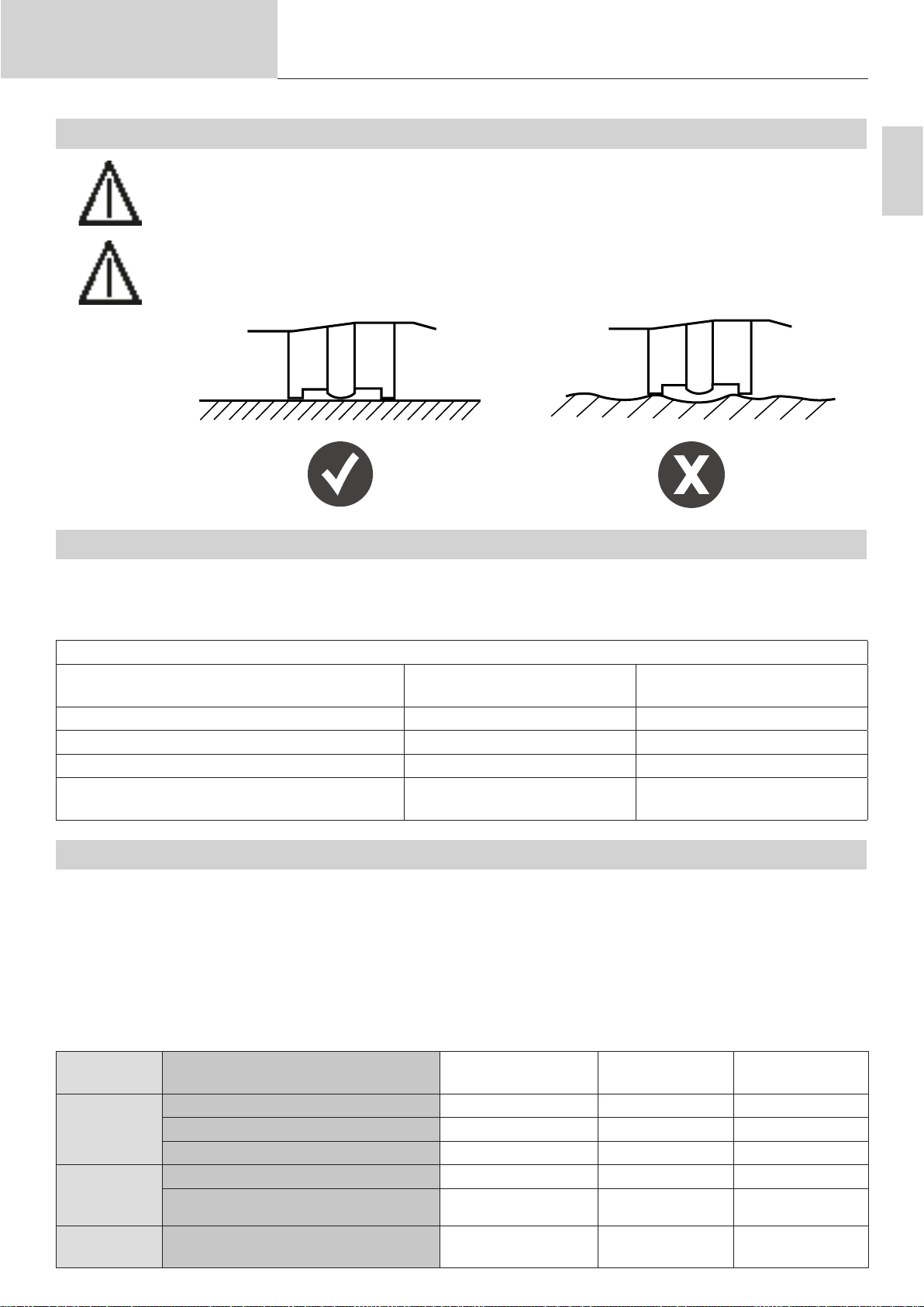
5.1. ÉTAT DE SURFACE DE LA PIÈCE SUPPORT ET DÉCAPAGE
ARCPULL 350
La soudure de pièce rapportée doit être eectuée sur une pièce support exempte de graisse. Il est
également nécessaire de décaper cette pièce support si celle-ci à un traitement chimique (couche
de zinc pour l’acier galvanisé, anticorrosif pour les aciers ayant subi un traitement thermique, alu-
mine pour les aluminiums).
La soudure de pièce rapportée, et particulièrement les pièces en aluminium, doit être eectuée sur
une pièce support plane.
5.2. ÉPAISSEUR DE LA TÔLE SUPPORT EN FONCTION DU DIAMÈTRE DU GOUJON
À l’exception des applications spéciques liées à la carrosserie automobile (pose d’anneau de tirage, l’épaisseur de
la tôle support ne doit pas être inférieure à ¼ du diamètre de la base de la pièce rapportée dans le cas de l’acier, et ½
du diamètre dans le cas de l’aluminium.
FR
Exemples (liste non exhaustive)
Pièces à souder
(selon l’ISO 13918)
Goujon acier type DD M8 8 mm 2 mm
Goujon acier type PD M6 5.35 mm 1.3 mm
Goujon AlMg temps court type PS M8 9 mm 2 mm
Goujon AlMg temps court type IS (letage in-
terne) M5
5.3. PROTECTION DU BAIN DE FUSION
En fonction du matériau à souder, une protection du bain de fusion par férule en céramique ou par protection gazeuse
peut-être nécessaire.
Le tableau ci-dessous liste le gaz qu’il est recommandé d’utiliser en fonction de la pièce à souder et de son matériau.
Ces gaz maximisent la tenue de la soudure et correspondent au gaz à utiliser lorsque le poste fonctionne en Mode
Synergique (voir §8.1).
Ce tableau est donné à titre indicatif, des essais de soudure préalables sont conseillés.
Matière Pièce rapportée à souder Férule en
Aluminium
(Al, AlMg,
AlMgSi)
Acier bas
carbone
(Fe)
Acier cuivré
(FeCu)
Anneau de tirage aluminium Impossible Argon Non recommandé
Goujon, goujon à letage interne Impossible ArHe 30% Impossible
Goujon à letage grossier Impossible ArHe 30% Impossible
Anneau de tirage acier Impossible ArCO² 8% Possible
Goujon, goujon à letage interne OK ArCO² 8% Non recommandé
Goujon, goujon à letage interne clou
d’isolation, goujon à letage grossier
Diamètre base Épaisseur de tôle minimum
9 mm 2 mm
Gaz Sans gaz
céramique
Impossible ArCO² 8% Non recommandé
11

Manuel d’utilisation
Notice originale
ARCPULL 350
Inox
Goujon, goujon à letage interne Non recommandé ArCO² 2% Non recommandé
Tiges extracteur de rivet en inox Non recommandé ArCO² 8% Non recommandé
Accessoire à utiliser
Coret porte-goujon
(
064591
) équipé de
l’adaptateur support
férule céramique
standard (
075979
)
Coret porte goujon (
Coret porte goujon dicult access
(
070813
)
ArcPull Rivet box 1 350 24 kN
(
064584
)
ArcPull Rivet box 2 350 50kN
(
073388
)
064591
)
En cas d’utilisation de protection gazeuse, le débit de gaz doit être réglé entre 12 l et 15 l/min.
Note : Dans le cas de soudure aluminium, il est possible d’utiliser de l’argon pur (Ar) en remplacement du mélange
argon-hélium à 30% (ArHe30%).
Ne pas dépasser 5 N.m pour le serrage d’un raccord à l’entrée de gaz du matériel.
5.4. CHOIX DE L’ACCESSOIRE DE SOUDURE
Le choix de l’accessoire de soudage à utiliser est déterminé en fonction du type de pièce rapportée à souder (type,
dimensions, matériau), de la position de soudage, et de la protection adéquate (gaz, sans gaz et férule en céramique). Le tableau ci-dessous donne une aide sur le choix de cet accessoire.
Accessoire Adaptateur sup-
port férule céramique standard
(075979)
Pièces à souder
(selon l’ISO 13918)
Longueur de la
pièce à souder
Diamètre max de la
base de la pièce à
souder
Goujon PD, RD, DD
Pion UD
De 25 mm à
65 mm
À plat (PA) si > 6 mm
Sans restriction si ≤ 6 mm
Coret porte-goujon (064591)
Goujon PD, RD, DD
et temps court PS
Goujon letage
interne temps court
PS
Pion UD et temps
court US
Clou d’isolation
De 25 mm à
30 mm
(100 mm pour les
clous d’isolation)
Position de soudage (selon l’ISO 6947)
Coret porte
goujon Dicult
Access (070813)
Goujon PD, RD, DD
et temps court PS
Goujon letage
interne temps court
PS
Pion UD et temps
court US
Clou d’isolation
De 25 mm à
70 mm
(100 mm pour les
clous d’isolation)
ArcPull Rivet
box1 350 – 24kN
(064584)
ArcPull Rivet box2
350 – 50kN (Réf
073388)
Tige d’extraction de
rivet
Sans restriction
Porte anneau
(059610)
Anneau de tirage
12

Manuel d’utilisation
5.5. POLARITÉ DU PISTOLET
Notice originale
ARCPULL 350
La polarité du pistolet a un impact sur la qualité de la soudure.
Dépendant du type de pièce à souder, et de sa matière, il est préférable de connecter la texas positive du pistolet à la
borne + ou – du générateur. Ci-dessous le tableau du choix de polarité retenu par GYS.
Pièce rapportée à souder Raccordement de la
texas positive du pistolet
(repère rouge)
Anneau de tirage aluminium Texas négative du
générateur (-)
Anneau de tirage acier Texas positive du
générateur (+)
Tige d’extraction de rivets Texas négative du
générateur (-)
Goujon, goujon à letage interne,
clou d’isolation en acier cuivré
5.6. CADENCE DE SOUDAGE DU POSTE
La cadence de soudage du poste est calculée dynamiquement pour ne pas dépasser un courant eectif prélevé sur le
réseau de 16A. Dépendant du type de pièce rapportée à souder, et donc du courant et du temps de soudure, le poste
aura un temps de repos entre deux soudures plus ou moins long.
Pièce à souder Cadence
Anneau de tirage AlMg de 1.5 mm sur épaisseur de
1 mm
Tige d’extraction de rivet Ø5 17/min
Goujon acier cuivré M6 sur épaisseur de 2mm avec
protection gazeuse
Goujon acier bas carbone M8 sur épaisseur de 8mm
avec protection gazeuse
Texas positive du
générateur (+)
19/min
8/min
4/min
-
+
FR
5.7. POSITIONNEMENT DES PINCES DE MASSE ET SOUFFLAGE D’ARC
À l’exception de la pose d’anneau de tirage pour carrosserie (voir §7.1) où la prise de masse est
assurée par les tiges de masse (n°4 - Fig 2), l’utilisation de pince de masse déportée est nécessaire.
Pour la soudure de pièces ne dépassant pas Ø5mm, une seule pince de masse sut. Au-delà il est nécessaire d’utiliser
un câble de masse équipé de deux pinces, et ce pour éviter tout phénomène de souage d’arc.
Pour rappel, le souage d’arc est proportionnel au courant de soudage et peut être inuencé par une xation symétrique de pinces de masse. Rappel de la norme ISO 14555 sur le positionnement des pinces de masse en fonction de
la conguration de soudage.
13

Manuel d’utilisation
1er cas : soudure sur tôle
plane
2nd cas soudure sur tôle
avec obstacle métallique
Notice originale
ARCPULL 350
Cause Remède
ème
3
soudure sur IPN
6. INSTALLATION ACCESSOIRES ET RÉGLAGE DU PISTOLET
La mise en place des accessoires et leur réglage sur le pistolet doivent
impérativement se faire :
- pistolet connecté au générateur
- produit mis sous tension
- phase d’initialisation du pistolet terminée (demande d’appui gâchette)
Appui gachette
6.1. CHANGEMENT ET AJUSTEMENT LONGUEUR DES TIGES DE PRISE DE MASSE (059627)
Note 1: Le remplacement des tiges de prise de masse est nécessaire si celles-ci-présentent des marquages trop
importants en leurs extrémités, ou qu’elles aient été cintrées suite à une chute du pistolet.
Note 2: L’utilisation des corets d’extraction de rivet ArcPull Rivet Box1 et 2 (Réf 064584 et 073388), ainsi que le
coret Dicult Access (Réf 070813), nécessitent d’utiliser les tiges courtes fournies dans l’emballage de
l’ArcPull350.
Desserrer la molette de verrouillage (n°3 de la
gure 2) pour que les tiges de prise de masse (n°4
de la gure 2) ressortent au maximum du pistolet.
Puis resserrer la molette de verrouillage.
14

Manuel d’utilisation
Notice originale
Dévisser les deux vis de face avant et dégager le
capot vers l’avant du pistolet.
Dévisser légèrement les deux vis de serrage des
tiges.
Si changement de tige, enlever les tiges en tirant
dessus, puis en remettre de nouvelle.
Ajuster la longueur des tiges du pistolet en fonction
du type d’accessoire de soudage utilisé (cote en
l’extrémité des tiges et le bord des brides).
Accessoire L (mm)
Porte anneau (059610) 120 mm
Coret d’extraction de rivet ArcPull
Rivet box1 350 – 24kN (064584)
Coret d’extraction de rivet ArcPull
Rivet box2 350 – 50kN (073388)
Coret porte goujon M4 à M8 (068339) 120 mm
Adaptateur céramique Ø6 et Ø8
(075979)
Coret porte goujon M4 à M8 Dicult
Access (070813)
55 mm
75 mm
120 mm
75 mm
ARCPULL 350
FR
L
Visser les deux vis de serrage des tiges.
Repositionner le capot à l’avant du pistolet et revisser les deux vis de maintien.
6.2. RÉGLAGE D’UN PORTE-GOUJON / PORTE-CLOU D’ISOLATION
Note 1 : Le réglage de porte-goujon pour tige d’extraction de rivet est spécique. Il est détaillé dans les paragraphes
(voir §6.4 et §6.5).
Note 2 : Dans le cas de pose de clou d’isolation, aucun réglage n’est nécessaire. Introduire le clou d’isolation jusqu’en
butée du porte clou.
15

Manuel d’utilisation
Notice originale
6.2.1. RÉGLAGE PORTE GOUJON SOUDURE SANS FÉRULE EN CÉRAMIQUE
Le réglage du porte-goujon expliqué ci-dessous est applicable pour toute pièce rapportée à l’exception de celle soudées
sous protection par férule en céramique (075979), ainsi que les des tiges d’extraction pour rivet (voir §6.4 et §6.5).
ARCPULL 350
Vis de
réglage
Contreécrou
5 mm
1) Dévisser le contre écrou de la vis de réglage du porte-goujon.
2) Insérer la pièce rapportée dans le porte-goujon et régler la vis pour que l’extrémité de la pièce rapportée dépasse de
5 mm par rapport au porte goujon.
3) Visser le contre écrou.
Note : Si la soudure de la pièce rapportée présente les marques
du porte-goujon au niveau de la soudure, régler la vis du
porte-goujon pour faire sortir une peu plus la pièce rapportée du porte-goujon.
Marquages
6.2.2. RÉGLAGE PORTE GOUJON SOUDURE AVEC FÉRULE EN CÉRAMIQUE
Vis de
réglage
Contreécrou
15 mm
1) Dévisser le contre écrou de la vis de réglage du porte-goujon.
2) Insérer la pièce rapportée dans le porte-goujon et régler la vis pour que l’extrémité de la pièce rapportée dépasse
d’au moins 15 mm par rapport au porte goujon.
3) Visser le contre écrou.
6.3. UTILISATION DE L’ACCESSOIRE POUR POSE D’ANNEAUX DE TIRAGE (059610)
Dévisser légèrement l’écrou moleté (n°2 - Fig 2) de
l’axe d’entrainement du pistolet.
Positionner le porte anneau jusqu’en butée et serrer
l’écrou moleté.
16

Manuel d’utilisation
Notice originale
Positionner l’anneau de tirage dans le porte anneau
jusqu’en butée.
6.4. UTILISATION DU COFFRET ARCPULL RIVET BOX1 350 – 24KN (064584)
Note : Préparer les tiges de reprise de masse comme expliqué au §6.1.
Oter totalement la vis de réglage du porte
goujon et mettre en place une tige d’ex-
traction de rivet jusqu’en butée.
Oter l’écrou moleté (n°2 - Fig 2) de l’axe
d’entrainement du pistolet et y visser le
support porte goujon.
ARCPULL 350
FR
Visser légèrement la buse de protection
gazeuse sur le support porte goujon, y
introduire le porte goujon jusqu’en butée et
serrer la buse de protection gazeuse.
Assembler le canon pour pose de tige
avec le patin (attention au positionnement
des trous) et monter l’ensemble sur les
tiges du pistolet.
Desserrer la molette de pistolet (n°3 - Fig
2).
Ajuster le canon pour que la pointe de la
tige d’extraction de rivet ressorte légèrement (0.5-2mm) et serrer la molette du
pistolet.
0.5 à 2 mm
6.5. UTILISATION DU COFFRET ARCPULL RIVET BOX2 350 – 50KN (073388)
Note : Préparer les tiges de reprise de masse comme expliqué au §6.1.
Insérer la tige inox d’extraction de rivet
dans le porte goujon et régler la vis du
porte goujon pour garantir qu’il sorte de
13.5 à 15mm du porte goujon.
13.5 à 15 mm
17

Manuel d’utilisation
Notice originale
Oter l’écrou moleté (n°2 - Fig 2) de l’axe
d’entrainement du pistolet et y visser le
support porte goujon.
Visser légèrement la buse de protection
gazeuse sur le support porte goujon, y
introduire le porte goujon jusqu’en butée et
serre la buse de protection gazeuse
Assembler le canon pour pose de tige
avec le patin (attention au positionnement
des trous) et monter l’ensemble sur les
tiges du pistolet.
ARCPULL 350
Desserrer la molette de pistolet (n°3 de la
gure 2).
Ajuster le canon pour que la pointe de la
tige d’extraction de rivet ressorte légèrement (0.5-2mm) et serrer la molette du
pistolet.
0.5 à 2 mm
6.6. UTILISATION DU COFFRET STUD HOLD BOX 350 (068339)
Note 1: Préparer les tiges de reprise de masse comme expliqué au §6.1.
Note 2 : Préparer le porte-goujon comme expliqué au §6.2.
Oter l’écrou moleté (n°2 - Fig 2) de
l’axe d’entrainement du pistolet et y
visser le support porte goujon.
Visser légèrement la buse de protection gazeuse sur le support porte
goujon, y introduire le porte goujon
jusqu’en butée et serrer la buse de
protection gazeuse.
18

Manuel d’utilisation
Notice originale
Assembler la coie de protection
gazeuse et le patin en fonction de la
conguration de l’outil choisi : (attention au positionnement des trous).
Monter l’ensemble sur les tiges du
pistolet.
ARCPULL 350
Conguration 1 Conguration 2
FR
Desserrer la molette de pistolet (n°3
de la gure 2).
Ajuster l’ensemble patin + coie pour
que l’extrémité de la pièce à souder
ressorte légèrement (0.5-2 mm) et
serrer la molette du pistolet.
0.5 à 2 mm
0.5 à 2 mm
6.7. UTILISATION DE L’ADAPTATEUR POUR FÉRULE EN CÉRAMIQUE (075979)
Note : Il est nécessaire de disposer du coret Stud Holder Box 350 (Réf 068339) pour pourvoir utiliser l’adaptateur
pour férule en céramique.
6.7.1. CHOIX DU SUPPORT FÉRULE CÉRAMIQUE
Choisir la férule céramique adaptée à la pièce rapportée à souder (type, diamètre). Rappel de la norme ISO 13918 sur
le choix des férules en fonction des types de pièces à souder
Type de pièces rapportées Dénomination férule selon l’ISO
Désignation Dénomination selon l’ISO 13918
Goujon à letage complet
Pion
DD
UD
13918
UF
Goujon letage partiel PD PF
Goujon à hampe réduite RD RF
19

Manuel d’utilisation
Notice originale
Le support de férule céramique doit être choisi en correspondance avec son diamètre
Support trop grand
6.7.2. PROCÉDURE DE CHANGEMENT D’ADAPTATEUR DE CÉRAMIQUE
Dévisser les deux vis et déposer le support céramique
de l’adaptateur
Support adapté
ARCPULL 350
Repositionner le bon support sur l’adaptateur (fraisages
orientés vers l’extérieur) et revisser les deux vis.
6.7.3. MISE EN PLACE DE L’ACCESSOIRE SUR LE PISTOLET
Reprendre les 2 premières étapes de la procédure de
mise en place du porte-goujon dans l’axe d’entrainement
du pistolet
Monter l’adaptateur en bout des tiges et serrer les deux
vis de serrage des tiges
Mettre en place la férule céramique sur l’adaptateur.
Desserrer la molette de pistolet (n°3 - Fig 2).
Ajuster l’ensemble pour que l’extrémité de la pièce à
souder ressorte légèrement (0.5 - 2 mm) par rapport au
bord de la férule.
Serrer la molette du pistolet.
20
0.5 à 2 mm

Manuel d’utilisation
Notice originale
6.8. UTILISATION DES COFFRETS ARCPULL 350 DIFFICULT ACCESS (070813)
ARCPULL 350
Note1 : Préparer les tiges de reprise de masse comme expliqué au §6.1.
Note 2 : Préparer le porte-goujon comme expliqué au §6.2.
Note 3 : Choisir le canon adapté à la matière de la pièce rapportée à souder. Le canon gravé d’un n’est pas
adapté à la soudure de pièce en aluminium.
Oter l’écrou moleté (n°2 - Fig 2) de l’axe
d’entrainement du pistolet et y visser le
support porte goujon.
Visser légèrement la buse de protection
gazeuse sur le support porte goujon, y
introduire le porte goujon jusqu’en butée et
serrer la buse de protection gazeuse.
Assembler le canon pour pose de tige avec
le patin (attention au positionnement des
trous) et monter l’ensemble sur les tiges du
pistolet.
FR
Desserrer la molette de pistolet (n°3 - Fig 2).
Ajuster le canon pour que la pointe de la
tige d’extraction de rivet ressorte légèrement (0.5-2mm) et serrer la molette du
pistolet.
0.5 à 2 mm
7. MANIPULATION DU PISTOLET
7.1. SOUDURE DES ANNEAUX DE TIRAGE
1. Monter le porte anneau (voir §6.3).
2. Décaper la peinture à l’endroit où la soudure doit être eectuée.
3. Sélectionner la synergie adaptée à l’anneau à souder.
4. Raccorder la texas négative du pistolet au poste (pas d’utilisation de pince
de masse).
5. Dans le cas d’un fonctionnement en mode manuel : mettre sur OFF le res-
sort numérique « Flex » (voir §8.4.2).
21

Manuel d’utilisation
Notice originale
6. Insérer un anneau dans le porte anneau.
7. Déverrouiller les tiges de prise de masse avec la molette.
8. Positionner le pistolet sur la tôle et mettre en contact l’anneau avec la tôle.
Dès que le pistolet émet un « bip » ou que sa LED contact (bleu) est allumée,
verrouiller les tiges de masse avec la molette.
9.
Presser la gâchette en maintenant fermement
le pistolet en pression sur la tôle support.
10. Une fois la soudure terminée, déverrouiller la molette pour libérer les tiges
et lever le pistolet pour dégager l’anneau.
Toutes les 30 soudures d’anneaux de tirage, le message « Vérier tiges »
s’ache à l’écran. Contrôler l’extrémité des tiges de prise de masse (n°4
gure 2). Si celles-ci présentent des marques de soudures, les poncer
légèrement avec un papier abrasif pour restaurer leur contact électrique.
ARCPULL 350
Appuyer sur pour valider et réinitialiser le compteur.
Note : Cette fonction n’est pas activée lorsque qu’un pistolet d’ArcPull 700 est
utilisé (voir §2.3)
7.2. SOUDURE DE PIÈCES RAPPORTÉES HORS ANNEAUX DE TIRAGE
1. Monter et régler l’accessoire (protection gazeuse, adaptateur céramique, ac-
cessoire pour extraction de rivets)
2. Positionner les pinces de masse sur la tôle support en faisant en sorte qu’il
y ait équidistance entre les pinces et la zone de soudure de la pièce rapportée
(voir §5.7). Les zones de prise de masse doivent être décapées, nettoyées et
exemptes de graisse.
3. Sélectionner la synergie adaptée, ou, dans le cas d’un fonctionnement en
mode manuel : mettre sur ON le ressort numérique « Flex » (voir §8.4.2).
4. Positionner le pistolet sur la tôle. Dès que le pistolet émet un « bip » ou que sa
LED contact (bleu) est allumée, appuyer sur le pistolet pour que l’accessoire soit
correctement plaqué sur la tôle (il ne doit pas y avoir de mouvement de bascule).
5.
Presser la gâchette en maintenant fermement
le pistolet en pression sur la tôle support.
6. Une fois la soudure terminée, lever le pistolet pour dégager la pièce rapportée.
22

Manuel d’utilisation
Notice originale
8. MODE DE FONCTIONNEMENT DU PRODUIT
ARCPULL 350
Fig 3 : Vue du clavier du générateur
2
3
6
1 Écran
2 Bouton G+
3 Bouton G4 Bouton D+
5 Bouton D-
6 Bouton Menu Principal/Valider
7 Bouton Retour/Annuler
FR
1
4
5
7
Le produit dispose de mode de fonctionnement synergique et manuel, ainsi que d’un moyen pour sauvegarder et rappeler des congurations de soudure.
À sa mise en route, l’ArcPull350 reprend le mode de fonctionnement dans lequel il était lors de son dernier arrêt.
Le changement de mode (Manuel ou Synergique) et le rappel de conguration de soudage se font via le Menu Principal.
8.1. SOUDAGE EN MODE SYNERGIQUE
En Mode Synergique, la hauteur de l’arc, les temps et courants des diérentes phases de la soudure sont déterminés
automatiquement par le produit. Une synergie est donc dénie par un type de pièce à souder, son matériau, sa protection gazeuse, sa taille et la tôle support.
Le type de gaz à utiliser est aché à l’écran. En cas de mauvaise polarité du pistolet, un message s’ache à l’écran
et la LED de défaut (rouge), du pistolet, clignote.
Les diérents paramètres de soudure sont établis pour les pièces rapportées vendues par GYS.
Ces synergies restent valables pour des pièces rapportées plus longues (voir §5.4) tant qu’elles sont du
même type et du même matériau que celles vendues par GYS (selon l’ISO 13918).
Les synergies des pièces rapportées en aluminium (hors anneaux de tirage), ont été établies sur des tôles supports
préchauées à une température de 50-60°C.
Il est recommandé de faire quelques essais de soudure préalables sur une plaque support suicide, an de s’assurer
de la bonne tenue de la soudure.
23

Manuel d’utilisation
message
message
Notice originale
Sur l’écran principal du Mode Synergique sont achés :
1 - Le matériau de la pièce rapportée : AlMg, Fe, etc.
2 - Le type de protection du bain : No Gaz, Ferrule, ou le type de gaz recommandé
3 - Le pictogramme de la pièce à souder
4 - L’épaisseur de la tôle sur laquelle la pièce sera soudée
5 - « Prog » suivi du numéro est aché dans le cas d’une conguration de soudure enregistrée (voir §8.4.3).
6 – Une zone de message précisant l’état dans lequel se trouve le produit (voir § 8.3)
ARCPULL 350
1
5
FeCu Prog 3
2
3
8.1.1. TYPE DE PIÈCE À SOUDER
À partir de la synergie achée à l’écran, dénie par un type de pièce (3), son matériau (1) et sa protection (2), il est
possible de modier uniquement la taille de la pièce (M4, M5, etc.) en appuyant sur G+ et G- sans avoir à passer par
le menu de réglage (voir § 8.4.1).
Pièce
rapportée
Anneau de
tirage
Tige
d’extraction
de rivets
Goujon à
letage
interne
Goujon
(et pion)
Clou
d’isolation
ArCo_8%
M8 4.0
zone de
zone de
6
Nom de l’éclectrode
dans le menu de
réglage synergique
Anneau
Tige Lorsqu’une synergie de tige d’extraction
Insert Synergies associées aux goujons à le-
Goujon Synergies associées:
Clou
Pictogrammes Commentaires Visuel
4
Un appui sur G+ et G- fait déler toutes
les synergies d’anneau contenu dans le
poste. Le matériau (1) et la protection gaz
(2) sont mis à jour dynamiquement.
de rivets est choisie, l’achage de l’épaisseur (4) change automatiquement est
correspond au diamètre en millimètre de
la tête de rivet à extraire.
tage interne temps court type US.
La valeur Mx correspond au letage
interne du goujon.
• Acier bas carbone (Fe) et inox : goujon
leté type DD
• Acier cuivré (FeCu) : goujon leté temps
court type PS
pion temps court type US
24
Goujon à
letage
grossier
Clip
La valeur Tx correspond au diamètre du
letage du clip.

Manuel d’utilisation
message
Notice originale
8.1.2. ÉPAISSEUR DE LA TÔLE SUPPORT
Épaisseur achée en millimètre.
Pour augmenter ou diminuer l’épaisseur de la tôle sur laquelle la pièce rapportée sera soudée, appuyer sur les
touches D+ et D-.
Les plages d’épaisseur qui peuvent être sélectionnées sont liées au type, à la taille et au matériau de la pièce à souder.
Si l’épaisseur de la tôle est inférieure à celle achée à l’écran, la tôle support peut subir une déformation au niveau de
la soudure.
Lorsque le poste ache , l’épaisseur de tôle est susamment élevée pour ne plus jouer sur les paramètres de
soudage de la synergie.
Si ce pictogramme n’apparait pas, alors l’épaisseur maximum de la tôle a été atteinte. Au-delà de cette épaisseur, la
soudure de la pièce rapportée n’est plus garantie.
Note 1 : Lorsqu’une synergie de tige d’extraction de rivets est choisie, l’épaisseur change (pictogramme ) et corres-
pond au diamètre de la tête de rivet en millimètre.
Note 2 : Lorsque l’on passe du mode Synergique au mode Manuel, tous les paramètres de soudage (courants, temps,
hauteurs, etc.) associés à la synergie sont transférés au mode Manuel. Cela permet d’aner les réglages du
poste si la synergie sélectionnée correspond pas au résultat attendu (soudure trop, ou pas assez, énergétique).
ARCPULL 350
FR
8.2. SOUDAGE EN MODE MANUEL
En Mode Manuel, les temps, courants, hauteur de levée de la pièce rapportée et activation du ressort numérique sont
à renseigner par l’utilisateur.
Sur l’écran principal du Mode Manuel sont achés :
1 - Le temps d’arc en milliseconde (voir § 4)
2 - Le courant d’arc (voir § 4)
3 - « Prog » suivi du numéro est aché dans le cas d’une conguration de soudure enregistrée (voir §8.4.3).
4 - Une zone de message précisant l’état dans lequel se trouve le produit (voir § 8.3)
3
Prog 4
t ms I A
1
100 350
zone de
2
4
Pour augmenter ou diminuer la durée d’arc (valeur ), appuyer sur les touches G+ et G-.
Pour augmenter ou diminuer le courant d’arc (valeur ), appuyer sur les touches D+ et D-.
Pour modier les autres paramètres de soudage manuel (courant et temps des étapes de soudage), se reporter au
chapitre « Réglages Manuel ».
25

Manuel d’utilisation
Menu Principal
Notice originale
8.3. LISTE DES MESSAGES AFFICHÉS EN BAS DE L’ÉCRAN DE SOUDAGE
Message Description
Pistolet déconnecté Aucun pistolet n’est connecté à l’appareil.
Texas déconnecté La texas positive du pistolet n’est pas connectée au générateur (n°6 - Fig 2).
Texas inversée (Uniquement en mode synergique). La polarité des texas est inversée par rapport à celle
demandée par la synergie.
Prêt Le cycle de repos terminé, le produit est disponible pour soudure
Mouvement seul Un appui sur la gâchette a été détecté sans qu’une pièce rapportée ait été mise en contact
avec la tôle support. Le pistolet eectue alors un mouvement mécanique seul, le généra-
teur n’est pas mis en route.
Contact Le produit détecte qu’une pièce rapportée est en contact avec la tôle support. Si la sou-
dure se fait sous protection gazeuse, l’électrovanne de gaz s’ouvre pour le Pré-gaz.
Soudure Cycle de soudure en cours.
Soudure terminée Le cycle de soudure est terminé.
Pré-gaz S’ache lorsqu’un appui gâchette est détecté avant que la durée du Pré-gaz ne soit
écoulée (voir § 8.4.4). Pour que la soudure se fasse, il est nécessaire de rester en position
(pièce rapportée toujours en contact avec la tôle support), et d’attendre la n du Pré-gaz.
Contact perdu S’ache lorsque le contact entre la pièce rapportée et la tôle support a été perdu avant
que la durée du Pré-gaz ne se soit écoulée.
Rupture d’arc
Une rupture d’arc est intervenue pendant le cycle de soudage.
Une vérication de la soudure est nécessaire.
ARCPULL 350
Lever pistolet S’ache en n du cycle de soudage, si le pistolet est toujours en position sur la pièce
rapportée.
8.4. MENU PRINCIPAL
Pour accéder au Menu Principal depuis les modes Synergique et Manuel, appuyer sur le bouton .
> Réglages
Mode Synergique
Programmes
Configuration
Appuyer sur les touches G+ et G- pour déplacer le curseur > de rubrique. Sélectionner la rubrique en appuyant sur le
bouton .
• « Réglages » accède aux paramètres de soudure (synergique ou manuel).
• « Mode Manuel » / « Mode Synergique » change le mode de soudure du poste.
• « Programmes » accède aux fonctions de sauvegarde ou de rappel de conguration de soudure enregistrées par
l’utilisateur.
• « Conguration » accède à la conguration avancée du poste (langues, gestion du gaz, informations, etc.).
Appuyer sur le bouton retour pour revenir sur l’écran de soudure.
26

Manuel d’utilisation
Notice originale
8.4.1. MENU RÉGLAGE EN MODE SYNERGIQUE
ARCPULL 350
Lorsque le poste fonctionne en mode synergique, le menu de réglages permet de sélectionner le type de pièce rapportée à souder, sa taille, son matériau et son type de protection gazeuse.
En mode Synergique, le choix des réglages se fait dans l’ordre de haut en bas :
1 - Type de pièce rapportée « Electrode » : goujon, clou, anneau, etc.
2 - Taille de la pièce rapportée « EP. élec » : Mx, Øx, etc.
3 - Matériaux de la pièce rapportée : Fe, FeCu, Al, etc.
4 - Type de protection de la soudure : Ferrule, Nogaz, ou avec du Gaz
Note : Lorsque la soudure doit être faite sous protection gazeuse, le gaz qui s’ache est celui qui est recommandé
pour garantir la tenue de la soudure (voir § 5.3). Dans le cas où ce gaz n’est pas disponible, il peut être nécessaire de passer en Mode Manuel (voir § 8.2).
Réglages Synergie
> Electrode > Goujon
Ordre de réglage
EP. élec. M8
Matériau FeCu
Gaz ArCo8%
FR
Appuyer sur les touches G+ et G- pour déplacer le curseur de gauche et appuyer sur les touches D+ et D- pour modier les valeurs de chaque item.
Un appui sur le bouton valide les réglages de la synergie et fait revenir le poste sur l’écran de soudure synergique.
Appuyer sur le bouton retour pour ne pas prendre en compte les réglages et revenir au Menu Principal.
8.4.2. MENU RÉGLAGE EN MODE MANUEL
Lorsque le poste fonctionne en mode manuel, le menu de réglages permet de régler individuellement tous les paramètres rentrant en compte dans une soudure.
Réglages Manuel
1
2
6
5
Ressort > ON
3 4
Un appui sur la touche G+ et G- met en évidence le paramètre sélectionné. Un appui sur la touche D+ et D- modie la
valeur de ce paramètre.
1 - Ressort numérique « ex » :
• Libère (ON) ou bloque (OFF) l’axe d’entrainement du porte-électrode lorsque la pièce rapportée vient en contact
avec la tôle support.
• Il est recommandé d’activer cette fonction pour toutes les pièces rapportées à l’exception des anneaux de tirage.
27

Manuel d’utilisation
Programmes
Notice originale
2 - Amorçage :
• Réglable de -2 à +8. Joue directement sur la consigne du convertisseur de puissance du poste.
• À 0 (valeur par défaut), le produit assure un amorçage optimal sans risque de rupture d’arc lors de la levée de la
pièce rapportée tout en limitant le courant de court-circuit.
• Augmenter légèrement l’amorçage en cas de rupture d’arc répété.
3 - Décapage : Réglage du temps (en milliseconde), et courant de décapage. Voir § 4 pour explications.
4 - Arc : Réglage du temps (en milliseconde), et courant d’arc. Voir § 4 pour explications.
5 - Accroche :
• Réglable de -2 à +8. Joue directement sur la consigne du convertisseur de puissance du poste.
• À 0 (valeur par défaut), le produit assure une accroche de l’électrode sur la tôle support optimal
6 - Hauteur :
• Hauteur (en millimètre) de levée de la pièce rapportée lors de la soudure.
• Une hauteur trop importante accentuera le souage d’arc (voir § 5.7). Une hauteur trop faible expose la soudure à
un court-circuit en raison de la déformation de l’extrémité du goujon lors de la soudure.
7- Force :
• Réglable de 0 à 4. Joue directement sur la force de plongée de la pièce rapportée dans le bain en fusion (forgeage).
• À 0 la force de plongée est nulle, à 4 elle est maximale. Dans le cas de soudure ne respectant pas le ratio diamètre
épaisseur max de tôle (voir §4.2). Il peut être nécessaire de réduire cette force pour éviter de la transpercer.
ARCPULL 350
Un appui sur le bouton valide les réglages de soudure et fait revenir le poste sur l’écran de soudure manuel.
Appuyer sur le bouton retour pour ne pas prendre en compte les réglages et revenir au Menu Principal.
8.4.3. MENU PROGRAMMES
Il est possible de sauvegarder jusqu’à 99 congurations de soudure diérentes qu’elles soient synergiques ou manuelles.
> Sauvegarder
Rappeler
Effacer
Effacer tout
Appuyer sur les touches G+ et G- pour déplacer le curseur de gauche et sélectionner une des 4 fonctions du menu
Programmes (Sauvegarder, Rappeler, Eacer, Eacer tout).
Un appui sur le bouton ouvre la fonction pointée.
Appuyer sur le bouton retour pour revenir au Menu Principal.
Lorsqu’une conguration de soudage est sauvegardée ou rappelée, « Prog » suivi du numéro de programme est aché sur l’écran de soudure (synergique ou manuel).
28

Manuel d’utilisation
Configuration
Info
Reset machine
pour valider
Notice originale
8.4.4. MENU CONFIGURATION
ARCPULL 350
> Pregaz > 400ms
Postgaz 400ms
Langue FR
Compteurs
Reset machine
Appuyer sur les touches G+ et G- pour déplacer le curseur de gauche (Pré-gaz, Post-gaz, Langue, Reset machine, Info.).
Quand les items Pré-gaz, Post-gaz ou Langue sont pointés, appuyer sur les touches D+ et D- pour modier leur valeur.
Test Plage de réglage Commentaire
Pré-gaz NoGaz puis de 0,2 s à 3 s Pour eectuer une soudure sous protection gazeuse, il est conseillé
d’avoir un Pré-gaz d’au moins 0,4 s.
Post-gaz NoGaz ou de 0,2 s à 3 s Lorsque la soudure se fait sous protection gazeuse, il est conseillé
d’avoir un Post-gaz d’au moins 0,4 s.
Langue FR, GB, DE, NL, ES, IT, RU
FR
Appuyer sur le bouton retour pour revenir au Menu Principal.
8.4.4.1. Compteurs
Lorsque « Compteurs » est sélectionné, s’ache à l’écran :
- le compteur journalier : nombre de soudures eectuées correctement depuis la mise en route du produit. Ce comp-
teur est remis à zéro au redémarrage du produit
- le compteur total : nombre de soudures eectuées correctement par le produit depuis sa sortie usine.
8.4.4.2. Reset Machine
Lorsque « Reset machine » est sélectionné depuis le menu Conguration, un appui sur fait rentrer le poste dans
le sous-menu de reset machine.
:3sec
Appuyer sur pendant 3 s pour valider le reset du produit.
Appuyer sur retour pour revenir au menu Conguration et annuler le reset du produit.
29

Manuel d’utilisation
Notice originale
Un reset de l’ArcPull 350 eacera toutes les congurations de soudure du menu Programme, refait passer le produit en français et les Pré-gaz et Post-gaz repassent à 0,4 s.
8.4.4.3. Panneau d’informations
Soft gene V3.0
Hard gene V1.0
Pistolet 200-350
Soft pistolet V3.0
Hard pistolet V7.0
ARCPULL 350
Info machine
Le panneau d’information précise les numéros des versions logicielles et hardward du générateur et, si le pistolet est
connecté, son type (200-350, 700).
9. MESSAGE D’ERREUR, ANOMALIES, CAUSES, REMÈDES
Ce matériel dispose d’un système de contrôle de défaillance. En cas de défaillance, des messages d’erreur peuvent s’acher.
Message d’erreur Signication Causes Remèdes
Protection thermique du
générateur.
DEFAUT THERMIQUE
Défaut tension secteur. Tension secteur hors to-
DEFAUT SECTEUR
Défaut du clavier. Une touche du clavier est
Dépassement du facteur de
marche.
lérances ou manque une
phase.
appuyée à la mise en route
du produit.
Attendre l’extinction du message
pour reprendre le soudage.
Faites contrôler votre installation
électrique par une personne habilitée. Rappel le poste est conçu
pour fonctionner sur réseau monophasé 208-240 Vac 50/60 Hz
Faites contrôler le clavier par un
personnel qualié.
30
TOUCHE APPUYEE

Manuel d’utilisation
Notice originale
ARCPULL 350
DEFAUT COM.
THERMISCHER FEHLER
SONDE DECONNECTEE
DEFAUT MOTEUR
Défaut de COM. avec le
pistolet.
La communication entre le
pistolet et le générateur est
défaillante.
Protection thermique du
pistolet.
Dépassement du facteur de
marche.
Défaut moteur du pistolet. Le mécanisme du pistolet
est bloqué.
Défaut sonde de température laire.
La sonde de température est
déconnectée.
Rebrancher le pistolet et rallumer
le poste.
Si le défaut persiste, faites
contrôler le produit par un personnel qualié.
Attendre l’extinction du message
pour reprendre le soudage.
Rebrancher le pistolet et rallumer
le poste.
Si le défaut persiste, faites
contrôler le pistolet par un personnel qualié.
Faites contrôler le clavier par un
personnel qualié.
FR
CONDITION DE GARANTIE FRANCE
La garantie couvre tous défauts ou vices de fabrication pendant 2 ans, à compter de la date d’achat (pièces et maind’œuvre).
La garantie ne couvre pas :
• Toutes autres avaries dues au transport.
• L’usure normale des pièces (Ex. : porte-électrodes, tiges de reprise de masse, etc.).
• Les incidents dus à un mauvais usage (erreur d’alimentation, chute, démontage).
• Les pannes liées à l’environnement (pollution, rouille, poussière).
En cas de panne, retourner l’appareil à votre distributeur, en y joignant :
- un justicatif d’achat daté (ticket de sortie de caisse, facture…)
- une note explicative de la panne.
31

Operating manual
Warnings - Safety regulations �������������������������������������������������������������������������������������������������������������������������������������33
1.
Translation of the original
instructions
ARCPULL 350
2. Equipment overview ��������������������������������������������������������������������������������������������������������������������������������������������������������37
3. Power supply and starting-up �������������������������������������������������������������������������������������������������������������������������������������39
3�1 Connecting to a power source �������������������������������������������������������������������������������������������������������������������������������������������� 39
3�2 Using extension cables ������������������������������������������������������������������������������������������������������������������������������������������������������ 39
3�3 Connecting the gun to the power source ����������������������������������������������������������������������������������������������������������������������������� 39
3�4 Updating the machine�������������������������������������������������������������������������������������������������������������������������������������������������������� 40
4. Drawn-arc welding process for inserts ������������������������������������������������������������������������������������������������������������������ 40
5. Stud design and weld pool protection ���������������������������������������������������������������������������������������������������������������������40
5�1 Support part surface condition and cleaning procedure ��������������������������������������������������������������������������������������������������������� 41
5�2 Support plate thickness depending on the stud’s diameter ����������������������������������������������������������������������������������������������������41
5�3 Protecting the weld pool ���������������������������������������������������������������������������������������������������������������������������������������������������� 41
5�4 Selecting welding accessories ��������������������������������������������������������������������������������������������������������������������������������������������� 42
5�5 The gun’s polarity �������������������������������������������������������������������������������������������������������������������������������������������������������������� 43
5�6 The machine’s welding rate ������������������������������������������������������������������������������������������������������������������������������������������������ 43
5�7 Positioning the earth clamps and arc blow ��������������������������������������������������������������������������������������������������������������������������� 43
6. Setting up accessories and adjusting the gun �����������������������������������������������������������������������������������������������������44
6�1 Changing and adjusting the length of earthed catch pins (PN. 059627) ���������������������������������������������������������������������������������� 44
6�2 Adjusting a stud support/insulating nail support ������������������������������������������������������������������������������������������������������������������ 45
6�2�1 Adjusting a welding stud support without a ceramic ferrule ��������������������������������������������������������������������������������������������46
6�2�2 Adjusting a welding stud support with a ceramic ferrule ������������������������������������������������������������������������������������������������� 46
6�3 Using the pulling ring attachment accessory (PN. 059610) ���������������������������������������������������������������������������������������������������� 46
6�4 Using the ARCPULL 350 Rivet Consumable Box 1 (350 - 24 kN) (PN. 064584)������������������������������������������������������������������������� 47
6�5 Using the ARCPULL 350 Rivet Consumable Box 2 (350 - 50 kN) (PN. 073388)������������������������������������������������������������������������� 47
6�6 Using the GRIP 700 ceramic ferrule legs kit (PN. 068339) ����������������������������������������������������������������������������������������������������� 48
6�7 Using the ceramic ferrule adaptor (PN. 075979) �������������������������������������������������������������������������������������������������������������������49
6�7�1 Selecting a ceramic ferrule support ������������������������������������������������������������������������������������������������������������������������������� 49
6�7�2 How to change the ceramic ferrule adaptor ������������������������������������������������������������������������������������������������������������������� 50
6�7�3 Fitting accessories to the gun ��������������������������������������������������������������������������������������������������������������������������������������� 50
6.8 Using the ARCPULL 350 Dicult-Access Box 350 (PN. 070813) ���������������������������������������������������������������������������������������������� 51
7. Operating the gun ������������������������������������������������������������������������������������������������������������������������������������������������������������ 51
7�1 Welding the pulling rings ��������������������������������������������������������������������������������������������������������������������������������������������������� 51
7�2 Welding inserts excluding pulling rings �������������������������������������������������������������������������������������������������������������������������������� 52
8. The machine’s operating mode ���������������������������������������������������������������������������������������������������������������������������������� 53
8.1 Welding in Synergy Mode ���������������������������������������������������������������������������������������������������������������������������������������������������� 53
8.1.1 Part types that can be welded �������������������������������������������������������������������������������������������������������������������������������������� 54
8.1.2 The support plate’s thickness ���������������������������������������������������������������������������������������������������������������������������������������55
8.2 Welding in Manual Mode ���������������������������������������������������������������������������������������������������������������������������������������������������� 55
8.3 List of messages displayed at the bottom of the welding screen�������������������������������������������������������������������������������������������� 56
8.4 Main menu ������������������������������������������������������������������������������������������������������������������������������������������������������������������������ 56
8.4.1 Synergy Mode’s settings menu �������������������������������������������������������������������������������������������������������������������������������������57
8.4.2 Manual Mode’s settings menu���������������������������������������������������������������������������������������������������������������������������������������57
8.4.3 Program menu ������������������������������������������������������������������������������������������������������������������������������������������������������������ 58
8.4.4 Conguration menu ����������������������������������������������������������������������������������������������������������������������������������������������������� 59
9. Error messages, faults, causes and solutions �������������������������������������������������������������������������������������������������������60
Electrical diagram and spare parts ��������������������������������������������������������������������������������������������������������������������������� 92
10.
10�1 The power source ��������������������������������������������������������������������������������������������������������������������������������������������������������������92
10�2 The gun ����������������������������������������������������������������������������������������������������������������������������������������������������������������������������95
Technical specications ������������������������������������������������������������������������������������������������������������������������������������������������ 97
11.
32

Operating manual
Translation of the original
instructions
1. WARNINGS - SAFETY REGULATIONS
GENERAL INSTRUCTIONS
These instructions must be read and understood before use.
Do not undertake any modications or maintenance work that is not specied in the user manual.
ARCPULL 350
The manufacturer shall not be liable for any damage to persons or property incurred as a result of using the product in a manner that is not in
accordance with the instructions in this user manual.
If problems or uncertainties should arise, consult a qualied person to correctly carry out the installation process.
ENVIRONMENT
This equipment should only be used for welding operations that are within the limits indicated on the information plate and/or in the user manual. The
safety guidelines must be observed. The manufacturer cannot be held responsible for improper or dangerous use.
The device must be operated in a room where no dust, acids, ammable gases or other corrosive substances are present. This also applies to the
device’s storage environment. Ensure good air circulation when using the appliance.
Temperature range:
Use between -10 and +40°C (+14 and +104°F).
Store between -20 and +55°C (-4 and 131°F).
Air humidity:
Less than or equal to 50% at 40°C (104°F).
Less than or equal to 90% at 20°C (68°F).
Altitude:
Up to 1,000 m above sea level (3,280 feet).
PROTECTING YOURSELF AND OTHERS
Arc welding can be dangerous and cause serious injury or death.
Welding exposes an individual to a dangerous source of heat, light radiation from the arc, electromagnetic elds (attention to those with pacemakers),
risk of electrocution, noise and fumes.
To protect yourself and others, follow these safety instructions:
EN
To protect yourself from burns and radiation, wear clothing that is insulating, dry, reproof, without cus and in good condition; make
sure that it covers the whole body.
Use gloves that are both electrically and thermally insulated.
Wear a welding mask or goggles with a tint between shade 5 - 9. Protect your eyes during cleaning operations. Contact lenses are
strictly forbidden.
It may be sometimes necessary to separate the welding area from the arc, spatter and incandescent waste by using re-proof
curtains.
Advise people in the welding area not to look at the arc rays or the molten material and to wear the appropriate protective clothing.
Use noise-cancelling headphones if the welding process reaches a noise level above the permissible limit (this also applies to
anyone in the welding area).
Keep hands, hair and clothing away from moving parts (such as the fans).
Parts that have previously been welded will be hot and may cause burns if manipulated. During maintenance work on the gun, you
should make sure it’s cold enough and wait at least 10 minutes before any intervention.
It is important to secure the work area before leaving it, this is to protect people and property.
WELDING FUMES AND GASES
The fumes, gases and dusts emitted by the welding process are hazardous to your health. Sucient ventilation must be provided
and, in some cases, an air supply may be necessary. A supplied-air mask could be the solution in cases where ventilation is
inadequate.
Check that the suction is eective by testing it against the relevant safety standards.
Caution: Welding in conned spaces requires remote supervision for safety reasons. Furthermore, welding of certain materials that contain lead,
cadmium, zinc, mercury or even beryllium, can be particularly harmful, so be sure to degrease the parts before welding them.
Gas cylinders should be stored in open or well ventilated areas. They should be kept in an upright position and supported on a stand or trolley.
Do not weld near grease or paint.
33

Operating manual
Translation of the original
instructions
ARCPULL 350
FIRE AND EXPLOSION HAZARDS
Fully shield the welding area; ammable materials should be kept at least 11 metres away.
There must be re ghting equipment close to the welding activities.
Beware of hot spatter or sparks as these can cause a re or explosion, even through cracks.
Keep people, ammable objects and pressurised containers at a safe distance.
Welding in closed containers or tubes should be avoided; if they are open, they should be emptied of any ammable or explosive materials (oil, fuel
and gas residues, etc.).
Grinding operations must not be directed towards the source of welding current or towards ammable materials.
GAS CYLINDERS
The gas coming out of the cylinders can cause suocation if it becomes concentrated in the welding area (ventilate well).
Transporting the device must be done safely: cylinders closed and the source of welding current switched o. They must be
stored vertically and supported to minimise the risk of falling.
Close the cylinder between uses. Be aware of temperature variations and sun exposure.
The cylinder must not come into contact with ames, electric arcs, torches, earth clamps or any other source of heat or sparks.
Be sure to keep the cylinder away from electrical and welding circuits and, therefore, never weld a pressurised cylinder.
Be careful when opening the cylinder’s valve, keep your head away from the tap and make sure that the gas used is suitable for the particular welding
process.
ELECTRICAL SAFETY
The electrical network used must be earthed. Use the fuse size recommended on the rating plate.
Electric shocks can cause serious direct or indirect accidents and even death.
Never touch live parts either inside or outside the source of live current (torches, clamps, cables and electrodes) as these are connected to the welding
circuit.
Before opening the source of welding current, it must be disconnected from the mains and you must wait for two minutes to ensure that all the
capacitors are discharged.
Do not touch the torch or the electrode holder and the earth clamp at the same time.
Ensure that cables and torches are replaced by a qualied and authorised technician if they become damaged. Size the cables according to the
intended application. Always wear dry, good-condition clothing to insulate yourself from the welding circuit. Wear insulated footwear in all work
environments.
THE EQUIPMENT’S EMC CLASSIFICATION
This Class A equipment is not intended to be used in a residential setting where electrical power is supplied from the public,
low-voltage mains network. It may be dicult to ensure electromagnetic compatibility at these sites due to conducted, as well
as radiated, radio frequency interference.
This equipment complies with IEC 61000-3-11 and can be connected to public, low-voltage supply networks provided that the
public, low-voltage supply network’s impedance at the coupling point is less than Zmax = 0.20 Ohms. It is the installer or user’s
responsibility to ensure that the network impedance complies with the impedance restrictions, this may involve consulting with
the grid operator.
IEC 61000-3-12
This equipment complies with IEC 61000-3-12.
ELECTRO-MAGNETIC EMISSIONS
An electric current passing through any conductor produces localised electric and magnetic elds (EMF). The welding current
produces an electromagnetic eld around the welding circuit and the welding equipment.
Electromagnetic elds (EMFs) can interfere with some medical implants, such as pacemakers. Protective measures must be taken for those persons
with medical implants. For example, restricted access for passers-by or an individual risk assessment for welders.
34

Operating manual
All welders should use the following procedures to minimise their exposure to electromagnetic elds coming from the welding circuit:
• Position the welding cables together and secure them with a clamp, if possible.
• Position yourself (head and torso) as far away from the welding circuit as possible.
• Never wrap the welding cables around your body.
• Do not position your body between the welding cables. • Keep both welding cables on the same side of your body.
• Connect the return cable to the workpiece as close as possible to the area to be welded.
• Do not work next to, sit on or lean against the source of welding current.
• Do not carry out welding when moving the source of the welding current or the wire-feed reel.
Translation of the original
instructions
ARCPULL 350
Those with pacemakers should consult a physician before using this equipment.
Exposure to electromagnetic elds during the welding process may have other health eects that are not yet known.
RECOMMENDATIONS FOR ASSESSING THE WELDING AREA AND FACILITIES
General information
The user is responsible for setting up and using the arc-welding equipment according to the manufacturer’s instructions. If electromagnetic interference
is detected, it is the responsibility of the person using the arc-welding equipment to resolve the situation together with the manufacturer’s technical
assistance. In some cases, this corrective action may be as simple as earthing the welding circuit. In other cases, an electromagnetic shield may
need to be constructed around the source of the welding current and the entire workpiece along with tting input lters. In each case, electromagnetic
interference should be reduced until it is no longer a concern.
Assessing the welding area
Before setting up arc-welding equipment, the user should assess the surrounding area for potential electromagnetic problems. The following should
be taken into account:
(a) Whether other power, control, signal and/or telephone cables are located above, below or next to the arc-welding equipment
(b) radio and television receivers and transmitters
(c) computers and other control equipment
(d) safety-critical equipment, e.g., to protect industrial equipment
(e) the health of nearby persons, e.g. those using pacemakers or hearing aids
(f) calibration or measurement equipment
(g) the immunity of other equipment in the vicinity
The user must ensure that other equipment used in the surrounding area is compatible. This may require additional protective measures:
(h) the time of day when welding or other activities are carried out
The size of the surrounding area to be taken into account depends on the structure of the building and the other activities taking place there. The
surrounding area may extend beyond the boundaries of the premises.
Assessing the welding equipment
In addition to assessing the area, evaluating the arc-welding equipment can identify and resolve cases of interference. The evaluation of emissions
should include in situ measurements as specied in Article 10 of CISPR 11. In situ measurements can also be used to conrm whether the mitigation
measures taken are eective.
EN
GUIDELINES FOR REDUCING ELECTROMAGNETIC RADIATION
a. Public power supply network: Arc-welding equipment should be connected to the public power supply network according to the manufacturer’s
recommendations. If interference does occur, it may be necessary to take additional preventive measures, such as ltering the public power supply.
For permanently installed arc-welding equipment, consider shielding the power cable in metal tube or something similar. It is important to ensure
that the shielding is electrically continuous along its entire length. The shielding should be connected to the source of welding current to ensure good
electrical contact between the tube and the source of the welding current’s casing.
b. Maintaining arc-welding equipment: Arc-welding equipment should be subject to routine maintenance as recommended by the manufacturer. All
access points, service doors and covers should be closed and properly locked when the arc-welding equipment is in use. The arc-welding equipment
should not be modied in any way, except for the modications and adjustments mentioned in the manufacturer’s instructions. In particular, the ignition
device’s and arc stabiliser’s spark gap should be adjusted and maintained as recommended by the manufacturer.
c. Welding cables: Cables should be as short as possible and placed close together either near the ground or on the ground.
d. Equipotential bonding: Consider linking together all the metal objects in the surrounding area. However, metal objects connected to the workpiece
increase the risk of the operator getting an electric shock if they touch both these metal parts and the electrode at the same time. The operator should
be isolated from such metal objects.
e. Earthing the workpiece: When the workpiece is not earthed for electrical safety reasons or because of its size and location, for example on a ship’s
hulls or a building’s structural steelwork, an earthed connection may reduce emissions in some cases but not always. Care should be taken to avoid
earthing parts which could increase the risk of injury to users or damage other electrical equipment. If necessary, the workpiece’s earth connection
should be made directly but in some countries, where this direct connection is not allowed, the connection should be made with a suitable capacitor
chosen according to national regulations.
f. Covering and shielding: Selectively covering and shielding other cables and equipment in the surrounding area can limit interference problems.
Shielding the entire welding area can be an option for special arc-welding applications.
35

Operating manual
Translation of the original
instructions
TRANSPORTING AND MOVING THE WELDING POWER SOURCE
The source of the welding current is equipped with a top handle enabling it to be carried by hand. Be careful not to underestimate
its weight. Do not use the handle to hang the device o the ground.
Do not use the cables or torch to move the welding machine’s power source. It must be transported in an upright position.
Do not pass the welding machine’s power source over people or objects.
Never lift a gas cylinder and the welding machine’s power source at the same time. They have dierent transportation requirements.
SETTING UP THE EQUIPMENT
• Place the source of the welding current on a surface with a maximum inclination of 10°.
• The source of the welding current must be protected from heavy rain and must not be exposed to direct sunlight.
• The equipment has an IP33 protection rating, meaning:
- protected against dangerous solid bodies with a diameter >2.5 mm from entering the machine.
- protected against rain falling at an angle of 60° to the vertical.
This equipment can, therefore, be used outdoors in accordance with its IP33 protection rating.
Stray welding currents can destroy earthing conductors and damage electrical equipment and devices as well as cause
components to overheat, which can lead to re.
ARCPULL 350
- All welding connections must be properly connected, and should be checked regularly.
- Make sure that the part’s mounting system is robust and without any electrical problems.
- Attach or suspend all of the welding machine’s electrically conductive parts, such as the frame, trolley and lifting systems to ensure that they are
properly insulated.
- Do not place other equipment (such as drills or grinding devices, etc.) on top of the welding machine’s power source, trolley or lifting systems unless
they are properly insulated.
- Always place welding torches or electrode holders on an insulated surface when not in use.
Power, extension and welding cables should be fully unwound to avoid overheating.
The manufacturer assumes no responsibility for damage to persons and objects caused by improper or dangerous use of this
equipment.
MAINTENANCE / ADVICE
• Maintenance should only be carried out by a qualied technician. Annual maintenance is recommended.
• Switch o the power supply by disconnecting the plug and wait for a further two minutes before carrying out any work on the
equipment. The voltages and currents inside the appliance are high and dangerous.
• Regularly check the power cable’s condition. In order to avoid danger, the power cable must be replaced by the manufacturer, their after-sales
service department or a similarly qualied technician if it becomes damaged.
• Do not use this welding equipment for thawing pipes, recharging batteries/accumulators or starting engines.
36

Operating manual
2. A DESCRIPTION OF THE EQUIPMENT
.
Translation of the original
instructions
ARCPULL 350
The ARCPULL 350 is a single-phase, inverter, drawn-arc welding unit for welding accessories (studs, internally
threaded studs, insulation nails, pulling rings and rivet extraction rods, etc.) on aluminium or steel-based materials.
It has both a SYNERGY and a MANUAL mode. The program menu allows you to save and recall a wide selection of
welding congurations.
Fig 1: The welding unit’s exterior
1
5
2
6
4
3
1 Keypad
2 ON/OFF switch
3 Gun-cable bundle positive dinse
4 Gun-cable bundle negative dinse
5 Baseplate for gun control-cable bundle connection
6 Gas outlet for gun-cable bundle
7 Cylinder-connected gas inlet
8 USB port protective cap
EN
8
7
37

Operating manual
PROTOTYPE
Translation of the original
instructions
Fig 2: The gun’s exterior and its HMI (without welding fork or accessories)
3
ARCPULL 350
2
1
1 Trigger
2 Electrode holder knurled nut
3 Three-rod locking knob
4 Earthed rods
5 Gun-cable bundle control connector
6 Positive dinse
7 Negative dinse
8 Gas connection
9 Ready LED indicator light (green)
10 Contact LED indicator light (blue)
11 Fault LED indicator light (red)
4
6
7
5
8
9
11
10
ArcPull Rivet box1
350 – 24kN
064584 073388 064591 (068339) 075979 060777 059610
Trolley 4m³ weld
810
037489 070714 070813 079922 059627
38
ArcPull Rivet box2
350 – 50kN
Double clamp earth
cable
Consumable box
with threaded
chucks
Arcpull dicult-access consumables
box
Ceramic adapor ø6
& 8mm
Infrared thermometer
Hot air gas gun
(without gas cartridge)
Arcpull spot-welding gun earth
terminals
Arcpull spot-welding gun ring
holder

Operating manual
3. POWER SUPPLY AND STARTING-UP
• This product is supplied with a 16 A, CEE7/7 plug and must be connected to a single-phase, earthed electrical sys-
tem between 208 - 240 VAC (50 - 60 Hz). The eective absorbed current (I1e) for the device’s maximum operating
conditions is indicated on the device.
Check that the power supply and its safeguards (fuse and/or circuit breaker) are compatible with the current required for
use. This device is designed to operate on an electrical system equipped with a 16 A / C, D or K curve circuit breaker.
It may be necessary in some countries to change the plug to achieve the maximum operating conditions. The operator
must ensure that the plug socket is easily accessible.
• Switching the device on is done by turning the ON/OFF switch to the I position.
• The device will go into protection mode if the supply voltage is higher than 265 V AC (the mes-
sage ‘MAINS FAILURE’ will be displayed on the screen). Normal operation will resume as soon
as the supply voltage returns to its nominal range.
3.1. CONNECTING TO A BATTERY-BASED POWER SOURCE
Translation of the original
instructions
ARCPULL 350
EN
This equipment can operate with single-phase welding machine’s provided they meet the following requirements:
- The voltage should be AC and set as specied (208 - 240 VAC) with a peak voltage of less than 400 V.
- The frequency should be between 50 - 60 Hz.
- The power level must be at least 15 kVA.
It is essential that these conditions are checked, as many welding power sources produce high voltage spikes that can
damage equipment.
3.2. USING EXTENSION CABLES
This equipment may be connected to the electricity supply using an extension cable, provided that it meets the following requirements:
- It must be a single-phase extension cable with an earthed conductor.
- The extension cable must not be any longer than 10 metres.
- The conductor cross-section must not be less than 2.5 mm².
3.3. CONNECTING THE GUN TO THE DEVICE
Connecting and disconnecting the gun-control connector to the
power source’s outlet socket must be done when the power
source is switched o.
The gun-control connection ring must always be properly
screwed onto the power source’s baseplate before the device is
switched on.
It is possible to connect an ARCPULL 700 gun to this power source. In this case, use dinse adaptors (25 - 50 mm² /
038127 x2) to connect the gun’s dinse to the welding machine’s outlets.
3.4. UPDATING THE MACHINE
The product has a USB port on the front panel, protected by a cap, for updating its software (adding new synergies and features). Contact your distributor
for further details.
39

Operating manual
4. PROCESS FOR DRAWN-ARC WELDING A CONSUMABLE
Drawn-arc welding is used to weld consumables (pulling rings, studs and nails, etc.) to a support part by bringing the
two parts together using an electric arc and bringing them both into contact with one another.
Reminder the drawn-arc welding process (for more details, please refer to ISO 14555):
There are four main stages: ignition, cleaning, drawn-arc welding and fusion
Translation of the original
instructions
ARCPULL 350
Phase Ignition Cleaning:
T (ms) 0 - 200 ms 10 - 800 ms 0 - 50 ms
I (A) ≈ 80 - 150 A 50 - 60 A 50 - 350 A ≈80 - 150 A
Ignition: the consumable (pulling ring or stud, etc.) is brought into contact with the support sheet. Pressing the trigger
will start the welding process: the power source sends an electric current into the chuck, the gun’s shaft rises slightly
and a low-intensity electric arc is created.
Cleaning: This phase could also be called preheating. The power source regulates the current to ensure a low-intensity electric arc, the heat generated by this arc allows:
- to burn o any impurities from the backing sheet (grease, oil or an electrolytic zinc coating)
- to pre-heat the two parts, and therefore limit the welding arc’s thermal shock, so as to improve the quality of the weld
During this phase, neither the consumable nor the support sheet is melted. Similarly, this phase does not allow the
galvanised sheet’s zinc layer to be removed.
Maintaining
the Arc:
Attaching:
Drawn-arc welding: the power source signicantly increases the current to create a high-energy arc that creates a
weld pool on the support sheet and melts the tip of the consumable.
Fusion: The welding gun plunges the consumable into the weld pool.
5. STUD DESIGN AND WELD POOL PROTECTION
The types of consumable (shape, size and material) suitable for drawn-arc welding are listed in ISO 13918. In addition
to low-carbon steel, stainless steel and copper-plated steel consumables, the product can also weld certain aluminium
accessories.
5.1. THE SUPPORT PART’S SURFACE CONDITION AND CLEANING METHOD
Welding consumables must be carried out on a grease-free support part. It is also necessary to
clean this support part if it has been chemically treated (a zinc coating for galvanised steel, an anticorrosive coating for heat-treated steel and alumina for aluminium).
40
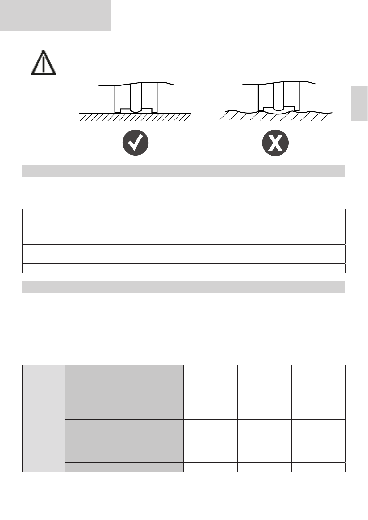
Operating manual
Welding consumables, particularly aluminium ones, must be performed on a at support surface.
5.2. SUPPORT PLATE THICKNESS DEPENDING ON THE STUD’S DIAMETER
With the exception of specic applications related to car bodywork (setting up pulling rings. etc.), the support sheet’s
thickness must not be less than one quarter of the consumable’s base diameter for steel, and half of the diameter for
aluminium.
Translation of the original
instructions
ARCPULL 350
EN
Examples (non-exhaustive list)
Parts to be welded
(in accordance with ISO 13918)
DD-type steel stud (M8) 8 mm 2 mm
PD-type steel stud (M6) 5.35 mm 1.3 mm
PS short-term stud AlMg (M8) 9 mm 2 mm
IS short-term stud (internally thread) (M5) 9 mm 2 mm
5.3. PROTECTING THE WELD POOL
Depending on the material to be welded, it may be necessary to protect the weld pool with a ceramic ferrule or gas
shielding.
The table below lists the recommended gas to use depending on the workpiece and its material. These gases are
used to make the weld stronger and correspond to the gas that should be used when the machine is operating in
SYNERGY mode (see section 8.1).
This table is given as an example, prior welding tests are recommended.
Material Welding consumables Ferrule
Aluminium
(Al, AlMg and
AlMgSi)
Low-carbon
steel (Fe)
Copper plated steel
(FeCu)
Stainless
steel
Aluminium pulling ring Impossible Argon
Studs, internally threaded studs Impossible ArHe 30% Impossible
Coarse threaded stud Impossible ArHe 30% Impossible
Steel pulling ring Impossible ArCO² 8% Possible
Studs, internally threaded studs OK ArCO² 8%
Stud, internal threaded stud, insulation
nail, coarse threaded stud
Studs, internally threaded studs
Stainless steel rivet-extraction rods
Base diameter Minimum sheet thickness
Gas shielding Without gas
(ceramic)
Impossible ArCO² 8%
Not recommended
Not recommended
ArCO² 2%
ArCO² 8%
shielding
Not recommended
Not recommended
Not recommended
Not recommended
Not recommended
41

Operating manual
Translation of the original
instructions
ARCPULL 350
Consumables to use
Stud consumable
kit (0
64591)
with
standard ceramic
ferrule support
adaptor (075979)
Consumable kit with th
chuck (064591)
Dicult-access stud support kit
(0708
13)
ARCPULL rivet consumable kit 1 350
24 kN (
064584
)
ARCPULL rivet consumable kit 2
5
0kN (073388)
readed
stud
350
If gas shielding is used, the gas-ow rate must be set between 12 -15 l/min.
Note: When welding aluminium, it is possible to use pure argon (Ar) instead of the 30% argon-helium mixture (ArHe30%).
Do not exceed 5 N.m when tightening a connection to the equipment’s gas inlet.
5.4. SELECTING WELDING ACCESSORIES
The type of welding tool to be used is determined by the type of consumable that needs to be welded (type, size and
material), as well as the welding position and the appropriate shielding (gas, gas-free or ceramic ferrule). The table
below provides guidance on selecting the appropriate tool.
Consumables Standard ceramic
ferrule support
adaptor (075979)
Parts to be welded
(in accordance with
ISO 13918)
Length of the part to
be welded
Max. base diameter
of the part to be
welded
PD, RD, DD studs
UD pin
From 25 -
65 mm
Flat (PA) if > 6 mm
Unrestricted if ≤ 6 mm
Consumable kit
with threaded stud
chuck (064591)
PD, RD, DD and
short-term PS studs
Internally threaded
short-term PS stud
UD and short-term
US pin
Insulation nail
From 25 -
30 mm
(100 mm for insulation nails)
Welding position (in accordance with ISO 6947)
Dicult-access
stud support kit
(070813)
PD, RD, DD and
short-term PS studs
Internally threaded
short-term PS stud
UD and short-term
US pin
Insulation nail
From 25 -
70 mm
(100 mm for insulation nails)
ARCPULL rivet
box 1 350 - 24 kN
(064584)
ARCPULL rivet
box 2 350 50kN
(PN. 073388)
Rivet-extraction rod Pulling ring
Unrestricted
Gun ring support
(059610)
42
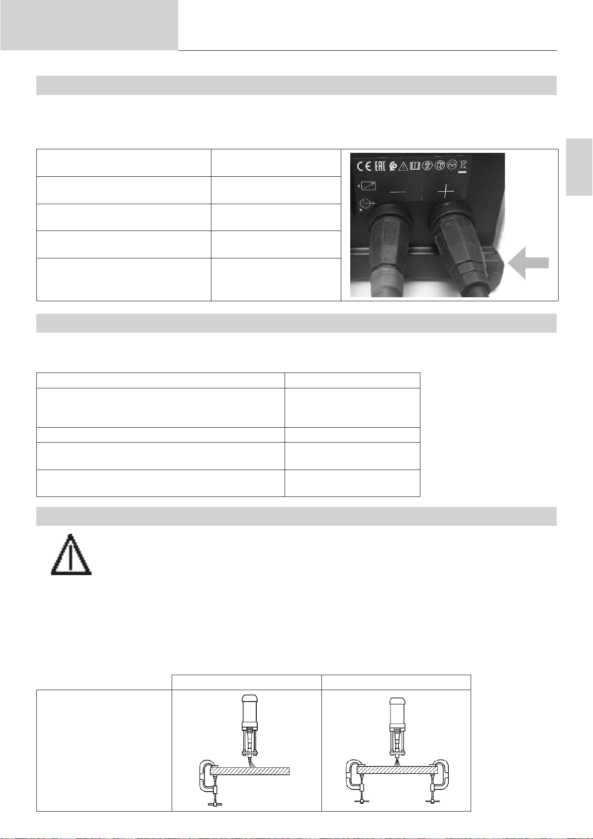
Operating manual
5.5. THE GUN’S POLARITY
The gun’s polarity has an impact on the welds’ quality.
Depending on the type and material of the part to be welded, connecting the gun’s positive dinse to the power
source’s + or - terminal is advised. Below is a table showing the suggested manufacturer-approved polarity choices.
Welding consumables Gun’s positive dinse
Aluminium pulling ring Power source’s negative
Steel pulling ring Power source’s positive
Rivet-extraction rod Power source’s negative
Stud, internally threaded stud, copper-plated steel insulation nail
Translation of the original
instructions
connection (red marker)
dinse connection (-)
dinse connection (+)
dinse connection (-)
Power source’s positive
dinse connection (+)
ARCPULL 350
-
+
EN
5.6. THE MACHINE’S WELDING RATE
The machine’s welding speed is automatically calculated to ensure that it does not exceed an eective current of 16
A from being drawn from the mains system. Depending on the type of consumable to be welded, and therefore the
current and welding time, the machine will have a longer or shorter rest time between two welds.
Weld part Pace
AlMg pulling ring (1.5 mm) on sheet metal with a
thickness of
1 mm
Rivet-extraction rod (Ø 5) 17/min
M6 copper-plated steel stud on sheet metal with a
thickness of 2 mm with gas shielding
M8 low-carbon steel stud on sheet metal with a
thickness of 8 mm with gas shielding
5.7. POSITIONING THE EARTH CLAMPS AND ARC BREAKAGES
Using an earthing clamp is essential, except for when setting up pulling rings for car-body repairs
(see section 7.1), where the earth connection is provided by the earthing rods (no. 4 - Fig. 2).
For welding parts up to Ø 5 mm, a single earth clamp will be sucient. Beyond that, an earth cable with two clamps must
be used to avoid extinguishing the arc.
19/min
8/min
4/min
As a reminder, the arc’s strength is proportionate to the welding current and may be inuenced by symmetrically positioning the earth clamps. A review of standard ISO 14555 on the positioning of earth clamps in relation to the welding
conguration.
Causes Solutions
Case 1: welding on at
sheet metal
43

Operating manual
Case 2: welding on sheet
metal with metal obstacles
Case 3: welding on IPN
beams
Translation of the original
instructions
ARCPULL 350
6. SETTING UP CONSUMABLES AND ADJUSTING THE GUN
Installing and adjusting consumables on the gun must be done:
- with the gun connected to the power source
- with the device switched on
- when the gun’s initialisation phase is completed (trigger pull request)
Appui gachette
6.1. CHANGING AND ADJUSTING THE LENGTH OF EARTHING PINS (PN. 059627)
Note 1: It is necessary to replace the earth rods if they have excessive markings on their ends or if they have been
bent as a result of dropping the gun.
Note 2: Using the ARCPULL Rivet Boxes 1 and 2 (P.N. 064584 and 073388), as well as the Dicult-Access Box (P.N.
070813), requires using the short pins supplied with the ARCPULL 350.
Loosen the locking knob (no. 3 - Fig. 2) so that the
earthing rods (no. 4 - Fig. 2) are fully extended from
the gun.
Then tighten the locking knob.
Unscrew the two front-panel screws and release the
cover slightly towards the front of the gun.
Slightly loosen the two rod-clamping screws.
44

Operating manual
Translation of the original
instructions
If changing the rods, remove them by pulling on
them, then replace them with new ones.
ARCPULL 350
Adjust the length of the gun’s earthing rods according to the type of welding consumable being used
(suitable for the distance between the end of the
earthing rods and the edge of the anges).
Consumables L (mm)
Gun ring support (059610) 120 mm
ARCPULL rivet kit 1 350 - 24 kN
55 mm
(064584)
ARCPULL rivet kit 3 350 - 50 kN
75 mm
(073388)
Stud support kit (M4 - M8) (068339) 120 mm
Ceramic adaptor (Ø 6 and Ø 8)
120 mm
(075979)
Dicult-access stud support box (M4 -
75 mm
M8) (070813)
Slightly loosen the two rod-clamping screws.
Replace the cover on the front of the gun and
tighten the two retaining screws.
EN
L
6.2. ADJUSTING A STUD SUPPORT/INSULATING NAIL SUPPORT
Note 1: The rivet-extraction stud support’s settings are dierent. This is detailed in the following sections: 6.4 and 6.5.
Note 2: When installing insulation nails, no adjustment is necessary. Insert the insulation nail up to the nail holder limit
stop.
6.2.1. ADJUSTING A WELDING STUD SUPPORT WITHOUT A CERAMIC FERRULE
The process for adjusting the stud support, as explained below, can be applied to all consumables except those welded
under ceramic ferrule protection (075979) and rivet extraction rods (see sections 6.4 and 6.5).
Adjusting
screw
Lock
nut
5 mm
45

Operating manual
Translation of the original
instructions
ARCPULL 350
1) Unscrew the stud support’s lock nut adjustment screw.
2) Insert the consumable into the stud support and adjust the screw so that the end of the consumable extends 5 mm
beyond the stud support.
3) Tighten the lock nut.
Note: If welding with a consumable and the welding area shows
marks made by the stud support adjust the stud-retaining
screws so that the consumable protrudes a little further out
of the stud support.
Marking
6.2.2. ADJUSTING A WELDING STUD SUPPORT WITH A CERAMIC FERRULE
Adjusting
screw
Lock
nut
15 mm
1) Unscrew the stud support’s lock nut adjustment screw.
2) Insert the consumable into the stud support and adjust the screw so that the end of the consumable extends 15 mm
beyond the stud support.
3) Tighten the lock nut.
6.3. USING THE PULLING RING POSITIONING ACCESSORY (PN. 059610)
Slightly unscrew the knurled nut (no. 2 - Fig 2) from
the gun’s drive shaft.
Position the pulling ring support until it stops and
then tighten the knurled nut.
Insert the pulling ring in the pulling ring support until
it can go in no further.
46

Operating manual
Translation of the original
instructions
6.4. USING THE ARCPULL 350 RIVET CONSUMABLE KIT 1 (350 - 24 KN) (PN. 064584)
Note: Prepare the earth pins as explained in section 6.1.
Completely remove the adjusting screw
from the stud support and insert a rivet-extraction rod until it can go in no further.
ARCPULL 350
Remove the knurled nut (no. 2 - Fig. 2)
from the gun’s drive shaft and screw in the
stud support.
Gently screw the gas shielding nozzle onto
the stud support, insert the stud support
until it can in no further and tighten the gas
shielding nozzle.
Assemble the rod-installation barrel with
the pad (pay attention to the positioning
of the holes) and t the entire assembly to
the gun’s rods.
EN
Loosen the gun’s locking knob (n°3 - Fig
2).
Adjust the barrel so that the tip of the
rivet-extraction rod protrudes slightly (0.5 2 mm) and tighten the gun’s locking knob.
0.5 - 2 mm
6.5. USING THE ARCPULL RIVET BOX 2 350 - 50 KN (P.N. 073388)
Note: Prepare the earth pins as explained in section 6.1.
Insert the stainless steel rivet-extraction
rod into the stud support and adjust the
stud-retaining screw to ensure that it
extends between 13.5 - 15 mm from the
stud support.
Remove the knurled nut (no. 2 - Fig. 2)
from the gun’s drive shaft and screw in the
stud support.
13.5 - 15 mm
47

Operating manual
Translation of the original
instructions
Gently screw the gas shielding nozzle onto
the stud support, insert the stud support
until it can in no further and tighten the gas
shielding nozzle.
Assemble the rod-installation barrel with
the pad (pay attention to the positioning
of the holes) and t the entire assembly to
the gun’s rods.
Loosen the gun’s locking knob (n°3 - Fig
2).
Adjust the barrel so that the tip of the
rivet-extraction rod protrudes slightly (0.5 2 mm) and tighten the gun’s locking knob.
ARCPULL 350
0.5 - 2 mm
6.6. USING THE GRIP 700 CERAMIC FERRULE (P.N. 068339)
Note 1: Prepare the earth pins as explained in section 6.1.
Note 2: Prepare the stud support as explained in section 6.2.
Remove the knurled nut (no. 2 - Fig.
2) from the gun’s drive shaft and
screw in the stud support.
Gently screw the gas shielding
nozzle onto the stud support, insert
the stud support until it can in no
further and tighten the gas shielding
nozzle.
Conguration 1 Conguration 2
48

Operating manual
Translation of the original
instructions
Assemble the gas shielding cover and the pad depending on the
conguration of the selected tool (pay
attention to the position of the holes).
Fit the entire assembly to the gun’s
rods.
ARCPULL 350
EN
Loosen the gun’s locking knob (n°3 Fig 2).
Adjust the pad and gas shielding
cover assembly so that the end of the
part to be welded protrudes slightly
(0.5 - 2 mm) and tighten the gun’s
locking knob.
0.5 - 2 mm
0.5 - 2 mm
6.7. USING THE CERAMIC FERRULE ADAPTOR (P.N. 075979)
Note: The Stud Holder Box 350 (P.N. 068339) is required to use the ceramic ferrule adaptor.
6.7.1. SELECTING A CERAMIC FERRULE SUPPORT
Choose the appropriate ceramic ferrule for the consumable to be welded (type and diameter). Note: the ISO 13918
standard advises on choosing ferrules according to the type of parts to be welded.
Consumable types Studs and ceramic ferrules for arc
Designation Description according to ISO 13918
Complete internally threaded stud
Pin
DD
UD
stud welding according to ISO 13918
UF
Partial threaded stud PD PF
Reduced-shaft stud RD RF
The ceramic ferrule support must be chosen according to the ferrule’s diameter.
Support too large
Adjusted support
49

Operating manual
Translation of the original
instructions
6.7.2. PROCEDURE FOR CHANGING THE CERAMIC ADAPTOR
Unscrew the two screws and remove the ceramic support from the adaptor.
Reposition the correct support onto the adaptor (grooves
facing outwards) and tighten the two screws.
ARCPULL 350
6.7.3. FITTING CONSUMABLES TO THE GUN
Repeat the rst two stages of the procedure for tting the
stud support to the gun’s drive shaft.
Fit the adaptor to the end of the rods and tighten the two
rod-clamping screws.
Position the ceramic ferrule onto the adaptor.
Loosen the gun’s locking knob (n°3 - Fig 2).
Adjust the assembly so that the end of the part to be
welded protrudes slightly (0.5 - 2 mm) from the tip of the
ferrule.
Tighten the gun’s locking knob.
6.8. DIFFICULT-ACCESS STUD HOLDER BOX (P.N. 070813)
0.5 - 2 mm
Note 1: Prepare the earth pins as explained in section 6.1.
Note 2: Prepare the stud support as explained in section 6.2.
Note 3: Choose the appropriate gun to suit the material of the consumable to be welded. The engraved barrel of a
is not suitable for welding aluminium parts.
50

Operating manual
Translation of the original
instructions
Remove the knurled nut (no. 2 - Fig. 2) from
the gun’s drive shaft and screw in the stud
support.
Gently screw the gas shielding nozzle onto
the stud support, insert the stud support
until it can in no further and tighten the gas
shielding nozzle.
Assemble the rod-installation barrel with
the pad (pay attention to the positioning of
the holes) and t the entire assembly to the
gun’s rods.
ARCPULL 350
EN
Loosen the gun’s locking knob (n°3 - Fig 2).
Adjust the barrel so that the tip of the rivet-extraction rod protrudes slightly (0.5 - 2
mm) and tighten the gun’s locking knob.
0.5 - 2 mm
7. HANDLING THE GUN
7.1. WELDING PULLING RINGS
1. Attach the pulling ring holder (see section 6.3).
2. Strip away the paint where the welding is to be carried out.
3. Select the correct synergy for the pulling ring to be welded.
4. Connect the gun’s negative dinse connection to the welding machine (do
not use a earthing clamp).
5. To use in MANUAL mode: Set the digital «ex» spring to OFF (see section
8.4.2).
51

Operating manual
6. Insert a pulling ring into the ring support.
7. Unlock the earthing rods using the locking knob.
8. Position the gun on the sheet and bring the pulling ring into contact with
the sheet. As soon as the gun beeps or the contact LED (blue) indicator light
comes on, secure the earthing rods using the locking knob.
9.
Pull the trigger while holding the gun rmly
against the support plate.
10. Once the welding process is complete, unlock the locking knob to release
the earthing rods and lift the gun to release the pulling ring.
Every 30 weldings of pulling rings, the message «Check rods» appears on
the screen. Check the end of the ground rods (n°4 gure 2). If they show weld
marks, sand them lightly with abrasive paper to restore their electrical contact.
Translation of the original
instructions
ARCPULL 350
Press to conrm and reset the counter.
Note : This function is not activated when an ArcPull 700 gun is used (see §2.3))
7.2. WELDING CONSUMABLES (EXCLUDING PULLING RINGS)
1. Fit and adjust the welding consumable (gas shielding, ceramic adaptor, ri-
vet-extraction consumable, etc.).
2. Position the earthing clamps on the support sheet so that they are equidistant
from the consumable’s welding area (see section 5.7). Earthed parts must be
stripped, cleaned and grease-free.
3. Select the appropriate synergy, or, if operating in MANUAL mode: Set the digi-
tal «ex» spring to OFF (see section 8.4.2).
4. Position the gun on the sheet metal. As soon as the gun beeps, or its contact
LED indicator light (blue) lights up, press the gun’s trigger so that the accessory is
correctly placed onto the sheet metal (there must be no tilting).
5.
Pull the trigger while holding the gun rmly
against the support plate.
6. When the welding process is complete, lift the gun to release the electrode
(pulling ring or threaded stud).
52

Operating manual
8. HOW THE DEVICE WORKS
Fig 3: Overview of the machine’s keypad
2
Translation of the original
instructions
ARCPULL 350
1
EN
4
3
6
1 Display screen
2 Left + button
3 Left - button
4 5 Right + button
5 6- Right - button
6 Main Menu/Enter button
7 Return/Cancel button
The product has both SYNERGY and MANUAL operating modes as well as a system for saving and recalling weld
congurations.
When the ARCPULL 350 is switched on, it will return to whichever operating mode it was in when it was last switched
o.
Changing the mode (MANUAL or SYNERGY) and retrieving previous welding congurations is done via the main menu.
8.1. WELDING IN SYNERGY MODE
7
5
In SYNERGY mode, the device automatically determines the height of the arc as well as the dierent welding phases’
times and currents. Therefore, a synergy is determined by the type of part to be welded, its material, its gas shielding,
its size and the supporting sheet.
The type of gas to use is shown on the display screen. If the welding gun has the wrong polarity, a message will ap-
pear on the display and the fault LED indicator light (red) on the gun will ash.
The dierent welding settings are determined for the attachment parts sold by GYS.
These synergies (pre-installed user settings) are still valid for longer attachments (see section 5.4) as
long as they are the same type and material as those sold by GYS in accordance with ISO 13918).
Aluminium consumable synergies (excluding those for pulling rings) were determined on support sheets preheated to
50 - 60°C.
A few test welds should be made on a spare support plate beforehand to ensure that the welds will hold.
53

Operating manual
message
message
Translation of the original
instructions
ARCPULL 350
The SYNERGY mode main screen will display:
1.) The consumable’s material: AlMg, Fe, etc.
2.) The type of weld pool protection: a ferrule, without gas shielding or using the recommended gas type
3.) The part to be welded’s icon
4.) The thickness of the sheet metal to which the part will be welded
5.) «Prog» followed by a number will be displayed when a welding conguration has been saved (see section 8.4.3).
6.) A message area indicating the machine’s status (see section 8.3)
1
5
FeCu Prog 3
2
3
8.1.1. TYPE OF PART TO BE WELDED
From the synergy displayed on the screen, dened by the part type (3), its material (1) and its shielding (2), it is possible to only modify the part’s size (M4 or M5, etc.) without having to go through the setting menu by pressing G+ and
G- (see section 8.4.1).
Consumable
Pulling ring
Rivet-extraction rod
Internal
thread stud
Threaded
stud (and
unthreaded
stud)
Insulation nail
ArCo_8%
M8 4.0
zone de
zone de
6
Name of the electrode
in the synergic setting
menu
Ring
Rod When a rivet-extraction synergy is selected,
Insert Synergies associated with short-cycle,
Stud Associated synergies:
Nail
Icons
4
Comments
Pressing G+ and G- will scroll through all
the pulling ring synergies stored in the machine’s memory. The material (1) and gas
shielding (2) are automatically updated.
the thickness display (4) changes automatically and indicates the diameter in millimetres of the rivet head to be extracted.
internally threaded studs (type US).
The Mx value corresponds to the stud’s
internal thread.
• Low-carbon steel (Fe) and stainless
steel: threaded stud type DD
• Copper-plated steel (FeCu): short-cycle
threaded stud tpye PS
Short-cycle unthreaded stud type US
Visual
54
Coarse
thread stud
Clip The Tx value corresponds to the thread
diameter of the clip.

Operating manual
message
8.1.2. THE SUPPORT PLATE’S THICKNESS
Thickness displayed in millimetres.
To increase or decrease the thickness of the sheet to which the attachment will be welded, press the D+ and D- keys.
The thickness ranges that can be selected are linked to the type, size and material of the workpiece to be welded.
Translation of the original
instructions
ARCPULL 350
If the sheet’s thickness is less than that indicated on the screen, the support sheet may become deformed during the
welding process.
When the workstation displays , the sheet’s thickness is suciently high that the synergy’s welding parameter
settings are no longer aected.
If this symbol does not appear, then the sheet metal’s maximum thickness has been reached. Beyond this thickness, it
is no longer possible to guarantee that the consumable can be welded.
Note 1: When a rivet-pulling rod synergy is selected, the thickness changes ( icon) and corresponds to the rivet
head’s diameter in millimetres.
Note 2: When switching from SYNERGY to MANUAL mode, all welding parameters (currents, times and heights, etc.)
associated with the synergy are automatically transferred over to MANUAL mode. This makes it possible to
ne-tune the machine’s settings if the selected synergy does not achieve the expected result (over- or under-en-
ergised welding).
8.2. WELDING IN MANUAL MODE
In MANUAL mode, the consumables’ times, current, lift height and digital spring activation are to be set by the user.
The MANUAL mode main screen will display:
1.) The arc time in milliseconds (see section 4)
2.) The arc current (see section 4)
3.)»Prog» followed by a number will be displayed when a welding conguration has been saved (see section 8.4.3)
4.) A message box showing the product’s status (see section 8.3)
EN
3
Prog 4
t ms I A
1
100 350
zone de
4
To increase or decrease the arc time ( value), press the G+ and G- keys.
To increase or decrease the arc current ( value), press keys D+ and D-.
To change the other manual welding parameters (welding current and timings), please refer to the chapter entitled
«Manual Settings».
2
55

Operating manual
Menu Principal
8.3. LIST OF MESSAGES DISPLAYED AT THE BOTTOM OF THE WELDING SCREEN
Message Description
Gun disconnected There is no gun connected to the machine.
Dinse disconnected The gun’s positive dinse is not connected to the power source (no.6 - Fig. 2).
Inverted dinse (only in SYNERGY mode). The dinse’s polarity is the opposite of that required by the sy-
nergy.
Ready After the resting cycle is complete, the product is available for welding.
Movement only The machine has detected that the trigger was pulled without a consumable being in
contact with the support plate. The gun then carries out a mechanical movement on its
own, the power source is not switched on.
Contact The welding machine has detected that a consumable is in contact with the support sheet.
If welding is done under gas shielding, the gas solenoid valve will open for Pre-Gas.
Welding Current welding cycle.
Welding nished Welding cycle nished.
Pre-Gas Displayed when the trigger is pulled before the Pre-Gas time has nished (see section
8.4.4). For the welding to take place, it is necessary to remain in position (with the consu-
mable still in contact with the support sheet) and to wait for the end of the Pre-Gas phase.
Contact lost Displayed when contact between the consumable and the support sheet has been lost
before the Pre-Gas time has nished.
Arc breakage
Translation of the original
instructions
An arc break occurred during the welding cycle.
Check the weld is necessary.
ARCPULL 350
Gun lift Displayed at the end of the welding cycle if the gun is still in contact with the consumable.
8.4. MAIN MENU
To access the main menu from both SYNERGY and MANUAL mode, press the button.
> Réglages
Mode Synergique
Programmes
Configuration
Press the G+ and G- keys to move the cursor. Select the item by pressing the button.
• ‘Settings’ will access the welding settings (synergic or manual)
• MANUAL mode / SYNERGY mode will change the device’s welding mode
• The «Programs» menu accesses the user’s saved or recalled welding congurations
• «Conguration» provides access to the appliance’s advanced settings (languages, gas management and data,
etc.)
Press the return button to return to the welding screen.
56

Operating manual
8.4.1. SYNERGY MODE’S SETTINGS MENU
When the unit is operating in SYNERGY mode, the settings menu allows you to select the type of consumable to be
welded as well as its size, material and gas shielding type.
In SYNERGY mode, the settings are selected in order from top to bottom:
1 - Electrode consumable type: studs, nails and rings, etc.
2 - Electrode consumable size: Mx or Øx, etc.
3 - Electrode consumable material: Fe, FeCu or Al, etc.
4 - Gas shielding type: Ferrule, with or without gas shielding.
Note: When the welding is to be done under gas shielding, the gas displayed is the one that is recommended to
guarantee the durability of the weld (see section 5.3). If this is not possible, switching to MANUAL mode may be
necessary (see section 8.2).
Translation of the original
instructions
ARCPULL 350
Réglages Synergie
> Electrode > Goujon
Setting order
EP. élec. M8
Matériau FeCu
Gaz ArCo8%
EN
Press the left-side + and - keys to move the left cursor and press the right-side + and - keys to change the values of
each item.
Pressing the Menu/Enter button will conrm the SYNERGY mode settings and return the machine to the SYNERGY
mode welding screen.
Press the return button to discard the settings and return to the main menu.
8.4.2. MANUAL MODE’S SETTINGS MENU
The settings menu allows all relevant welding parameter settings to be individually adjusted when the unit is operated
in MANUAL mode.
Réglages Manuel
1
2
6 & 7
5
Ressort > ON
3 4
Pressing the left-side + and - keys highlights the selected parameter setting. Pressing the right-side + and - buttons
will change the value of this setting.
1 - Digital ‘ex’ spring:
• Releases (ON) or locks (OFF) the electrode holder’s drive shaft when the consumable comes into contact with the
support plate.
• Activating this function is recommended for all consumables, except for pulling rings.
57

Operating manual
Programmes
2 - Ignition:
• Can be adjusted between -2 - +8. This directly aects the device’s power converter setpoint.
• The default value (0) ensures the best possible ignition without the risk of breaking the arc when the attachment is
lifted whilst also limiting the short-circuit current.
• Increase the ignition slightly if the arc repeatedly breaks.
3 - Cleaning: Set the time (in milliseconds) and cleaning current. See section 4 for further details.
4 - Arc: Set the time (in milliseconds) and the arc current. See section 4 for further details.
5 - Attaching:
• Can be adjusted between -2 - +8. This directly aects the device’s power converter setpoint.
• The default value (0) ensures the best possible attachment of the electrode to the support plate.
6 - Height:
• The consumable’s lift height (in millimetres) during the welding process.
• If the height is too great, the arc will be extinguished more frequently (see section 5.7). If the height is too low, the
weld may be short-circuited due to the stud’s tip being warped during the welding process.
7- Force :
• Adjustable from 0 to 4. Directly aects the plunge force of the insert in the molten bath (forging).
• At 0 the plunge force is zero, at 4 it is maximum. In the case of a weld that does not respect the maximum sheet
thickness diameter ratio (see §4.2). It may be necessary to reduce this force to avoid piercing it.
Translation of the original
instructions
ARCPULL 350
Pressing the Menu/Enter button will conrm the welding settings and return the machine to the MANUAL mode
welding screen.
Press the return button to discard the settings and return to the main menu.
8.4.3. PROGRAM MENU
Up to 99 dierent welding congurations, in both SYNERGY and MANUAL mode, can be saved to the machine.
> Sauvegarder
Rappeler
Effacer
Effacer tout
Press the left-side + and - keys to move the left cursor and select one of the four functions in the program menu
(Save, Recall, Delete and Delete All).
Pressing the button opens the highlighted function.
Press the return button to go back to the main menu.
When a welding conguration is saved or recalled, «Prog» followed by the program number is displayed on the welding screen (in both SYNERGY and MANUAL mode).
58

Operating manual
Configuration
Info
Reset machine
pour valider
8.4.4. CONFIGURATION MENU
Translation of the original
instructions
ARCPULL 350
> Pregaz > 400ms
Postgaz 400ms
Langue FR
Compteurs
Reset machine
Press the left-side + and - keys to move the left cursor (Pre-Gas, Post-Gas, Language, Machine reset and Info.).
When the Pre-gas, Post-gas or language options are highlighted, press the right-side + and - keys to change their value.
Test Settings range Comments
Pre-Gas No Gas between 0.2 - 3 s. Setting the Pre-Gas time to at least 0.4 s is recommended for gas-
shielded welding.
Post-Gas No Gas between 0.2 - 3 s. Setting the Post-Gas time to at least 0.4 s is recommended for wel-
ding under gas shielding.
Languages FR, EN, DE, NL, ES, IT and
RU.
EN
Press the return button to go back to the main menu.
8.4.4.1. Counts
When «Counts» is selected, the display shows :
- the day counter: number of correctly made welds since the product was switched on. This counter is reset to zero
when the product is restarted
- the total counter: number of welds carried out correctly by the product since it left the factory.
8.4.4.2. Resetting the Machine
When ‘Machine Reset’ is selected from the conguration menu, pressing the Menu/Enter button will bring up the
machine’s reset submenu.
:3sec
Hold down the Menu/Enter button for three seconds to conrm resetting the device.
Press the return button to go back to the settings menu and to cancel resetting the device.
Resetting the ARCPULL 350 will clear all welding settings from the program menu, switch the product
back to French and the Pre-Gas and Post-Gas times will automatically return to 0.4 s.
59

Operating manual
Translation of the original
instructions
ARCPULL 350
8.4.4.3. Information Panel
Info machine
Soft gene V3.0
Hard gene V1.0
Pistolet 200-350
Soft pistolet V3.0
Hard pistolet V7.0
The information panel shows the machine’s software and hardward version numbers and, if connected, the type of
gun attached (200-350, 700).
9. ERROR MESSAGES, FAULTS, CAUSES AND SOLUTIONS
This equipment has a fault monitoring system. An error message will be shown on the display screen in the event of a fault.
Error message Meaning Causes Solutions
The device’s thermal
protection.
Exceeding the duty cycle. Wait until the message has
disappeared before resuming
welding.
DEFAUT THERMIQUE
Mains voltage fault. Mains voltage out of range
or missing a phase.
Have your electrical system
checked by an authorised per-
son. Reminder: the machine is
designed to operate on a single-
DEFAUT SECTEUR
phase, 208-240 V AC, 50/60 Hz
network.
Keypad fault. A key on the keypad has
been pressed when the pro-
Have the keypad checked by a
qualied technician.
duct is switched on.
TOUCHE APPUYEE
Gun communication fault. The communication sys-
tem between the gun and
the machine is not working
Reconnect the gun and turn
the welding machine o and on
again.
properly.
DEFAUT COM.
If the fault persists, have the
product checked by a qualied
technician.
The gun’s thermal protection.
Exceeding the duty cycle. Wait until the message has
disappeared before resuming
welding.
60
THERMISCHER FEHLER
SONDE DECONNECTEE
Gun motor fault. The gun’s mechanism is
blocked.
Reconnect the gun and turn
the welding machine o and on
again.
If the fault persists, have the gun
checked by a qualied technician.

Operating manual
Translation of the original
instructions
ARCPULL 350
Wire temperature-sensor
fault.
DEFAUT MOTEUR
The temperature sensor is
disconnected.
Have the keypad checked by a
qualied technician.
WARRANTY CONDITIONS (FRANCE)
The warranty covers all defects or manufacturing faults for two years from the date of purchase (parts and labour).
The warranty does not cover:
• Any other damage caused by transport.
The parts’ normal wear and tear (e.g : electrode holders and earthing rods, etc.).
• Incidents caused by misuse (misfeeding the wire, dropping or dismantling the machine).
• Environmental failures (pollution, rust and dust, etc.).
In the event of a breakdown, return the appliance to your distributor along with:
- dated proof of purchase (receipt or invoice, etc.).
- a note explaining the breakdown.
EN
61

Betriebsanleitung
Warnungen - Sicherheitsregeln ����������������������������������������������������������������������������������������������������������������������������������63
1.
Übersetzung der
Originalbetriebsanleitung
ARCPULL 350
2. Beschreibung des Geräts �����������������������������������������������������������������������������������������������������������������������������������������������67
3. Versorgung und Inbetriebnahme �������������������������������������������������������������������������������������������������������������������������������69
3,1 Anschluss an einen Generator ��������������������������������������������������������������������������������������������������������������������������������������������� 69
3,2 Verwendung eines Verlängerungskabels ������������������������������������������������������������������������������������������������������������������������������� 69
3,3 Anschluss der Pistole an den Generator�������������������������������������������������������������������������������������������������������������������������������� 69
3,4 Aktualisierung des Geräts���������������������������������������������������������������������������������������������������������������������������������������������������� 70
4. Verfahren zum Schweißen eines Aufsatzstücks mit Hubzündung �������������������������������������������������������������70
5. Stiftmodell und Schutz des Schmelzbades ������������������������������������������������������������������������������������������������������������70
5,1 Oberächenbeschaenheit des Trägerteils und Abbeizen ������������������������������������������������������������������������������������������������������� 71
5,2 Dicke des Trägerblechs in Abhängigkeit vom Durchmesser des Stifts �������������������������������������������������������������������������������������� 71
5,3 Schutz des Schmelzbads ���������������������������������������������������������������������������������������������������������������������������������������������������� 71
5,4 Auswahl des Schweißzubehörs ������������������������������������������������������������������������������������������������������������������������������������������� 72
5,5 Polarität der Pistole �����������������������������������������������������������������������������������������������������������������������������������������������������������73
5,6 Geschwindigkeit des Schweißgeräts ������������������������������������������������������������������������������������������������������������������������������������� 73
5,7 Positionierung der Masseklemmen und des Lichtbogenschachts �������������������������������������������������������������������������������������������� 73
6. Installation von Zubehör und Einstellung der Pistole �������������������������������������������������������������������������������������74
6,1 Austausch und Anpassung der Länge der Massenanschluss-Stifte (Ref. 059627) ���������������������������������������������������������������������74
6,2 Einstellung eines Stifthalters/Isoliernagelhalters�������������������������������������������������������������������������������������������������������������������� 75
6�2�1 Einstellung eines Stifthalters für die Schweißung ohne Keramikhülse ������������������������������������������������������������������������������� 76
6�2�2 Einstellung eines Stifthalters für die Schweißung mit Keramikhülse ���������������������������������������������������������������������������������76
6,3 Verwendung des Zubehörs zur Installation des Zugrings (Ref. 059610) ���������������������������������������������������������������������������������� 76
6,4 Verwendung des Koers ArcPull Rivet Box1 350 – 24 kN (Ref. 064584) ���������������������������������������������������������������������������������� 77
6,5 Verwendung des Koers ArcPull Rivet Box2 350 – 50 kN (Ref. 073388) ���������������������������������������������������������������������������������� 77
6,6 Verwendung des Koers Stud Hold Box 350 (Ref. 068339) ���������������������������������������������������������������������������������������������������� 78
6,7 Verwendung des Adapters für Keramikhülse (Ref. 075979) ����������������������������������������������������������������������������������������������������79
6�7�1 Auswahl des Keramikhülsenhalters �������������������������������������������������������������������������������������������������������������������������������79
6�7�2 Verfahren zum Wechseln des Keramikadapters ��������������������������������������������������������������������������������������������������������������80
6�7�3 Anbringen des Zubehörs auf der Pistole ������������������������������������������������������������������������������������������������������������������������ 80
6,8 Verwendung der Koer ArcPull 350 Dicult Access (Ref. 070813) ������������������������������������������������������������������������������������������ 81
7. Manipulation der Pistole �����������������������������������������������������������������������������������������������������������������������������������������������82
7,1 Schweißen von Zugringen ��������������������������������������������������������������������������������������������������������������������������������������������������� 82
7,2 Schweißen von Aufsatzstücken außerhalb der Zugringe �������������������������������������������������������������������������������������������������������� 82
8. Funktionsweise des Geräts ������������������������������������������������������������������������������������������������������������������������������������������83
8,1 Schweißen im Synergie-Modus �������������������������������������������������������������������������������������������������������������������������������������������� 83
8.1.1 Art der zu schweißenden Stücke ����������������������������������������������������������������������������������������������������������������������������������� 84
8.1.2 Stärke des Trägerblechs ����������������������������������������������������������������������������������������������������������������������������������������������� 85
8,2 Schweißen im Modus Manuell ��������������������������������������������������������������������������������������������������������������������������������������������� 85
8,3 Liste der Meldungen, die am unteren Rand des Schweißbildschirms angezeigt werden ����������������������������������������������������������� 86
8,4 Hauptmenü ������������������������������������������������������������������������������������������������������������������������������������������������������������������������ 86
8.4.1 Einstellmenü im Synergie-Modus ����������������������������������������������������������������������������������������������������������������������������������87
8.4.2 Einstellmenü im Modus Manuell ������������������������������������������������������������������������������������������������������������������������������������ 87
8.4.3 Menü Programme �������������������������������������������������������������������������������������������������������������������������������������������������������� 88
8.4.4 Menü Konguration �����������������������������������������������������������������������������������������������������������������������������������������������������89
9. Fehlermeldung, Anomalien, Ursachen, Lösungen ����������������������������������������������������������������������������������������������� 90
Schaltplan und Ersatzteile �������������������������������������������������������������������������������������������������������������������������������������������92
10.
10,1 Stromquelle ����������������������������������������������������������������������������������������������������������������������������������������������������������������������� 92
10,2 Pistole ������������������������������������������������������������������������������������������������������������������������������������������������������������������������������ 95
Technische Eigenschaften ��������������������������������������������������������������������������������������������������������������������������������������������97
11.
62

Betriebsanleitung
Übersetzung der
Originalbetriebsanleitung
ARCPULL 350
1. WARNUNGEN - SICHERHEITSREGELN
ALLGEMEINER HINWEIS
Die Missachtung dieser Bedienungsanleitung kann zu schweren Personen- und Sachschäden führen.
Nehmen Sie keine Wartungsarbeiten oder Veränderungen an dem Gerät vor, die nicht in der Anlei-
tung genannt werden.
Der Hersteller haftet nicht für Verletzungen oder Schäden, die durch unsachgemäße Handhabung dieses Geräts entstanden sind.
Bei Problemen oder Unsicherheiten wenden Sie sich bitte an eine Person, die für die ordnungsgemäße Durchführung der Installation qualiziert ist.
UMGEBUNG
Dieses Gerät darf nur dazu verwendet werden, Schweißarbeiten innerhalb der auf dem Typenschild und/oder in der Anleitung angegebenen
Grenzbereichen durchzuführen. Beachten Sie die Sicherheitsanweisungen. Der Hersteller ist nicht für Schäden, bei fehlerhaften oder gefährlichen
Verwendung, verantwortlich.
Das Gerät muss in einem Raum betrieben werden, der frei von Staub, Säuren, brennbaren Gasen oder anderen korrosiven Stoen ist. Das Gleiche
gilt für seine Lagerung. Achten Sie bei der Verwendung auf eine gute Belüftung.
Betriebstemperatur:
Verwendung zwischen -10 und +40°C (+14 und +104°F).
Lagertemperatur zwischen -20 und +55°C (-4 und 131°F).
DE
Luftfeuchtigkeit:
Kleiner oder gleich 50 % bei 40 °C (104 °F).
Kleiner oder gleich 90 % bei 20 °C (68 °F).
Meereshöhe:
Das Gerät ist bis in einer Höhe von 1.000 m über Meer (3280 Fuß) einsetzbar.
PERSONENSCHUTZ
Lichtbogenschweißen kann gefährlich sein und zu schweren - unter Umständen auch tödlichen - Verletzungen führen.
Beim Schweißen sind Personen einer gefährlichen Quelle von Hitze, Lichtbogenstrahlung, elektromagnetischen Feldern (Vorsicht bei Trägern von
Herzschrittmachern), der Gefahr eines Stromschlags, Lärm und Gasen ausgesetzt.
Schützen Sie daher sich selbst und andere. Beachten Sie unbedingt die folgenden Sicherheitshinweise:
Die Lichtbogenstrahlung kann zu schweren Augenschäden und Hautverbrennungen führen. Die Haut muss durch geeignete
trockene Schutzbekleidung (Schweißhandschuhe, Lederschürze, Sicherheitsschuhe) geschützt werden.
Tragen Sie elektrisch- und wärmeisolierende Handschuhe.
Verwenden Sie eine Maske oder eine Schutzbrille mit einer Tönung zwischen 5 und 9. Schützen Sie Ihre Augen bei Reinigungsarbeiten.
Kontaktlinsen sind ausdrücklich verboten!
Schirmen Sie den Schweißbereich bei entsprechenden Umgebungsbedingungen durch Schweißvorhänge ab, um Dritte vor
Lichtbogenstrahlung, Schweißspritzen, usw. zu schützen.
In der Nähe des Lichtbogens bendliche Personen müssen ebenfalls auf Gefahren hingewiesen werden und mit der nötigen
Schutzausrüstung ausgerüstet werden.
Verwenden Sie einen Lärmschutzhelm, wenn der Schweißprozess einen Geräuschpegel über dem zulässigen Grenzwert erreicht
(dasselbe gilt für alle Personen im Schweißbereich).
Halten Sie mit den ungeschützten Händen, Haaren und losen Kleidungstücken ausreichenden Abstand von beweglichen Teilen
(Lüfter, Elektroden).
ACHTUNG! Das Werkstück ist nach dem Schweißen sehr heiß! Seien Sie daher im Umgang mit dem Werkstück vorsichtig, um
Verbrennungen zu vermeiden. Bei Wartungsarbeiten am pistole muss sichergestellt werden, dass dieser ausreichend abgekühlt ist,
indem vor der Arbeit mindestens 10 Minuten gewartet wird.
Der Arbeitsbereich muss zum Schutz von Personen und Geräten vor dem Verlassen gesichert werden.
63

Betriebsanleitung
Übersetzung der
Originalbetriebsanleitung
ARCPULL 350
SCHWEISSRAUCH/-GAS
Beim Schweißen entstehen Rauchgase bzw. toxische Dämpfe. Es muss für eine ausreichende Belüftung gesorgt werden, und
manchmal ist eine Luftzufuhr erforderlich. Eine Frischluftmaske kann bei unzureichender Belüftung eine Lösung sein.
Überprüfen Sie die Wirksamkeit der Luftansaugung, indem Sie diese anhand der Sicherheitsnormen überprüfen.
Achtung: Das Schweißen in kleinen Räumen erfordert eine Überwachung des Sicherheitsabstands. Außerdem kann das Schweißen von bestimmten
Materialien, die Blei, Cadmium, Zink, Quecksilber oder Beryllium enthalten, besonders schädlich sein. Vor dem Schweißen sollten Sie die Elemente
entfetten.
Die Flaschen müssen in oenen oder gut belüfteten Räumen gelagert werden. Sie sollten sich in einer aufrechten Position benden und an einem
Ständer oder auf einem Wagen gehalten werden.
Es darf nicht in der Nähe von Fett oder Farbe geschweißt werden.
BRAND- UND EXPLOSIONSGEFAHR
Sorgen Sie für ausreichenden Schutz des Schweißbereiches. Der Sicherheitsabstand für Gasaschen (brennbare Gase) und
andere brennbare Materialien beträgt mindestens 11 Meter.
Brandschutzausrüstung muss im Schweißbereich vorhanden sein.
Beachten Sie, dass die beim Schweißen entstehende heiße Schlacke, Spritzer und Funken eine potentielle Quelle für Feuer oder Explosionen
darstellen.
Halten Sie einen Sicherheitsabstand zu Personen, entammbaren Gegenständen und Druckbehältern ein.
Das Schweißen in geschlossenen Behältern oder Rohren ist zu untersagen und wenn diese geönet sind, müssen diese von brennbaren oder
explosiven Stoen (Öl, Kraftsto, Gasrückstände etc.) entleert werden.
Schleifarbeiten dürfen nicht auf die Schweißstromquelle oder auf brennbare Materialien gerichtet werden.
UMGANG MIT GASFLASCHEN
Austretendes Gas kann in hoher Konzentration zum Erstickungstod führen. Sorgen Sie daher immer für eine gut belüftete Arbeits-
und Lagerumgebung.
Der Transport muss auf sichere Art und Weise erfolgen: Flaschen geschlossen und die Schweißstromquelle ausgeschaltet.
Lagern Sie die Gasaschen ausschließlich in vertikaler Position und sichern Sie sie z. B. mithilfe eines entsprechenden
Gasaschenfahrwagens gegen Umkippen.
Verschließen Sie die Gasaschen nach jedem Schweißvorgang. Achten Sie auf Temperaturschwankungen und Sonneneinstrahlung.
Die Flasche darf nicht in Kontakt mit einer Flamme, einem Lichtbogen, einem Brenner, einer Erdungsklemme oder einer anderen Wärme- oder
Glühquelle kommen.
Halten Sie die Flasche von Strom- und Schweißkreisen fern und schweißen Sie niemals in ihre unmittelbarer Nähe.
Vorsicht beim Önen des Flaschenventils: Halten Sie den Kopf von der Armatur weg und vergewissern Sie sich, dass das verwendete Gas sich für
den Schweißprozess eignet.
ELEKTRISCHE SICHERHEIT
Das verwendete Stromnetz muss zwingend geerdet sein. Verwenden Sie nur die empfohlenen Sicherungen.
Das Berühren stromführender Teile kann tödliche elektrische Schläge und schwere Verbrennungen bis zum Tod verursachen.
Berühren Sie niemals gleichzeitig Teile innerhalb und außerhalb der Stromquelle (Brenner, Zangen, Kabel, Elektroden), da diese mit dem
Schweißstromkreis verbunden sind und Stromführen können.
Bevor Sie die Schweißstromquelle önen, müssen Sie sie unbedingt vom Netz trennen und paar Minuten warten, damit alle Kondensatoren entladen
werden.
Berühren Sie niemals gleichzeitig den Brenner oder den Elektrodenhalter und die Erdungsklemme.
Ausschließlich qualiziertes und geschultes Fachpersonal darf beschädigte Kabel und Brenner austauschen. Dimensionieren Sie den Querschnitt der
Kabel entsprechend der Anwendung. Tragen Sie zur Isolierung beim Schweißen immer trockene Kleidung in gutem Zustand. Achten Sie unabhängig
der Umgebungsbedingungen stets auf isolierendes Schuhwerk.
CEM-KLASSE DES GERÄTS
Der Norm IEC 60974-10 entsprechend, wird dieses Gerät als Klasse A Gerät eingestuft und ist somit für den industriellen und/
oder professionellen Gebrauch geeignet. An diesen Standorten kann es aufgrund von leitungsgebundenen und abgestrahlten
Hochfrequenzstörungen zu potenziellen Störungen bei der Gewährleistung der elektromagnetischen Verträglichkeit kommen.
Unter der Voraussetzung, dass die Impedanz des öentlichen Niederspannungsnetzes am gemeinsamen Koppelpunkt kleiner
als Zmax = 0,20 Ohm ist, entspricht dieses Gerät der Norm IEC 61000-3-11 und kann an öentliche Niederspannungsnetze
angeschlossen werden. Der Installateur oder Nutzers des Geräts ist zuständig dafür, dass die Netzimpedanz den
Impedanzbeschränkungen entspricht, wobei er ggf. den Betreiber des Verteilungsnetzes konsultieren muss.
CEI 61000-3-12
Dieses Gerät ist mit der Norm IEC 61000-3-12 konform.
64

Betriebsanleitung
Übersetzung der
Originalbetriebsanleitung
ARCPULL 350
ELEKTROMAGNETISCHE EMISSIONEN
Der durch einen Leiter ießende elektrische Strom erzeugt lokale elektrische und magnetische Felder (EMV). Beim Betrieb von
Lichtbogenschweißanlagen kann es zu elektromagnetischen Störungen kommen.
Elektromagnetische Felder (EMF) können bestimmte medizinische Implantate stören, z. B. Herzschrittmacher. Für Personen, die medizinische
Implantate tragen, müssen Schutzmaßnahmen ergrien werden. Zum Beispiel Zugangseinschränkungen oder individuelle Risikobewertung für
Schweißer.
Alle Schweißer sollten die folgenden Verfahren anwenden, um die Wirkung von elektromagnetischen Feldern aus dem Schweißstromkreis zu
minimieren:
• Elektrodenhalter und Massekabel bündeln, wenn möglich machen Sie sie mit Klebeband fest;
• Achten Sie darauf, dass Ihr Oberkörper und Kopf sich so weit wie möglich vom Schweißschaltkreis benden ;
• Achten Sie darauf, dass sich die Schweißkabel nicht um Ihren Körper wickeln;
• Positionieren Sie den Körper nicht zwischen den Schweißkabeln. Die Kabel sollten stets auf einer Seite liegen;
• Verbinden Sie die Massezange mit dem Werkstück möglichst nahe der Schweißzone;
• nicht in der Nähe der Schweißstromquelle arbeiten, darauf sitzen oder sich dagegen lehnen;
• beim Transportieren der Schweißstromquelle oder des Drahtvorschubgeräts nicht schweißen.
Personen, die Herzschrittmacher oder Hörgeräte tragen, sollten sich vor Arbeiten in der Nähe der Maschine, von einem Arzt
beraten lassen.
Durch den Betrieb dieses Gerätes können medizinische, informationstechnische und andere Geräte in Ihrer Funktionsweise
beeinträchtigt werden.
DE
EMPFEHLUNGEN ZUR BEURTEILUNG DES SCHWEISSBEREICHS UND DER SCHWEISSINSTALLATION
Allgemein
Der Anwender ist für den korrekten Einsatz des Schweißgerätes und des Materials gemäß den Herstellerangaben verantwortlich. Treten
elektromagnetischer Störungen auf, liegt es in der Verantwortung des Anwenders mit Hilfe des Herstellers eine Lösung zu nden. Die korrekte Erdung
des Schweißplatzes inklusive aller Geräte hilft in vielen Fällen. In einigen Fällen kann eine elektromagnetische Abschirmung des Schweißstroms
erforderlich sein. Eine Reduktion der elektromagnetischen Störungen auf ein niedriges Niveau ist auf jeden Fall erforderlich.
Prüfung des Schweißplatzes
Der Anwender sollte den Arbeitsplatz vor dem Einsatz des Schweißgerätes auf mögliche elektromagnetische Probleme der Umgebung prüfen. Zur
Bewertung potenzieller elektromagnetischer Probleme in der Umgebung sollte der Anwender folgendes berücksichtigen:
a) das Vorhandensein von anderen Strom-, Steuer-, Signal- und Telefonkabeln oberhalb, unterhalb und neben der Lichtbogenschweißausrüstung;
b) Radio- und Fernsehgeräte;
c) Computer und andere Steuereinrichtungen;
d) sicherheitskritische Einrichtungen wie Schutz von Industrieanlagen;
e) die Gesundheit benachbarter Personen, insbesondere wenn diese Herzschrittmacher oder Hörgeräte tragen;
f) Kalibrier- und Messeinrichtungen;
g) die Störfestigkeit anderer Einrichtungen in der Umgebung.
Der Anwender muss die Verfügbarkeit anderer Alternativen prüfen. Weitere Schutzmaßnahmen können erforderlich sein;
h) durch die Tageszeit, zu der die Schweißarbeiten ausgeführt werden müssen.
Die Größe der zu beachtenden Umgebung ist von den örtlichen Strukturen und anderen dort stattndenden Aktivitäten abhängig. Die Umgebung kann
sich über die Grenzen des Schweißplatzes hinaus erstrecken.
Prüfung des Schweißgerätes
Neben der Überprüfung des Schweißplatzes kann eine Überprüfung des Schweißgerätes weitere Probleme lösen. Die Prüfung sollte gemäß Art. 10
der IEC/CISPR 11:2009 durchgeführt werden. In-situ Messungen können auch die Wirksamkeit der Maßnahmen bestätigen.
EMPFEHLUNGEN ZU METHODEN ZUR SENKUNG ELEKTROMAGNETISCHER EMISSIONEN
a. Öentliche Stromversorgung: Das Lichtbogenschweißgerät sollte gemäß der Hinweise des Herstellers an die öentliche Versorgung angeschlossen
werden. Falls Interferenzen auftreten, können weitere Maßnahmen erforderlich sein (z. B. Netzlter). Eine Abschirmung der Versorgungskabel durch
ein Metallrohr kann erforderlich sein. Kabeltrommeln sollten vollständig abgerollt werden. Abschirmung anderer Einrichtungen in der Umgebung oder
der gesamten Schweißeinrichtung können erforderlich sein.
b. Wartung des Gerätes und des Zubehörs: Das Lichtbogenschweißgerät muss gemäß der Hinweise des Herstellers an die öentliche Versorgung
angeschlossen werden. Alle Klappen und Deckel am Gerät müssen im Betrieb geschlossen sein. Das Schweißgerät und das Zubehör dürfen nur den
Anweisungen des Geräteherstellers gemäß verändert werden. Für die Einstellung und Wartung der Lichtbogenzünd- und Stabilisierungseinrichtungen
sind die Anweisungen des Geräteherstellers besonders zu beachten.
c. Schweißkabel: Schweißkabel sollten so kurz wie möglich sein und zusammengelegt am Boden verlaufen.
d. Potenzialausgleich: Alle metallischen Teile des Schweißplatzes müssen in den Potenzialausgleich einbezogen werden. Bei gleichzeitiger
Berührung der Brennerspitze und metallischer Teile besteht die Gefahr eines elektrischen Schlags. Berühren Sie beim Schweißen keine nicht
geerdeten Metallteile.
e. Erdung des Werkstücks: Die Erdung des Werkstücks kann in bestimmten Fällen die Störung reduzieren. Erden Sie keine Werkstücke, wenn
dadurch ein Verletzungsrisiko für den Benutzer oder die Gefahr der Beschädigung anderer elektrischer Geräte entsteht. Die Erdung kann direkt oder
über einen Kondensator erfolgen. Wählen Sie den Kondensator gemäß der nationalen Normen.
f. Schutz und Trennung: Der Schutz und die selektive Abschirmung anderer Kabel und Geräte in der Umgebung können Interferenzprobleme
reduzieren. Die Abschirmung der gesamten Schweißzone kann bei speziellen Anwendungen nötig sein.
65

Betriebsanleitung
Übersetzung der
Originalbetriebsanleitung
ARCPULL 350
TRANSPORT DER SCHWEISSSTROMQUELLE
Das Schweißgerät lässt sich mit einem Tragegri auf der Geräteoberseite bequem heben. Unterschätzen Sie jedoch nicht dessen
Eigengewicht! Der Gri ist nicht als Lastaufnahmemittel gedacht.
Verwenden Sie keine Kabel oder Pistolen, um die Schweißstromquelle zu bewegen. Das Gerät darf ausschließlich in vertikaler Position transportiert
werden.
Führen Sie die Stromquelle nicht über Personen oder Gegenstände.
Halten Sie sich unbedingt an die unterschiedlichen Transportrichtlinien für Schweißgeräte und Gasaschen. Für beide gibt es unterschiedliche
Beförderungsvorschriften.
AUFBAU
• Stellen Sie das Gerät ausschließlich auf festen und sicheren Grund, dessen Neigungswinkel nicht größer als 10° ist.
• Der Netzstecker muss zu jeder Zeit frei zugänglich sein. Schützen Sie das Gerät vor Regen und direkter Sonneneinstrahlung.
• Das Gerät ist IP33-Schutzart-konform, d. h.:
- das Gerät ist vor dem Eindringen mittelgroßer Fremdkörper mit einem Durchmesser > 2,5 mm und
- mit einem Regenschutz, der in einem Winkel von 60° zur Vertikalen ausgerichtet ist, geschützt.
Dieses Gerät kann gemäß IP33 im Freien benützt werden.
Schweißkriechströme können Erdungsleiter zerstören, die Schweißanlage und elektrische Geräte beschädigen und die
Erwärmung der Bauteile verursachen, die zum Brand führen können.
- Alle Schweißkabel müssen fest verbunden werden. Überprüfen Sie diese regelmäßig!
- Überprüfen Sie die Befestigung des Werkstücks! Diese muss fest und gut elektrisch leitend sein.
- Befestigen Sie alle elektrisch leitfähige Elemente (Rahmen, Wagen und Hebesysteme) der Schweißquelle, sodass sie isoliert sind !
- Stellen Sie keine anderen Geräte wie Bohrmaschinen, Schärfgeräte usw. auf der Schweißquelle, dem Wagen oder den Hebesystemen ab, ohne
sie zu isolieren!
- Legen Sie Schweißbrenner oder Elektrodenhalter immer auf einer isolierten Fläche ab, wenn sie nicht benutzt werden!
Die Versorgungs-, Verlängerungs- und Schweißkabel müssen komplett abgerollt werden, um ein Überhitzen zu verhindern.
Der Hersteller GYS haftet nicht für Verletzungen oder Schäden, die durch unsachgemäße Handhabung dieses Gerätes
entstanden sind.
WARTUNG / HINWEISE
• Alle Wartungsarbeiten müssen von qualiziertem und geschultem Fachpersonal durchgeführt werden. Eine jährliche Wartung
wird empfohlen.
• Trennen Sie das Gerät von der Stromversorgung und warten Sie bis der Lüfter nicht mehr läuft. Im Inneren des Geräts sind
die Spannungen und Ströme hoch und gefährlich.
• Prüfen Sie regelmäßig den Zustand des Netzkabels. Bei Beschädigung muss sie durch den Hersteller, seinen Reparaturservice oder eine
qualizierte Person ausgetauscht werden.
• Diese Stromquelle darf nicht zum Auftauen von gefrorenen Wasserleitungen, zur Batterieladung und zum Starten von Motoren benutzt werden.
66

Betriebsanleitung
2. BESCHREIBUNG DES GERÄTS
.
Übersetzung der
Originalbetriebsanleitung
ARCPULL 350
ARCPULL 350 ist ein einphasiges Inverter-Schweißgerät mit Hubzündung zum Schweißen von Aufsatzstücken (Stifte,
Stifte mit Innengewinde, Isolationsnägel, Zugringe, Nietenausziehstifte usw.) an Materialien auf Aluminium- oder Stahlbasis. Es verfügt über einen synergetischen und einen manuellen Betriebsmodus. Das Menü „Programme“ ermöglicht
Schweißeinstellungen zu speichern und abzurufen.
Abb. 1: Außenansicht der Stromquelle
1
8
5
2
6
4
3
7
1 Bedientastatur
2 Schalter M/A
3 Texasbuchse, positiv für Pistolen-Kabelschlauchpaket
4 Texasbuchse, negativ für Pistolen-Kabelschlauchpaket
5 Buchse für Steueranschluss Kabelschlauchpaket Pistole
6 Gasausgang für Kabelschlauchpaket Pistole
7 Gaseingang mit Flasche verbunden
8 Schutzkappe USB-Update-Anschluss
10
DE
67
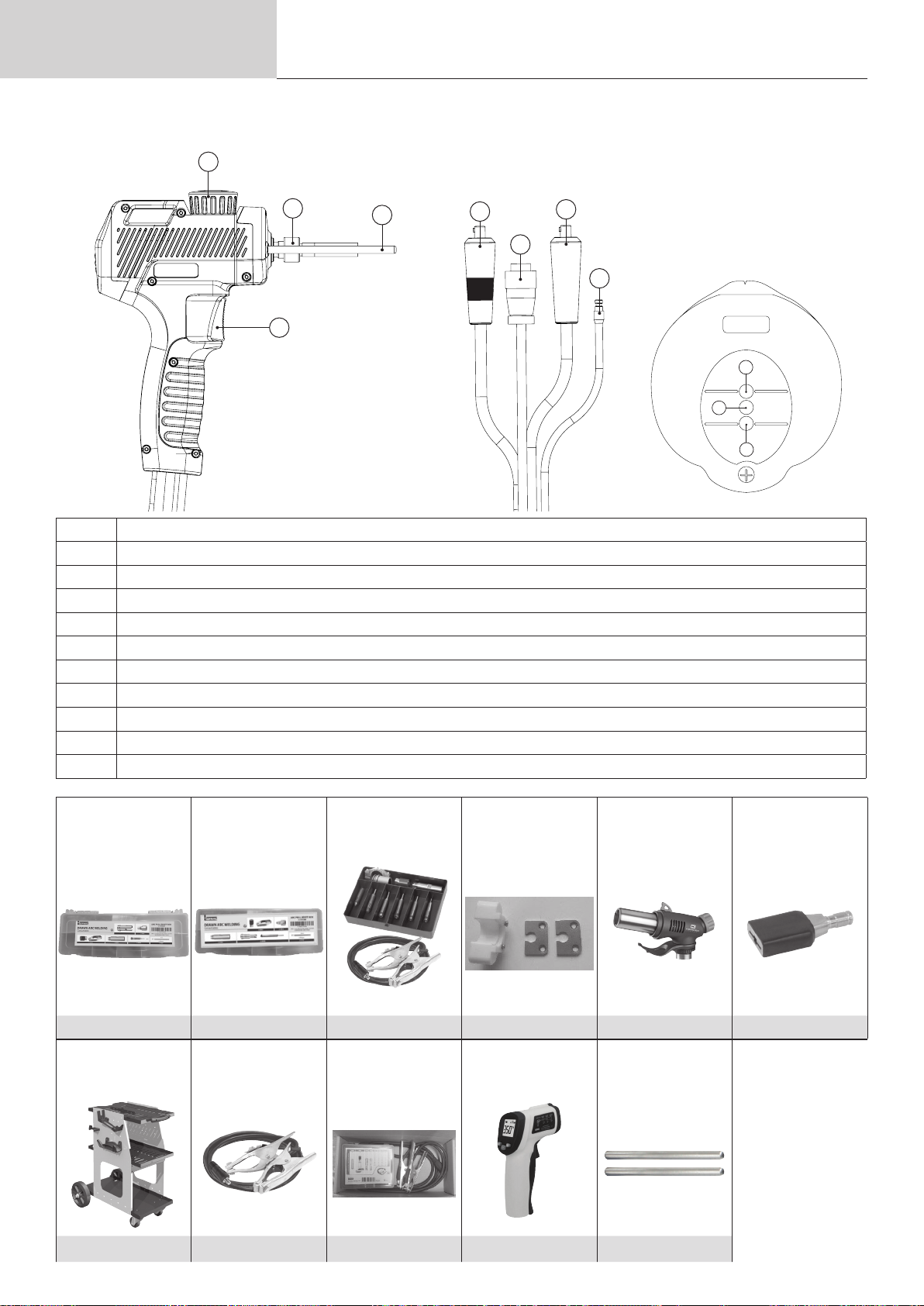
Betriebsanleitung
PROTOTYPE
Übersetzung der
Originalbetriebsanleitung
Abb. 2: Außenansicht der Pistole und ihres HMI (ohne Schweißgabel oder Zubehör)
3
ARCPULL 350
2
1
4
1 Brennertaster
2 Rändelmutter des Elektrodenhalters
3 Stangenverriegelungsrad
4 Massenanschluss-Stifte
5 Steueranschluss Pistolen-Kabelschlauchpaket
6 Texasbuchse positiv
7 Negative Texasbuchse
8 Gasanschluss
9 LED bereit (grün)
10 LED Kontakt (blau)
11 LED Fehler (rot)
6
7
5
8
9
11
10
ArcPull Rivet Box1
350 – 24kN
ArcPull Rivet Box2
350 – 50 kN
Verschleißteile-Box
Arcpull stud holder
box
Adapter
Keramik Ø 6 und Ø 8
Heißluftpistole
(wird ohne Kartusche
geliefert)
Zugringhalter
064584 073388 064591 (068339) 075979 060777 059610
Wagen Weld 810 Massekabel Dop-
pelklemme 350A
Koer Stifthalter
M4 bis M8 - Dicult
Access
Infrarot-Thermometer
Masseanschluss-
037489 070714 070813 079922 059627
68

Betriebsanleitung
3. VERSORGUNG UND INBETRIEBNAHME
• Dieses Gerät wird mit einem 16 A-Stecker vom Typ CEE7/7 geliefert und muss an eine einphasige Elektroinstallation
mit geerdetem Neutralleiter zwischen 208 VAC et 240 VAC (50 - 60 Hz) angeschlossen werden. Der eektiv aufgenommene Strom (l1e) ist auf dem Gerät für maximale Betriebsbedingungen angegeben.
Überprüfen Sie, ob die elektrische Installation und ihre Schutzvorrichtungen (Sicherung und/oder Schutzschalter) mit
dem Strom, der bei der Verwendung benötigt wird, kompatibel sind. Dieses Gerät ist so konzipiert, dass es an einer
elektrischen Anlage mit einem 16 A-Leistungsschalter der Kurve C, D oder K betrieben werden kann.
In Ländern mit abweichenden Netzversorgungswerten kann ein Tausch des Netzsteckers erforderlich sein, um die
maximale Leistung abrufen zu können. Der Anwender muss sicherstellen, dass der Stecker zugänglich ist.
Übersetzung der
Originalbetriebsanleitung
ARCPULL 350
• Das Einschalten erfolgt, indem der M/A-Schalter auf „|“ gestellt wird.
• Das Gerät schaltet sich in den Schutzmodus, wenn die Versorgungsspannung mehr als 265
V AC beträgt (auf dem Bildschirm wird die Meldung NETZFEHLER angezeigt). Der Normalbe-
trieb wird wieder aufgenommen, sobald die Versorgungsspannung wieder in den Nennbereich
zurückkehrt.
3.1. ANSCHLUSS AN EINEN GENERATOR
Dieses Gerät kann mit einphasigen Generatoren betrieben werden, sofern diese die folgenden Anforderungen erfüllen:
- Die Spannung muss Wechselstrom sein, wie angegeben geregelt (208 bis 240 VAC) und mit eine Spitzenspannung
von weniger als 400 V,
- Die Frequenz muss zwischen 50 und 60 Hz liegen.
- Die Leistung muss mindestens 15 kVA betragen.
Diese Bedingungen müssen unbedingt überprüft werden, da viele Generatoren Hochspannungsspitzen erzeugen, die
Geräte beschädigen können.
3.2. VERWENDUNG EINES VERLÄNGERUNGSKABELS
Dieses Gerät kann mit einem Verlängerungskabel an die elektrische Anlage angeschlossen werden, sofern es die
folgenden Anforderungen erfüllt:
- Einphasiges Verlängerungskabel mit Erdungsleiter
- Die Länge darf 10 m nicht überschreiten
- Der Querschnitt der Leiter darf nicht kleiner als 2,5 mm² sein
DE
3.3. ANSCHLUSS DER PISTOLE AN DIE STROMQUELLE
Das Anschließen und Trennen des Steuersteckers der Pistole
an der Generatorbasis muss bei ausgeschaltetem Generator
erfolgen.
Der Ring des Steueranschlusses der Pistole muss vor der
Inbetriebnahme des Geräts immer korrekt auf den Sockel des
Generators geschraubt werden.
An diese Stromquelle kann eine ArcPull 700 Pistole angeschlossen werden. Verwenden Sie in diesem Fall
Texas-Adapter 25mm² -> 50mm² ( 2 x 038127), um die Texasstecker der Pistole mit den Buchse der Stromquelle zu
verbinden.
69

Betriebsanleitung
3.4. AKTUALISIERUNG DES GERÄTS
Das Gerät verfügt über einen USB-Anschluss an der Vorderseite, der durch
eine Kappe geschützt ist, um seine Software zu aktualisieren (Hinzufügen von
Synergien, Funktionen). Wenden Sie sich an Ihren Händler, um weitere Einzel-
heiten zu erfahren.
4. VERFAHREN ZUM SCHWEISSEN EINES AUFSATZSTÜCKS MIT HUBZÜNDUNG
Mit der Hubzündung können Aufsatzstücke (Zugring, Stifte, Masseklötze, Nägel, Betonanker usw.) an ein Trägerteil
geschweißt werden, indem die beiden Teile mithilfe eines Lichtbogens zum Schmelzen gebracht und beide Teile miteinander in Kontakt gebracht werden.
Erinnerung an das Prinzip des Hubzündungsschweißens (weitere Informationen nden Sie in ISO 14555):
Man unterscheidet vier Hauptphasen: Zündung, Reinigung, Lichtbogen und Anschweißen
Phase Zündung Beizung Lichtbogen Befestigung
T (ms) 0 bis 200 ms
I (A) ≈ 80-150 A 50 bis 60 A 50 bis 350 A ≈80-150 A
Übersetzung der
Originalbetriebsanleitung
10 bis 800
ms
ARCPULL 350
0 bis 50 ms
Zündung: Das Aufsatzstück (Zugring, Stifte usw.) wird mit dem Trägerblech in Kontakt gebracht. Ein Druck auf den
Brennertaster startet den Schweißvorgang: Die Stromquelle schickt Strom an den Stift, die Pistolenachse steigt leicht
an, es entsteht ein Lichtbogen mit geringer Stärke.
Abtragung: diese Phase könnte auch als Vorwärmen bezeichnet werden. Die Stromquelle reguliert einen Strom, um
einen Lichtbogen mit geringer Stärke zu gewährleisten, die durch diesen Lichtbogen erzeugte Wärme ermöglicht:
- Verunreinigungen des Trägerblechs (Fette, Öle, elektrolytische Verzinkung) zu verbrennen.
- die beiden Teile vorzuwärmen und so den Wärmeschock des Schweißbogens zu begrenzen, um die Qualität der
Schweißnaht zu verbessern.
In dieser Phase schmelzen weder das Aufsatzstück noch das Trägerblech. Ebenso wird in dieser Phase die
Zinkschicht von verzinktem Blech nicht freigelegt.
Lichtbogen: Die Stromquelle erhöht den Strom erheblich, um einen energiereichen Lichtbogen zu erzeugen, der ein
Schmelzbad auf dem Trägerblech erzeugt und das Ende des Aufsatzstücks zum Schmelzen bringt.
Befestigung: Die Pistole taucht das Aufsatzstück in das Schmelzbad.
5. STIFTMODELL UND SCHUTZ DES SCHMELZBADES
Die Arten von Aufsatzstücken (Form, Abmessungen, Material), die der Hubzündung zugeordnet werden, sind in der
Norm ISO 13918 aufgelistet. Neben Aufsatzstücken aus kohlenstoarmem Stahl, Edelstahl und kupferbeschichtetem
Stahl kann das Gerät auch einige Aufsatzstücke aus Aluminium schweißen.
70

Betriebsanleitung
5.1. OBERFLÄCHENBESCHAFFENHEIT DES TRÄGERTEILS UND ABTRAGUNG
Das Einschweißen muss an einem fettfreien Trägerteil erfolgen. Es ist auch erforderlich, dieses
Trägerteil zu entfernen, wenn es einer chemischen Behandlung unterzogen wurde (Zinkschicht für
verzinkten Stahl, Korrosionsschutz für Stähle, die einer Wärmebehandlung unterzogen wurden,
Aluminiumoxid für Aluminium).
Das Schweißen von Aufsatzstücken, vor allem von Aluminiumteilen, sollte auf einem ebenen Träger-
teil erfolgen.
Übersetzung der
Originalbetriebsanleitung
ARCPULL 350
DE
5.2. STÄRKE DES TRÄGERBLECHS IN ABHÄNGIGKEIT VOM DURCHMESSER DES STIFTS
Mit Ausnahme von spezischen Anwendungen im Zusammenhang mit Autokarosserien (Anbringen von Zugringen)
darf die Dicke des Trägerblechs bei Stahl nicht weniger als ¼ des Durchmessers der Basis des Aufsatzstücks und bei
Aluminium nicht weniger als ½ des Durchmessers betragen.
Beispiele (Liste nicht vollständig)
Zu schweißende Stücke
(gemäß ISO 13918)
Stahlstift Typ DD M8 8 mm 2 mm
Stahlstift Typ PD M6 5,35 mm 1,3 mm
Stift AlMg Kurzzeit Typ PS M8 9 mm 2 mm
Stift AlMg Kurzzeit Typ IS (Innengewinde) M5 9 mm 2 mm
5.3. SCHUTZ DES SCHMELZBADS
Je nach dem zu schweißenden Material kann ein Schutz des Schmelzbades durch eine Keramikhülse oder durch
Schutzgas erforderlich sein.
In der folgenden Tabelle sind die Schutzgase aufgelistet, die je nach den zu schweißenden Stücken und deren Material verwendet werden sollten. Diese Schutzgase maximieren die Haltbarkeit der Schweißnaht und entsprechen dem
Gas, das verwendet werden sollte, wenn das Gerät im Synergie-Modus arbeitet (siehe §8.1).
Basisdurchmesser Mindeststärke des Blechs
Diese Tabelle dient nur zur Orientierung. Vorherige Schweißversuche werden empfohlen.
Material Zu schweißendes Aufsatzstück Keramik
hülse
Aluminium
(Al, AlMg, AlMgSi)
Kohlenstoarmer
Stahl
(Fe)
Kupferbeschichteter Stahl
(FeCu)
Aluminium-Zugring Nicht möglich Argon Nicht empfohlen
Stift, Innengewindestift Nicht möglich ArHe 30 % Nicht möglich
Grobgewindebolzen Nicht möglich ArHe 30 % Nicht möglich
Stahl-Zugring Nicht möglich ArCO² 8 % Möglich
Stift, Innengewindestift OK ArCO² 8 % Nicht empfohlen
Stift, Innengewindestift, Isoliernagel,
Grobgewindebolzen
Nicht möglich ArCO² 8 % Nicht empfohlen
Gas Gasfrei
71

Betriebsanleitung
Übersetzung der
Originalbetriebsanleitung
ARCPULL 350
Edelstahl
Stift, Innengewindestift Nicht empfohlen ArCO² 8 % Nicht empfohlen
Nietenausziehstift aus Edelstahl Nicht empfohlen ArCO² 2 % Nicht empfohlen
Zu verwendendes Zubehör
Stifthalter-Kof-
fer (06
4591)
mit Adapter für
Keramikhül-
sen-Standardhalter (075979)
Koer Stifthalter (06
Koer Stifthalter Dicult Access
(07
0813)
ArcPull Rivet Box 1 350 24 kN
(
064584
)
ArcPull Rivet Box 2.350 50 kN
(07338
8)
4591)
Bei der Verwendung von Schutzgas sollte der Gasuss zwischen 12 l und 15 l/min eingestellt werden.
Hinweis: Bei Aluminiumschweißungen kann reines Argon (Ar), anstelle des 30%igen Argon-Helium-Gemisches (ArHe30
%), verwendet werden.
Überschreiten Sie nicht 5Nm beim Anziehen einer Verbindung zum Gaseinlass des
Geräts.
5.4. AUSWAHL DES SCHWEISSZUBEHÖRS
Die Wahl des zu verwendenden Schweißzubehörs richtet sich nach der Art des zu schweißenden Aufsatzstücks (Typ,
Abmessungen, Material), der Schweißposition und dem geeigneten Schutz (Gas, gasfrei und Keramikhülse). Die
folgende Tabelle gibt eine Hilfestellung bei der Auswahl dieses Zubehörs.
Zubehör Adapter für Kera-
mikhülsen-Standardhalter
(075979)
Zu schweißende
Stücke
(gemäß ISO 13918)
Länge des zu
schweißenden
Stücks
Max. Durchmes-
ser der Basis des
zu schweißenden
Stücks
Stift PD, RD, DD
Zapfen
25 mm bis
65 mm
Flach (PA), wenn > 6mm
Ohne Beschränkung wenn ≤ 6mm
Koer Stifthalter
(064591)
Stift PD, RD, DD
und Kurzzeit PS
Innengewindestift
Kurzzeit PS
Zapfen UD und
Kurzzeit US
Isoliernagel
25 mm bis
30 mm
(100 mm für die
Isoliernägel)
Schweißstelle (gemäß ISO 6947)
Koer Stifthalter
Dicult Access
(070813)
Stift PD, RD, DD
und Kurzzeit PS
Innengewindestift
Kurzzeit PS
Zapfen UD und
Kurzzeit US
Isoliernagel
25 mm bis
70 mm
(100 mm für die
Isoliernägel)
ArcPull Rivet Box1
350 24 kN (064584)
ArcPull Rivet Box2
350 – 50 kN (Art.
Nr. 073388)
Nietenausziehstift Zugring
Ohne Beschränkung
Ringhalter
(059610)
72
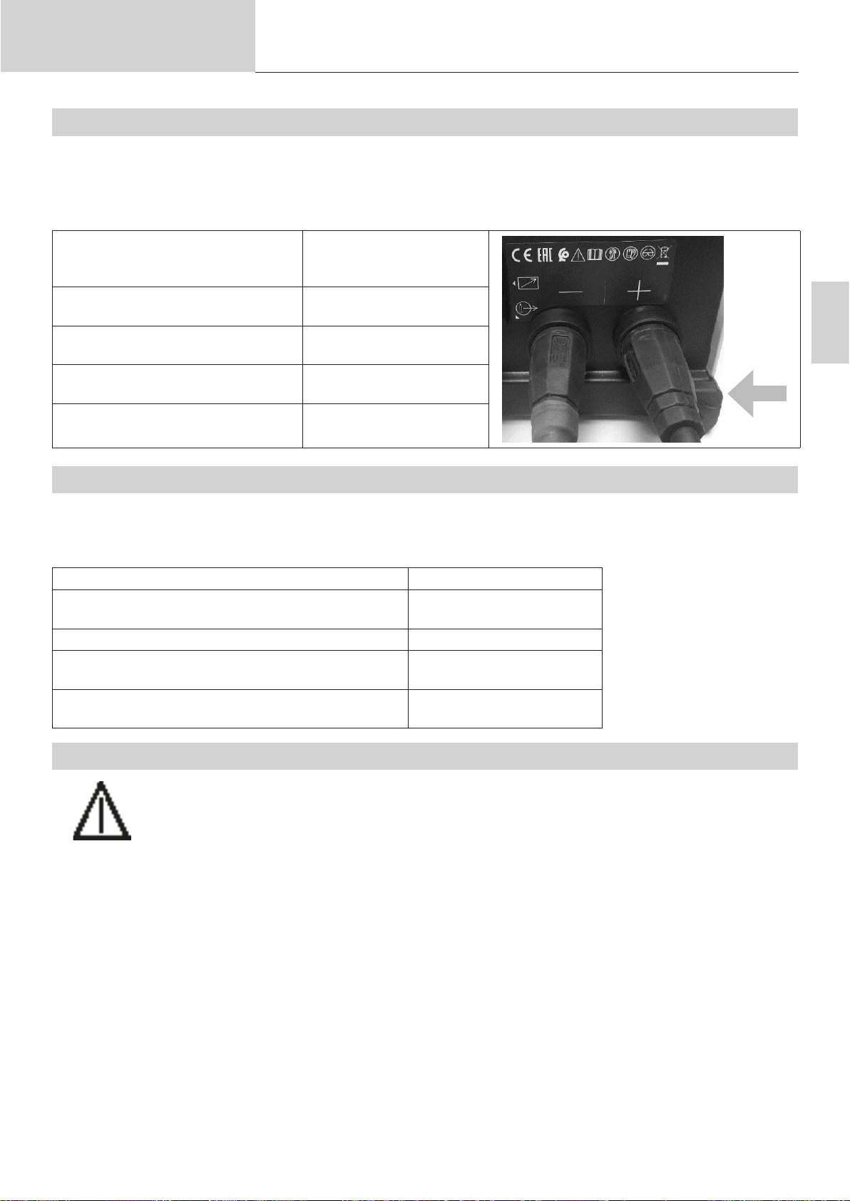
Betriebsanleitung
5.5. POLARITÄT DER PISTOLE
Die Polarität der Pistole wirkt sich auf die Qualität der Schweißstelle aus.
Abhängig von der Art des zu schweißenden Teils und seinem Material ist es vorzuziehen, den Pluspol der Pistole
mit dem Plus- oder Minuspol des Generators zu verbinden. Nachfolgend die Tabelle der von GYS gewählten Pola-
ritätswahl.
Zu schweißendes Aufsatzstück Anschluss der positiven
Aluminium-Zugring Negative Texasbuchse der
Stahl-Zugring Positive Texasbuchse der
Nietenausziehstift Negative Texasbuchse der
Stift, Innengewindestift, Isoliernagel,
aus kupferbeschichtetem Stahl
Übersetzung der
Originalbetriebsanleitung
Texas der Pistole (rote
Markierung)
Stromquelle (-)
Stromquelle (+)
Stromquelle (-)
Positive Texasbuchse der
Stromquelle (+)
ARCPULL 350
-
+
DE
5.6. SCHWEISSPROZESS-GESCHWINDIGKEIT
Die Geschwindigkeit des Schweißgeräts wird dynamisch berechnet, um einen eektiven, dem Netz entnommenen Strom von 16 A nicht zu überschreiten. Abhängig von der Art des zu schweißenden Aufsatzstücks und damit
vom Schweißstrom und der Schweißzeit hat das Gerät eine mehr oder weniger lange Ruhezeit zwischen zwei
Schweißvorgängen.
Zu schweißendes Stück Geschwindigkeit
Zugring AlMg mit 1,5 mm bei einer Dicke von
1 mm
Nietenausziehstift Ø 5 17/min
Kupferbeschichteter Stahlstift mit 2 mm Dicke mit
Schutzgas
Kohlenstoarmer Stahlstift M8 mit 8 mm Dicke mit
Schutzgas
5.7. POSITIONIERUNG DER MASSEKLEMMEN UND DES LICHTBOGENSCHACHTS
Mit Ausnahme der Anbringung von einem Zugring für die Karosserie (siehe §7.1), bei der die Masseaufnahme durch die Massenstifte (Nr. 4 - Abb. 2) gewährleistet wird, ist die Verwendung einer
versetzten Massenklemme erforderlich.
Für das Schweißen von die nicht größer als einen Ø von 5 mm haben, reicht eine einzige Masseklemme aus. Bei höheren Werten muss ein Erdungskabel mit zwei Klemmen verwendet werden, um eine Lichtbogenlöschung zu vermeiden.
19/min
8/min
4/min
Zur Erinnerung: Die Lichtbogen Kegelgröße ist proportional zum Schweißstrom und kann durch Befestigung von
Masseklemmen beeinusst werden. Hinweis auf die Norm ISO 14555 zur Positionierung der Masseklemmen in Abhängigkeit von der Schweißkonguration.
73

Betriebsanleitung
1. Fall: Schweißen auf
Flachblech
2. Fall Schweißen auf Blech
mit Metallhindernis
Übersetzung der
Originalbetriebsanleitung
Ursache Lösung
ARCPULL 350
3. Schweißen auf IPN
6. INSTALLATION VON ZUBEHÖR UND EINSTELLUNG DER PISTOLE
Das Anbringen von Zubehörteilen und deren Einstellung an der Pistole muss
unbedingt wie folgt erfolgen:
- Pistole an der Stromquelle angeschlossen
- Gerät unter Spannung
- Initialisierungsphase der Pistole abgeschlossen (Auorderung zum Ab-
Appui gachette
drücken der Brennertaste)
6.1. AUSTAUSCH UND ANPASSUNG DER LÄNGE DER MASSENANSCHLUSS-STIFTE (059627)
Hinweis 1: Die Masseanschluss-Stifte müssen ausgetauscht werden, wenn sie an ihren Enden zu starke Abnutzung
aufweisen oder wenn sie durch einen Sturz der Pistole verbogen wurden.
Hinweis 2: Bei Verwendung der Koer ArcPull Rivet Box1 und 2 (Art.-Nr. 064584 und 073388) zum Ausziehen der
Nieten sowie der Dicult Access Box (Art.-Nr. 070813) müssen die in der Verpackung des ArcPull350 en-
thaltenen kurzen Stifte verwendet werden.
Lösen Sie das Feststellrad (Nr. 3 in Abbildung 2),
damit die Masseanschluss-Stifte (Nr. 4 in Abbildung
2) so weit wie möglich aus der Pistole herauskom-
men.
Dann ziehen Sie das Feststellrad wieder an.
74

Betriebsanleitung
Lösen Sie die beiden Schrauben an der Vorderseite
und heben Sie die Abdeckung zur Vorderseite der
Pistole hin ab.
Lösen Sie die beiden Klemmschrauben der Stifte
leicht.
Übersetzung der
Originalbetriebsanleitung
ARCPULL 350
Wenn Sie Stifte wechseln, ziehen Sie die Stifte
heraus und setzen Sie dann neue ein.
Passen Sie die Länge der Pistolenstangen an den
Typ des verwendeten Schweißzubehörs an (Maß
zwischen Stangenspitze und Flanschkante).
Zubehör L (mm)
Ringhalter (059610) 120 mm
Koer mit Nietenauszieher ArcPull
Rivet Box1 350 – 24 kN (064584)
Koer mit Nietenauszieher ArcPull
Rivet Box2 350 – 50 kN (073388)
Koer Stifthalter M4 bis M8 (068339) 120 mm
Keramikadapter Ø 6 und Ø 8 (075979) 120 mm
Koer Stifthalter M4 bis M8 Dicult Ac-
cess (070813)
Ziehen Sie die beiden Klemmschrauben der Stifte
an.
55 mm
75 mm
75 mm
DE
L
Bringen Sie die Abdeckung wieder an der Vorderseite der Pistole an und schrauben Sie die beiden
Halteschrauben wieder ein.
6.2. EINSTELLUNG EINES STIFTHALTERS/ISOLIERNAGELHALTERS
Hinweis 1: Die Einstellung des Stifthalters für den Nietenausziehstift ist spezisch. Sie wird in den Paragraphen (siehe
§6.4 und §6.5) näher erläutert.
Hinweis 2: Bei Anbringung eines Isoliernagels ist keine Einstellung erforderlich. Führen Sie den Isoliernagel bis zum
Anschlag in den Nagelhalter ein.
75

Betriebsanleitung
Übersetzung der
Originalbetriebsanleitung
ARCPULL 350
6.2.1. EINSTELLUNG EINES STIFTHALTERS FÜR DIE SCHWEISSUNG OHNE KERAMIKHÜLSE
Die unten beschriebene Einstellung des Stifthalters gilt für alle Aufsatzstücke mit Ausnahme derjenigen, die unter dem
Schutz einer Keramikhülse (075979) geschweißt werden, sowie für Nietenausziehstifte (siehe §6.4 und §6.5).
Einstellschraube
Konter
mutter
5 mm
1) Lösen Sie die Kontermutter der Einstellschraube des Stifthalters.
2) Setzen Sie das Aufsatzstück in den Stifthalter ein und stellen Sie die Schraube so ein, dass das Ende des Aufsa-
tzstücks 5 mm über den Stifthalter hinausragt.
3) Ziehen Sie die Kontermutter fest.
Hinweis: Wenn die Schweißung des Aufsatzstücks die Mar-
kierungen des Stifthalters an der Schweißung aufweist,
stellen Sie die Schraube des Stifthalters so ein, dass
der Stift etwas weiter aus dem Aufsatzstück herausragt.
Markierungen
6.2.2. EINSTELLUNG EINES STIFTHALTERS FÜR DIE SCHWEISSUNG MIT KERAMIKHÜLSE
Einstellschraube
Konter
mutter
15 mm
1) Lösen Sie die Kontermutter der Einstellschraube des Stifthalters.
2) Setzen Sie das Aufsatzstück in den Stifthalter ein und stellen Sie die Schraube so ein, dass das Ende des Aufsa-
tzstücks mindestens 15 mm über den Stifthalter hinausragt.
3) Ziehen Sie die Kontermutter fest.
6.3. VERWENDUNG DES ZUBEHÖRS ZUR INSTALLATION DES ZUGRINGS (059610)
Lösen Sie die Rändelmutter (Nr. 2 - Abb. 2) der Pistolenantriebswelle leicht.
Positionieren Sie den Ringhalter bis zum Anschlag
und ziehen Sie die Rändelmutter an.
76

Betriebsanleitung
Übersetzung der
Originalbetriebsanleitung
Positionieren Sie den Zugring bis zum Anschlag in
den Ringhalter.
6.4. VERWENDUNG DES KOFFERS ARCPULL RIVET BOX1 350 – 24 KN (064584)
Hinweis: Bereiten Sie die Masseanschluss-Stifte vor, wie in §6.1 erklärt.
Entfernen Sie die Stellschraube des Stif-
thalters vollständig und setzen Sie einen
Nietenausziehstift bis zum Anschlag ein.
Entfernen Sie die Rändelmutter (Nr. 2 -
Abb. 2) von der Antriebswelle der Pistole
und schrauben Sie den Stifthalter dort fest.
ARCPULL 350
DE
Schrauben Sie die Schutzgasdüse leicht
auf den Stifthalter, führen Sie den Stifthal-
ter bis zum Anschlag ein und ziehen Sie
die Schutzgasdüse fest.
Bauen Sie den Schaft zum Einsetzen der
Stange mit dem Gleitschuh zusammen
(achten Sie auf die Positionierung der
Löcher) und montieren Sie das Ganze auf
den Stangen der Pistole.
Lösen Sie das Pistolenrädchen (Nr. 3 -
Abb. 2).
Stellen Sie den Schaft so ein, dass die
Spitze des Nietenausziehstifts leicht herausragt (0,5-2 mm), und ziehen Sie das
Rädchen der Pistole fest.
0,5 bis 2 mm
6.5. VERWENDUNG DES KOFFERS ARCPULL RIVET BOX2 350 – 50 KN (073388)
Hinweis: Bereiten Sie die Masseanschluss-Stifte vor, wie in §6.1 erklärt.
Führen Sie den Edelstahl-Nietenaus-
ziehstift in den Stifthalter ein und stellen
Sie die Schraube des Stifthalters so ein,
dass gewährleistet ist, dass er 13,5 bis 15
mm aus dem Stifthalter herausragt.
13,5 bis 15 mm
77

Betriebsanleitung
Übersetzung der
Originalbetriebsanleitung
Entfernen Sie die Rändelmutter (Nr. 2 -
Abb. 2) von der Antriebswelle der Pistole
und schrauben Sie den Stifthalter dort fest.
Schrauben Sie die Schutzgasdüse leicht
auf den Stifthalter, führen Sie den Stifthal-
ter bis zum Anschlag ein und ziehen Sie
die Schutzgasdüse fest.
Bauen Sie den Schaft zum Einsetzen der
Stange mit dem Gleitschuh zusammen
(achten Sie auf die Positionierung der
Löcher) und montieren Sie das Ganze auf
den Stangen der Pistole.
ARCPULL 350
Lösen Sie das Pistolenrädchen (Nr. 3 -
Abb. 2).
Stellen Sie den Schaft so ein, dass die
Spitze des Nietenausziehstifts leicht herausragt (0,5-2 mm), und ziehen Sie das
Rädchen der Pistole fest.
0,5 bis 2 mm
6.6. VERWENDUNG DES KOFFERS STUD HOLD BOX 350 (068339)
Hinweis 1: Bereiten Sie die Masseanschluss-Stifte vor, wie in §6.1 erklärt.
Hinweis 2: Bereiten Sie den Masseanschluss-Stift vor, wie in §6.2 erklärt.
Entfernen Sie die Rändelmutter (Nr.
2 - Abb. 2) von der Antriebswelle
der Pistole und schrauben Sie den
Stifthalter dort fest.
Schrauben Sie die Schutzgasdüse
leicht auf den Stifthalter, führen Sie
den Stifthalter bis zum Anschlag ein
und ziehen Sie die Schutzgasdüse
fest.
78

Betriebsanleitung
Übersetzung der
Originalbetriebsanleitung
Bauen Sie die Schutzgaskappe
und den Gleitschuh entsprechend
der Konguration des gewählten
Werkzeugs zusammen: (Achten Sie
auf die Position der Löcher).
Montieren Sie die Baugruppe auf den
Pistolenstangen.
ARCPULL 350
Konguration 1 Konguration 2
DE
Lösen Sie das Pistolenrädchen (Nr.
3 - Abb. 2).
Stellen Sie die Baugruppe aus
Gleitschuh + Kappe so ein, dass das
Ende des zu schweißenden Teils
leicht herausragt (0,5-2 mm), und
ziehen Sie das Rädchen der Pistole
fest.
0,5 bis 2 mm
0,5 bis 2 mm
6.7. VERWENDUNG DES ADAPTERS FÜR KERAMIKHÜLSE (075979)
Hinweis: Sie benötigen den Koer Stud Holder 350 (Art. Nr. 068339), um den Adapter für die Keramikhülse verwen-
den zu können.
6.7.1. AUSWAHL DES KERAMIKHÜLSENHALTERS
Wählen Sie die richtige Keramikhülse für das zu schweißende Aufsatzstück (Typ, Durchmesser). Hinweis auf die
Norm ISO 13918 zur Auswahl von Hülsen je nach Art der zu schweißenden Stücke
Typ der Aufsatzstücke Bezeichnung der Hülse nach ISO
Bezeichnung Bezeichnung gemäß ISO 13918
Ganzgewindestift
Zapfen
DD
UD
13918
UF
Teilgewindestift PD PF
Stift mit kurzem Schaft RD RF
79
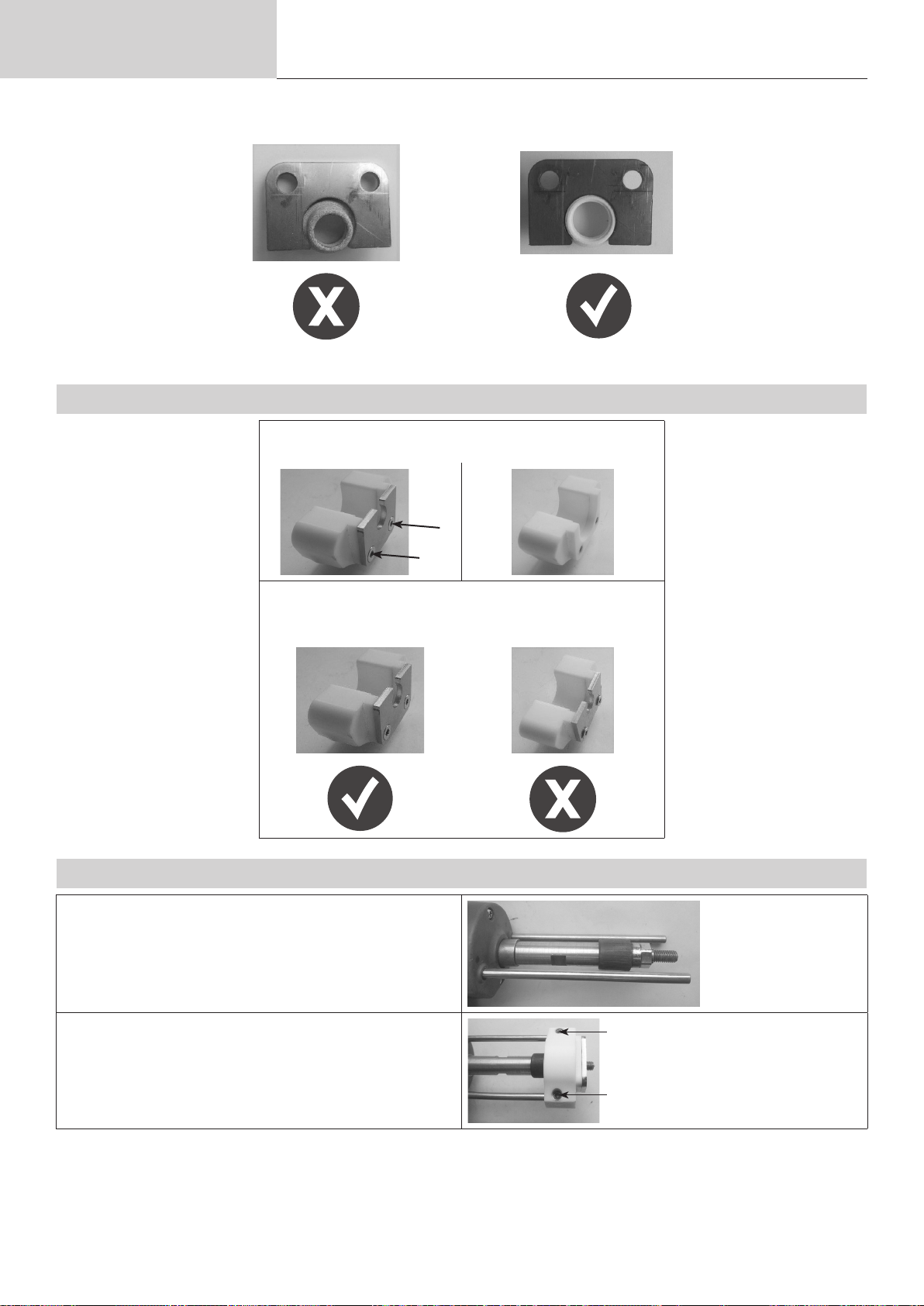
Betriebsanleitung
Die Halterung für die Keramikhülse sollte entsprechend ihrem Durchmesser gewählt werden.
6.7.2. VERFAHREN ZUM WECHSELN DES KERAMIKADAPTERS
Übersetzung der
Originalbetriebsanleitung
Halter zu groß
Lösen Sie die beiden Schrauben und entfernen Sie den
Keramikhalter des Adapters
Angepasster Halter
ARCPULL 350
Setzen Sie den richtigen Halter Adapter wieder ein
(wobei die Fräsungen nach außen zeigen), und
schrauben Sie die beiden Schrauben wieder ein.
6.7.3. ANBRINGEN DES ZUBEHÖRS AUF DER PISTOLE
Wiederholen Sie die ersten beiden Schritte des Verfahrens zum Einsetzen des Stifthalters in die Antriebswelle der Pistole
Montieren Sie den Adapter am Ende der Stangen und
ziehen Sie die beiden Verriegelungsschrauben der Stangen an
80

Betriebsanleitung
Übersetzung der
Originalbetriebsanleitung
ARCPULL 350
Die Keramikhülse auf den Adapter aufsetzen.
Lösen Sie das Pistolenrädchen (Nr. 3 - Abb. 2).
Stellen Sie die Baugruppe so ein, dass das Ende des zu
schweißenden Teils leicht herausragt (0,5-2 mm).
Ziehen Sie das Pistolenrädchen fest.
0,5 bis 2 mm
6.8. VERWENDUNG DER KOFFER ARCPULL 350 DIFFICULT ACCESS (070813)
Hinweis 1: Bereiten Sie die Masseanschluss-Stifte vor, wie in §6.1 erklärt.
Hinweis 2: Bereiten Sie den Masseanschluss-Stift vor, wie in §6.2 erklärt.
Hinweis 3: Wählen Sie den passenden Schaft für das Material des zu schweißenden Aufsatzstücks. Der mit einem
versehene Schaft ist nicht zum Schweißen von Aluminiumteilen geeignet.
DE
Entfernen Sie die Rändelmutter (Nr. 2 - Abb.
2) von der Antriebswelle der Pistole und
schrauben Sie den Stifthalter dort fest.
Schrauben Sie die Schutzgasdüse leicht
auf den Stifthalter, führen Sie den Stifthalter
bis zum Anschlag ein und ziehen Sie die
Schutzgasdüse fest.
Bauen Sie den Schaft zum Einsetzen der
Stange mit dem Gleitschuh zusammen
(achten Sie auf die Positionierung der Löcher) und montieren Sie das Ganze auf den
Stangen der Pistole.
Lösen Sie das Pistolenrädchen (Nr. 3 - Abb.
2).
Stellen Sie den Schaft so ein, dass die
Spitze des Nietenausziehstifts leicht herausragt (0,5-2 mm), und ziehen Sie das
Rädchen der Pistole fest.
0,5 bis 2 mm
81

Betriebsanleitung
7. MANIPULATION DER PISTOLE
7.1. SCHWEISSEN VON ZUGRINGEN
1. Montieren Sie den Ringhalter (siehe §6.3).
2. Entfernen Sie den Lack an der Stelle, an der geschweißt werden soll.
3. Wählen Sie die für den zu schweißenden Ring geeignete Synergie aus.
4. Verbinden Sie die negative Texasbuchse der Pistole mit dem Gerät (keine
Verwendung einer Massenklemme).
5. Bei manuellem Betrieb: die digitale Feder „Flex“ auf OFF stellen (siehe §
8.4.2).
6. Stecken Sie einen Ring in den Ringhalter.
7. Entriegeln Sie die Masseanschluss-Stifte mit dem Rädchen.
8. Positionieren Sie die Pistole auf dem Blech und bringen Sie den Ring
mit dem Blech in Kontakt. Sobald die Pistole einen „Piepton“ von sich gibt
oder ihre Kontakt-LED (blau) leuchtet, verriegeln Sie die Stützstifte mit dem
Rädchen.
9.
Drücken Sie den Brennertaster und halten
Sie dabei die Pistole fest auf das Trägerblech
gedrückt.
Übersetzung der
Originalbetriebsanleitung
ARCPULL 350
10. Entriegeln Sie nach dem Schweißen das Rädchen, um die Stifte zu lösen,
und heben Sie die Pistole an, um den Ring freizulegen.
Alle 30 Schweißnähte der Zugringe erscheint die Meldung «Stangen
überprüfen» auf dem Bildschirm. Überprüfen Sie die Enden der Erdungsstäbe
(Nr. 4, Abbildung 2). Wenn sie Lötspuren aufweisen, schmirgeln Sie sie leicht
mit einem Schleifpapier ab, um den elektrischen Kontakt wiederherzustellen.
Drücken Sie , um zu bestätigen und den Zähler zurückzusetzen.
Hinweis: Diese Funktion ist nicht aktiviert, wenn eine Pistole von ArcPull 700
verwendet wird (siehe §2.3).
7.2. SCHWEISSEN VON AUFSATZSTÜCKEN AUSSERHALB DER ZUGRINGE
1. Zubehör montieren und einstellen (Schutzgas, Keramikadapter, Zubehör zum
Ausziehen von Nieten)
2. Positionieren Sie die Masseklemmen auf dem Trägerblech, wobei der Abstand
zwischen den Klemmen und dem Schweißbereich des Rings gleich groß sein
sollte (siehe § 5.7). Die Bereiche für den Massestecker sollten sandgestrahlt,
gereinigt und fettfrei sein.
3. Wählen Sie die entsprechende Synergie, oder bei manuellem Betrieb: die digi-
tale Feder „Flex“ auf ON stellen (siehe § 8.4,2).
4. Platzieren Sie die Pistole auf dem Blech. Sobald die Pistole einen „Piepton“
von sich gibt oder ihre Kontakt-LED (blau) leuchtet, drücken Sie die Pistole, damit
das Zubehör richtig auf das Blech gedrückt wird (es darf keine Kippbewegung
geben).
5.
Drücken Sie den Brennertaster und halten
Sie dabei die Pistole fest auf das Trägerblech
gedrückt.
6. Wenn die Schweißung abgeschlossen ist, heben Sie die Pistole an, um das
Aufsatzstück freizugeben.
82

Betriebsanleitung
8. FUNKTIONSWEISE DES GERÄTS
Abb. 3: Ansicht der Tastatur der Stromquelle
Übersetzung der
Originalbetriebsanleitung
ARCPULL 350
1
2
3
1 Bildschirm
2 Taste G+
3 Taste G4 Taste D+
5 Taste D-
6 Taste Hauptmenü/Bestätigen
7 Taste Zurück/Löschen
4
DE
5
6
7
verfügt über einen synergetischen und einen manuellen Betriebsmodus sowie eine Möglichkeit, Schweißkongurationen zu speichern und abzurufen.
Beim Einschalten nimmt das ArcPull350 den Betriebsmodus wieder auf, in dem es sich bei seinem letzten Stopp
befand.
Die Änderung des Modus (Manuell oder Synergie) und die Erinnerung an die Schweißkonguration erfolgen über das
Hauptmenü.
8.1. SCHWEISSEN IM SYNERGIE-MODUS
Im Modus Synergie werden die Lichtbogenlänge, die Zeiten und Ströme der verschiedenen Schweißphasen automatisch vom Gerät bestimmt. Eine Synergie wird also durch einen bestimmten Typ des zu schweißenden Stücks, sein
Material, seinen Schutzgas, seine Größe und das Trägerblech deniert.
Das zu verwendende Schutzgas wird auf dem Bildschirm angezeigt. Wenn die Polarität der Pistole falsch ist, erscheint
eine Meldung auf dem Bildschirm und die Fehler-LED (rot) der Pistole blinkt.
Die verschiedenen Schweißparameter werden für die von GYS verkauften Aufsatzstücke festgelegt.
Diese Synergien bleiben für längere Aufsatzstücke (siehe §5.4) gültig, solange sie vom gleichen Typ und
aus dem gleichen Material sind wie die von GYS verkauften Aufsatzstücke (nach ISO 13918).
Die Synergien der Aluminium-Aufsatzstücke (ohne Zugringe), wurden auf vorgewärmten Trägerblechen bei einer Tem-
peratur von 50-60 °C ermittelt.
Es empehlt sich, vorher einige Schweißversuche auf einer Testplatte vorzunehmen, um sicherzugehen, dass die
Schweißstelle gut hält.
83

Betriebsanleitung
message
message
Übersetzung der
Originalbetriebsanleitung
ARCPULL 350
Auf dem Hauptbildschirm des Synergie-Modus wird Folgendes angezeigt:
1 - Das Material des Aufsatzstücks: AlMg, Fe, usw.
2 - Die Art des Badschutzes: Gasfrei, Hülse oder die Art des empfohlenen Gases
3 - Das Piktogramm des zu schweißenden Stücks
4 - Die Stärke des Blechs, auf das das Stück geschweißt wird
5 - „Prog“ gefolgt von der Nummer wird bei einer gespeicherten Schweißkonguration angezeigt (siehe § 8.4.3).
6 - Ein Nachrichtenfeld, das den Status angibt, in dem sich das Gerät bendet (siehe § 8.3).
1
5
FeCu Prog 3
2
3
8.1.1. ART DER ZU SCHWEISSENDEN STÜCKE
Ausgehend von der auf dem Bildschirm angezeigten Synergie, die durch einen Stück-Typ(3), sein Material (1) und
seinen Schutz (2) deniert ist, können Sie durch Drücken von G+ und G- nur die Größe des Stücks (M4, M5 usw.)
ändern, ohne das Menü Einstellungen aufrufen zu müssen (siehe § 8.4.1).
Aufsatzstück Name of the electrode
Zugring Ring
Nietenausziehstift
Innengewindestift
Stift (und
Zapfen)
Isoliernagel Nagel
ArCo_8%
M8 4.0
zone de
zone de
6
in the synergic setting
menu
Dorn Bei Auswahl einer Nietausziehstange,
Insert Synergien in Verbindung mit Innengewin-
Bolzen Zugehörige Synergien:
Piktogramme Anmerkungen
4
Durch Drücken von G+ und G- werden
alle im Gerät enthaltenen Ringsynergien
durchlaufen. Das Material (1) und der
Gasschutz (2) werden dynamisch aktualisiert.
ändert sich die Anzeige der Dicke (4) automatisch und entspricht dem Durchmesser
in Millimetern des zu ziehenden Nietkopfs.
destift Kurzzeit Typ US.
Der Mx-Wert entspricht dem Innengewinde
des Stifts.
• Kohlenstoarmer Stahl (Fe) und Edelstahl: Gewindestift Typ DD
• Kupferbeschichteter Stahl (FeCu):
Gewindestift Kurzzeit Typ PS
Zapfen Kurzzeit Typ US
Visuell
Verkleidungsclip
84
Stift
Der Tx-Wert entspricht dem Gewindedurchmesser des Clips.

Betriebsanleitung
message
8.1.2. DICKE DES TRÄGERBLECHS
Angezeigte Stärke in Millimetern.
Um die Stärke des Blechs, auf das das Aufsatzstück geschweißt wird, zu erhöhen oder zu verringern, drücken Sie die
Tasten D+ und D-.
Die Stärkebereiche, die ausgewählt werden können, hängen von der Art, der Größe und dem Material des zu schweißenden Stücks ab.
Wenn die Stärke des Blechs geringer ist als auf dem Bildschirm angezeigt, kann sich das Trägerblech an der
Schweißnaht verformen.
Wenn das Gerät anzeigt, , ist die Blechstärke hoch genug, um die Schweißparameter der Synergie nicht mehr zu
beeinussen.
Wenn dieses Piktogramm nicht erscheint, wurde die maximale Blechstärke erreicht. Bei Überschreitung dieser Stärke
ist die Schweißung des Aufsatzstücks nicht mehr gewährleistet.
Hinweis 1: Wenn eine Synergie für Nietenausziehstifte gewählt wird, ändert sich die Dicke (Piktogramm ) und ents-
pricht dem Durchmesser des Nietkopfes in Millimetern.
Übersetzung der
Originalbetriebsanleitung
ARCPULL 350
DE
Hinweis 2: Wenn Sie vom Synergie-Modus in den Modus Manuell wechseln, werden alle Schweißparameter (Ströme,
Zeiten, Höhen usw.), die mit dem Synergie-Modus verknüpft sind, in den Modus Manuell übertragen. So
können die Einstellungen des Geräts verfeinert werden, wenn die ausgewählte Synergie nicht dem erwarteten Ergebnis entspricht (zu viel oder zu wenig Schweißenergie).
8.2. SCHWEISSEN IM MODUS MANUELL
Im Modus Manuell werden die Zeiten, Ströme, die Hubhöhe des Aufsatzstücks und die Aktivierung der Digitalfeder
vom Benutzer eingegeben.
Auf dem Hauptbildschirm des Modus Manuell wird Folgendes angezeigt:
1 - Die Zeit des Lichtbogens in Millisekunden ( siehe § 4)
2 - Der Strom des Lichtbogens ( siehe § 4)
3 - „Prog“ gefolgt von der Nummer wird bei einer gespeicherten Schweißkonguration angezeigt (siehe § 8.4,3).
4 - Ein Nachrichtenfeld, das den Status angibt, in dem sich das Gerät bendet (siehe § 8.3).
3
Prog 4
t ms I A
1
100 350
2
zone de
4
Um die Lichtbogendauer (Wert ) zu erhöhen oder zu verringern, drücken Sie die Tasten G+ und G-.
Um den Strom des Lichtbogens (Wert ) zu erhöhen oder zu verringern, drücken Sie die Tasten D+ und D-.
Um die anderen Parameter des manuellen Schweißens zu ändern (Strom und Zeit der Schweißphasen), lesen Sie
bitte das Kapitel „Manuelle Einstellungen“.
85

Betriebsanleitung
Menu Principal
8.3. LISTE DER MELDUNGEN, DIE AM UNTEREN RAND DES SCHWEISSBILDSCHIRMS ANGEZEIGT
WERDEN
Meldung Beschreibung
Pistole getrennt Es ist keine Pistole an das Gerät angeschlossen.
Texasbuchse getrennt Die positive Texasbuchse der Pistole ist nicht mit der Stromquelle verbunden (Nr. 6 - Abb.
2).
Texasbuchse
umgekehrt
Bereit Nach dem Ruhezyklus steht das Gerät zum Schweißen bereit.
Einzige Bewegung Ein Druck auf den Brennertaster wurde erkannt, ohne dass ein Aufsatzstück mit dem Trä-
Kontakt Das Gerät erkennt, dass ein Aufsatzstück Kontakt mit dem Trägerblech hat. Wenn das
Schweißung Laufender Schweißzyklus.
Schweißung
abgeschlossen
Gasvorströmung Wird angezeigt, wenn ein Druck auf den Brennertaster erkannt wird, bevor die
Kontakt unterbrochen Wird angezeigt, wenn der Kontakt zwischen dem Aufsatzstück und dem Trägerblech verlo-
Lichtbogenabbruch
(Nur im Synergie-Modus). Die Polarität der Texasbuchse ist umgekehrt zu der von der
Synergie geforderten.
gerblech in Kontakt gekommen ist. Die Pistole führt dann nur eine mechanische Bewegung
aus, die Stromquelle ist nicht aktiv.
Schweißen unter Schutzgas erfolgt, önet sich das Gasmagnetventil für die Gasvorströmu-
ng.
Der Schweißzyklus ist abgeschlossen.
Gasvorströmung abgelaufen ist (siehe § 8.4,4). Damit die Schweißnaht entsteht, müssen
Sie in Position bleiben (Aufsatzstück immer in Kontakt mit dem Trägerblech) und das Ende
der Gasvorströmung abwarten.
ren gegangen ist, bevor die Gasvorströmungszeit abgelaufen ist.
Übersetzung der
Originalbetriebsanleitung
Während des Schweißzyklus kam es zu einem Lichtbogenabbruch.
Eine Überprüfung der Schweißnaht ist erforderlich.
ARCPULL 350
Pistole anheben Wird am Ende des Schweißzyklus angezeigt, wenn sich die Pistole noch auf dem Aufsa-
tzstück bendet
8.4. HAUPTMENÜ
Um das Hauptmenü aus dem Synergie-Modus und dem Modus Manuell aufzurufen, drücken Sie die Taste .
> Réglages
Mode Synergique
Programmes
Configuration
Drücken Sie die Tasten G+ und G-, um den Cursor > der Überschrift zu bewegen. Wählen Sie die Überschrift durch
Drücken der Taste .
• „Einstellungen“ greift auf die Schweißparameter (synergetisch oder manuell) zu.
• „Modus Manuell“ / „Synergie-Modus“ ändert den Schweißmodus des Geräts.
• „Programme“ greift auf Funktionen zum Speichern oder Abrufen von benutzergespeicherten Schweißkongura-
tionen zu.
• „Konguration“ greift auf die erweiterte Konguration des Geräts zu (Sprachen, Gasmanagement, Informationen,
usw.).
Drücken Sie die Taste Zurück, um zum Schweißbildschirm zurückzukehren.
86

Betriebsanleitung
8.4.1. EINSTELLMENÜ IM SYNERGIE-MODUS
Wenn das Gerät im Synergie-Modus arbeitet, können Sie im Menü Einstellungen den Typ des zu schweißenden Aufsatzstücks, seine Größe, sein Material und die Art des Schutzgases auswählen.
Im Synergie-Modus werden die Einstellungen in der Reihenfolge von oben nach unten gewählt:
1 - Einsatztyp „Elektrode“: Stift, Nagel, Ring usw.
2 - Größe des Aufsatzstücks „EP, elekt.“: Mx, Øx, usw.
3 - Material des Aufsatzstücks: Fe, FeCu, Al, usw.
4 - Schutzart der Schweißnaht: Hülse, ohne Gas, oder mit Gas
Hinweis: Wenn das Schweißen unter Schutzgas erfolgen muss, wird das Gas angezeigt, das empfohlen wird, um die
Festigkeit der Schweißnaht zu gewährleisten (siehe § 5.3). Falls dieses Gas nicht verfügbar ist, muss möglicherweise in den Modus Manuell gewechselt werden (siehe § 8.2).
Übersetzung der
Originalbetriebsanleitung
ARCPULL 350
Réglages Synergie
> Electrode > Goujon
Einstellreihenfolge
EP. élec. M8
Matériau FeCu
Gaz ArCo8%
DE
Drücken Sie die Tasten G+ und G-, um den linken Cursor zu bewegen, und drücken Sie die Tasten D+ und D-, um die
Werte der einzelnen Posten zu ändern.
Ein Druck auf die Taste bestätigt die Synergie-Einstellungen und bringt das Gerät zurück zum Synergie-Schweiß-
bildschirm.
Drücken Sie auf die Taste , um die Einstellungen nicht zu übernehmen und zum Hauptmenü zurückzukehren.
8.4.2. EINSTELLMENÜ IM MODUS MANUELL
Wenn das Gerät im Modus Manuell arbeitet können Sie im Einstellungsmenü alle Parameter, die für eine Schweißnaht
wichtig sind, einzeln einstellen.
Réglages Manuel
1
2
6
5
Ressort > ON
3 4
Ein Druck auf die Taste G+ und G- hebt den ausgewählten Parameter hervor. Ein Druck auf die Tasten D+ und D- ändert den Wert dieses Parameters.
1 - Digitalfeder „Flex“:
• Gibt die Antriebsachse des Elektrodenhalters frei (ON) oder blockiert sie (OFF), wenn das Aufsatzstück das Trä-
gerblech berührt.
• Sie sollten diese Funktion für alle Aufsatzstücke außer für die Zugringe aktivieren.
87

Betriebsanleitung
Programmes
2 - Zündung:
• Einstellbar von -2 bis +8. Verwendet direkt den Sollwert des Stromwandlers des Geräts.
• Bei 0 (Standardeinstellung) gewährleistet das Gerät eine optimale Zündung ohne die Gefahr eines Lichtbogenbruchs
beim Anheben des Aufsatzstücks und begrenzt gleichzeitig den Kurzschlussstrom.
• Bei wiederholtem Lichtbogenabriss Zündung leicht erhöhen.
3 - Abbeizen: Zeiteinstellung (in Millisekunden) und Beizstrom. Siehe § 4 für Erläuterungen.
4 - Lichtbogen: Zeiteinstellung (in Millisekunden) und Lichtbogenstrom. Siehe § 4 für Erläuterungen.
5 - Befestigung:
• Einstellbar von -2 bis +8. Verwendet direkt den Sollwert des Stromwandlers des Geräts.
• Bei 0 (Standardwert) sorgt das Gerät für eine optimale Befestigung der Elektrode auf dem Trägerblech
6 - Höhe:
• Höhe (in Millimetern), um die das Aufsatzstück beim Schweißen angehoben wird.
• Eine zu große Höhe verstärkt den Lichtbogenschacht (siehe § 5.7). Eine zu geringe Höhe setzt die Schweißnaht der
Gefahr eines Kurzschlusses aus, da sich das Ende des Stifts beim Schweißen verformt.
7- Stärke :
• Einstellbar von 0 bis 4. Wirkt sich direkt auf die Eintauchkraft des Einsatzes in das Schmelzbad (Schmieden) aus.
• Bei 0 ist die Eintauchkraft gleich null, bei 4 ist sie maximal. Bei Schweißungen, bei denen das Verhältnis zwischen
Durchmesser und maximaler Blechdicke nicht eingehalten wird (siehe §4.2). Es kann erforderlich sein, diese Kraft zu
verringern, um ein Durchstoßen zu vermeiden.
Übersetzung der
Originalbetriebsanleitung
ARCPULL 350
Ein Druck auf die Taste bestätigt die Schweißeinstellungen und bringt das Gerät zurück zum Bildschirm zum
manuellen Schweißen.
Drücken Sie auf die Taste , um die Einstellungen nicht zu übernehmen und zum Hauptmenü zurückzukehren.
8.4.3. MENÜ PROGRAMME
Es können bis zu 99 verschiedene Schweißkongurationen gespeichert werden, unabhängig davon, ob sie synergetisch
oder manuell sind.
> Sauvegarder
Rappeler
Effacer
Effacer tout
Drücken Sie die Tasten G+ und G-, um den linken Cursor zu bewegen und eine der vier Funktionen im Menü Programme auszuwählen (Speichern, Aufrufen, Löschen, Alle löschen).
Ein Druck auf die Taste Zurück önet die angezeigte Funktion.
Drücken Sie auf die Taste Zurück, um zum Hauptmenü zurückzukehren.
Wenn eine Schweißkonguration gespeichert oder aufgerufen wird, wird „Prog“ gefolgt von der Programmnummer auf
dem Schweißbildschirm angezeigt (synergetisch oder manuell).
88

Betriebsanleitung
Configuration
Info
Reset machine
pour valider
8.4.4. MENÜ KONFIGURATION
Übersetzung der
Originalbetriebsanleitung
ARCPULL 350
> Pregaz > 400ms
Postgaz 400ms
Langue FR
Compteurs
Reset machine
Drücken Sie die Tasten G+ und G-, um den linken Cursor zu bewegen (Gasvorströmung, Gasnachströmung, Sprache,
Gerät zurücksetzen, Info.).
Wenn die Punkte Gasvorströmung, Gasnachströmung oder Sprache markiert sind, drücken Sie die Tasten D+ und D-,
um den Wert zu ändern.
Test Einstellbereich Kommentar
Gasvorströmung Dann 0,2 bis 0,3 Sekunden
kein Gas
Gasnachströmung Dann 0,2 bis 0,3 Sekunden
kein Gas
Sprache FR, GB, DE, NL, SP, IT, RU
Für das Schutzgasschweißen wird eine Gasvorströmung von
mindestens 0,4 s empfohlen.
Wenn unter Schutzgas geschweißt wird, ist eine Gasnachströmung von mindestens 0,4 s empfehlenswert.
DE
Drücken Sie auf die Taste Zurück, um zum Hauptmenü zurückzukehren.
8.4.4.1. Zahler
Wenn «Zähler» ausgewählt ist, wird auf dem Bildschirm angezeigt :
- der Tageszähler: Anzahl der korrekt ausgeführten Schweißnähte seit dem Einschalten des Produkts. Dieser Zähler
wird beim Neustart des Produkts auf Null zurückgesetzt.
- den Gesamtzähler: Anzahl der Schweißungen, die das Produkt seit dem Verlassen des Werks korrekt ausgeführt hat.
8.4.4.2. Gerät zurücksetzen
Wenn „Gerät zurücksetzen“ aus dem Menü Konguration ausgewählt wurde, wird durch Drücken von das Gerät in
das Untermenü „Gerät zurücksetzen“ gebracht.
:3sec
Drücken Sie 3 Sekunden lang auf , um das Zurücksetzen des Geräts zu bestätigen.
Drücken Sie auf Zurück , um zum Menü Konguration zurückzukehren und das Zurücksetzen des Geräts ab-
zubrechen.
Ein Zurücksetzen des ArcPull 350 löscht alle Schweißkongurationen aus dem Programmmenü, stellt
das Gerät wieder auf Französisch um. Die Gasvor- und Gasnachströmungszeiten werden wieder auf
0,4 s zurückgesetzt.
89

Betriebsanleitung
8.4.4.3. Informationsfeld
Übersetzung der
Originalbetriebsanleitung
ARCPULL 350
Info machine
Soft gene V3.0
Hard gene V1.0
Pistolet 200-350
Soft pistolet V3.0
Hard pistolet V7.0
Das Informationsfeld gibt die Nummern der Software- und Hardwareversionen der Stromquelle und der Pistole, falls
angeschlossen, und den Typ an.
9. FEHLERMELDUNGEN, ANOMALIEN, URSACHEN, LÖSUNGEN
Dieses Gerät verfügt über ein Fehlerkontrollsystem. Bei einem Fehler können Fehlermeldungen angezeigt werden.
Fehlermeldung Bedeutung Ursache Abhilfemaßnahmen
Wärmeschutz der
Stromquelle
DEFAUT THERMIQUE
Fehler Netzspannung. Netzspannung außerhalb
DEFAUT SECTEUR
Tastaturfehler. Beim Einschalten des
TOUCHE APPUYEE
KOM.-Fehler mit der
Pistole.
Einschaltdauer ist überschritten.
der Toleranzen oder eine
Phase fehlt.
Geräts wird eine Taste auf
der Tastatur gedrückt.
Die Kommunikation
zwischen der Pistole und
dem Generator ist gestört.
Warten, bis Nachricht erlischt, um
weiter zu schweißen.
Lassen Sie Ihre Elektroinstallation von einer autorisierten
Person überprüfen. Erinnerung:
Das Gerät ist für den Betrieb an
einem einphasigen Netz mit 208240 V AC 50/60 Hz ausgelegt.
Lassen Sie die Tastatur von einer
autorisierten Person überprüfen.
Schließen Sie die Pistole wieder
an und schalten Sie das Gerät
wieder ein.
90
DEFAUT COM.
Wenn der Fehler weiterhin
besteht, lassen Sie das Gerät
von einer qualizierten Person
überprüfen.

Betriebsanleitung
Übersetzung der
Originalbetriebsanleitung
ARCPULL 350
Wärmeschutz der Pistole. Einschaltdauer ist über-
schritten.
THERMISCHER FEHLER
Pistolenmotorfehler Der Mechanismus der Pis-
tole ist blockiert.
Warten, bis Nachricht erlischt, um
weiter zu schweißen.
Schließen Sie die Pistole wieder
an und schalten Sie das Gerät
wieder ein.
SONDE DECONNECTEE
Wenn der Fehler weiterhin
besteht, lassen Sie die Pistole
von einer qualizierten Person
überprüfen.
Fehler des verdrahteten
Temperatursensors.
DEFAUT MOTEUR
Der Temperatursensor ist
getrennt.
Lassen Sie die Tastatur von einer
autorisierten Person überprüfen.
GARANTIEBEDINGUNGEN FRANKREICH
Die Garantieleistung des Herstellers erfolgt ausschließlich bei Fabrikations- oder Materialfehlern, die binnen 24
Monate nach Kauf angezeigt werden (Nachweis Kaufbeleg). Nach Anerkenntnis des Garantieanspruchs durch den
Hersteller bzw. seines Beauftragten erfolgen eine für den Käufer kostenlose Reparatur und ein kostenloser Ersatz von
Ersatzteilen. Die Garantiezeitraum bleibt aufgrund erfolgter Garantieleistungen unverändert.
Die Garantieleistung erfolgt nicht bei Defekten, die durch:
• Transportschäden, die infolge des Einsendens zur Reparatur, hervorgerufen worden sind.
• Normalen Verschleiß von Teilen (Bsp. : Elektrodenhalter und Massenschluss-Stifte, usw.)
• Schäden durch unsachgemäßen Gebrauch (fehlerhafte Stromversorgung, Sturz, Demontage).
• Umgebungsbedingte Ausfälle (Verschmutzung, Rost, Staub).
Bei einem Ausfall schicken Sie das Gerät an Ihren Händler zurück und legen Folgendes an:
- einen mit Datum versehenen Kaufnachweis (Quittung, Rechnung...)
- Eine Fehlerbeschreibung.
DE
91

Schéma électrique
ELECTRICAL DIAGRAM / STROMLAUFPLAN
ARCPULL 350
19
TERRE
18
2
10
TERRE
14
M
2
1 1
M
2
17
9
2
7
SELF SELF
12
PRIM R
-
SEC N
+
PRIM N
SEC R
NOIR
13
ROUGE
92
16
22
15
8
8
7
4

Pièces de rechange
SPARE PARTS / ERSATZTEILE
16
ARCPULL 350
12
19
18
9
11
1
6
4
5
7
2
13
1 Ventilateurs 24V / Fans (24 V) / Lüfter 24 V 51048 (x2)
2 Electrovanne 2 voies 24V / Two-way solenoid valve (24 V) / 2-Wege-Magnetventil 24 V 70991
3 Coupleur gaz BSP20 / Gas coupling (BSP20) / Gaskupplung BSP20 C31322
4 Ecran graphique / Graphic display screen / Grakbildschirm 51992
5 Protection écran / Screen protector / Bildschirmschutz 56175
6 Support écran / Screen support / Bildschirmhalter 56172
7 Clavier / Keypad / Bedientastatur 51961
8 Embase texas femelle 25 / Female dinse socket / Texas-Basis (Buchse) 25 51524 (x2)
9 Connecteur pistolet préparé / Prepared gun connector
10 Commutateur M/A / ON/OFF switch / Schalter M/A 51075
11 Capuchon de protection / Protective cover / Schutzkappe 43124
12 Carte électronique / Circuit board / Elektronikplatine 97779C
13 Self de PFC / PFC choke / PFC-eigen 63807
14 Transformateur de puissance / Power transformer / Leistungstransformator 63806
15 Self de sortie / Output choke / Ausgangsdrossel 63644
16 Cordon secteur 3P + Terre 2.5 mm² / Power cable (3P) and earth cable (2.5 mm²) / Netzleitung 3P + Erde 2,5 mm² 21579
17 Sonde de température laire / Wire temperature-sensor / Verdrahtete Temperatursonde 52105
18 Tore nanocristallin 30x20x15 / Nanocrystalline core 30x20x15 / Ringkern nanokristallin 30x20x15 63598
19 Tore nanocristallin 26x16x10 / Nanocrystalline core 26x16x10 / Ringkern nanokristallin 26x16x10 63604
14 15
17 10 3 8
SN <23.09.xxxxxx.xxxxxx
SN >23.09.xxxxxx.xxxxxx
contacter SAV
contact After-sales
service
F0976ST + 56334 +
56335
93
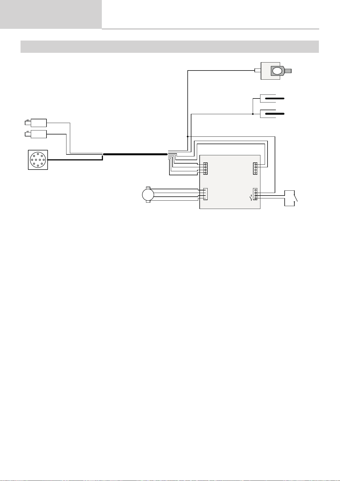
Schéma électrique
ELECTRICAL DIAGRAM / STROMLAUFPLAN
51459
51459
30
l
20
M
Pink
Grey
White
Brown
Yellow
Green
ARCPULL 350
29
29
1
2
3
4
6
7
21
N
Red
R
24
94

Pièces de rechange
SPARE PARTS / ERSATZTEILE
ARCPULL 350
22
27
23
21
28
24
20
26
25
30
29
29
20 Moteur / Motor / Motore / Мотор 71832
Si fabrication avant 05/2022
Carte électronique / Electronic board / Steuerplatine / Placa electrónica /
21
Электронная плата / Printplaat / Scheda elettrica
If manufactured before 05/2022
Si fabrication après 05/2022
If manufactured after 05/2022
22 Plot de masse / Ground stud / Massestift / Parcela de masa / Массовый участок / Grond Perceel /
Perno di terra
23 Ressort de tiges / Rod spring / Feder für Massekontaktstift / Muelles de varillas / Пружина штырей / Veer / Molla
ssa aste
S81143
E0151C
059627
55234 (x2)
24 Gâchette / Trigger / Schalter / Gatillo / Триггер/ Auslöser / Pulsante di avanzamento 56029
95

Pièces de rechange
ARCPULL 350
25 Bague de vérouillage / Locking nut / Verriegelungsring / Anilla de bloqueo / Кольцо блокировки / Vergrendelring
/ Anello di blocco
26 Coque avant / Front cover / Schale vorne / Frontal /
Voorzijde / Frontale
27 Molette de verrouillage des tiges / Earth rods locking wheel / Feststellknopf / Ruedecilla de bloqueo de varillas /
Передняя панель Колесико блокировки штырей / Vergrendelwieltje pinnen / Manopola di blocco aste
28 Coque arrière / Rear cover / Schale hinten / Posterior / Задняя оболочка / Achterschaal / Guscio posteriore 56189
29 Fiche Texas H14 Mâle / Texas plug H14 Male / Texas-Stecker H14 männlich / Enchufe Texas H14 Macho /
Техасский штекер H14 Мужской / Texas stekker H14 Mannelijk / Spina Texas H14 maschio
Faisceau complet sans pistolet / Complete bundle without gun / Komplettes
30*
Bündel ohne Pistole / Paquete completo sin pistola / Полный комплект без
пистолета / Complete bundel zonder pistool / Pacchetto completo senza pistola
* comprend toute la partie grisée sur le schéma / includes all the grey part on the diagram / enthält alle grauen Teile des Diagramms / incluye toda la parte gris en el diagrama / включает в себя
всю серую часть на схеме / bevat al het grijze gedeelte op het diagram / include tutta la parte grigia del diagramma.
SN < 23.05.xxxxxx.xxxxxx : contacter le SAV 56188
SN <23.09.xxxxxx.xxxxxx
SN >23.09.xxxxxx.xxxxxx S81106
90598
56270
51523 (x2)
contacter SAV
contact After-sales
service
96

Spécications
Techniques
TECHNICAL SPECIFICATIONS / TECHNISCHE SPEZIFIKATIONEN
Primaire / Primary / Primär
Tension d’alimentation / Power-supply voltage / Versorgungsspannung U1 230 V +/- 15%
Fréquence secteur / Mains frequency / Netzfrequenz 50 / 60 Hz
Fusible disjoncteur / Circuit breaker fuse / Sicherung Schutzschalter 16 A
Secondaire / Secondary / Sekundär
Tension à vide / No-load voltage / Leerlaufspannung U0 100 V
Courant de sortie nominal / Nominal output current / Nennausgangsstrom I2
Tension de sortie conventionnelle / Conventional output voltage / Nennausgangsspannung U2
* Facteur de marche à 40°C (10 min), Norme EN60974-1 / Duty cycle at 40°C (10 min), Standard EN60974-1.
Einschaltdauer bei 40 °C (10 Min), Standard EN60974-1
Imax 100 %
ARCPULL 350
ARCPULL 350
10 350 A
20,4 34 V
Température de fonctionnement / Operating temperature / Betriebstemperatur
Température de stockage / Storage temperature / Lagertemperatur
-10°C +40°C
-20°C +55°C
Degré de protection / Protection rating / Schutzgrad IP33
Dimensions (Lxlxh) / Dimensions (L x W x H) / Abmessungen (L x B x H) 23 x 31 x 28,4 cm
Poids générateur / Machine weight / Gewicht Stromquelle 11 kg
Pistolet / Gun / Pistole
Longueur du faisceau / Cable length / Länge Schlauchpacket 3 m
Poids pistolet / Gun weight / Gewicht Pistole 3 kg
*Les facteurs de marche sont réalisés selon la norme EN60974-1 à 40°C et sur un cycle de 10 min.
Lors d’utilisation intensive (supérieur au facteur de marche) la protection thermique peut s’enclencher, dans ce cas, l’arc s’éteint et le témoin s’allume.
Laissez l’appareil alimenté pour permettre son refroidissement jusqu’à annulation de la protection.
La source de courant de soudage décrit une caractéristique de sortie tombante.
*The duty cycles are performed according to standard EN60974-1 at 40°C and over a 10 minute cycle.
When used intensively (above the duty cycle) the thermal protections may be activated, in which case the arc will be extinguished and the indicator light will come on.
Leave the device connected to the power supply to allow it to cool down until the protective measures are no longer active.
The welding power source displays a declining output prole.
*Die Lauffaktoren werden gemäß EN60974-1 bei 40 °C und einem 10-minütigen Zyklus durchgeführt.
Bei intensivem Gebrauch (über der Einschaltdauer) kann der Wärmeschutz aktiviert werden; in diesem Fall erlischt der Lichtbogen und die Kontrollleuchte geht an.
Lassen Sie das Gerät eingeschaltet, damit es sich abkühlen kann, bis der Schutz aufgehoben wird.
Die Schweißstromquelle beschreibt eine fallende Ausgangscharakteristik.
97

Pictogrammes
SYMBOLS / ZEICHENERKLÄRUNG
FR
Attention ! Lire le manuel d’instruction avant utilisation. EN Warning ! Read the user manual before use. DE ACHTUNG !
Lesen Sie diese Anleitung sorgfältig durch vor Inbetriebnahme des Geräts.
FR
Symbole de la notice EN User manual symbol DE Symbole in der Bedienungsanleitung
FR
Source de courant de technologie onduleur délivrant un courant continu. EN Undulating current technology based source
delivering direct curent. DE Invertergleichstromquelle.
FR
Soudage à l’arc tiré EN Pulled arc welding DE Lichtbogenschweißen
FR
Convient au soudage dans un environnement avec risque accru de choc électrique. La source de courant elle-même ne
doit toutefois pas être placée dans de tels locaux. EN Suitable for welding in an environment with an increased risk of electric shock. However this a machine should not placed in such an environment. DE Geeignet für Schweißarbeiten im Bereich
mit erhöhten elektrischen Risiken.
FR
Courant de soudage continu EN Direct welding current DE Gleichschweißstrom
U0
X(40°C)
I2
A
U2
V
Hz
1~ 50/60 Hz
U1
I1max
I1eff
IEC 60974-1
IEC 60974-10
Class A
FR
Tension assignée à vide EN Open circuit voltage DE Leerlaufspannung
FR
Facteur de marche selon la norme EN60974-1 (10 minutes – 40°C). EN Duty cycle according to standard EN 60974-1
(10 minutes – 40°C). DE Einschaltdauer: 10 min - 40°C, richtlinienkonform EN60974-1.
FR
Courant de soudage conventionnel correspondant EN Corresponding conventional welding current DE Entsprechender
Schweißstrom
FR
Ampères EN Amperes DE Ampere
FR
Tensions conventionnelles en charges correspondantes EN Conventional voltage in corresponding loads. DE
Entsprechende Arbeitsspannung.
FR
Volt EN Volt DE Volt
FR
Hertz EN Hertz DE Hertz
FR
Alimentation électrique triphasée 50 ou 60Hz EN Three-phase power supply 50 or 60Hz DE Dreiphasige Netzversorgung
mit 50 oder 60Hz.
FR
Tension assignée d’alimentation EN Assigned voltage DE Netzspannung.
FR
Courant d’alimentation assigné maximal (valeur efcace) EN Maximum rated power supply current (effective value). DE
Maximaler Versorgungsstrom
FR
Courant d’alimentation effectif maximal. EN Maximum effective power supply current. DE Maximaler effektiver Versorgungsstrom
FR
Matériel conforme aux Directives européennes. La déclaration UE de conformité est disponible sur notre site (voir à la
page de couverture). EN Device complies with europeans directives, The EU declaration of conformity is available on our
website (see cover page). DE Gerät entspricht europäischen Richtlinien. Die Konformitätserklärung nden Sie auf unsere
Webseite.
FR
Matériel conforme aux exigences britanniques. La déclaration de conformité britannique est disponible sur notre site
(voir à la page de couverture). EN Equipment in compliance with British requirements. The British Declaration of Conformity
is available on our website (see home page). DE Das Gerät entspricht den britischen Richtlinien und Normen. Die Konformitätserklärung für Grossbritannien ist auf unserer Internetseite verfügbar (siehe Titelseite).
FR
Matériel conforme aux normes Marocaines. La déclaration Cم (CMIM) de conformité est disponible sur notre site (voir
à la page de couverture). EN Equipment in conformity with Moroccan standards. The declaration Cم (CMIM) of conformity
is available on our website (see cover page). DE Das Gerät entspricht die marokkanischen Standards. Die Konformitätserklärung Cم (CMIM) ist auf unserer Webseite verfügbar (siehe Titelseite).
FR
L’appareil respecte la norme EN60974-1 et EN60971-10 appareil de classe A. EN The device is compliant with standard
EN60974-1 and EN60971-10 class A device. DE Das Gerät erfüllt die Norm EN 60974-1 und EN 60971-10 der Geräteklasse A
FR
Ce matériel faisant l’objet d’une collecte sélective selon la directive européenne 2012/19/UE. Ne pas jeter dans une poubelle domestique ! EN This hardware is subject to waste collection according to the European directives 2012/19/EU. Do not
throw out in a domestic bin ! DE Für die Entsorgung Ihres Gerätes gelten besondere Bestimmungen (sondermüll) gemäß
europäische Bestimmung 2012/19/EU. Es darf nicht mit dem Hausmüll entsorgt werden!
FR
Produit recyclable qui relève d’une consigne de tri. EN This product should be recycled appropriately DE Recyclingprodukt, das gesondert entsorgt werden muss.
FR
Marque de conformité EAC (Communauté économique Eurasienne) EN EAEC Conformity marking (Eurasian Economic
Community). DE EAC-Konformitätszeichen (Eurasische Wirtschaftsgemeinschaft)
ARCPULL 350
98

Pictogrammes
ARCPULL 350
FR
Information sur la température (protection thermique) EN Temperature information (thermal protection) DE Information zur
Temperatur (Thermoschutz)
FR
Entrée de gaz EN Gas input DE Gaseingang
FR
Sortie de gaz EN Gas output DE Gasausgang
FR
Commande à distance EN Remote control DE Fernregler
99

GYS France
Siège social / Headquarter
1, rue de la Croix des Landes - CS 54159
53941 Saint-berthevin Cedex
France
GYS Italia
Filiale / Filiale
Via Porta Est, 7
30020 Marcon - VE
Italia
www.gys.fr
+33 2 43 01 23 60
service.client@gys.fr
GYS UK
Filiale / Subsidiary
Unit 3
Great Central Way
CV21 3XH - Rugby - Warwickshire
United Kingdom
www.gys-welding.com
+44 1926 338 609
uk@gys.fr
GYS GmbH
Filiale / Niederlassung
Professor-Wieler-Straße 11
52070 Aachen
Deutschland
www.gys-schweissen.com
+49 241 / 189-23-710
aachen@gys.fr
www.gys-welding.com
+39 041 53 21 565
italia@gys.fr
GYS China
Filiale / 子公司
6666 Songze Road,
Qingpu District
201706 Shanghai
China
www.gys-china.com.cn
+86 6221 4461
contact@gys-china.com.cn
GYS Iberica
Filiale / Filial
Avenida Pirineos 31, local 9
28703 San Sebastian de los reyes
España
www.gys-welding.com
+34 917.409.790
iberica@gys.fr
 Loading...