

Gyrotonic TRANSFORMER 1500 Owner's Manual
This Product is Produced Exclusively by
2040 N. Alliance, Springfield, MO 65803
Customer Service Number
1 (800) 375-7520
www.staminaproducts.com
& Logo and are trademarks of Gyrotonic Sales Corporation.
2003, 04
Owner's Manual
NOTE: Assembly Instructions are also included in
the Video. Fast Forward the video to the end on the
workout portion to find the assembly instructions.
! WARNING !
Exercise can present a health
risk. Consult a physician
before beginning any exercise
program with this equipment.
If you feel faint or dizzy,
immediately discontinue use
of this equipment. Serious
bodily injury can occur if this
equipment is not assembled
and used correctly. Serious
bodily injury can also occur if
all instructions are not
followed. Keep others and
pets away from equipment
when in use. Always make
sure all bolts and nuts are
tightened prior to each use.
Follow all safety instructions in
this manual.
When calling for parts or
service, please specify the
following number.
CAUTION:
Weight on this product should not exceed 300 lbs.
55-6150
PATENT NO. 4,850,586
OTHER P ATENTS PENDING
MADE IN T AIW AN
Product May Vary Slightly
From Pictured.

TABLE OF CONTENTS
2
Warm-up and Cool-Down 14
Warranty 15
Product Parts Drawing 16
Parts List 17
Notes 19
Fax/Mail Ordering Form 22
Page Page
Safety Instructions 2
Before You Begin 4
Hardware Illustrations 5
Assembly Instructions 6
Usage Information 10
Conditioning Guidelines 13
Before starting any exercise or conditioning program you should consult with your personal
physician to see if you require a complete physical exam. This is especially important if you
are over the age of 35, have never exercised before, are pregnant, or suffer from any
illness. READ AND FOLLOW THE SAFETY PRECAUTIONS. FAILURE TO FOLLOW
THESE INSTRUCTIONS CAN RESUL T IN SERIOUS BODILY INJURY.
SAFETY INSTRUCTIONS
WARNING: To reduce the risk of serious injury, read the following Safety Instructions before
using the TRANSFORMER
TM
1500.
Read all warnings posted on the TRANSFORMER
TM
1500.
Read this Owner's Manual and follow it carefully before using the TRANSFORMER
TM
1500. Make
sure that it is properly assembled and tightened before use.
Do not allow children to play on the TRANSFORMER
TM
1500. Keep children and pets away from
the TRANSFORMER
TM
1500 when it is in use by others. Children should only be allowed to use the
product with adult supervision.
Set up and operate the TRANSFORMER
TM
1500 on a solid level surface. Do not position the
TRANSFORMER
TM
1500 on loose rugs or uneven surfaces.
Inspect the TRANSFORMER
TM
1500 for worn or loose components prior to use.
Tighten/replace any loose or worn components prior to using the TRANSFORMER
TM
1500.
When folding or unfolding the TRANSFORMER
TM
1500, keep all children away from the
TRANSFORMER
TM
1500 and make sure your hands are clear of any folding or pinch point.
Always make sure that the LOCKING PIN(37), EYEBOL T(39), and SNAP PIN(95) are properly installed.
Before folding the bench down, make sure that all three WHEELS(8) are up in the non-rolling position.
Consult a physician prior to commencing an exercise program. If, at any time during exercise, you
feel faint, dizzy, or experience pain, stop and consult your physician.
Follow your physician's recommendations in developing your own personal fitness program.
Always choose the workout which best fits your physical strength and flexibility level. Know your
limits and train within them. Always use common sense when exercising.
Do not wear loose or dangling clothing while using the TRANSFORMER
TM
1500.
Be careful to maintain your balance while using, mounting, dismounting, or assembling the
TRANSFORMER
TM
1500, loss of balance may result in a fall and serious bodily injury.
The TRANSFORMER
TM
1500 should not be used by persons weighing over 300 pounds.
The TRANSFORMER
TM
1500 should be used by only one person at a time.
The TRANSFORMER
TM
1500 is for consumer use only. It is not for use in public or semipublic
facilities.
WARNING:
1.
2.
3.
4.
5.
6.
7.
8.
9.
10.
11.
12.
13.
14.
15.
16.
17.

CALL US FIRSTCALL US FIRST
CALL US FIRSTCALL US FIRST
CALL US FIRST
THANK YOU FOR PURCHASING THE
TRANSFORMER
TM
1500
To help you get started, we have pre-assembled most of your
TRANSFORMER
TM
1500 at the factory with the exception
of those few parts left unassembled for shipping purposes.
Simply follow the few assembly instructions set forth in this manual.
Within a few minutes you will be getting your body into shape and on your
way to achieving a happier and healthier lifestyle.
Should you have any questions,
please call our Customer Service Department toll-free number,
1 (800) 375-7520
Monday - Friday, 8:00 A.M. - 5:00 P.M., Central Time.
3
BEFORE YOU BEGIN
THE FOLLOWING TOOLS ARE REQUIRED FOR ASSEMBLY :
4
Thank you for choosing the
TRANSFORMER
TM
1500. We take great pride in producing this quality
product and hope it will provide many hours of quality
exercise to make you feel better, look better and
enjoy life to its fullest.
Y es, it's a proven fact that a regular exercise program
can improve your physical and mental health. Too
often, our busy lifestyles limit our time and opportunity
to exercise. The
TRANSFORMER
TM
1500 provides
a convenient and simple method to begin your assault
on getting your body in shape and achieving a happier
and healthier lifestyle.
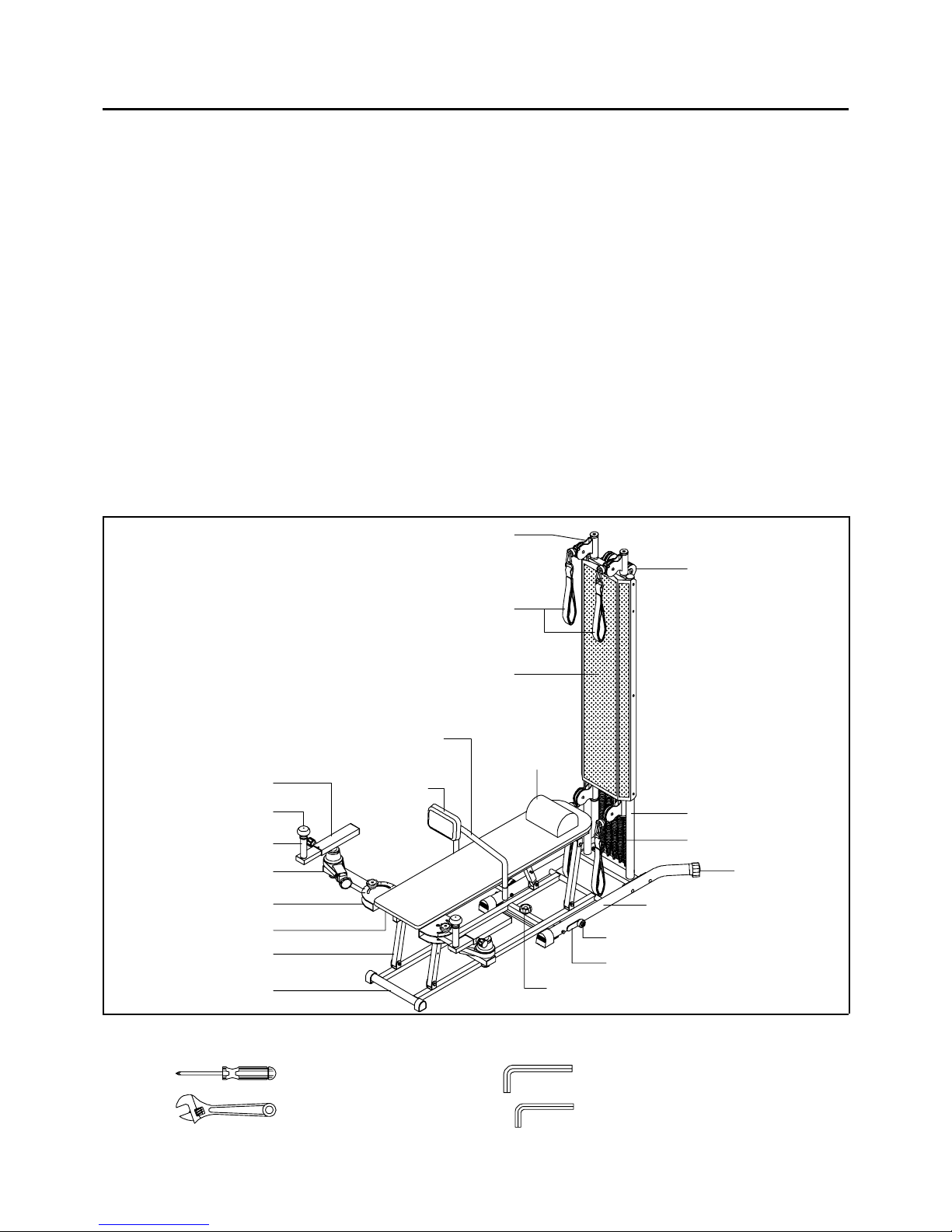
Before reading further , please review the drawing
below and familiarize yourself with the parts that are
labeled.
Read this manual carefully before using the
TRANSFORMER
TM
1500.
Although Stamina tries to manufacture its products
with the finest materials and uses the highest
standards of manufacturing, occasionally a part that
does not fit, is the incorrect size, or is otherwise
inappropriate is found. Even with the highest
inspection and quality controls in place these things
will happen occasionally. Please do not return the
product. For your convenience, Stamina has a
Customer Service Department with a toll-free
number. If a part is missing, does not fit, is the
incorrect size, or is otherwise inappropriate, please
call 1 (800) 375-7520 (in the U.S.) between 8:00 A.M.
and 5:00 P.M. Central Time, Monday through Friday .
Our operators will be able to assist you with your
problem and the parts will be mailed directly to your
house.
Bench Leg
Right Arm Frame
Right Support Arm
Hand Grip
Handle Knob
Right
Rotating Arm
Cushion
Bench Base
Pulley Frame
Hand Straps
Pulley
Lower Upright
Springs
Wheel
Pivot Plate
Securing Knob
Upright Guard
Back
Cushion
Left Base
Back Cushion
Support
Pillow
Leveling Cap
Allen Wrench (6mm)
Allen Wrench (5mm) (2 Required)
Phillips Screwdriver
Adjustable Wrench
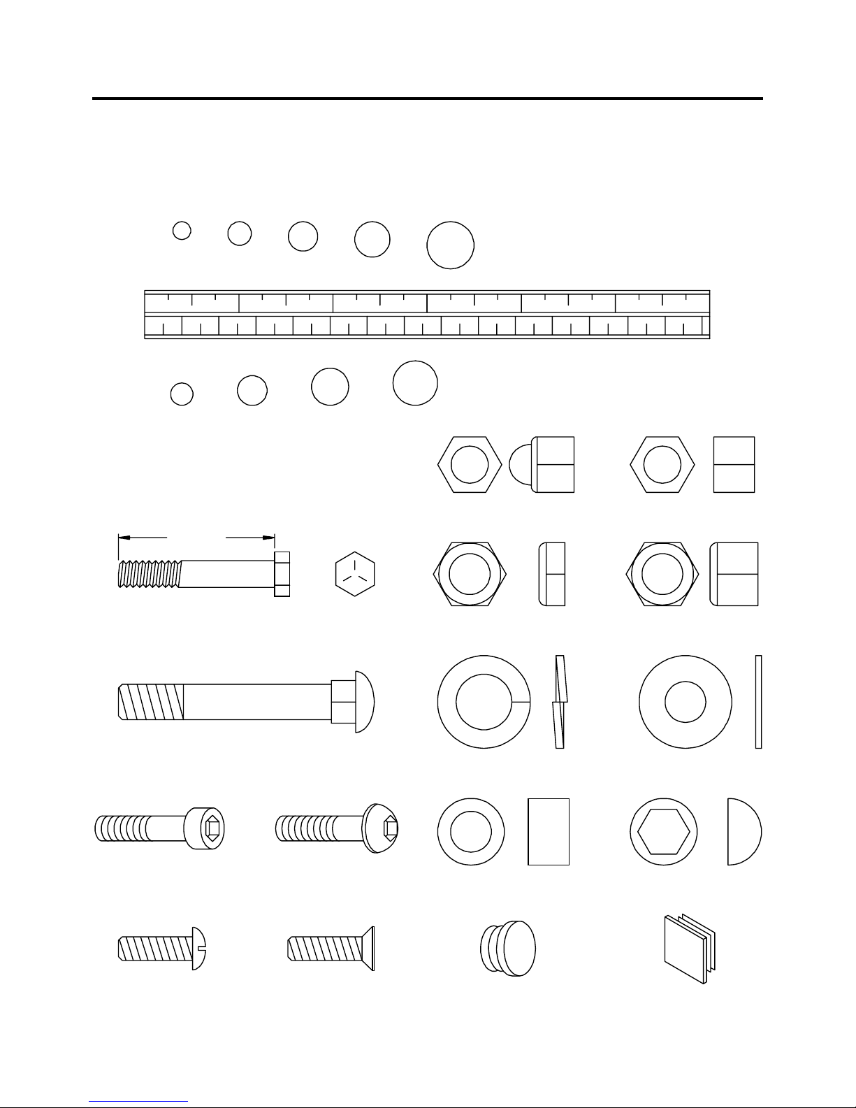
This chart is provided to help identify some of the small parts used in the assembly of this product. This
sheet may not include all the hardware needed to assemble your product. It is intended to be used as a
guide to help simplify your assembly process.
Standard Nut
mm.
in.
INCHES
MILLIMETERS
11/2021/2 31/2 41/2 51/2 61/2
0 10 20 30 40 50 60 70 80 90 100 110 120 130 140 150
6 8 10 12
3/16" 5/16" 1/2"3/8"1/4"
Acorn Nut
Thin Nylock Nut Nylock Nut
Flat WasherLock Washer
Nut CapSpacer
Round Plug Square Plug
Hex Head Bolt
Length
Carriage Bolt
Socket Head Screw Button Head Screw
Round Head Screw Flat Head Screw
Place washers, the end of bolts or screws on the
circles to check for the correct size. Use the small
scale to check the sizes of bolts and screws.
HARDWARE ILLUSTRATIONS
5
ASSEMBLY INSTRUCTIONS
Assembly Instructions are also included in the Video. Fast Forward the video to the
end on the workout portion to find the assembly instructions.
NOTE:
Place all parts from the box in a cleared area and position them on the floor in front of you. Remove all
packing materials from your area and place them back into the box. Do not dispose of the packing materials
until assembly is completed. Read each step carefully before beginning. If you are missing a part please
call our toll-free number for assistance 1 (800) 375-7520 or e-mail us at: parts@staminaproducts.com
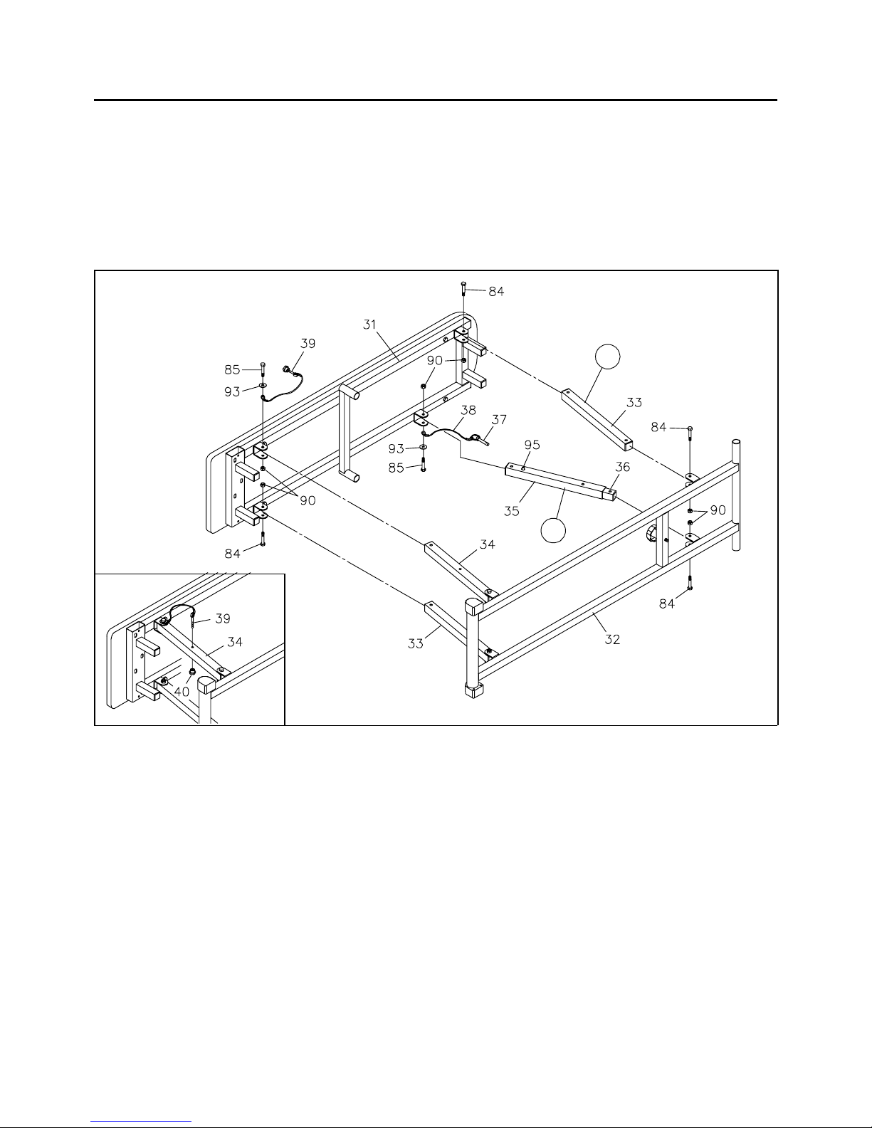
BACK
NOTE: There is a "L" decal on the BENCH LEG(33), and a "R" decal on the SUPPORT TUBE(35)
and INNER SUPPORT TUBE(36) assembly to help you identify their positions on the frame.
STEP 1: Set the BENCH BASE(32) on the floor as shown in the illustration above. Attach the two
BENCH LEGS(33) to the BENCH FRAME(31) and the BENCH BASE(32) with HEX BOLTS
(M8 x 45mm)(84) and NYLOCK NUTS(M8)(90).
STEP 2: Attach the BENCH LEG/w HOLE(34) and EYEBOLT(39) to the BENCH FRAME(31) with
HEX BOLT(M8 x 50mm)(85), WASHER(M8)(93), and NYLOCK NUT(M8)(90). Store the
EYEBOLT(39) by Inserting the EYEBOLT(39) into the hole on the BENCH LEG/w HOLE(34) and
secure with the
SMALL KNOB(40). Refer to the inset drawing.
STEP 3: Attach the SUPPORT TUBE(35) and LOCKING PIN(37) to the BENCH FRAME(31) with
HEX BOLT(M8 x 50mm)(85), WASHER(M8)(93), and NYLOCK NUT(M8)(90). Attach the INNER
SUPPORT TUBE(36) to the BENCH BASE(32) with HEX BO LT(M8 x 45mm)(84) and NYLOCK
NUT(M8)(90).
NOTE: If the SUPPORT TUBE(35) and the INNER SUPPORT TUBE(36) are locked together by the
SNAP PIN(95) during assembly, press the SNAP PIN(95) down to release the tubes.
6
FRONT
L
R
ASSEMBLY INSTRUCTIONS
7
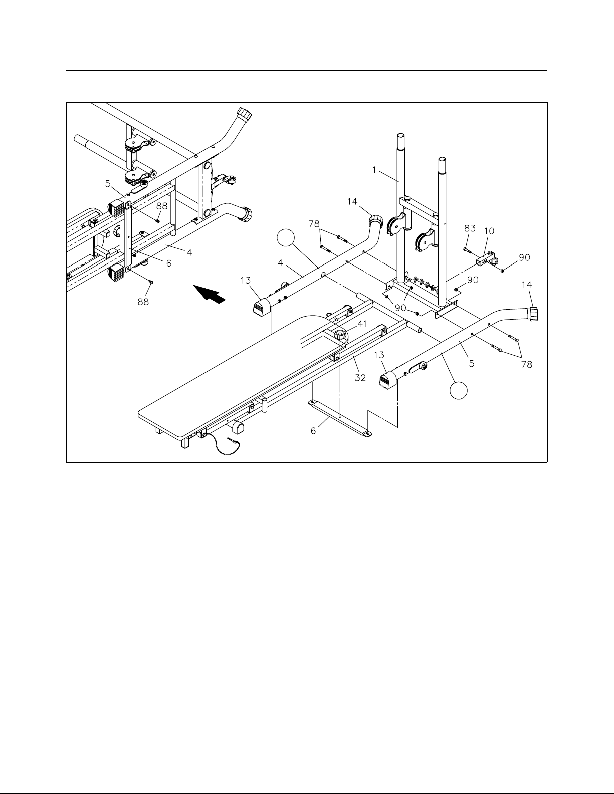
NOTE: There is a "L" decal on the LEFT BASE(5), and a "R" decal on the RIGHT BASE(4) to help
you identify their positions on the frame.
STEP 4: Place the BENCH upright in the folded position as shown above. Attach the RIGHT BASE(4)
onto the LOWER UPRIGHT(1) with CARRIAGE BOLTS(M8 x 65mm)(78) and NYLOCK
NUTS(M8)(90). Do not tighten until STEP 6.
STEP 5: Insert the round tube on the BENCH BASE(32) into the holes on the RIGHT and LEFT
BASES(4, 5), then attach the LEFT BASE(5) onto the LOWER UPRIGHT(1) with CARRIAGE
BOLTS(M8 x 65mm)(78) and NYLOCK NUTS(M8)(90). Do not tighten until STEP 6.
STEP 6: Slide the CROSS BAR(6) under the RIGHT and LEFT BASES(4, 5) and attach the CROSS
BAR(6) to the BENCH BASE(32) with the SECURING KNOB(41). Lay the FRAME ASSEMBL Y on
the floor as shown in the illustration above. Attach the
CROSS BAR(6) to the RIGHT and LEFT BASES
(4, 5) with BUTTON HEAD BOL TS(M8 x 16mm)(88). Stand the FRAME ASSEMBL Y upright. T ighten
NYLOCK NUTS(90) in STEPS 4 and 5. Adjust the ENDCAPS(13) and LEVELING CAPS(14) so
that the
FRAME ASSEMBLY sets flat on the floor.
STEP 7: Attach the WHEEL SUPPORT(10) onto the LOWER UPRIGHT(1) with HEX BOLT
(M8 x 40mm)(83) and NYLOCK NUT(M8)(90).
R
L
 Loading...