

Page 1

1
GASENGINES “V2”
CLASSIC
ASSEMBLY PLAN
Page 2
2
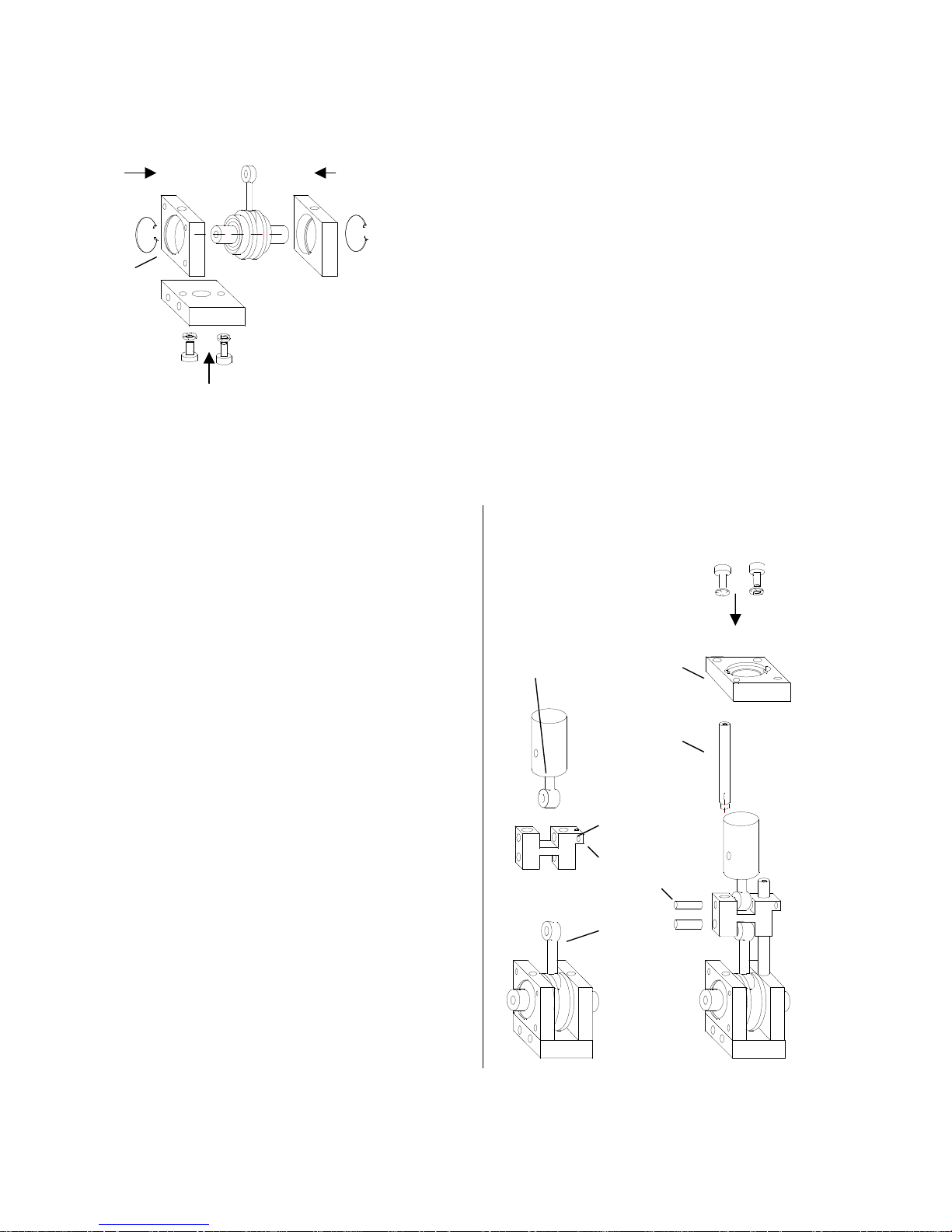
2. Mounting the crosshead guide
2.1 Firmly fasten the right guide rod (6) with M4
threads on the bearing plate.
2.2 Fit the crosshead (9) into the guide rod (6),
ensure that the M3 connection is on the right.
(s. sketch)
2.3 Fit the connecting rod (7) with cylinder pin (9.1)
and piston rod (8) in the crosshead.
2.4 Push the second guide rod (6) through the crosshea
d
and fasten it on the bearing plate
2.5 Fasten the cylinder plate (3) with M3 screws and
retaining rings onto the guide rods; the piston must
fit through the centre hole.
When fastening, the crosshead the top position
should be next to the cylinder plate.
2.6 Push the crosshead downwards to the bearing plates
and then loosen the M3 screw once again and then
retighten.
The crosshead must easily move to-and-fro,
(thermal expansion).
Finally tighten all screws.
8 3
6
9
M3
9.1
7
ASSEMBLY PLAN
Component parts are to some extent fitted together as
subassemblies.
1. Mounting the crankshaft bearing
1.1 Fit the short crankshaft with both bearings in the
bearing plate (4).
(In case of resistance, you have to support the
crankshaft in the middle)
1.2 Allow the lock washers (4.1) to snap into the
grooves on the outside of the bearing plates.
(s. sketch)
1.3 Loosely screw the base plate (5) with two M3
screws and retaining rings.
Page 3
3
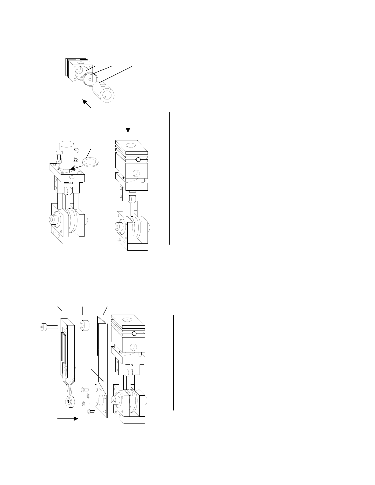
3. Mounting the cylinder unit
3.1 Insert the Teflon seal (2.1) into the cylinder housing
(2) (can be already fitted inside the housing)
3.2 Fit the cylinder (3) into the cylinder housing,
ascertain that exhaust openings correspond.
(sparkplug hole backwards)
3.3 The cylinder unit is now to be mounted on the
cylinder plate. (Screws M4x20.) First insert a feltring seal (F) into the cylinder plate, for lubrication.
3.4 Insert the piston into the cylinder and tighten the
screw crosswise.
3.5 Once again check the engine unit for smooth
running and if necessary eliminate strain.
4. Mounting the ignition holder
4.1 Fasten the ignition device holder mounting
bracket25.5 with 4 countersunk head screws on the
bearing plate.
4.2 Fasten the ignition device 25 with spacer washer
5.2 and M3 screw onto the holder mounting
bracket. Fix the M4 x10 set screw (25.3) with lock
nut in the mounting bracket.
2 2.1 3
F
25 25.2 25.5
25.3
Page 4
4
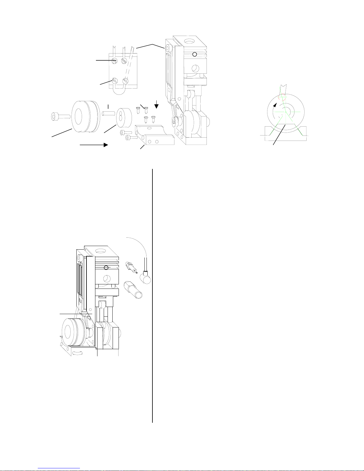
5. Mounting the ignition unit.
5.1 Mount the stator (22) on base plate (M3 x10).
5.2 Push the cable from ignition through the inclined hole on
the stator and guide it into the second hole (A).
5.3 Push two cables, (red) for the spark plugs, into the short
holes on the stator (B).
5.4 Drive in the four screws (22.2) completely through the
predrilled holes, the screws thereby penetrate the cables
insulation and establish the electrical contact.
5.5 Stick the pin (20.1) (1.5x 13) into the hole in
the crankshaft.
5.6 Push the eccentric cam (20) over the pin.
5.7 Fasten the rotor (21) with screw (M4 x 30) through the
eccentric cam (20) on the crankshaft.
The rotor is to be positioned and fastened such that the
"bridge" inside the rotor lies downwards above the screws
(22.2) - when the crankshaft has nearly reached the top dead
centre (approx. 3 degrees earlier), (c) - so that high-voltage
sparking occurs.
5.8 Fasten the sparkplug (23/24) tightly on the cylinder housing
and then fix the red cable with cap.
5.9 Unscrew the exhaust (47).
5.10 Drive in the screw M4 (25.3) into the bracket so deeply onto
the ignition that when rotating the crankshaft the highvoltage sparks over on the rotor.
The sparkplug should be checked through
the carburettor opening because the
sparkplug is no longer tight if the plastic
part is repeatedly unscrewed.
Ignition
Sparkplug 2
Sparkplug 1
B
A
20.1 22.2
21 20
22
View from the flywheel side
c
"Bridge"
Timing
Sparkplug
25.3
Page 5
5
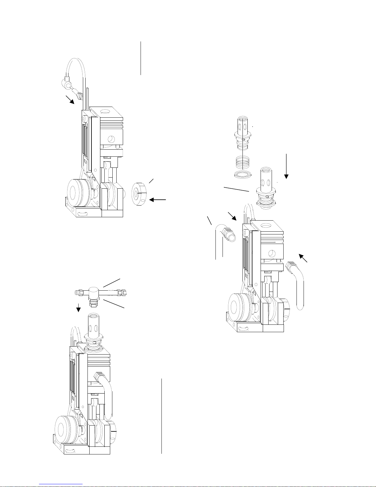
6 Mounting the clutch
6.1 Fit the clutch (50) on the free shaft end and fasten it with
M6 x 10 screws.
7. Mounting the carburettor unit
7.1 Screw in the carburettor pipe (15) with a mounted valve
into the cylinder housing and tighten (M10x1) gas-tight,
for this, stick a pin or screwdriver through the openings.
7.2 Open the mounted gas valve (25) and lock with lock nut
(29).
50
15
47
28
29
Page 6
6
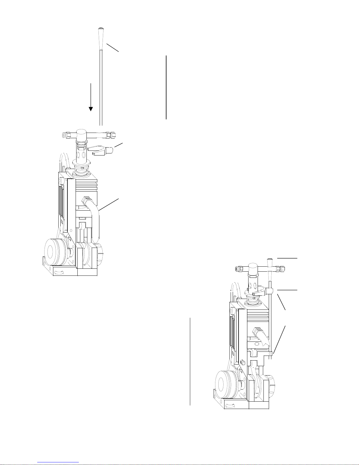
8. Mounting the valve control
Screw in the stud bolt M3 into the threaded
hole in the crosshead.
8.2 Guide the control lever with tapered end
(31) through the hole on gas valve.
8.3 Push the catch (32) over the control lever.
8.4 Fasten the control lever in the crosshead with
M3 screws.
8.5
Fasten the catch on the control lever (M3) such
hat when the crankshaft is at the bottom dead
centre, the valve spring 2/3 is compressed.
(From the top of control lever approx.
38 mm.)
8.6 Mount the exhaust pipes (47)
31
32
M3
Approx.
36mm
M3
Page 7

7
9. Assemble the second engine
9.1 Proceed logically as explained in
1.1 to 3.4, however, mount the crosshead with
valve connection on the left and spark plug hole in
the cylinder, and lubrication hole in the cylinder
plate forward.
9.2 Fasten the flywheel (14) on the
crankshaft end with M6 thread
connection (for CL with the belt
pulley)
10. Mounting the carburettor unit
10.1 Screw in the carburettor pipe with a mounted valve in
the cylinder housing. To tighten, stick a pin through the
openings.
10.2 Unscrew the mounted gas valve with lock nut and
tighten with the lock nut.
10.3 Mount the valve rod as described in 8.1 to 8.6
10.4 Mount the exhaust pipe.
14
Page 8
8
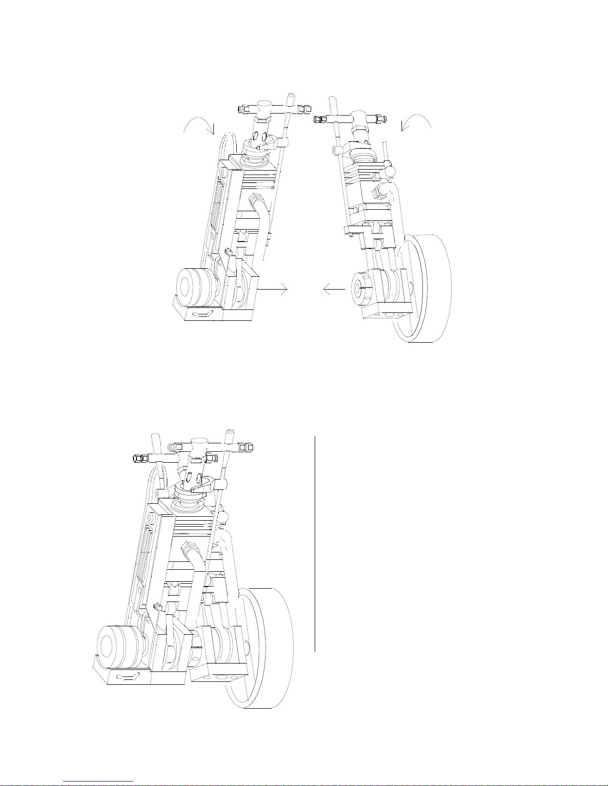
11. Assembly
11.1 Join the engine with free shaft end (s. sketch)
into the clutch of the second engine.
11.2 Screw the engine on the prism (51).
11.3 Rotate both crankshafts such that the right
engine is at the top dead centre and the left at the
bottom dead centre.
11.4 Tighten the screw in the clutch in this position.
11.5 Screw the engine unit on the prism loosely.
11.6 Rotate the engine and check for strain and then
tighten the screws.
11.7 Fix the ignition cable on the spark plugs.
Page 9
9
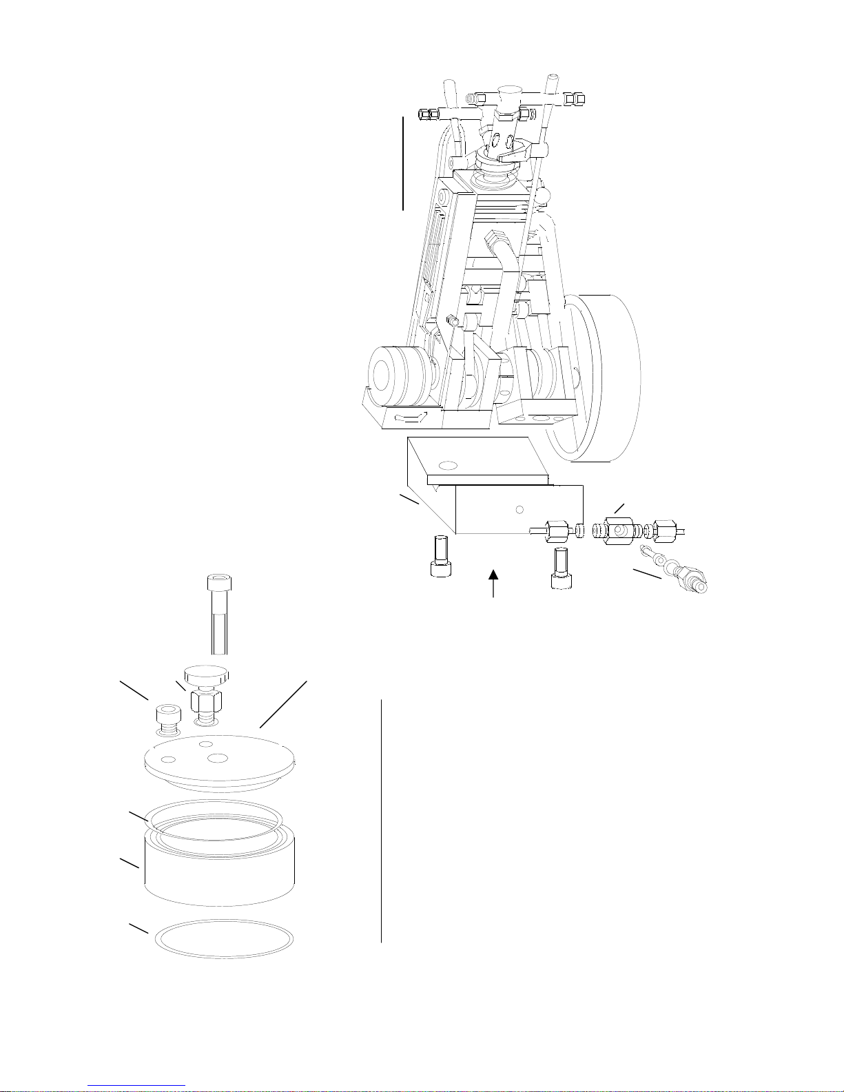
12. Mounting the gas distributor
12.1 Fasten the distributor (49) with M3 screws
and screw the seal on the prism (51)
13.2 Screw in the connection nipple (49.1 )
with seal in the distributor.
13. Mounting the tank
13.1 Însert the seals into the grooves of tank ring (42).
13.2 Screw the gas tank cap (42.3) and ring with M6 screws
and seal washers (42.1) on the base plate
13.3 Screw in the gas tank valve (37) and gas control valve (41)
with the seals inside gas tank cap, taking care of the
position of gas connection. (For adjustment, the tank cap
can also be screwed.)
13.4 Tighten the tank cap
13.5 Check the tank for air-tightness.
51 49
49.1
37 41 42.3
42.1
42
42.1
Page 10
10
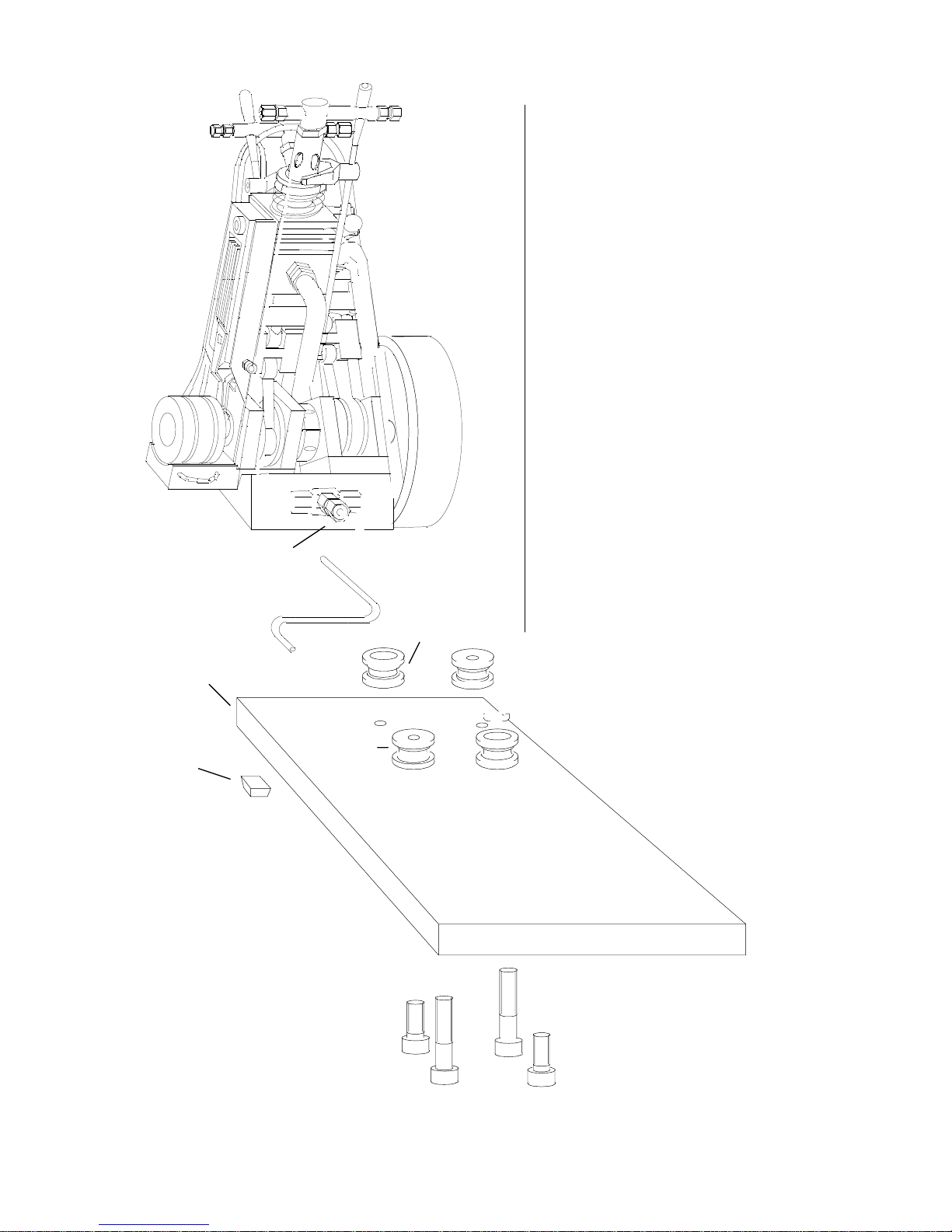
14. Mounting the engine on base plate
14.1 Fasten two stands with threads (45) using
short screws (45.1) on the base plate.
14.2 With two further stands (45.2) and the long
screws, screw the engine unit with the
prism onto the base plate.
14.3 Glue four legs (43.2) from the bottom on
the base plate.
15. Mounting the gas pipes
15.1 Mount prefabricated gas lines with union
nuts (36) and seals on the distributor (49)
and then mount on the two gas valves (28).
15.2 Connect the gas line to the tank and
distributor.
36
45.1
43
43.2 45.2
Page 11
11
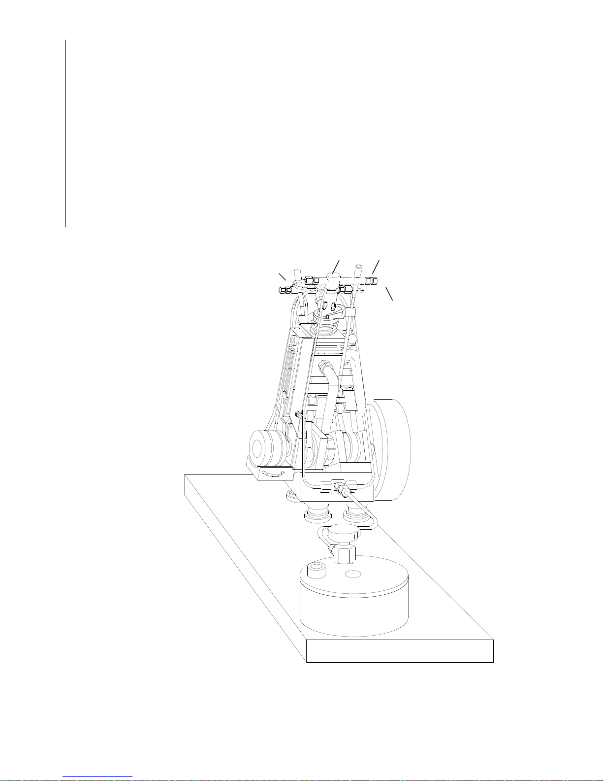
16. Putting into operation and tuning
16.1 Check ignition once again
Ignition spark must flash approx. 3 degrees prior to the top dead centre of both
crankshafts. Corrective measures can be taken for the left cylinder via the
position of the rotor (21), and the right cylinder can be adjusted via the clutch
(50).
16.2 Open the gas valve on gas tank and check lines for gas-tightness.
16.3 On both gas valves (28), screw in the setting screw (34) into the valve, far
enough until gas flows out of the nozzle at the bottom dead centre of the
crankshaft.
16.4 Start the engine by rapidly rotating the flywheel clockwise, for instance, with
the thumb and index finger on the spoke or depending upon model, on the
circumference with the palm.
16.5 Tune both engines with the setting screws (34) to the same rotational speed and
then tighten with the lock nuts (34.1).
16.6 The desired rotational speed of the engine
can now be regulated with gas valve on the tank.
Maintenance
Guide rods and the connecting rod bearing should be lubricated after a long period of operation.
Use oil without resin content to lubricate the piston through the hole inside the cylinder plate.
28 34
34
34.1
 Loading...