

The Ferret 953 adapts virtually any dual channel labscope or graphing multimeter to display
the parade pattern.
The quality of the ignition waveform depends on the performance of the labscope.
You must be familiar with the operation of the labscope being used with the Ferret 953. Please
the connectors plugged into each side of the Ferret 953. Use the polarity switches on the 953
to set the fi ring polarity the same (COP Ignitions), or each side different (DIS Ignitions).
The Ferret 953 uses a 9-volt battery for power. Press the Power button once and the indicator
the Cylinder #1 Trigger (Ferret 951), and the Ferret 953 to the input channel by stacking the
synchronize the display to #1 Cylinder. To analyze Cylinder #1, move the Ferret 951 Cylinder
All instructions remain the same, except you connect only one KV Clip to the Coil wire. Do not
Available Accessories
X020-44 KV Pickup Plate for GM HEI Internal Coil Ignitions
X020-45 KV Pickup Plate for Toyota Internal Coil Ignitions
X020-46 KV Pickup Plate for Nipondenso Internal Coil Ignitions.
X015-05 KV Pickup Plate for BMW Coil per Plug Ignitions
Safety Precautions
Read all Instructions before using the device
• Always wear eye protection when testing vehicles. Be extra careful near
batteries and moving parts. Do not lay tools on a battery.
• Battery gas is highly explosive.
a. If a battery explodes fl ush the acid away from persons skin with generous
amounts of water. Follow up with a neutralizing solution of baking soda
and then more water.
Treat clothing, vehicle parts, and equipment similarly. Any acid traces
inside equipment must be removed by generous rinsing. Dry equipment
and place in a warm 50°C (120°F) oven until thoroughly dry.
b. Never use a wrench on the ungrounded battery terminal until the
grounded one has been disconnected. Contact between the vehicle
body metal and the hot terminal can cause sparks to ignite gas or even
weld tools into a battery short circuit.
c. Keep the space around a battery well ventilated.
d. Do not make sparks or allow fl ames near batteries.
• Before working on a vehicle set the brakes and block the wheels. Beware
of automatic parking brake releases.
• Keep your work area well ventilated and free of exhaust. Engine exhaust
contains deadly poisons. Treat Gas Detector exhaust and drain hoses the
same as the vehicle tailpipe. Both give off deadly exhaust fumes.
• Avoid electrical shocks caused by getting close to live ignition wires or
touching the coil TACH terminal. A person’s reaction near a live engine can
be more damaging than the shock.
• Keep spark producing devices at least 0.5m (18”) above the fl oor to reduce
the hazard of igniting gasoline vapor.
• Do not let test leads wind up in a moving fan or pulley. Route leads
away.
• Remove fi nger rings and metal wrist bands. They can short terminals and
become very hot from electric current.
Technical Support & Service
Technical Support & Service
Warranty
Toll Free (800) 627-5655.
When sending an item to the factory address it to:
This Warranty does not apply to products which have been altered outside the
factory; or repaired by anyone other than the factory or its authorized service
ARE NO OTHER WARRANTIES EXPRESSED OR IMPLIED INCLUD-
THE PRODUCT.
This warranty gives you specifi c legal rights and you may also have other
E953-01G
©Copyright 2005, GxT, Inc., All Rights Reserved
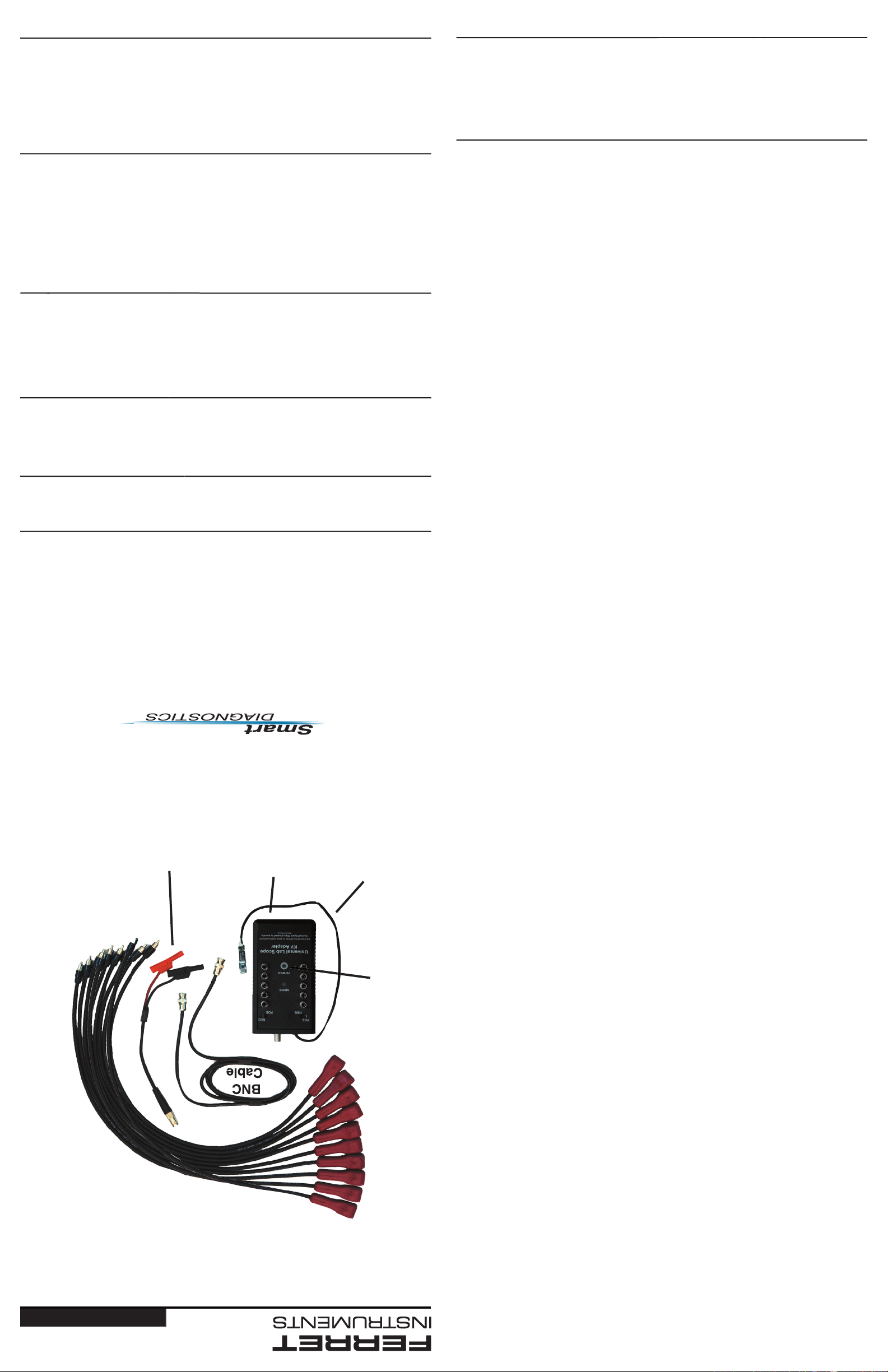
OPERATORʼS MANUAL
LabScope KV Adapter
953
BNC
Cable
BNC to Banana
Adapter
Battery
Compartment
Ground
Lead
Power
Button
KV
Clips
scope confi gured for a
4 stroke engine
4 stroke engine
2. Connect the Ground lead of the Ferret 953
to a good engine ground, and connect the KV Clips to each of the DIS sparkplug wires.
3. Plug the KV Leads to the Ferret 953 in pairs, one coil at a time. Plug one KV Lead to a
4. Start the engine, and adjust the scale of the display until a clear pattern is displayed. If the
spikes appear upside down on any pair of the cylinders, swap the KV Clips at the ignition
2. Connect the Ferret 953 to Channel 1 using the BNC to Banana
Adapter. You will need to piggyback or stack both Channel 1 and
the Common jack.
3. Connect the Ground lead of the Ferret 953 to a good engine
wires only. Do not plug the KV Leads into the Ferret 953.
4. Turn the Vantage on and select the Waveform Viewer. Select the
the other should be set to negative. Plug a KV Lead into the Ferret
2. Connect the Ferret 951 Cylinder #1 Trigger to Channel 1
3. Connect the Ferret 953 to Channel 2 using the BNC to
4. Turn the Scope on and Set Channel 1 to the 10 volt range,
20 milliseconds.
to each of the DIS sparkplug wires only. Do not plug the KV Leads into the Ferret 953.
2. Connect the Ferret 951 Cylinder #1 Trigger to the Red channel,
3. Connect the Ferret 953 to the Green channel.
4. Connect the Ground lead of the Ferret 953 to a good engine
wire only. Do not plug the KV Leads to the Ferret 953.
following parameters: 0.5 volts with a time base of 50ms.
for the trigger.
the other should be set to negative. Plug a KV Lead into the Ferret
2. Connect the Ferret 951 Cylinder #1 Trigger to Channel 1 using the BNC to Banana Jack
Adapter. Then connect the 951 to #1 Sparkplug wire.
3. Connect the Ferret 953 to Channel #2 using the BNC to Banana Jack Adapter. You will
4. Connect the Ground lead of the Ferret 953 to a good engine ground, and connect the KV
that tthis Labscope always triggers on Channel 1. The purpose of this setup is to trigger
to negative. Plug a KV Lead into the Ferret 953. If the labscope display shows an inverted
fi ring peak, plug the KV Lead into the other bank of connectors. Continue until all KV leads
The Ferret 953 will work with any dual trace labscope. The instructions below will give you
the steps necessary to get a basic ignition waveform on the screen. Use of other features
specifi c to your labscope may enhance the display of the pattern.
2. Set Channel 1 to the following parameters: DC Coupled, 0 to 5 volt range, time base of
3. Set Channel 1 to be the trigger with a positive slope. The trigger level should be about 4
volts.
4. Connect the Ferret 953 to Channel 2.
to each of the DIS spark plug wires only. Do not plug the KV Leads into the Ferret 953.
the other bank of connectors. Continue
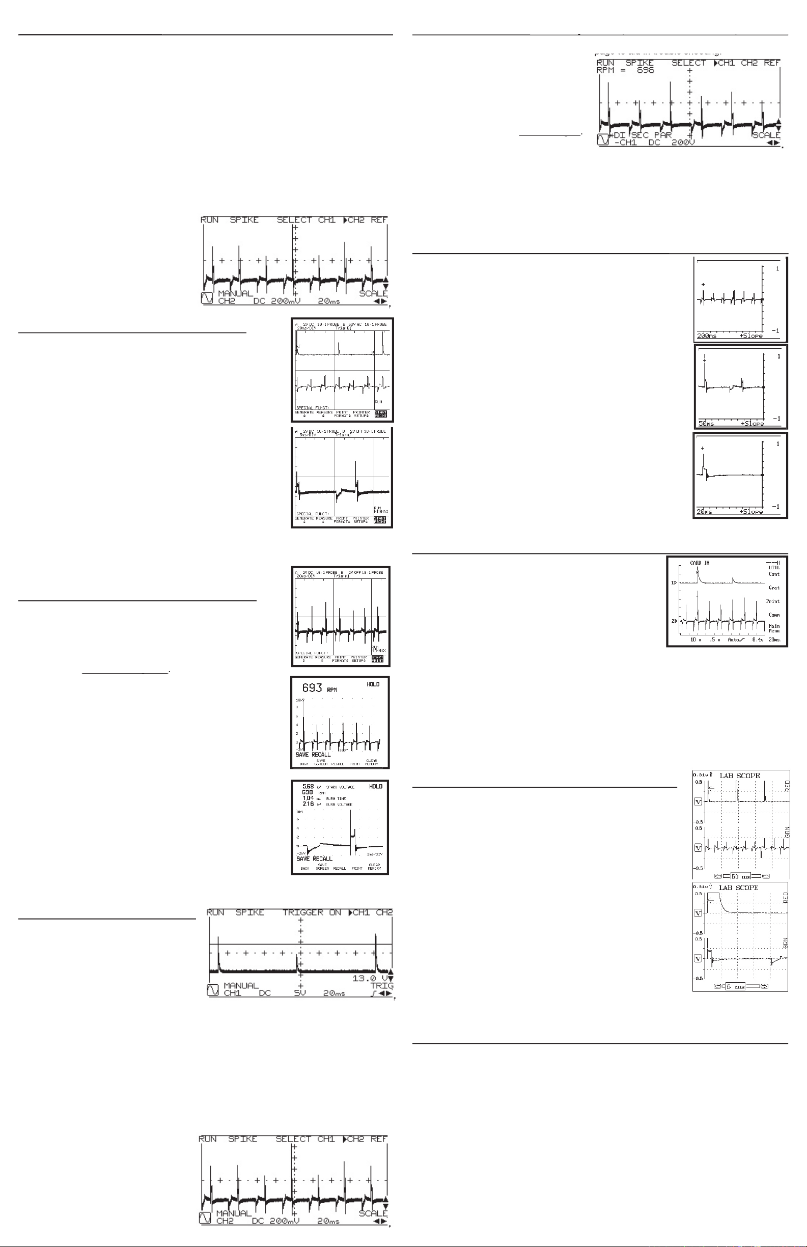
2. Connect the Ferret 951 or Fluke RPM80 to Input 2 of the 97,
trigger port on the 97, 97/Auto as well. Set Channel B to DC
3. Set the trigger level at about 8 volts with a positive slope.
4. Connect the KV Clips to each of the DIS sparkplug wires only.
The screens show what a 6 cylinder DIS engine looks like on the
waveform looks like when Channel B is turned off and the Min/Max feature is activated for
2. Connect the Fluke RPM90 to the trigger input on the Fluke 98
/ 98-2, and to Cylinder #1.
3. Use the Vehicle Data function on the Fluke 98 / 98-2 to select
the proper number of cylinders. Regardless of the ignition
type, select
4. Connect the KV Clips to each of the DIS sparkplug wires only.
function.
The screen above shows what a 6 cylinder DIS engine looks like
the features of the Fluke 98 / 98-2 to display and analyze the ignition waveform.
to Channel 1 input and then to Cylinder
2. Connect the Ferret 953 to Channel 2
Adapter.
3. Connect the Ground lead of the Ferret 953
to a good engine ground, and connect the KV Clips to each of the DIS sparkplug wires
4. Turn the scope on and confi gure Channel 1 to the following parameters: 5 volt range, DC
to negative. Plug a KV Lead into the Ferret 953. If the labscope display shows an inverted
fi ring peak, plug the KV Lead into the other bank of connectors. Continue until all KV leads
The screen below shows what a 6 cylinder
 Loading...