

OPERATOR’S MANUAL
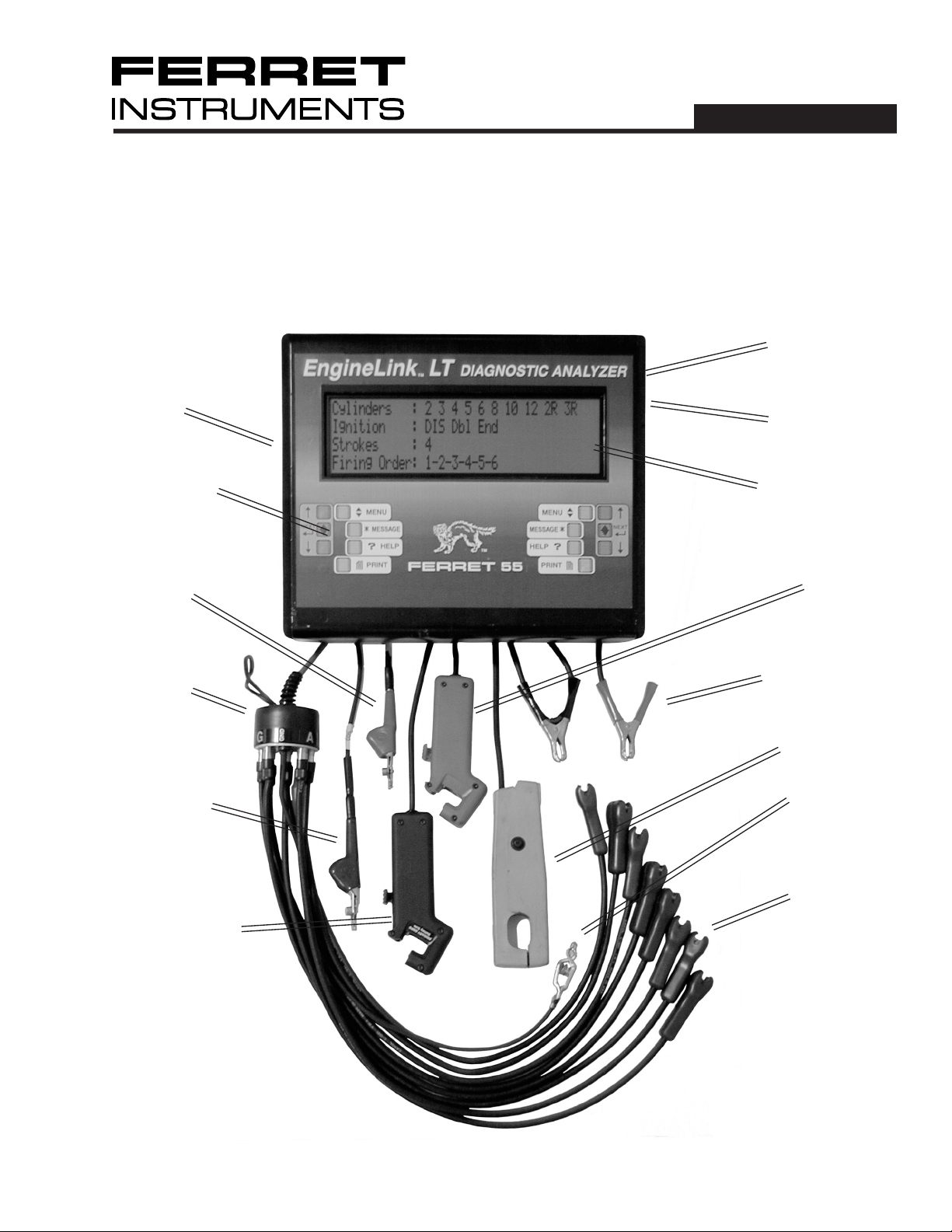
EngineLink™ LT
Diagnostic Analyzer
I/R Port
Control
Buttons
Auxiliary Volts
Leads
55
BNC 1 Sync
Output
BNC 2 PrimarySecondary Out-
put
Backlit Display
Spark Pickup
Spark Can
Coil Primary
Clip
Primary Amps
Probe
Power Leads
Amp Probe
Spark Can
Ground
KV Clips
© Copyright 2005, GxT, Inc., All Rights Reserved
1

Contents
Specifications ........................................................................................................................................3
Connecting to a DIS Car .......................................................................................................................4
Connecting to a Distributor Car ...........................................................................................................5
Connecting to a No Coil Minus ............................................................................................................6
Keys & Controls ..................................................................................................................................... 7
Initial Setup ............................................................................................................................................7
Ignition Menu ....................................................................................................................................8-13
Ignition Primary ................................................................................................................................8-9
Ignition Secondary .......................................................................................................................10-11
Hard Start ..........................................................................................................................................12
Troubleshooting DIS No-Start Cars ...................................................................................................12
Power Menu .....................................................................................................................................13-15
Electronic Compression ....................................................................................................................13
Power Contribution ............................................................................................................................ 14
Power Balance - Automatic/Manual .................................................................................................. 15
Electrical Menu ...............................................................................................................................16-17
Starting/Charging History .................................................................................................................. 16
Volt Amp Meter ..................................................................................................................................17
Auxiliary Meter ..................................................................................................................................18
Zero Amp Probe ................................................................................................................................17
Sensors Menu .................................................................................................................................17-19
TPS Test ............................................................................................................................................ 17
O2 Sensor Test ..................................................................................................................................17
Auxiliary Meter ..................................................................................................................................18
Logic Trace Scope ............................................................................................................................. 18
Solenoid Duty Cycle ..........................................................................................................................18
Injector Drive ..................................................................................................................................... 19
Fuel Menu
Injector Drive ..................................................................................................................................... 19
O2 Sensor Test ..................................................................................................................................17
Solenoid Duty Cycle ..........................................................................................................................18
Reports Menu..................................................................................................................................20-21
Run Auto-Test ...................................................................................................................................20
Print Saved Data ............................................................................................................................... 20
Visual Inspection ............................................................................................................................... 21
Auto-Test Configuration .....................................................................................................................20
Setup Menu .....................................................................................................................................21-23
Engine Setup.......................................................................................................................................7
EngineLink Setup .........................................................................................................................21-23
LCD Contrast .............................................................................................................................21
Custom Header .......................................................................................................................... 21
Save Setup ................................................................................................................................22
System Diagnostics ...................................................................................................................22
Scope Setup .............................................................................................................................. 22
Printing ................................................................................................................................................. 23
Demo Mode .......................................................................................................................................... 23
Typical Readings ............................................................................................................................24-25
Replacement Parts & Accessories ....................................................................................................26
Warranty & Service .............................................................................................................................. 27
Safety Warnings ...................................................................................................................................28
2

Introduction
The EngineLink™ is a professional grade tool for diagnosing automotive ignition, fuel injection, and
electrical systems. Test DIS and Distributor engines. Diagnose problems with ignition, starting/charging
and fuel-delivery systems, as well as computer sensors and drivers. Our AutoSort feature automatically
determines coil and plug polarity on DIS engines. The Autotest function performs Ignition Primary, Ignition
Secondary, Power Tests, Starting/Charging History, and Compression Tests automatically in about 10
minutes. Power Balance and Power Contribution checks cylinder performance on DIS and Distributor
engines. Primary Amps checks coils and modules. Spark Burn and KV tests check ignition plugs and
wires. Cranking Analysis checks cylinder compression uniformity and Starting/Charging Analysis tests
Specifications
Measurement Ranges
Battery Volts ........................................................................................................................ to 19.99 Volts
Volts, Aux (10 Meg) ................................................................................................................ ±20.00VDC
..................................................................................................................................... to 50.0 VAC Pk-Pk
Amps, Inductive ................................................................................................................0 to ±600 Amps
Tachometer ................................................................................................................... 100 to 5,000 RPM
Dwell, Ignition ......................................................................................................... Degrees, %, or mSec.
Driver/Points Resistance ...................................................................................................... 0 to 3.0 Volts
Dwell Variation ..........................................................................................................................in Degrees
Timing Variation ........................................................................................................................in Degrees
Ignition Coil Amps ..............................................................................................................0 to 19.9 mSec
Coil Amps Build Time ..........................................................................................................0 to 9.9 mSec
Spark Burn Time ..................................................................................................................0 to 9.9 mSec
Ignition Energy ....................................................................................................0 to 99 milliVolt-Seconds
Secondary KV ..................................................................................................................0 to 32 Kilovolts
Pulse Rate .......................................................................................................................... 0 to 999 Hertz
Cylinder Power Balance .......................................................................................................% RPM Drop
Cylinder Power Contribution ..................................................................................................Speed Index
Amps Ripple ................................................................................................................ Message Indicator
Cranking Compression ....................................................................................................... % Amps Peak
Injector Amps Drive Time ..................................................................................................0 to 99.9 mSec
Injector Peak Amps............................................................................................................0 to 19.9 Amps
Throttle Position Sensor ..................................................................................................... Glitch Catcher
O2 Sensor ................................................................................................................. Volts and Crossings
with Optional Sensors:
Diesel RPM ................................................................................................................... 100 to 5,000 RPM
3
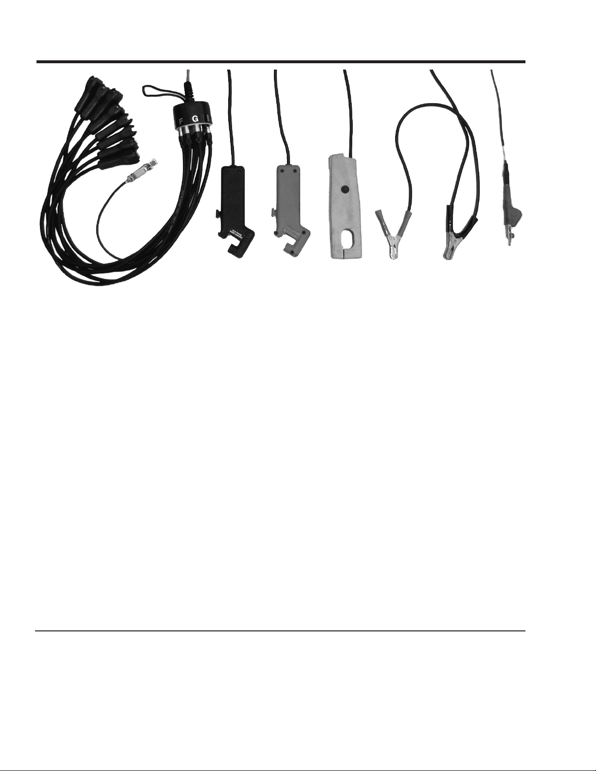
Connecting to a Distributorless Ignition
Sparkwire Clips
Primary Amps Pickup
Spark Pickup
Amp Probe
Power Leads
Auxiliary Lead
SPARKWIRE CLIPS
The EngineLink™ automatically sorts negative and positive firing plugs, and figures out coil pairings.
Connect the center Sparkwire Clip to #1 Cylinder, and connect the rest of the Sparkwire Clips to any
cylinder in any order. Connect the ground lead to a good engine ground.
PRIMARY AMPS PICKUP - DIS
Put the black Primary Amps Pickup around the wire that provides 12V power (B+) to the ignition module
and all coils. You may hookup around the wire anywhere in the wiring harness, but be sure the pickup is
around the wire that carries only the ignition pulses. The pickup label must face toward the battery plus
end of the wire (away from the coil).
SPARK PICKUP
The red Inductive Spark Pickup connects about the #1 cylinder plug wire. Connect close to the plug and
at least 4 inches away from the Sparkwire Clip on #1 cylinder. The label on the Pickup should face the
spark plug.
INDUCTIVE AMP PROBE
Connect the probe around the negative battery cable with the arrow pointing away from the battery, or the
positive battery cable with the arrow pointing towards the battery.
12V BATTERY LEAD
Connect the power leads to vehicles 12 volt battery. The connection must be made at the battery.
AUXILIARY LEAD
Not a required connection. Use the Auxiliary Lead for Sensor and voltage tests.
Primary Wire Colors
Manufacturer Wire Color
GM, Some 4 Cyl. Pink
GM, All Other Pink/Black
Chrysler Green/Black or Red
Chrysler Imports Black/White
Ford 4 Cyl. Blue
4
Otherwise, consult the car’s service manual wiring diagram.
Manufacturer Wire Color
Ford, All Others Red/Green
Hyundai Black.White
Infiniti Brown/Yellow
Lexus Black/Orange
Mazda Red/Lt. Green
Toyota Black/Orange
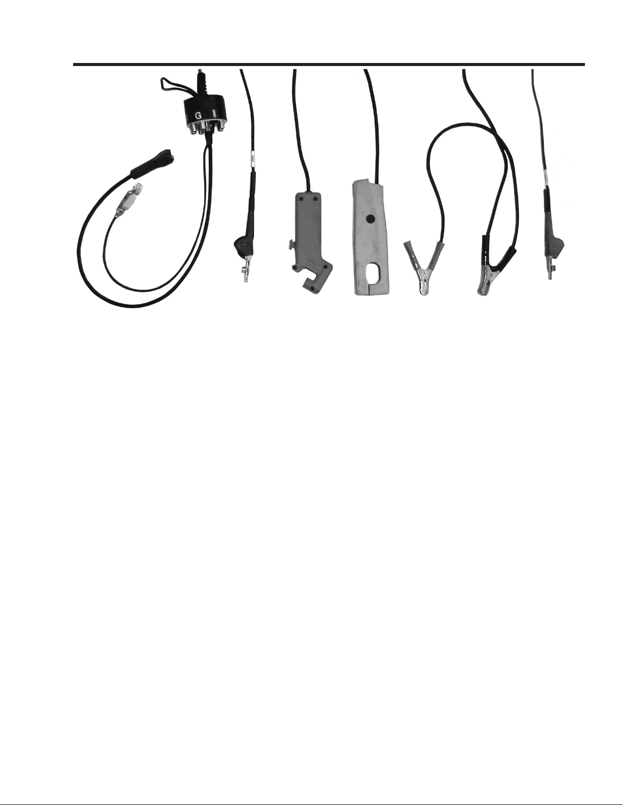
Connecting to a Distributor Ignition
Sparkwire Clip
Coil Primary Clip
Spark Pickup
Amp Probe
Power Leads
Auxiliary Lead
SPARKWIRE CLIPS
Disconnect all Sparkwire Clips from the Spark Can except the middle lead. Connect it to the coil wire. If
the ignition system uses an internal coil, use one of the provided KV Plates.
COIL PRIMARY CLIP
Connect to the ignition coil primary (-) terminal. Sometime labeled “TACH”, it is the signal source for the
ignition primary circuit measurements. It is necessary for ignition suppression.
SPARK PICKUP
The red Inductive Spark Pickup connects about the #1 cylinder plug wire. Connect close to the Distributor.
The label on the Pickup should face the spark plug.
INDUCTIVE AMP PROBE
Connect the probe around the negative battery cable with the arrow pointing away from the battery, or the
positive battery cable with the arrow pointing towards the battery.
12V BATTERY LEAD
Connect the power leads to vehicles 12 volt battery. The connection must be made at the battery.
AUXILIARY LEAD
Not a required connection. Use the Auxiliary Lead for Sensor and voltage tests.
KV PICKUP PLATES
Pickup plates are provided for GM, Toyota, and Nippondenso systems that have the coil located within the distributor.
To read KVs, clip the appropriate pickup plate to the distributor housing, attach a Sparkwire KV Clip to the bar or
post on the pickup plate, and plug it into either the Distributor KV Lead or the Cylinder #1 position of the DIS KV
Harness.
NOTE: The KV pickup plates are designed to be sensitive. To obtain valid readings, keep hands and wires away
from the KV Pickup Plate and the KV Clip during testing.
5
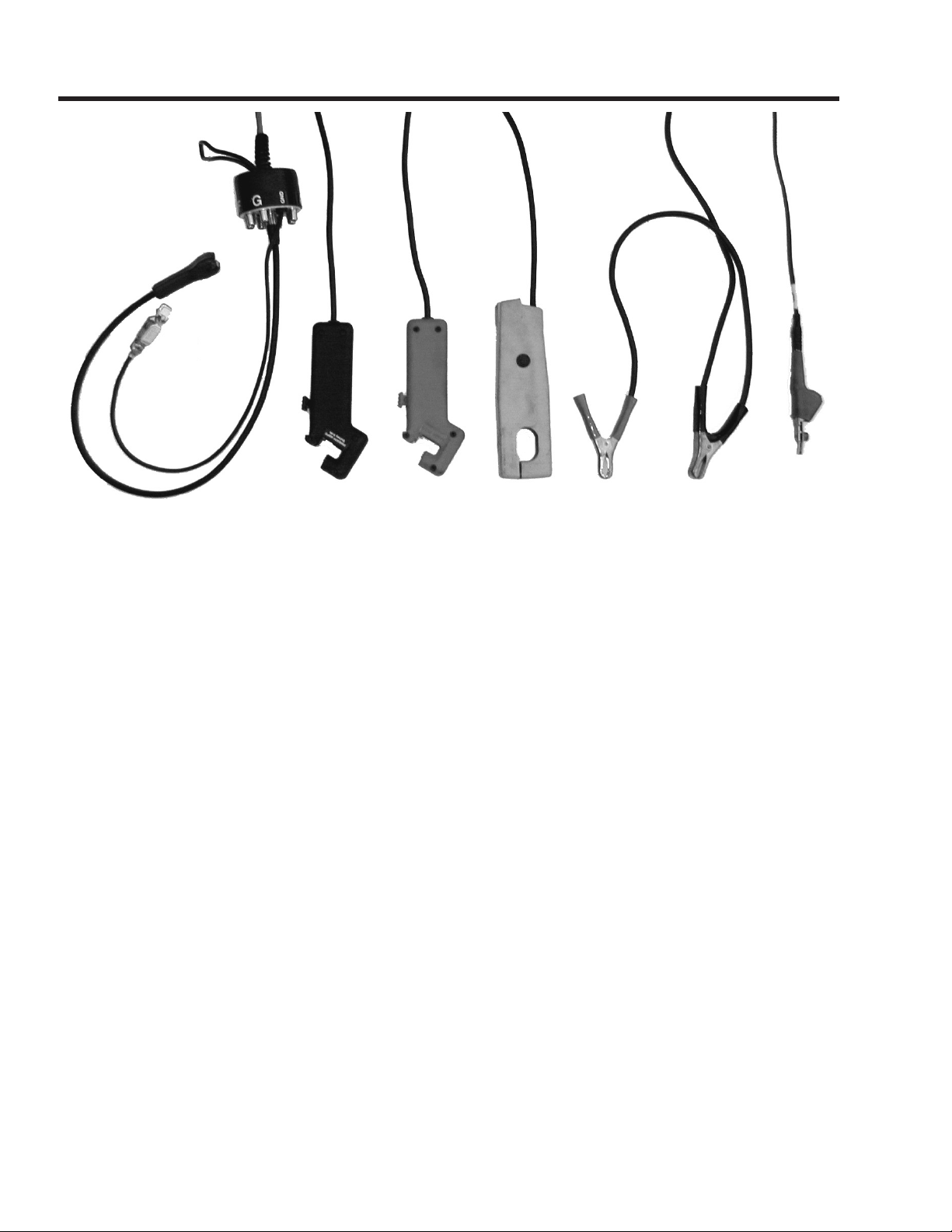
Connecting to a No Coil Minus Ignition
Sparkwire Clip
Auxiliary Lead
Coil Primary Clip
Spark Pickup
Amp Probe
Power Leads
SPARKWIRE CLIPS
Disconnect all Sparkwire Clips from the Spark Can except the middle lead. Connect it to the coil wire. If
the ignition system uses an internal coil, use one of the provided KV Plates.
PRIMARY AMPS PICKUP
Put the black Primary Amps Pickup around the wire that provides 12V power (B+) to the ignition module
and coil. You may hookup around the wire anywhere in the wiring harness, but be sure the pickup is
around the wire that carries only the ignition pulses. The pickup label must face toward the battery plus
end of the wire (away from the coil).
SPARK PICKUP
The red Inductive Spark Pickup connects about the #1 cylinder plug wire. Connect close to the distributor.
The label on the Pickup should face the spark plug.
INDUCTIVE AMP PROBE
Connect the probe around the negative battery cable with the arrow pointing away from the battery, or the
positive battery cable with the arrow pointing towards the battery.
12V BATTERY LEAD
Connect the power leads to vehicles 12 volt battery. The connection must be made at the battery.
AUXILIARY LEAD
Not a required connection. Use the Auxiliary Lead for Sensor and voltage tests.
A No Coil Minus ignition is an ignition system where the secondary ignition coil is housed in the Distributor
Cap, and the coil minus lead is not accessible. Some Toyota and Nipondenso ignitions are of this type.
6
MENU
IgnitionLink LT
ENGINE ANALYZER
HELP
PRINT
HELP
PRINT
MENU
MENU
Press the MENU key anytime you want access
to the main test menu.
MESSAGE
The MESSAGE key is active when the flashing
message symbol '* is on the screen. Messages
may span several screens. Press the MESSAGE
key until all messages have been viewed, and the
original screen has been restored.
HELP
Press the HELP key when you want context
sensitive help.
PRINT
Press PRINT to print the display contents to a printer.
Arrow Keys
Use the up and down arrow keys to change numbers or make a different selection.
Keys & Controls
NEXT
The NEXT key is used to go on to the next step in a test or procedure or to act on an item that is selected.
In some cases the NEXT key will clear minimums or maximums and restart a measurement.
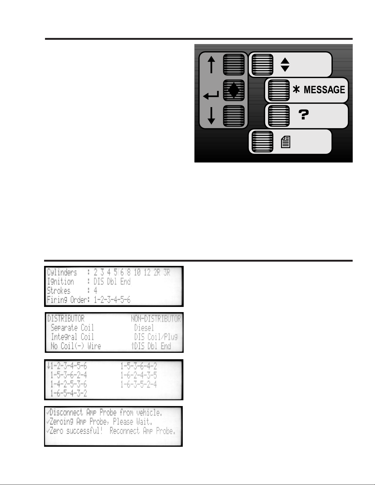
Initial Setup
The setup Engine Setup screen automatically appears
after power is applied to the unit. You must program the
EngineLink with the proper information about the vehicle
to be tested. Use the up and down arrows to move the
cursor to your selection. Pressing NEXT will enter the
selection and move to the next menu.
Select the number of cylinders, and press NEXT. A new
screen will appear, offering a choice of ignition type.
Distributor ignitions will have a Separate Coil or an
Integral Coil, where the coil is inside the distributor
housing (like GM HEI). In some cases, as with many
Nippondenso ignitions, the Coil (-) wire is not accessible.
In that case, SELECT No Coil (-) Wire.
Non-Distributor ignitions include Diesel engines, DIS
Coil/Plug, and DIS Dbl End (double end or output) where
each coil fires two plugs at the same time.
Select the ignition type, and press NEXT. Select 4 or
4, the results will be displayed in firing order sequence.
2 strokes, and select the firing order. Choosing a firing
order causes test data to be displayed in cylinder block
number sequence. If the default is accepted, e.g., 1 2 3
7
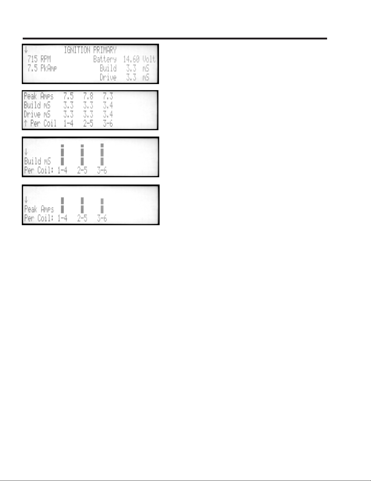
Ignition Primary - DIS
This test measures the input power and response of
the coil. If there are no readings, or they are obviously
wrong, check your connections.
COMPOSITE SCREEN
RPM is read by the black Primary Amps probe from the
current pulses drawn by the ignition coils. Battery voltage
comes from the red and black Battery Clips. The next
display line shows the average ignition primary amps
and the average milliSeconds it took for all coils to build
up the current during dwell.
DRIVE MILLISECONDS
The Drive MilliSeconds reading is the total dwell time
from the time the coil begins to charge to the time of
plug firing. In current-limiting electronic ignitions, the
difference between drive and build time is the “hold”
period.
MULTISPARK
Some ignition systems spark more than once during
each power stroke. If so, the words “Multispark Ign.” will
appear with the number of sparks per ignition.
INDIVIDUAL COIL READINGS
Press the up and down arrows to see individual coil readings. The numerical screen shows Peak Amps,
Build and Drive milliSeconds per coil. Two more screens show peak amps and build milliSeconds in bar
graph format.
PEAK AMPS
Look for equal current in each ignition coil, between 4 and 11 amps. If the primary ignition supply circuit
has bad connections, all amps may be low.
BUILD MILLISECONDS
These readings are useful for checking current-regulating ignitions that take a fixed time to build coil
current. Typical build time is 3 to 4 mSec. This time is nearly constant up to about 3000 RPM, and then
begins to shorten as RPM increases. If battery voltage is low, build times will lengthen.
Build time is a function of battery voltage, the inductance of the coil primary, and the peak amps level at which
the ignition module is set to regulate. The following relationships exist, if other factors are constant.
Long build time may be caused by high resistance in the primary circuit. Remember that the coil primary
circuit includes the power feed, the coil primary, the drive module, and its connection to ground. Increased
resistance from loose or corroded connections limits the primary current. This may cause lower peak amps
or longer build time readings.
Short build time may be caused by shorted coil windings.
Build time will be slightly longer while cranking, because of reduced battery voltage. If the ignition module
is not regulating at all, then Peak Amps can be High and Build can be Long. Both will be limited only by
the primary circuit resistance and battery voltage.
8

Ignition Primary - Distributor
PRIMARY
AMPS
BUILD
mSec
COIL
PEAK
AMPS
SPARK
LINE
PRIMARY
VOLTS
0 v
SPARK
BURN
TIME
IGNITION TIMING CYCLE
BUILD
(DWELL)
AMPS
HOLD
DWELL SECTION
BATTERY
VOLTAGE
IGNITION ENERGY
Ignition energy is the quality of the ignition coil inductance.
This indicates the coil “kick” in milliVoltSeconds (mVSec).
The engine must be cranking or running to produce a
readable signal. Typical standard ignition coils produce
25 to 40 mVSec. High energy ignitions have 40 to 60
mVSec. Readings below 20 mVS suggest that inadequate ignition energy is being delivered by the coil.
COIL OSCILLATIONS
This is an indicator of liveliness in the ignition coil. Shorts in coil insulation or in connected components
usually dampen the oscillations so they are reduced or eliminated. Points driven ignition coils usually
show 4 to 8 oscillations, which are more than electronic ignitions that do 1 to 4. Some Chrysler ignition
modules begin dwell immediately after the spark burn, so they normally do not show any oscillations.
DRIVER MODULE / POINTS VOLTAGE
“Driver” is the voltage during the dwell time. For mechanical points it should be less than 0.3 volts.
Electronic modules typically have 0.5 to 1.5 volts. Ignitions made alike should compare within 0.2 volts.
In this test, a higher voltage indicates a failing (high resistance) coil driver output transistor, bad points,
or a high resistance connection to ground.
DWELL
Press SELECT to display dwell in degrees, percent, or milliSeconds. MilliSeconds are useful for checking
the charging time for current-limited electronic ignitions, which take a fixed time to build up the coil amps.
A typical HEI coil charges in 3.5 mS at idle RPM, and 4.5 mS while cranking.
DWELL VARIATION
This is the difference in degrees between the longest and shortest dwell period. On electronic ignitions, it
could be from an unstable coil drive module. On points ignitions, mechanical sloppiness in the distributor
shaft bearings and cam shaft drive is the prime cause. At higher speeds, on points ignitions, the problem can
be floating contacts due to weak springs and poor lubrication. Readings should be less than 3 degrees.
TIMING VARIATION
Variations in timing is the difference in engine shaft degrees of the longest and the shortest times between
ignition firings. On pre-computer engines, variation meant looseness in the mechanical drive from the
crankshaft to the points cam. Sometimes timing is intentionally varied by engine computers.
Irregular idle RPM from O2 feedback fuel metering can cause timing variation also. Operating the engine at
higher RPM should reduce the variation to under 3 degrees. Read variation from 1000 to 3000 RPM with the
RPM held steady. During acceleration or deceleration, the Timing Variation is not a valid measurement.
Ignition Coil Primary Current and Voltage
9
 Loading...