


5-Gas Analyzer
16 & 16P Operator’s Manual
1

Table of Contents
Introduction .............................................................................. 4
Specifications ........................................................................... 3
Replacement Parts & Accessories .......................................... 3
Buttons & Controls ................................................................... 4
Connecting to the Vehicle ........................................................ 5
Start-up and Warm-up ............................................................. 6
Displaying Exhaust Measurements .......................................... 6
Analyzer Setup ......................................................................... 8
Display Contrast ............................................................... 8
Custom Header ................................................................ 9
Warm-Up Time ................................................................. 8
Engine Setup .......................................................................... 10
RPM Source ................................................................... 11
Fuel Type Selection ........................................................ 11
Report Printing ....................................................................... 12
Print a Report ................................................................. 12
Print Marked Results ...................................................... 12
Visual Inspection ............................................................ 12
Maintenance ........................................................................... 13
Zero ................................................................................ 13
Purge .............................................................................. 13
Calibrate ......................................................................... 14
Record & Playback ................................................................. 16
Printing ................................................................................... 15
Gas Theory ............................................................................. 17
Air Fuel Ratio .................................................................. 18
Catalytic Convertors ....................................................... 18
Hydrocarbons ................................................................. 18
Carbon Monoxide ........................................................... 19
Carbon Dioxide ............................................................... 19
Oxygen ........................................................................... 19
Oxides of Nitrogen ......................................................... 19
Routine Maintenance ............................................................. 20
Warranty & Service ................................................................. 21
Safety Precautions ................................................................. 22
© Copyright 2005, GxT, Inc., All Rights Reserved
2

Specifications
Measurement Ranges
Hydrocarbons (HC) ............................................0 to 15,000 ppm
Carbon Monoxide (CO) .............................................0 to 15.00%
Carbon Dioxide (CO2) ................................................0 to 20.0%
Oxygen ........................................................................0 to 25.0%
Nitric Oxide (NOx) ................................................0 to 5,000 ppm
Lambda ....................................................................... 0 to 10.00
AFR ................................................................................0 to 99.9
Tachometer ......................................................100 to 5,000 RPM
Warmup Time - Diagnostic Mode ................................. 3 Minutes
Warmup Time - Full Stability ....................................... 15 Minutes
Physical Dimensions
Operating Temp .............. 2° to 54°C .......................35° to 120° F
Storage Temp .............. -29° to 54°C .................... -20° to 130° F
Case Size .................... 28x33x9 cm ...................... 11x13x3.5 in.
Lead Length ...........................1.5 m ................................. 8 Feet
Weight ..................................4.5 kg .......................... 10 Pounds
Power Requirements ................................12 Volt Vehicle Battery
.................................................................... Optional A/C Adapter
Replacement Parts & Accessories
Exhaust Probe Flex Extension ..................................... H014-74
Upper & Lower Filter .................................................... H020-57
Calibration Gas ............................................................. H020-71
NOx Sensor .................................................................. M022-52
O2 Sensor ....................................................................M022-50
Extension Lead .............................................................W000-03
Power Lead ..................................................................W004-02
Cigarette Lighter Adapter .............................................W014-30
Temperature Probe .......................................................W022-21
Spark Pickup .................................................................X008-01
In-line Filter Element .................................................... H016-19
AC Power Adapter .........................................................X016-20
Thermal Printer ..............................................................V555-01
3

Introduction
The GasLink II™ is the ultimate in portable gas analyzers. Small
and portable, it can easily be taken on road tests and stored in a
toolbox.
Buttons & Controls
Next Button
Press this button to make a selection, or to access the main
menu.
Rec/Pause/Play Button
Press this button to activate the record and playback functions
of the analyzer. See the record section of the manual for more
information.
* Message
Whenever you see a flashing message signal, press the message
button to display the message. Messages are used to tell you when
zeroing is required or a fault is detected.
? Help
Press this button to display context sensitive help.
Print Button
Press this button to print what is on the screen.
4

Connecting to the Vehicle
Battery Power Leads
Connect the RED lead to the Battery
Positive, and the BLACK lead to
Battery Negative post. The analyzer
is protected in case you connect the
leads improperly.
Exhaust Sample Hose
Insert the sam ple hose into the
tailpipe. Be sure to route the sample
hose away from the exhaust flow.
The water separator should not be
vertical or horizontal, and should
not be directly in the exhaust flow.
When used during a road test, use
a hose clamp to secure the probe in
the tailpipe.
Spark Pickup
Clamp the RED spark pickup around
any sparkplug wire with the “Spark
Plug” label facing to w ards the
sparkplug. On systems where no
spark plug wires are available, the
pickup may be placed around the wire
feeding the coil primary.
5

Start-Up & Warm-Up
When power is applied to the unit, the start-up screen appears for
a few seconds. This screen shows the date of the last gas calibration and what fuel type and RPM input the analyzer is going to use.
The analyzer then proceeds automatically to the warm-up screen.
After a two minute warm-up and a thirty second zero, you are ready
to begin measuring gases. The analyzer defaults to the composite
screen. If the extended warm-up is selected, then analyzer has a
15 minute warm-up and a one minute zero.
To change the setup for the analyzer, press the NEXT Key.
Displaying Exhaust Measurements
Main Selection Menu
Use the SELECT buttons to move the selection arrow, then press
the NEXT button to make your selection.
Composite Screen
The composite screen displays all five gases, air fuel ration (AFR),
Lambda (l), and RPM. The screen also shows the status of the
memory used during the record functions. Press the NEXT button
to go to the main selection screen.
6

Big Digit Screen
Press either the Up or Down select buttons to alternate between
the composite, Grams per Mile and Big Digit screens. The big digit
screen displays the five gases and RPM in a large format. Press
the NEXT button to go to the main selection screen.
Grams Per Mile Screen
Press either the Up or Down select buttons to alternate between
the composite, Grams per Mile and Big Digit screens. The Grams
Per Mile Screen displays the estimated grams per mile of all gases.
This calculation is based on the miles per gallon constant that is
set using the Engine Setup function. Combustion Efficiency is also
calculated on this screen. It is displayed as CE. A number of .995
indicates the combustion efficiency is at 99.5% Use combustion
efficiency with lambda to see if there is an adequate fuel charge
and ignition in the combustion process. Press the NEXT button to
go to the main selection screen.
7
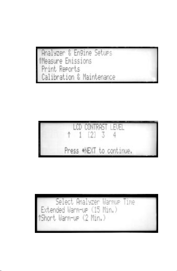
Analyzer Setups
Analyzer Setup Screen
Use the SELECT buttons to move the selection arrow to Analyzer
Setup then press the NEXT button. The following screen will appear
Use the SELECT button to select which analyzer setup you wish
to change, then press the NEXT button. Select EXIT to return to
the Setup Choices Screen.
Change the Contrast of the LCD
Use the SELECT buttons to move the select from one of 4 contrast levels. Press the NEXT button to return to the Engine Setup
Screen.
Change the Warm-up Time
Use the SELECT buttons to move the select a standard or extended
warm-up. The standard warm-up time is 2 minutes, while the extended warm-up time is 15 minutes.
8
 Loading...