

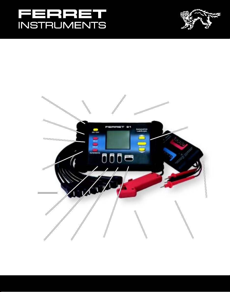
Automotive
TM
LabScope
AC Adapter
On/Off
Button
Help
Button
Hold
Button
Reference
Button
KV
Probes
Input (Optional)
RS232
Port
91
Channel 1,2,
and Common
Inputs
Select
Buttons
Labscope KV
Adapter
Channel 1
Volts/Div
Button
Channel 2
Volts/Div
Button
Trigger
Level
Button
Time/Div
Button
Trigger
Pickup
OPERATOR’S MANUAL
Test
Probes
1

Contents
Specifications.......................................................................................................... 3
Front Panel Controls ............................................................................................... 4
Understanding the Display ..................................................................................... 5
External Connections ............................................................................................. 5
Manual Setup........................................................................................................... 6
Standard Setups...................................................................................................... 7
Sensor Tests ............................................................................................................ 8
ABS Wheel Speed ................................................................................... 8
Oxygen Sensor 1 V.................................................................................. 8
Oxygen Sensor 5V .................................................................................. 8
O2 Sensor Dual 1 V ................................................................................. 8
Intake Air Temp IAT ................................................................................. 9
Engine Coolant ECT ............................................................................... 9
Fuel Temp Sensor ................................................................................... 9
Knock Sensor .......................................................................................... 9
Throttle Position ..................................................................................... 10
Throttle Position SW .............................................................................. 10
Magnetic (CKP/CMP) ............................................................................ 10
Hall Effect (CKP/CMP) ........................................................................... 10
Optical (CKP/CMP)................................................................................ 11
Dual Trace Hall Eff ................................................................................. 11
Magnetic CMP....................................................................................... 11
Magnetic VSS........................................................................................ 11
Hall Effect VSS ...................................................................................... 12
Optical VSS ........................................................................................... 12
Analog MAP Sensor .............................................................................. 12
Digital (Ford) MAP ................................................................................. 12
Analog MAF Hot Wire ............................................................................ 13
Analog MAF Vane Type.......................................................................... 13
Digital MAF............................................................................................ 13
EGR Valve Pos EVP ............................................................................. 13
EGR Pressure/Flow ............................................................................... 14
Actuator Tests ....................................................................................................... 14
Ignition Primary ..................................................................................... 14
Mult.Fuel Inj MFI ................................................................................... 14
Throt.Body Inj TBI ................................................................................. 15
PNP Fuel Injectors................................................................................. 15
Carb Mix Sol. MC................................................................................... 15
Bosch CIS Freq Valve ............................................................................ 15
EGR Ctrl Solenoid ................................................................................. 16
Idle Air Ctrl IAC ..................................................................................... 16
Transmission Shift ................................................................................. 16
Turbo Boost Ctrl..................................................................................... 16
Canister Purge Ctrl ................................................................................ 17
ABS Ctrl Solenoid .................................................................................. 17
EST - common, GM ............................................................................... 17
EST - Ford SPOUT................................................................................ 17
2

Contents
Secondary Ignition ................................................................................. 18
Communication Tests - Serial Data....................................................................... 18
Electrical Tests ...................................................................................................... 19
Apply Switch.......................................................................................... 19
Alt Field Ctrl ........................................................................................... 19
Battery B+ Supply V .............................................................................. 19
Battery Test Cranking ............................................................................. 19
V Drop High current ............................................................................... 20
V Drop Low Current ............................................................................... 20
Alt Output V Test .................................................................................... 20
Alt Diode Test ........................................................................................ 20
Audio Speaker Test ................................................................................ 21
12 V DC Switches .................................................................................. 21
Memory .............................................................................................................. 21
RS232 Communications ....................................................................................... 22
Technical Support ................................................................................................. 23
Replacement Parts ................................................................................................ 23
Specifications
Bandwidth 100 kHz
Channels 2
Voltage Ranges 0.5 V full scale to 100 V full scale
Vertical Position Fixed with Offset (ground moved to center screen)
Input Coupling AC, DC
Sample Rate 140 kS/s
Sweep Rate 60 s/Div to 100 µs/Div
Trigger Auto, Wait
Display 128 x 128 pixel LCD
Memory 2 test setups (waveforms, setups, and related information)
Presets At least 50 preset measurements with reference waveforms and
Help menu for each
Update Rate At least 3 times / Second
RS-232C Talk/Listen capability
Battery 6AA Alkaline cells, 20 hours operation (typical)
External Power With optional AC adapter
3

Front Panel Controls
ON/OFF To maximize battery life, the Ferret 91 includes an auto shut off feature. If
no buttons are pushed for approximately five minutes (20 minutes at a
setting of 60 sec/division), the Ferret 91 will turn off the LCD display and all
associated circuitry. To return to live operation, push any button.
SELECT Press the SELECT button to access the main menu, and to begin the
selection process for setup and measurement.
UP/DOWN Allows the user to scroll to a desired setup or measurement by moving the
highlighted line up or down in the on-screen menu.
CH1 Changes the voltage range of Channel 1. Pressing both the upper and
lower portions of the button simultaneously causes the ground reference
move to the center of the screen. Press both upper and lower portions
again and the ground reference will move to the bottom of the screen.
CH2 Same as CH1
TRIG Changes the voltage level of the trigger. Pressing both the upper and lower
portions of the button simultaneously causes the trigger slope to alternate
between positive and negative slope. The actual position of the trigger
start point is indicated by a “T” on the display.
TIME/DIV Pressing the TIME/DIV button sets the horizontal sweep speed for both
channels.
HELP Once a menu item has been selected, pressing the HELP button causes
information relating to that selected measurement item or menu feature to
be displayed on-screen. There may be multiple pages of information, which
can be scrolled through using the UP or DOWN arrow buttons. To exit the
HELP menu, press the HELP button again.
HOLD Pressing the HOLD button freezes the current on-screen waveform, and
brings up the waveform storage selection menu. The user can then decide
how to store the waveform and related information that is currently being
viewed.
REFERENCE Pressing the REFERENCE button displays a representative waveform for
the menu item currently selected. This waveform is only visible on-screen
while the REFERENCE button is being pressed. When in the Standard
scope mode, pressing the REFERENCE button will cause the current scope
parameters to be displayed.
Please Note: The reference waveforms included in the LabScope are
representative only, and may not exactly match the measurement the
instrument is currently making, or the waveform the labscope is currently
acquiring. Please use caution when comparing the signal actively being
4
acquired to the reference waveform.

Understanding the Display
Measurement Display Area
Channel 1
Voltage
Scale
Indicates
Trigger
Position
Indicates
AC Coupling
for Channel 1
Indicates
Channel 1
Filter in On
Trigger
Slope
W
Trigger
Level
_ _ _ _ _ _ _
_ _ _ _ _ _ _
Horizontal
Time/Division
Channel 2
Voltage
Scale
Waiting for
Trigger
Signal
Indicates AC
Coupling for
Channel 2
Indicates
Channel 2
Filter is On
External Connections
COM Signal ground connection. Common for CH1 and CH2.
CH1 Input for CH1 signal. AC coupled (DC Component of the signal is blocked).
Bandwidth using this input is 10Hz to 100kHz. With the input DC coupled
(direct coupled), the bandwidth is DC to 100kHz. Maximum input voltage is
300 VAC or 300 VDC. Please note the trigger source is always CH1.
CH2 Input for second signal in a dual-channel display mode. Maximum input voltage
is 300 VAC or 300 VDC.
RS-232 RS-232 interface for computer communication.
DC9V Input to power the unit from an external AC Adapter. (North America Only)
5
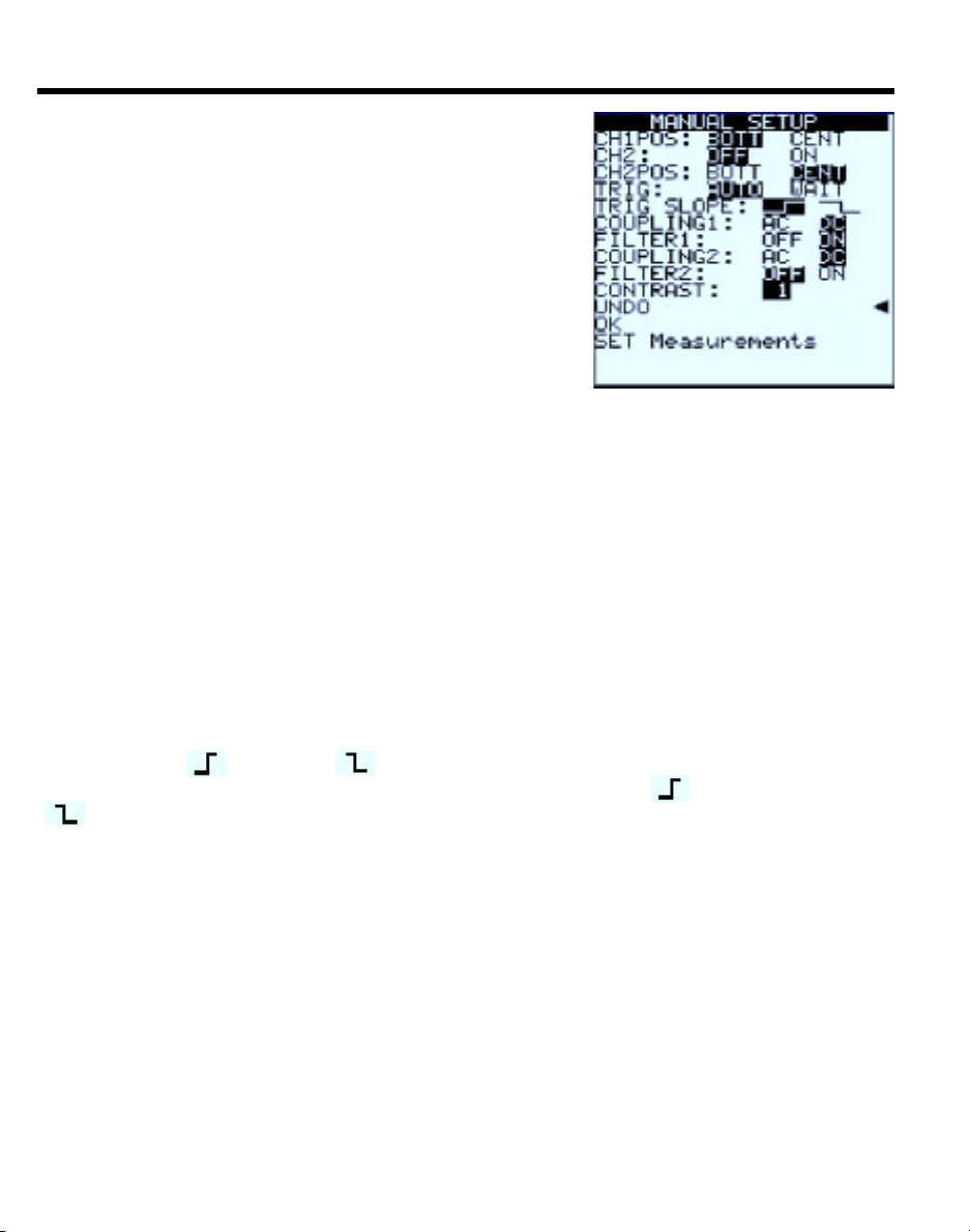
Manual Setup
Use the up/down arrow buttons to move the arrow to the
desired menu selection. The current selection for each
command is indicated by the reversed video. Press
SELECT to highlight the other function. Select OK to
begin operation.
CH1POS: BOTT CENT
The highlighted command positions the ground
reference on the bottom or center of the screen.
Pressing both the up and down segments of the CH1
key will perform the same operation.
CH2: OFF ON
Turns Channel 2 Off for single-channel operation or On for dual-channel operation.
CH2POS: BOTT CENT
Functions same as for Channel 1. Positions the ground reference at either the bottom
or center of the screen. Note: Setting both channels to the same position may cause
visual confusion if the signals are similar. Whenever possible, use bottom and center
for different channels.
TRIG: AUTO WAIT
Selects either Automatic trigger (trace runs continuously even without signal present)
and Wait (sometimes called Normal trigger). In WAIT, the scope waits for a signal
before starting the trace. (In this mode, a flashing “W” next to the “T” on the display
indicates that the LabScope is waiting for a trigger to begin the sweep. It is normal for
the display to be blank until a signal is present at the input.)
TRIG SLOPE:
Determines whether the scope triggers on the rising edge ( ) or the falling edge
) of the input signal. This is indicated on the display by the symbol at the bottom
(
left of the screen, to the left of the trigger level readout.
COUPLING1: AC DC
Allows the user to select between AC coupling or DC coupling for Channel 1. When in
AC-coupled mode, a small sinewave appears in the lower left corner of the display.
NOTE: AC coupling filters out the DC part of the incoming signal, and displays only the
AC signal changes. DC coupling displays the DC component of the signal along with
the AC signal changes.
FILTER1: OFF ON
When turned ON, a low-pass filter is connected in series with the input for Channel 1.
This limits the bandwidth of the scope, reducing background noise and interference on
the display. When FILTER1 is ON, an “F” appears in the lower left corner of the display.
NOTE: For faster signals, such as optical distributors, the decreased bandwidth with
the filter installed may alter the displayed signal. If unsure, always check the signal with
and without the filter turned on.
6

Manual Setup
COUPLING2: AC DC
Provides same functions for Channel 2 as described for Channel 1 COUPLING. When
in AC-coupled mode, a small sinewave appears in the lower right corner of the display.
FILTER2: OFF ON
Provides same function for Channel 2 as described for Channel 1 FILTER. When
FILTER2 is ON, and “F” appears in the lower right corner of the display.
CONTRAST:
Allows the display contrast to be adjusted through a range
of 0 (least contrast) through 10 (highest contrast).
UNDO
Cancels the current choices and returns the scope to the
previous setup. If UNDO is selected immediately upon
startup, the scope goes to the Standard Setup mode.
OK
Accept current Manual Setup choices and begin operation.
SET Measurements
Allows selection of up to two automated measurements
for display along with the acquired signal. The following
figure shows the Measurements submenu. NOTE: Menu
scrolls through measurements. Select up to two
measurements from the Measurements submenu using
the UP or DOWN arrow buttons and the SELECT button.
Accept your choices by selecting OK. The scope returns
to the Manual Setup menu where you can make further
setup changes or accept your previous choices.
Standard Setups
Standard Setup provides a quick way to begin actual lab scope operations, bypassing
the various setup menus. When Standard Setup is selected the LabScope is
automatically set to the following conditions.
CH1 15 V, DC Coupled
Trigger 3.3 V, positive Slope
Time/Div 10 ms
This setup displays most automotive signals, although
adjustment will usually be required for a stable, usable
display. In this mode, you can manually adjust the frontpanel controls and settings. If detailed adjustments are
required, the scope can often be configured more easily
in the Manual Setup mode.
7
 Loading...