

GWW ValueLine RO VALUE-5EZ50 Installation & Service Manual
Installation & Service Guide
GWW Inc.
1700 E Walnut Ave
Fullerton CA 92831
(714) 441-2893
(714) 441-0525 FAX
Please read this manual carefully before attempting installation.
Part #: VALUE-5EZ50
Introduction
Please read this entire service guide prior to
beginning installation.
The Valueline reverse osmosis drinking water system has been designed for quick and simple installation and
maintenance . By carefully reading this instruction manual and following the operational guidelines you will insure a
successful installation and reliable operation. Routine maintenance is essential to the longevity and performance of
the system. Filters should be changed every six to twelve months depending on the quality of the feed water supply.
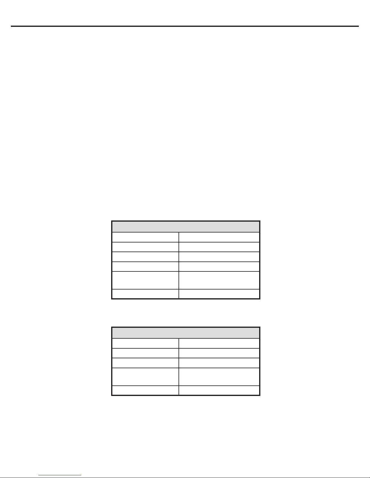
CONDITIONS FOR OPERATION
TFC - Thin Film Composite
Source Water Supply - TFC
Community / Private Non-Chlorinated
System Pressure 30-100 psi
Temperature 4º-38º C (40º-100º F)
pH Range 3.0-11.0
Maximum Supply
TDS Level
Turbidity <1.0 Net Turbidity (NTU)
2000 mg/L
Chemical Parameters - TFC
Hardness (CaCo3) < 350 mg/L (< 20 gpg)
Iron (Fe) < 0.1 mg/L
Manganese (Mn) < 0.05 mg/L
Hydrogen Sulde
(H2S)
Chlorine (C2) 0.00 mg/L
0.00 mg/L
CAUTION
D O N O T U S E TH I S S Y S T E M W H E RE TH E WAT E R I S M IC RO BI O L O GI CA LLY U NS AF E
O R O F UN KN OW N Q U AL IT Y. T H IS S YS TE M I S F OR US E O N P OTA BL E WATE R O NLY.
S O U RC E WAT ER E XC E E D IN G C HE MI C A L PA R AM ET ER S R E Q U I R ES P R E T RE AT ME NT.
Cold water
feed supply
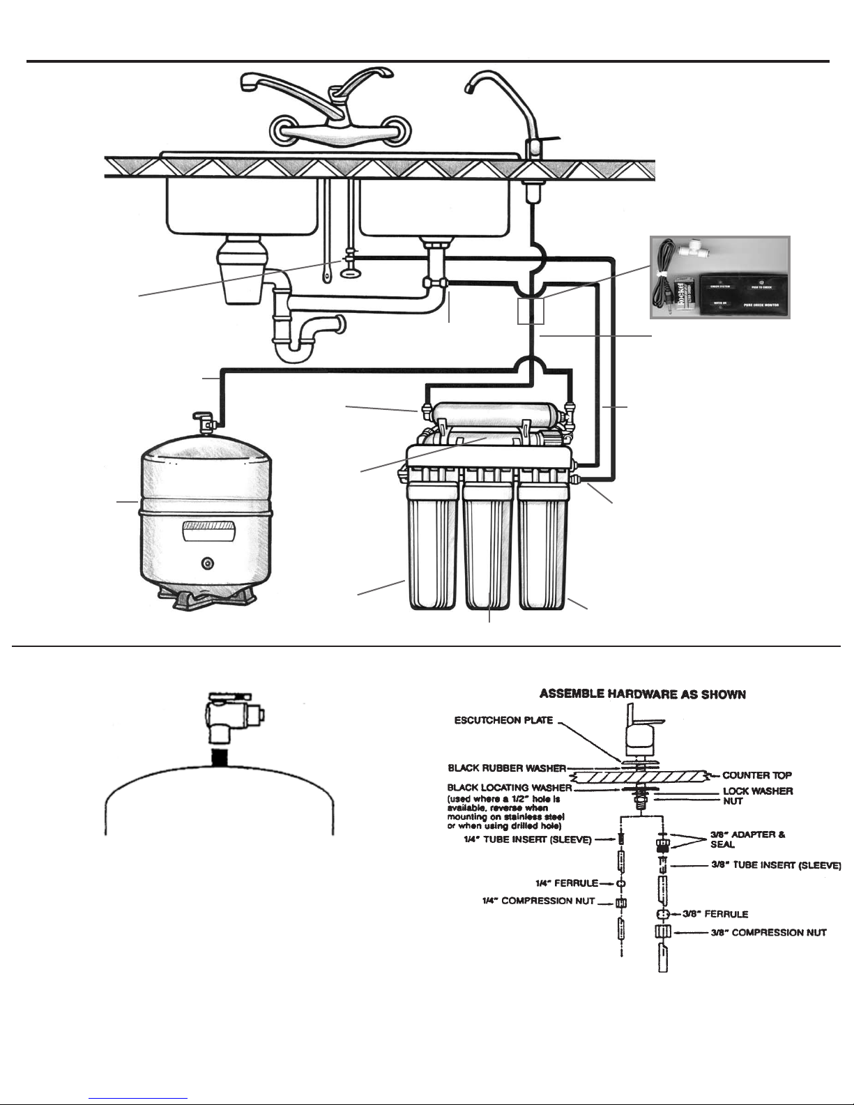
System and Faucet Diagrams
Long Reach
Drinking Faucet
TDS Monitor
Storage Tank
Mounting the Tank Ball Valve
1/4" Yellow
tubing to tank
Drain Connector
Stage 5: Carbon
Postlter
Stage 4: TFC
Membrane
Stage 3: Carbon
Block
Stage 2: Carbon Block
Non-Air Gap Faucet
1/4” Blue
tubing to faucet
1/4” Black tubing
from ow restrictor to
drain connector
1/4” Red
tubing from feed
Stage 1: Sediment
Prelter
Note: Do not tamper with the air valve on the storage
tank. It has been preset and screwed on with blue cap
by the manufacturers.
(1) Wrap the threads on the top of the water storage tank 3
times with plumbers (teon) tape only. Make sure it is tight,
but not over tight.
(2) Connect the tank ball valve assembly to the top of the
water storage tank.
(3) Connect the tube from the RO module to the water storage
tank.
 Loading...