


Operating manual
PR 1713/00
Operating manual 9499-050-42910 Release 1.x
Other Manuals for PR1713:
Installation manual 9499-053-43010 Release 1.0
System manual 9499-054-43110 Release 1.x
(general)
Batching manual 9499-057-43210 Release 1.x
Programming 9499-053-35410 Release 1.x
*:7 */2%$/ :HLJKLQJ 7HFKQRORJLHV *PE+ 32% ' +DPEXUJ *HUPDQ\
?

Please note
In correspndence concerning this product, please quote the type, name and release number
as well as all license numbers corresponding to the product.
This product is copyrighted in all its parts and m ay not be used or illegal modified or copied
without purchasing the license or written authority from the copyright owner.
Important
This product may be operated only by trained and qualified personnel. By using this product,
you agree to be bound by the terms of this notice.
Bitte beachten
Bei Schriftwechsel über dieses Produkt bitte Typ, Bezeichnung und Versionsnummer sowie
alle mit dem Produkt in Zusammenhang stehenden Lizenznummern angeben.
Dieses Produkt ist in allen seinen Teilen urheberrechtlich geschützt und darf ohne Erwerb der
Lizenz oder schriftliche Einwilligung nicht benutzt oder unerlaubt verändert oder kopiert
werden.
Wichtig
Die Bedienung des Produktes darf nur von geschultem, fach- und sachkundigem Personal
durchgeführt werden. Durch die Benutzung dieses Produktes werden oben genannte
Bestimmungen anerkannt.
V e u ille z n o te r, s.v.p.
Dans votre correspondance se rapportant au présent produit, veuillez toujours spécifier le
numéro de type, la description et le numéro de version ainsi que tous les num éros de licence
en rapport avec ce produit.
Les droits d´auteur de toutes les part ies de ce produit sont réser vés. Ce pr oduit ne doit êtr e ni
utilisé ni changé ni copié sans achat de la licence ou accord par écrit.
Important
L´exploitation de ce produit ne doit s´effectuer que par du personnel autorisé. L´utilisation du
produit implique la reconnaissance des conditions mentionnées ci-avant.
© GWT Global Weighing Technologies GmbH
Meiendorfer Str. 205, 22145 Hamburg
1998
All rights are strictly reserved.
Reproduction or divulgation in any form whatsoever is not permitted without written authority from
the copyright owner.
- Printed in Germany -

PR1713 Operating manual
Contents
CONTENTS
1 INTRODUCTION............................................................................4
ENERAL
1.1 G
1.1.1 Manual repartition...................................................................................................................4
1.1.2 Instrument description.............................................................................................................4
.......................................................................................................................................4
2 DESCRIPTION OF CONTROLS ..................................................6
ISPLAY
2.1 D
EYBOARD
2.2 K
PERATING CONCEPT
2.3 O
2.3.1 Operation via 'soft'-key............................................................................................................9
2.3.2 Selecting from selection boxes...............................................................................................10
2.3.3 Editing with alphanumeric characters ..................................................................................11
.........................................................................................................................................6
.....................................................................................................................................7
...................................................................................................................8
3 MAIN MENU..................................................................................13
OOT MENU
3.1 B
.................................................................................................................................13
4 FIXTARE ........................................................................................15
5 COUNTING SCALE......................................................................17
6 BATCHING.....................................................................................19
NPUT MENU FOR COMPONENT EDITING
6.1 I
6.1.1 Editing....................................................................................................................................20
6.1.2 Component parameters..........................................................................................................23
6.1.2.1 Batch Mode......................................................................................................................................................23
6.1.2.2 SPM output address.........................................................................................................................................27
6.1.2.3 SPM input address...........................................................................................................................................27
6.1.2.4 Preset Point......................................................................................................................................................27
6.1.2.5 Overshoot.........................................................................................................................................................27
6.1.2.6 + Tolerance, - Tolerance...................................................................................................................................27
6.1.2.7 Minimum Flowrate..........................................................................................................................................28
6.1.2.8 Calming time....................................................................................................................................................28
6.1.2.9 Restart mode....................................................................................................................................................29
6.1.3 Deleting..................................................................................................................................31
6.1.4 Printing..................................................................................................................................31
....................................................................................20
NPUT MENU FOR RECIPE EDITING
6.2 I
6.2.1 Editing....................................................................................................................................32
6.2.2 Recipe total mode...................................................................................................................35
6.2.3 Setpoint scaling......................................................................................................................36
6.2.4 Simulation..............................................................................................................................36
6.2.5 Deleting..................................................................................................................................37
6.2.6 Printing..................................................................................................................................37
.............................................................................................32
Page 1

Contents
PR1713 Operation manual
TARTING A BATCH PROCESS
6.3 S
6.3.1 Status display ........................................................................................................................ 38
6.3.2 Stopping the batch process ................................................................................................... 38
6.3.3 Continue, skip, abort............................................................................................................. 39
6.3.4 Messages during batching .................................................................................................... 39
ELECTING A REPORT
6.4 S
6.4.1 Consumption ......................................................................................................................... 40
6.4.2 Production report.................................................................................................................. 41
6.4.3 Last batch report................................................................................................................... 42
DDRESS LAYOUT OF SIGNALS
6.5 A
6.5.1 Digital in- and outputmodules PR1713/12. .......................................................................... 43
6.5.2 SPM-addresses for addressing the digital outputs............................................................... 45
................................................................................................................ 40
..................................................................................................... 38
.................................................................................................. 43
7 ANALOG TEST..............................................................................47
8 SETUP..............................................................................................49
9 WHAT CAN BE DONE IN CASE OF TROUBLE.....................51
RROR MESSAGES
9.1 E
9.1.1 Error messages on the weight display .................................................................................. 51
....................................................................................................................... 51
RROR MESSAGES ON THE TEXT DISPLAY
9.2 E
................................................................................ 52
10 INDEX............................................................................................53
Seite 2

PR1713 Operating manual
Operating concept
Page 3

Operating concept
1 I
NTRODUCTION
1.1 General
1.1.1 Manual repartition
PR1713 Operating manual
The operation for the normal PR1713 user is described
except ‘Setup’, which must be operated via direct keys or via the softkey menu.
Additional manuals:
• Installation, configuration and calibration are described in the ☞installation manual.
• Operating principle and behaviour of batching components, alarms and recipe are described in the
☞batching manual.
• Connection to PR1730, PR1740, PR1720 as a further weighing point and communication are
described in the ☞system manual.
• The commands of the programming language are described in the ☞programming manual.
in this manual
, comprising all functions
1.1.2 Instrument description
The PR1713 basic configuration is an
• gross, net or tare weight display
• taring
• fix tare tables
• zero setting
• weight ticket printing
• checkweighing
• remote display
• functions via digital inputs and outputs
indicator
with
As a
batching controller
• charge or discharge batching in net mode
• charge or discharge batching in gross mode
• charge or discharge batching without tare (top-up)
• discharge to set-point
• discharge complete
• manual component
• guide component for automatic set-point correction during runtime
• time components
• further control and synchronization components
• special components also programmable (licence PR1750/10)
• tolerance checking
• minimum material flow monitoring
• automatic overshoot correction
• preparation of consumption reports
• preparation of production reports
• preparation of batch reports
Seite 4
(licence PR1713/20 or PR1713/21), PR1713 also batches complex recipes.

PR1713 Operating manual
• remote display
• functions via digital inputs and outputs
Operating concept
As an additional
Due to
sting ones is easy.
Program package 'Filtering and controlling' (licence) can be used for controlling continuous weighing
processes.
• control and filter components in recipes
• own control applications
programmability
external weighing point,
(licence PR1750/10) writing individual applications or matching the exi-
a PR1720 can be connected to the DIOs card
Page 5

Operating concept
PR1713 Operating manual
2 D
ESCRIPTION OF CONTROLS
2.1 Display
Weight display status symbols
Standstill
Gross or net zero within 1/4d
G or B
T
Gross weight display, dependent of
national language
Tare weight display
NET
Net weight display
Batching is active
blinks, alarm is pending or manual
component
Seite 6

PR1713 Operating manual
2.2 Keyboard
Indicator controls
Operating concept
Display switch-over to gross mode,
as long as the key is pressed. Additionally, symbol B or G dependent
of selected language is displayed.
Display switch-over to tare weight,
as long as the key is pressed. Additionally, symbol T is displayed.
print-out-key for additional or selfprogrammed programs. Try to start
program 'Print'.
Menu control keys
Softkey for menu selection on the
alphanumeric display
Scroll key for selection from a list
Set and reset tare. The instantaneous
gross weight is stored in the tare
memory, provided that:
- weight standstill
- weight within the limits (0 ≤
weight ≤ f.s.d.)
- unit is not in error status.
Gross weight is set to zero. Condition is:
- weight standstill
- within zero set range
- not tared
- batching is not active
Quit-key for leaving an entry or menu and continuation at the next higher menu level.
More key for display of further menu items
Remaining keys
Cursor key for moving the cursor
during numeric text editing
Enter key for completing entries
Back-space key. When editing alphanumeric texts, the previous character is deleted.
Stop- key for stopping a running
batch process
Function keys for additional or selfprogrammed programs. Try to start
program 'F1'.
Alpha-numeric
keys
Page 7

Operating concept
PR1713 Operating manual
2.3 Operating concept
The PR1713 operation is menu-guided. For this purpose, the unit has a 'softkey'-functionality as with
PR1615. Below the display, there are three 'softkeys', which can be provided with 6-letter inscriptions
via the lower display line. The normal operation is very easy also without manual.
Keys for taring, untaring, zero setting, printing out, display of gross and net, three definable function
keys and a stop key are located below the softkeys.
15 keys for alphanumeric entry are located on the right side.
DEF
ABC
#"()=
3
2
1
GHI
4
PQRS
7
-+*/
.
JKL
5
TUV
8
ÄAE
0
→←
MNO
6
WXYZ
9
del
enter
Status
Stop
p
B T T
Weight display
Alpha-numer i c display 2*20
⇑ ⇑ ⇑
>0< P F1
in/out
morequit
F3F2
All functions shall be accessible for the user with as few keys as possible. Thereby, selecting flexible
menus and submenus, finding an entry from a list and entry of alphanumeric texts must be possible.
three
The
modes of entry/selection for the different requirements are
•
Menu selection with three softkeys:
, and .
Inscription text fields separated by small
triangles are displayed:
'clear
• Selecting an entry from a list by
'scrolling'
The actually selected function is displayed
with two arrows.
show print'
'!Recipe-7!'
• Editing with individual letters
A cursor is displayed:
'Material-123_ '
Seite 8

PR1713 Operating manual
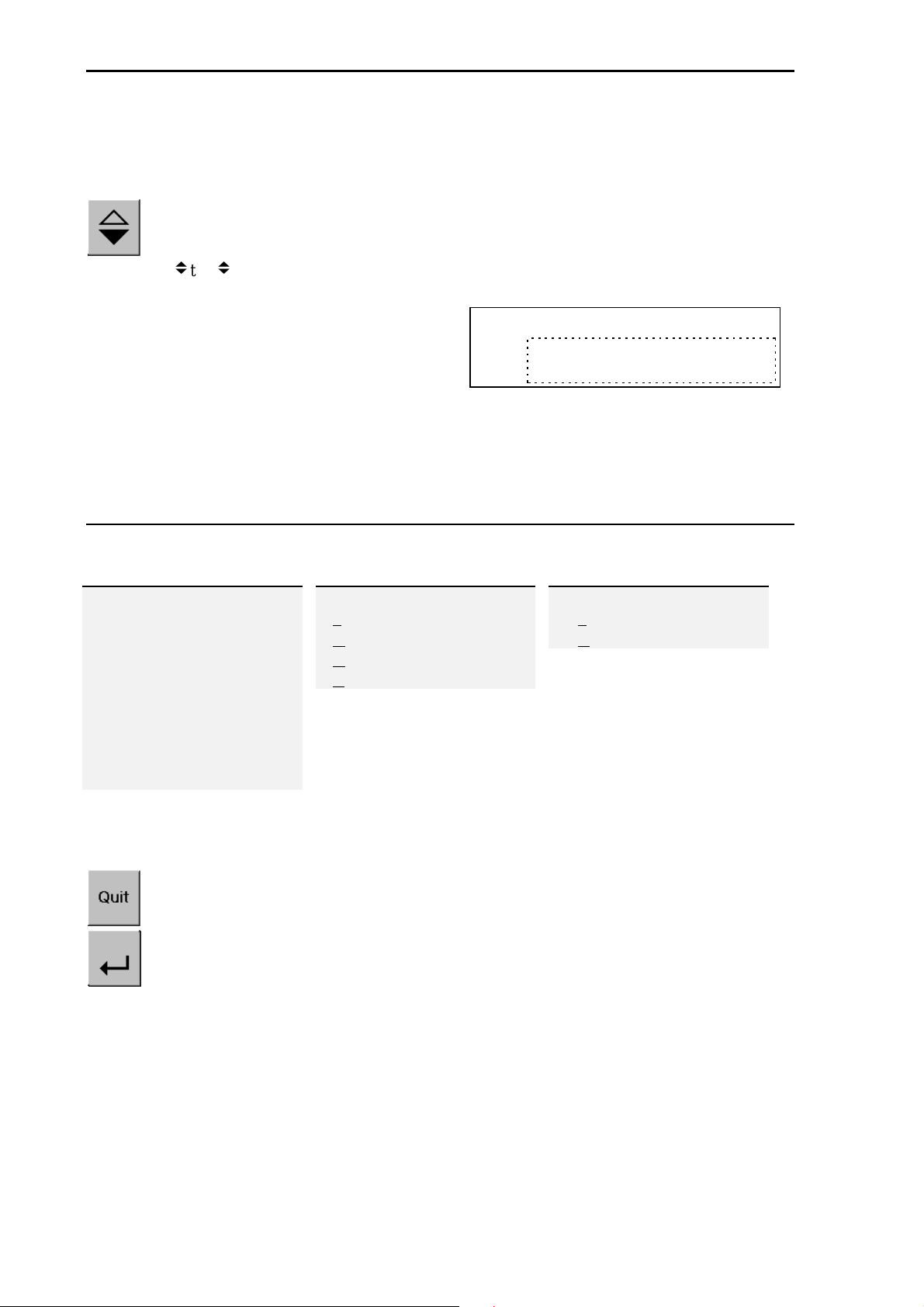
2.3.1 Operation via 'soft'-key
Each menu has a list of functions, which can be selected via softkeys.
Three functions are displayed at a time. Selecting a
function via 'softkeys' is displayed by two small triangles between
the inscription text fields ( ).
If more than three functions can be selected, double tri-
angles are displayed.
Display of the next three selectable functions is by pres-
sing key 'more'.
Operating concept
A menu item can be left with 'quit'. The operation is continued at the next higher level.
Page 9
Operating concept
PR1713 Operating manual
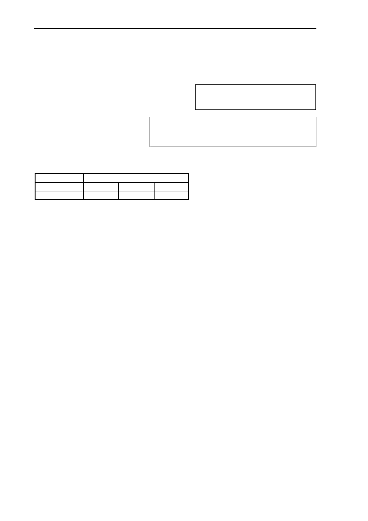
2.3.2 Selecting from selection boxes
An entry in a variable list can be selected by scrolling. If necessary, this list can be limited
by preselection (e.g. all names starting with 'A').
In the display, this type of selection is shown by two special characters left and right from
the selected !text!. Consequently, the overall list can be scrolled.
As scrolling would require pressing too many keys
with very long lists, the list entry can be entered
directly with the alphanumeric keys. Thereby, only
as many letters of the list entry as required for
identifying it clearly is need being entered, or until
the number of possible remaining selections is sufficiently low. By entry of alphanumeric characters,
selection from the list is limited and marked by display of a cursor. The cursor position marks the
length of list limitation. However, the overall list entry is always displayed. 'delete' is used to delete
the last character of limitation, until all list entries are selectable again.
Name of List
!List entry !
Example:
Overall list
*new* *new* *new*
A
AB
ABC
B
BA
BABX300
BBCT700
C
DEF
If the list contains apparent entry '* new *', a new entry can be inserted in the list.
without
A menu item can be left with 'quit'. Operation is continued at the next higher level.
Select the entry with 'enter'.
limiting Limitation by pressing key 'B'
_
B
A
B
ABX300
B
CT700
B
further
key 'A'
_
BA
BX300
BA
limitation by pressing
Seite 10

PR1713 Operating manual
Operating concept
2.3.3 Editing with alphanumeric characters
In the alphanumeric entry mode, a cursor blinks in the entry field. Unless already active, this mode is
accessible by pressing a key from the right keypad of PR1713. Then, the softkeys are without importance.
The arrow keys from the right keypad are used to shift the cursor. Entries and deletings act in
the cursor position.
An alphanumeric key has more than one
significations. After pressing for the first
time, the relevant first signification, e.g.
'A' is displayed in the cursor position. After pressing for the second time, e.g. 'B' instead of 'A' is
displayed; 'C' is displayed after pressing for the third time, etc. After the last signification, the first
one is displayed again. The entry of a character is completed by pressing another character key, or the
arrow keys. The character is removed by pressing key 'del'.
Parameter name
name field…
If only numeric values are required for an entry,
letters are not selectable via the editor. Therefore,
values such as 555 can be entered only by pressing
the key successively three times and without using
the arrow key. A decimal point can be entered with
the comma key. If a value has a polarity sign, a polarity sign can be entered by pressing the comma key
in the extreme left position.
With weight values, the unit can be scrolled using
the 'more' key. (g, kg, t, lb)
The single character editor can edit a longer character field than the space available for the editor. In
this case, the display field is shifted right and left. In
the last position, the partial character display is represented by special character '…'.
The 'backspace' key deletes the character before the cursor.
An entry can be completed with 'enter'. The changes are stored. The operation is continued at the next higher level..
The multiple key significations are:
# " ( ) = $ ? ! % 1
A B C a b c 2
D E F d e f 3
G H I g h i 4
J K L j k l 5
M N O m n o 6
P Q R S p q r s 7
T U V t u v 8
W X Y Z w x y z 9
. - + * /
(special characters dependent of
country) 0
The old value from before the change is displayed with 'quit'. By pressing 'quit', the operation is continued at the next higher level.
Page 11

Operating concept
PR1713 Operating manual
Seite 12

PR1713 Operating manual
Main menu
3 M
When the unit is ready for operation and batching is not active, the main menu functions are accessible.. Dependent of licence or programming, further or other application programs can be selected.
AIN MENU
FixtarCount Prod
Menu items at the uppermost menu level:
Softkey Function
Fixtar P Indicator functions with fixed tare value
Count P Counting application
Prod P Batch functions
Atest P Start test mode of internal weighingpoint
xxx P Other customer applications are appended to the list in this position
Setup Configuration, Calibration
The sub-menus with identification (P) are programmed in IEC1131 and can be changed freely with a
programming option by the user.
This uppermost main menu level is fixed in the firmware.
3.1 Boot menu
After switching on the mains voltage, the PR1713 version number is shown on the alphanumeric display. The main menu is active only thereafter.
Page 13

Operating concept
PR1713 Operating manual
Seite 14

PR1713 Operating manual
Fixtare
4 F
The fixed tare function permits taring of the scale with predefined tare values. These can be defined
by the user and are stored in a separate table in the database.
IXTARE
Fixtare Hopper1
! 1!
is displayed by selecting softkey 'Fixtar' from the main menu.
By scrolling
by pressing the numeric keys. In addition to its number, each entry has its plain text name. The fixed
tare number is selected with 'enter'.
With the fixed tare value selected, the weight display can be
tared with a fixed tare value, the fixed tare value can be edited, the current gross weight can be loaded and printed out in
the fixed tare memory.
2,5 kg
!!, the fixed tare value can be selected, or the fixed tare number can be selected directly
Fixtare hopper1
Tare
Edit
Weight
Fixtare hopper1
Print
Pressing softkey 'tare' tares the scale with the fixtare value. The display returns to the main menu.
Softkey 'edit' can be used for editing the plain text name and entering the fixed tare weight di-
rectly. The display returns to the selection menu.
Pressing softkey 'weight' stores the current gross weight in the fixed tare memory. In the printout
the value is put in <parentheses>. The display returns to the selection menu.
Pressing softkey 'print' prints out one or all fixed tare
values. The display returns to the selection menu.
• An entry can be completed with 'enter'. The changes are stored.
• The entry is left with 'quit'. When editing a value, the old value is restored. With an unchanged
value, a jump back to fixed tare selection is made.
Print
Single
All
Page 15

Operating concept
PR1713 Operating manual
Seite 16

PR1713 Operating manual
Counting scale
5 C
A counting scale permits conversion of a weight from the weighing point into a number via a factor.
These factors can be defined by the user and are stored in a separate table in the database.
OUNTING SCALE
Count Screws4
!
!
!
!
1
264 pcs
is displayed by selecting softkey 'Count' from the main menu.
By scrolling !, the fixed tare value can be selected, or the factor number is selected directly by the
numeric keys. Apart from its number, each entry has a plain text name. The count is updated continuously. The count factor is selected with 'Enter' .
The properties of the selected factor can be changed, displayed or printed out.
By pressing softkey 'set' , a new factor is calibrated.
1) Discharge the hopper: empty bin or plattform and set to zero or tare,
2) Calibrate with a selected number of objects and enter this value. Thereby, the accuracy is the
higher the higher the calibration weight, similar to every calibration.
The display returns to the selection menu.
Softkey 'show' displays the calibration values. The display returns to the selection menu.
Softkey 'print' prints out one or all count factors. The dis-
play returns to the selection menu.
Count Screws4
Set
Show
Print
Print
Single
All
• An entry can be completed with 'enter'. The changes are stored.
• Pressing 'quit' leaves the entry. When editing a value, the old value is restored. With an unchanged
value, the old value is restored. With an unchanged value, a jump back to the fixed tare selection is
made.
Page 17

Operating concept
PR1713 Operating manual
Seite 18

PR1713 Operating manual
Batching
6 B
All batching functions are classified in this menu item.
Report
Comp
During normal operation, only functions Batch start and Report are required.
In rare cases, the component and recipe tables are edited, usually by another person.
Key 'more' switches between the two 'softkey' menus.
Softkey Explanation
Report Selects a report
Batch Starts a batch process
Comp Edits components
Recipe Edits recipes
ATCHING
Recipe
Batch
Page 19

Batching
Quit
Quit
abc
Parameter value
remains unchanged
abc
changed parameter v alue
is accepted
With 'yes' all changes for this component
are accepted;
with 'no' they remain unchanged.
The component name is selected from a list by scrolling.
The list is shortend by entering the the first characters of the name.
PR1713 Operating manual
6.1 Input menu for component editing
Selecting softkey 'Comp' from the main menu displays:
Component Table
Delete
6.1.1 Editing
Edit
Print
Editing single components is done with
Survey
at the example of editing function
Select
com ponent nam e
Select param eter
select component
Name
Ø
Ø
Name
Preset
Ø
Ø
'edit'
:
×
×
store?
yes no
100 kg
×
×
Edit param eter
value
← →
Name
Preset 12
Seite 20
5 kg

PR1713 Operating manual
Batching
The entry is selected by scrolling !. A limitation of the list is
possible. In position '* new *', a new component can be
inserted. 'Enter' completes the selection.
Select Component
!
Sugar
!
Select Component
!
* new *
When trying to give a name to a component which was already assigned to another component, an error message is displayed.
• Pressing key 'quit' leaves the entry of a new component.
A number of specific parameters which shall be read out and changed as simply and quickly as possible. The parameter set changes dependent of the batch mode.
Component name + ...
A1, 2 B1 - B6
G1 - G6
WP Weighing point
DosMode Batch mode
SPM in SPM address
SPM out SPM address
Preset Preset point
OVRShoot Overshoot
Tol+ Max. tolerance
Tol- Min. tolerance
Minflow Min. flow rate
Calmtime Calming time
RST Mode Restart mode
Analo+ Max. analog value
Analo- Min. analog value
Name already exist
Batch mode
B8 D1, 2 D3 - D8
OK
RL, RQ, RW
!
Page 21

Batching
PR1713 Operating manual
The selected name is displayed in the uppermost line. In the
bottom line, all parameters can be selected. The first parameter is displayed. The relevant value is displayed beside the
parameter, i.e. a quick survey of all settings of a component is
possible by parameter scrolling.
For editing parameter 'Preset', selection with 'enter' is required. The value of this parameter is edited by entry of a number. See cursor in the numeric value. The unit is changed by
the 'more'-key.
Sugar
Preset: _15
Alle standard batch modes could be selected by scrolling.
Additional new mode names could be selected by entering
alphanumerical keys.
kg
Sugar
WP
!
!
Sugar
BMode
!
!
Sugar
SPM in
!
!
Sugar
SPM out
!
!
Sugar
Preset
!
!
Sugar
OVRshoot
!
!
Sugar
Tol.+
!
!
Sugar
Tol.-
!
!
A
!
!
B1
!
!
1
!
!
1
!
!
2 kg
!
!
5 kg
!
!
1 kg
!
!
1 kg
!
!
Sugar
The setpoint of the 'calming time' is a time, which has to be
entered with the units 'ms', 's', 'm' or 'h'. Eg. 1m30s are one
minute and thirty seconds.
MinFlow
!
!
Sugar
Calmtime
!
!
25 kg
!
!
1s
!
!
Sugar
RST Mode
!
!
!
!
0
Store ?
yes
• An entry can be completed with 'enter'. The changes are not stored.
• The entry is left with 'quit'. When editing a value, the old value is restored. With an unchanged
value, a jump back to parameter selection is made. When leaving the parameter entries, a prompt if
these data shall be stored is displayed. Subsequently, the operation is continued at the next higher
level with component name selection.
no
Seite 22

PR1713 Operating manual
Batching
6.1.2 Component parameters
6.1.2.1 Batch Mode
Each component can be a process step in a recipe. Determine the process step with the batch mode
during component definition, e.g. "Bx" for real components and "Dx" for dummy components. If a
guide component "Gx" was selected, the set-points of the following components are displayed as
calculated from the recipe during a production. The actual set-points referred to the guiding value are
output in the reports.
Batchable components B1-B6, G1-G6, B8
Manual components D1, D2
Dummy components D3-D8, RW RL, RQ
Analog components A1, A2
Other batch modes
6.1.2.1.1 Batchable components
Batchable components:
into/from silos is possible.
Net batching
Batch mode
nent for charge batching. Dossing is preceded by a tare step, i.e. the net weight is zero
when starting the batch. The recipe set-point
for this component is the net weight.
Charge batching
Batch mode B2 is used for charge batching.
Batching is not preceded by a tare step, i.e.
the last net weight remains unchanged. The
recipe set-point for this component is the net
weight based on the previous tare
Gross batching
Batch mode
to an absolute value. Before batching, the
tare is set to zero. The net weight is equal to
the gross weight. The recipe set-point for
this component is the gross weight.
is the normal batch compo-
B1
is used for charge batching
B3
All components for which automatic coarse + fine batching by weighing
Setpoint calculation:
setpoint = tara + setpoint
coarse_switch_off = setpoint - preset - overshoot
fine_switch_off = setpoint - overshoot
Setpoint calculation:
setpoint = old_tara + setpoint
coarse_switch_off = setpoint - preset - overshoot
fine_switch_off = setpoint - overshoot
Setpoint calculation:
setpoint = setpoint
coarse_switch_off = setpoint - preset - overshoot
fine_switch_off = setpoint - overshoot
Page 23

Batching
Discharge batching
Batch mode
nent for discharge batching according to B1.
Batching is preceded by taring, i.e. the net
weight is zero at batch start. The recipe setpoint for this component is the net weight.
Charge/discharge batching
Batch mode
ching according B2. Batching is not preceded by taring, i.e. the last net weight remains
unchanged. The recipe set-point for this
component is the net weight.
Gross discharge batching
Batch mode
ching to an absolute value. Before dosing,
the tare is set to zero. The net weight is equal
to the gross weight. The input value for this
component is the gross weight.
is the normal batch compo-
B4
is used for discharge bat-
B5
is used for discharge bat-
B6
PR1713 Operating manual
Setpoint calculation:
setpoint = tara - setpoint
coarse_switch_off = setpoint + preset + overshoot
fine_switch_off = setpoint + overshoot
Setpoint calculation:
setpoint = old_tara - setpoint
coarse_switch_off = setpoint + preset + overshoot
fine_switch_off = setpoint + overshoot
Setpoint calculation:
setpoint = setpoint
coarse_switch_off = setpoint + preset + overshoot
fine_switch_off = setpoint + overshoot
discharge component
The discharge mode B8 is used for total discharge. Before batching, the
tare is set to zero. The net weight is equal to the gross weight. The recipe set-point for this component is a gross weight. As discharging to
setpoint calculation:
setpoint = rest_value
ideal zero is rarely possible, batching is done at least until reaching rest value. Subsequently, the system waits until the calming time has elapsed, to discharge all rests, if possible. There is no fine flow.
6.1.2.1.2 Manual components
A manual component
For this, their input SPM_IN must be defined. Output SPM_OUT requests the user to start filling in
material. Batching is preceded by taring, i.e. the net weight is zero when starting the batch. The input
value for this component is the net
A manual component
weighed manual additions which are too small for being measured exactly by this weighing point.
Therefore, the set-point instead of the actual value measured after the calming time is recorded in the
batch report.
setpoint calculation:
setpoint = tare + setpoint
is batched manually by a user. It is acknowledged by a signal or a switch.
D1
.
behaves almost exactly like D1. However, the component is used for pre-
D2
Seite 24

PR1713 Operating manual
Batching
6.1.2.1.3 Dummy components
Dummy components
via SPM and PLC, e.g. timer, switch on/off, temperature control, motors. The SPM addresses for input and output are used in the
: non-batchable recipe entries, which control defined actions in the installation
function block
D3
D4
D5
D6
D7
D8
The
The time is entered with a resolution of 1 sec.
The
SPM_IN is omitted ! Restart by the control signal 'restart'
The SPM
status TRUE of SPM input address SPM_IN.
The SPM
The SPM
The SPM
SPM_OUT to FALSE.
component waits until the specified time has elapsed.
timer
component is used for making a pause of unpredictable duration. Waiting for
stop
waiting
set
delete
acknowledge
component sets output address SPM_OUT to status TRUE and waits for
component sets output SPM_OUT to TRUE.
component sets output SPM_OUT to FALSE.
component waits for status TRUE of input SPM_IN and sets output
setpoint = time_in_ms
6.1.2.1.4 RW, RQ, RL
RW (Wait), RL (Release), RQ (Request) are used in the recipe for production line synchronization.
Assuming a weighing point WX 'shared resource' for several production lines
RW
If WX shall not be started at recipe start, an RW component (wait component) must be used
as a first process step for WX in the recipe. The following recipe lines of WX are not handled
until started from another point in the recipe (RQ-component).
RQ
RL
The SPM input/output addresses of RW/RQ/RL can be used for synchronization, for process interlokking of for general status display.
The RQ component (request component) requests a weighing point WX and makes an attempt
to start the process steps of this weighing point. WX must be specified as an input parameter
of the RQ component. RQ remains active, until WX was started.
The RL component (release component) can be used for resetting weighing point WX to the
'wait' status. Subsequently, WX can be requested by another production line. RL is process
step of weighing point WX. All subsequent process steps of this weighing point must be activated by another request (RQ).
Page 25
Batching
PR1713 Operating manual
6.1.2.1.5 Analog components
Analog components
the component. The set-point in PR1713 is converted into digits for the analog output, or read as actual value from the analog input. The SPM addresses are word addresses, which are assigned to the
hardware in the PLC program.
: Parameters Max, Min and Unit. The values are loaded into PR1713 when using
A1
A2
Min and Max are dependent of hardware configuration of plug-in module PR1713/06 .
Min 0 V bis 0 mA to 4 mA to
Max 10 V 20 mA 20 mA
A PR1713 IEC 1131 program must write the relevant values from the SPM output address
(SPM_OUT) to an analog output card or read it from an anlog input card and write it into the SPM
input card (SPM_IN).
The analog function block sends the setpoint to
the internal PLC. The analog value is scaled by
parameters Min and Max.
This analog function block
reads an actual value from the
internal PLC and returns it.
Plug-in module
actual_value =
analog_value =
analog_input_value
3000
(target - min) * 4095
max - min
* (max - min) + min
6.1.2.1.6 Other batch modes
Other batch modes
ming/development tool PR1750. The first two characters of the batch mode must correspond with a
known mode and the same parameters must be used.
are programmable as function block in Proloc using the program-
Seite 26

PR1713 Operating manual
Batching
6.1.2.2 SPM output address
Output address function: Component handling activates this output bit. The default value of -1 must
be set to the correct value during component definition. -1 means that there is no output address.
The output address is a bit address (integer number up to 8191) in marker area M (storage capacity
for 1024*8 bits), which is activated by component handling. The real allocation to output area Q depends on the PLC program in which it can be programmed.
See section: Address layout of signals.
6.1.2.3 SPM input address
Input address function: Component handling is activated only when this enable bit is set. The default
value of -1 must be set to the correct value during component definition. With address -1, the component is always enabled.
The input address is a bit address (integer number up to 8191) in marker area M (memory capacity for
1024*8 bits), which is read by component handling. The real allocation to input area I depends on the
PLC program, where it is programmable.
See section: Address layout of signals.
6.1.2.4 Preset Point
Normal batching: The preset point determines the moment at which (set-point - preset point overshoot) the coarse batching valve is closed.
During discharging (B8): After weight below preset value, the hopper is considered as discharged.
Only the adjusted discharge time must elapse before the valve closes. The selected time value should
ensure that all material is still discharged.
6.1.2.5 Overshoot
All material which reaches the hopper after valve closing is called overshoot. The default value must
be selected so that it is slightly below the preset point. Only the overshoot part flown before elapse of
the calming time is included in the report.
The overshoot is determined only with tolerance check. It is optimized for the batching process and
corrected in the table, dependent of restart mode (1-4; 0=no correction). The next batch of this component works with corrected values.
6.1.2.6 + Tolerance, - Tolerance
The tolerance is specified as a weight and can be determined independently
set-point
Exceeded tolerances
Tolerance errors
set-point tolerance causes a production stop for a process step.
No tolerance check is made with a zero in both fields. In this case, overshoot correction and postbatching are omitted. The overshoot value remains fixed, the restart mode remains without effect on
batching.
and
with - for weight below set-point
are followed by post-batching and overshoot correction for the component.
generate a tolerance alarm which must be acknowledged. Moreover, an exceeded
.
with + for weight above
Page 27

Batching
PR1713 Operating manual
6.1.2.7 Minimum Flowrate
For not monitoring the component flow:
Enter zero as minimum component flow.
For monitoring the component flow:
Enter the minimum component flow per minute. Monitoring is also done with short batching times.
The value is converted internally into the measuring time. This is the min. flowrate with 'coarse' (or
12,5% thereof with 'fine' batching) otherwise, a flow alarm is output after approx. 30 seconds. Dependent of measuring time, resolution and total to be batched, the flow alarm can also be output earlier.
The component flow can vary during normal operation, e.g. the material starts flowing slowly after
opening the valve, until reaching a maximum value. With decreasing level, the flowrate is reduced
again.
6.1.2.8 Calming time
Enter the time in seconds which shall elapse before the tolerance test. This time can depend on the
- component consistency (solid, lumpy, liquid) or
- batching method (screw, vibrator, valve) or
- mechanical construction of the batching installation.
The tolerance check for weight is only correct after standstill.
Seite 28

PR1713 Operating manual
Batching
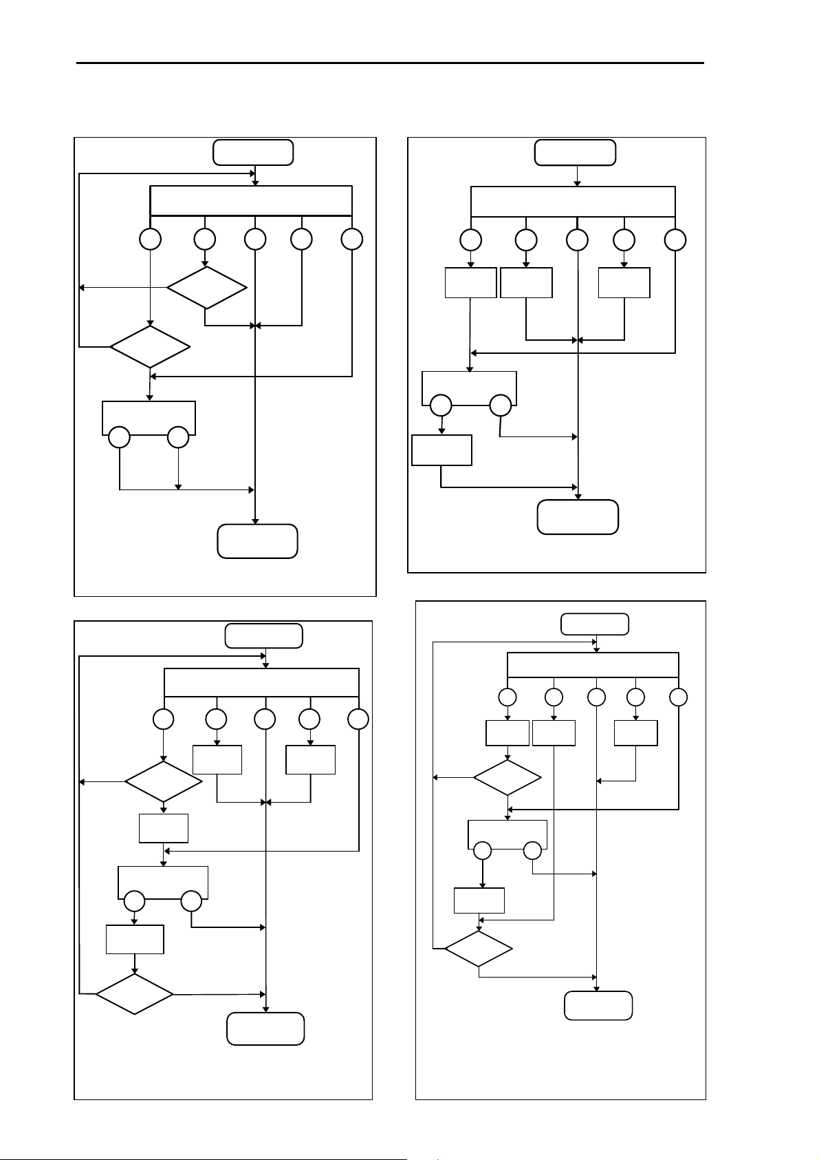
6.1.2.9 Restart mode
If batching is stopped by a tolerance alarm, or if a correction is possible with the weight below the
set-point, the defined restart mode determines the behaviour. A correction is possible with the batched
weight below fine switch-off point after the calming time. As a prerequisite, the tolerance test must
always be activated.
Weight
Tolerance band
Example in restart mode 4
After the calming time, the measured weight is below the low devia-
Set-point
tion. A new overshoot value is
calculated. If the difference to the
Overshoot
New overshoot
set-point is higher than the
overshoot value, a correction can
be started. After waiting again until the calming time has elapsed,
Calming time
the weight is within the tolerance
band, but still below the set-point.
Time
The overshoot value is corrected
again. Further correction is not
possible. With a tolerance alarm batching stops and the user has the opportunity for process intervention. In this case, the process can be continued ( Go ) or aborted ( A ) .
Calculation of modified overshoot values:
Setpoint - actual_weight
new_overshoot = old_overshoot -
corrected_overshoot = old_overshoot - (
2
Setpoint - actual_weight
)
Click on the required option field:
O no post-batching ⇒ mode 0
O post-batching, but no optimization ⇒ mode 1
O no post-batching, but optimization ⇒ mode 2
O post-batching first before optim. ⇒ mode 3
O optimization first before post-batch. ⇒ mode 4
Significations in the following diagrams
<T low deviation
<S weight below set-point
= set-point reached exactly
>S set-point exceeded
>T high deviation
Go entry: go on batching
A entry: abort batch
Mode 0
Batch
<
T
Tolerance alarm
Go A
<
S
=
Next
component
>
S
restart mode = 0:
Neither correction nor calculation of new
overshoot value
>
T
Page 29
Batching
PR1713 Operating manual
Mode 1
Batching
<
T
S
<
=
Y
Restart
N
Y
Restart
N
Tolerance alarm
Go A
Next
component
restart mode = 1:
Check only if correction is possible.
Mode 2
Batching
>
S
>
T
<
T
New
overshoot
S
New
overshoot
=<
>
S
New
overshoot
>
T
Tolerance alarm
Go
Corrected
overshoot
A
Next
component
restart mode = 2:
Calculate only a new overshoot in this mode.
Mode 3
Batching
=<
>S >T
New
overshoot
Y
Restart
overshoot
Tolerance alarm
Go A
Corrected
overshoot
J
Restart
<
New
T
N
S
New
overshoot
N
Next
component
restart mode = 3:
Test for correction and calculate new overshoot
Seite 30
Mode 4
Batching
S
=<
Next
component
>
S
New
overshoot
>
T
Y
Tolerance alarm
Go A
Corrected
overshoot
Y
Restart
<
T
New
overshoot
Restart
N
overshoot
N
New
restart mode = 4:
Calculate new overshoot and test for correction

PR1713 Operating manual
6.1.3 Deleting
Batching
Deleting individual or all component is with function
The entry is selected by scrolling
possible. The selection is completed with 'Enter'.
'Soft' key selection 'single' deletes only one selected component.
Unless the list is limited, all components are deleted: 'all'.
With a limited list, 'selected' is displayed instead.
Components, which are still used in recipes, must not be deleted.
'Soft' key selection 'show' displays the component name
and the first recipe in which this component is found.
If other components must still be deleted, the deleting operation is continued with 'soft' key selection 'next'.
• Key 'quit' can be pressed to leave submenu 'delete'.
. Limitation of the list is
!
'delete'
:
Select Component
firstname
!
!
Delete Component?
Single
All
Delete Component?
Single
Selected
Comp. used in recipe
Show
Next
6.1.4 Printing
!
!
Individual or all components are printed with function
Select the entry by scrolling !. A list limitation is possible.
Complete the entry by pressing 'Enter'.
'Soft' selection 'single' prints only one selected component.
Unless the list is limited, all components are printed with
'all'. With a limited list, 'selected' is displayed instead.
• Select submenu 'delete' with with key 'quit'.
'print'
:
Select Component
Sugar
!
Print Component?
Single
Print Component?
Single
Selected
All
!
Page 31

Batching
Quit
Quit
abc
Parameter value
remain unchanged
abc
changed parameter v alue
is accepted
With 'yes'all changes for this recipe
are accepted;
with 'no'they remain unchanged.
The recipe name is selected from a list by scrolling.
The list is shortend by entering the the first characters of the name.
123
6.2 Input menu for recipe editing
Recipe Table
Delete
is displayed by selecting softkey 'Recipe' from the batch menu.
6.2.1 Editing
Edit
Print
PR1713 Operating manual
Edit individual recipes with
Survey
at the editing function example
select recipe name
s e le c t line
:
'edit'
select recipe
Ø
Ø
Name
Recipe-name
Ø
Ø
27
×
×
Component name
Select recipe only w ith
×
×
store?
yes no
licenc e PR1713/21
Edt p aram eter v alue
f o r t h is lin e :
Component
← →
Setpoint
Flag for
rec ipe total
Flag for
Calculation m ode
Select component name
Ø
Ø
Zucker
Line setpoint
2
Total mode
1
Calculation mode
1
Seite 32
×
×
5 kg

PR1713 Operating manual
A
Batching
A number of specific parameters which shall be read out and changed as simply and quickly as possible is stored under the recipe name. The parameter set changes dependent of the batch mode.
Recipe name +...
Batchmode
B1 - B6
G1 - G6
D1, D2
A1
D3
A2
B8
D4 - D8
Rl, RQ, RL
01
line number
!
!
!
!
Component
Line setpoint
Total mode
Calulation mode
With the licence for multiple recipes (PR1713/21), recipes
could be selected or created. If not, this menue is skipped.
Select Recipe
!
!
Tart3
!
!
The recipe name selected last is displayed as proposal (e.g.
Tart3). It can be changed by selecting the available recipe
names. Limitation by list preselection is possible. A new recipe can be inserted in position '* new *'. 'Enter' completes
Select Recipe
!
!
* new *
!
!
the selection.
When trying to assign a recipe a name which was already assigned to another recipe, an error message is displayed.
Name already exist
OK
• Press key 'quit' to leave the entry of a new recipe.
The selected name is displayed in the upper line. In the lower
line, all parameters can be selected. The relevant line number
Tart18
!
!
1
!
!
Sugar1
is always displayed on the left. It can be edited first. The value of another parameter is displayed right beside the line number. The component name is displayed
first. The line number can be selected by 'scrolling' or by editing a value entry directly.
Note: There are no empty lines in the recipe.
With the first softkey, a selection for inserting or deleting a
recipe line is displayed.
Tart18
1
Insert
Delete
The second softkey is used for inserting a copy of the
actual line. The line numbers of the subsequent lines will increase by one.
The third softkey deletes the current line. The line numbers of the following lines decrease by
one.
When selecting a line number behind the last one used in this
recipe, a prompt whether another line shall be appended is
displayed. The number of lines must not exceed the configurated maximum number. The absolute maximum is 255 lines.
ppend new line
Yes
No
Page 33

Batching
PR1713 Operating manual
The component name can be selected by pressing 'enter'.
When pressing key 'enter' again, the other parameters are always displayed right beside the line number.
All parameters are always called up successively.
1) Component name
2) Set-point
3) Recipe total mode
4) Set-point scaling
The setpoint of the D3 component is a value in seconds and
has to be entered without a unit.
Select component
Sugar1
!
!
Line setpoint
52.4
kg
Total mode
1
Calculation mode
!
!
0
After completing the last parameter, the next line number is
always displayed automatically, so that a quick survey of all
data of a recipe is possible.
Note: Detailed explanations for the 'Total mode' are located in section 'Recipe total'. The
'Calculation mode' is described in section 'Setpoint scaling'.
• An entry can be completed by pressing 'enter'. The changes are stored. The next parameter of the
recipe line is displayed.
Tart18
2
!
!
Flour-3a
!
!
Seite 34

PR1713 Operating manual
p
g
p
g
p
g
g
g
p
g
g
g
g
g
g
Batching
6.2.2 Recipe total mode
It could be defined for the components B1-B6, G1-G6 and D1-D2, if the setpoints of the recipe line
should be added to the recipe sum. This marking is an element of the recipe line and not the component. The recipe sum is the base for the setpoint scaling. The recipe total mode is independing of the
calculation mode.
In this recipe with fill components, all batches are
added to the recipe total. In this example the recipe
Recipe
B1 80 kg
B1 40 kg
sum: 120 k
Recipe setpoint=120 kg
T
Markin
T
Recipe sum =
Start value of the reci
all lines with
Σ
T
When the recipe is extended by a B2- or B3component, then a
wrong recipe sum is
calculated. With the
extension of a B2component, the previous B1-component
must not used for the
80
70
40
B2
B1
recipe sum calculation.
The 'fil-up'-batch B2 is
based on the last tare
B1
from the B1 and contains in its setpoint so
to speak the setpoint of
the previous component. If using a B3 in-
Rest amount
when started
stead of the B2 component, only the B3-component must have the mark for the recipe total.
sum is calculated to 120 kg. If the recipe is started
with this amount, all components are batched with
exact the setpoints given in the recipe lines. Than
the recipe sum is the same as the recipe setpoint.
With a different recipe setpoint, all recipe line setpoints are adapted proportional.
e
GrossNet
weight
[kg]
160
130
90
10
nent 1
component 2
component 3
Recipe
B1 80 k
B1 40 k
B2 70 k
Sum: 150 k
Recipe setpoint=150 kg
time [t]compo-
T
T
Example:
e 1
Reci
B1 20 kg
B1 20 kg
D1 20 kg
Sum 60 k
T
T
T
e 2
Reci
B1 50 kg
B1 40 kg
B3 100 kg
Sum 100 k
e 3
Reci
B4 20 kg
B4 40 kg
T
B5 60 kg
Sum 80 k
T
T
Recipe 4
D1 100 kg
B2 120 kg
B3 150 kg
B1 20 kg
Sum 180 k
Recipe 5
B1 50 kg
B1 50 kg
B2 100 kg
B3 180 kg
Sum 200 k
T
When using components B2, B3, B5 and B6, pay attention to the correct setting of recipe total mode.
Page 35

Batching
g
g
g
g
g
g
6.2.3 Setpoint scaling
PR1713 Operating manual
The setpoints of each recipe line are recalculated according
to the recipe setpoint on each new recipe start. A setpoint
scaling is done. With the calculation mode it is defined, if
Scaling factor
_
Re _
cipe setpoint
=
Re _
cipe sum
the setpoint of the recipe line is recalculated on a new recipe start. In general all dosing components
will be scaled. The amount of the executed batch is changed by the scaling factor.
Example:
Recipe 1
B1 50 kg
B1 50 kg
B2 100 kg
Σ
Recipe setpoint=300 kg
Scaling factor = 2
TS
S
TS
150 k
real
batch
100 kg
100 kg
200 kg
300 k
Recipe 2
B1 50 kg
B1 50 kg
B3 150 kg
Σ
Recipe setpoint=300 kg
Scaling factor = 2
TS
150 k
real
batch
100 kg
S
100 kg
S
200 kg
300 k
Recipe 3
B1 50 kg 50 kg
B1 50 kg
B3 200 kg
Σ
Recipe setpoint=300 kg
Scaling factor = 1,5
TS
200 k
real
batch
S
75 kg
300 kg
300 k
In the third example the first component should not be scaled. Then the setpoint of the recipe line is
batched independingly of the scale factor.
The calulation mode is independing of the recipe total mode.
6.2.4 Simulation
Before each recipe start it is checked if this production could theoreticly run. All components for this
recipe must exist. During the recipe test run, neither the maximum weight of the hopper should be
excided, nor the weight should fall below zero. All weighing points must be free and should not be in
an error state. Without this conditions the recipe could not be started.
Seite 36

PR1713 Operating manual
6.2.5 Deleting
Batching
Deleting individual or all recipes with function
Select the entry by scrolling !. Limitation of the list is possible. Complete the selection by pressing 'Enter'.
'Soft' key selection 'single' deletes one selected recipe.
Unless the list is limited, all components are deleted with
'all'. With a limited list, 'selected' is displayed instead.
• Leave submenu 'delete' by pressing key 'quit'.
'delete'
:
6.2.6 Printing
Printing individual or all recipes with function
Select the entry by scrolling !. A list limitation is possible
with 'Enter'.
Press 'soft'key selection 'single' to print only one selected
component.
Unless the list is limited, all recipes are printed with 'all'.
With a limited list, 'selected' is displayed instead.
• Leave submenu 'delete' by pressing key 'quit'.
'print'
:
Select Recipe
firstname
!
!
Delete Recipe?
Single
All
Delete Recipe?
Single
Selected
Select recipe
firstname
!
!
Print recipe?
Single
All
Print recipe?
Single
Selected
!
!
!
!
Page 37

Batching
6.3 Starting a batch process
PR1713 Operating manual
Select recipe
Tart
!
!
Recipe setpoint
20.0
By selecting softkey 'Batch' from the batch menu, the PR1713
start procedure is displayed. The operator is prompted for
!
!
entry of recipe name, setpoint and number of cycles.
During configuration, a value can be assigned to individual or
each of these parameters. When starting the batch, these pa-
kg
rameters are not displayed for entry any more (e.g. the number of cycles is always one. An entry at each start is omitted.)
Number of cycles
1
6.3.1 Status display
During batching, the user can display the current process status.
• Gross weight
• Net weight
• Tare weight
• Difference weight
• Set-point
• Recipe name
• Component name
• Batch mode
• Current line
• Current cycle
• Maximum cycle
Tart7
3: Sugar4
B1 D -3.4 kg
7* S 10.0 kg
The status display has two levels. The display will change the level by pressing the key 'more'.
- In the first level the recipe name is shown in the upper line. In the lower line, the recipe line number and the actual component name are displayed.
- In the second level the batch mode, difference weight, number of current remaining cycles and setpoint are displayed. As long the first Soft-key is pressed, the maximum number of cycles are
shown.
With the Gross-key the weight display changed for a minimum of 3 seconds to the gross-weight.
With the Tare-key the weight display changed for a minimum of 3 seconds to the tare-weight.
6.3.2 Stopping the batch process
A batch process can be stopped manually at any time by pressing the red stop key. The stop
message is displayed blinkingly.
* stopped *
7* S 10.0 kg
Seite 38

PR1713 Operating manual
6.3.3 Continue, skip, abort
Batching
For this, the batch process must be in stop condition. When
pressing the stop key again, the following menu is displayed.
Pressing the first softkey resets the stop condition. In case
of a tolerance alarm, the recipe controller is instructed to go on operating. Dependent of error cause and restart mode, the operation is continued by postbatching.
When pressing the second softkey, the current recipe line is skipped. All following recipe lines are
continued normally. In case of a tolerance alarm, the recipe controller is instructed to abort only
this line, because the error cannot be removed, but the recipe can be continued.
When pressing the third softkey, the overall recipe is aborted.
• The menu is left again with the quit key.
skip abort
continue
line
recipe
6.3.4 Messages during batching
If tolerance monitoring is activated by entry of the tolerance
parameters above zero, a tolerance alarm can be generated
after a batch. If the currently batched total exceeds the tolerance, this message blinks in the first line and the recipe goes to the stop condition automatically.
Different reactions on a tolerance alarm are possible. See section: 'Continue,skip, abort'
* tolerance alarm *
7* S 10.0 kg
With flow monitoring activated by entry of the min. flow value, there may be a flow warning after a batch. If the material
flow exceeds the min. flow rate (e.g. due to clogging), this
message blinks in the first line. The recipe does not go to the stop condition, but continues checking
the flow rate. The warning extinguishes automatically, when the error is removed.
* flow warning *
7* S 10.0 kg
Page 39

Batching
PR1713 Operating manual
6.4 Selecting a report
is displayed by selecting softkey 'Report' from the batch menu.
Report
Consum
The following reports are selectable:
• component consumption report
• recipe production report
• last batch report
The layout of all reports is programmed with IEC1131. With the programming licence, however, the
user is able to match the reports to his requirements.
With the configuration, the physical interface is determined via configuration, where the report is
printed.
The reports have to be activated in the configuration. At 'Setup' und then 'Software parameter', it could
be selected if and for what purpose the recipecontroller generates a report.
'Report to ' none no report is generated
Prodct
communication only for communication.
proloc only for the user interface (IEC 1131 programs)
communic. & proloc for communication and user interface
LBatch
Note: Alle generated reports have to be read and deleted. If reports are generated for eg. com-
munication and user interface, the communication has to detete the batch reports. If not,
the data base is filled until no free memory space is left and no new batch could be started.
6.4.1 Consumption
Individual or all consumption totals can be printed out, or the
consumption values can be deleted by pressing the first softkey.
Select the entry by scrolling. A list limitation is possible. The
selection is completed by pressing 'Enter'.
'Soft' key selection 'Clear' clears one or more consumption
totals.
'Soft' key selection 'Show' shows one or more consumption
totals. By pressing a key, the consumptions are displayed
one by one. Pressing key 'quit' the list is aborted.
'Soft' key selection 'Print' prints one or more consumption
totals.
• Unless the list is limited, all consumption totals are taken
with 'all'. With a limited list, 'selected' is displayed instead. 'Soft' key selection 'single' taks only
one selected component.
• Pressing key 'quit' leaves the respective submenu.
Select Component
firstname
!
!
Consumption
Clear
Show
Print
Clear
Single
All
Show
Single
Selected
Print
Single
Selected
!
!
Seite 40

PR1713 Operating manual
Consumption report
Date: 17.06.99 13:56
Component WP Consumption
---------------------------------------- Sugar-640 A 558,4 kg
Sugar-210 A 24,3 kg
Flour-fine A 1330,8 kg
Egg powder A 572,0 kg
Spice mixture-25 A 0,0 kg
Spice mixture-30 A 0,0 kg
Spice mixture-38 A 104,3 kg
6.4.2 Production report
Batching
Pressing the second softkey prints out individual or all production totals or deletes the production total values.
!
Select the entry by scrolling. A list limitation is possible.
Complete the selection by pressing 'Enter'.
'Soft' key selection 'Clear' clears one or more production
totals.
'Soft' key selection 'Show' shows one or more production
totals. By pressing a key, the productions are displayed
one by one. Pressing key 'quit' the list is aborted.
'Soft' key selection 'Print' prints one or more production
totals.
• Unless the list is limited, all production totals are taken
with 'all'. With a limited list, 'selected' is displayed instead.
'Soft' key selection 'single' taks only one selected recipe.
• Leave submenu 'delete' by pressing key 'quit'.
Production report
Recipe Production total
------------------------------------- Biscuits 502,0 kg
Cookies 338,1 kg
Sand cake 1847,4 kg
print
Select Recipe
firstname
!
!
Production
Clear
Show
Print
Clear
Single
All
Show
Single
Selected
Print
Single
Selected
!
!
Page 41

Batching
PR1713 Operating manual
6.4.3 Last batch report
Printing the last batch report with the third softkey:
Note: In the configuration, 'Setup' and then 'Config', it could be selected if an actual batch re-
port is printed automatically after each batch. Therefore the menue 'batchep.auto prt' has
to be selected to 'auto'.
Maier-Keks GmbH
The world of biscuits
Batch report
Date: 03.10.99 12:35
Recipe: cookies
Sequence number: 476
Total: 100 kg
Production number: 12
Customer number: 1
Start time: 12:01
Stop time: 12:08
Chargenumber: 1/3
Alarmflags: none
Line Component Actual value Setpoint Error
----------------------------------------------------------------- 1 Flour-fine 1502,0 kg 1502,0 kg 0
2 Sugar-210 738,1 kg 738,1 kg 0
3 Egg powder 347,4 kg 347,4 kg 0
4 Spice mixture-38 82,9 kg 82,9 kg 0
Seite 42

PR1713 Operating manual
Batching
6.5 Address layout of signals
6.5.1 Digital in- and outputmodules PR1713/12.
Note: The functionality descibed here, is the PLC standard program. This program could be changed
with the software tool PR1750.
The output of the internal states or the input of 'commands' is defined by plugging the digital I/O cards
(PR13/12) in the slots. Depending on the inserted licences the PR1713 has two operating modes: the
indicator operation and the batch operating.
Indicator operation
Without a dosing licence PR1713/20 or PR1713/21
The indicator operation needs no further configuration.
Slot 1
if the digital I/O-modul
PR1713/12 is plugged
in
Slot 2
if the digital I/O-modul
PR1713/12 is plugged
in
Slot 3
Inputs
tare in B12
tare out B34
set to zero B56
weight valid B78
on terminal
Outputs
standstill A12
¼ d indication A34
tared A56
free A78
Limit 1 on WP-A A12
Limit 2 on WP-A A34
Limit 1 on WP-B A56
Limit 2 on WP-B A78
on terminal
Batching operation
For the batching operation the licence
inputs the recipe could be controled: stop, restart, abort.
Depending on the configuration: 'Setup' and then 'Config' in the parameter: 'Comp.& recipe I/O:' two
variants exist: '
1)
For each Component a
The output addresses of the components had to be entered in the parameter SPM-out for each
component. The selection of the output is free.
For D1, D2, D5 and D8 components needs also the corresponding input addresses ('Quit' for
D1, D2 and 'Go on' for D5, D8)
Recipes could be started with the 'Start'-input. With the licence PR1713/21 for multiple recipes,
the recipe is started wich had been selected by one of the inputs of slot 2 or slot 3. Then the n-th
recipe from the alphabetic sorted list of recipes is taken.
single
' or '
binary
single
'.
PR1713/20 or PR1713/21
output is set and for each recipe a
has to be activated. With the digital
input is read.
single
Page 43

Batching
PR1713 Operating manual
Slot 1
if the digital I/O-modul
PR1713/12 is plugged
in
Slot 2
if the digital I/O-modul
PR1713/12 is plugged
in
Slot 3
if the digital I/O-modul
PR1713/12 is plugged
in
2)
The Component output is
Inputs
on terminal
Control signals
Start / Restart / quit B12
Stop B34
Abort B56
Go on B78
single signals
Start recipe 1 B12
Start recipe 2 B34
Start recipe 3 B56
Start recipe 4 B78
single signals
Start recipe 5 B12
Start recipe 6 B34
Start recipe 7 B56
Start recipe 8 B78
binary coded
and the recipe input is read
Outputs
batch control
coarse valve A12
fine valve A34
discharge A56
error A78
single signals
component 1 active A12
component 2 active A34
component 3 active A56
component 4 active A78
single signals
component 5 active A12
component 6 active A34
component 7 active A56
component 8 active A78
on terminal
binary coded
The output addresses of the components had to be entered in the parameter SPM-out for each
component. The selection of the output is free.
For D1, D2, D5 and D8 components needs also the corresponding input addresses ('Quit' for
D1, D2 and 'Go on' for D5, D8)
Recipes could be started with the 'Start'-input. With the licence PR1713/21 for multiple recipes,
the recipe is started wich had been selected by one of the inputs of slot 2 or slot 3. Then the n-th
recipe from the alphabetic sorted list of recipes is taken.
.
Slot 1
if the digital I/O-modul
PR1713/12 is plugged
in
Slot 2
if the digital I/O-modul
PR1713/12 is plugged
in
Slot 3
if the digital I/O-modul
PR1713/12 is plugged
in
Inputs
on terminal
Control signals
Start / Restart / Quit B12
Stop B34
Abort B56
Go on B78
Start recipe binary coded
20 B12
1
B34
2
2
B56
2
3
2
B78
Start recipe binary coded
24 B12
5
B34
2
6
B56
2
7
2
B78
Outputs
on terminal
batch control
coarse valve A12
fine valve A34
discharge A56
error A78
Component binary coded
20 A12
1
A34
2
2
A56
2
3
2
A78
Component binary coded
24 A12
5
A34
2
6
A56
2
7
2
A78
Seite 44

PR1713 Operating manual
Batching
6.5.2 SPM-addresses for addressing the digital outputs
All addresses in the parameter 'SPM-out' of the component had to be between 1024 and 1279. If the
component active signals are routed individual to the outputs (single-mode) only the lower eight addresses 1024 to 1039 could be used.
With the binary coded output mode a maximum of 255 different components could be coded. Only
one component at the same time may be active.
%MX1024 Free marker range for component output (256 bits)
to
%MX1279
%MX1280 Free marker range for recipe number input (32 bits)
to
%MX1311
%MX1312 'Quit'-input for 'manual'-component on WP-A (internal WP)
%MX1313 'Quit'-input for 'manual'-component on WP-B (external WP)
%MX1314 'Go on'-input for 'wait'-component on WP-A (internal WP)
%MX1315 'Go on'-input for 'wait'-component on WP-A (internal WP)
%MX1344 activate the waiting background task.
%MX1345 start a recipe
%MX1346... free for additional functions
%MX1360 recipe number
to
%MX1367
Output of single component signals
Slot 2
Address
1024
1025
1026
1027
terminal
A12
A34
A56
A78
Slot 3
Address
1028
1029
1030
1031
terminal
A12
A34
A56
A78
Page 45

Batching
PR1713 Operating manual
Output of binary coded component signals
Slot 2
Address
1024 LSB
...
1151 MSB
Value after coding
0
2
1
2
2
2
3
2
terminal
A12
A34
A56
A78
Slot 3
Address
1152 LSB
...
1279 MSB
Input signals for components
The components for manual weighing (D1, D2) need a 'Quit'-signal from the operator. The address of
the 'Quit'-input is 1312 and had to be entered at the component parameter 'SPM-in'.
Value after coding
0
2
1
2
2
2
3
2
terminal
A12
A34
A56
A78
The components which are waiting for the input signal 'Go on' (D5, D8), need the address 1314 at the
component parameter 'SPM-in'.
Seite 46

PR1713 Operating manual
A
Analog test
7 A
During the calibration of the device the test value is calculated automaticly and stored in the
EEPROM. This value is scaled to the full scale deflection (e.g. 5000).
When the test is activated, the measuring signal is disconnected from the loadcell. The displayed value appears without an unit on the weighing display. Depending on the calibration the value is displayed as the actual test value
or
as the difference between the original stored test value and the actual test value (e.g. 0000).
NALOG TEST
nalog test activ
The analog test remains activ, until it is terminated by 'Soft-key'-Stop or the Quit-key.
Stop
Page 47

Batching
PR1713 Operating manual
Seite 48

PR1713 Operating manual
Setup
8 S
Various functions can be selected during setup:
• Calibration
• Configuration
• Serial interfaces
• Display of board number
• Licence number management
• Initialization data print-out
• Set time
• Refresh display
• Reboot
These functions are described in the
Setup
!
!
ETUP
Config
Installation manual .
)
Menu item 'Config' permits adjustment of the parameters for
all operating functions.
!
!
Page 49

Setup
PR1713 Operating manual
Seite 50

PR1712 Operating manual
Error messages
9 W
HAT CAN BE DONE IN CASE OF TROUBLE
9.1 Error messages
9.1.1 Error messages on the weight display
Only the error statuses of the analog part are output on the weight display. They are displayed in code
as 'Error x' .
Display Signification/cause
Error 1 Internal computer overflow (faulty calibration values)
Error 2 The input voltage is above f.s.d. + overload
Error 3 The input voltage is below the permissible value of 36mV. However, the message can
also be due to an analog section or load cell error, or a cable break.
Error 7 Negative input voltage or faulty load cell connection
Error 8 ADC error, e.g. hardware defective or overloaded
weight display with unit
weight display without unit
error display
Error 7Error 3
input signal
0 mV
0
+1/4d-1/4d
f.s.d. f.s.d. +
overload
Error 3
Page 51

Error messages
PR1713 Operating manual
9.2 Error messages on the text display
These error messages are generated by the current application.
Display
Signification/cause
Dbase error Opening or writing a table in the database was not possible. The table
is reserved by another program, or not existing.
Tabelle is empty No table contents were found.
Name already exist An attempt to insert a new item with a name which already exists in
this table into the database was made. The names in a table must be
different.
Comp. used in rec. An attempt to delete a component which is used in a recipe was ma-
de. Therefore, the component must be removed from the recipe pre-
viously.
Start error: ## Error during batch start, ##=error number.
1: recipe table cannot be opened
2: unknown recipe
3: recipe line table cannot be opened
4: no recipe lines existing
5: material table cannot be opened
6: no material existing
7: unknown batch mode
8: internal error
9: no function module of this name existing
10: recipe lines are not numbered continuously
11: invalid PLC bit address
12: no function module existing
13: faulty function module type
14: parameter error in the function module
15: no free memory space
16: parameter error in the function module
17: invalid weighing point name
18: analog section not installed
19: simulation error
20: weighing point cannot be reserved
21: weighing point in error condition
22-29: internal
30: production table cannot be opened
31: production table cannot be written
32: a recipe is already running
33,34: internal
35: no free memory space
36: no licence for a production
37: negative set-point
38: too many active weighing points in the recipe
39: invalid weighing point
40: weighing point parameter in the request component is invalid
41: invalid batch mode for the reactor
42: no memory for the text parameter (recipe line, material)
43: invalid production line number
recipe not starting
The recipe controller was unable to handle the recipe.
Start timeout
no batch licence
PR1713/20 or /21
Batching licence PR1713/20 or PR1713/21 is required for handling
this function.
Analog test failed Analog test could not be activated. Weighingpoint is not free or in
error.
Seite 52

PR1713 Operating manual
Index
10 I
NDEX
A
alarm indicaton................................................................ 6
Analog components.......................................................26
analog input component................................................ 26
analog output component.............................................. 26
analog test ..................................................................... 47
B
Back-space......................................................................7
batch
− abort recipe ............................................................. 39
− continue .................................................................. 39
− skip line................................................................... 39
− start ......................................................................... 38
− stop ................................................................... 38; 39
Batch Mode................................................................... 23
Batchable components..................................................23
Batching active indication............................................... 6
batching functions......................................................... 19
D
delete................................................................................7
discharge mode..............................................................24
Dummy components......................................................25
E
Enter key..........................................................................7
error messages................................................................51
F
fine switch-off point.......................................................29
fixed tare........................................................................15
flow warning..................................................................39
Flowrate.........................................................................28
Function keys...................................................................7
C
calculation mode.....................................................35; 36
Calming time........................................................... 28; 29
charge/discharge batching............................................. 24
component
− delete....................................................................... 31
− editing ..................................................................... 20
− print out .................................................................. 31
component signal
− binary coded ...................................................... 43; 46
− single................................................................. 43; 45
Configuration................................................................ 49
consumption .................................................................. 40
correction ...................................................................... 29
counting scale................................................................ 17
Cursor key....................................................................... 7
cycles............................................................................. 38
G
gross discharge mode.....................................................24
I
Input signals for components.........................................46
Page 53

Index
PR1713 Operating manual
L
last batch report............................................................. 42
M
main menu.....................................................................13
manual...........................................................................24
manual control...............................................................24
More key..........................................................................7
N
Q
Quit-key .......................................................................... 7
R
Recipe
− delete....................................................................... 37
− edit .......................................................................... 32
− print out................................................................... 37
recipe setpoint...............................................................36
recipe sum.....................................................................35
recipe total mode........................................................... 35
Reports.......................................................................... 40
restart mode................................................................... 29
RW, RQ, RL..................................................................25
net discharge batching...................................................24
O
Other batch modes.........................................................26
Overshoot......................................................................27
overshoot correction......................................................27
P
post-batching.................................................................2 7
PR1713/06.....................................................................26
Preset Point....................................................................27
print-out-key....................................................................7
production totals............................................................41
S
scaling...........................................................................36
Scroll key ........................................................................ 7
set to zero........................................................................ 7
set-point ........................................................................ 29
Setup ............................................................................. 49
simulation...................................................................... 36
Softkey........................................................................7; 8
SPM input address ........................................................ 27
SPM output address ...................................................... 27
Standstill ......................................................................... 6
Stop- key.........................................................................7
T
tare set and reset.............................................................. 7
Tolerance....................................................................... 27
tolerance alarm........................................................ 29; 39
tolerance test ................................................................. 29
total discharge...............................................................24
Seite 54
 Loading...