

Page 1

16/24 Ports PoE switch
User Manual
Page 2
Pre f a c e
Th e use r man ual mainly in tr od uc es the prod uc t app ea ra nce,
sp ec if ic at ion, ha rd wa re in st al la ti on, Web m an ag em ent a nd
ot he r re la te d information .
(2) V a r iou s S i gns
Imp rope r opera tion m ay dam age th e devi ce or cau se dat a loss .
Sup plem ental i nstr ucti on for o perat ion co nten ts.
Format
Description
< >
[ ]
/
Ill u s t rat i o n
(1 For m a t o f Gra p h ics I n t e rfa c e)
“<>”me ans bu tton n ame, su ch as “cli ck <Co nfir m> but ton”.
“[ ]”mea ns win dow na me, me nu name a nd dat a tabl e, suc h as“pop o ut [New
use r] win dow”.
“/” - . [ / / ] -
men u [fil e] men u [new] sub-m enu [f older ] menu o ptio n.
is us ed to se pera te Mult i l evel m enu S uch as fi le n ew fol der mul ti l evel
Cau tion
Ins truct ion
Content
1
Product Introduction
1
1 1. Overview
1
1 2.
Board Diagram
1 3.
Specification
2
1 4.
Pr o du c t Fe a tu r e
3
2
Installation
4
2 1. Shipping List
4
2 2.
Installation Precautions
4
2 3.
Installation Way
6
2 3 1. .
Rack Installation
6
2 3 2. .
Workbench Installation
7
2 4.
Cable Connection
8
2 4 1. .
Device Connection
8
2 4 2. .
Configuration Cable Connection
2 4 3. .
Power Line Connection
3
PoE Web Management Page
3 1.
Preparation Work
3 2.
Set up Network Connection
3 2 1. .
Set Stastic IP Address of Managed PC
3 2 2. .
Co n fi r m th e N et w or k C on n ec t io n b y Pi n g Co m ma n d
3 2 3. .
Cancel the Proxy Server
11
3.4
Typical Application
22
1
2 3 3. .
Wall-hung Installation
7
3 5.
Troubleshooting
22
3 3.
Operating Guidance of Web
3 1.3.
St a rt a n d Lo g in
3 3 2. .
Operating Instruction of Web
14
12
8
8
9
11
9
9
9
2 1.2.
Safety Precautions
4
2 2.2.
Installation Requirements
5
2 3.2.
The Requirements of Electromagnetic Environment
5
12
Page 3
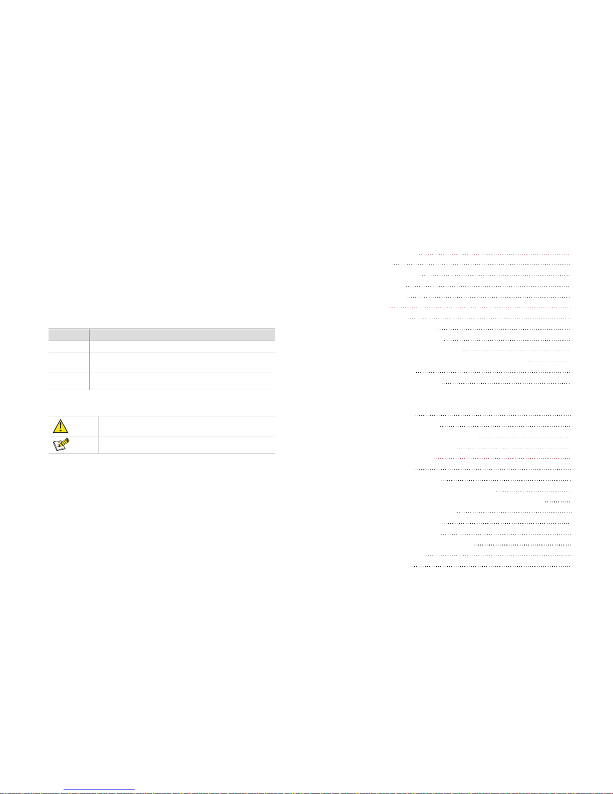
1 3 Board Diagram.
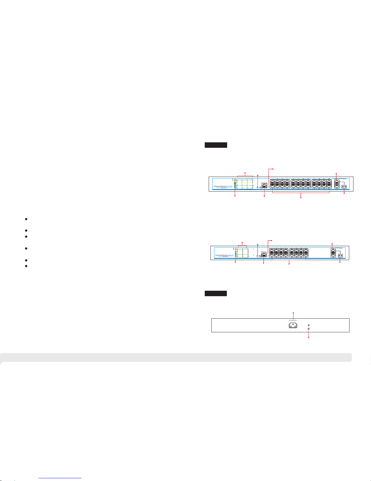
Bac k panel
Fro nt pane l
1 2
1 Product Introduction
1 1 Overview.
1.2 Product Feature
The 16/ 24 port s Po E switc h is an unma nag ed PoE Ethe rn et swit ch alon g wit h
16/ 24 * 1 00B ase-T X do wn lin k Po E por ts a nd 2 * 100 0Ba se- TX up lin k Ethe rne t
por ts fea turin g 3 0-w att 802. 3at Po E+ as wel l as 1 a dd iti ona l Giga bit Co mbo
por t. The tot al P oE p ow er b udg et i s up to 2 50/ 370 wa tt s. I t su ppo rts web -base d
PoE m ana gemen t and re al- ti me PoE o utp ut LE D dis pla y.Th e dev ice ca n be
wid ely use d in vide o secur ity mon itori ng syst ems, netw ork p roj ec ts, e tc.
Upl ink
Gig abit Po rts
Upl ink
Gig abit SF P
Com bo Port
PoE O utput P orts
PoE W eb
Man ageme nt
Por t
PoE O utput
LED
Res et
PoE O utput
Per centa ge
LED
PoE O utput P orts
Res et
PoE W eb
Man ageme nt
Por t
PoE O utput
LED
Upl ink Gig abit
Por ts
PoE O utput
Per centa ge
LED
24 Po r t s PoE sw i t ch
AC1 00~24 0V
Gro undin g Term inal
16 Po r t s PoE sw i t ch
Pro vide 16 24x 100 Mbp s do wnl ink Po E Eth ernet por ts, 2x gi gab it u pli nk
Eth ernet p orts an d 1x giga bit Fib er port ;
Dow nlink E thern et port s suppo rt PoE+ , each po rt supp orts ma x. 30W ou tput;
Sup port po wer cons ump tio n i nd ica tio n( LED i ndi cat es powe r output st atu s);
sup port ma nage Po E on/of f and p ower co nsump tion se tting v ia Web;
Acc ord wit h I EEE 802. 3、 IE EE8 02.3 u、 IE EE8 02 .3 ab、 I EEE 802 .3 af /at
sta ndard ;
4K MA C addre ss,2. 75Mb c ach e;
Qui ck i nst all ation , e as y o per at ion , con ven ient fo r wa ll- mo unt ed、 d esk top
and r ack ins talla tions .
/
Upl ink
Gig abit SF P
Com bo Port
CCT V
Mod e
CCT V
Mod e
Page 4

1.4 Specification
Tra nsm iss io n dist anc e is rela ted wi th the ca ble , we sugg est to us e
sta ndard C at5e/ 6 netwo rk cabl e to get th e best tr ansmi ssion r esult .
Pro ducts a re subj ect to ch ange wi thout p rior no tice
3 4
Caut io n
2 Installation
2 1 Shipping List.
2.2 Installation Precautions
To avo id dev ice dam ag e or per son al inj ury by i mpr oper u se, pl ea se o bse rve the
fol lowin g preca ution s.
P
con tact yo ur loca l deale r.
lea se chec k the f oll ow ing i tem s bef ore i nst allat ion , if an y mis sing, p lea se
Item Name
Quantity
Unit
1
Device
1
Set
2
AC Power Line
1
Piece
4
Accessories
1
Set
3
User Manual
1
Piece
Thi s is leve l A prod uct, w hic h ma y cau se r adi o in ter fer en ce in liv ing
env ironm ent. U sers m ay nee d to tak e co rre sp ond ing and eff ect ive
mea sures t o solve t he prob lem.
Ant i co unt erf eitin g la bel is attache d to the inj ector 's c ove r, so pro duc t
dam age c aus ed b y una uth ori ze d di sas se mbl y is no t c ove red un der
war ranty.
-
2.2.1 Safety Precautions
Caut io n
Inst ru ction
Ite m
Des cript ion
Pro duct Typ e
Pro duct Typ e
16p orts
24p orts
Por t
Des cript ion
Dow nlink E thern et Port s
16× RJ45, PoE+ 10 /100 Base- TX
24× RJ45, PoE+ 10 /100 Base- TX
Upl ink Eth ernet P orts
2* 10/ 100/ 100 0Base -T+ 1*1 000Ba se-X (com bo)
Pow er Inpu t
1×A C Femal e Term inal
Gro undin g Term inal
1×G round ing Termi nal
PoE &Powe r
Pow er Inpu t
Mai ns on loa d,100~2 40VAC 50/ 60 Hz
PoE P ower Su pply
End -spa n(1/2,3 /6), IEEE8 02.3 a f/at
PoE M ax. Pow er Outp ut
250 W
370 W(340 W if 110V AC inp ut)
Sin gle Por t Power O utput &
Volt age
Sin gle Por t PoE Pow er Outp ut≤30W, Vo ltage 5 4VDC
PoE We b
Man ageme nt
PoE M anage ment
Via We b( Defa ult IP Add ress 19 2.16 8.1. 200 ) to chec k, on/o ff and
adj ust eac h port Po E outpu t
Res et Butt on
PoE We b Reset
Lon g-pr ess 3s, a ll Link L ED soli d on abou t 10s, sw itch re set to fa ctory
def ault; s hort- press t o resta rt.
One -key CC TV
CCT V Mode
1. Do wnlin k ports o nly com munic ate wit h uplin k ports ;
2. Re strai n netwo rk stor m under 2 Mbps
Net work
Par amete rs
Net work St andar d
IEE E 802. 3,I EEE 802 .3u, IEE E 802.3 a b
Tran smiss ion Dis tance
100 m(Max .)
Exc hange C apaci ty
.7 2 Gbps
8. 8Gbp s
Pac ket Tran sfer Ra te
6. 55Mp ps
5. 36Mp ps
MAC Ad dress
4K
Pac ket Dat a Cache
2. 75Mb
Ind icato rs
Sta tus
Pow er Inpu t
1x Re d LED
Dow nlink E thern et Port s
Lin k:16x G reen LE D
PoE :16x Yell ow LED
Lin k:24x G reen LE D
PoE : 24x Yello w LED
Upl ink Eth ernet P ort Lin k
2x Gr een LED
PoE P ower Ou tput Pe rcent
10x L ED(In cludi ng 7x Gre en, 2x Yell ow, 1x Red ), sepa ratel y indic ate
10%、2 0%~100%
Pro tecti on
Lev el
ESD
/ - -6KV 8KV, Pe r:IEC 61000 4 2
Sur ge Prot ectio n
6KV , Per: IEC6 1000- 4- 5
Ope ratio n
Env ironm ent
Ope ratio n Temp eratu re
- ℃ ~ ℃10 45
Sto rage Temp eratu re
- ℃40 85℃~
Hum idity (Non -cond ensin g)
0~95%
Mec hanic s
Dim ensio ns(L xWxH)
442 * 207 * 44. 5mm mm mm
Mat erial
Iro n
Col or
Bla ck
Page 5

5 6
Pul l out the po wer pl ug b efore clean ing t he s witch . Do n ot use wet cl oth nor
liq uid to wi pe or was h the swi tch;
Do n ot le ave the s wi tch c los e to w ate r or wet p lac e so as to pre ve nt wa ter or
dam pness f rom ent ering i nto the s witch ;
Mak e sure th e swi tch w ork i n a cle an en vir onm ent . Ex ces siv e dus t may
cau se ele ctr ost at ic ad sorpt ion , wh ich w il l aff ect the e qui pment lif e an d cau se
com munic ation f ailur e;
The swit ch w ill work norm all y und er th e c or rec t v ol tag e. Pleas e en sur e the
vol tage in dicat ed on the s witch c orres ponds t o the pow er volt age;
To a voi d the dan ger of elect ric sho ck , p lease do not ope n th e swi tch cas e.
Do no t open th e switc h case ev en if the s witch i s power ed off;
The acc essor ies (i nclud ing but not lim ite d to po wer lin es , et c.) , wh ich can be
use d for the s witch o nly, is p rohib ited fo r other a pplic ation s.
The de vice sho ul d work in in doo r enviro nme nt to av oid th und er str ok e. It is
imp ortan t to obe y the fo llo wing re qui rem en ts no matt er yo u inst all it in the
cab inet or o n the wor kbenc h direc tly:
Eno ugh s pac e ( lar ge r th an 10c m) fo r a ir o utlet so as to fa cilit ate t he hea tin g
dis sipat ion;
Goo d venti latio n syste m for cab inets a nd work bench ;
Cab inet an d wor kbe nch i s stur dy enou gh to su ppo rt th e inj ect or an d it' s
acc essor ies's wei ght ;
Cab inet an d workb ench ha ve good g round ing.
Whe n it is wo rki ng, the swi tch may be aff ect ed by ex ter nal inte rfe re nce outs ide
the syst em thr ough th e w ays of r adi ati on and c on duc tio n. Pl eas e p ay att entio n
to th e follo wings :
AC pow er s up ply is T N system , so it is n ecess ary to use sin gl e ph ase po wer
soc ket (PE) wh ich c an p rot ect g ro und w ire s o th at th e fil ter c irc uit c an
eff ect iv ely f ilt er ou t the pow er grid d istur bance s;
The swi tch sho uld wor k far awa y fro m hig h-p ower radi o tra nsmit ters, rad ar
tra nsmit ters, h igh-f reque ncy dev ices;
Use e lectr omagn etic sh ieldi ng if nec essar y, such a s shiel ded cab le;
Int erfac e c abl es shou ld be arra nge d in doo r rathe r than outd oor to prev ent
ove r-vol tage an d over- curre nt caus ed from d amagi ng to the s ignal p ort.
2.2.2 Installation Requirements
2 2 3. . The Requirements of Electromagnetic Environment
The re are 3 in stall ation w ays: ra ck, wor kbenc h and ins talla tion. wal l-hun g
Ins talla tion pr ocess
(1) C heck ra ck grou nding a nd stab ility ;
(2) U se scre ws to fit h anger s at the de vice bo ard sid e;
:
Figure 2-1 Install hangers diagram
(3)
pro per pos ition
(4)
Put th e devi ce on the ra ck’ s brac ket an d move the ra ck alo ng the sl ot to
;
Use scr ews to fit the inst all ation han ger at rac k’s fix ed slot, mak e sur e the
dev ice is in stall ed at rac k’s bra cke t stead il y.
Figure
2 2- Install switch to the rack
Ple ase pu ll o ut t he p owe r li ne befo re i nst allin g or mov ing th e swit ch.
Gro undin g an d a nt i-l igh ten ing can grea tl y i ncr ease the pro te cti on level of
the swi tch. p lea se c onnec t the ea rth te rmi nal to t he e art h by u sin g at least
wir e 20.
Caut io n
2 3 . Installation Way
2 3 1. . Rack Installation
Page 6

2.4.3 Power Line Connection
( ) h e sa me as t he powe r of
(2 )
1 C hec k if t he s ele cte d po wer i s t ;swi tch
Con nect one si de of swi tch ’s pow er lin e with the sw itc h' s AC pow er por t,
and c onnec t the oth er side w ith AC pow er sock et;
(3 ) Che ck if switc h's AC p owe r indi cat e lig ht is on. T he li ght me ans p owe r
con necte d corre ctly.
2 4 Cable Connection.
2 4 1 Device Connection. .
U se c ro ss n et wo rk c ab le or cro ss -o ve r ca bl e to c on ne c t P C o r
oth er devi ce with s witch 's Ethe rnet po rt.
2 4 2 Configuration Cable Connection. .
Use a n etw ork c able to c onn ect con sol e p or t a nd ma nagem ent PC, u se
man ageme nt PC to co nfigu re the Po E switc h.
Thi s pr od uct ’s inst all ati on hang er s are jus t to fix the swit ch rath er than
sup port it. Use brac ket s un de r the dev ice (fi xed to the rack ) to supp ort
swi tch whe n insta ll the sw itch to t he rack .
2.3.2 Workbench Installation
You c an p ut t his pro duct o n cl ean , st abl e, gro unded wor kbe nch . The i nst all at ion
pro cedur e is as bel ow:
(1 )P ut t he de vic e ups ide dow n caref ully, cl ean t he g roo ves o n the c hassi s
bac kplan e with so ft clot h to make s ure the re is no oi l or dust i n it;
(2 )R em ove t he st ick ers on th e foot pa d, past e the foo t pa d in ba ckp lan e groov e;
(3 )P ut t he de vic e upr ight on t he work bench .
You al so c an p ut t he p rod uct on clea n, s tea dy v ert ica l wa ll. Ins talla tion
pro cedur e is as bel ow:
(1) Use t he sc rew s to f ix th e han ger s;
2.3.3 Wall-hung Installation
(2) Dri ll h ole s on t he s oli d po sit ion of w all a nd t hen dri ve t he ru bb er pl ug i nto the
hol e;
(3) Dr ive the se s cr ews int o th e ho le for the ra ck a nd f ix t he p roduct b y ai min g at
the r ubber p lug .
7 8
Figure
2-4
Fix the switch on wall
Figure
2-3 Hangers installation diagram
Inst ru ction
Figure
2-5 Connect configuration cable
Figure
2-6 Power line connection
Page 7

9 10
3 PoE Web Management Page
3.1 Preparation Work
3.2 Set Up Network Connection
3.2.1 Set Stastic IP Address of Managed PC
Thi s pr odu ct ha s W eb mana gem ent func ti on whi ch a llo ws user s t o con tro l and
man age PoE o f each po rt by log ging in o n Web pag e.
(1) You n eed to set the manageme nt PC a nd this injector IP address under
th e sa me net work segme nt, t hi s pr od uc t’s defau lt IP a dd re ss i s
192.1 68.1. 200, gate is 255. 255.255.0;
(2) If y ou need t o conne ct remo te netw ork, pl ease ma ke sure t he mana gement
PC and th e route r can make t his;
(3)Th is pro duct ca n't ass ign the IP addr ess for the man agement PC, yo u need
to set th e manag ement st atic IP by y ourse lf.
Ope ratio n steps ( take Wi ndows X P as samp le):
(1) Click <start> to enter the [start]
menu, select “control panel”. Double
cl ick “n etwo rk con ne ction ” i con ,
double click the “local connection”
icon, pop out “local connection status”
window.
Make sure the management PC has already been installed with Ethernet adapter;
Use network cable to connect the console port with management PC.
Inst ru ction
(2) Click <property> button, enter "local
connection property" window.
(3) Select "Internet protocol (TCP/IP), click
<property> button, enter “Internet protocol
(TCP/IP) property” window. Select “use
the IP address below” button, input IP
address( use arbitrary value between
192.168.1.1~192.168.1.254, besides
192.168.1.200) and the subnet
mask(255.255.255.0). Click"OK" to finish
the configuration.
DNS s erver a ddres s can be em pty or be f illed i n with th e real se rver
add ress.
Instruc ti on
Page 8

11 12
3 2 2 . . Confirm the Network Connection by Ping Command
Operati on S te ps as below:
(1)
menu, select [Run], pop out the dialog.
Click <Start> button to enter [Start]
(2)
<confirm> button. If there is equipment
response shown in the pop out dialog, that
means network connection succeed,
otherwise please check if the network
connection is correct.
Input "ping 192.168.1.200", click
3 2 3 . . Cancel the Proxy Server
If this management PC uses proxy server to visit the Internet, then you must prohibit
the proxy service, following is the operation:
(1) In browser, select [ tool/Internet
option] enter [Internet option] window.
3.3 Operating Guidance of Web
3 3 1 . . Start and Login
Th is p ro duc t w eb d ef aul t I P a ddr es s: 1 92. 16 8. 1.2 00, su bne t m ask :
25 5.2 55. 255. 0, ad minis tra tor ac cou nt: adm in, p as swo rd: ad min. Af ter
ins talli ng t he e qui pme nt c orr ect ly a nd s ett ing up th e co mpu ter, ope n the
bro wser, inp ut the in jec to r d efa ult ad dre ss in the br ows er add res s bar :
, t hen pres s t he Ent er key, the u ser logi n p age will show in
fro nt of you a s follo ws:
htt p://1 92.16 8.1.2 00
The bro wse r ve rsi on re co mme nde d: IE7 and l ate r, Fire fox b row se r, Chr ome , 36 0
bro wser (I E7 and la ter).
(2) Sel ect con ne cti on ta bs i n [I nte rne t
opt ion] win dow, an d cl ick [LAN Set tin g]
but ton.
“ ”
(3) Make sure the “Use proxy server for LAN”option is not selected. If selected, please
cancel it and click <yes> button.
Page 9

The diagram of language change page
3 3 2 2 Setting IP Address. . .
(1) C lick th e Web man age ment pa ge
men u bar “IP ”, then I t will po pup a
dia log box o f setti ng IP add res s.
3.3.2 Operating Instruction of Web
3 3 2 1 Change Language. . .
As show n in the pictu re b elo w, pre ss t he drop -do wn list at th e i con , choos e
“Ch inese ” or “Eng lish” t o achie ve Web pa ge la nguag e, as the p ictur e below.
(2) Chan ge pr odu ct IP add res s, sub net
mas k an d g ate way at the dia log box of
set ting IP add res s, suc h as cha nge the
IP ad dres s to 192 .1 68 .2. 200, k ee p
sub net ma sk un cha nged, a nd ch an ge
def ault ga teway t o 192.1 68.2. 1.
(3) Af ter cha nging t he IP add res s, p res s the “ OK” b utton a nd wait f or 10 sec onds
til l produ ct IP add res s is s ucc ess ful ly chan ged.
13 14
Aft er inp utt ing th e cor re ct us er n ame and pa ssw ord , cl ick <Lo gin> an d th e
bro wser wi ll show t he prod uct Web m ana gemen t page as t he pict ure bel ow:
Ple ase fol low the s teps to c heck if t he inje ctor is i nstal led cor rectl y:
(1) W hethe r the phy sical c onnec tion of t he equi pment i s corre ct?
The o ther en d of the ne twork l ine tha t is conn ected w ith com puter
net work ca rd must c onnec t with th e injec tor Con sole po rt, and e nsure t he
lin k indic ator li ght of th e netwo rk port i s on.
(2) W hethe r the com puter T CP/ IP ag re eme nt se tti ng is cor rect?
Your c omp ute r’ s IP ad dre ss mu st be 192 .168. 1.x (x ra nge is1 ~254
and x c annot b e 200, it wi ll conf lict wi th the pr oduct I P
add ress: 1 92.16 8.1.2 00), s ubnet m ask : 255 .2 55. 255 .0
oth erwis e
.
Caut io n
Diagram of Web English management page
Page 10

Wha t to do whe n the pas sword i s forgo tten?
Ple ase ref er to 3.2 .2.4 to r estor e IP addr ess a nd p ass wor d.
3.3.2.4 Restore the Initial Setting
(1) C lick me nu bar [r estor e the ini tial se tting ] on the We b pag e, p opu p dia log b ox as
sho wn belo w:
Restore t he i ni tial settin g
(2) C lick <O k> butt on and re store t he init ial set ting, p ress <C ancel > b utton t o
can cel the r estor e of the in itial s ettin g.
(3) Af ter pre ssing < Ok> but ton, wa it for 10 s econd s, the pr oduct r estor es the
ini tial se tting .
To rest ore the i nitia l setti ng mean s to rest ore two m enu con figur ation
inf ormat ion of [P oE sett ing] an d [Port s tatus a nd cont rol] in t he Web to
fac tory de fault s ettin g, plea se use in c autio n.
15 16
(1) W hen pro duct IP a ddr es s is ch ang ed, p lease e nsure t hat the c omput er IP
add ress an d the pro duct IP a ddr ess mus t be i n the s ame n etw ork seg ment
and t he sett ings of s ubnet m ask and g atewa y must be c orrec t.
(2) When c han gin g pr odu ct IP a ddr ess , pl eas e ens ure t he powe r suppl y to
avo id abno rmal pr oblem s.
(3) What t o do if y ou fo rg et th e IP ad dre ss of t he p rod uct ? Ple ase ref er to
3.3 .2.5 re store t he init ial set ting.
3.3.2.3 Change Password
Log in pas swo rd: the produ ct only pr ovi des one us er name “ad mi n”, de fault
pas sword is “ adm in”,
and th e pa ssw ord len gt h mu st b e be twe en 5~ 20,
Ple ase chang e th e pass wor d in time for sys tem saf ety
Th e ch ang e wi ll tak e ef fec t
on ne xt logi n.
(1) Click t he Web ma nag ement p age
men u bar [ch ange pa sswor d], the n It
wil l pop up a di alog bo x of chan ging
pas sword .
(2 ) En ter th e p ro du ct c ur re nt
pas sword a nd th e new p ass wor d,
the n confi rm the ne w passw ord.
(3 )C li ck the < ok> ke y a nd then a
dia log box a s the p ict ur e wil l pop
up, c lick <C lose> .
Caut io n
Caut io n
Caut io n
Page 11

(1) Pow er inpu t: The tot al power p rovid ed by the pr oduct f or PoE supply, i.e. th e
power p rovid ed by built-in 54 V power, ha s been set u p when it l eaves th e facto ry,
pleas e do not mo dify it. If users m odified the pow er supp ly, please correct t his
setti ng. If th e settin g value i s larger than the a ctual p ower of th e built -in powe r
suppl y, there wil l be a dama ge of buil t-in po wer. If the se tting v alue is smaller t han
the act ual pow er of buil t-in po wer sup ply, built- in powe r suppl y could no t be full y
alloc ated ou t.
(2) Allow ing max imum overload : built -in powe r allow s overlo ad valu e settin g range
is 0%-1 0%, def ault is 5% . If actu al power is too lar ge that c ause bui lt-in p ower
overl oad exc eeding settin g value , the syst em will t urn off power supp ly of low
prior ity por ts. For ex ample :when input pow er is 360 w, maximum o verlo ad is 5%.
when ac tual ou tput power exce eds 360 *(1+5% )=378 w , the syst em over loads.
(3) Pow er Rese rvatio n: powe r reservation c ould no t be contr ibute d, but be us ed for
PoE equ ipmen t consumption d ue to loa d change s. Defa ult powe r reser vation i s
15% of to tal pow er. The high er the val ue, the s lower the risk of s ystem overloa d, the
power t o be cont ributed decre ases, and the num ber of Po E equipm ents to b e
conne cted de creases; on the c ontrary , the mor e the num ber of PoE e quipm ents to
be conn ected , the high er risk o f system overlo ad.
(4) Ope ratio n instru ction s: after settin g the val ue, pres s <OK> bu tton. Se tting
succe eds whe n the foll owing w indow p ops out.
3.3.2.9 Power Status
Power status page diagram
The i nput po wer, all owing m aximu m overl oad and r eserv ed powe r have
bee n set up be fore th e produ ct leav es the fa ctory. U ser i s al low ed to m odi f
it, p ruden tly.
3.3.2.8 PoE Setting
Diagram of PoE setting page
3 3 2 5 Restore IP Address and Login Password. . .
Sta rt the pr oduct , unplu g the net work ca ble of co nsole p ort, th en pres s init
key (3~5 seco nds), t ill the R J45 LED l ight of c onsol e port fl ash onc e, the IP
add ress an d login p asswo rd will b e resto red to th e initi al sett ing.
3 3 2 6 Equipment Information. . .
Cli ck menu b ar [equ ipmen t infor matio n] on Web p age , t he n thr ee pr odu ct
inf ormat ion of [I P add ress] , [MAC ad dress ] and [so ftwar e versi on] wil l be popp ed
out f or user c hecki ng. Afte r revie w, click < Exit> t o log out c hecki ng stat us.
Equipment information diagram
3 3 2 7 Exit. . .
Cli ck main m enu [E xit] to r etu rn to l og in pa ge.
Diagram of restore IP address, login password
17 18
Inst ru ction
PoE O utput P orts
PoE W eb
Man ageme nt
Por t
PoE O utput
LED
Res et
PoE O utput
Per centa ge
LED
Page 12

(3) P riori ty: the re are th ree por t power s upply p riori ty leve ls: low, m edium a nd
hig h. when s ystem o verlo ads, th e power s upply o f low pri ority p ort wil l be
dis conne cted fi rstly.
(4) Al lowed m aximu m outpu t power : set sin gle por t’s lim ite d outpu t power, t he
por t will be d iscon nect wi th powe r suppl y once ac tual po wer exc eeds th is valu e.
Eac h port of t he prod uct pro vides m ax 30W ou tput po wer. If us er sett ing exc eeds
30W, t he maxi mum out put pow er will o nly be 30 W.
(5) Ac tual ou tput po wer: po rt’s ac tua l ou tpu t pow er .
(6) F ault st atus al arm: Th e fol lo win g sit uat ions wi ll caus e warni ng info rmati on on
[pr ompte d messa ge]:
S urplu s power l ower th an 10W;
Tot al powe r overl oads ;
L inked P oE powe red dev ice’s ( PD) p or t dis con nec ted.
(7) O perat ion ins truct ions:
Ope n all th e po rts: pre ss tit le
bar , th en pop up dia log
box a s the fig ure sho wn:
Ope n sin gle port : p res s c orr esp ondin g por t ,a fte r set tin g s ucc ess,
pop up“se tting s ucces s”pro mp, and t he corr espon ding bu tton be comes
th e sys tem w ill check w het her t he port i s connect ed wi th Po E power ed
dev ice (PD ) autom atica lly. It st art s po wer s upp ly wh en chec king OK .
Clo se si ngle port: pres s cor respo nding port and popu p dia log box.
Take p or t 1 a s an exa mpl e, pre ss < OK> , p op up “ set up i s su ccess ful”. Wh en
set ting su cceed s, corr espon ding bu tton be comes .
(1) Ac tual ou tput: t otal ac tual ou tput po wer .
(2) S urplu s: the po wer to be u sed for r edist ribut e. Surp lus=i nput- actua l outpu tres ervat ion, pl ease no ted tha t the pro duct di strib utes po wer acc ordin g to powe r
lev el of det ected P oE powe red dev ice whe n conne cting a n ew PoE po wered
dev ice, in stead o f accor ding to t he actu al powe r of newl y conne cted Po E
pow ered de vice. F or exam ple: wh en surp lus pow er is 20W , i f the pow er leve l of
the c onnec ted PoE p owere d devic e is 25.5 W, the sys tem cou ld not di strib ute
pow er for it e ven if th e actua l power o nly nee d 10W, whi ch mean s it cann ot be
pow ered.
(3) R eserv ation : used fo r PoE pow ered de vice du e to load c hange s cause d by
con sumpt ion, fr om pare nt menu s ettin g “inpu t power * r eserv e power ”.
(4) i nput : Th e tot al p owe r of th e sys tem, fr om pare nt menu “ input p ower” .
3 3 2 10 Port Status and Control. . .
Port status and control page diagram
(1) P ort num ber: co rresp ondin g to the po rt numb ers on pr oduct b oard,
ind icate s unlin ked PoE p owere d devic e or link ed PoE po wered d evice w ithou t
pow er supp ly, in dic ates li nked Po E power ed devi ce and no rmal su pply.
(2) P owere d devic e locat ion: a br ief des cript ion of in stall ation l ocati on of
pow ered de vice’ s eac h port.
19 20
Page 13

Ple ase fin d the fol lowin g solut ion whe n the dev ice doe sn’t wo rk
Ple ase c onf ir m th e i nstal latio n i s c orrec t
Ple ase con firm wh eth er the seq uence of RJ45 cabl e mee t the EIA /TI A56 8A or
568 B indus try sta ndard s;
Ple ase r epl ace devi ce w hi ch c an not work wit h a pro perly work ing one t o ch eck
whe ther th e devic e is brok en;
Ple ase con tact th e facto ry if the p roble m stays u nsolv ed.
;
Tur n of f al l t he p ort s: pres s tit le bar b utton , pop up d ial og box as
sho wn belo w:
Pre ss OK , wh en al l th e po rts op en, popu p “set up is su cce ssf ul” , the
but ton bec ome sta tu s.
Set ting sin gle po rt par ame ter s : por t para met ers in clu de powe red dev ice
lo ca ti on, pri orit y a nd allo wed ma ximum ou tput pow er. A ft er s ettin g
par amete rs, p ress <O K> bu tto n o f the c orr esp on din g p ort , the n p opup
“se tting s ucces s” when o perat ion fin ishes .
Set ting a ll t he p ort par ame ter s : p res s [p ort con tro l an d st atu s] [ act ual out pu t
pow er(W) ] butto n, then p opup di alog bo x as show n below :
< >
Pre ss O K wh en a ll t he s ett ing fin ish es, pop up “se tup is suc ces sf ul” .
Set ting un ified a llowe d maxim um outp ut powe r: as sho wn belo w:
< >,
Aft er sel ect ing t he che ck bo x, al l t he ports al low m axi mum o utp ut po wer
dep ends on t his val ue.
Pre ss <O K>, whe n all the port ope ns, popu p “s ett ing s ucc ess ”, the bu tto n tu rn s
to st atus.
21 22
3 5 Trouble Shooting.
3.4 Typical Application
Th is prod uct desi gn is env iro nmen tal frien dl y. Pl eas e stor e, use an d di sca rd
th is p rodu ct in acc orda nc e wi th th e r ele vant nat iona l l ega l/ reg ulat ory
re qui reme nt s.
En vi r on me nt p r ot ec t i o n
Cat5/5e/6
LCD
display
NVR
s
wit ch
UT
P
1
-S
W24
T
P42 0
Fiber
PoE camera
PoE camera
PoE camera
PoE camera
 Loading...