

Page 1

USER MANUAL
1
Page 2

USER MANUAL
2
Contents
SAFETY INSTRUCTION
...............................................................................................
5
CHAPT ER 1 OVERVIEW OF NVR
..............................................................................
6
1.1 REAR PANEL
...........................................................................................................
6
1.2 REMOTE CONTROLLER (FOR REFERENCE ONLY)
..................................................
7
CHAPTER 2 NVR CONNECTION
...............................................................................
8
2.1 HDD INSTALLATION
.................................................................................................
8
2.2 IP CAMERA AND MONITOR CONNECTION
...............................................................
8
2.3 POWER SUPPLY CONNECTION
...............................................................................
8
CHAPT ER 3 NVR COMMON OPERATIONS
............................................................
9
3.1 USING THE SUPPLIED MOUSE
................................................................................
9
3.2 USING THE VIRTUAL KEYBOARD
.............................................................................
9
3.3 PASSWORD &LOCKING THE SCREEN OPERATION
.............................................
10
CHAPTER 4 NVR BOOT UP
......................................................................................
11
4.1 STARTUP WIZARD
..................................................................................................
11
4.2 M
AIN INTERFACE
...................................................................................................
14
CHAPT ER 5 NVR MENU
............................................................................................
15
5.1 O
VERVIEW
.............................................................................................................
19
5.2 D
ISPLAY
.................................................................................................................
20
5.2.1 IP Camera
.....................................................................................................
20
5.2.2 Live
.................................................................................................................
22
5.2.3 Output
............................................................................................................
23
5.2.4 Image Control
...............................................................................................
23
5.2.5 Privacy Zone
.................................................................................................
25
5.3 R
ECORD
................................................................................................................
26
5.3.1 Record
...........................................................................................................
26
Page 3

USER MANUAL
3
5.3.2 Record Schedule
.........................................................................................
27
5.3.3 Mainstream
...................................................................................................
28
5.3.4 Substream
.....................................................................................................
29
5.3.5 Mobilestream
................................................................................................
30
5.4 NETWORK
..............................................................................................................
31
5.4.1 Network
.........................................................................................................
31
5.4.2 Switch
............................................................................................................
32
5.4.3 Email
..............................................................................................................
33
5.4.4 Email Schedule
............................................................................................
34
5.4.5 DDNS
.............................................................................................................
34
5.4.6 RTSP
.............................................................................................................
35
5.4.7 FTP
................................................................................................................
36
5.5 ALARM
...................................................................................................................
37
5.5.1 Motion
............................................................................................................
37
5.5.2 Alarm
..............................................................................................................
39
5.5.3 PTZLinkage
..................................................................................................
40
5.6 RECORD SEARCH
.................................................................................................
41
5.6.1 General
..........................................................................................................
41
5.6.2 Events
............................................................................................................
41
5.6.3 Playback Video Recordings
.......................................................................
43
5.6.4 Play Backup Files
........................................................................................
48
5.7 D
EVICE
..................................................................................................................
51
5.7.1 HDD
...............................................................................................................
51
5.7.2 Disk Group
....................................................................................................
53
5.7.3 PTZ
................................................................................................................
54
5.8 S
YSTEM
..................................................................................................................
56
5.8.1 General
..........................................................................................................
56
5.8.2 DST
................................................................................................................
57
5.8.3 NTP
................................................................................................................
58
5.8.4 Users
..............................................................................................................
58
Page 4

USER MANUAL
4
5.8.5 Info
.................................................................................................................
60
5.8.6 Log
.................................................................................................................
61
5.9 ADVANCED
.............................................................................................................
62
5.9.1 Maintain
.........................................................................................................
62
5.9.2 Events
............................................................................................................
63
5.10 INTELLIGENT
........................................................................................................
64
5.10.1 Schedule
.....................................................................................................
64
5.10.2 PID(Perimeter Intrusion Detection)
.........................................................
65
5.10.3 LCD(Line Crossing Detection)
.................................................................
67
5.10.4 SOD(Stationary Object Detection)
..........................................................
70
5.10.5 PD(Pedestrian Detection)
........................................................................
72
5.10.6 FD(Face Detection)
...................................................................................
74
5.10.7 CC(Cross-Counting)
..................................................................................
76
5.10.8 View Log of Intelligent Analysis
...............................................................
79
5.11 SHUTDOWN
..........................................................................................................
80
CHAPT ER 6 WEB APPLICATION MANAGER
......................................................
81
6.1 WEB PLUGIN DOWNLOAD AND INSTALLATION
.....................................................
81
6.2 W
EB CLIENT MANAGER
........................................................................................
84
6.2.1 Live Interface
................................................................................................
84
6.3.1 Playback
........................................................................................................
86
6.3.2 Remote Setting
............................................................................................
91
6.3.3 Local Setting
.................................................................................................
91
CHAPT ER 7 REMOTE ACCESS VIA MOBILE DEVICES
....................................
92
CHAPT ER 8 APPENDIX
.............................................................................................
95
8.1 T
ROUBLESHOOTING
...............................................................................................
95
8.2 USAGE MAINTENANCE
..........................................................................................
96
8.3 S
YSTEM CONNECTION DIAGRAM
..........................................................................
96
8.4 A
CCESSORIES (GOODS IN KIND PREVAIL)
............................................................
97
Page 5

USER MANUAL
5
SAFETY INSTRUCTION
Please carefully read the following safety instruction so as to avoid personal
injuries and prevent the equipment and other connection devices from being
damaged.
1. Power sources (note: please use the power supply attached or specified
by the manufacturer)
Never operate the equipment by unspecified power supply.
2. Never push objects of any kind through openings of NVR;
Never push objects of any kind through openings of NVR so as to avoid electric shock or
other accidents.
3. Do not put the equipment in the dusty field;
Do not put the equipment in the dusty field.
4. Do not place the equipment under rain or humid environment
Do not place the equipment under humid environment like basement. If the equipment is
in contact with water, please unplug the power cable and immediately contact your local
dealer.
5. Keep the surface of the equipment clean and dry
Use soft damp cloth to clean the outer case of NVR (do not use liquid aerosol cleaners)
6. Do not operate if any problems are found
If there are any strange smell or sound, unplug the power cable and contact the
authorized dealer or service center.
7. Do not try to remove the upper cover
Warning: Do not remov e the cap of NVR so as to avoid electric shock.
8. Handle with care
If NVR does not work normally because of hitting on the hard object, please contact the
authorized dealer for repair or replacement.
9. Use standard lithium battery (Note: Use the batteries attached or specified by the
manufacturer)
After cutting off the power supply, if the system clock cannot continue to work, please
replace the standard 3V lithium battery on the main board.
Warning: Turn off NVR before replacing the batteries, or you may be suffered from
serious electric shock. Please properly dispose of the used batteries.
10. Put the equipment in a place with good ventilation.
The NVR system includes HDD, which produces large amount of heat during operation.
As a result, do not block the ventilation openings (on the top, bottom, both sides and the
reverse side) for cooling the system during operation. Install or put the equipment in the
place with good ventilation.
11. The attached power adapter can only be used for 1 set of NVR. Do not connect
more equipment, or NVR may be restarted repeatedly because of insufficient power.
12. Prevent the equipment from water dropping or splashing. Do not place objects
containing water, such as flower vase, on the equipment.
Page 6
USER MANUAL
6
Chapter 1 Overview of NVR
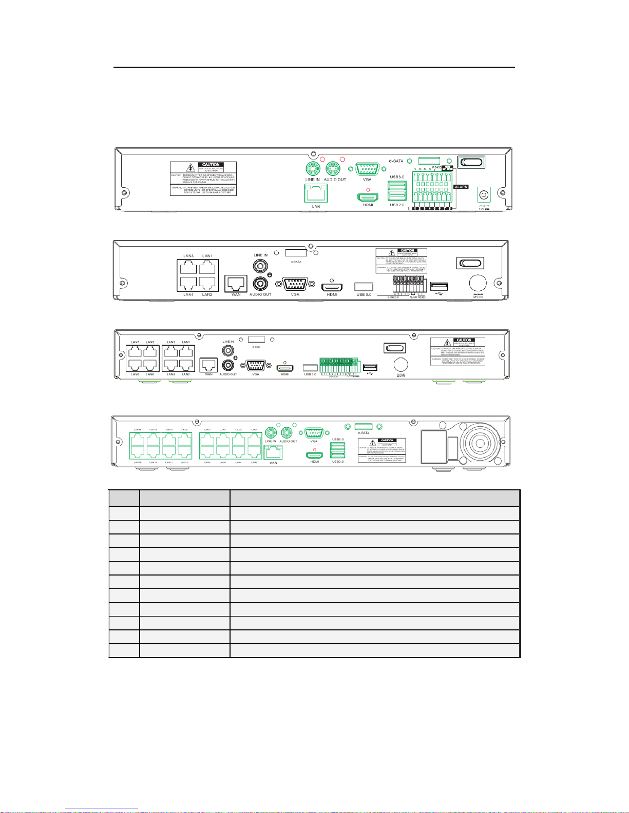
1.1 Rear Panel
NVR Rear Panel (For reference only)
Item Physical Port Connection Method
1 PowerSwitch
Startup and shutdown
2 PowerPort
Connect the attached power supply
3 USB Port
Connect USB devices, such as USB mouse and USB flash disk.
4 Sensor/Alarm
Connect to sensor or alarming device
5 HDMI Port
HDMI high definition port
6 VGA Port
Connect to VGA monitor, such as PC monitor
7 LINE IN
Intercom voice input
8 AUDIO OUTPUT
Audio signal output, RCA interface
9 WAN Port
Network input interface of the router/Connect to IP camera.
10 LAN Port
LAN network interface, support POE, can supply power to the camera.
11 E-SATA
Optional. Connect to e-SATA HDD for recording & backup
Page 7

USER MANUAL
7
1.2 Remote Controller (For reference only)
Item Key title Key function
1 1-8 Channel select 1-8; Numeric key
2
9、0
Numeric key
3 ALL Multiple display mode
4 Menu Enter into Main menu/Exit
5 Mute Mute On/off
6
Submenu
Go to submenu
7 ▲ Up arrow key, volume increase
8 SEL Select key/Edit key
9
◄/
Left/Right key; Decrease/increase parameter value of control bar.
10 ▼ Down arrow key, Volume decrease
11 Rewind key
12 Forward key
13 Enter into record search menu / Play key
14 ● Record key
15 ■ Stop manual record; stop playing
16 Pause/Sequence key
Table 1-3
1
2
4
6
7
8
9
10
12
13
15
14
3
5
9
11
16
Page 8

USER MANUAL
8
Chapter 2 NVR Connection
2.1 HDD Installation
Caution: Please do not take out hard drive when NVR is running!
HDD Installation:
(1) Cut power firstly, and then remove screws on both sides and rear panel and open NVR
upper cover.
(2) Connect HDD data cable and power cable to the main board. Install the HDD and fix it
on the bracket and then connect the HDD power cable and data cable.
(3) Put the upper cover back carefully
Note: If user requires higher performance HDD, it is strongly recommended to use hard
drive for security.
2.2 IP Camera and Monitor Connection
Transmit signals of IP camera to NVR by the network cable and connect VGA port
and HDMI port for output (Refer to section 2.2 Rear Panel). Refer to Chapter 6 System
Connection Diagram.
2.3 Power Supply Connection
Please use attached power adapter to connect NVR. Before power on, make sure
network port is well connected.
Page 9

USER MANUAL
9
Chapter 3 NVR Common Operations
3.1UsingtheSuppliedMouse
Left Button of Mouse Right Button of Mouse
Click once to choose an item in the menus and confirm
your selection.
Click once to open the
pop-up menu on the Live
Viewing screen and to exit
from the menus.
Click once upon a channel on Live Viewing screen to
open Camera Quick Toolbar
Double-click on the channel on the exit from the
menus. Live Viewing screen to view the channel in full
screen mode. Double-click again to exit the full screen
mode.
Click and hold to drag an area on motion mode or
adjust the values of sliders and scales on menu mode.
3.2UsingtheVirtualKeyboard
You will see the virtual keyboard automatically on the screen anytime you need to enter
data
0
Click to delete a character
Click to enter the text
Click to toggle the keyboard to upper
case and more punctuation
Page 10

USER MANUAL
10
3.3 Password & Locking the Screen Operation
When you run the DVR for the first time, you are required to set your password
immediately in order to protect your privacy. Please be sure to record your username and
password and save them in a secure place. If you forget your password, you will be
unable to login the system, please contact your reseller to reset the password. If you
forget your password, you will be unable to login the system. You can click
on the login interface, access to super-password through the mailbox.
If you don’t set the mailbox, please contact your reseller to reset the password. You would
need to tell the system date & your NVR’s MAC address. The MAC address can be check
by clicking
icon in the pop-up menu.
The screen will be locked to protect unauthorized OSD operation while the NVR is not in
menu operation for a while. If necessary, you can also lock the screen operation manually.
To do so, right-click on the Live Viewing screen to make the Pop-up menu bar visible, and
then click the Lock icon
.
Page 11

USER MANUAL
11
Chapter 4 NVR Boot up
4.1 Startup Wizard
After NVR startup is completed, the startup wizard will be displayed. If you do not
want to make any setting, you may click “Don't show this window next time” to cancel.
Wizard setting menu includes Startup Wizard, Network, IPC setup, Record Schedule
and HDD Management.
1) Startup Wizard
2) HDD Management
IftheHDDisinstalledintheNVRforthefirsttime,itwillbeneededtobeformat.SelecttheHDD
which you want to format, and then click “Format HDD” button to format the HDD.
Overwrite: Use this option to overwrite the old recordings on the HDD when the HDD is full. For example,
if you choose the option 7 days then only the last 7 days recordings are kept on the HDD. To prevent
overwriting any old recordings, select Disable. If you have disabled this function, please check the HDD
status regularly, to make sure the HDD is not full.
Page 12
USER MANUAL
12
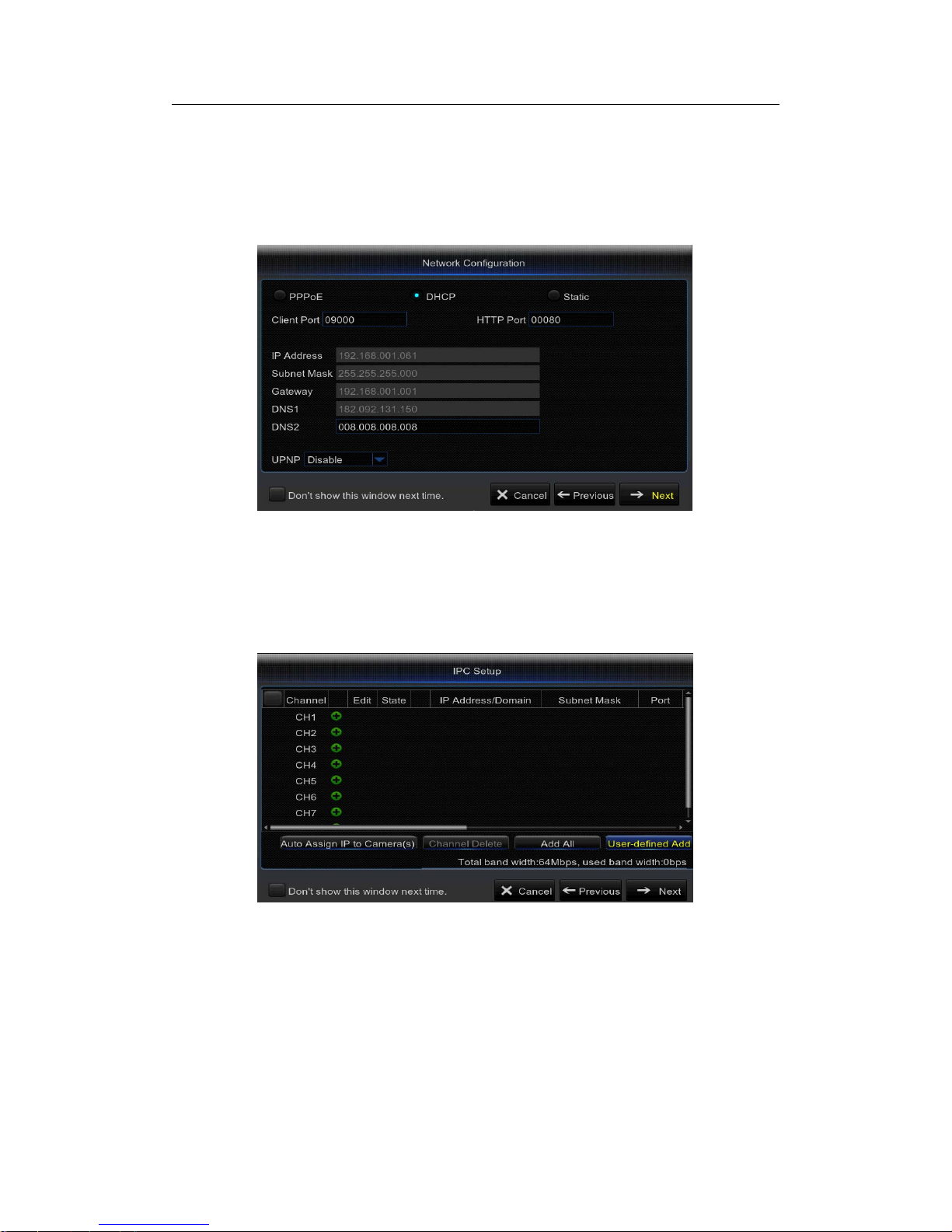
3) Network
This menu allows you to configure network parameters, such as PPPoE, DHCP, and
Static. The most common types are DHCP or Static. Most probably your network type is
DHCP, unless the network is manually addressed (usually called- Static). If you need an
authentication user name and password to the Internet, then choose PPPoE.
4) IPC Setup
This menu allows you to add and modify IP cameras configurations. For more details,
please check 5.2.1 IP Camera.
Page 13
USER MANUAL
13
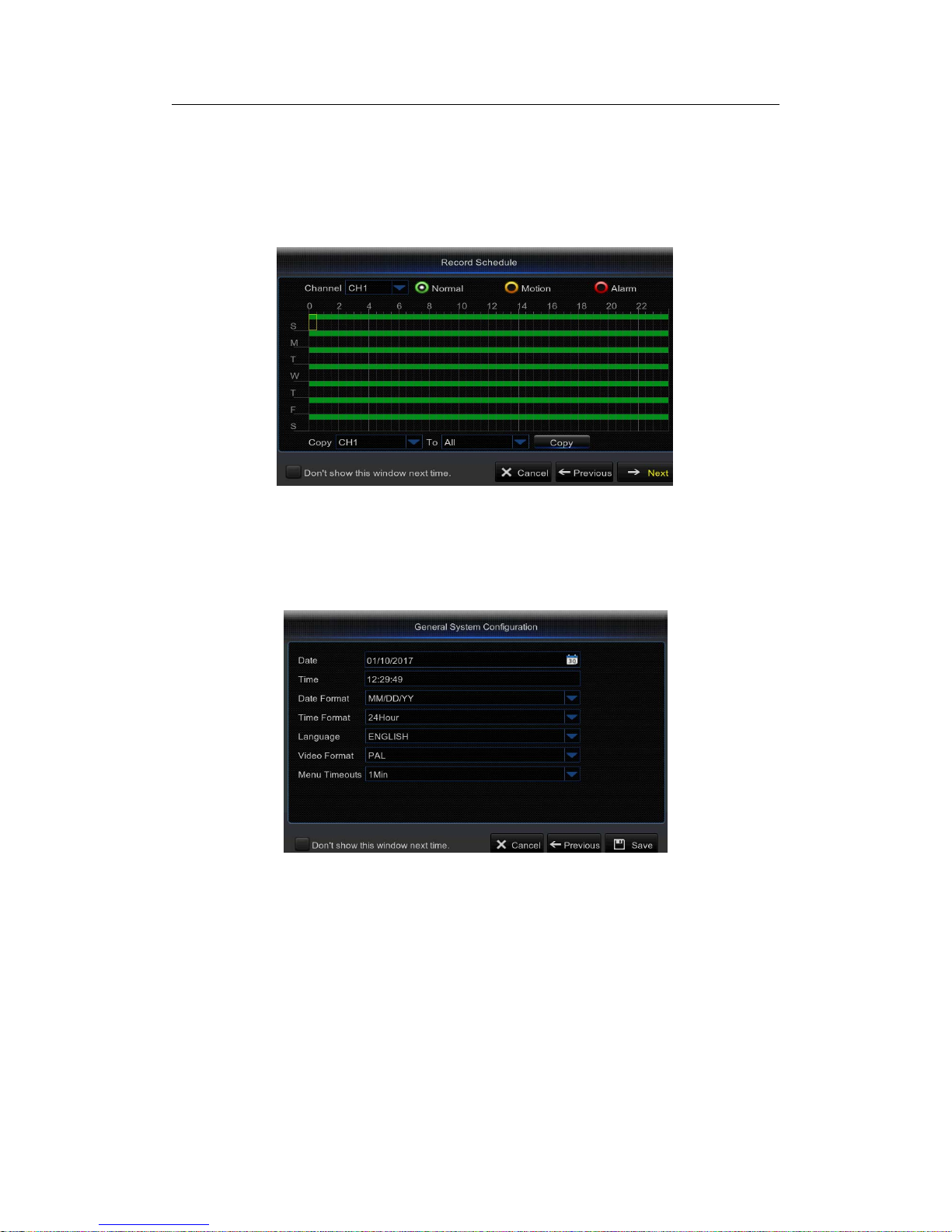
5) Record Schedule: This menu allows you to specify when the NVR records video and
define the recording mode for each channel. The recording schedule lets you set up a
schedule like, daily and hourly by Normal (continuous) recording, Motion recording, and
Alarm recording. To set the recording mode, click first on the mode radio button (Normal,
Motion, or Alarm), then drag the cursor to mark the slots.
6) General System Configuration: This menu allows you to configure the general
parameters of the system, such as Date, Time, Date Format, Time Format, Language,
Menu Timeouts.
Page 14
USER MANUAL
14
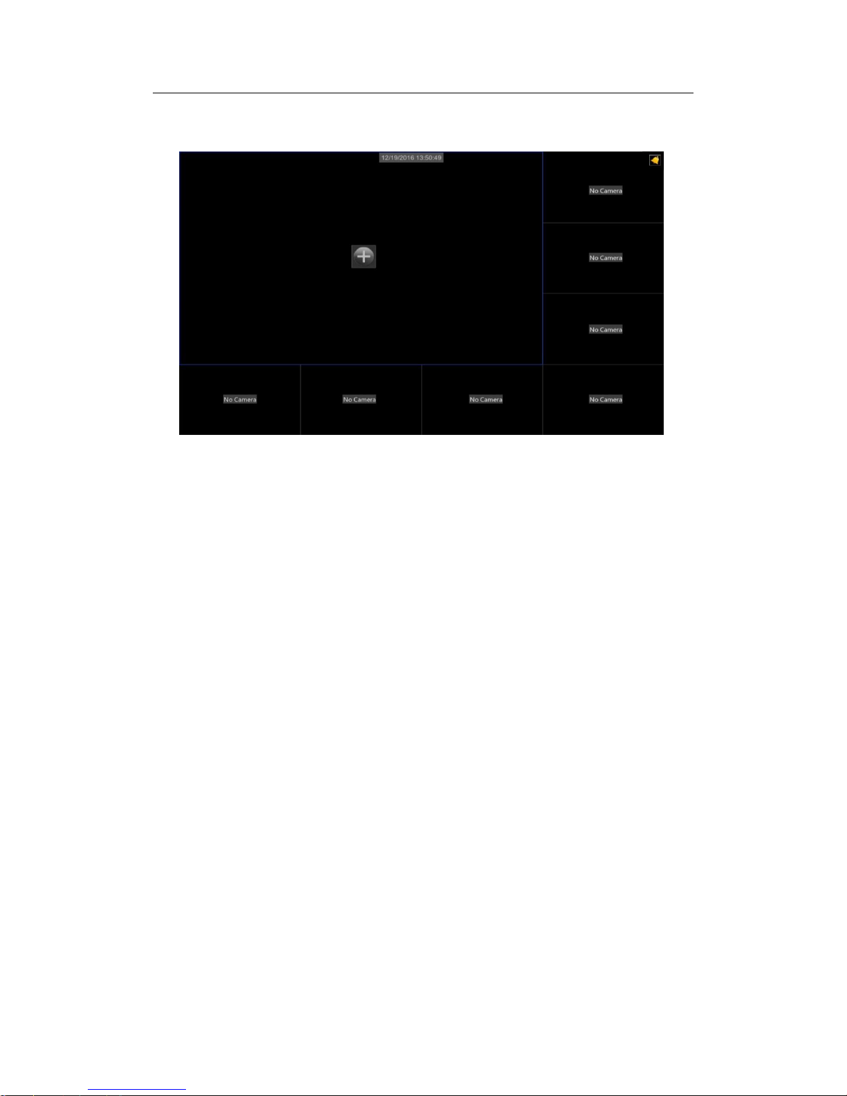
4.2 Main Interface
Note: When internal HDD is not connected to NVR or the HDD is not formatted, first
channel of the live screen and accompany buzzer alarm. If you want to close the buzzer
alarm, please enter into [AdvancedEvents] to set HDD loss, HDD space not enough and
alarm output to “off”.
Page 15

USER MANUAL
15
Chapter 5 NVR Menu
Popup Menu
Afterfinishing system initialization, click right key of mouse on preview interface o
r
slide the mouse to the bottom ofscreen to enterinto Pop-up Menu. Now you could
perform parameter setting and operate on Main Menu, Multi-screen (Quad, Nine), More
Layout, Stream switch, Preview Policy, Start SEQ, Mute, Playback, Info.
The options in the pop-up menu may be varied slightly acc ording to different
paramete
r
settings. The options in the menu will be explained in detail in the following
chapters.
Status Icons
This indicates that the NVR is currently recording.
ThemotioniconinGreenindicatesthattheNVRisdetectingmotionfromthecamera
but not recording.
This icon appears when the camera has detected motion and triggers recording.
The I/O alarm icon in Green indicates that the external sensor device is triggered but
not recording.
The I/O alarm icon in Red indicates that the external sensor device is triggered for
recording.
The Intelligent icon in Green indicates that the NVR is detecting Intelligent from the
camera but not recording.
Page 16

USER MANUAL
16
This icon appears when the camera has detected Intelligent and triggers recording.
The HDD icon indicates that the NVR cannot detect a HDD or the HDD is not formatted.
VIDEO LOSS: Connection to the camera has been lost.
Off-line: The added IP camera is offline or disconnected.
No Camera: IP Camera has not been connected to the NVR.
No HDD: HDD is not installed.
Pop-up Menu Bar
Click to open the Main Menu
Click to lock/unlock the screen operation
Click to switch to different camera views
Click to view more layout options
Click to switch all IP channels to mainstream or substream (for live view
resolution)
Click to switch among real‐time, balanced, or smooth view. The view effect modes
influence only the displayed video quality by bit rate and frame rate but do not influence
the recording quality.
Click to start viewing channels in a sequence.
Click to adjust the volume
Click to playback videos
Click to view system information
Page 17

USER MANUAL
17
Camera Quick Toolbar
Click to switch all IP channels to mainstream or substream (for live view
resolution)
Click to start recording the channel manually.
Click to playback the recent 5 minutes recording.
Click to zoom in the channel.
Click to adjust the channel color settings.
Click to enter PTZ control panel.
Page 18

USER MANUAL
18
Main Menu Guide
IP Camera
Live
Output
Image Control
PrivacyZone
Record
RecordSchedule
Mainstream
Substream
Mobilestream
Network
Switch
Email
Email Schedule
DDNS
RSTP
Motion
Alarm
Display
Shutdown
Main Menu
Advanced
System
Schedule
PID
SOD
LCD
Intelligent
Events
Maintain
Log
Info
Record Info
Channel Info
Info
General
DST
NTP
Users
General
Device
PTZ
HDD
Record Search
Events
Genera
l
Paramete
r
Alarm
Record
Network
PTZLinkage
FTP
Page 19

USER MANUAL
19
5.1 Overview
In Main Menu mode, you can make settings for Parameter, Record Search, Device,
System, Advanced,andShutdown.
Alarm – To set the motion detection function and/or I/O alarm function
Network - To configure the NVR’s access parameters to the network, configure email
settings, DDNS parameters, etc.
Record – To configure the recording options and set the recording schedule
Display – To configure how many channels are displayed on the Live Viewing screen,
for example color setup, video output resolution, privacy areas, etc.
Record Search – T o search for recordings, events, and captured images
Device – HDD Management, set the PTZ configuration parameters.
System - To modify general NVR settings, such as date and time, User management,
view system info, etc.
Advanced – Advanced settings, for example load default, Firmware update, etc.
Shutdown - To shut down or reboot the NVR
Copy (Parameters) To - Click to copy the current settings to all channels or one specific
channel.
Default - To restore the default settings
Save - Click to save the modifications
Cancel - Click to discard the modifications.
NOTE :After making modifications to the channel status, click Save to save the changes.
You are prompted to confirm the modifications. Click OK to confirm.
Page 20

USER MANUAL
20
5.2 Display
5.2.1 IP Camera
This NVR supports to connect IP camera inputs. In this menu, you can add, edit or delete
the IP cameras.
Auto Assign IP to Camera(s): Click to reassign an IP address to the IP camera that is
already connected to the NVR.
Add All: Click to add local ONVIF cameras (NVR and IP cameras are connected to the
same router). To complete the connection, enter user name and password of the IP
cameras, and click OK.
User-defined Add: Click to add remote ONVIF cameras over the Internet.
Enter the connection parameters of the IP camera: IP Address/Domain, Port, Protocol,
User Name,andPassword. Then click Add.
Page 21

USER MANUAL
21
With the Protocol Manage button, you can edit your own RTSP protocol to connect to IP
cameras.
In the Added IP Camera List, you can view the IP Camera Channel title, Delete IP
Camera, Edit.
IP Camera, Check the connection State,viewtheIP address/Domain / Subnet Mask /
Port,viewtheManufacturer of the added IP cameras, view the Device Type,checkthe
Protocol, MAC Address & Software version of IP cameras.
Page 22

USER MANUAL
22
5.2.2 Live
This menu allows you to configure channel parameters.
Channel: Select the channel you want to modify.
Channel Name: Enter the name of the channel.
Show Name: Enable to display the channel name on the live screen.
Record Time: Disable if you do not want to see the recording time on the channel.
Date Format:Set date format such as m/d/y, y/m/d or d/m/y.
Time Format: 12 hour or 24 hour.
Refresh Rate:60Hzor50Hz.
OSD Position: Click Setup to determine where you want the channel name and current date to
be displayed when you are viewing the channel. Drag the channel name box and the date/time
box to the desired location on the channel view.
Color: Click Setup to configure video color settings.
HUE: Changes the color mix of the image.
BRIGHT: Defines how bright the image appears on the display.
CONTRAST: Increases the difference between the darkest black and the whitest white in the
image. Modify the contrast if the sections of the image look “grey out”.
SATURATION: Alters how much color is displayed in the image. The higher the saturation, the
brighter and vivid colors will appear to be. Setting this parameter too high can degrade the
image quality.
Page 23

USER MANUAL
23
5.2.3 Output
This menu allows you to configure video output parameters.
Video Output: This is the monitor t hat you use for live view display.
Sequence Mode: Choose your favorite layout from the drop-down menu for viewing
channelsinasequenceonliveview.
SEQ Time: Set how long you want the live view from a channel to be displayed in a
sequence.
VGA/HDMI Resolution: Select the highest resolution your monitor/TV supports. The
higher the resolution, the more details you will see on your images. The NVR will restart
after you change the resolution.
5.2.4 Image Control
This menu allows you to configure the camera settings. Some IP cameras may not
support this feature and the IP camera settings cannot also be changed using the NVR.
Page 24

USER MANUAL
24
Channel: Select the channel you want to modify.
IR-CUT Mode: Select the desired built-in filter switch-over mode to ensure the camera
works properly both in the daylight and night.
IR-CUT Delay: Set the IR-CUT switching time delay.
Lens Flip/Angle Flip: Check to enable automatic lens flip and/or angle flip.
Angle Trad: Set the flip angle.
Back Light: Enable this feature to compensate the darkness of the subject when shooting
against bright light sources. For example, sunlight.
BLC Level: Set the backlight compensation level.
3D Noise Reduction: Enable this feature to digitally minimize video noise and extend the
NVR storage.
Level: Set the noise reduction level.
WDR (Wide Dynamic Range): Enable to allow automatically adjust the brightness and
contrast of the video when shooting in the darkness with bright light sources.
Level:SettheWDRlevel.
AGC (Automatic Gain Control): Configure when shooting in changing lightning
environments. The video image is brightened in dark areas.
White Balance: Choose the white balance level between Auto (automatic adjustment),
Manual (manual adjustment of red and blue gain), indoor (optimized according to the
indoor environment).
Red/Green/Blue: Adjust the red/green/blue value.
Shutter: Set the shutter mode.
Time Exposure: Choose the exposure time of the camera.
Defog Mode: Use in foggy environments to improve the video quality.
Level: Set the defog level.
Page 25

USER MANUAL
25
5.2.5 Privacy Zone
This menu allows you to create Privacy Zone(s) if you want to partially cover up part of the
image.
You can create up to four privacy zones in any size and location on the channel view.
These zone(s) appear as “red box rectangle areas”. Just click inside the default red-lined
rectangle and drag it where you want to create a privacy zone.
Select the Channel where you want to set privacy zone(s), then Enable Mask Area.
Decide how many privacy areas you want to set and check the area(s) in Area Setup,and
click Setup to open the channel in full screen mode and start marking the privacy zones.
Depending on the number of areas you have chosen in Area Setup,youwillseeareas
covered with black rectangles on the channel view. When you have finished marking the
areas, right-click to return to the Main Menu.
Page 26

USER MANUAL
26
5.3 Record
5.3.1 Record
This menu allows you to configure the channel recording parameters.
Channel: Select the channel to set its recording parameters.
Record Switch: Enable in order to allow the video to be recorded to the HDD.
Stream Mode: Choose the recording resolution. The available options are Mainstream
and Dualstream.
PreRecord Record: If this option is enabled, the NVR starts recording a few seconds
before an event occurs. Use this option if your primary recording type is motion based.
Note: The recorder supports Dualstream recording.
Page 27

USER MANUAL
27
5.3.2 Record Schedule
This menu allows you to specify when the NVR records video and define the recording mode for
each channel. The recording schedule lets you set up a schedule like, daily and hourly by
normal (continuous) recording, motion recording, and alarm recording. To set the recording
mode, click first on the mode radio button (Normal, Motion, or Alarm), then drag the cursor to
mark the slots. The recording schedule is valid only for one channel. If you want to use the
same recording schedule for other channels, use Copy To function.
Channel: Select the channel to set its recording parameters.
Normal: When the time slot is marked green, this indicates the channel performs normal
recording for that time slot.
Motion: When the time slot is marked yellow, this indicates the channel records only when
a motion is detected during that time slot.
Alarm: When the time slot is marked red, this indicates the channel records only when the
sensor is triggered during that time slot.
Note:
1. In the Record menu and Record Search menu, No Color stands for no record.
2. “Green” stands for normal record and “yellow” stands for motion record.
3. “Red” stands for alarm record.
4. No Record: A time slot marked black means that there is no recording scheduled for the
time slot.
5. To use the motion detection, you must enable and configure the motion settings for the
channel in Alarm menu. Please see 5.5.1 Motion
Page 28
USER MANUAL
28
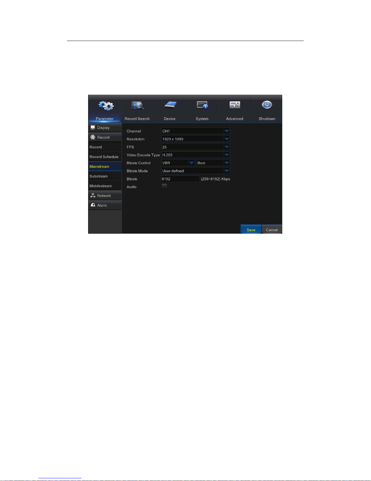
5.3.3 Mainstream
This menu allows you to configure the recorded video parameters. All the modifications
you apply to these settings will affect the recorded video saved into the HDD.
Channel: Select the channel to configure recording related information.
Resolution: This parameter defines how large the recorded image will be.
FPS: This parameter defines the number of frames per second the NVR will record.
Video Encode type: H.264 OR H.265.
Bitrate Control: Select the bitrate level based on the complexity of the scene. For a
simple scene, such as a gray wall is suitable constant bitrate (CBR). For more complex
scene, such as a busy street is suitable variable bitrate (VBR).
Bitrate Mode: If you want to set the bitrate by yourself, then choose User-defined mode. If
you want to select the predefined bitrate, choose Predefined mode.
Bitrate: This parameter corresponds to t he speed of data transfer that the NVR will use to
record video. Recordings that are encoded at higher bitrates will be of better quality.
Audio: Select this option if you want to record audio along with video and have a
microphone c onnected to the NVR or using a camera with audio capability.
Page 29

USER MANUAL
29
5.3.4 Substream
This menu allows you to configure the settings of a particular channel if the channel is
being viewed via remote access, for example Web Client.
Channel: Select the channel to configure recording related information.
Resolution: This parameter defines how large the recorded image will be.
FPS: This parameter defines the number of frames per second the NVR will record.
Video Encode type: H.264 OR H.265.
Bitrate Control: Select the bitrate level based on the complexity of the scene. For a
simple scene, such as a gray wall is suitable constant bitrate (CBR). For more complex
scene, such as a busy street is suitable variable bitrate (VBR).
Bitrate Mode: If you want to set the bitrate by yourself, then choose User-defined mode. If
you want to select the predefined bitrate, choose Predefined mode.
Bitrate: This parameter corresponds to t he speed of data transfer that the NVR will use to
record video. Recordings that are encoded at higher bitrates will be of better quality.
Audio: Select this option if you want to record audio along with video and have a
microphone c onnected to the NVR or using a camera with audio capability.
Page 30

USER MANUAL
30
5.3.5 Mobilestream
This menu allows you to configure the settings of a particular channel if the channel is
being viewed via mobile devices
Channel: Select the channel to configure recording related information.
Enable: Enable to allow to use mobile streaming on this channel
Resolution: This parameter defines how large the recorded image will be.
FPS: This parameter defines the number of frames per second the NVR will record.
Video Encode type: H.264 or H.265.
Bitrate Control: Select the bitrate level based on the complexity of the scene. For a
simple scene, such as a gray wall is suitable constant bitrate (CBR). For more complex
scene, such as a busy street is suitable variable bitrate (VBR).
Bitrate Mode: If you want to set the bitrate by yourself, then choose User-defined mode. If
you want to select the predefined bitrate, choose Predefined mode.
Bitrate: This parameter corresponds to t he speed of data transfer that the NVR will use to
record video. Recordings that are encoded at higher bitrates will be of better quality.
Audio: Select this option if you want to record audio along with video and have a
microphone c onnected to the NVR or using a camera with audio capability
Page 31
USER MANUAL
31
5.4 Network
This menu allows you to configure Network parameters, Switch, E-mail setup, DDNS,
RTSP & FTP.
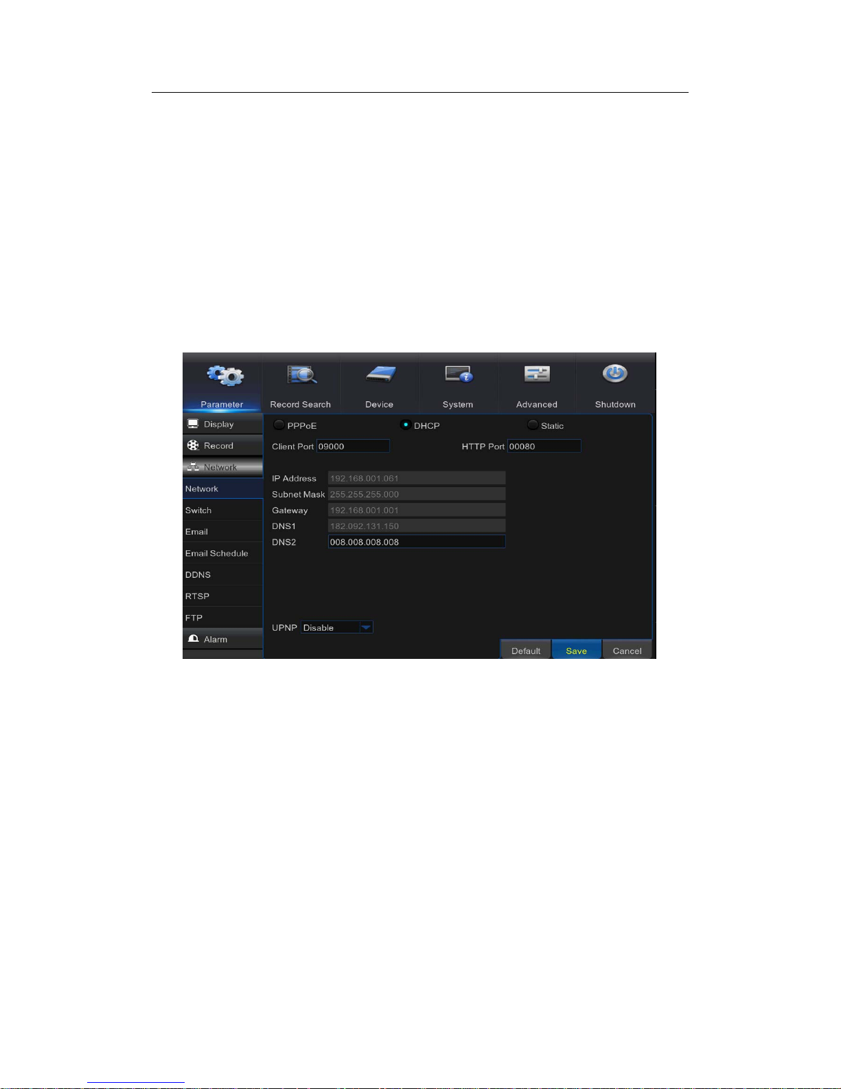
5.4.1 Network
This menu allows you to configure network parameters, such as PPPoE, DHCP, and
Static. The most common types are DHCP or Static. Most probably your network type is
DHCP, unless the network is manually addressed (usually called- Static). If you need an
authentication user name and password to the Internet, then choose PPPoE.
Network Type: Select the network type you are using.
PPPoE: This is an advanced protocol that allows the NVR to connect to the network more
directly via DSL modem.
DHCP: This is the network type when a device on your network (usually a router) assigns
automatically all the network parameters for your NVR.
Static: Requires all the network parameters to be filled in manually.
HTTP Port: This is the port that you will use to log in remotely to the NVR (e.g. using the
Web Client). If the default port 80 is already taken by other applications, please change it.
Client Port: This is the port that the NVR will use to send information through. If the
default port 9000 is already taken by other applications, please change it.
IP Address: The IP address identifies the NVR in the network. It consists of four groups of
numbers between 0 to 255, separated by periods. For example, “192.168.001.100”. You
need to enter the IP address manually only if your network type is Static.
Subnet Mask: Subnet mask is a network parameter which defines a range of IP
addresses that can be used in a network. If IP address is like a street where you live then
subnet mask is like a neighborhood. The subnet address also consists of four groups of
Page 32

USER MANUAL
32
numbers, separated by periods. For example, “255.255.000.000”. Alike IP address, you
need to enter the subnet mask manually only if your network type is Static.
Gateway: This address allows the NVR to access the Internet. The format of the Gateway
address is the same as the IP Address. For example, “192.168.001.001”. Alike IP address,
you need to enter the gateway address manually only if your network type is Static.
DNS1/DNS2: DNS1 is the primary DNS server and DNS2 is a backup DNS server .
Usually should be enough just to enter the DNS1 server address.
UPNP: If you want to log in remotely to the NVR using Web Client, you need to complete
the port forwarding. Enable this option if your router supports the UPnP. You need to
enable UPnP both, on NVR and router. In this case, you do not need to configure
manually port forwarding on your router. If your router does not support UPnP, make sure
the port forwarding is completed manually.
5.4.2 Switch
IP Address: The default IP address of the POE interface.
Subnet Mask: The default Subnet Mask of the POE interface.
Gateway: The default Gateway of the POE interface.
Switch Mode : Auto Mode, Manual Mode , When set to Auto Mode, the channel
automatically connects to the IPC on all POE interfaces of the NVR. The user cannot
delete or add the network IPC to the channel. When set to Manual Mode, the user can
delete or add the network IPC.
Page 33
USER MANUAL
33
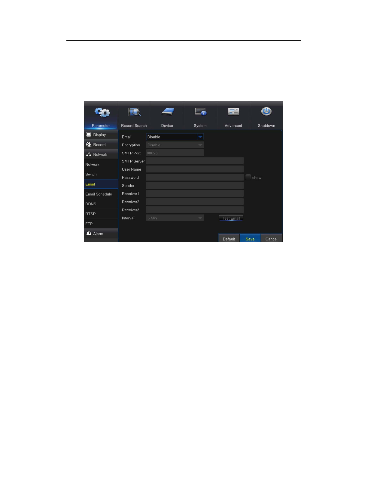
5.4.3 Email
This menu allows you to configure email settings. Please complete these settings if you
want to receive the system notifications on your email when a motion is detected, HDD
becomes full, HDD is in error state, or Video Loss occurs.
Email: Enable this feature.
Encryption: Enable if your email server requires the SSL or TLS verification. If you are
not sure, set to be Auto.
SMTP Port: Enter the SMTP port of your email server.
SMTP Server: Enter the SMTP server address of your email.
User Name: Enter your email address.
Password: Enter the password of your email.
Receiver 1~3: Enter the email address where you want to receive the event notifications
from the NVR.
Interval: Configure the length of the time interval between the notification emails from the
NVR. To make sure all settings are correct, click Test Email. The system sends an
automated email message to your inbox. If you received the test email, it means the
configuration parameters are correct.
Page 34

USER MANUAL
34
5.4.4 Email Schedule
The color codes on email schedule have the following meanings:
Green: Slot for Motion.
Yellow: Slot for I/O Alarm.
Red: Slot for Exception (HDD full, HDD error , or Video Loss).
Sky blue: stands for Intelligent (PID, LCD or SOD).
5.4.5 DDNS
This menu allows you to configure DDNS settings. The DDNS provides a static address to
simplify remote connection to your NVR. To use the DDNS, you first need to open an
account on the DDNS service provider’s web page.
Page 35

USER MANUAL
35
DDNS: Enable the DDNS service.
Server: Select the preferred DDNS server (DDNS_3322, DYNDNS, NO_IP, CHANGEIP,
and DNSEXIT).
Domain: Enter the domain name you created on the DDNS service provider’s web page.
This will be the address you type in the URL box when you want to connect remotely to
the NVR via PC. Fox example: dvr.no-ip.org.
User/Password: Enter the user name and password you obtained when creating an
account on the DDNS service provider’s web page. After all parameters are entered, click
Test DDNS to test the DDNS settings.
5.4.6 RTSP
The NVR can be remotely viewed via RTSP protocol.
RTSP Enable: Enable/Disable.
Verify: Enable/Disable.
RTSP Port: Default is 554, if the default port 554 is already taken by other applications,
please change it.
Page 36

USER MANUAL
36
Instruction: rtsp://IP:Port/ipA/B.
A: 01(ip1), 02(ip2)….8(ip16)
B: 0(main stream), 1(sub stream)
For example, the NVR IP address is 192.168.1.61, and you want to view CH1 with
mainstream, then the RTSP address will be: rtsp://192.168.1.61:554/ip1/0
Note: RTSP user name and password is same with NVR user name, password and
permissions. Follow the instruction to input IP and port to preview video.
5.4.7 FTP
This menu allows you to enable FTP function to view and load captured snapshots from
NVR to your storage device over FTP.
Page 37

USER MANUAL
37
FTP Enable: Enable the feature in NVR.
Server IP: Enter your FTP server IP address or domain name.
Port: Enter the FTP port for file exchanges.
User Name/ Password: Enter your FTP server user name and password.
Directory Name: Enter the default directory name for the FTP file exchanges.
Test FTP: Click to test the FTP settings.
5.5 Alarm
In these sections, you can configure the Motion Detection, I/O Alarm & PTZ Linkage.
5.5.1 Motion
This menu allows you to configure motion parameters. The motion detection is pretty
straight forward; the NVR simply compares one frame to another. A sufficient amount of
difference is interpreted as motion. When the motion is detected, the system can be set to
automatically initiate recording. In this menu you can select the channels where you want
the motion detection recording to take place.
If you set the motion detection at a high sensitivity level (“8” is the most sensitive) then the
frequency of false alarm events increases. If the sensitivity level is too low (“1” is the least
sensitive), you might increase the risk that a significant motion event will not trigger the
motion detection to record.
Channel: Select the channel you want to set the motion detection.
Enable: Enable or disable the function.
Page 38

USER MANUAL
38
Buzzer: The NVR can use its internal buzzer to emit an alarm tone. You can set the
buzzer duration in seconds when the motion is detected.
Sensitivity: Set the sensitivity level.
Area: To setup motion area, click Setup. By default, the whole screen is marked for motion
detection (red blocks). If you want to disable the motion detection on an area, you need to
click the grid cursor and then drag the mouse to highlight the scope to unmark the area
(transparent block). After setting is completed, right click the mouse button to return and
click Save to make the area setup effective.
Post Recording: You can set how long after an event occurs that the NVR will continue to
record. The recommended recording length is 30 seconds but it can be set higher up to 5
minutes.
Alarm Out: Optional function. If your NVR support to connect to external alarm device,
youcansettoemitanalarmtone.
Latch Time: To configure the external alarm time when motion is detected.
Show Message: Check the box to display “M” icon on the screen when the motion is
detected.
Send Email: You can let the NVR to send you an auto-email when the motion is detected.
Full Screen: If this function is enabled and a motion is detected in a channel, you will see
that channel in full screen.
Record Channels: Here you can select which channels you want to include to t he motion
detection. If the motion is detected, the record ing will start immediately on those channels.
Page 39

USER MANUAL
39
5.5.2 Alarm
This is an optional function. If the NVR you purchased doesn’t support connect external
sensor I/O alarm devices, you will not find this section in your NVR OSD menu.
Alarm In: User may set four groups of alarm inputs
Alarm Type: There are 3 types for your choice: Normally-Open, Normally-Close, and OFF.
Choose the one to match your sensor type, or Choose OFF to close t he sensor trigger
function.
Latch Time: you can set how long the buzzer will sound when external sensor is triggered
(10s, 20s, 40s, and 60s).
Buzzer: The NVR can use its internal buzzer to emit an alarm tone. You can set the
buzzer duration in seconds when a sensor is triggered.
Post Recording: You can set how long alarm record will last when alarm ends (30s,
1minutes, 2minutes, 5minutes).
Alarm out: Tick to enable external alarm device to emit an alarm tone when a sensor is
triggered.
Show Message: Display the alarm messages on the screen when sensor is triggered.
Send Email: Set to send email to specified email when sensor is triggered.
Full Screen: When sensor is triggered, the corresponding channel will be switched to the
full screen mode.
Record Channels: Select which channels you want to record when sensor is triggered.
Page 40

USER MANUAL
40
5.5.3 PTZLinkage
If you had connected the PTZ cameras, you can set the linkage between PTZ cameras
and Motion Alarm and/o
r
external I/O sensoralarm. With the linkage function, you can
turn you
r
PTZ cameras focus to the preset point when a motion or I/O alarm happens.
Channel: Select the channel to set.
Switch: Enable or disable the PTZ linkage function.
Alarm Type: Choose what kind of alarm will trigger the PTZ linkage function.
PTZ: Associates the PTZ camera with preset points. View preset point at 5.7.3.2 PTZ
control
Page 41

USER MANUAL
41
5.6 Record Search
This section allows you to search and playback the recorded videos based on recording
type, channel, date and time parameters. You can also view and backup events and
captured images.
5.6.1 General
1) Select the channel & the recording type (All / Normal / Alarm (including preset point &
IO) /Motion / IO / Manual).
2) Determine the recording date.
3) Click Search.
4) Select the recording from the table.
NOTE: Dates marked with orange triangles have video recordings.
5) Select the channels you want to playback.
6) Modify the start time and end time if necessary and then click Play.
Enter the playback interface, to view 5.7.3 Playback Video Recordings.
5.6.2 Events
This section is used to check the recording file lists and make backup.
1) Select the recording Date & Time.
2) Select the Channel and Type (All / Normal / Alarm (including Motion & IO) / Motion /
IO).
3) Click Search.
4) If you want to make backup for all recording files you had searched, click Quick
Page 42

USER MANUAL
42
Backup.
5) If you want to make backup for individual files, select the recording list(s) from the table.
6) If you want to move to other page, click << or >> to move to previous or next page. Or
input the number of page, and then click
to jump to the page.
7) After selecting the files, click Backup to start the backup. There are 3 kinds file formats
for your backup files: original RF, AVI and mp4. The total size of the backup files will be
displayed, please make sure not to exceed the available capacity of your USB flash
device.
Note: Please make sure you have inserted your USB flash device to the NVR USB port
before you want to make backup.
Page 43

USER MANUAL
43
5.6.3 Playback Video Recordings
1. Recording Calendar: Dates marked with orange triangles have recordings.
2. Playback Type: Select the playback type among General, Events, Picture &
Sub-periods
3. Channels: Check the channels to playback.
4. Playback Control Bar.
Full Screen
Fast Forward, x2, x4, x8 and x16
Fast Rewind: x2,
x4, x8 and x16
Digital Zoom: Click to zoom in
Slow Play: 1/2, 1/4
and 1/8 speed
Trim Video: view 5.7.4.2 Trim Video
Play & Pause
Volume Control: Slide the slider
bar to increase or decrease
volume.
Click to mute audio.
Pause, Play
frame by frame
Stop
Page 44
USER MANUAL
44
5. Time Bar: The color indicates the video recording type:
- Motion recording (Yellow)
- Normal recording (Green)
- I/O sensor recording (Blue)
- Alarm recording (Red)
- Intelligent recording (Sky blue)
6. Time Frame: Select Playback timeline. View 5.7.4.3 Time Frame
8. Recording Type Indicator: Motion, Smart, Normal, IO & Alarm.
9. Recording Playback Screen: Video recordings from selected channels.
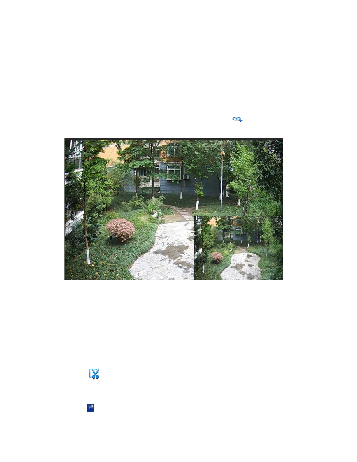
10. zoom in/out:When it is under single channel playback, the
icon will appear in
the Play Control bar. Click the icon to zoom in certain area of the playback screen and
right click mouse to return the Playback page.
5.6.3.1 Trim Video
Use this function if you need to backup just a certain section of the video recording.
1) Connect a USB flash drive to the NVR.
2) Double-click on the channel (to display in full screen during video playback) that you
wish to backup.
3) Clic k on the Time Bar to mark the beginning of the video footage you wish to backup.
4) Click
to start selecting the footage.
5) Click on the Time Bar to mark the end of the video footage you wish to backup.
Themarkedupareaisnowdisplayedwithintheredarrows.
6) Click to save the footage.
Page 45

USER MANUAL
45
7) Select the channel to be backed up.
8) A video type selection message appears. Select the file format and click
Page 46

USER MANUAL
46
5.6.3.2 Time Frame
During video playback, the time bar is displayed in 24 Hours (00:00~24:00) by default.
You can shorten the time bar to be displayed in 2 Hours, 1 Hour or 30 Minutes in order to
make an accurate position to the time bar.
Page 47

USER MANUAL
47
5.6.3.3 Sub-periods Playback
This function will allow you to divide a recording video into average separate segments
and play together in the same screen.
1) In the video playback interface, choose Sub-periods from Playback Type section.
2) Select a channel you want to play.
3) Choose the Split Screens. If you have a 4 Channel NVR, the max. Split screens will be
4. And
8 for 8 Channel NVR as well 16 for 16 Channel NVR.
For example, if the video you want to play is 60 minutes in length, and the split screen is 4,
the video will be divided in to 4 segments, and each segment will be 15 minutes in length.
All the 4 segments will be played in the same screen.
Page 48

USER MANUAL
48
5.6.4 Play Backup Files
This section will help you to play the backup files.
1) Install the Video_Player software in the CD and run.
2) Copy the backup files to your computer.
3) Click “+” or “Open File” button to add files. It supports to play rf, avi, mp4, 264 & 265
files.
Page 49

USER MANUAL
49
Function Description:
Play: Click to play file
Pause: Click to pause.
Stop: Click to stop playback.
Frame Forward: step forward by frame
Slow
forward
: Click to play at
8x,4x,2x,1x,1/2,1/4,1/8,1/16
speed.
Fast
forward
: Click to play at
16x,8x,4x,2x,1x,1/2x,1/4x,1/8x
speed
Open file/Open Directory
Expand/pack up the list.
Screenshot: Save path: C:\Users\Administrator\VideoPlayer\picture
Cut: Save path: C:\Users\Administrator\VideoPlayer\video
Full screen display
Never on top
Always on top
On top during playing
Adjust volume
Window Division
1/4/9/16 channels optional.
Add folder or file.
Playback mode, Single, Order, Repeat one, Repeat ALL are optional
Delete all files in the list.
Search File
Language/Settings
Page 50

USER MANUAL
50
Basic Settings: Set on-top mode
Capture Settings: Set the path to save images
Page 51

USER MANUAL
51
5.7 Device
In this section, you can configure the i nternal HDD, PTZ setup.
5.7.1 HDD
Go to “Main Menu” → “Device” → “HDD” to enter into the interface.
When HDD is connected, the system will automatically detect if HDD is normal or
not; If HDD need to be formatted, status will be shown as “Not formatted”. Select the
HDD and format the HDD. If the system detects HDD is normal state, the HDD status
will be shown as “Normal”.
Page 52

USER MANUAL
52
No.: Number of HDD connected to system.
Type: Hard disk read and write types, divided into: read and write, redundant and
read-only.
Disk Group: Disk group number
Status: It shows the current status of HDD. It will be available only when HDD is
“Normal”.
Free/Total Space: Remaining or total space of HDD
Free Time: Remaining time for HDD recording according to currently set “Resolution”,
“Encoding Rate” and “Frame Rate” of image.
Auto-overwrite: When set to ENABLE, the NVR will overwrite the oldest files on the
hard drive if hard drive space is full. When set to DISABLE, the NVR will stop
recording if hard drive space is full. Overwrite time: 1 day, 3 days, 7 days, 14 days, 30
days and 90 days. It means the longest storage time of records in HDD. If the time is
over, the records will be deleted. For example, if the time is set as 3 hours and the
data in HDD include 12, 13, 14, 15, 16, 17, 18, 19 and 20 o’clock, then data 18, 19
and 20 will be saved and data 12, 13, 14, 15, 16 and 17 will be deleted.
Record On ESATA: Enable/disable record on esata.
Format HDD: Format HDD for the first use.
Note: 1. Recording can only be performed when HDD is in “Normal” state.
2. After the Record On ESATA is turned on, the estata backup will not be
available.Turn off Record On ESATA to turn on ESATA backup.
3. C
lick below Edit corresponding to disk serial number to be modified, and
modify the data and parameter accordingly .
Page 53

USER MANUAL
53
Tip: All hard disk disk group number are the default 1, one can only choose a hard disk to
set.
Disk Type: Read-write, read-only, and redundant.
To prevent important video data from being overwritten during cyclic recording, you can
protect the hard disk by setting it to "read-only" mode.The hard disk is set to "redundant",
can be achieved in the read and write disk for video at the same time, in the redundant
disk also redundant recording, to improve the reliability of the video.
5.7.2 Disk Group
This menu allows you to accord their actual situation, the video channel assigned to the
corresponding disk group. Make sure that each channel has at least one disk group
association. Otherwise, the recording will be abnormal when the channel is opened.
Page 54

USER MANUAL
54
5.7.3 PTZ
5.7.3.1 PTZ set
This menu allows you to configure the PTZ (Pan-Tilt-Zoom) settings for the dome camera.
Channel: Choose a channel where is connected a dome camera.
Signal Type
Digital: no parameter setting is required and no connecting the RS-485 control
cable.
Analog: need parameter setting is required and connecting the RS-485 control
cable.
Baudrate: The speed of the information sent from the NVR to the PTZ-capable camera.
Make sure it matches the compatibility level of your PTZ-capable camera.
DataBit / StopBit: The information between the NVR and PTZ-capable camera is sent in
individual packages. The DataBit indicates the number of bits sent, while the DataBit
indicates the end of the package and the beginning of the next (information) package. The
available parameters for DataBit are: 8, 7, 6, 5. the available parameters for the StopBit
are1or2.
Parity: For error check. See the documentation of your PTZ-capable camera, to configure
this setting.
Cruise: Enable to allow to use the Cruise mode. In order to use the Cruise mode, you
need to set a number of preset points.
Address: Set the command address of the PTZ system. Please be noted that each
PTZ-capable camera needs a unique address to function properly
Page 55
USER MANUAL
55
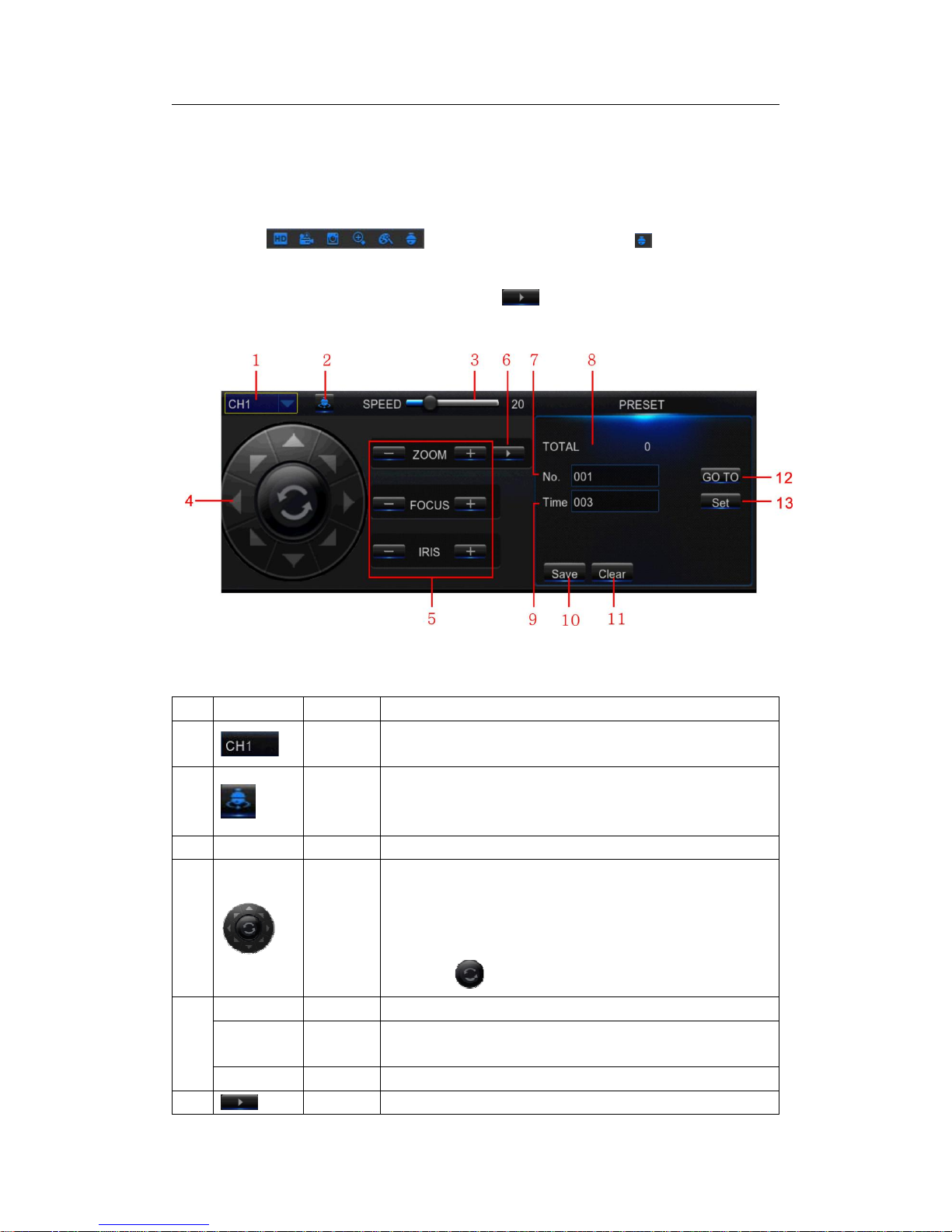
5.7.3.2 PTZ control
After finishing the PTZ setup, you can use the PTZ function to control your PTZ camera.
1) Left click your mouse upon a channel on Live Viewing screen to open Camera Quick
Toolbar
, and click the PTZ control icon .
2) PTZ control panel will be displayed. Click
to active PRESET points setup
page.
No. Icon Item Description
1
Channel Click to select the channel of the PTZ camera.
2
Cruise
Start / stop PTZ cruise by preset points. Make sure you
had enable the Cruise function for this channel in 5.8.3
PTZ Setup
3 Speed Speed Adjust the PTZ speed
4
Pointer
Panel
A) Click the direction arrow to select the direction of the
PTZ camera
B) Click up/down/left/right arrow to move cursor in UTC
OSD menu
C) Click
to switch to auto pan mode
5
- ZOOM + Zoom Click to zoom in/out.
-FOCUS
+
Focus Click to adjust the focus
- IRIS + Iris Click to adjust the iris setting
6
PRESET To display or hide the preset point panel
Page 56

USER MANUAL
56
7 No No. Number of preset point
8 Total Total Display the total number of preset points
9 Time Time
Set the time how long the camera will stay in the preset
point
10 Save Save Click to save the settings and preset points
11 Clear Clear Click to delete the selected preset point
12 GO_TO Go to
Enter the number of a specific preset point, click this
button to move your PTZ camera to the preset point
13 Set Set
Click to set a specific preset point on a PTZ camera.
You can add up to 255 preset points for the NVR.
However, the actual preset quantity varies depending on
the PTZ camera performance.
5.8 System
You are able to configure general parameters of the system, such as date and time, OSD
language, menu timeouts, DST, NTP, User Management, check system information &
system log here.
5.8.1 General
Date/Time: Enter the date and time manually.
NOTE: For date/time automation over the Internet, enable NTP.
Date Format: Set the date format here.
Page 57

USER MANUAL
57
Time Format: Set the time format here.
Language: Choose the OSD language.
Video Format: Choose the video format between NTSC and PAL. If the NVR’s picture is
flickering or has only black screen, it may be that the video format is not correct.
Menu Timeouts: Set the time out the NVR will exit the menus when they are not in use.
Show Wizard: Check if you want the Startup Wizard to reappear each time you start up
the NVR.
5.8.2 DST
DST stands for Daylight Savings Time.
DST: Enable if Daylight Saving Time (DST) is observed in your region.
Time Offset: Select the amount of time to offset for DST.
Daylight Saving Time: Choose to set the daylight saving time in weeks or in days.
Start Time/End Time: Set the start time and end time for daylight saving.
Page 58

USER MANUAL
58
5.8.3 NTP
NTP stands for Network Time Protocol. This feature allows you to synchronize the date
and time automatically on the NVR over Internet. Therefore the NVR needs to be
connected to the Internet.
NTP: Enable if you want the NVR to update the date and time automatically.
Server Address: Select the NTP (Network Time Protocol) server.
Time Zone: Select the Time Zone in your location.
Update Time: Click here to update the system date and time immediately.
Note: When NTP function is enabled, system will update the system time at 00:07:50
every day, or every time when the system is started up.
5.8.4 Users
This menu allows you to configure the userlogin information.
Page 59

USER MANUAL
59
Edit: To enable/disable the user account, modify the user name and password, click on
the user account you wish to edit, then click Edit.
Permission: To modify user access permissions, click on the user account you wish to
modify, and then click Permission. The user in Admin level has all permissions to the
system. After modify the permissions, click Save to save the modifications.
Page 60
USER MANUAL
60
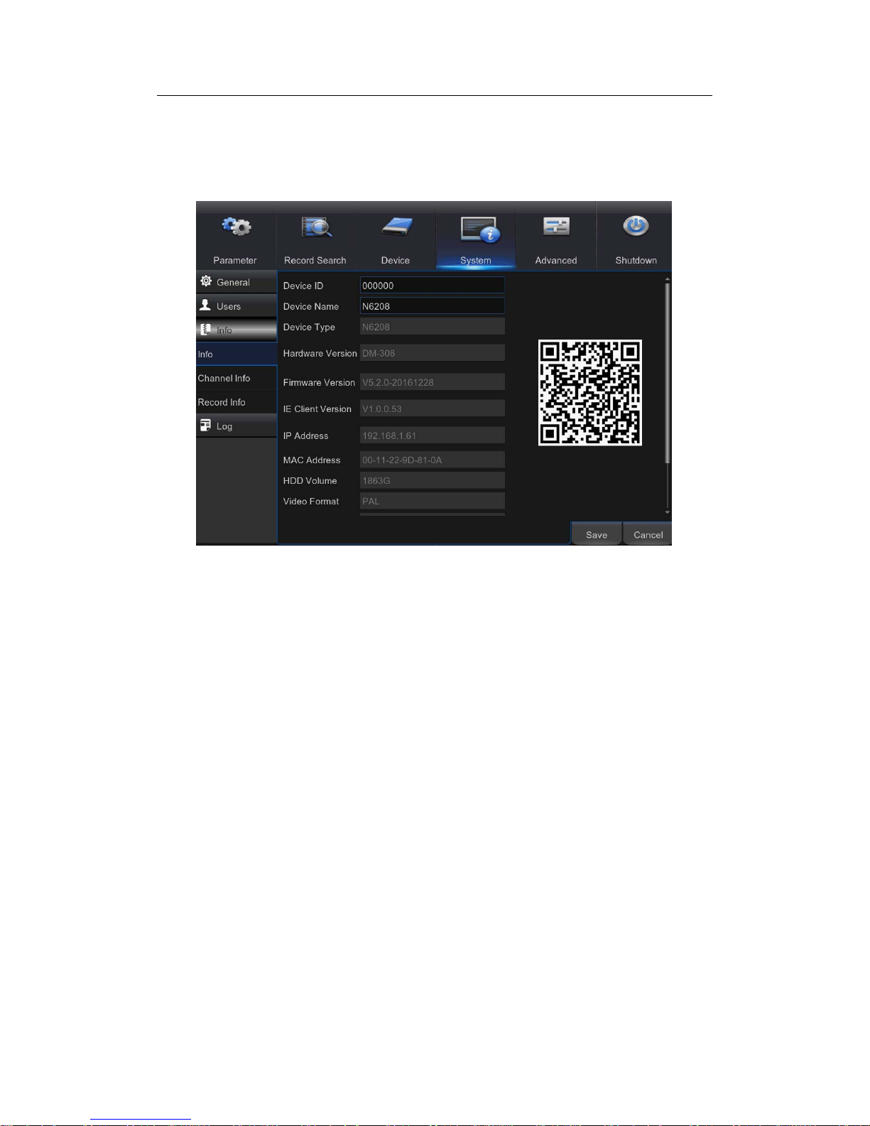
5.8.5 Info
This menu allows you to view the summary of the system, channel information & record
information.
Device ID: Enter the desired ID for your NVR. The device ID is used to identify the NVR,
and can only be composed of numbers, and cannot be the same with other IDs when
multiple NVRs are connected in the same network.
Device Name: Enter the desired name for your NVR. The name can include both letters
and numbers.
MAC Address: Display the MAC address of the NVR. When multiple NVRs are
connected to the same network, each NVR must have a unique MAC address to ensure
that the NVR can connect to the network.
Note: If your NVR support P2P function, you will find a QR code in the info page. You can
scan this QR cord with mobile app to remote access this NVR, view more on Chapter 7
Remote Access via Mobiel Devices.
Channel Info: To view the information summary on the channels.
Record Info: To view the recording information summary by channel, record state, stream
type, FPS, bitrate, and resolution.
Page 61
USER MANUAL
61
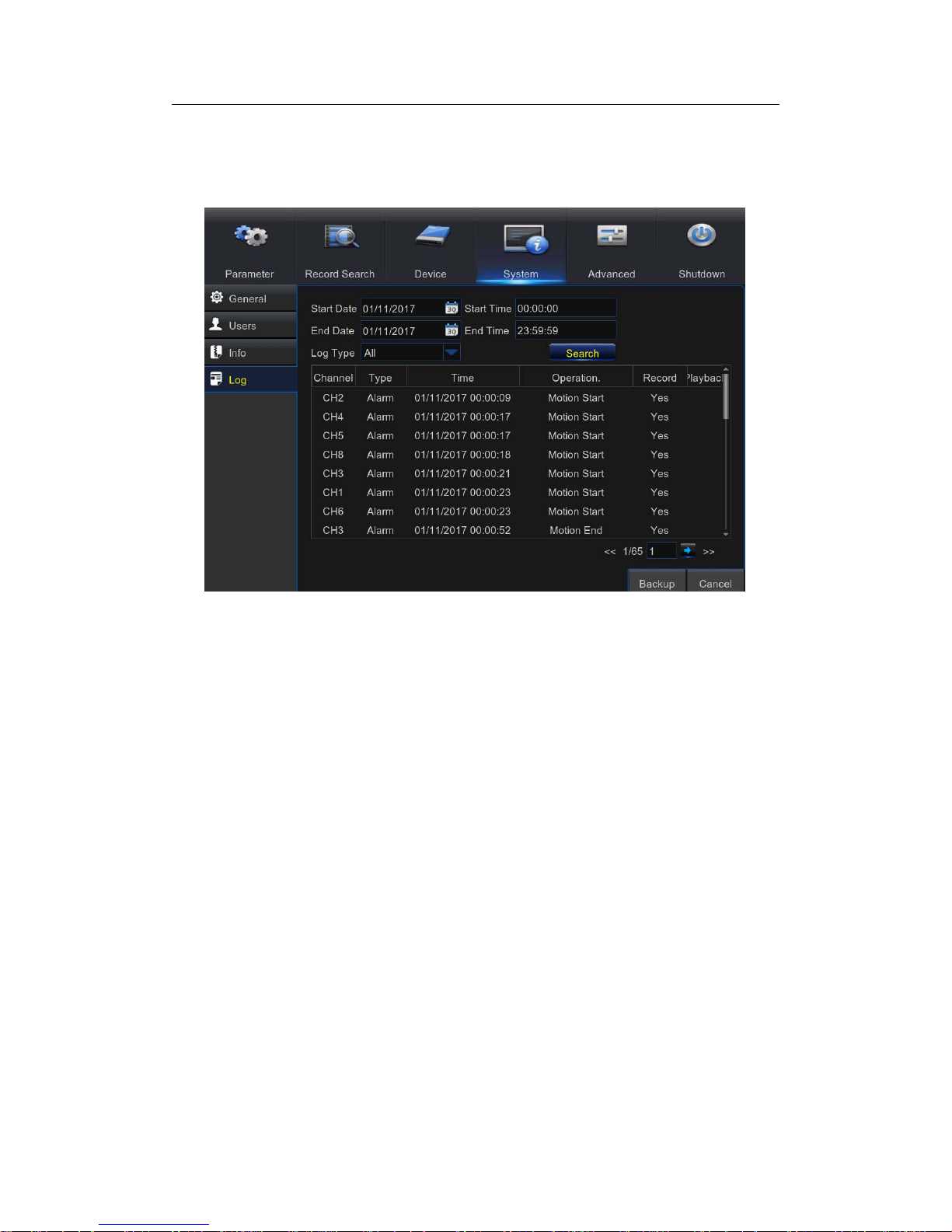
5.8.6 Log
This menu allows you to view a li st of events of system oper ation.
- To search for a log, enter the start time/end time to the respective fields and click
Search.
- To display log details, double-click on the item.
- To backup a log entry, connect an external USB disk to the NVR, click on the log event
and click Backup.
Log Type:Selectthelogtype.
Start Time/End Time: Specify the start and end date/time of the logs you want to review
and/or save on an external USB storage device. Click Search. The logs will be listed on
the table.
Page 62

USER MANUAL
62
5.9 Advanced
5.9.1 Maintain
This menu allows you to configure automatic system maintenance, load factory defaults,
update the firmware settings, upgrade the IPC, etc.
Default User: If you want to log in to the NVR automatically for live view after each startup,
then only administrator user account can be set for auto login.
Auto Reboot: Set enable to reboot the NVR based on a schedule.
Reboot: Set the rebooting schedule based on day, week, or month.
Update: Click to load the update file and then upgrade the firmware. Please do NOT
power off the NVR or remove the USB during the upgrading.
Load Settings: Select this option to import the setting that you have saved earlier, using
the Save Settings function.
Load Default: Use this feature to restore the factory default settings of the NVR. It is
recommended to load defaults for all options, after upgrading the firmware.
Save Settings: Select this option to save the NVR current settings, such as the video
recording settings, network configurations, and etc. to the USB device.
IPC Load Default: Use this feature to restore the factory default settings of IP cameras.
Reboot IPC: To reboot IP cameras.
IPC Upgrade: To upgrade IP cameras firmware. Some IP cameras may not support this
feature.
Page 63
USER MANUAL
63
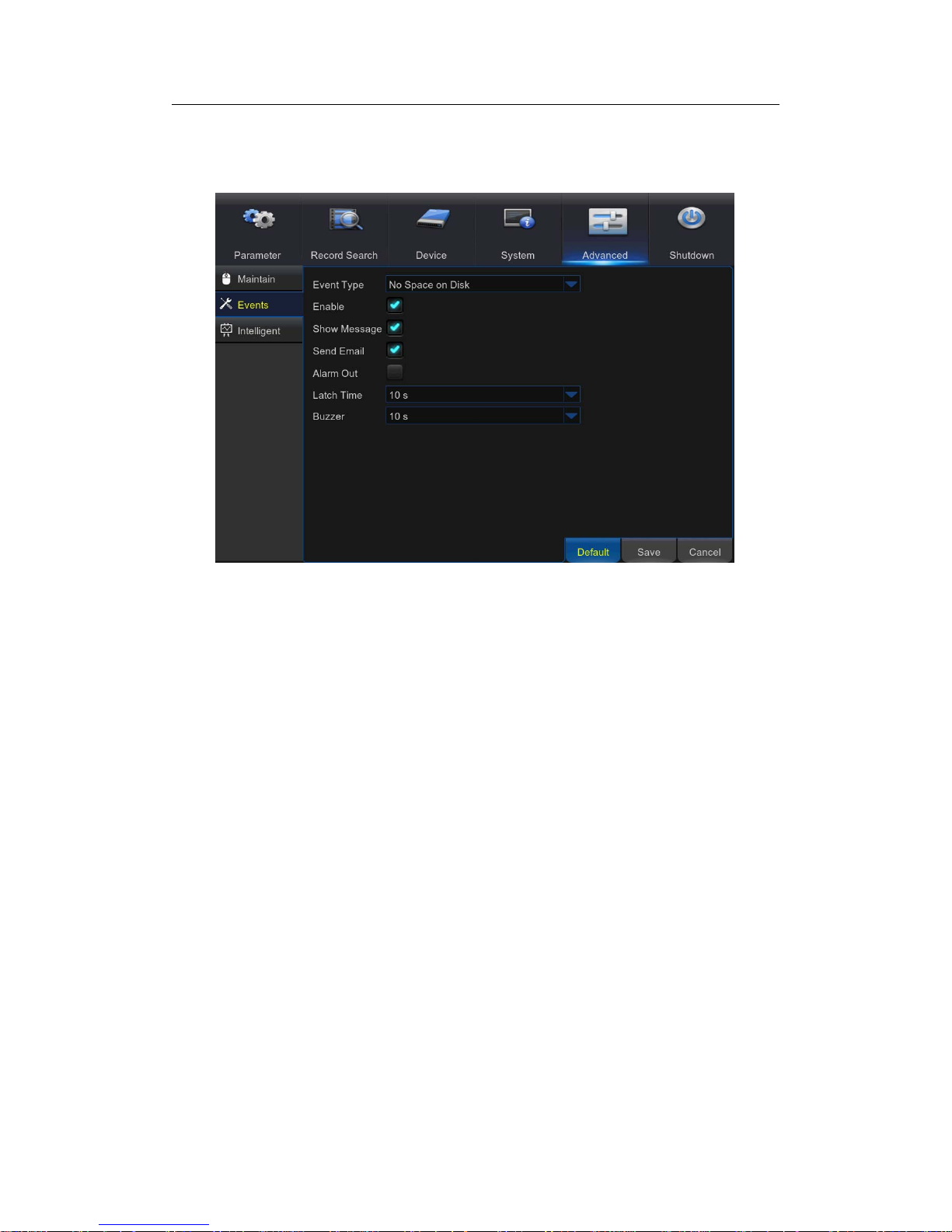
5.9.2 Events
This menu allowsyou to set the typeofevents thatyou want the NVR to informyou.
Event Type: Select the event type. Options are:
-No Space on Disk: When HDD is full.
- Disk Error: If HDD is not detected properly .
- Video Loss: If camera is not detected properly.
Enable: Check the box to enable the monitoring of the event.
Show Message: Check the box to display a message on the s creen when Disk Full, Disk
Error, or Video Loss event happens.
Send Email: Let the NVR to send you an auto-email when an event occurs.
Alarm Out: Click to enable the external alarm device to sound. This is an optional function.
Latch Time: Determine how long the external sensor alarm device to sound (10s, 20s,
40s, and 60s).
Buzzer: Set the buzzer duration when the event occurs (Off/10s/20s/40s/60s). To disable
buzzer, select OFF.
Page 64

USER MANUAL
64
5.10 Intelligent
The NVR provides super performance intelligent functions, including Perimeter Intrusion
Detection,
Line Crossing Detection, Stationary Object Detection, Pedestrian
Detection, Face Detection,andCross Counting.
5.10.1 Schedule
You are able to config the schedule for intelligent detection function. The schedule will be
active in 24 hours x 7 days.
To set the schedule, choose one channel then drag the cursor to mark the slots. The
sky-blue blocks in the time slots will be active for Intelligent detections. The schedule is
valid only for the selected channel each time when you set. If you want to use the same
schedule for other channels, use Copy To function. Click Save to save your settings.
Page 65

USER MANUAL
65
5.10.2 PID(Perimeter Intrusion Detection)
Perimeter Intrusion Detection function detects people, vehicle or other objects which enter
and loiter in a pre-defined virtual region, and some certain actions can be taken when the
alarm is triggered.
Channel: to select the channel you want to configure
Enable: to enable or disable the PID function
Buzzer: to disable or to acti ve the buzzer to emit an alarm tone in 10, 20, 40 or 60
seconds when the detection is triggered
Sensitive: The sensitivity level is from 1 to 4, with a default value of 2. Higher sensitivity
will be easier to trigger the detection.
Scene: Scene setting includes Indoor and Outdoor. Please choose the scene to match
with the place your camera installed.
Post Recording: You can set how long after an event occurs that the NVR will continue to
record.
Latch Time: To configure the external alarm time when the detection is triggered.
Alarm Out: If your NVR support to connect to external alarm device, you can set to emit
an alarm tone.
Show Message: A letter “S” will be displayed on the screen when the PID function is
triggered.
Send Email: If an alarm is triggered, an Email will be sent to your preset email account.
Full Screen: When the detection is triggered, the channel will be enlarged into full screen.
Record Channel: to select the channel(s) you wan t to record when a detection is
triggered.
Area: Click [Setup] to draw a virtual region in the camera picture.
Page 66

USER MANUAL
66
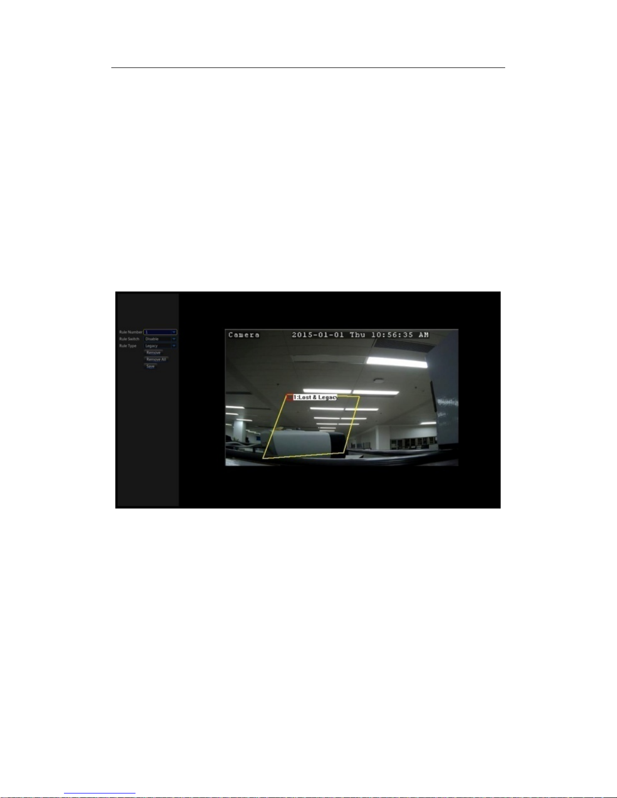
Method to set the PID function:
1. Set the schedule.
2. Choose a channel you want to set, and enable the PID function.
3. Click Area Setup.
4. Choose one of the Rule Number. It is the number of PID area. Maximum 4 areas you
can set for PID function.
5. To enable the detection in Rule Switch.
6. Choose a Rule Type.
AB: NVR will only detect the action from side A to side B;
BA: NVR will only detect the action from side B to side A;
AB: NVR will detect the action from either side B to side A or side A to side B.
7. Use your mouse to click 4 points in the camera picture to draw a virtual region. The
sharp of the region should be a convex polygon. Concave polygon will be not able to
save.
8. Click Save to save your settings.
9. If you want to modify the position or sharp of region, click the red box in the region, the
borders of the region will be changed to red color. Long press the left button of your
mouse to move the position of the region, or drag the corners to resize the region.
10. If you want to remove one of the regions from the camera picture, click the red box in
the region and then click Remove button. Click Remove All will delete all regions.
Notice:
1) The perimeter shall not be too close to the edges/corners of the camera picture, since
it may fail to trigger the detection when the target pass through the edges/corners.
2) The shape of the regions shall not be too narrow/small, since it may fail to trigger the
detection when the target pass through outside the perimeter.
Page 67

USER MANUAL
67
5.10.3 LCD(Line Crossing Detection)
Line Crossing Detection function detects people, vehicle or other objects which
cross a pre-defined virtual line, and some certain actions can be taken when
the alarm is triggered.
Channel: to select the channel you want to configure
Enable: to enable or disable the LCD function
Buzzer: to disable or to acti ve the buzzer to emit an alarm tone in 10, 20, 40 or 60
seconds when the detection is triggered
Sensitive: The sensitivity level is from 1 to 4, with a default value of 2. Higher sensitivity
will be easier to trigger the detection.
Scene: Scene setting includes Indoor and Outdoor. Please choose the scene to match
with the place your camera installed.
Post Recording: You can set how long after an event occurs that the NVR will continue to
record.
Page 68

USER MANUAL
68
Latch Time: To configure the external alarm time when the detection is triggered.
Alarm Out: If your NVR support to connect to external alarm device, you can set to emit
an alarm tone.
Show Message: A letter “S” will be displayed on the screen when the LCD function is
triggered.
Send Email: If an alarm is triggered, an Email will be sent to your preset email account.
Full Screen: When the detection is triggered, the channel will be enlarged into full screen.
Record Channel: to select the channel(s) you wan t to record when a detection is
triggered.
Area: Click [Setup] to draw a virtual region in the camera picture.
Method to set the LCD function:
1. Set the schedule.
2. Choose a channel you want to set, and enable the LCD function.
3. Click Area Setup.
4. Choose one of the Rule Number. It is the number of LCD lines. Maximum 4 lines you
can draw.
5. To enable the detection in Rule Switch.
6. Choose a Rule Type.
AB: NVR will only detect the action from side A to side B;
BA: NVR will only detect the action from side B to side A;
AB: NVR will detect the action from either side B to side A or side A to side B.
7. Use your mouse to click 2 points in the camera picture to draw a virtual line.
8. Click Save to save your settings.
9. If you want to modify the position or length of the line, click the red box in the line, the
color of the line will be changed to red color. Long press the left button of your mouse
to move the line, or drag the terminals to modify the length or position of the line.
10. If you want to remove one of the lines from the camera picture, click the red box in the
line and then click Remove button. Click Remove All will delete all lines.
Page 69

USER MANUAL
69
Notice:
1) The lines shall not be too close to the edges of the camera picture, to avoid any failure
to trigger an alarm when the target cross through it.
2) The lines shall not be set too short, to avoid any failure to trigger an alarm when the
target pass outside it.
Page 70

USER MANUAL
70
5.10.4 SOD(Stationary Object Detection)
Stationary Object Detection function detects the objects left over or lost in the
pre-defined region such as the baggage, purse, dangerous materials, etc., and
a series of actions can be taken when the alarm is triggered.
Channel: to select the channel you want to configure
Enable: to enable or disable the SOD function
Buzzer: to disable or to acti ve the buzzer to emit an alarm tone in 10, 20, 40 or 60
seconds when the detection is triggered
Sensitive: The sensitivity level is from 1 to 4, with a default value of 2. Higher sensitivity
will be easier to trigger the detection.
Scene: Scene setting includes Indoor and Outdoor. Please choose the scene to match
with the place your camera installed.
Post Recording: You can set how long after an event occurs that the NVR will continue to
record.
Latch Time: To configure the external alarm time when the detection is triggered.
Alarm Out: If your NVR support to connect to external alarm device, you can set to emit
an alarm tone.
Show Message: A letter “S” will be displayed on the screen when the intelligent detection
is triggered.
Send Email: If an alarm is triggered, an Email will be sent to your preset email account.
Full Screen: When the detection is triggered, the channel will be enlarged into full screen.
Record Channel: to select the channel(s) you wan t to record when a detection is
triggered.
Page 71
USER MANUAL
71
Area: Click [Setup] to draw a virtual region in the camera picture.
Method to set the SOD function:
1. Set the schedule.
2. Choose a channel you want to set, and enable the SOD function.
3. Click Area Setup.
4. Choose one of the Rule Number. It is the number of SOD area. Maximum 4 areas you
can set for SOD function.
5. To enable the detection in Rule Switch.
6. Choose a Rule Type.
Legacy: NVR will only detect the left-over objects;
Lost: NVR will only detect the lost objects;
Legacy & Lost: NVR will detect both left-over & lost objects.
7. Use your mouse to click 4 points in the camera picture to draw a virtual region. The
sharp of the region should be a convex polygon. Concave polygon will be not able to
save.
8. Click Save to save your settings.
9. If you want to adjust the size of the region, click the red box in the region, the borders
of the region will be changed to red color. Long press the left button of your mouse to
move the whole region, or drag the corners to resize the region.
10. If you want to remove one of the regions from the camera picture, click the red box in
the region and then click Remove button. Click Remove All will delete all regions.
Page 72

USER MANUAL
72
Notice:
1) The area for detection shall be greater than or equal to the size of the detected object,
such as the detection of a white bottle.
2) The detected object cannot be covered.
5.10.5 PD(Pedestrian Detection)
Pedestrian Detection function detects the moving people in a pre-defined
region, and a series of actions can be taken when the alarm is triggered.
Channel: to select the channel you want to configure
Enable: to enable or disable the PD function
Buzzer: to disable or to acti ve the buzzer to emit an alarm tone in 10, 20, 40 or 60
seconds when the detection is triggered
Level: Small, Middle & Big. Small level is recommended to detect objects in long distance.
Big level is recommended to detect objects in short distance.
Scene: Scene setting includes Indoor and Outdoor. Please choose the scene to match
Page 73

USER MANUAL
73
with the place your camera installed.
Post Recording: You can set how long after an event occurs that the NVR will continue to
record.
Latch Time: To configure the external alarm time when the detection is triggered.
Alarm Out: If your NVR support to connect to external alarm device, you can set to emit
an alarm tone.
Show Message: A letter “S” will be displayed on the screen when the intelligent detection
is triggered.
Send Email: If an alarm is triggered, an Email will be sent to your preset email account.
Full Screen: When the detection is triggered, the channel will be enlarged into full screen.
Record Channel: to select the channel(s) you wan t to record when a detection is
triggered.
Area: Click [Setup] to draw a virtual region in the camera picture.
Method to set the SOD function:
1. Set the schedule.
2. Choose a channel you want to set, and enable the PD function.
3. Click Area Setup.
4. Choose one of the Rule Number. It is the number of PD area. Maximum 4 areas you
can set for PD function.
5. To enable the detection in Rule Switch.
6. Choose a Rule Type, only Normal available for this detection.
7. Use your mouse to click 4 points in the camera picture to draw a virtual region. The
sharp of the region should be a convex polygon. Concave polygon will be not able to
save.
8. Click Save to save your settings.
9. If you want to adjust the size of the region, click the red box in the region, the borders
of the region will be changed to red color. Long press the left button of your mouse to
Page 74

USER MANUAL
74
move the whole region, or drag the corners to resize the region.
10. If you want to remove one of the regions from the camera picture, click the red box in
the region and then click Remove button. Click Remove All will delete all regions.
Notice:
1) The region for detection shall not be in the area that people cannot reach.
2) The detected people should be completely surrounded in the region.
5.10.6 FD(Face Detection)
Face Detection function detects the faces of moving people appear in a
pre-defined region, and a series of actions can be taken when the alarm is
triggered.
Channel: to select the channel you want to configure
Enable: to enable or disable the FD function
Buzzer: to disable or to acti ve the buzzer to emit an alarm tone in 10, 20, 40 or 60
seconds when the detection is triggered
Level: Small, Middle & Big. Small level is recommended to detect objects in long distance.
Big level is recommended to detect objects in short distance.
Page 75

USER MANUAL
75
Scene: Scene setting includes Indoor and Outdoor. Please choose the scene to match
with the place your camera installed.
Post Recording: You can set how long after an event occurs that the NVR will continue to
record.
Latch Time: To configure the external alarm time when the detection is triggered.
Alarm Out: If your NVR support to connect to external alarm device, you can set to emit
an alarm tone.
Show Message: A letter “S” will be displayed on the screen when the intelligent detection
is triggered.
Send Email: If an alarm is triggered, an Email will be sent to your preset email account.
Full Screen: When the detection is triggered, the channel will be enlarged into full screen.
Record Channel: to select the channel(s) you wan t to record when a detection is
triggered.
Area: Click [Setup] to draw a virtual region in the camera picture.
Method to set the SOD function:
1. Set the schedule.
2. Choose a channel you want to set, and enable the FD function.
3. Click Area Setup.
4. Choose one of the Rule Number. It is the number of FD area. Maximum 4 areas you
can set for FD function.
5. To enable the detection in Rule Switch.
6. Choose a Rule Type, only Normal available for this detection.
7. Use your mouse to click 4 points in the camera picture to draw a virtual region. The
sharp of the region should be a convex polygon. Concave polygon will be not able to
save.
8. Click Save to save your settings.
9. If you want to adjust the size of the region, click the red box in the region, the borders
Page 76
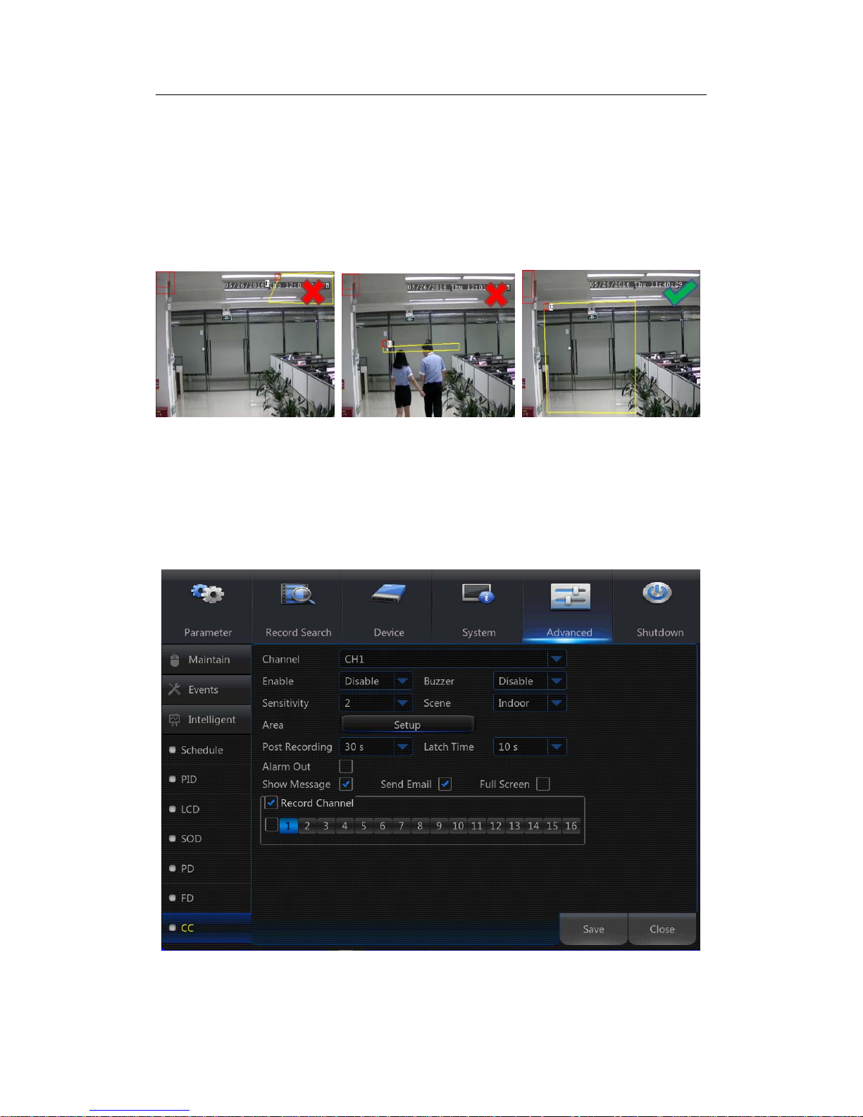
USER MANUAL
76
of the region will be changed to red color. Long press the left button of your mouse to
move the whole region, or drag the corners to resize the region.
10. If you want to remove one of the regions from the camera picture, click the red box in
the region and then click Remove button. Click Remove All will delete all regions.
Notice:
1) The region for detection shall not be in the area that people cannot reach.
2) The region should be include the complete front face.
5.10.7 CC(Cross-Counting)
Cross-Counting function counts the times for moving objects or people across
the virtual lines.
Channel: to select the channel you want to configure
Enable: to enable or disable the CC function
Buzzer: to disable or to acti ve the buzzer to emit an alarm tone in 10, 20, 40 or 60
Page 77

USER MANUAL
77
seconds when the detection is triggered
Sensitive: The sensitivity level is from 1 to 4, with a default value of 2. Higher sensitivity
will be easier to trigger the detection.
Scene: Scene setting includes Indoor and Outdoor. Please choose the scene to match
with the place your camera installed.
Post Recording: You can set how long after an event occurs that the NVR will continue to
record.
Latch Time: To configure the external alarm time when the detection is triggered.
Alarm Out: If your NVR support to connect to external alarm device, you can set to emit
an alarm tone.
Show Message: A letter “S” will be displayed on the screen when the intelligent detection
is triggered.
Send Email: If an alarm is triggered, an Email will be sent to your preset email account.
Full Screen: When the detection is triggered, the channel will be enlarged into full screen.
Record Channel: to select the channel(s) you wan t to record when a detection is
triggered.
Area: Click [Setup] to draw a virtual region in the camera picture.
Method to set the CC function:
1. Set the schedule.
2. Choose a channel you want to set, and enable the CC function.
3. Click Area Setup.
4. Choose one of the Rule Number. It is the number of virtual lines you can draw.
Maximum 4 lines.
5. To enable the detection in Rule Switch.
6. Choose a Rule Type
Object: Will count for only moving objects.
Pedestrian: Will count only moving people.
7. Use your mouse to click 2 points in the camera picture to draw a virtual line. From
Side A to Side B is Enter, from Side B to Side A is Exit.
Page 78

USER MANUAL
78
8. Click Save to save your settings.
9. If you want to modify the position or length of the line, click the red box in the line, the
color of the line will be changed to red color. Long press the left button of your mouse
to move the line, or drag the terminals to modify the length or position of the line.
10. If you want to remove one of the lines from the camera picture, click the red box in the
line and then click Remove button. Click Remove All will delete all lines.
Notice:
1) The lines shall not be too close to the edges of the camera picture, to avoid any failure
to trigger an alarm when the target cross through it.
2) The lines should be in the area that detected object can be reach.
2) The lines shall not be set too short, to avoid any failure to trigger an alarm when the
target pass outside it.
Page 79

USER MANUAL
79
View the Cross-Counting Result
To System Intelligent Analysis menu, you will be able to search & view the statistical
result of cross counting.
The statistical result can be queried by Daily / Weekly / Monthly / Annual.
5.10.8 View Log of Intelligent Analysis
Click the icon in the upper right corner of the preview interface, you can view the
alarm events of intelligent analysis.
Page 80

USER MANUAL
80
5.11 Shutdown
Manually turn off or reboot the NVR.
Page 81

USER MANUAL
81
Chapter 6 Web Application Manager
Use the Web Client to remotely access your NVR at any time via a PC. Before you access
the Web Client, you need to ensure that the network settings of the NVR are configured
properly. The most convenient and easiest way is if you have set the NVR a static IP
address (please see“5.4.1 Network”). It means you only need to open the web browser on
your PC and type in the static IP address you have set on the NVR. However, if the IP
address of the NVR is assigned by a DHCP server (see“5.4.1 Network”), then it means
that each time you reboot the NVR, the IP address changes. In this case, ask if your ISP
can provide you a static IP address. If not, then configure the DDNS service. See the
network settings in “5.4.5 DDNS”.
6.1 Web Plugin Download and Installation
To access the Web Client, do the following:
For IE/Chrome/Firefox:
1) Launch the explorer on your PC and enter the NVR static IP address or DDNS domain
name (Host Name) you have set on NVR in the URL box.
Page 82

USER MANUAL
82
2) For the first time when you run the web client, system will require to install the web
client plugin. Click download to download the plugin and install to your computer.
3) After installing the plug-in, close & launch again your browser and repeat step 1 to
open the login page. Input your user name and password to login the web client.
Note: If you use Google Chrome, please use Version V41 or below. If you use V42 to
V44, you need to enable NPAPI plugins. Please enter chrome://flags/#enable-npapi
on URL bar to find and enable NPAPI. It doesn’t support V45 or above so far
Page 83

USER MANUAL
83
For Mac SAFARI:
1) Launch the Safari on your Mac, and enter the NVR static IP address or DDNS
domain name (Host Name) you have set on NVR in the URL box.
2) Download the plug-in "SurveillanceClient.dmg", locate the downloaded file and
double click it.
3) Click on "Continue" --> "Install". Enter user name and password for Mac
computer, Click on "Install Software" --> "Close" to finish installation.
Page 84

USER MANUAL
84
4) Shut down Mac SAFARI browser and restart it, and then enter IP address of NVR in
address bar to access login page.
6.2 Web Client Manager
The web client supports to full control the NVR with administrator account. Please make
sure to protect your user name & password for preventing illegal login.
6.2.1 Live Interface
This is the first screen that opens after you have logged in to the Web Client. Here you
can open or close live preview, record video to local computer manually, take snapshots of
the screens, PTZ control, color adjustment, etc.
1. Buttons on a single live interface:
: Volume switch
Page 85

USER MANUAL
85
: Record switch: the remote record switch of client. Record will be automatically
saved to a specified position on PC after the function is enabled.
: Snapshot: Capture the selected live image and save it to a specified position
on PC. The image is saved as *.bmp format.
:Digital ZOOM.
: Open the images on Live window.
:Close all the Live channels
: Switch display mode in channel window
: Open the images on Live window.
:Stretch.
: Original proportions.
: Click to maximize the current window to full screen. Right click to popup menu
option and select Exit Full Screen.
2. Video Control
Hue: Adjust the chromaticity of video
Bright: Adjust the brightness of video
Contrast: Adjust the contrast of video
Saturation: Adjust the saturation of video
Page 86

USER MANUAL
86
3. PTZ Control
:PTZ direction control and automatic scanning button
:PTZ movement speed adjustment
:
Adjust the zoom +, -
:Adjust FOCUS +, -
:
Adjust the IRIS +, -
:
Set, clear and jump points
:
Start cruising and stop cruising
6.3.1 Playback
Click to enter into Playback interface to remotely view the records in
NVR HDD.
Note:It supports 4 channels playback.
Page 87

USER MANUAL
87
6.3.1.1 Record Search
Record playback procedure
Firstly, select the date you want to check and select 4 channels. Any record files in
current channel at current date will be displayed in the status bar of the interface.
Secondly, select record type (Normal record, Alarm record and All) and channels, and
select stream (Mainstream and Substream).
Then click “
”, and time axis panel will display specific time
quantum, On the time axis, red part stands for alarm record, yellow stands for normal
record and original part stands for no record during this period.
Before playback, choose to enable playback 4 channels synchronously. If you
tick-select “
”, that means the selected channel will playback
synchronously; otherwise, you could separately control the channels playback.
Thirdly, click to start record playback. When mouse curse is moving on the time
axis, the time point of current position will be displayed on the time axis screen. Click the
icon or to zoom
in/out the time bar display ratio.
Page 88

USER MANUAL
88
"Stream" select "SubStream", select the channel, click search video, and click
play.
Page 89
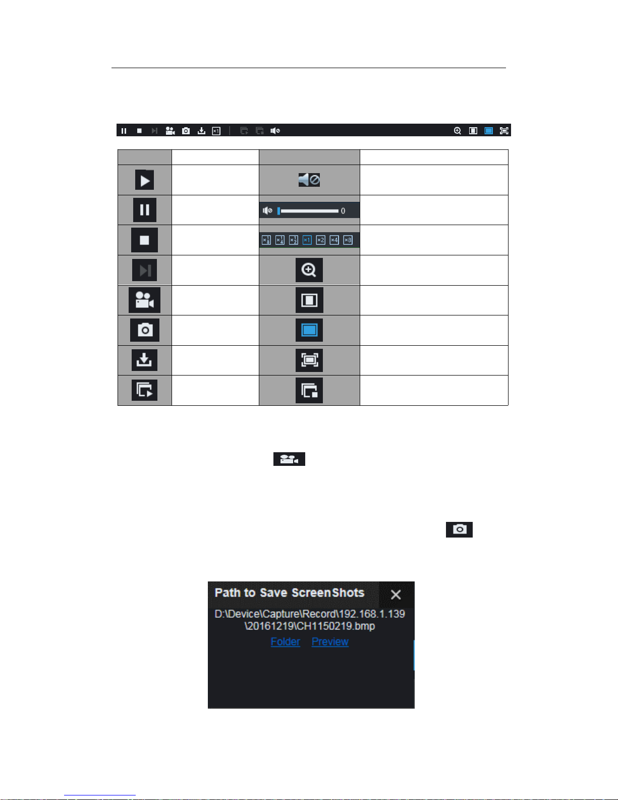
USER MANUAL
89
6.3.1.2 Playback Control
Playback control bar
Detailed brief description is shown as below list
Key Description Key Description
Play Enable the volume switch
Pause Volume adjustment bar
Stop
Slow playing 1/2,1/4, 1/8, Fast
playing 1/2/4/8
By frame Digital ZOOM
Record Clip Original proportions
Snap Stretch
Download Full Screen
Open all the
playback channels
Stop playing all the playback
Table 5-1
Record file clip
After opening playback, click icon
to clip the selected file; and click again to stop
the clip function. Then playback clip is successfully done. Record clip file will be saved as
*.264 format.
Snapshot function
Move the mouse curse to the channel you want to capture, and click
icon to
capture the live images remotely. After capturing the images successfully, a path prompt
box will be popped up.
Page 90

USER MANUAL
90
Thecapturedfilewillbesavedasbmpformat.
Record file download
Click download icon
on the control bar to display all the matched record fi le
according to the search conditions of channels.
Tick-select the record file you want to download and click [Start download] .System will
download the record file in sequence and save to local PC. The downloading file will be
displayed in percentage form. After downloading finishes, “Complete” will be displayed on
the status bar.
Page 91

USER MANUAL
91
6.3.2 Remote Setting
Here you can remotely configure the settings of the NVR. Please see “Chapter 5 NVR
Menu” formore information.
6.3.3 Local Setting
Record Path: Set the path to save manual recordings on your PC’s local drive.
Download Path: Set the path on your PC’s local drive where you want to download
recordings from the NVR.
Snapshot Path: Set the path to save manual snapshots on your PC’s local drive.
Save: Click Save to save the modifications.
File Type: Choose your preferred file type for manual recordings.
Page 92
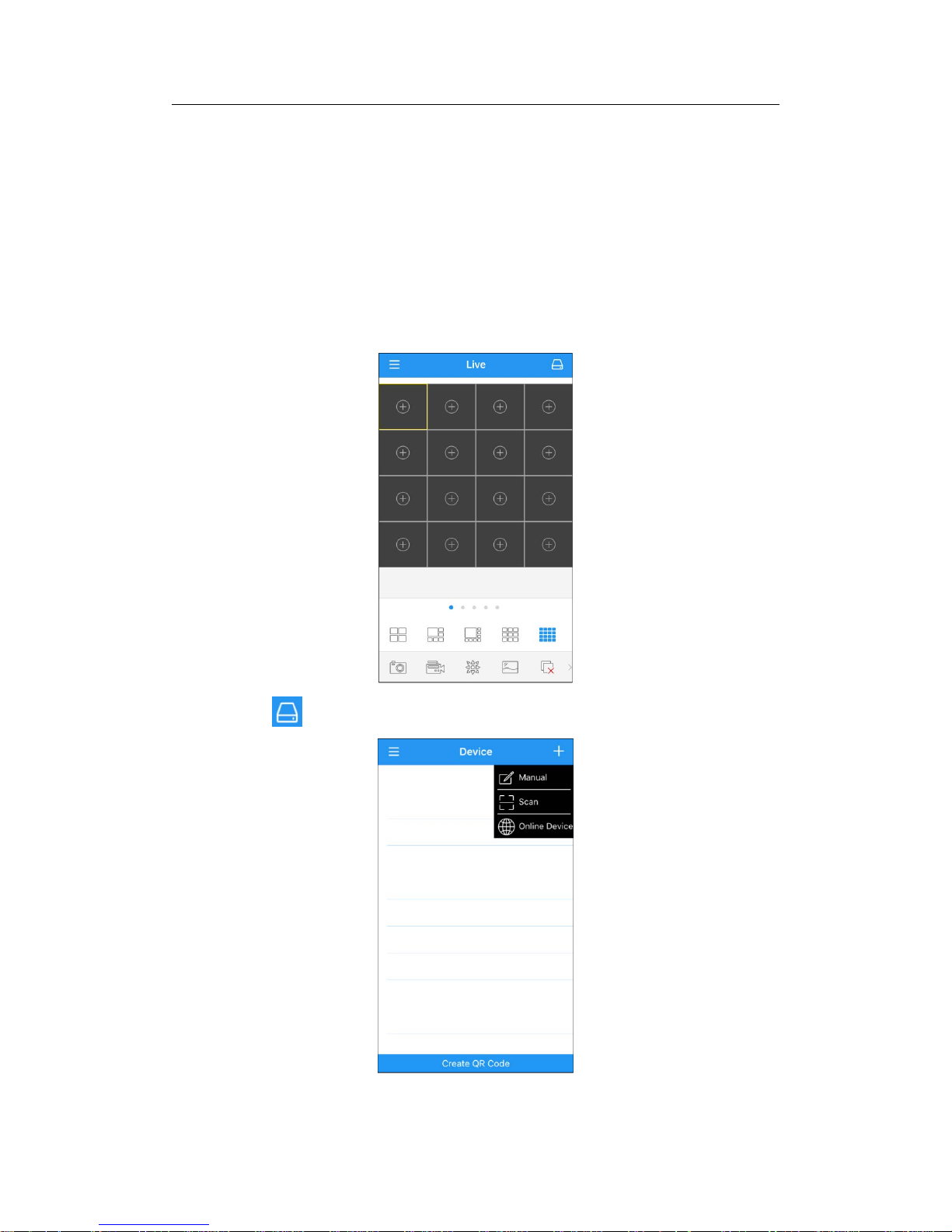
USER MANUAL
92
Chapter 7 Remote Access via Mobile
Devices
The NVR supports to remote access via mobile devices based on Android & iOS
operating system.
1) Search RXCamView from Google Play Store for android devices or App Store or iOS
devices and install.
2) Run the app, it will display the live view screen.
3) Touch the icon to open device list page, touch + to add device.
Page 93
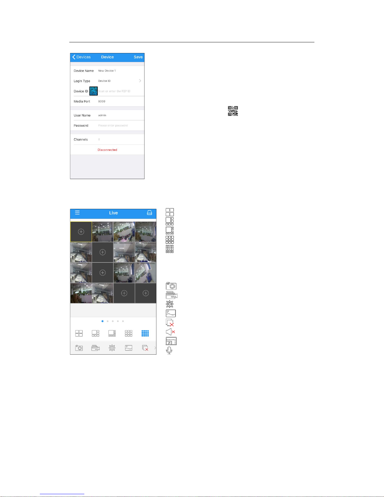
USER MANUAL
93
4) Choose “Manual”, and input the NVR information.
5) After all settings completed, touch Save to save, the app will turn to Live view display
if the device is well connected.
Device Name: Input the name you want to display
Login Type:DeviceIDandIP/DOMAIN
-Device ID: For P2P connection.
-IP/DOMAIN: IP address or Domain name of the NVR
Device ID/IP Address: Input the P2P ID or IP address/Domain
name. You can touch the
icon to scan the P2P QR code
to add device.
Media Port: Input the media port in NVR network setting
User Name / Password: Input the user name & password of
the NVR.
Channels: System will display the number of channels of the
NVR after connected.
4 pictures display
6 pictures display
8 pictures display
9 pictures display
16 pictures display
Note: The app will display max. 16 pictures in one screen. You
can s lip the screen to move to next screen to view other 16
pictures. Total 80 pictures can be displayed.
Snap shoot the pictures
Record the live view video to your mobile device
PTZ control
Picture quality
Close all live view pictures
Turn Off/On Audio
Adjust the video scale
Dual-way speaker (If your NVR support)
Page 94

USER MANUAL
94
6) Touch icon to open the Menu list where you can check & configure the live view,
playback, local recorded videos, captured pictures, push alarm notifications, Device
manager, Local Setting & Help documents.
Page 95

USER MANUAL
95
Chapter 8 Appendix
8.1 Troubleshooting
1. Q: What can I do if the system does not detect the HDD?
A: Check if the power s upply system is properly connected and data cord and power
cables are securely connected, and if something wrong with the HDD interface. Or
you may check if your HDD is supported by referring to the s pecif ications or
descriptions.
2. Q: I have changed the password but forget the new password, how can I access the
system?
A: If you forget system password, please consult with our technical personnel. We
strongly suggest user to set password easy to be remembered and relatively safe. If
you have safety requirement, please do not set very simply password, such as
000000.
3. Q: We see abnormal video signal or even no video signal by connecting the NVR and
camera together. Power supply for both devices is OK. What is wrong?
A: Check network cable at NVR side to see if the cable is firmly connected and if it is
worn out and needs to be replaced.
4. Q: How to prevent NVR from being influenced by heat?
A: The NVR needs to dissipate heat while it is running. Please place the N V R in a
place with good air circulation and away from heat sources to ensure stability and life
of the NVR.
5. Q: The remote controller doesn’t work while the monitor screen is OK and panel keys
are functional. Why?
A: Operate again by aiming the remote controller at the IR receiver on front panel. If it
still doesn’t work, please check if the batteries in the remote controller are dying. If
not, check if the remote controller is broken.
6. Q: I want to take out HDD from my PC and install it in NVR. Can it work?
A: All HDDs supported by the system can be used. But remember, once NVR runs,
the data on your HDD will be lost.
7. Q: Can I playback while recording?
A: Yes. The system supports the function of playing while recording.
8. Q: Can I clear some records on HDD of NVR?
A: In consideration of the file security, you may not clear part of records. If you want to
remove all the records, you can format HDD.
9. Q: Why can’t I log in NVR client?
A: Please check if the network connection settings are correct and RJ-45 port is with
good contact. And check if your account and password are correctly input.
10. Q: Why can’t I find any records during playback?
A: Please check if the data line connection for HDD is OK and system time is
properly adjusted. Try a few times and restart. If it still doesn’t work, check if the
HDD is broken.
11. Q: Why doesn’t dynamic detection work?
A: Please check if the motion detection alarm setting at IPC side is correct and if the
sensitivity is set too low.
12. Q: Why doesn’t alarm work?
A: Please check if the alarm setting, alarm connection and alarm input signals are
correct.
Page 96

USER MANUAL
96
13. Q: Why does buzzer keep alarming?
A: Please check the alarm setting, check if motion detection function is enabled and
object motion is detected all the time and if I/O alarm is set as Always Off. Besides,
refer to corresponding HDD alarm setting.
14. Q: Why can’t I stop recording by pressing “STOP” button or click “Stop Recording” in
context menu?
A: Pressing Stop button can only stop manual record. If you want to stop Scheduled
recording in certain time quantum, please change the setting to No Record. To stop
Startup recordin g, please change record mode to scheduled recording or manual
recording. Then you may stop recording by the prescribed methods. And another
way of stopping recording is to set channel in record setting as off.
8.2 Usage Maintenance
1. To shut down NVR, please firstly shut down the system and then turn off the power.
Do not turn off the power directly or HDD data will be lost or damaged.
2. Please keep NVR away from heat sources or places.
3. Clean the internal dust regularly. Make sure the good ventilation of NVR so as to
ensure the good heat dissipation.
4. Please do not hot plugging cables at ports, or the ports may be damaged.
5. Please check the HDD cable and data cable regularly to see if they are ageing.
6. Please prevent the audio and video signals of NVR from being intervened by other
electronic devices, and prevent the HDD from being damaged by static electricity and
induced voltage.
7. If the network cable is frequently plugged, it is suggested to replace connecting line
regularly, or the input signal may be unstable.
8. This is A class product. It maybe bring wireless interference in life. Under this situation,
it need user to make measures.
8.3 System Connection Diagram
Page 97

USER MANUAL
97
8.4 Accessories (Goods in kind prevail)
CAUTION
RISK OF EXPLOSION IF BATTERY IS REPLACED BY AN INCORRECT TYPE
DISPOSE OF USED BATTERIESACCORDING TO THE INSTRUCTIONS
USB Mouse CD Warranty Card
Powe
r
A
dapter
(Good in kind prevail)
UserManual
Remote Controlle
r
Page 98

USER MANUAL
98
The material in this document is the intellectual property of our
department .
No part of this manual may be reproduced, copied, translated,
transmitted, or published in any form or by any means without our
department prior written permission.
Our products are un de r continua l improvement and we rese rve the right to
make changes without notice. But n o guarantee is given as to the correctne s s
of its contents.
We do not undertake any responsibility for the harms cause by using our
product.
The model of the product s in the user's manual on ly for recog nitio n, but
these names also perhaps are belong to other company's registered
trademark o r the copyrig ht.
The product picture may differ from the actual product, only for your
reference. The accessories will probably be different according to the
differ ent sell ing ar eas. For detai ls o f acce ssories, please refer to your local
distribut or.
Copyright r es erved
 Loading...