

Page 1

4
IP Camera User Manual
(WEB interface)
Page 2

5
Welcome
Thank you for purchasing our GW POE IP Cameras!
This user manual is designed to be a reference tool for the connection and operation of your camera.
Here you can find information about the camera’s features and functions, as well as troubleshooting information.
GW Security Inc.
Official Website: www.gwsecurityusa.com
Support Team: support@gwsecurityusa.com
Phone: 626-350-0555
Business Hours: Monday ~ Friday from 9:00AM to 5:30PM PT.
Overview
Main content of this manual include:
Title
Content
Internet connection
Introduction to IP camera connecting guide and web login guide
Preview
Introduction to IP camera Preview’s main functions and usage
Playback
Introduction to record playback’s main functions and usage
Settings
Introduction to the web setting’s main functions and usage
Symbol Definition
There are some Symbols in this manual; their meanings are explained by the following:
Title
Content
Warning
There is a potential danger; alert users there may be potential harm
Caution
There is a potential risk that could lead to camera damage or loss of data
Description
Additional information, as an additional remark for main content.
P r e f a c e
Page 3

6
Important Safeguards and Warnings
1.Electrical Safety
All installation and operation should conform to your local electrical safety codes.
The product must be grounded to reduce the risk of electric shock.
We assume no liability or responsibility for any fires or electrical shock caused by improper handling or
installation.
2.Transportation Security
Heavy stress, violent vibrations, and excess moisture should not occur during transportation, storage, and
installation of the device.
3.Installation
Handle the device with care. Keep the device right side up.
Do not apply power to the camera before completing installation.
Do not place objects on top of the camera.
4.Repair Professionals
All the examination and repair work should be done by qualified service engineers.
We are not liable for any problems caused by unauthorized modifications or user-attempted repair.
5.Environment
The camera should be kept in a cool, dry place away from direct sunlight, flammable materials, explosive
substances, etc.
This product should be transported, stored, and used only in the specified environments as stated above.
Do not aim the camera at a strong light source, as it may cause overexposure of the picture, and may affect the
longevity of the camera’s sensors.
Ensure that the camera is in a well ventilated area to prevent overheating.
6. Operation and Maintenance
Do not touch the camera sensor or lens directly.
To clean dust or dirt off of the lens, use an air blower or a microfiber cloth.
Page 4

7
D i r e c t o r y
1 Connection Guide................................................................................................................................................8
1.1 Connecti on Guide ...................................................................................................................................8
1.2 Logging into the Web Interf ace ........................................................................................................ 9
2 Preview............................................................................................................................................................... 12
2.1 Main Men u...............................................................................................................................................12
2.2 Funct ion Bar...........................................................................................................................................13
2.3 Side bar .................................................................................................................................................... 14
3 Playback..............................................................................................................................................................15
4 Settings................................................................................................................................................................16
4.1 Local Configuratio n .............................................................................................................................16
4.2 Config Media.......................................................................................................................................... 16
4.2. 1 Audio Vi deo .................................................................................................................................16
4.2. 2 Privacy.......................................................................................................................................... 17
4.2. 3 Image.............................................................................................................................................18
4.2. 4 ROI -Region of Interest............................................................................................................20
4.2. 5 OSD.................................................................................................................................................20
4.3 Network....................................................................................................................................................21
4.3. 1 TCP/IP........................................................................................................................................... 21
4.3. 2 PPPOE............................................................................................................................................22
4.3. 3 DDNS Clie nt.................................................................................................................................23
4.3. 4 Email..............................................................................................................................................24
4.3. 5 FTP..................................................................................................................................................24
4.3. 6 Bonjou r .........................................................................................................................................25
4.3. 7 SNMP ..............................................................................................................................................26
4.3. 8 HTTPS............................................................................................................................................27
4.3. 9 P2P................................................................................................................................................. 27
4.4 Alarm Co nfig...........................................................................................................................................28
4.4. 1 Motion De te ction...................................................................................................................... 28
4.4. 2 Video Bind & Alarm.................................................................................................................30
4.5 Storage ......................................................................................................................................................31
4.5. 1 Schedule.......................................................................................................................................31
4.5. 2 SD Storage....................................................................................................................................32
4.5. 3 Snapsh ot.......................................................................................................................................32
4.5. 4 Destinati on................................................................................................................................. 33
4.5. 5 NAS ..................................................................................................................................................34
4.6 System.......................................................................................................................................................34
4.6. 1 Maintenance............................................................................................................................... 34
4.6. 2 Device Info .................................................................................................................................. 35
4.6. 3 Set Time........................................................................................................................................35
4.6. 4 User Admin..................................................................................................................................36
Glossary of Terms....................................................................................................................................................37
Page 5
8
1 Connection Guide
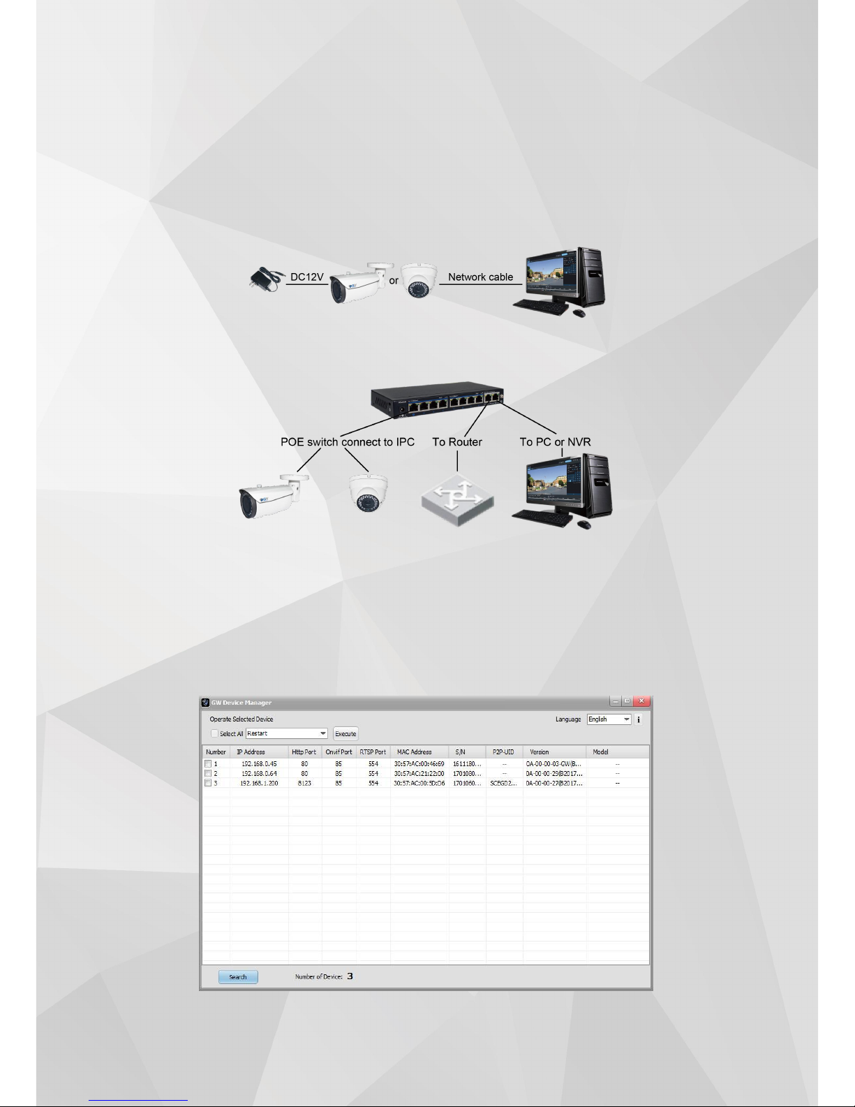
1.1 Connection Guide
There are two mai n methods to con nect the ca mera:
Pic 1-1 Network cabl e connec tion diagram
Pic 1-2 POE swi tch or rou ter connect ion diagram
Before accessing the IP camera, user ne eds to acquire the IP camera ’s IP address. User can
find th e IP address by using the “GW Device Manage r ” sof tware in cluded in the CD.
From the GW Devic e Manager soft ware, left click on “sea rch ” to find all the avail abl e IP
cameras in you r current LAN ne twork. The software will display the IP camera’s IP addres s, port
numb er, MAC add ress, Serial Number, UID, versi on info, and model nu mbe r. Please use th e
pict ure below as referen ce.
Page 6
9
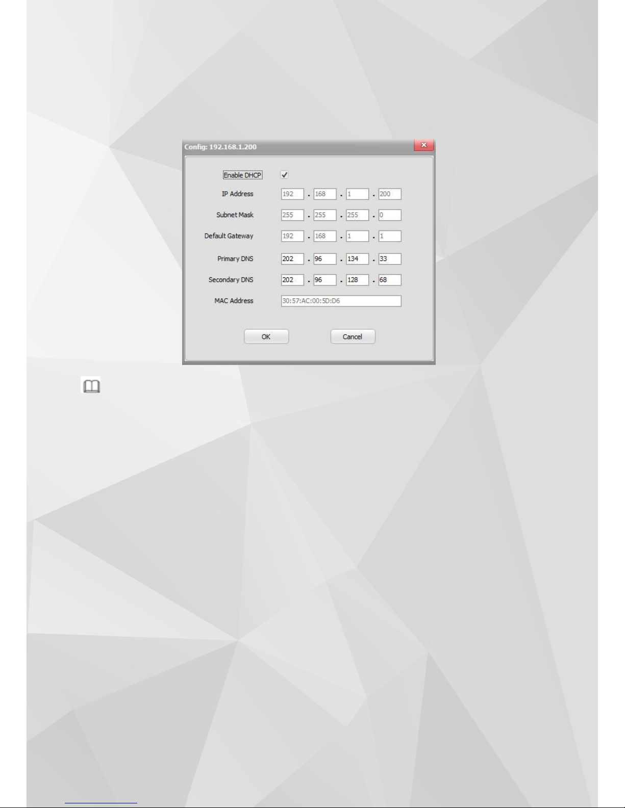
If the IP address found does not match yo ur computer ’s IP su bnet, pleas e use GW De vice
Mana ger to modi fy the IP came ra ’s netwo rk in fo.
From the GW Devic e Manager, sel ect the IP camera to be mod ified and right click, then
choo se Netwo rk Configuration. Ple ase use the be low pict ure as reference.
Note
The IP camera wil l have DHCP turn ed on by defa ult. Please connect th e IP cam era to a
network with DH CP availab le. If there is no DHCP server available , the IP ca mera’s IP address
will default to 192.168.0 .66 .
Defaul t Userna me and Passwo rd: admi n/adm in.
1.2 Logging into the Web Interface
When us er acces ses th e web inte rface for the first time, “VLC media play er” is needed in
order for the video to sh ow co rrect ly.
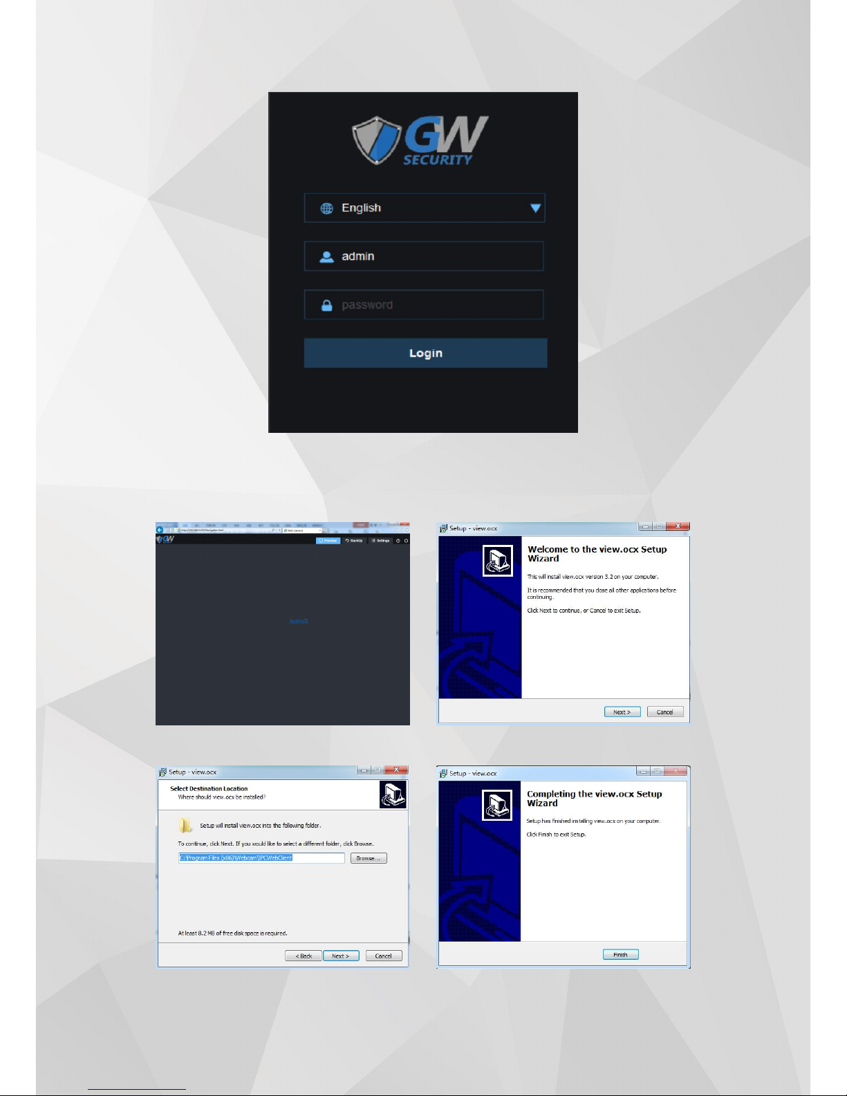
To access the web interface, plea se fo llow the steps below.
Step 1: Open Inte rnet Explorer and inpu t the IP camera’s IP add ress into the URL address bar.
Step 2: When th e user interface is shown, en ter the default usern ame: admin and password: admin
to log into th e web interface. An exa mple of the lo gin scre en is sh own below.
Page 7
10
Step 3. Install the plug-in when prompted :
① ②
③ ④
Page 8
11
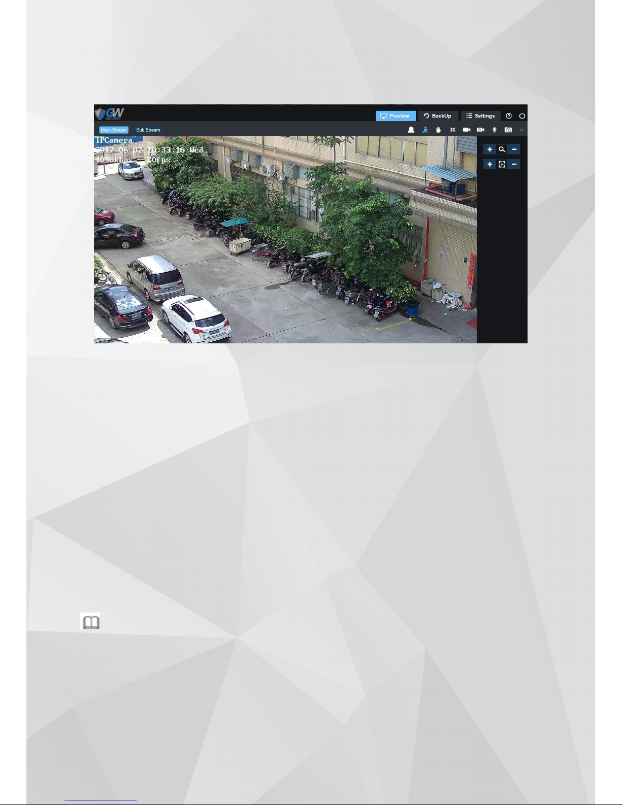
Step 4. Refresh the we b page after the plug-in in stalled su cce ssfully. Repe at step 2 to log into th e
web inter fa ce again. The web interface is shown below :
Available from the We b Interface:
• Liv e Preview
• Record Playback
• Save a recordin g onto the local compute r.
• Modify IP camera parameters, chang e settings , change video qu ality an d system time.
Mini mum Requ ireme nt
:
• 2.0 Gh z and up CPU
• 2GB an d up RAM
• 10/100Mbp s network
• 1024 x 76 8 or up Monitor Resolution
Supp orted OS :
• Mic rosoft Wind ows XP, Microsoft Windows Vista, Microsoft Windows 7,M icros oft Windows
8,Mi croso ft Windows 10
• Mac OS
Note:
The Internet browser mentio ned in the man ual is Intern et Explorer. Ple ase use IE version 9 and up to
acce ss the web interface.
Page 9
12
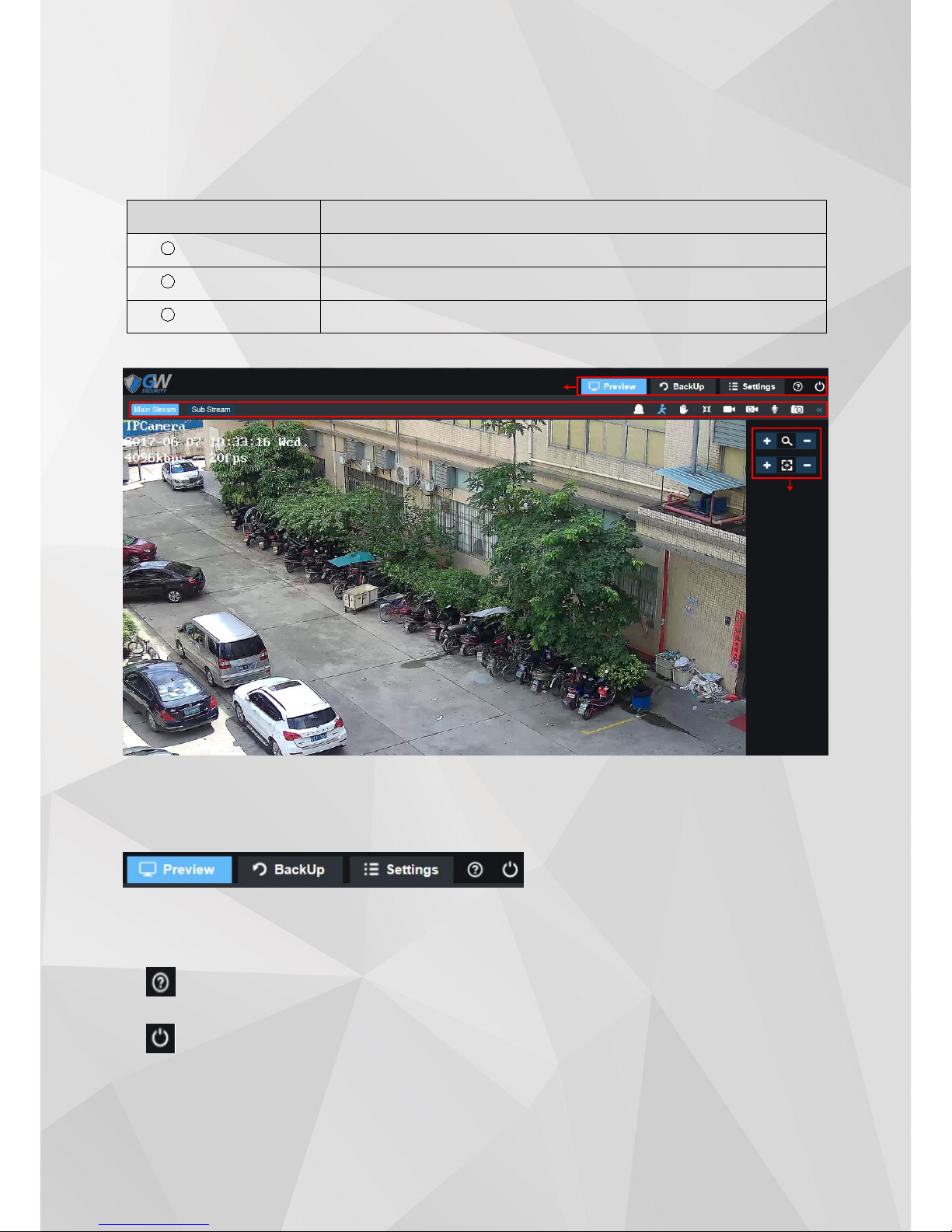
2 Preview
Web client preview has included the 3 function bar:
Parameter
Desc ription
1
Menu Ba r
2
Status Ba r
3
Side bar
Web client preview picture reference below
2.1 Main Menu
For de tail information of each sections , pleas e see (section 2 Preview, secti on 3 Ba ckup, sect ion 4
Settin gs)
Click here for help
Click here to log out
②
Page 10
13
④⑤③
⑩
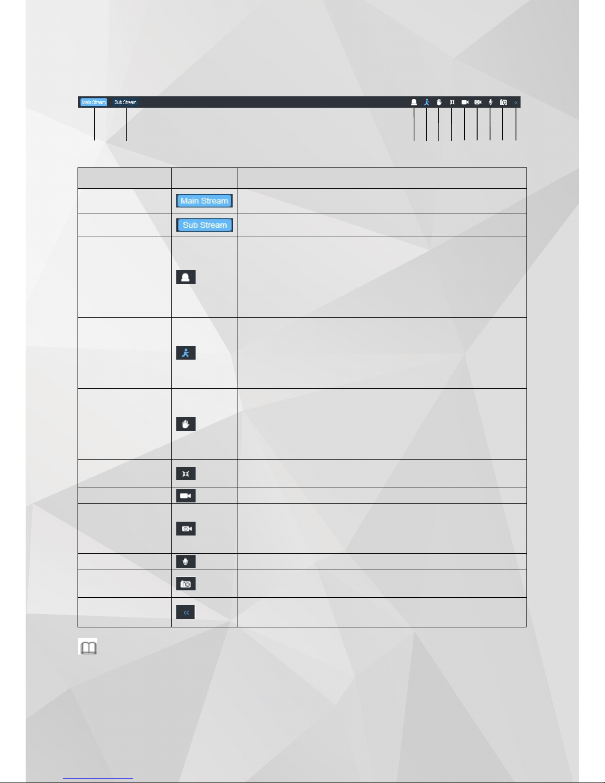
2.2 Function Bar
Paramete r
icon
Desc ription
① Main St ream
Switch to main stream; Main stre am is the recorded bit rate
with high re solut ion
② Sub Strea m
Switch to sub stream; Su b stream is the lower re solution an d
bit rate used when ban dwi dth is a restricti on.
Sens or alarm
Disp lay the Se nso r Alarm Status:
White: Senso r alarm has no t been set up
Blue: Sensor Al arm ha s been set up and acti vated
Sensor Alarm is be en triggered
Note: Onl y the status is shown here . For detail setting, pl ease
refer to section 4.3.2
④Motio n Alarm
Disp lay the Motio n Alar m Sta tus:
White: Motion Alarm has not been set up
Blue: Motion Alarm ha s been set up and acti vated
Red: Motion Alarm is been triggered.
Note: Onl y the status is shown here . For detail setting, pl ease
refer to section 4. 4.1
⑤ Video Cover
Alar m
Disp lay the Video Co ver Alar m status :
White: Video Cove r Alar m has no t been set up
Blue: Video Cover Alarm has been set up and acti vated
Red: Vide o Cover Alarm is be en triggere d.
Note: On ly the status is show n here. For detail se tting , please
refer to section 4. 4.2
⑥ Full screen
Sing le left click th is icon will bring the video to full screen.
Doub le click on th e video or hit “ESC” to ex it full screen
⑦ Manual Record
Sing le left click wi ll turn on man ual record mo de
⑧ Schedu le
Record
Show th e statu s of Schedu le Record:
White: Sched ule Record ha s not been set up.
Blue: Schedule Record has be en set up and is curre nt ly
recording
⑨ Audio
Turn on/off the Audio
⑩ Screen
Capture
Sing le left click wi ll captu re a scree nsh ot. For the scre enshot
save path, please refer to section 4.1
⑪ Di splay /Hide
Side bar
Disp lay/hide side bar
Note
Sens or alarm, Audio , Vid eo cover alarm is not availab le for some mode ls.
①
②
⑥⑦⑧
⑨
⑪
Page 11
14
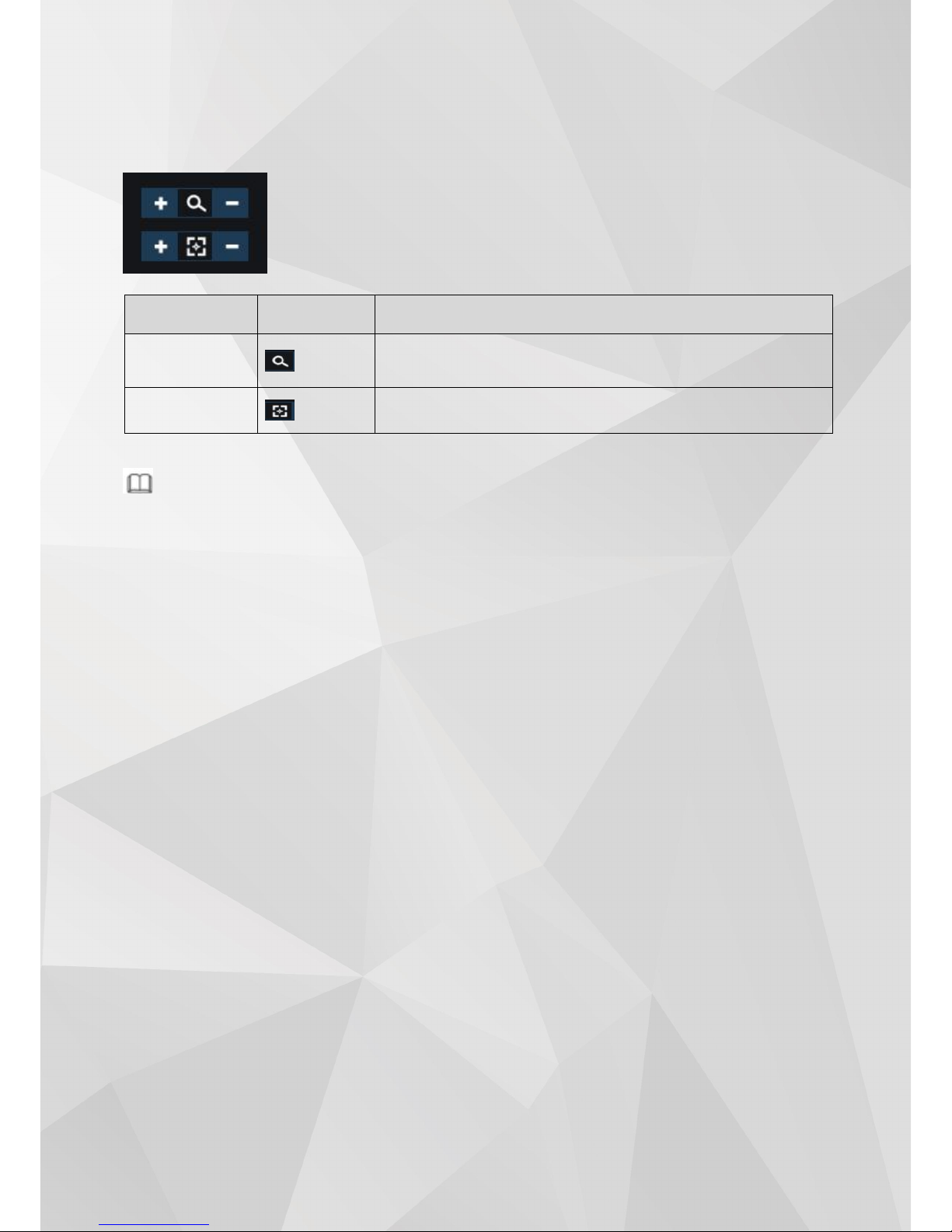
2.3 Side bar
Zoom an d Foc us
Note
Only mo del with motorized zoom su pport this fe ature.
Parameter
icon
Desc ription
Zoom
Adju st th e camera ’ s Zoom level; si ngle lef t click or left click
and hold on the + and – sig n for ad justm ent.
Focus
Adju st th e focus; sing le left click or left click an d hold on the +
and – sign for adj ustme nt.
Page 12

15
3 Playback
Web client playback picture reference below
Step1 Select “ File Typ e”,“Video” and“Im age ” opt ion .
Step2 Select “ Date Source” ,“ SDC ard ” and “ Local option ” .
Step3 Select date an d time .
Step4 Cli ck to play video and pi cture .
Parameter
icon
Desc rip tion
① Slow forwa rd
Clic k this button for slow play back
② Last
Clic k this button to play last video or picture
③ Stop
Clic k this button to sto p playba ck
④ Next
Clic k this button to play next video or picture
⑤ Fast Fo rward
Clic k this button to spee d up playba ck
⑥ Capture
Clic k this button to capture picture
⑦ Aud io
Clic k this button to turn on /off audio
Page 13

16
4 Settings
Web Clie nt’s Sett ing has 6 op tio ns: Loca l Configuration Config Media, Networ k, Alarm , Recor d,
and System.
4.1 Local Configuration
Step 1: Choo se “Settings -> Local Configuratio n -> File Path”. Reference Picture below:
Step 2: Sele ct the storage path for vide o and capture an d click “Save” to fin ish sett ing.
4.2 Config Media
Conf ig Media ha s the secti ons: Aud io Video, Pri vacy, Image, ROI, OSD.
4.2.1 Audio Video
Step 1: Choo se “Settings -> Config Media -> Audio Vid eo”. Referen ce Picture below :
Page 14

17
Step 2: Audio Video Parameters:
Step 3: clic k “Save” to complete video configu ration.
4.2.2 Privacy
Step .1 Selec t“ Settings > Config Med ia > Privacy”. See pic ture bel ow for referen ce:
Parameter
Desc rip tion
Standa rd
Set the video sta nda rd
Pal: 25FPS
NTSC : 30FPS
Stream ty pe
Set the video parame te r for ea ch st ream typ e:
Main St ream is the reco rded bit rate
Sub Stream is the secon dar y stream used for mobile access
Fra me Rate
Set the Frame Rate Per seco nd (FPS) . Reduci ng the frame rate will
increa se the average bit rate for each frame, but do es not necessa ry
saves disk spa ce. The maximu m FPS will depend on the resoluti on set
Code c
Set the came ra to use H.2 64 or H.265 codec
Bitrate Mode
Bitrate mod e
CBR: The bitrate will stay co nstant
VBR: When video contains high amount of activity, the bitrate will
Increases ; the bit rate dec reases in the case of inanimate
environment , sav ing storage spa ce
Res oluti on
Sele ct IP camera’s resolu tion
Video Quality
provid es “Best /Excellent /g ood /norm al/worst five option
Video Rate
The actual amou nt of data th e camera is usin g for record ing . The
high er the bitrate, th e larger the video fo otprint, resu lts in better
image.
I Frame Inter val
Indi cates the num ber of P frames before two I frames. Th e larger the
numb er, the fewe r key frames and th e more cri tical frames. Increa sing
crit ical frame Numbers im proves quality, but adds ne twork lo ad.
The maximum is 100, and the rec omm ended sett ing is twice th e frame
rate. The default value is 50 .
Audio Enable
Clic k to tur n on/off audio input/output
Codec
Sele ct audio encodin g format G.711U/G.77A , suggest to selec t G.711A
Page 15

18
Step2 Check“En able”.
Step3 Cli ck“Full Sc reen” to select the entire are a, clic k“Clear Sc re en” to clear the previo us.
settin gs, click “Save ” to compl ete privac y area config uration.
Note
Privac y bloc k supports up to four areas.
4.2.3 Image
Step1 Select “ Settings > Config Media > Image ” . Se e picture below for reference:
Step2 Image setting de tail des cription .
Parameter
Desc ription
Hue
Changes the color mix of the image (this can have very dramatic results)
Page 16

19
Brig htnes s
Changes how bright the image appears to be. The bigger number the brighter.
Contrast
The separation between the darkest and brightest areas of the image.
Saturati on
Alters how much color is displayed in the image. The higher the saturation, the brighter
and vivid colors will appear to be.
Sharpness
Sharpen image to increase the Signal Noise ratio.
Mirror
Change the orientation of the image to be horizontally reversed.
Turn
Change the orientation of the image to be vertically reversed.
Came ra Angle
Change the orientation of the image to 90°、180°、270° or normal.
3D DNR
3D-Noise Ratio: if Enabled, may decrease the noise of the image.
LUX
Adjust Illuminance value, the bigger the number the easier to trigger the infrared. Set to
“0”
to turn off the IR lights and set to“9”to keep the IR lights always on.
De-war ping
Refers to the process of perspective correction of an image, to reverse the effects of
geometric distortions caused by the camera lens. Most commonly known as a“Fisheye
”
and/or “360º” device.
Led inten sity
Adjust the intensity of LED lights. Set to “0” to turn off the LED lights. The bigger the
number the stronger the intensity.
Exposure Mode
Auto: Select the exposure level of the camera based on pre-defined conditions.
Manual: Adjust shutter speed and gain value of the camera manually.
shutte r
Known as“exposure time”, stands for the length of time a camera shutter is open to
expose light into the camera sensor. If the shutter speed is fast, it can help to freeze
action completely. If the shutter speed is slow, it can create an effect called “motion
blur”, where moving objects appear blurred along the direction of the motion. This effect
is used quite a bit in advertisements of cars and motorbikes, where a sense of speed and
motion is communicated to the viewer by intentionally blurring the moving wheels.
BLC Mode
Turning on the Wide Dynamic Range (WDR) feature for photos improves the overall
exposure throughout your entire image. It enables the camera to pick up greater
detail in dark shadows, while making sure that the highlights don't get blown-out.
Digital wide dynamic range (D-WDR) is a software-based technique that optimizes
image quality by adjusting the gamma (γ) value to enhance dark areas.
Back-light Compensation (BLC) optimizes exposure in the foreground and
background of security video. It splits the video scene into different regions and
uses a different exposure for each of these regions. It corrects regions with
extremely high or low levels of light to maintain a normal and usable level of light
for the object in focus.
Highlight Compensation (HLC) senses strong sources of light in video and
compensates for exposure on these spots to enhance the overall quality.
FLC
50Hz :In the case of 50Hz, according to the brightness of the scene, the exposure is
automatically adjusted to ensure that the image does not appear horizontal stripes
60Hz: In the case of 50Hz, according to the brightness of the scene, the exposure
is automatically adjusted to ensure that the image does not appear horizontal
stripes
Outd oor :In this mode, the mode of exposure mode can be changed to achieve the
effect of the corresponding exposure mode
FLC: Outdoor /50Hz/60Hz optional, default mode is Outdoor
Day/Ni ght
Colo r:Only dis play color im age
B/W:On ly displ ay bl ack/white image
Auto : Dis play color or B/W image according to CDS (lux value)
Time: Display col or or B/ W image accordin g to setti ng tim e
Day /Ni ght :Color /B&W/auto/tim e optional. For non-IR ip camera, default mode
is color, for ip ca mera wit h IR, defa ult mode is auto.
Page 17

20
4.2.4 ROI-Region of Interest
Step1 Select “ Settings > Conig Media > ROI” . See picture below fo r referen ce:
Step2 Check“En able”.
Step3 Cli ck“Full Sc reen”to select the whole area , cl ick “ Cle ar Screen” to cle ar the previo us
settin gs,Click“ Save”to complete ROI area co nfiguratio n.
Note
ROI funct ion su pports up to four areas.
4.2.5 OSD
Step1 Select “ Settings > Config Media > OSD ” . See pictu re below for refe rence :
Paramete r
Desc ription
Show clock
Disp lay or Hid e current time
Show Fps
Disp lay or Hid e FPS info
Page 18

21
Step2 OSD Parameters.
Step3 Cli ck “Save ” to complete OSD configuration.
Note
You can us e mouse to change the OSD content positi on.
4.3 Network
Local Network Con figuration : “TCP/IP 、 PPPO E、DDNS Cli ent 、 Ema il、FTP、Bonjour、 SNMP、
HTTPS 、 P2P “
4.3.1 TCP/IP
Step1 Select “ Settings > Network > TCP/I P”. See pi cture be low for refere nce:
Step2 TCP/ IP Parameters.
Show Channel
Name
Disp lay or Hid e Channel name . (up to 16 ch aracters)
Show User In fo
Disp lay or Hid e User info. (up to 16 characters)
Parameter
Desc rip tion
Max co nnection
Allows up to 10 concurrent device logins.
Page 19

22
Step 3. Click“Save”to complete TCP/IP configuration.
4.3.2 PPPOE
Step.1 Select”Settings > Network > PPPOE”. picture for reference only:
DHCP
Enab le or Disab le DHCP
Enable DHCP: DHCP is a system where one device on your network (usually a
router) will automatically assign IP address to device connected to the network.
Disable DHCP(Static): Static networks require all devices to have their IP addresses
manually defined, as there is no device dedicated to automatically assign IP
address.
IPv4 /IPv6
Address
Just as Home and Office needs to have an address which identifies their location on
the road network. The camera uses IPv4 addressing, which consists of four groups
of numbers between 0 and 255, separated by periods. For example, a typical IP
address might be “192.168.1.37”or similar.
The length of the IPv6 address is 128 bits, which is four times the length of the IPv4
address, expressed in hexadecimal and separated by colons. For example, a typical
IP address can be "2001: 250: 3000: 1 :: 1: 7 "or similar.
IPv4 Subnet
If the IP address is like a street address, then a sub-network is like your
neighborhood.
This will be formatted in a similar way to the IP address (ie. four numbers up to 255
separated by periods) but contain very different numbers.
In the above example, the Subnet might be something like:“255.255.255.0”.
Gateway
This is the address of the “way to the Internet.” To continue the road analogy, this is
like your local access point to the highway. This is an IP address in the same format
as the others, and is typically very similar to the IP address of the Camera.
To continue the above example, it might be something such as:“192.168.1.1”.
DNS
Set DNS server addre ss
MAC Addre ss
The Media Access Control address. This is a unique code which nothing else should
share. You can’t change this one - it’s pre-set when the Camera is manufactured.
Http Port
This is the port through which you will be able to log in to the Camera. It will need
to be forwarded properly in order to ensure smooth, latency-free communication.
The default value is“80”, if another device on your network is using this port,
please change to other value.
This is the port number you’ll need to remember when logging in remotely from a
remote PC via the HTTP interface.
ie. http://ip:port (http://56.236.333.237:80)
Onvif Po rt
ONVIF protocol communication port.
The default value is “85”
RTSPPort
“Real Time Streaming Protocol”, you may use this port to send the streaming file
The default RTSP port is 554
Main Stream path example
rtsp://192.168.0.83:554/H264?channel=0&subtype=0&unicast=true&proto=Onvif
Sub Stream path example
rtsp://192.168.0.83:554/H264?channel=0&subtype=1&unicast=true&proto=Onvif
Page 20

23
Step2 Check“PPPOE”Enable”.
Step3 Input username & password from ISP(Internet Service Provider).
Step4 Click“Save” Camera will reboot to complete PPPOE configuration.
Note
PPPOE: An advanced protocol that allows the Camera to be more directly connected via a DSL modem. This is an
option for advanced users only.
4.3.3 DDNS Client
Step1 Select“Settings > Network > DDNS Client”, picture for reference only:
Step2 DDNS Client Parameters.
Step3 Click”Save”Camera will reboot to complete DDNS Client configuration.
Note
DDNS – This stands for Dynamic Domain Name System. DDNS is a method of automatically updating a name
server in the Domain Name System (DNS), often in real time, with the active DNS configuration of its configured
hostnames, addresses or other information.
Parameter
Desc rip tion
Provider
Choose a server that you’re using from 3322.org, DynDDNS, Noip.
Server
Enter the server address from your DDNS service provider.
Hostname
Enter the Hostname that you set up in your DDNS service. This is the address you use to
access your network.
Username
Enter the username you setup with your DDNS server.
Password
Enter the password you setup with your DDNS server. These do not have to match your
username/password combination in either your Camera or router. (For the sake of
security, we suggest making them different).
Page 21

24
4.3.4 Email
Step1 Select“Settings > Network >Email”. Se e picture below for reference:
Step2 Email Setting Parameters .
Step3 Click”Save”to complete Email configuration.
4.3.5 FTP
Step1 Select“Settings > Network >FTP”. Se e picture below for reference.
Parameter
Desc ription
Enab le Email
Enable or Disable Email Function
Moti on Subject
This field allows the user to define the Motion Subject line of the email that is sent to
the receivers.
Alar m Subject
This field allows the user to define the Alarm Subject line of the email that is sent to
the receivers.
SMTP Server
SMTP stands for Simple Mail Transfer Protocol.
This field allows the user to enter the SMTP server used by the email service.
For example: “smtp.gmail.com”
SMTP Port
The SMTP Port used by the email provider of your choice.
The default value is “25”
Sender Address
The address you’re sending the emails from.
For example:“youraddress@gmail.com”or similar.
Sender Password
The password for the outgoing email account.
Recipient Address
The email address you want the Camera to send emails to. Note that the Camera might
send a large number of automatic emails under certain conditions.
Maximum 4 recipients.
Page 22

25
Step2 FTP Parameters.
Step 3 Click “Save” to complete FTP configuration.
Note
FTP: A file transfer protocol. The two-way transmission of control files on the network. In the use of FTP, there
are two concepts: "download" and "upload". The "download" file is a copy of the file from the remote host to its
own computer. "Uploading" files is copying files from their computers to remote hosts. This feature is the camera
"uploading" or video to FTP Server
4.3.6 Bonjour
Step1 Select“Settings > Network > Bonjour”, See picture be low for reference :
Parameter
Desc rip tion
Server
Enter your FTP server address, can be IP address or the FTP link address.
Port
Enter the FTP port number.
The default value is“21
”
Mode
Setting up FTP mode: active or passive (active presentation of the data transfer by the
server, passively representing the client's data transfer)
Username
Enter the username used to login to the FTP server.
Password
Enter the password used to login to the FTP server.
Upload Path
Enter the upload folder name here to receive the recorded files.
Test
After finished setting, you may click Testing to verify your FTP settings, it will show FTP
Test
Page 23

26
Step2 Check“Enable”, Click ”Save” to complete Bonjour configuration.
Note
Bonjour is Apple's implementation of Zero-configuration networking (Zeroconf), a group of technologies that
includes service discovery, address assignment, and hostname resolution.
Click the check-box next to Enable to the Bonjour functionality. The Server Name field allows the user specify
what name to use in order to connect devices via the Bonjour protocol.
To reset to default settings, click the Default button. To update the Bonjour Server Name, click the Update
button. Click the “Save” button to save the settings,
4.3.7 SNMP
Step1 Select“Settings > Network > SNMP” . See picture bel ow fo r referen ce:
Step 2 SNMP Parameters.
Parameter
Desc ription
SNMP Version
These check-boxes allow the user to select the SNMP version to use.
SNMP Port
This field allows the user to write in a port for SNMP to use.
The default value is “161”
Read Community
This field shows which SNMP community has read access.
The default setting is: public
Write Community
This field shows which SNMP community has write access.
The default setting is: Private
Page 24

27
Step3 Click“Save”to complete Bonjour configuration.
Note
SNMP stands for Simple Network Management Protocol. This protocol is used to provide a basic framework in
order to allow connection between various network devices.
4.3.8 HTTPS
Step1 Select“Settings > Network > HTTPS”, See pi cture below for reference :
Step2 Check“Enable”,Click ”Save” to complete HTTPs configuration.
Note
This check-box enables the use of the HTTPS protocol for accessing the camera. This field designates the
Hypertext Transfer Protocol Secure (HTTPS) port number. The default value is “443”.
4.3.9 P2P
Step 1 Select“Settings > Network >P2P” . See pict ure belo w for reference:
Trap Address
This field allows the user to write in a trap address.
Trap Port
This field allows the user to write in a trap port number. The trap port number should
not be the same as the SNMP port.
The default value is “162”
Page 25

28
Step 2 Check“P2P”to enable the P2P feature for the camera. This feature must be enabled for the camera to
connect to a smartphone or tablet via the GW App. It is enabled by default.
Step 3 Scan QR Code to download the GW Mobile App.
Step4 Use the GW APP to scan the UUID QR Code to add the camera. The S/N can be used to manually enter the
camera’s information on a mobile or tablet device in case the QR code scanning feature cannot be used.
Click“Save”,to complete P2P configuration.
Note
By using mobile APP, user is able to remote check camera real time video. Remote recording and snapshot,
change IP camera parameter setting, alarm setting etc.
4.4 Alarm Config
Alar m is divide d into “Mot ion Detection 、 Video Blind、Alarm “
4.4.1 Motion Detection
How Motion Detection Works?
The way that the Camera detects motion is quite straight forward - it’s a process where it compares one frame
with the next. A certain amount of“difference”between these two“frames”is interpreted as motion.
As a result, the Camera is able to detect when there is a change in the picture. However, this does not necessarily
need to be something moving in the frame.
For example, a light being turned on or off, a lightning flash or even the sun coming out momentarily on a cloudy
day might be enough to trigger the motion detection on the Camera. However, as these events last only a
moment (and are relatively rare) they will only create a few redundant clips, which will not take up too much
space or pose a problem with scanning through footage.
Step 1 Select“Settings > Alarm Config > Motion Detection”, picture for reference only:
Page 26

29
Step 2 Chec k“Ena ble ” to turn on the Motion Dete ction func tio n,the n check “Ala rm Ou tput” and
“Record Vid eo”, depending on di fferent circumstances.
Alarm Output: check this function to generate an alarm output signal to trigger the related alarm output
devices.
Record Video: check this function to record video when a motion detection alarm is triggered.
Step 3 Click “ Reg ional Edit ” opens a po p up screen that can be use d to set dete ction areas.
Use the mouse to select detection areas. Areas with blue squares are selected.
Sensitivity: the higher the sensitivity, the less movement is required to trigger a motion event.
The lower the sensitivity, the more movement is required to trigger a motion event.
Threshold: the level that the motion detection needs to reach in order to trigger detection.
The lower the threshold, the more likely that motion will trigger detection.
Full Screen: one-click to select all areas for motion detection.
Clear Screen: one-click to remove all areas for motion detection.
Step 4 Click “ Save”,then cli ck to co mplete the co nfiguratio n.
Step 5 Set up "Alarm Du ration", "Pre-record Time ", "Record Time" for different circumstances.
Alarm Duration: when alarm triggered, the alarm duration will last for a certain period. (range from 5 to 300
seconds) The alarm will not be triggered again till this period is ended.
Pre-record Time: this field specifies in seconds how long the surveillance footage is recorded before motion
Page 27

30
detection is triggered.
Record Time: this field specifies in seconds how long the surveillance footage will be recorded after motion
detection is triggered. The record time will not be triggered again till this period ended.
Note
Set up the “Alarm Duration” time shorter than “Record Time” is recommended. Otherwise might not record all
the events.
Step 6 Set up“Time Periods”for motion alarm, only scheduled periods will trigger alarm event.
You can set up 4 periods per day maximum.
Step 7 You can duplicate the same settings to different days as you select, or all days by checking “Select All”.
Step 8 Click “Save”to complete moti on detec tion con figurat ion.
Note
Only certain models support Alarm Output function.
4.4.2 Video Bind & Alarm
Step1 “Settings > Alarm Config > Video Bind & Alarm”
Video Blind Picture reference
Alarm picture referenc e
Page 28

31
Step 2 Check“Enable” to turn on the Video & Alarm,”then check “Alarm Output” and “Record Video”depending
on different circumstances .
Alarm Output: check this function to generate an alarm output signal to trigger the related alarm output
devices.
Record Video: check this function to record video when a motion detection alarm is triggered.
Step 3 Set up the alarm interval according to requirements, 5-300 seconds option, and Detection sensitivity
provides: High/middle/low optional .
Alarm Duration: when alarm triggered, the alarm duration will last for a certain period. (range from 5 to 300
seconds) The alarm will not be triggered again till this period ends.
Step 4 Set up “Time Periods”for alarm, only scheduled periods will trigger alarm event.
You can set up 4 periods per day maximum.
Step 5 You can duplicate the same settings to different days as you select, or all days by checking “Select All”.
Step6 Click“Save” to complete Video & Alarm.
Note
Only certain models support Alarm Output function.
4.5 Storage
Storage divided into “Schedule、SD Storage、Snapshot、Destination、NAS“
4.5.1 Schedule
Step 1 Select“Settings > Storage > Schedule” . See picture below for reference:
Page 29

32
Step 2 Check“Enable”to set up scheduled recording.
Step 3 Set up “Time Periods” for scheduled recording, only scheduled periods will start recording. You can set up
4 periods per day maximum.
Step 4 You can duplicate the same settings to different days as you select, or all days by checking “Select All”.
Step 5 Click “Save” to complete scheduled recording configuration.
4.5.2 SD Storage
Step 1 Select“Settings > Storage > SD Storage”,picture for reference only:
Step 2 After put in the SD card, click“Refresh”,to check the“Total Space”,”Used Space”and“Available Space
”
Step 3 Click “Format” to format the SD card before use. All existing data from the SD card will be erased.
Step 4 Enable or Disable auto overwrite for different circumstance.
“On”: The recording will overwrite the data to the first day of records that's saved on the SD card automatically
when there’s no available space.
“Off”: The recording will stop when the SD card has no available space.
Click “Save” to complete SD Storage configuration.
4.5.3 Snapshot
Step 1 Select“Settings > Storage > Snapshot”,picture for reference only:
Page 30

33
Step 2 Check“Enable”to turn on the snapshot function.
Step 3 Set up the capture time interval from 1 to 600 seconds for different circumstances.
Step 4 Set up “Time Periods” for snapshot, only scheduled periods will capture snapshots.
You can set up 4 periods per day maximum.
Step 5 You can duplicate the same settings to different days as you select, or all days by checking “Select All”.
Step 6 Click “Save” to complete Snapshot configuration.
4.5.4 Destination
Step1 Select “Settings > Storage > Destination”,See picture below for reference:
Step 2 Destination Parameters.
Step3 Click“Save”to complete Destination configuration.
Parameter
Desc ription
SD Card
When select this optio n, Vid eo, al arm and snapshot will save in SD card
FTP
when Se lect this option, Vid eo, alarm and snapshot will save in FTP server
NAS
when Se lect this option, Vid eo, alarm and snapshot will save in NAS
Page 31

34
4.5.5 NAS
Step1 Select“Settings > Storage > NAS” . picture for reference only:
Step2 NAS Parameters.
Step 3 Click“Save”to complete NAS configuration.
4.6 System
System divided into ”Maintenance、Device info、Set Time、User Admin“
4.6.1 Maintenance
Step 1 Select“Settings > System > Maintenance” . See pic ture below for referen ce:
Step 2 Maintenance Parameters.
Parameter
Desc ription
Server Address
Input NAS IP ad dress
Remote Directory
Input NAS di rectory
Paramete r
Desc rip tion
Fac tory Default
Reset the system to factory default setti ngs.
Page 32

35
Step 3 Click“Save” to complete Maintenance configuration.
4.6.2 Device Info
Step 1 Select“Setting > System > Device Info”. See pic ture below for reference:
Step 2 Device info Parameters.
Step 3 Click“Save”to complete Device Info configuration.
4.6.3 Set Time
Step 1 Select“Settings > System > Set Time”. See picture below for refe rence:
Step 2 Set Time Parameters.
Reboot
Simp ly re boo t the IP Camera.
Auto Reboot
Sche dule an auto reb oot for the IP Came ra .
Parameter
Desc rip tion
Device Mo del
mode l number for the IP Camera
UPnP
The re quire d port is autom at ically enabled throug h the UPNP protoc ol
to the ro uter that has this ca pab ility
IPC Version
IP Came ra firmware version
Page 33
36
Step 3 Click“Save”to complete Set Time configuration.
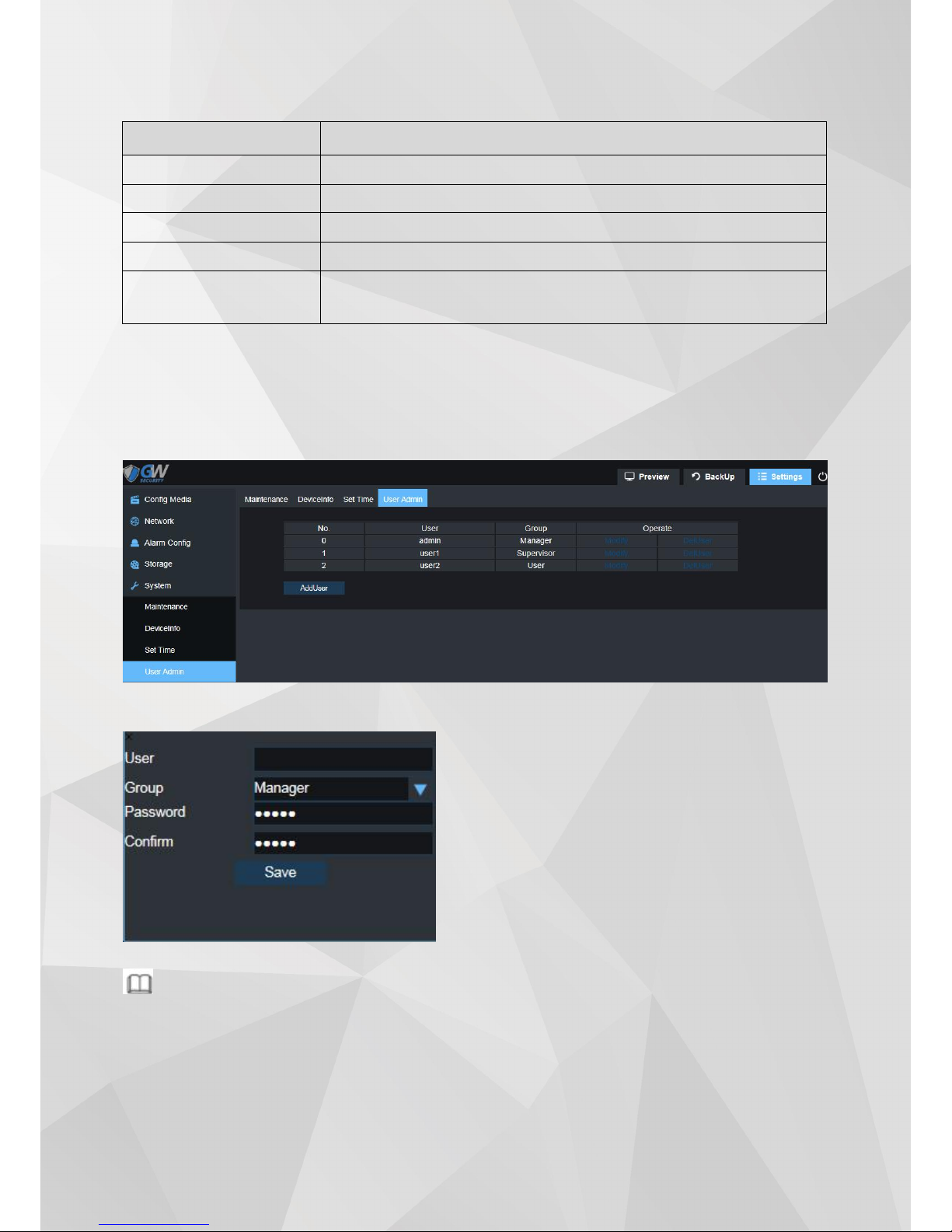
4.6.4 User Admin
Step 1 Select “Settings > System > User Admin” See pic ture bel ow for reference:
Step 2 Click “Add User”to add a user for IPC.
Note
User 1, User2 cannot be deleted, only allow modifying password. New added user is allow to be deleted.
Parameter
Desc rip tion
Time zone
Set IPC time zone
Time
Manu ally set ti me when nec essary
PC Time Sync
Set SYNC tim e with PC
NTP
Set if enabl e SYNC network time function, default is “enable”.
NTP Ser ver
Set NTP server add ress, default is “time.windo ws.com”.
User: Create an user fo r IPC .
Group:Provi de Manager, maintainer, user 3 level
opti on.
Password : Chan ge user pas sword .
Confirm : C on firm passwo rd.
Page 34

37
Glossary of Terms
1 WDR
WDR (Wide Dynamic Range) is the technique aim to reproduce a similar range of luminance through
adapting to the different exposure level presented in the environment, by collecting two different level of
exposure of the same picture twice and combining them. The WDR feature will allow the dark area to be
brighter and darken over-expose area, allowing detail other-wise dampened by over-exposure (glare) and
under-exposure.
2 DWDR
With the same aim as WDR, DWDR (Digital Wide Dynamic Range) adjust the exposure by digitally adjusting
the contrast and gamma value of the picture, reducing the effect of glare. Unlike WDR is done by the hardware,
DWDR may cause the picture to appear washed-out.
3 BLC
BLC (Backlight Compensation) increase the overall exposure of the entire picture to reduce the contrast
between the background and the main interest area. The overall viewable area will improve but area with
brightly-lit area will be overexposed.
4 HLC
HLC (Highlight Compensation) reduce the overall exposure in the main interest area to reduce the effect of
strong light. It is the reverse of BLC because HLC target the lighting generated in the main interest area.
5 3DNR
3DNR (3D Noise Reduction) is the technique used to reduce video noise by analyzing and compare the
difference between each successive frames in order to adjust video pixel. With 3DNR, there will be a trade-off
between video crisp and motion blur.
6 IPv6
IPv6 is the next version of IP (Internet Protocol), the communication protocol that provides an identification
and location system for traffic-routing across the networks. It is designed by IETF (Internet Engineering Task
Force) to replace IPv4 in the anticipation of IPv4 address exhaustion.
7 FTP
FTP (File transfer Protocol) is a protocol used to transfer files between two end-points (computers) on a
network. FTP is an application that exists in different operation system which follows the same set of standard
for file transportation, allowing file transfer across different platforms.
8 DHCP
DHCP (Dynamic Host Configuration Protocol) is a network protocol that allows a server (in most cases, a
router/modem) to automatically assign an IP address to a connected device from a defined range of IP numbers.
DHCP allows a uniformly assigned network environment across different devices.
9 DDNS
DDNS (Dynamic Domain Name System) is a system to automatically update the client ’s dynamic IP address
to a static domain name, thus allow a consistent connection without the need to check dynamic IP address. The
update client will send the IP address in real time, based on a predefined interval, to a server hosting the static
domain name, which in term allows other domain name server to acknowledge the new IP address, without the
need to manually changing the record.
Page 35

38
10 PPPOE
PPPoE (Point-to-Point Protocol over Ethernet) is a network protocol for encapsulating Point-to-Point
Protocol (PPP) frames inside Ethernet frames. It is used mainly with DSL services where individual users connect
to a DSL modem over Ethernet.
11 RTSP
RTSP (Real Time Streaming Protocol) is a network protocol designed to allow system to control streaming
media servers and is used to establish and control media session between two end-points over TCP/IP.
12 ONVIF
ONVIF is the global and open industry standard for interfacing between video surveillance product and
other physical security areas. The standard defines device discoveries, live video and audio standard, bit rate,
and controls, ensuring compatibility between different manufacturer.
13 H265
H.265 is the successor to the H.264 video encoding standard. The aim for H.265 is to improve bit rate, video
quality, and overall video performance. Compare to H.264, H.265 only needs half of the require data to achieve
the same video quality as H.264.
14 HTTP S
HTTPS (Hyper Text Transfer Protocol Secure) is the secure version of HTTP, the protocol which data is sent
between browser and the website connected to. The 'S' at the end of HTTPS stands for 'Secure'. It means all
communications between your browser and the website are encrypted using SSL.
 Loading...