


Programmable Power Supply
PSH series
USER MANUAL
ISO-9001 CERTIFIED MANUFACTURER

This manual contains proprietary information, which is
protected by copyrights. All rights are reserved. No part of this
manual may be photocopied, reproduced or translated to
another language without prior written consent of Good Will
company.
The information in this manual was correct at the time of printing.
However, Good Will continues to improve products and reserves
the rights to change specification, equipment, and maintenance
procedures at any time without notice.
Good Will Instrument Co., Ltd.
No. 7-1, Jhongsing Rd., Tucheng Dist., New Taipei City 236, Taiwan.

Table of Contents
Table of Contents
Safety Instructions ........................................ 5
Safety Symbols .......................................... 6
Safety Guidelines ........................................ 6
Power cord for the United Kingdom ............... 9
PSH Overview ...............................................10
Main Features ........................................... 12
PSH Series Lineup ..................................... 13
Package Contents ..................................... 14
Front Panel .............................................. 16
Rear Panel ............................................... 18
Display .................................................... 19
Setup ............................................................21
AC Power Cable Assembly .......................... 22
Remote Sensing and Local Sensing ............. 24
Load / Remote Sensing Wire Selection ......... 25
Load Configuration .................................... 27
Load Wire Assembly .................................. 31
Remote Sensing Wire Assembly .................. 33
Functionality Check ................................... 35
Rack Mounting (Optional) .......................... 41
Panel Operation ............................................44
Menu Key Overview .................................. 45
Constant Voltage/ Constant Current
Crossover Characteristic ............................ 46
Output Voltage Setting .............................. 47
Output Current Setting .............................. 48
OVP (Output Voltage Protection) Setting ...... 49
OCP (Output Current Protection) Setting ...... 50
Display Contrast Setting ............................ 51
3

PSH User Manual
Buzzer sound Setting ................................ 52
Remote Operation ......................................... 53
Interface Selection .................................... 54
Command Syntax ..................................... 58
Command Set .......................................... 59
Calibration .................................................... 62
Calibration Preparation .............................. 63
Entering calibration mode .......................... 64
Output Voltage calibration .......................... 65
Output Current calibration.......................... 67
OVP Calibration ........................................ 69
FAQ ............................................................... 70
Appendix ....................................................... 72
Specifications ........................................... 72
Index ...................................................... 77
4

Safety Instructions
Safety Symbols
Safety Symbols ......................................... 6
Safety
Guidelines
Safety Guidelines ....................................... 6
Power Supply ............................................ 7
Fuse ......................................................... 7
Cleaning PSH ............................................ 7
Operation Environment ............................... 8
Storage Environment ................................. 8
Power cord
Power cord for the United Kingdom .............. 9
Safety Instructions
This chapter contains important safety
instructions that must be followed when
operating PSH and when keeping it in storage.
Read the following before any operation to
insure safety and to keep the best condition for
PSH.
5
PSH User Manual
WARNING
Warning: Identifies conditions or practices that
could result in injury or loss of life.
CAUTION
Caution: Identifies conditions or practices that
could result in damage to PSH or to other
properties.
DANGER High Voltage
Attention Refer to Manual
Protective Conductor Terminal
Earth (ground) Terminal
General
Guideline
CAUTION
Do not place any heavy object on PSH.
Avoid severe impacts or rough handling that
leads to damaging PSH.
Do not discharge static electricity to PSH.
Do not block or obstruct cooling fan vent
opening.
Do not perform measurements at power
source and building installation site (Note
below).
Do not disassemble PSH unless you are
qualified as service personnel.
(Note) EN 61010-1 specifies the measurement categories
and their requirements as follows. PSH falls under
Safety Symbols
These safety symbols may appear in this manual or on PSH.
Safety Guidelines
6

Safety Instructions
category II.
Measurement category IV is for measurement performed
at the source of low-voltage installation.
Measurement category III is for measurement performed
in the building installation.
Measurement category II is for measurement performed
on the circuits directly connected to the low voltage
installation.
Power Supply
WARNING
Input voltage: 90 ~ 264 V AC,
Frequency: 47~63 Hz
Connect the protective grounding conductor
of the power cord to earth ground, to avoid
electrical shock.
Fuse
WARNING
PSH-2018A
6.3A/250V x2
PSH-3610A
PSH-3620A
6.3A/250V x2
0.5A/250V x1
15A/250V x1
PSH-3630A
6.3A/250V x3
0.5A/250V x1
20A/250V x1
Make sure the correct type of fuse is installed
before powering up.
Replace the fuse with the specified type and
rating only, for continued fire protection.
Disconnect the power cord before fuse
replacement.
Make sure the cause of the fuse blowout is
fixed before fuse replacement.
Cleaning PSH
Disconnect the power cord before cleaning.
Use a soft cloth dampened in a solution of
mild detergent and water. Do not spray any
liquid into PSH.
Do not use chemicals or cleaners containing
harsh materials such as benzene, toluene,
xylene, and acetone.
7

PSH User Manual
Operation
Environment
WARNING
Location: Indoor, no direct sunlight, dust free,
almost non-conductive pollution (Note below)
Relative Humidity: < 85%
Altitude: < 2000m
Temperature: 0°C to 40°C
Input Breaker Capacity: Over 20A (PSH-3630A)
This is a Class A product which may cause
radio interference in a domestic environment.
In such case, take adequate measures.
(Note) EN 61010-1 specifies the pollution degrees and
their requirements as follows. PSH falls under degree 2.
Pollution refers to “addition of foreign matter, solid,
liquid, or gaseous (ionized gases), that may produce a
reduction of dielectric strength or surface resistivity”.
Pollution degree 1: No pollution or only dry,
non-conductive pollution occurs. The pollution has no
influence.
Pollution degree 2: Normally only non-conductive
pollution occurs. Occasionally, however, a temporary
conductivity caused by condensation must be expected.
Pollution degree 3: Conductive pollution occurs, or dry,
non-conductive pollution occurs which becomes
conductive due to condensation which is expected. In
such conditions, equipment is normally protected
against exposure to direct sunlight, precipitation, and
full wind pressure, but neither temperature nor
humidity is controlled.
Storage
Environment
Location: Indoor
Relative Humidity: < 70%
Temperature: −10°C to 70°C
8

Safety Instructions
Green/ Yellow:
Earth
Blue:
Neutral
Brown:
Live (Phase)
Power cord for the United Kingdom
When using PSH in the United Kingdom, make sure the power
cord meets the following safety instructions.
NOTE: This lead / appliance must only be wired by competent persons
WARNING: THIS APPLIANCE MUST BE EARTHED
IMPORTANT: The wires in this lead are coloured in accordance with the
following code:
As the colours of the wires in main leads may not correspond with the colours
marking identified in your plug/appliance, proceed as follows:
The wire which is coloured Green & Yellow must be connected to the Earth
terminal marked with the letter E or by the earth symbol or coloured Green
or Green & Yellow.
The wire which is coloured Blue must be connected to the terminal which is
marked with the letter N or coloured Blue or Black.
The wire which is coloured Brown must be connected to the terminal marked
with the letter L or P or coloured Brown or Red.
If in doubt, consult the instructions provided with the equipment or contact
the supplier.
This cable/appliance should be protected by a suitably rated and approved
HBC mains fuse: refer to the rating information on the equipment and/or user
instructions for details. As a guide, cable of 0.75mm2 should be protected by a
3A or 5A fuse. Larger conductors would normally require 13A types,
depending on the connection method used.
Any moulded mains connector that requires removal /replacement must be
destroyed by removal of any fuse & fuse carrier and disposed of immediately,
as a plug with bared wires is hazardous if a engaged in live socket. Any
re-wiring must be carried out in accordance with the information detailed on
this label.
9

PSH User Manual
Main features
Main Features .......................................... 12
Series lineup
360W ..................................................... 13
720W ..................................................... 13
1080W ................................................... 13
Package
contents
Main unit ................................................ 14
AC input cable kit .................................... 14
Output connection kit ............................... 15
Manual ................................................... 15
Panel
descriptions
Front Panel ............................................. 16
Rear Panel .............................................. 18
Display
Default display ........................................ 19
PSH Overview
PSH Series are modular-type programmable
switching power supplies designed for broad
range of applications. The series consists of 12
models, output ranging from 360W to 1000W.
Switching technology and built-in PFC control
give PSH higher power efficiency, power density,
and power factor compared with other linear
power supplies. Protection mechanisms keep the
output voltage, current, and temperature within
limit. Remote control interface equipped with
SCPI command set and Lab-View Driver
facilitates ATE software development.
This chapter describes PSH series features and
appearances in a nutshell.
10

PSH Overview
descriptions
Menu mode display .................................. 20
11

PSH User Manual
Performance
4 models: 20V/18A, 36V/10A, 36V/20A and
36V/30A
High power factor with PFC control
High efficiency power conversion
Compact size, light weight
Operation
Constant voltage operation
Constant current operation
Output On/Off control
Built-in buzzer
Self test and calibration
LCD display
Protection
Over voltage protection (OVP)
Over current protection (OCP)
Over temperature protection (OTP)
Interface
RS-232 (standard) / GPIB (optional) interface
IEEE 488.2/SCPI compatible command set
LabView driver
Optional items
GPIB remote control interface
19 inch standard rack mounting
Main Features
12
PSH Overview
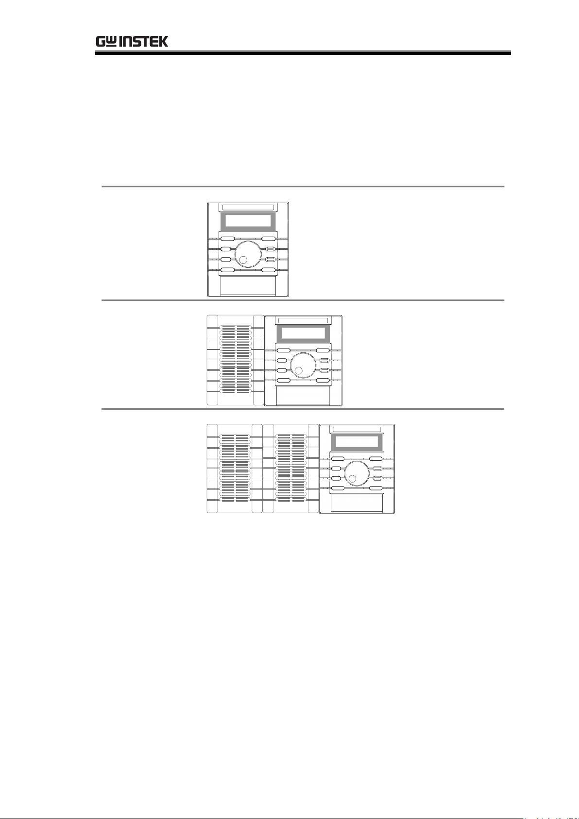
360W
(Mainframe
only)
PSH-2018A
20V, 18A
PSH-3610A
36V, 10A
720W
(Mainframe +
one slave
module)
PSH-3620A
36V, 20A
1080W
(Mainframe +
two slave
modules)
PSH-3630A
36V, 30A
PSH Series Lineup
PSH series consist of the following 12 models with various output
voltage and current ratings. For the detailed specifications, see
page72.
13
PSH User Manual
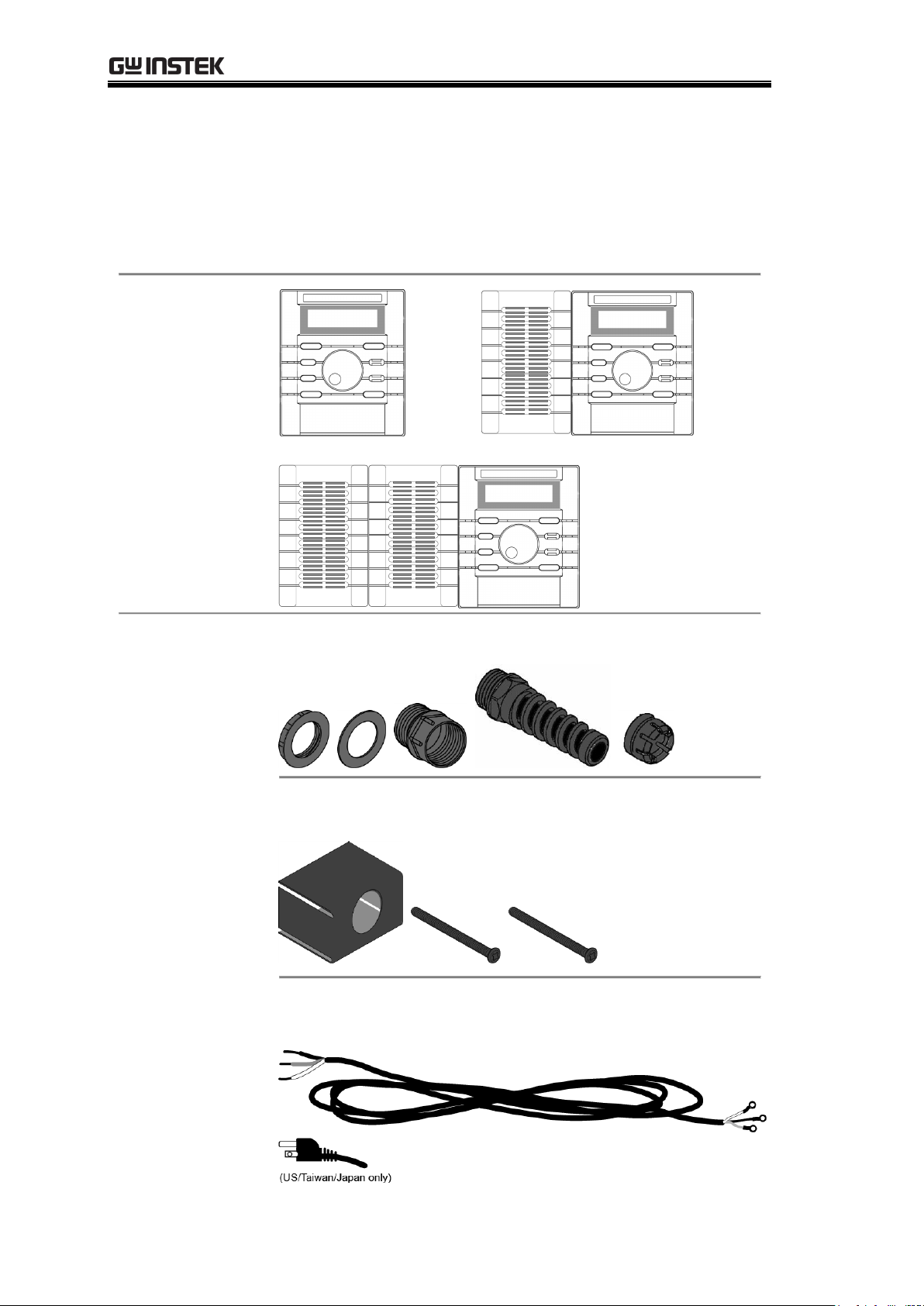
Main unit
AC input cable
kit
Cable gland
Terminal cover
AC power input cord
Package Contents
Check the contents before using PSH series. Contact your local
dealer in case there is a missing item.
14
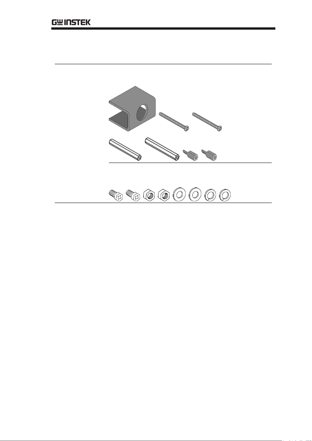
PSH Overview
Output
connection kit
Terminal cover
Output cable screw
Manual
User manual (this document)
Programming manual
Package Contents (cont.)
15

PSH User Manual
1
LCD Display
Shows the output and the configuration status.
See page19 for details.
2
Power
Switch
On Off
3
Wheel knob
Sets parameters. Turn right: increase, turn left:
decrease.
4
Output
Switch
Turns the output On or Off. When On, the
“OUT” sign appears on the display.
Out On
OCP OUT
CV 2.58V 2.01A
Out Off
OCP
SET 2.58 V 2.01 A
Front Panel
16
PSH Overview
5
Vset/ Iset/
Enter key
Switches between voltage setting mode and
current setting mode, or confirm the entered
value in the menu mode (see page45).
Vset (edit Voltage)
OCP
SET 2.58 V 2.01 A
Iset (edit Current)
OCP
SET 2.58 V 2.01 A
6
F/C (Fine/
Coarse) key
Switches the editing location and resolution:
before (coarse) or after (fine) the decimal point.
Fine (after decimal)
OCP
SET 2.58V 2.01A
Coarse (before decimal)
OCP
SET 2.58V 2.01A
7
Menu key
Enters into the menu mode. For details, see
page45.
Default mode
OCP OUT
CV 2.58V 2.01A
Menu mode (OVP setting)
Set OVP
* 21.10V
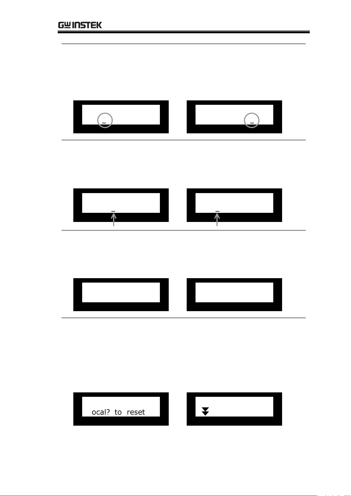
8
Local key
Switches from remote control mode to local
operation mode (page57), OR releases OVP/OCP
error messages and go back to normal operation
(page38), OR enters the calibration mode when
pressed for more than 5 seconds (page62).
Error message example
OCP Error! Press
Calibration mode
Calibration
Voltage
17
PSH User Manual
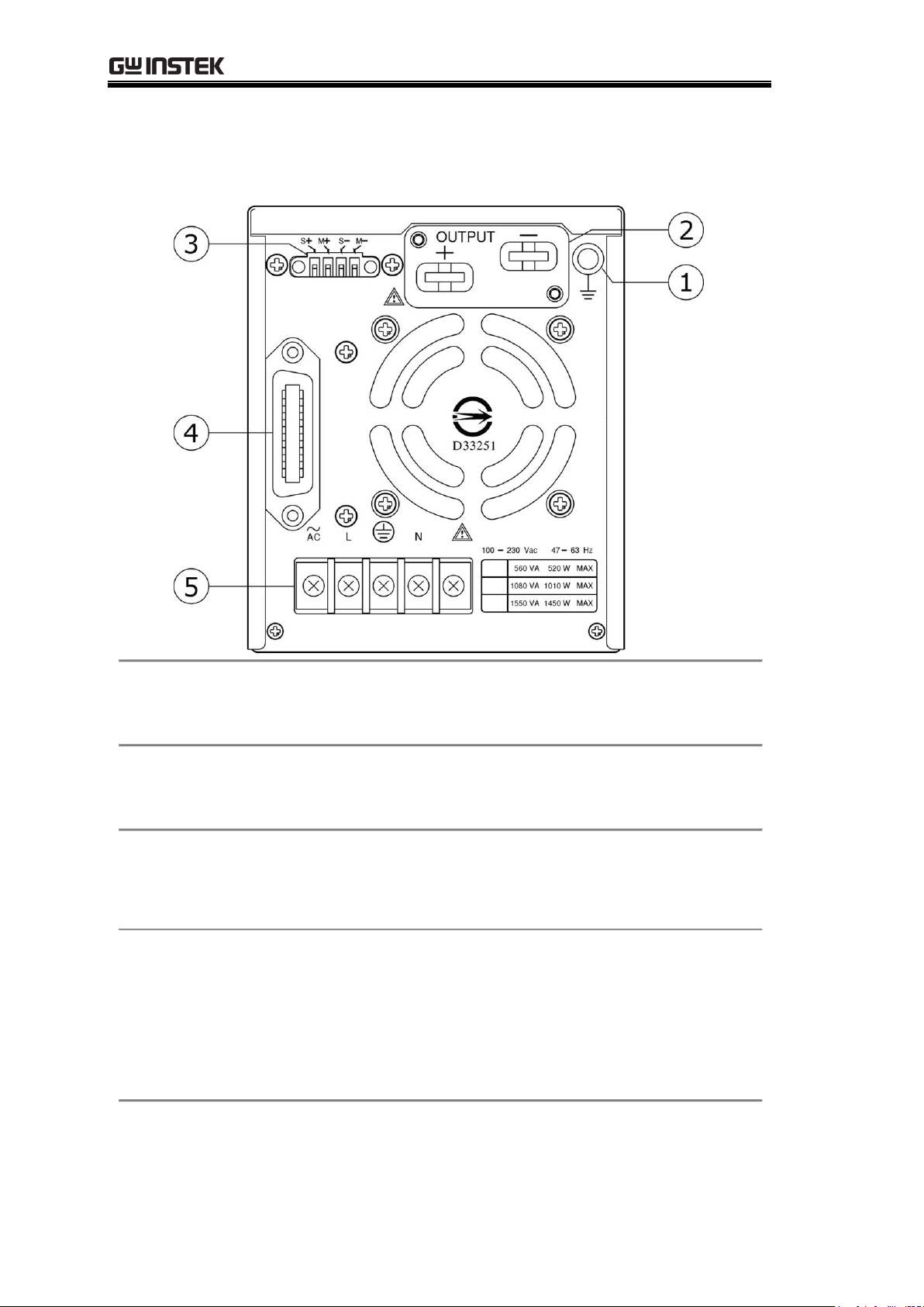
1
Ground
Terminal
Connect the output line shield (page25) and
the remote sensing line shield (page33).
2
Output
Terminal
Connect DUT (Device Under Test). For
details, see page24.
3
Sense Terminal
Connect the feedback line to compensate for
cable loss. For details, see page24 (theory),
page33 (cable connection).
4
RS232/ GPIB
Terminal
Connect the remote control line. For remote
control details, see page53. GPIB requires an
optional module. For installation details, see
the service manual.
Note: Only one interface module (RS232 or
GPIB) can be installed at a time.
5
AC input
Terminal
Connect the AC power input cable. For
details, see page22.
Rear Panel
18

Display
Default
display
Display mode
RMT ADRS OCP OUT
CV 10.10V 36.10A
A B C D
E F G
Editing mode
OCP
SET 10.10V 36.10A
A B C D
E F G
A
RMT: remote control mode
(Nothing): panel operation mode
Not available in editing mode
B
ADRS: RS-232 or GPIB address
(available in remote control)
Not available in editing mode
C
OCP: Output Current Protection On
(Nothing): Output Current Protection Off
D
OUT: Output On
(Nothing): Output Off
Not available in editing mode
E
CV/CC: Current and Voltage display
mode (Constant Voltage/ Constant
Current)
SET: Current and Voltage editing mode
F
Output Voltage readback value (display
mode)
Output Voltage setting value (editing
mode)
G
Output Current readback value (display
mode)
Output Current setting value (editing
mode)
PSH Overview
19
PSH User Manual
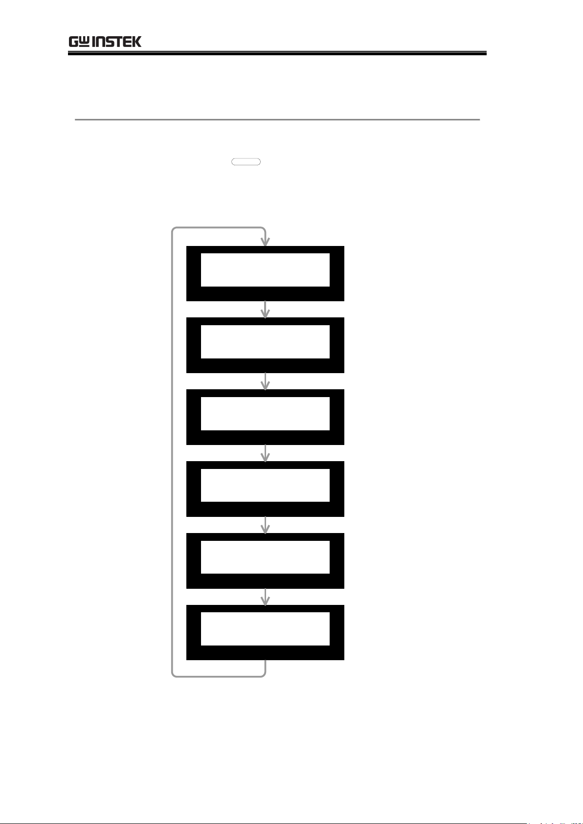
Menu mode
display
The following displays appear when pressing the
Menu key
MENU
. To move to the next
configuration, press the Menu key repeatedly.
When inactive for more than 5 seconds, the
display goes back to the default mode.
Set OVP
21.10V
Set OCP
ON (OFF)
Set Contrast
70%
Set Buzzer
ON (OFF)
Interface RS232
Baud Rate 9600
OCP OUT
CV 2.58V 2.01A
(Default display)
Output Voltage
Protection setting.
For details, see
page49.
Output Current
Protection setting.
For details, see
page50.
Display contrast
setting. For details,
see page51.
Buzzer setting. For
details, see page52.
Remote control
interface setting.
For details, see
page53.
Display (cont.)
20

Setup
AC power cable
assembly
AC Power Cable Assembly ......................... 22
AC power cable requirement ..................... 23
Load
configuration
Remote Sensing and Local Sensing ............ 24
Load / Remote Sensing Wire Selection ........ 25
Single Load + Local Sensing ...................... 27
Single Load + Remote Sensing .................. 27
Multiple Loads + Local Sensing .................. 28
Multiple Loads + Remote Sensing .............. 28
Series Operation + Local Sensing .............. 29
Series Operation + Remote Sensing ........... 30
Wire assembly
Load Wire Assembly ................................. 31
Remote Sensing Wire Assembly ................. 33
Functionality
Check
Preparation ............................................. 35
Output Voltage & OVP Check ..................... 36
Output Current Check .............................. 38
OCP Check .............................................. 39
Rack mounting
(optional)
Rack mounting kit contents ....................... 41
Rack mounting assembly .......................... 42
Setup
This chapter describes load configurations and
setup procedures. Follow these instructions to
properly install PSH series.
21

PSH User Manual
1 Cable gland +
Terminal Cover
Put the power cable through the cable gland
and the terminal cover, screw them together.
2 Cable wire +
Terminal
CAUTION
Screw the wire onto the AC input terminal. Note
the wire color: Neutral (white), GND (green), and
Line (black).
3 Terminal
cover +
Terminal
Screw the terminal cover onto the terminal.
AC Power Cable Assembly
22

Setup
Cable length
≤ 3m
Cable gland
KSS or PG-2013
Cable type
(recommended)
Model: SJT
Type: 3 x 14 AWG stranded copper
Rating: 60°C min, 300V
Diameter: 9.143~10.03 mm
Model: H05 VV-F
Type: 3G 1.5mm2 stranded copper
Rating: 300V/500V
Diameter: 8.5 ± 0.2 mm
AC power cable requirement
Here is the AC power cable specification, in case of using cables
other than the attached one.
23

PSH User Manual
Local Sensing
(default)
VSET = VOUT
VOUT >
VLOAD
VOUT VLOAD
VOUT
Output
Setting
VSET
|VSET–VOUT|
Sense
PSH Load
The sense terminal is internally connected to the
PSH output terminal. The delta between the
voltage setting level (VSET) and the actual output
level (VOUT) is compensated. The load terminal
voltage (VLOAD) might become lower than the
output due to cable loss.
Remote
Sensing
VSET =
VLOAD
VOUT > VSET
PSH Load
Sense
VOUT VLOAD
VLOAD
Output
Setting
VSET
|VSET–VLOAD|
The sense terminal is connected to the load input
terminal. The delta between the voltage setting
level (VSET) and the actual load voltage (VLOAD) is
compensated. The output voltage (VOUT) might
become higher than the setting due to the
compensation.
Remote Sensing and Local Sensing
Remote sensing compensates the cable loss between PSH and load,
up to 0.5V. Use remote sensing whenever the load voltage has to
be accurate.
24
 Loading...